Multi-Domain Electric Drivetrain Modeling for UAM-Scale ...
14
Multi-Domain Electric Drivetrain Modeling for UAM-Scale eVTOL Aircraft Meaghan Podlaski Graduate Student Robert Niemiec Research Scientist Luigi Vanfretti Associate Professor Farhan Gandhi MOVE Director ABSTRACT This paper presents the modeling and validation of an electric drivetrain through an object-oriented, equation-based framework that includes aerodynamics, electric machine, power electronic converter and battery models at various levels of detail. The proposed drivetrain model considers different losses in the machine and levels of fidelity for the power source and converters. It is simulated with various maneuvers, aiming to show the effects of modeling simplifications on the behavior of UAMs. These studies show that the level of detail in the motors and power system has significant impact on the dynamic response and power consumption of the system. This is most evident in the cases where the system uses a detailed battery model and in the cases where the switching electrical components are used, creating a torque ripple. NOTATION b Motor friction constant EMF Electromotive force i Motor current I Motor effective inertia i np Battery cell current for the nth cell in series and pth cell in parallel K e Motor transformation coefficient L Motor inductance OCV Open circuit voltage OCV np Battery open circuit voltage for the nth cell in series and pth cell in parallel R Motor resistance P loss,d Frictional loss in the motor PW M Pulse width modulation Q aero Moment of the aerodynamic torque Q motor Moment of the motor SoC State of charge V a Voltage applied to the motor V battery Battery cell voltage for the nth cell in series and pth cell in parallel X Motor impedance Z battery Battery impedance for the nth cell in series and pth cell in parallel Ω Motor speed Ω out Motor speed Ω re f Reference motor speed τ Torque generated by the motor τ a Time constant for the motor impedance τ d Torque applied to the damper in the motor τ out Torque applied to the rotor model from the motor τ rotor Torque produced by the rotor model Presented at at the VFS International 77th Annual Forum & Technology Display, May 10–14, 2021. Copyright © 2021 by the Vertical Flight Society. All rights reserved. INTRODUCTION Distributed electric propulsion has enabled a vast array of new concept vehicles, largely centered around NASA’s Ad- vanced Air Mobility (AAM) initiative (Ref. 1) and Uber El- evate (Ref. 2). Most of these concepts take advantage of the ability of electric motors to operate at a relatively wide range of RPM compared to conventional turbine-driven drivetrains, which have a narrow band of efficient operating speeds. Within the VTOL community, substantial attention has been paid to the effectiveness of variable-RPM rotor systems on Urban Air Mobility, a subset of AAM, focused on passen- ger transport operations. Variable-RPM rotor systems were compared to variable-pitch systems at NASA Ames Research Center (Refs. 3, 4), and at the Center for Mobility with Vertical Lift (MOVE, Ref. 5). Both of these studies examined variants of the quadcopter concept put forward in (Ref. 6), finding that variable-RPM systems were not viable unless drivetrain limits were significantly higher than current design trends suggest. In Ref. 5, it was found that these same limitations were appli- cable to variable-pitch systems, due to the large motor torque required to meet yaw handling qualities specifications. Also at MOVE, recent work (Ref. 7) explored the impact of motor dynamics on the handling qualities of single-passenger vehicles with different numbers of rotors at a fixed gross weight and disk loading, and related research (Ref. 8) ex- plored the same on quadcopters at different AAM-relevant scales. Both studies generally found that having smaller ro- tors, whether by possessing more, smaller rotors or operating at a lower gross weight, reduced the over-sizing necessary for the motors to handle current commands during maneuvers. All of the above studies utilized an idealized motor model, using simplified DC motor equations to capture motor dy- namics, treating the armature voltage as a command. How- ever, electrical machine dynamics are much more complex than the behavior described by such equations (Refs. 9, 10). In addition, the ideal DC motor model neglects the effects of the electronic speed controller (Ref. 11), which provides the 1
Transcript of Multi-Domain Electric Drivetrain Modeling for UAM-Scale ...

Multi-Domain Electric Drivetrain Modeling for UAM-Scale eVTOL Aircraft
Meaghan PodlaskiGraduate Student
Robert NiemiecResearch Scientist
Luigi VanfrettiAssociate Professor
Farhan GandhiMOVE Director
ABSTRACTThis paper presents the modeling and validation of an electric drivetrain through an object-oriented, equation-basedframework that includes aerodynamics, electric machine, power electronic converter and battery models at variouslevels of detail. The proposed drivetrain model considers different losses in the machine and levels of fidelity forthe power source and converters. It is simulated with various maneuvers, aiming to show the effects of modelingsimplifications on the behavior of UAMs. These studies show that the level of detail in the motors and power systemhas significant impact on the dynamic response and power consumption of the system. This is most evident in thecases where the system uses a detailed battery model and in the cases where the switching electrical components areused, creating a torque ripple.
NOTATION
b Motor friction constantEMF Electromotive forcei Motor currentI Motor effective inertiainp Battery cell current for the nth cell in series and
pth cell in parallelKe Motor transformation coefficientL Motor inductanceOCV Open circuit voltageOCVnp Battery open circuit voltage for the nth cell in
series and pth cell in parallelR Motor resistancePloss,d Frictional loss in the motorPWM Pulse width modulationQaero Moment of the aerodynamic torqueQmotor Moment of the motorSoC State of chargeVa Voltage applied to the motorVbattery Battery cell voltage for the nth cell in series and
pth cell in parallelX Motor impedanceZbattery Battery impedance for the nth cell in series and
pth cell in parallelΩ Motor speedΩout Motor speedΩre f Reference motor speedτ Torque generated by the motorτa Time constant for the motor impedanceτd Torque applied to the damper in the motorτout Torque applied to the rotor model from the motorτrotor Torque produced by the rotor model
Presented at at the VFS International 77th Annual Forum &Technology Display, May 10–14, 2021. Copyright © 2021 by theVertical Flight Society. All rights reserved.
INTRODUCTION
Distributed electric propulsion has enabled a vast array ofnew concept vehicles, largely centered around NASA’s Ad-vanced Air Mobility (AAM) initiative (Ref. 1) and Uber El-evate (Ref. 2). Most of these concepts take advantage of theability of electric motors to operate at a relatively wide rangeof RPM compared to conventional turbine-driven drivetrains,which have a narrow band of efficient operating speeds.
Within the VTOL community, substantial attention has beenpaid to the effectiveness of variable-RPM rotor systems onUrban Air Mobility, a subset of AAM, focused on passen-ger transport operations. Variable-RPM rotor systems werecompared to variable-pitch systems at NASA Ames ResearchCenter (Refs. 3,4), and at the Center for Mobility with VerticalLift (MOVE, Ref. 5). Both of these studies examined variantsof the quadcopter concept put forward in (Ref. 6), finding thatvariable-RPM systems were not viable unless drivetrain limitswere significantly higher than current design trends suggest.In Ref. 5, it was found that these same limitations were appli-cable to variable-pitch systems, due to the large motor torquerequired to meet yaw handling qualities specifications.
Also at MOVE, recent work (Ref. 7) explored the impact ofmotor dynamics on the handling qualities of single-passengervehicles with different numbers of rotors at a fixed grossweight and disk loading, and related research (Ref. 8) ex-plored the same on quadcopters at different AAM-relevantscales. Both studies generally found that having smaller ro-tors, whether by possessing more, smaller rotors or operatingat a lower gross weight, reduced the over-sizing necessary forthe motors to handle current commands during maneuvers.
All of the above studies utilized an idealized motor model,using simplified DC motor equations to capture motor dy-namics, treating the armature voltage as a command. How-ever, electrical machine dynamics are much more complexthan the behavior described by such equations (Refs. 9, 10).In addition, the ideal DC motor model neglects the effects ofthe electronic speed controller (Ref. 11), which provides the
1

commands to change the voltage and/or current to differentparts of the stator (the stationary component of a brushlessDC motor), called “phases.” The rapid switching of voltageand/or current required to track a desired speed is carried outby a DC/DC power electronic converter (Ref. 10). Such con-verters have different internal switch configurations (knownas topologies, (Ref. 12) and control modes (Refs. 11, 13), e.g.armature voltage control or field-oriented control, (Ref. 14),which result in switching losses at the converter itself. More-over, the switching also introduces a distortion known as volt-age/current ripple to the motor terminals. While filters formedby passive components (capacitors and inductors) can be de-signed to minimize the ripple, it is impossible to completelyremove it (Refs. 14,15). Regardless of its magnitude, the volt-age/current ripple will affect the desired performance of themotor and lead to different types of losses in the machine,most of which will ultimately impact the thermal manage-ment needs (Ref. 16) and result in torque ripple that may leadto unacceptable speed ripple, vibration, and acoustic noise(Ref. 17), all of which reduce the handling qualities and life-time of the drivetrain. All of these aspects are impossible tocapture using the simplified DC motor equations.
Previous studies have also assumed that the battery is a con-stant voltage source, without regard to aging, or power drainover the course of a flight. Naturally, as batteries dischargeover the course of a flight, the pack voltage will drop, increas-ing the strain on the system (as voltage drops, current has tobe increased to deliver the same amount of power), demand-ing additional effort from the DC/DC converter to deliver therequired voltage/current and possibly leading to inadequatehandling qualities or even a loss of control.
More sophisticated motor and battery models have been im-plemented on eVTOLs (Refs. 18–20), though these studiesprimarily examine performance metrics such as efficiency.However, higher-fidelity drivetrain models are needed forother design aspects such as thermal management (Refs. 16,21), response and mitigation to failures (Refs. 21, 22), im-pact on aircraft handling (Refs. 17, 23), etc. For example, theimportance of high-fidelity drivetrain modeling can be under-stood from results in Ref. 24, where a switched inverter modelis connected to a battery and motor in a quadcopter. Largevoltage and current ripples were created by transistor switch-ing in the converter, which impacted system operation de-pending on the converter topology (Ref. 12), control (Ref. 13),etc. Higher-fidelity models would therefore allow for morerealistic analyses, providing a broader insight to the experi-ments such as those in (Refs. 18–20), and to integrate elec-trical powertrains with other subsystems that depend on theirperformance, i.e. aerodynamic and thermal.
The objectives of the present study are:
• Application of multi-engineering domain (mechanical-electrical) models for an electric drivetrain with varyingdegrees of complexity, including detailed battery, ma-chine, and power electronic converter models.
• Modeling drivetrain response for power source models,
including an ideal power source, fully charged battery,and battery at 30% charge.
• Comparing drivetrain response for different machineconfigurations under various speed commands, namelyquadcopters with fully-distributed batteries (where eachmotor has a dedicated power source) and a fully-centralized battery (where all rotors share a single powersource).
Paper Organization
First, the drivetrain model is introduced and outlined. Allof the components and variants of those components are ex-plained.
In the next section, a second order speed command is appliedto the drivetrain models to study their aerodynamic responseand electrical dynamics.
Next, the brushless averaged DC motor is put into a quadrotorconfiguration. A heave, pitch, and roll maneuver is applied tothe system using an ideal power source, fully charged battery,and battery at 30% charge. This allows us to study the impactof the battery’s state of charge on the system performance.
Finally, a comparison of two battery layouts is presented.Specifically, a fully-distributed battery system versus a fully-centralized battery on a 300 lb quadcopter (that used inRef. 8).
MODELING
Platform Description
The vehicle considered in this study is a 300lb quadcopterused in Ref. 8. The properties of this quadcopter and its rotorsare listed in Table 1. The rotors are assumed to be linearlytwisted and tapered and have a 10% R tip clearance. The mo-tor parameters are based on the Hacker Q150-45-4 (Ref. 25),and are also included in Table 1.
The drivetrain consists of four main components: a controller,pulse width modulation (PWM) of the converter, a DC/DCconverter, and a brushless DC machine as shown in Figure 1.Starting from the left-hand side of Fig. 1, a pulse-width modu-lated signal, which defines the instantaneous desired speed ofthe motor (based on vehicle-level control needs) is providedto a speed controller, which, among other things, regulatesthe voltage/current to track the desired speed. The controllerfeeds a signal to a power converter, which steps-up the voltagand commutates the battery voltage to a suitable waveform forthe motor to meet the desired speed. The motor itself convertsthe electrical current to a mechanical torque, which drives therotor at Ωout .
Each component of the drivetrain is modeled at multiple lev-els of fidelity using Dassault Systemes’ Dymola software,which utilizes the equation-based modeling language, Mod-elica (Ref. 26), and contains several libraries for drivetrainmodeling, including the Brushless DC Drive library (Ref. 27),and the Battery library (Ref. 28).
2

Figure 1: Electric powertrain schematic
Table 1: Aircraft ParametersVehicle Parameters
Boom Length (m) 0.905Gross Weight (kg) 136
Ixx (kg m2) 43Iyy (kg m2) 51Izz (kg m2) 84
Rotor ParametersRotor Radius (m) 0.6096
Rotor Inertia (kg m2) 0.063Root Pitch (deg) 21.5
Linear Twist (deg) -10.4Solidity 0.09
Taper Ratio 2.5Motor Parameters
Ke(Nm/A) 0.1342R (Ohm) 0.0155L (µH) 4
b (Nms/rad) 3.71e-4
Motor models
In Figure 1, the motor can be modeled at multiple levels offidelity to include different levels of losses. Four differentmodels are used:
1. Simple DC motor without inductance
2. Simple DC motor with inductance
3. Brushless motor with averaged back EMF
4. Brushless motor with trapezoidal back EMF
Simple DC motor without inductance: The simplest repre-sentation of the motor is shown in Figure 2. The motor speedis governed by Eq. 1, where I represents the effective inertia
Figure 2: Circuit diagram of DC motor without induc-tance.
Figure 3: Circuit diagram of DC motor with inductance.
(including the rotor blades), and the right-hand side is the netmoment. The motor torque is proportional to the current, andthe current is quasi-steady, given by Eq. 3.
IdΩ
dt= Qmotor−Qaero (1)
Qmotor = Kei (2)
i =V −KeΩ
R(3)
Simple DC motor with inductance: An inductance is addedto the motor model in Figure 3. Due to the presence of themachine’s inductance, the current no longer evolves instan-taneously, but is governed by the dynamic equation, Eq. 4.
3

Otherwise, this model is identical to the previous.
Ldidt
=V −Ri−KeΩ (4)
By adding an inductance to the motor, a new time constant(τa) is added to the system. This time constant derivation isshown in Equation 5, where L is the motor inductance and R isthe motor resistance. In many machines, the inductance is sosmall that the time constant does not have much impact on thesystem from the mechanical point of view, but whose electri-cal dynamics cannot be neglected when studying the electri-cal power train itself. For the Hacker Q150-45 brushless ma-chine used in this study, the motor has a resistance of 0.0155Ohm (Ref. 25) and inductance of 4µH (based on regressionin Ref. 4). This results in a time constant of 258.06µs, or asettling time of 1ms. These time contants will interact withthe power electronic converter and it’s controls.
τa =LR
(5)
Brushless DC motor with averaged EMF: The brushlessDC motor with averaged EMF considers builds off the simplemotor models to include frictional losses in the machine. Themotor model is shown in Figure 4. Equation 1 is modified toinclude a viscous torque, resulting in Eq. 6, where b is the ef-fective damping due to viscosity in the air gap between the sta-tor and rotor. Motor torque and current are governed by Eqs. 2and 4, respectively. For the Hacker Q150-45, b = 3.71e−4.
IdΩ
dt= Qmotor−Qaero−bΩ (6)
Figure 4: Circuit diagram of the averaged brushless mo-tor.
Brushless DC motor with trapezoidal EMF: The brush-less DC motor further increases complexity, as the motor’sback EMF is component is replaced with a three-phase trape-zoidal back EMF. Previously, the back EMF is a function ofspeed only; in this model, the back-EMF in each phase is alsodependent on the motor position, as shown in Figure 5. Thewaveform is trapezoidal, therefore, this motor will be referredto as the “Trapezoidal DC motor” throughout this study. Theresistance and inductance in each phase is half that of thewhole motor. In a three phase motor, two phases are always
Figure 5: Back EMF of trapezoidal brushless machinewith a duty cycle of 0.33.
conducting in series, so the impedance of each phase is addedtogether as they are electrically in series with each other.
Since the trapezoidal motor configuration operates in three-phases, the converter and controller models include switchinginstead of the averaged conversion used in the previous mod-els. The converter used with the trapezoidal motor shown inFigure 6 is a by a 3-phase full-bridge inverter that of diodesand transistors (represented as switches), that supplies the mo-tor it they can produce the time-varying back EMF. Finally,the battery voltage needs to be stepped up before convertedby the full-bridge inverter, this is done using an ideal buck-boost converter. Note that this converter is not shown in Fig.6, but is a very commonly used converter (Ref. 14).
The PWM signal applied to the motor’s converter is controlledusing a six-step controller. Each pulse is separated by 60 de-grees electrically to produce three sinusoidal voltages to ap-ply to the machine. In Figure 6, the PWM signals are labelledsuch that there is a signal to control each diode in the converterfor each phase, resulting in six signals.
Battery models
eVTOL systems are commonly modeled with ideal batterysources. Ideal battery sources can deliver any amount of cur-rent while maintaining a constant voltage. However, real-world batteries lose voltage when higher current is drawn(resistive losses and changes in battery chemistry), and ascharge is depleted. These effects can be modeled using atable-based open circuit voltage (OCV) battery. The OCV batteryschematic is shown in Figure 7, where each cell of the bat-tery is modeled as an ideal voltage source, plus resistors andcapacitors. The values of the capacitances and resistancesare functions of the current draw, temperature, and state ofcharge of the battery, and are based on lookup-tables derivedfrom experimental data on the Sanyo 18650 Li-Ion cylindricalcell (Ref. 28). To scale the battery voltage, n cells are wired
4
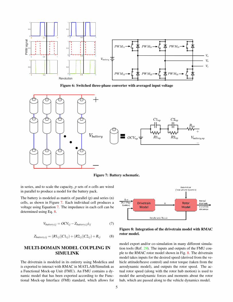
Figure 6: Switched three-phase converter with averaged input voltage
Figure 7: Battery schematic.
in series, and to scale the capacity, p sets of n cells are wiredin parallel to produce a model for the battery pack.
The battery is modeled as matrix of parallel (p) and series (n)cells, as shown in Figure 7. Each individual cell produces avoltage using Equation 7. The impedance in each cell can bedetermined using Eq. 8.
Vbattery,i j = OCVi j−Zbattery,i jii j (7)
Zbattery,i j = (R1i j||C1i j)+(R2i j||C2i j)+Ri j (8)
MULTI-DOMAIN MODEL COUPLING INSIMULINK
The drivetrain is modeled in its entirety using Modelica andis exported to interact with RMAC in MATLAB/Simulink asa Functional Mock-up Unit (FMU). An FMU contains a dy-namic model that has been exported according to the Func-tional Mock-up Interface (FMI) standard, which allows for
Figure 8: Integration of the drivetrain model with RMACrotor model.
model export and/or co-simulation in many different simula-tion tools (Ref. 29). The inputs and outputs of the FMU cou-ple to the RMAC rotor model shown in Fig. 8. The drivetrainmodel takes inputs for the desired speed (derived from the ve-hicle attitude/heave control) and rotor torque (taken from theaerodynamic model), and outputs the rotor speed. The ac-tual rotor speed (along with the rotor hub motion) is used tomodel the aerodynamic forces and moments about the rotorhub, which are passed along to the vehicle dynamics model.
5

Figure 9: Forward Path of Explicit-Model-Following con-troller
Speed Control Architecture
The controller in Fig. 1 is divided into two parts, namelya low-frequency feedback controller (for the regulation ofspeed), and switching controller (to coordinate the switchingin the converter). Naturally, the second component is onlynecessary when switching is actually modeled (only for thetrapezoidal motor in this study), but the first component isneeded for all machine types. The control architecture chosenfor the speed control is explicit-model-following, the forwardpath of which is shown in Fig. 9. First, the reference signal ispassed through a command model, which can be tuned basedon handling qualities requirements (Refs. 5, 7, 8). The com-mand model outputs a commanded speed, Ωcmd, and an accel-eration Ωcmd. In the forward path, the commanded speed andacceleration are passed through a simplified inverse model,which predicts the required voltage input for the motor. Theinverse model is taken from the simple DC motor (neglect-ing aerodynamic torque), without inductance, and used for allmachine types.
G =V0Ke
RIs+K2e
u =1
KeV0
(RIΩcmd +K2
e Ωcmd) (9)
To account for deviations from this simplified model (due toinductance, aerodynamic torque, switching, etc.), feedbackcontrol is also included. For this application, a PI controlleris used, with gains tuned using the simplest DC motor model.To ensure adequate frequency separation from the pitch/rolldynamics of the vehicle (tuned for a crossover frequency of 5rad/s, Ref. 8), a crossover frequency of 25 rad/s for the rotorspeed control loop is chosen. The zero location (the ratio ofthe integral grain to the proportional gain) is selected to be 1/5of the crossover frequency (Ref. 30).
RESULTS
Isolated Rotor
A step command from 150 rad/s to 170 rad/s is commandedto each rotor model. Figures 10a and 10b show the responsefor each of the four machine types. Each of the motors havenearly identical speed responses, which is expected due tothe small inductance and time constant of the motor. De-lays associated with the motor inductance are negligible, ashigh-frequency commands (where the inductance will causemore phase delay) are filtered out by the command model.There is a small difference visible in the initial response ofthe trapezoidal motor, with brief lulls in the acceleration dueto current/torque ripple as the commutating switches open andclose.
(a) First 500ms of the response
(b) First 50ms of the responseFigure 10: Second order speed command response.
While the dynamics of each of the machine configurations arenearly identical, the current draw varies significantly betweenthe motor models, as shown in Fig. 11a. Of the three non-switching motors, it is clear that the simple DC motor requiresthe least current, topping out around 72A. The simple DC mo-tor with inductance and the averaged BLDC motor requiregreater current during the step command, as the inductors be-come charged, drawing a peak of 78A, but is characteristicallysimilar to the model that neglects inductance. The trapezoidalmotor, on the other hand, is characterized by frequent dropsto zero current, as the switching between phases occurs. For abrief moment, both of the switches in Fig. 6 are open, result-ing in zero current.
The level of detail in the machine and converter model alsoimpacts the motor torque. Figure 12a shows that the trape-zoidal brushless motor model has the same switching behaviorseen in the current, again caused by the transistor switching inthe converter. Even without the switching, the inductance cre-ates a small ripple torque, as seen in Figure 12b, though thisis very small in magnitude compared to the switching torqueripple. This type of ripple will cause large periodic loading inthe rotor shaft, which may cause fatigue.
6

(a) First 500ms of the response (b) First 50ms of the responseFigure 11: Motor current when a second order speed command is applied.
(a) First 500ms of the response (b) First 50ms of the responseFigure 12: Motor torque when a second order speed command is applied.
Figure 13: Multi-rotor aircraft model with centralized battery.
7

MULTI-ROTOR SYSTEM
Centralized Battery Architecture
To observe the loads of drivetrain architectures during ma-neuvering flight, the heave and pitch maneuvers are executed.Namely, a 5 m/s climb is commanded for 10 seconds (for a50m climb) followed by a return to hover, and a 10 degreedoublet is executed in pitch. First, a fully centralized bat-tery architecture (Fig. 13), which provides power for all fourmotors, and one with a fully distributed battery (so that eachmotor has an independent power source). Because all of themotors had nearly identical behavior in terms of speed, theaveraged BLDC motor is used in all of the simulations. Threepower sources are used in this study. To match the conditionsin Ref. 8, the second-order filter previously used is replacedwith a first-order filter, tuned to meet ADS-33 handling qual-ities standards.
1. An ideal, 60V voltage source
2. A centralized battery at full charge (beginning of a mis-sion)
3. A centralized battery at 30% charge (end of a mission)
Heave Command To examine the closed-loop behavior inheave, a 5 m/s climb rate is commanded to the vehicle andheld for 10 seconds, so that the vehicle climbs 50m in total.The unfiltered command, along with the vehicle response isgiven by Fig. 14. The difference between the command andresponse is primarily due to the heave command model, whichis first-order (τ = 4.6 sec) by design. Figure 15 shows thecorresponding rotor speed (all four motors receive identicalcommands in heave), and the tracking is nearly perfect for allconfigurations, though there is a very slight lag for both OCVbatteries. Figure 16 shows the current drawn from the batter-ies during the heave maneuver, while Fig. 17 shows the bat-tery voltage during the same. As the initial climb commandis issued, the initial need to increase thrust (and thus rotorspeed) produces an immediate spike in the current draw. As
Figure 14: Heave command and vehicle response.
Figure 15: Speed response of multi-rotor system to heavecommand.
Figure 16: Current response of multi-rotor system toheave command.
Figure 17: Voltage response of multi-rotor system to heavecommand.
8

the vehicle’s climb rate increases, the additional downwash onthe rotors increases the torque, leading to a smooth rise in thecurrent drawn. When the climb command is terminated, therotors slow down, producing a large negative spike in current,and as the aircraft returns to hover, the current and voltageapproach their steady-state values. Generally speaking, theideal voltage source drawn less current than the OCV batter-ies. This is due to the lower voltage delivered by the OCVbatteries (represented by the resistors in Fig. 7) as current isdrawn. The drop in voltage observed for the OCV batteriesduring the climb are also due to increased current demands;when the climb command is stopped, the voltage mostly re-covers to its initial value. Naturally, the 30% charged batteryhas a lower overall voltage than the fully-charged one, so itscurrent demands are even higher (the same power must be de-livered to the motors in all three cases).
Pitch Command To examine the behavior in pitch, a 10 de-gree pitch doublet is commanded to the quadcopter, as shownin Fig. 18. The command model for pitch is a second-ordertransfer function (ζ = 0.7, ωn = 3.46 rad/s). As discussed in(Ref. 8), the vehicle does not track the filtered command well,and the vehicle does not settle to 10 degrees before the dou-blet ends. The rotor speeds during the pitch doublet are shownin Figure 19. The front and rear rotors receive opposite com-mands, since they are on opposite sides of the pitch axis (Fig.20). The current draw from the battery is shown in Figure 21.Unlike the heave command, the large spikes as the maneuverbegins are not observed in the battery current, despite the largespike in the front rotors’ current draw. This is because whilethe front rotors initially speed up (drawing more current), therear rotors slow down (drawing less). Thus, the spikes in thebattery current draw are small, and the corresponding changesin the voltage (Fig. 22) are similarly small. This behavior alsoapplies to the roll and yaw axes. Therefore, when a centralizedbattery architecture is used, heave maneuvers at low chargerepresent the limiting case for battery current delivery.
Figure 18: Pitch command and vehicle response.
Figure 19: Speed response of multi-rotor system to pitchcommand.
Figure 20: Current response of front and rear motors ofmulti-rotor system to pitch command.
9

Figure 21: Current response of multi-rotor systembattery to pitch command.
Figure 22: Voltage of multi-rotor system when pitchcommand is applied.
Figure 23: Multi-rotor aircraft model with individual batteries connected to each motor, creating a distributed archi-tecture.
Figure 24: Speed response of multi-rotor system withindividual batteries to heave command.
Figure 25: Current response of multi-rotor systemwith individual batteries to heave command.
10

Distributed Battery Architecture.
The distributed battery architecture is shown in Figure 23,where each of the motors in the drivetrain has its own powersource. Each of the four batteries is one-fourth the size ofthe single battery pack that drives the centralized architecture.The same heave and pitch maneuvers used on the centralizedbattery architecture are applied to examine the demands onthe powertrain.
Heave Command The heave command in Figure 14 is ap-plied to the multi-rotor system with a distributed battery ar-chitecture. The speed response (shown in Fig. 24) is identicalto that of the centralized battery, as might be expected, con-sidering that heave commands load all four rotors identically.The current draw (Fig. 25) is exactly one-fourth (or shouldbe, once we fix the figure of the current observed for the cen-tralized battery architecture (compare to Fig. 16), an intuitiveresult, since each battery is responsible for one fourth of thepowertrain. Since the capacity of each individual battery isalso one-fourth that of the centralized battery, the voltage be-havior (Fig. 26) is identical to the centralized battery.
Figure 26: Voltage response of multi-rotor system with in-dividual batteries to heave command.
Pitch Command The pitch command and vehicle responseare shown in Figure 18. The rotor speeds during the pitch dou-blet are shown in Figure 27. The ability to track commandedvelocities is identical to the centralized battery architecture(compare to Fig. 19). However, the current response (Fig. 28)is characteristically different. Because the front rotors’ batter-ies are not connected to the rear rotors, the additional currentdrawn during a nose-up is not offset by the reduced current re-quirement of the rear rotors, and vice-versa. Thus, the currentdemands during pitch maneuvers will affect the battery sizingand cooling requirements. The batteries’ voltage also changesduring the doublet (Fig. 29), though not as dramatically asduring the heave maneuver.
Figure 27: Speed response of multi-rotor system with in-dividual batteries to pitch command.
Figure 28: Current response of multi-rotor system withindividual batteries to pitch command.
11
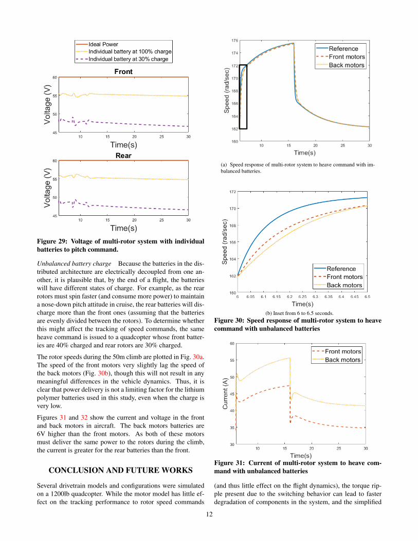
Figure 29: Voltage of multi-rotor system with individualbatteries to pitch command.
Unbalanced battery charge Because the batteries in the dis-tributed architecture are electrically decoupled from one an-other, it is plausible that, by the end of a flight, the batterieswill have different states of charge. For example, as the rearrotors must spin faster (and consume more power) to maintaina nose-down pitch attitude in cruise, the rear batteries will dis-charge more than the front ones (assuming that the batteriesare evenly divided between the rotors). To determine whetherthis might affect the tracking of speed commands, the sameheave command is issued to a quadcopter whose front batter-ies are 40% charged and rear rotors are 30% charged.
The rotor speeds during the 50m climb are plotted in Fig. 30a.The speed of the front motors very slightly lag the speed ofthe back motors (Fig. 30b), though this will not result in anymeaningful differences in the vehicle dynamics. Thus, it isclear that power delivery is not a limiting factor for the lithiumpolymer batteries used in this study, even when the charge isvery low.
Figures 31 and 32 show the current and voltage in the frontand back motors in aircraft. The back motors batteries are6V higher than the front motors. As both of these motorsmust deliver the same power to the rotors during the climb,the current is greater for the rear batteries than the front.
CONCLUSION AND FUTURE WORKS
Several drivetrain models and configurations were simulatedon a 1200lb quadcopter. While the motor model has little ef-fect on the tracking performance to rotor speed commands
(a) Speed response of multi-rotor system to heave command with im-balanced batteries.
(b) Inset from 6 to 6.5 seconds.Figure 30: Speed response of multi-rotor system to heavecommand with unbalanced batteries
Figure 31: Current of multi-rotor system to heave com-mand with unbalanced batteries
(and thus little effect on the flight dynamics), the torque rip-ple present due to the switching behavior can lead to fasterdegradation of components in the system, and the simplified
12

Figure 32: Voltage response of multi-rotor system to heavecommand with unbalanced batteries
models commonly used for flight dynamics are not adequateto capture this phenomenon.
The power source model has noticeable impact on the drive-train performance. Relative to a constant voltage source, theOCV battery model predicts substantial changes in the batterysource voltage and current, which is particularly apparent forlow states of charge. The additional current drawn from thebattery can lead to greater resistance losses and heat genera-tion in the powertrain.
Finally, a fully-centralized battery architecture was comparedto a fully-distributed architecture. Though both configurationswere adequate in terms of rotor speed tracking, the centralizedbattery experienced very little variation in its load during pitchmaneuvers, since accelerating rotors were always offset bydecelerating rotors. In the distributed architecture, each bat-tery must be sized based on the maximum current demandedduring heave/pitch/roll/yaw maneuvers, while the centralizedbattery must only be sized for heave maneuvers.
ACKNOWLEDGMENTS
This work was supported in part by the National Aero-nautics and Space Administration under award number80NSSC19M0125 as part of the Center for High-EfficiencyElectrical Technologies for Aircraft (CHEETA).
The first author is supported by the National Science Founda-tion Graduate Research Fellowship Program under Grant No.DGE 1744655 and the Chateaubriand Fellowship of the Of-fice for Science & Technology of the Embassy of France inthe United States.
The second author is supported by the Army/Navy/NASAVertical Lift Research Center of Excellence (VLRCOE) Pro-gram, grant number W911W61120012 at RPI’s Center forMobility with Vertical Lift (MOVE), with Dr. MahendraBhagwat as Technical Monitor.
REFERENCES
1. NASA, “AAM Overview — NASA,”https://www.nasa.gov/aeroresearch/aam/description/,2020 (retrieved Nov 3, 2020).
2. Holden, J., and Goel, N., “Fast-Forwarding to a Fu-ture of On-Demand Urban Air Transportation,” Avail-able at: https://www.uber.com/elevate.pdf [Accessed 10Oct. 2019], October 2016.
3. Malpica, C., and Withrow-Maser, S., “Handling Quali-ties Analysis of Blade Pitch and Rotor Speed ControlledeVTOL Quadrotor Concepts for Urban Air Mobility,”VFS International Powered Lift Conference, San Jose,CA.
4. Withrow-Maser, S., Malpica, C., and Nagami, K.,“Multirotor Configuration Trades Informed by HandlingQualitiies for Urban Air Mobility Application,” 76thAnnual VFS Forum, Virtual, October 6–8, 2020.
5. Niemiec, R., Gandhi, F., Lopez, M., and Tischler, M.,“System Identification and Handling Qualities Predic-tions of an eVTOL Urban Air Mobility Aircraft UsingModern Flight Control Methods,” 76th Annual VFS Fo-rum.
6. Johnson, W., Silva, C., and Solis, E., “Concept Vehiclesfor VTOL Air Taxi Operations,” AHS Technical Confer-ence on Aeromechanics Design for Transformative Ver-tical Flight, San Francisco, CA, January 16–19, 2018.
7. Bahr, M., McKay, M., Niemiec, R., and Gandhi, F.,“Handling Qualities Assessment of Large Variable-RPM Multi-Rotor Aircraft for Urban Air Mobility,” 76thAnnual VFS Forum.
8. Walter, A., McKay, M., Niemiec, R., Gandhi, F., andIvler, C., “Hover Handling Qualities of Fixed-Pitch,Variable-RPM Quadcopters with Increasing Rotor Di-ameter,” 76th Annual VFS Forum.
9. Pillay, P., and Krishnan, R., “Modeling, simulation,and analysis of permanent-magnet motor drives. I.The permanent-magnet synchronous motor drive,” IEEETransactions on Industry Applications, Vol. 25, (2),1989, pp. 265–273.
10. Pillay, P., and Krishnan, R., “Modeling, simulation,and analysis of permanent-magnet motor drives. II. Thebrushless DC motor drive,” IEEE Transactions on In-dustry Applications, Vol. 25, (2), 1989, pp. 274–279.
11. Perera, P. D. C., Blaabjerg, F., Pedersen, J. K., andThogersen, P., “A sensorless, stable V/f control methodfor permanent-magnet synchronous motor drives,” IEEETransactions on Industry Applications, Vol. 39, (3),2003, pp. 783–791. DOI: 10.1109/TIA.2003.810624
13
12. Schupbach, R. M., and Balda, J. C., “Comparing DC-DC converters for power management in hybrid elec-tric vehicles,” IEEE International Electric Machines andDrives Conference, 2003. IEMDC’03., Vol. 3, 2003.
13. Montesinos, D., Galceran, S., Blaabjerg, F., Su-dria, A., and Gomis, O., “Sensorless control of PMsynchronous motors and brushless DC motors - anoverview and evaluation,” 2005 European Confer-ence on Power Electronics and Applications, 2005.DOI: 10.1109/EPE.2005.219492
14. Hayes, J., and Goodrazi, G. A., Electric Powertain: En-ergy Systems, Power Electronics, and Drives for Hybrid,Electric, and Fuel Cell Vehicles, Wiley, Hoboken, NJ,2018, pp. 301–348.
15. Steigerwald, R. L., and Hopkins, D. C., “Charac-teristic Input Harmonics of DC-DC Converters andtheir Effect on Input Filter Design,” IEEE Trans-actions on Industrial Electronics and Control In-strumentation, Vol. IECI-28, (2), 1981, pp. 73–82.DOI: 10.1109/TIECI.1981.351029
16. Xinxiang Yan, Seckold, A., and Patterson, D.,“Development of a zero-voltage-transition bidirec-tional DC-DC converter for a brushless DC ma-chine EV propulsion system,” 2002 IEEE 33rd An-nual IEEE Power Electronics Specialists Conference.Proceedings (Cat. No.02CH37289), Vol. 4, 2002.DOI: 10.1109/PSEC.2002.1023049
17. Liu, Y., Zhu, Z. Q., and Howe, D., “Commutation-Torque-Ripple Minimization in Direct-Torque-Controlled PM Brushless DC Drives,” IEEE Trans-actions on Industry Applications, Vol. 43, (4), 2007,pp. 1012–1021. DOI: 10.1109/TIA.2007.900474
18. Ng, W., Patil, M., and Datta, A., “Hydrogen Fuel Celland Battery Hybrid Architectures for Range Extensionof Electric VTOL (eVTOL) Aircraft,” 75th Annual VFSForum, Philadelphia, PA, May 13–16, 2019.
19. Mills, B., and Datta, A., “Simulation and Characteriza-tion of Variable-Voltage Hybrid-Electric Powertrains,”76th Annual VFS Forum.
20. Ricci, M., Rahn, R., Myers, J., and Paden, B., “Elec-tric Propulsion Component Sizing for Optimal AircraftConfiguration,” 76th Annual VFS Forum.
21. Estima, J. O., and Marques Cardoso, A. J., “Perfor-mance analysis of a PMSM drive for hybrid electric ve-hicles,” The XIX International Conference on Electri-cal Machines - ICEM 2010, 2010. DOI: 10.1109/ICEL-MACH.2010.5608285
22. Speed, R., and Wallace, A. K., “Remedial strategies forbrushless DC drive failures,” IEEE Transactions on In-dustry Applications, Vol. 26, (2), 1990, pp. 259–266.DOI: 10.1109/28.54251
23. Xia, C., Xiao, Y., Chen, W., and Shi, T., “TorqueRipple Reduction in Brushless DC Drives Based onReference Current Optimization Using Integral Vari-able Structure Control,” IEEE Transactions on Indus-trial Electronics, Vol. 61, (2), 2014, pp. 738–752.DOI: 10.1109/TIE.2013.2254093
24. Podlaski, M., Vanfretti, L., Nademi, H., and Chang, H.,“UAV Dynamics and Electric Power System Modelingand Visualization using Modelica and FMI,” 76th An-nual VFS Forum.
25. “Hacker Q150-45-4 Series Datasheet,” https://HackerMotorUSA.com, 2021.
26. Fritzson, P., Modelica: Equation-Based, Object-Oriented Modelling of Physical Systems, Springer In-ternational Publishing, Cham, 2020, pp. 45–96.
27. Dassault Systemes, “CATIA Systems BrushlessDC Drives Library,” https://www.3ds.com/fileadmin/PRODUCTS/CATIA/DYMOLA/PDF/3DS_2017_CAT_BrushlessDCDrives_Flyer_A4.pdf, October 2020.
28. Dassault Systemes, “CATIA Systems Battery Li-brary,” https://www.3ds.com/fileadmin/PRODUCTS/CATIA/DYMOLA/PDF/3DS_2015_CATIA_BTY_Battery__Flyer_A4_WEB.pdf,October 2020.
29. “FMI Standard,” https://fmi-standard.org/,October 2019.
30. Tischler, M., Berger, T., Ivler, C., Mansur, M., Che-ung, K., and Soong, J., Practical Methods for Aircraftand Rotorcraft Flight Control Design: An Optimization-Based Approach, AIAA Education Series, Reston, VA,2017.
14
https://www.3ds.com/fileadmin/PRODUCTS/CATIA/DYMOLA/PDF/3DS_2015_CATIA_BTY_Battery__Flyer_A4_WEB.pdf
https://www.3ds.com/fileadmin/PRODUCTS/CATIA/DYMOLA/PDF/3DS_2015_CATIA_BTY_Battery__Flyer_A4_WEB.pdf