TM-1210 AVEVA Plant (12.1) Multi-Discipline Supports Rev 1.0-1
Upload
bui-van-hopCategory
view
235download
7
8/13/2019 Multi-Discipline Supports User Guide
http://slidepdf.com/reader/full/multi-discipline-supports-user-guide 1/125
Multi-Discipline SupportsUser Guide
8/13/2019 Multi-Discipline Supports User Guide
http://slidepdf.com/reader/full/multi-discipline-supports-user-guide 2/125
Disclaimer
Information of a technical nature, and particulars of the product and its use, is given by AVEVA
Solutions Ltd and its subsidiaries without warranty. AVEVA Solutions Ltd and its subsidiaries disclaim
any and all warranties and conditions, expressed or implied, to the fullest extent permitted by law.
Neither the author nor AVEVA Solutions Ltd, or any of its subsidiaries, shall be liable to any person or
entity for any actions, claims, loss or damage arising from the use or possession of any information,
particulars, or errors in this publication, or any incorrect use of the product, whatsoever.
Copyright
Copyright and all other intellectual property rights in this manual and the associated software, and every
part of it (including source code, object code, any data contained in it, the manual and any other
documentation supplied with it) belongs to AVEVA Solutions Ltd or its subsidiaries.
All other rights are reserved to AVEVA Solutions Ltd and its subsidiaries. The information contained in
this document is commercially sensitive, and shall not be copied, reproduced, stored in a retrievalsystem, or transmitted without the prior written permission of AVEVA Solutions Ltd. Where such
permission is granted, it expressly requires that this Disclaimer and Copyright notice is prominently
displayed at the beginning of every copy that is made.
The manual and associated documentation may not be adapted, reproduced, or copied, in any material
or electronic form, without the prior written permission of AVEVA Solutions Ltd. The user may also not
reverse engineer, decompile, copy, or adapt the associated software. Neither the whole, nor part of the
product described in this publication may be incorporated into any third-party software, product,
machine, or system without the prior written permission of AVEVA Solutions Ltd, save as permitted by
law. Any such unauthorised action is strictly prohibited, and may give rise to civil liabilities and criminal
prosecution.
The AVEVA products described in this guide are to be installed and operated strictly in accordance withthe terms and conditions of the respective license agreements, and in accordance with the relevant
User Documentation. Unauthorised or unlicensed use of the product is strictly prohibited.
First published September 2007
© AVEVA Solutions Ltd, and its subsidiaries
AVEVA Solutions Ltd, High Cross, Madingley Road, Cambridge, CB3 0HB, United Kingdom
Trademarks
AVEVA and Tribon are registered trademarks of AVEVA Solutions Ltd or its subsidiaries. Unauthorised
use of the AVEVA or Tribon trademarks is strictly forbidden.
AVEVA product names are trademarks or registered trademarks of AVEVA Solutions Ltd or its
subsidiaries, registered in the UK, Europe and other countries (worldwide).
The copyright, trade mark rights, or other intellectual property rights in any other product, its name or
logo belongs to its respective owner.
AVEVA Solut ions Ltd

8/13/2019 Multi-Discipline Supports User Guide
http://slidepdf.com/reader/full/multi-discipline-supports-user-guide 3/125
MDS User Guide
Contents Page
12.0i
MDS User Guide
User Guide
Introduction . . . . . . . . . . . . . . . . . . . . . . . . . . . . . . . . . . . . . . . . . . . . . 1:1
About this User Guide . . . . . . . . . . . . . . . . . . . . . . . . . . . . . . . . . . . . . . . . . . . . . . 1:1
Overview of the MDS Application . . . . . . . . . . . . . . . . . . . . . . . . . . . . . . . . . . . . . 1:1
Administ rator’s Role . . . . . . . . . . . . . . . . . . . . . . . . . . . . . . . . . . . . . . . . . . . . . . . 1:2
MDS Catalogues and Specif ications . . . . . . . . . . . . . . . . . . . . . . . . . . . . . . . . . . 1:2
Using the MDS Application . . . . . . . . . . . . . . . . . . . . . . . . . . . . . . . . 2:1
Starting the Application . . . . . . . . . . . . . . . . . . . . . . . . . . . . . . . . . . . . . . . . . . . . . 2:1
Creating a Multi Discipline Support . . . . . . . . . . . . . . . . . . . . . . . . . . . . . . . . . . . 2:4
Create by Cursor . . . . . . . . . . . . . . . . . . . . . . . . . . . . . . . . . . . . . . . . . . . . . . . . . . . . . . . . 2:13
Create by Clearance . . . . . . . . . . . . . . . . . . . . . . . . . . . . . . . . . . . . . . . . . . . . . . . . . . . . . 2:15
Create by Dimensions . . . . . . . . . . . . . . . . . . . . . . . . . . . . . . . . . . . . . . . . . . . . . . . . . . . . 2:16
Changing the Size of the Steelwork . . . . . . . . . . . . . . . . . . . . . . . . . . . . . . . . . . 2:17 Adding a Packing Piece. . . . . . . . . . . . . . . . . . . . . . . . . . . . . . . . . . . . . . . . . . . . 2:18
Creating and Manipulating Connections to External Steelwork . . . . . . . . . . . 2:19
MDS Structural Assoc iations . . . . . . . . . . . . . . . . . . . . . . . . . . . . . . . . . . . . . . . 2:20
Automatically Generated MDS Structural Associations . . . . . . . . . . . . . . . . . . . . . . . . . . . 2:21
Manually Generated MDS Structural Associations . . . . . . . . . . . . . . . . . . . . . . . . . . . . . . 2:23
AVEVA Associations Manager Form . . . . . . . . . . . . . . . . . . . . . . . . . . . . . . . . . . . . . . . . . 2:25
Ending the Creation of a Support . . . . . . . . . . . . . . . . . . . . . . . . . . . . . . . . . . . . 2:26
Modifying a Support . . . . . . . . . . . . . . . . . . . . . . . . . . . . . . . . . . . . . . . . . . . . . . 2:27Deleting a Support . . . . . . . . . . . . . . . . . . . . . . . . . . . . . . . . . . . . . . . . . . . . . . . . 2:30

8/13/2019 Multi-Discipline Supports User Guide
http://slidepdf.com/reader/full/multi-discipline-supports-user-guide 4/125
12.0ii
MDS User Guide
Copying a Support . . . . . . . . . . . . . . . . . . . . . . . . . . . . . . . . . . . . . . . . . . . . . . . . 2:31
Repeating a Support . . . . . . . . . . . . . . . . . . . . . . . . . . . . . . . . . . . . . . . . . . . . . . 2:32
Repeat a Standalone Ancillary. . . . . . . . . . . . . . . . . . . . . . . . . . . . . . . . . . . . . . . . . . . . . . 2:32Repeat Support Frame. . . . . . . . . . . . . . . . . . . . . . . . . . . . . . . . . . . . . . . . . . . . . . . . . . . . 2:33
Modifying an Anci llary Type . . . . . . . . . . . . . . . . . . . . . . . . . . . . . . . . . . . . . . . . 2:34
Modifying Anci llary Dimensions . . . . . . . . . . . . . . . . . . . . . . . . . . . . . . . . . . . . . 2:34
Modifying a Support Name . . . . . . . . . . . . . . . . . . . . . . . . . . . . . . . . . . . . . . . . . 2:35
Automatic Steelwork Or ientat ion . . . . . . . . . . . . . . . . . . . . . . . . . . . . . . . . . . . . 2:35
Viewing the Application Defaults . . . . . . . . . . . . . . . . . . . . . . . . . . . . . . . . . . . . 2:37
Adding a Drawing Note . . . . . . . . . . . . . . . . . . . . . . . . . . . . . . . . . . . . . . . . . . . . 2:37
Adding a Support to the Drawl is t . . . . . . . . . . . . . . . . . . . . . . . . . . . . . . . . . . . . 2:38
MDS Administration Options . . . . . . . . . . . . . . . . . . . . . . . . . . . . . . . . . . . . . . . 2:38
Reloading Defaults. . . . . . . . . . . . . . . . . . . . . . . . . . . . . . . . . . . . . . . . . . . . . . . . . . . . . . . 2:38
Al ign a Guide to a Support . . . . . . . . . . . . . . . . . . . . . . . . . . . . . . . . . . . . . . . . . 2:38
Associate a Pad wi th a Shoe. . . . . . . . . . . . . . . . . . . . . . . . . . . . . . . . . . . . . . . . 2:38
Querying the Size of an Ancil lary . . . . . . . . . . . . . . . . . . . . . . . . . . . . . . . . . . . . 2:39
Special Supports . . . . . . . . . . . . . . . . . . . . . . . . . . . . . . . . . . . . . . . . . . . . . . . . . 2:39
Creating a Special Support . . . . . . . . . . . . . . . . . . . . . . . . . . . . . . . . . . . . . . . . . . . . . . . . 2:39
Creating a Special Support from a Combination of MDS Standard Frameworks. . . . . . . . 2:42
Creating a Project Special Support . . . . . . . . . . . . . . . . . . . . . . . . . . . . . . . . . . . . . . . . . . 2:43
Creating a Special SCTN. . . . . . . . . . . . . . . . . . . . . . . . . . . . . . . . . . . . . . . . . . . . . . . . . . 2:46
Including a Section into a Special Support. . . . . . . . . . . . . . . . . . . . . . . . . . . . . . . . . . . . . 2:46
Creating a Stiffener Box in a Special Support . . . . . . . . . . . . . . . . . . . . . . . . . . . . . . . . . . 2:46
Modifying a Stiffener Box Material or Size . . . . . . . . . . . . . . . . . . . . . . . . . . . . . . . . . . . . . 2:47
Moving an HVAC Project Special Joint or SCTN. . . . . . . . . . . . . . . . . . . . . . . . . . . . . . . . 2:47
Modifying a Special Section. . . . . . . . . . . . . . . . . . . . . . . . . . . . . . . . . . . . . . . . . . . . . . . . 2:48
Adding Snipes to Steelwork Members . . . . . . . . . . . . . . . . . . . . . . . 3:1Description of Snipe Util ity . . . . . . . . . . . . . . . . . . . . . . . . . . . . . . . . . . . . . . . . . . 3:1
Snipe on End of Leg Attached to Stiffener . . . . . . . . . . . . . . . . . . . . . . . . . . . . . . . . . . . . . . 3:1
Snipe on Free End of Section . . . . . . . . . . . . . . . . . . . . . . . . . . . . . . . . . . . . . . . . . . . . . . . 3:3
Appl icable MDS Templates . . . . . . . . . . . . . . . . . . . . . . . . . . . . . . . . . . . . . . . . . . 3:3
Creating Snipes . . . . . . . . . . . . . . . . . . . . . . . . . . . . . . . . . . . . . . . . . . . . . . . . . . . 3:3
Automatically Created Snipes . . . . . . . . . . . . . . . . . . . . . . . . . . . . . . . . . . . . . . . . . . . . . . . 3:3
Manually Created Snipes. . . . . . . . . . . . . . . . . . . . . . . . . . . . . . . . . . . . . . . . . . . . . . . . . . . 3:4
Trunnions . . . . . . . . . . . . . . . . . . . . . . . . . . . . . . . . . . . . . . . . . . . . . . . 4:1
8/13/2019 Multi-Discipline Supports User Guide
http://slidepdf.com/reader/full/multi-discipline-supports-user-guide 5/125
12.0
MDS User Guide
ii i
Hangers . . . . . . . . . . . . . . . . . . . . . . . . . . . . . . . . . . . . . . . . . . . . . . . . 5:1
Creating a Hanger . . . . . . . . . . . . . . . . . . . . . . . . . . . . . . . . . . . . . . . . . . . . . . . . . 5:1
Using the Filter Buttons . . . . . . . . . . . . . . . . . . . . . . . . . . . . . . . . . . . . . . . . . . . . . . . . . . . . 5:4
Select ing a Creation Mode . . . . . . . . . . . . . . . . . . . . . . . . . . . . . . . . . . . . . . . . . . 5:5
Ending the Creation Of A Hanger . . . . . . . . . . . . . . . . . . . . . . . . . . . . . . . . . . . . . 5:8
Modifying a Hanger . . . . . . . . . . . . . . . . . . . . . . . . . . . . . . . . . . . . . . . . . . . . . . . . 5:8
Rotating all Hanger Members. . . . . . . . . . . . . . . . . . . . . . . . . . . . . . . . . . . . . . . . . . . . . . . . 5:9
Rotating a Hanger Member . . . . . . . . . . . . . . . . . . . . . . . . . . . . . . . . . . . . . . . . . . . . . . . . . 5:9
Additional Modification Options . . . . . . . . . . . . . . . . . . . . . . . . . . . . . . . . . . . . . . . . . . . . . . 5:9
Creating an MDS Hanger using a Manufacturer’s Interface. . . . . . . . . . . . . . . 5:13
Creating a Hanger - Witch Hanger interface . . . . . . . . . . . . . . . . . . . . . . . . . . . . . . . . . . . 5:14Creating a Hanger - PSDesigner and LICAD Interfaces . . . . . . . . . . . . . . . . . . . . . . . . . . 5:20
Branch Reinforcements . . . . . . . . . . . . . . . . . . . . . . . . . . . . . . . . . . . 6:1
Creating a Branch Reinforcement . . . . . . . . . . . . . . . . . . . . . . . . . . . . . . . . . . . . 6:1
Preliminary Supports . . . . . . . . . . . . . . . . . . . . . . . . . . . . . . . . . . . . . 7:1
Light ing Supports . . . . . . . . . . . . . . . . . . . . . . . . . . . . . . . . . . . . . . . . 8:1
Creating a Lighting Support . . . . . . . . . . . . . . . . . . . . . . . . . . . . . . . . . . . . . . . . . 8:1
Modifying a Light ing Support . . . . . . . . . . . . . . . . . . . . . . . . . . . . . . . . . . . . . . . . 8:4
Welding Application . . . . . . . . . . . . . . . . . . . . . . . . . . . . . . . . . . . . . . 9:1
Creating a Weld on a Framework or Special . . . . . . . . . . . . . . . . . . . . . . . . . . . . 9:1
Positioning Welds on a Framework or Special Pick . . . . . . . . . . . . . . . . . . . . . . 9:3
Isometric Material L ist Control. . . . . . . . . . . . . . . . . . . . . . . . . . . . . 10:1
Data Access Control . . . . . . . . . . . . . . . . . . . . . . . . . . . . . . . . . . . . . 11:1
Appl icat ion Entry . . . . . . . . . . . . . . . . . . . . . . . . . . . . . . . . . . . . . . . . . . . . . . . . . 11:1Create Mode . . . . . . . . . . . . . . . . . . . . . . . . . . . . . . . . . . . . . . . . . . . . . . . . . . . . . 11:1
Addi tional Requirements for MDS with DACS. . . . . . . . . . . . . . . . . . . . . . . . . . 11:2
Appl ication Data Sheets . . . . . . . . . . . . . . . . . . . . . . . . . . . . . . . . . . 12:1
MDS Wizard . . . . . . . . . . . . . . . . . . . . . . . . . . . . . . . . . . . . . . . . . . . . 13:1
MDS Reports . . . . . . . . . . . . . . . . . . . . . . . . . . . . . . . . . . . . . . . . . . . 14:1
Basic Report . . . . . . . . . . . . . . . . . . . . . . . . . . . . . . . . . . . . . . . . . . . . . . . . . . . . . 14:1

8/13/2019 Multi-Discipline Supports User Guide
http://slidepdf.com/reader/full/multi-discipline-supports-user-guide 6/125
12.0iv
MDS User Guide
Extended Report . . . . . . . . . . . . . . . . . . . . . . . . . . . . . . . . . . . . . . . . . . . . . . . . . 14:1
Extra Run-time Filter Expressions . . . . . . . . . . . . . . . . . . . . . . . . . . . . . . . . . . . . . . . . . . . 14:2
Customised Report Headings . . . . . . . . . . . . . . . . . . . . . . . . . . . . . . . . . . . . . . . . . . . . . . 14:2
MDS Health Check Util ity (HCU) . . . . . . . . . . . . . . . . . . . . . . . . . . . 15:1
Descr iption of HCU . . . . . . . . . . . . . . . . . . . . . . . . . . . . . . . . . . . . . . . . . . . . . . . 15:1
Running the HCU . . . . . . . . . . . . . . . . . . . . . . . . . . . . . . . . . . . . . . . . . . . . . . . . . 15:2
Example Health Check Report . . . . . . . . . . . . . . . . . . . . . . . . . . . . . . . . . . . . . . 15:3
8/13/2019 Multi-Discipline Supports User Guide
http://slidepdf.com/reader/full/multi-discipline-supports-user-guide 7/125
MDS User Guide
Introduction
12.01:1
1 Introduction
1.1 About this User Guide
This document provides guidance to the design engineer on how to create supports using
the Multi Discipline Supports (MDS) application. It is assumed that the design engineer has
a basic understanding of the application.
1.2 Overview of the MDS Applicat ion
The MDS application allows you to create supports for piping, cable racks, and HVAC. It is
highly interactive, enabling you to design supports with the minimum of effort. The MDS
application is also highly configurable, allowing the administrator to define project-related
defaults, to control the design of supports, and to determine the range and types of ancillary
components that can be used on a project.
The standard framework supports in the MDS application are designed using structural
sections and are template driven. A default set of structural templates based on British
Standard steelwork sections is supplied with the MDS application. Any relevant nationalstandard for steelwork sections can be used by configuring the supplied templates. For
further information refer to the Customisation Guide.
If the templates supplied do not suit your project or company requirements, get your MDS
administrator to configure them, or contact AVEVA Solutions to investigate your
requirements or create a special. The requirement to add an extra member to an existing
template configuration is an example of a special. The support would be designed as, or
converted to, a special and then the extra member added to the special structure with the
standard Beams and Columns application.
Ancillaries are elements, such as u-bolts, bolt-on shoes, anchors, or slip-units, which are
attached to pipes. Ancillaries associated with the template are those suitable for, or
available with the standard.
Ancillaries for cable trays and HVAC, sometimes referred to as fixings, are deemed to be the
responsibility of the relevant contractor and are not dealt with in this application.
The creation of every support follows this process:
1. Select a support type from a menu or icons.
2. Enter a name for the support.
3. Create a datum atta (attachment point element) and select an ancillary type.
4. Set distance and/or position for the datum atta.
5. Choose the steelwork from a list of available sizes.
6. Create using the required creation method.
7. Select miscellaneous options.
8/13/2019 Multi-Discipline Supports User Guide
http://slidepdf.com/reader/full/multi-discipline-supports-user-guide 8/125
12.01:2
MDS User Guide
Introduction
8. Select the packing if required.
9. Complete the process (the Integrity Checker runs automatically at this point).
10. Run the MDS Health Check Utility, which performs a comprehensive check for theexistence of any problems.
1.3 Administrator ’s Role
The administrator is responsible for the initial setup of the MDS defaults in the DATASETS
stored in the PARAGON database, the default files and the DESIGN template database
associated with the MDS application.
1.4 MDS Catalogues and Specif ications
The MDS application is supplied with a catalogue and specifications. The range of bores
and components in the catalogue are fixed.
The /MDS specification contains all ancillary types, and the /MDF specification contains the
SREF attachments for standard frameworks.
The /MDP specification contains the preliminary support type available within the MDS
application.
The /RPAD-MDS-PLATE-MATERIAL specification contains the material used for
reinforcing pad type supports.
Note: The catalogue and associated specifications must NOT be modified.
8/13/2019 Multi-Discipline Supports User Guide
http://slidepdf.com/reader/full/multi-discipline-supports-user-guide 9/125
MDS User Guide
Using the MDS Application
12.02:1
2 Using the MDS Application
2.1 Starting the Application
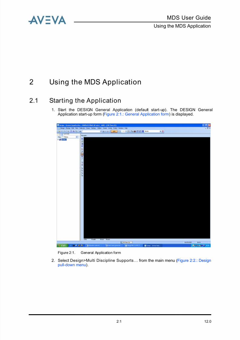
1. Start the DESIGN General Application (default start-up). The DESIGN General Application start-up form (Figure 2:1.: General Application form) is displayed.
Figure 2:1. General Application form
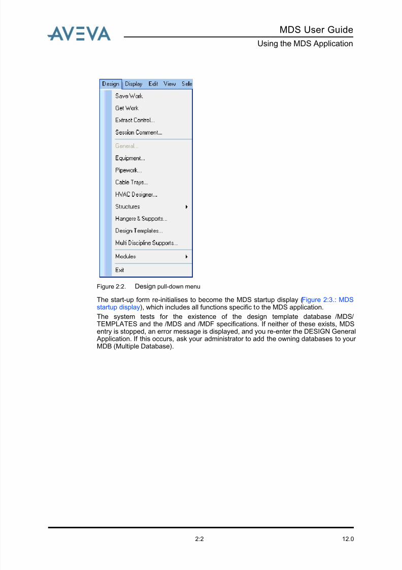
2. Select Design>Multi Discipline Supports… from the main menu (Figure 2:2.: Designpull-down menu).
8/13/2019 Multi-Discipline Supports User Guide
http://slidepdf.com/reader/full/multi-discipline-supports-user-guide 10/125
12.02:2
MDS User Guide
Using the MDS Application
Figure 2:2. Design pull-down menu
The start-up form re-initialises to become the MDS startup display (Figure 2:3.: MDSstartup display), which includes all functions specific to the MDS application.
The system tests for the existence of the design template database /MDS/TEMPLATES and the /MDS and /MDF specifications. If neither of these exists, MDSentry is stopped, an error message is displayed, and you re-enter the DESIGN General Application. If this occurs, ask your administrator to add the owning databases to your MDB (Multiple Database).
8/13/2019 Multi-Discipline Supports User Guide
http://slidepdf.com/reader/full/multi-discipline-supports-user-guide 11/125
MDS User Guide
Using the MDS Application
12.02:3
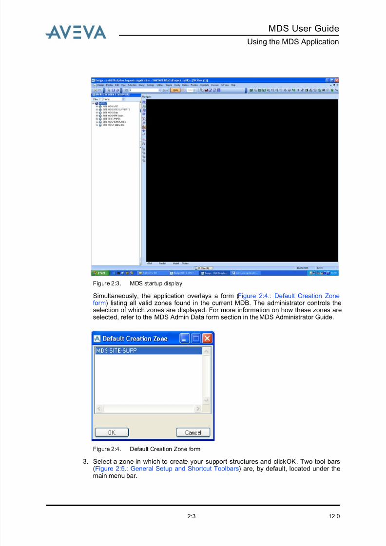
Figure 2:3. MDS startup display
Simultaneously, the application overlays a form (Figure 2:4.: Default Creation Zoneform) listing all valid zones found in the current MDB. The administrator controls theselection of which zones are displayed. For more information on how these zones areselected, refer to the MDS Admin Data form section in the MDS Administrator Guide.
Figure 2:4. Default Creation Zone form
3. Select a zone in which to create your support structures and click OK. Two tool bars(Figure 2:5.: General Setup and Shortcut Toolbars) are, by default, located under the
main menu bar.
8/13/2019 Multi-Discipline Supports User Guide
http://slidepdf.com/reader/full/multi-discipline-supports-user-guide 12/125
12.02:4
MDS User Guide
Using the MDS Application
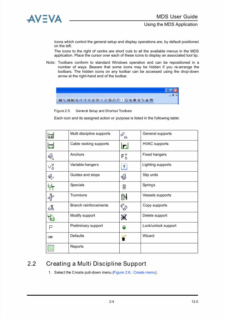
Icons which control the general setup and display operations are, by default positionedon the left.
The icons to the right of centre are short cuts to all the available menus in the MDS
application. Place the cursor over each of these icons to display an associated tool tip.
Note: Toolbars conform to standard Windows operation and can be repositioned in a
number of ways. Beware that some icons may be hidden if you re-arrange the
toolbars. The hidden icons on any toolbar can be accessed using the drop-down
arrow at the right-hand end of the toolbar.
Figure 2:5. General Setup and Shortcut Toolbars
Each icon and its assigned action or purpose is listed in the following table:
2.2 Creating a Mult i Discipline Support
1. Select the Create pull-down menu (Figure 2:6.: Create menu).
Multi discipline supports General supports
Cable racking supports HVAC supports
Anchors Fixed hangers
Variable hangers
Lighting supports
Guides and stops Slip units
Specials Springs
Trunnions Vessels supports
Branch reinforcements Copy supports
Modify support Delete support
Preliminary support Lock/unlock support
Defaults Wizard
Reports

8/13/2019 Multi-Discipline Supports User Guide
http://slidepdf.com/reader/full/multi-discipline-supports-user-guide 13/125
MDS User Guide
Using the MDS Application
12.02:5
Figure 2:6. Create menu
2. Click on Multi Discipline Frame…. A form similar to the example shown in Figure 2:7.:Multi-discipline Frameworks selection form is displayed, listing all the availablesupports for the MDS application.
8/13/2019 Multi-Discipline Supports User Guide
http://slidepdf.com/reader/full/multi-discipline-supports-user-guide 14/125
12.02:6
MDS User Guide
Using the MDS Application
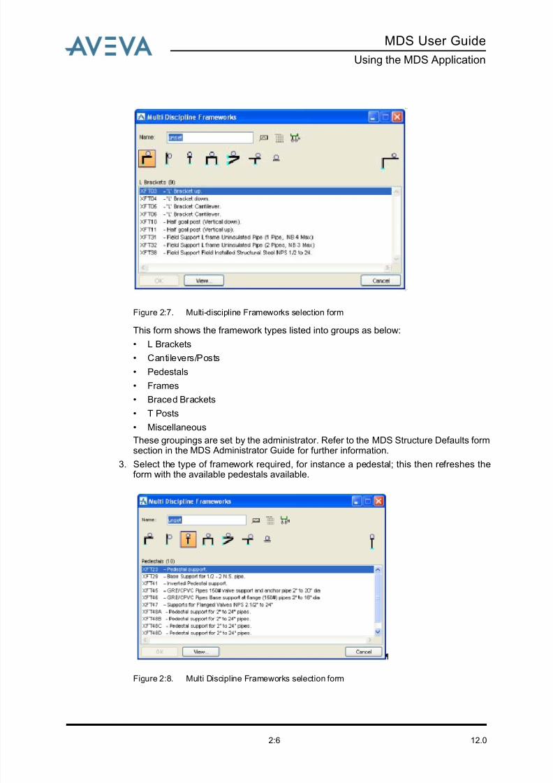
Figure 2:7. Multi-discipline Frameworks selection form
This form shows the framework types listed into groups as below:
• L Brackets
• Cantilevers/Posts
• Pedestals
• Frames
• Braced Brackets
• T Posts
• Miscellaneous
These groupings are set by the administrator. Refer to the MDS Structure Defaults formsection in the MDS Administrator Guide for further information.
3. Select the type of framework required, for instance a pedestal; this then refreshes theform with the available pedestals available.
Figure 2:8. Multi Discipline Frameworks selection form
8/13/2019 Multi-Discipline Supports User Guide
http://slidepdf.com/reader/full/multi-discipline-supports-user-guide 15/125
MDS User Guide
Using the MDS Application
12.02:7
You can also create support groups using the icon. Group names are identified bythe suffix, [1]. Hangers can be added to the main framework support group and detailedas one entire MDS support drawing.
Any available support which requires a different description to be displayed, or requiresa different name to the standard name supplied, can be modified using the MDSStructure Defaults form. Refer to the MDS Administrator Guide for further information.
In the examples shown in Figure 2:7.: Multi-discipline Frameworks selection form, andFigure 2:8.: Multi Discipline Frameworks selection form the prefix X has been added toall support default names.
4. Enter a name as follows:
1. Enter the name of the support to be created.
If you enter a legal name in the Name field then click the OK button, the formbecomes active. Notice that in Figure 2:8.: Multi Discipline Frameworks selectionform, no name is specified and so the OK button is inactive.
or …
2. Click on the AutoName icon at the top of the form. An automatically generatedname is filled in and the OK button becomes active.
5. Click on the required support type.
Note: Do NOT click on OK at this time.
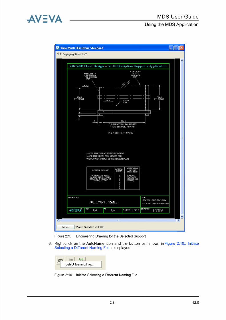
At any time when the Multi Discipline Frameworks form is displayed, you can click onthe View button to see the engineering drawing corresponding to the selected support.See the example in Figure 2:9.: Engineering Drawing for the Selected Support.
8/13/2019 Multi-Discipline Supports User Guide
http://slidepdf.com/reader/full/multi-discipline-supports-user-guide 16/125
12.02:8
MDS User Guide
Using the MDS Application
Figure 2:9. Engineering Drawing for the Selected Support
6. Right-click on the AutoName icon and the button bar shown in Figure 2:10.: InitiateSelecting a Different Naming File is displayed.
Figure 2:10. Initiate Selecting a Different Naming File
8/13/2019 Multi-Discipline Supports User Guide
http://slidepdf.com/reader/full/multi-discipline-supports-user-guide 17/125
MDS User Guide
Using the MDS Application
12.02:9
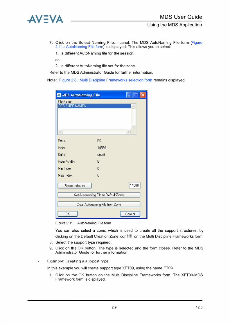
7. Click on the Select Naming File… panel. The MDS AutoNaming File form (Figure2:11.: AutoNaming File form) is displayed. This allows you to select:
1. a different AutoNaming file for the session,
or …
2. a different AutoNaming file set for the zone.
Refer to the MDS Administrator Guide for further information.
Note: Figure 2:8.: Multi Discipline Frameworks selection form remains displayed.
Figure 2:11. AutoNaming File form
You can also select a zone, which is used to create all the support structures, by
clicking on the Default Creation Zone icon on the Multi Discipline Frameworks form.
8. Select the support type required.
9. Click on the OK button. The type is selected and the form closes. Refer to the MDS Administrator Guide for further information.
- Example: Creat ing a support type
In this example you will create support type XFT09, using the name FT09
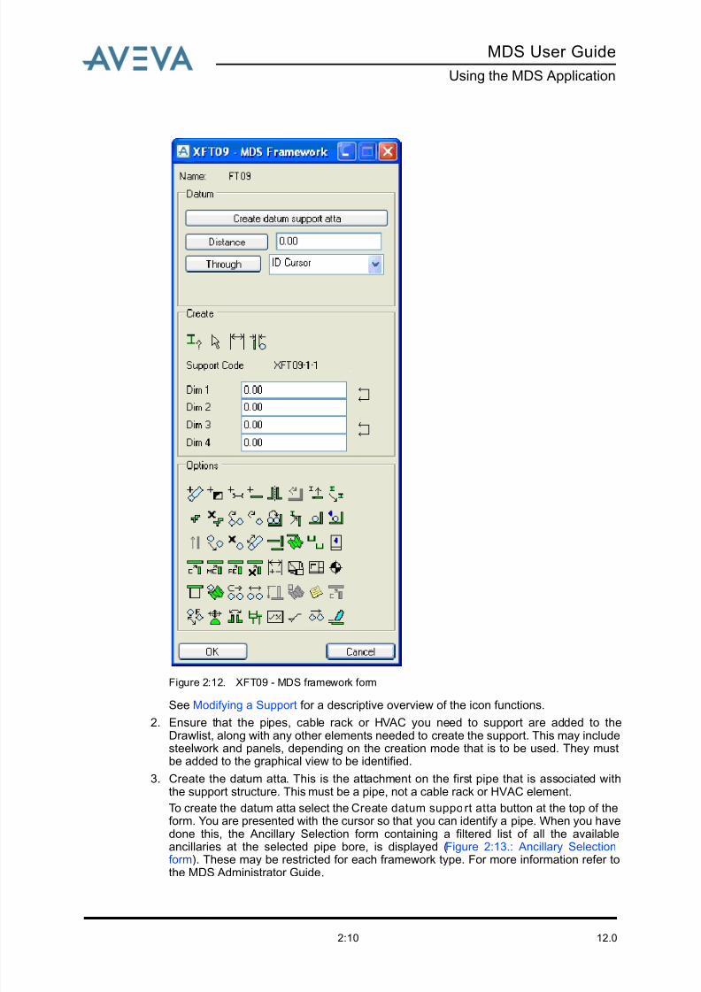
1. Click on the OK button on the Multi Discipline Frameworks form. The XFT09-MDSFramework form is displayed.
8/13/2019 Multi-Discipline Supports User Guide
http://slidepdf.com/reader/full/multi-discipline-supports-user-guide 18/125
12.02:10
MDS User Guide
Using the MDS Application
Figure 2:12. XFT09 - MDS framework form
See Modifying a Support for a descriptive overview of the icon functions.
2. Ensure that the pipes, cable rack or HVAC you need to support are added to theDrawlist, along with any other elements needed to create the support. This may includesteelwork and panels, depending on the creation mode that is to be used. They mustbe added to the graphical view to be identified.
3. Create the datum atta. This is the attachment on the first pipe that is associated withthe support structure. This must be a pipe, not a cable rack or HVAC element.
To create the datum atta select the Create datum support atta button at the top of theform. You are presented with the cursor so that you can identify a pipe. When you havedone this, the Ancillary Selection form containing a filtered list of all the availableancillaries at the selected pipe bore, is displayed (Figure 2:13.: Ancillary Selectionform). These may be restricted for each framework type. For more information refer to
the MDS Administrator Guide.
8/13/2019 Multi-Discipline Supports User Guide
http://slidepdf.com/reader/full/multi-discipline-supports-user-guide 19/125
MDS User Guide
Using the MDS Application
12.02:11
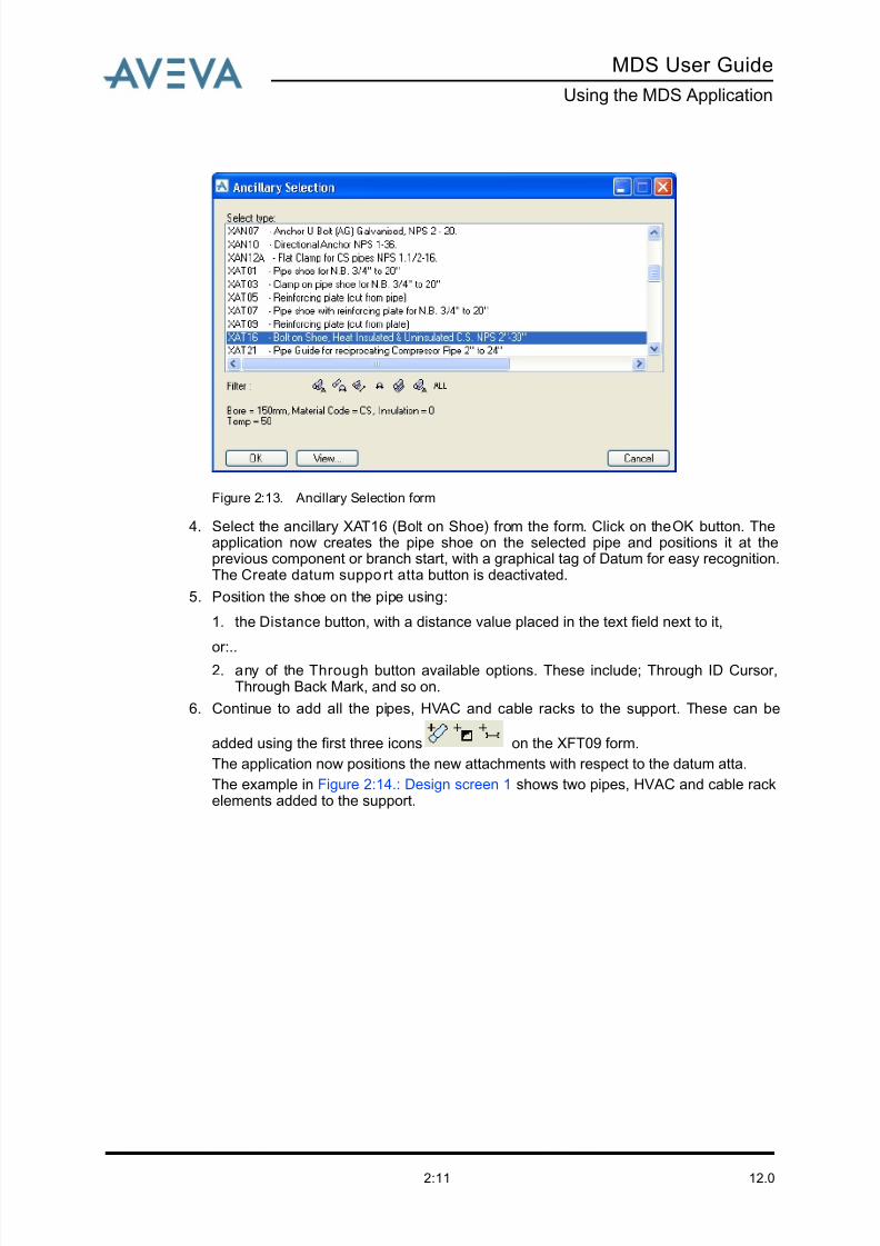
Figure 2:13. Ancillary Selection form
4. Select the ancillary XAT16 (Bolt on Shoe) from the form. Click on the OK button. Theapplication now creates the pipe shoe on the selected pipe and positions it at theprevious component or branch start, with a graphical tag of Datum for easy recognition.The Create datum support atta button is deactivated.
5. Position the shoe on the pipe using:
1. the Distance button, with a distance value placed in the text field next to it,
or:..
2. any of the Through button available options. These include; Through ID Cursor,Through Back Mark, and so on.
6. Continue to add all the pipes, HVAC and cable racks to the support. These can be
added using the first three icons on the XFT09 form.
The application now positions the new attachments with respect to the datum atta.
The example in Figure 2:14.: Design screen 1 shows two pipes, HVAC and cable rackelements added to the support.
8/13/2019 Multi-Discipline Supports User Guide
http://slidepdf.com/reader/full/multi-discipline-supports-user-guide 20/125
12.02:12
MDS User Guide
Using the MDS Application
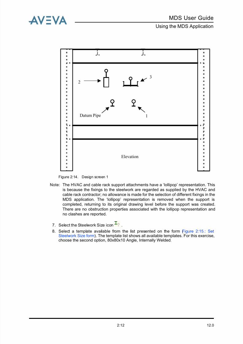
Figure 2:14. Design screen 1
Note: The HVAC and cable rack support attachments have a ‘lollipop’ representation. This
is because the fixings to the steelwork are regarded as supplied by the HVAC and
cable rack contractor; no allowance is made for the selection of different fixings in the
MDS application. The ‘lollipop’ representation is removed when the support is
completed, returning to its original drawing level before the support was created.
There are no obstruction properties associated with the lollipop representation and
no clashes are reported.
7. Select the Steelwork Size icon .
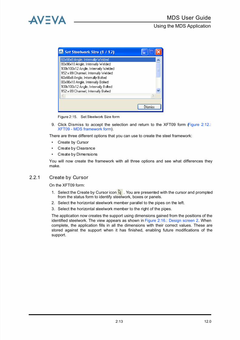
8. Select a template available from the list presented on the form (Figure 2:15.: SetSteelwork Size form). The template list shows all available templates. For this exercise,
choose the second option, 80x80x10 Angle, Internally Welded.
Elevation
Datum Pipe 1
3
2
8/13/2019 Multi-Discipline Supports User Guide
http://slidepdf.com/reader/full/multi-discipline-supports-user-guide 21/125
MDS User Guide
Using the MDS Application
12.02:13
Figure 2:15. Set Steelwork Size form
9. Click Dismiss to accept the selection and return to the XFT09 form (Figure 2:12.:XFT09 - MDS framework form).
There are three different options that you can use to create the steel framework:
• Create by Cursor
• Create by Clearance
• Create by Dimensions
You will now create the framework with all three options and see what differences they
make.
2.2.1 Create by Cursor On the XFT09 form:
1. Select the Create by Cursor icon . You are presented with the cursor and promptedfrom the status form to identify steelwork, boxes or panels.
2. Select the horizontal steelwork member parallel to the pipes on the left.
3. Select the horizontal steelwork member to the right of the pipes.
The application now creates the support using dimensions gained from the positions of the
identified steelwork. The view appears as shown in Figure 2:16.: Design screen 2. When
complete, the application fills in all the dimensions with their correct values. These are
stored against the support when it has finished, enabling future modifications of the
support.
8/13/2019 Multi-Discipline Supports User Guide
http://slidepdf.com/reader/full/multi-discipline-supports-user-guide 22/125
12.02:14
MDS User Guide
Using the MDS Application
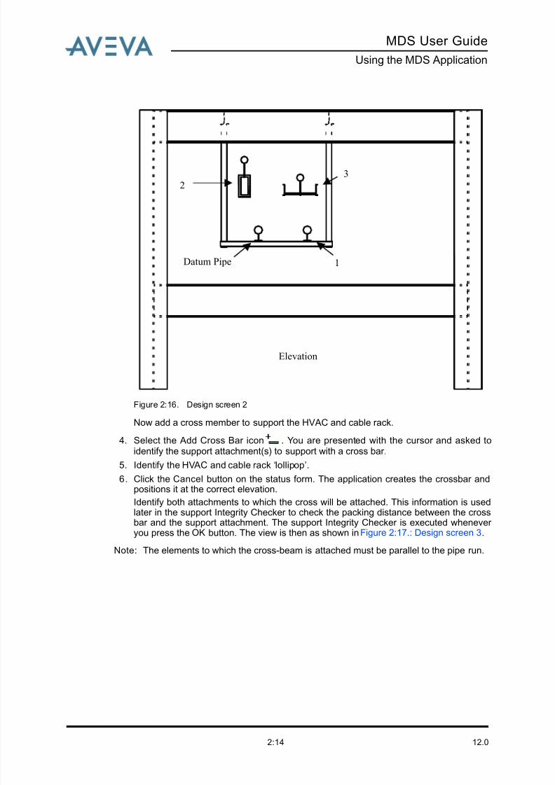
Figure 2:16. Design screen 2
Now add a cross member to support the HVAC and cable rack.
4. Select the Add Cross Bar icon . You are presented with the cursor and asked toidentify the support attachment(s) to support with a cross bar.
5. Identify the HVAC and cable rack ‘lollipop’.
6. Click the Cancel button on the status form. The application creates the crossbar andpositions it at the correct elevation.
Identify both attachments to which the cross will be attached. This information is usedlater in the support Integrity Checker to check the packing distance between the crossbar and the support attachment. The support Integrity Checker is executed whenever you press the OK button. The view is then as shown in Figure 2:17.: Design screen 3.
Note: The elements to which the cross-beam is attached must be parallel to the pipe run.
Elevation
Datum Pipe 1
3
2
8/13/2019 Multi-Discipline Supports User Guide
http://slidepdf.com/reader/full/multi-discipline-supports-user-guide 23/125
8/13/2019 Multi-Discipline Supports User Guide
http://slidepdf.com/reader/full/multi-discipline-supports-user-guide 24/125
12.02:16
MDS User Guide
Using the MDS Application
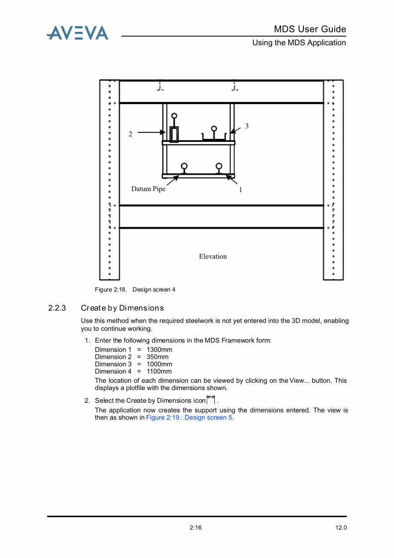
Figure 2:18. Design screen 4
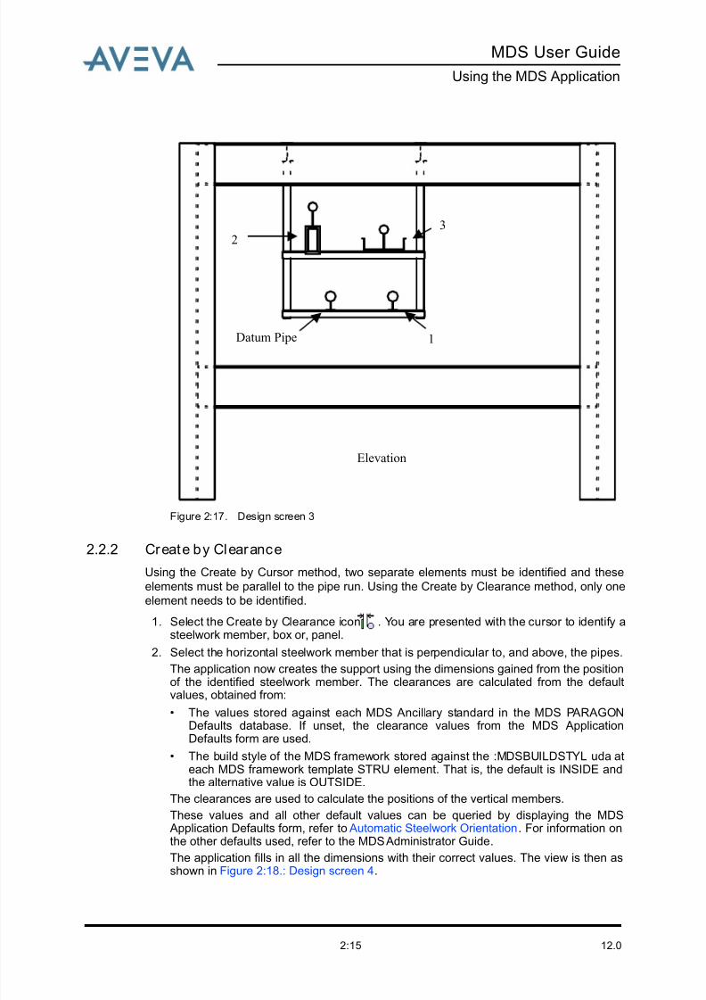
2.2.3 Create by Dimensions
Use this method when the required steelwork is not yet entered into the 3D model, enabling
you to continue working.
1. Enter the following dimensions in the MDS Framework form:
Dimension 1 = 1300mmDimension 2 = 350mmDimension 3 = 1000mmDimension 4 = 1100mm
The location of each dimension can be viewed by clicking on the View... button. This
displays a plotfile with the dimensions shown.2. Select the Create by Dimensions icon .
The application now creates the support using the dimensions entered. The view isthen as shown in Figure 2:19.: Design screen 5.
Elevation
Datum Pipe 1
32
8/13/2019 Multi-Discipline Supports User Guide
http://slidepdf.com/reader/full/multi-discipline-supports-user-guide 25/125
MDS User Guide
Using the MDS Application
12.02:17
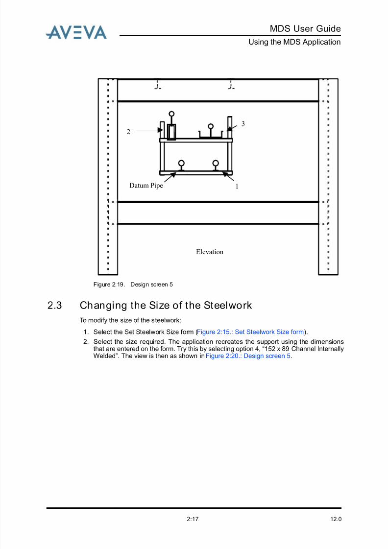
Figure 2:19. Design screen 5
2.3 Changing the Size of the Steelwork
To modify the size of the steelwork:
1. Select the Set Steelwork Size form (Figure 2:15.: Set Steelwork Size form).
2. Select the size required. The application recreates the support using the dimensionsthat are entered on the form. Try this by selecting option 4, “152 x 89 Channel InternallyWelded”. The view is then as shown in Figure 2:20.: Design screen 5.
Elevation
Datum Pipe 1
32

8/13/2019 Multi-Discipline Supports User Guide
http://slidepdf.com/reader/full/multi-discipline-supports-user-guide 26/125
12.02:18
MDS User Guide
Using the MDS Application
Figure 2:20. Design screen 5
2.4 Adding a Packing Piece
Packing pieces are used to make up height differences between the cross bar and support
attachments.
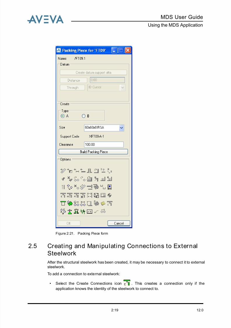
1. Select the Add Packer icon from the MDS XFT09 form. You are presented with thecursor and a status line prompt to identify the support atta to add the packing piece to.The Packing Piece form (Figure 2:21.: Packing Piece form) is displayed.
2. Fill in the form as required.
Elevation
Datum Pipe 1
32
8/13/2019 Multi-Discipline Supports User Guide
http://slidepdf.com/reader/full/multi-discipline-supports-user-guide 27/125
MDS User Guide
Using the MDS Application
12.02:19
Figure 2:21. Packing Piece form
2.5 Creating and Manipulating Connections to External
Steelwork
After the structural steelwork has been created, it may be necessary to connect it to external
steelwork.
To add a connection to external steelwork:
• Select the Create Connections icon . This creates a connection only if the
application knows the identity of the steelwork to connect to.
8/13/2019 Multi-Discipline Supports User Guide
http://slidepdf.com/reader/full/multi-discipline-supports-user-guide 28/125
12.02:20
MDS User Guide
Using the MDS Application
If you used the Create by Cursor or Create by Clearance methods the connection to the
external steelwork is made automatically.
Note: It is essential that you have write access to create SNOD/SJOI elements on the
necessary external steelwork.
The SNOD is represented in the graphical view. The MDS application defaults control the
level at which joists can be made to the external steelwork.
Refer to the MDS Administrator Guide for more details.
1. Select the Modify Connection icon . You are presented with a form that displays allthe available joints.
2. Select the joint for the joints connected to the external steelwork.
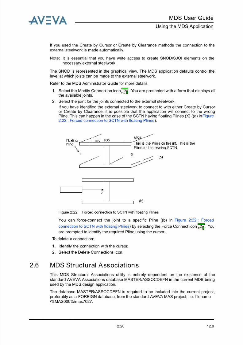
If you have identified the external steelwork to connect to with either Create by Cursor or Create by Clearance, it is possible that the application will connect to the wrongPline. This can happen in the case of the SCTN having floating Plines (X) ((a) in Figure
2:22.: Forced connection to SCTN with floating Plines).
Figure 2:22. Forced connection to SCTN with floating Plines
You can force-connect the joint to a specific Pline ((b) in Figure 2:22.: Forced
connection to SCTN with floating Plines) by selecting the Force Connect icon . You
are prompted to identify the required Pline using the cursor.
To delete a connection:
1. Identify the connection with the cursor.
2. Select the Delete Connections icon.
2.6 MDS Structural Associations
This MDS Structural Associations utility is entirely dependent on the existence of the
standard AVEVA Associations database MASTER/ASSOCDEFN in the current MDB being
used by the MDS design application.
The database MASTER/ASSOCDEFN is required to be included into the current project,
preferably as a FOREIGN database, from the standard AVEVA MAS project, i.e. filename
/%MAS000%/mas7027.

8/13/2019 Multi-Discipline Supports User Guide
http://slidepdf.com/reader/full/multi-discipline-supports-user-guide 29/125
MDS User Guide
Using the MDS Application
12.02:21
The standard AVEVA Associations Manager form also interfaces with the MDS Structural
Associations utility.
The MDS Structural Associations are generated either automatically or manually, depending
on the mode of creation/modification of the MDS support.
2.6.1 Automatically Generated MDS Structural Associations
The MDS Structural Associations are created automatically during the creation/modification
of a MDS standard framework support structure, when the creation mode used is Cursor
or Clearance , and the user graphically identifies the main structural element(s)
from which the MDS structure SCTN element(s) will be supported.
The figure below shows a typical MDS support created by Cursor :
Figure 2:23. MDS Support created by cursor
The MDS Structural Associations are automatically generated for the MDS support, shown
in the picture above, in a ASSOWL element created automatically and named to reflect the
SITE name where the MDS supports are being created, i.e. the ASSOWL name will follow
the convention <sitename>-MDS-ASSOWL.
The figure below shows the typical hierarchy of the MDS supports ZONE and their structural
associations ASSOWL:

8/13/2019 Multi-Discipline Supports User Guide
http://slidepdf.com/reader/full/multi-discipline-supports-user-guide 30/125
12.02:22
MDS User Guide
Using the MDS Application
Figure 2:24. Typical MDS hierarchy
A similar hierarchy to one shown above would also exist for the automatically generated
associations when creating the MDS Support by Clearance
8/13/2019 Multi-Discipline Supports User Guide
http://slidepdf.com/reader/full/multi-discipline-supports-user-guide 31/125
MDS User Guide
Using the MDS Application
12.02:23
2.6.2 Manually Generated MDS Structural Associations
The MDS Structural Associations will not be created automatically during the creation/
modification of a MDS standard framework support structure, when the creation mode used
is by Dimensions .
When a MDS support is created by Dimensions , any existing MDS Structural
Associations (ASSOC elements) for the MDS support will be deleted, but the owning
Association Group, ASSOGP element for the MDS support will remain.
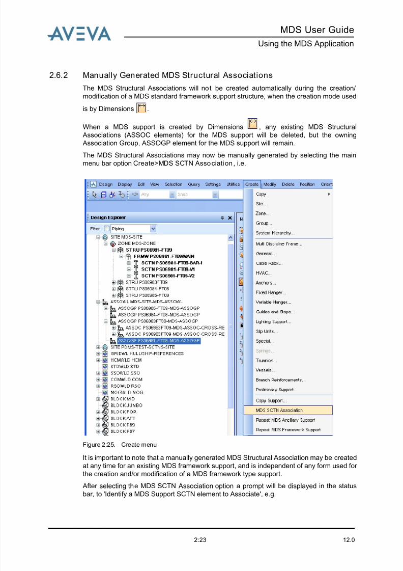
The MDS Structural Associations may now be manually generated by selecting the main
menu bar option Create>MDS SCTN Association , i.e.
Figure 2:25. Create menu
It is important to note that a manually generated MDS Structural Association may be created
at any time for an existing MDS framework support, and is independent of any form used for
the creation and/or modification of a MDS framework type support.
After selecting the MDS SCTN Association option a prompt will be displayed in the status
bar, to 'Identify a MDS Support SCTN element to Associate', e.g.
8/13/2019 Multi-Discipline Supports User Guide
http://slidepdf.com/reader/full/multi-discipline-supports-user-guide 32/125
12.02:24
MDS User Guide
Using the MDS Application
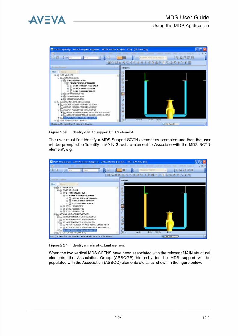
Figure 2:26. Identify a MDS support SCTN element
The user must first identify a MDS Support SCTN element as prompted and then the user
will be prompted to 'Identify a MAIN Structure element to Associate with the MDS SCTN
element', e.g.
Figure 2:27. Identify a main structural element
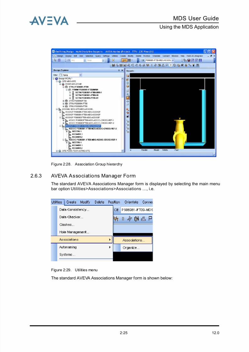
When the two vertical MDS SCTNS have been associated with the relevant MAIN structural
elements, the Association Group (ASSOGP) hierarchy for the MDS support will be
populated with the Association (ASSOC) elements etc…, as shown in the figure below:
8/13/2019 Multi-Discipline Supports User Guide
http://slidepdf.com/reader/full/multi-discipline-supports-user-guide 33/125
MDS User Guide
Using the MDS Application
12.02:25
Figure 2:28. Association Group hierarchy
2.6.3 AVEVA Associations Manager Form
The standard AVEVA Associations Manager form is displayed by selecting the main menubar option Utilities>Associations>Associations …, i.e.
Figure 2:29. Utilities menu
The standard AVEVA Associations Manager form is shown below:
8/13/2019 Multi-Discipline Supports User Guide
http://slidepdf.com/reader/full/multi-discipline-supports-user-guide 34/125
12.02:26
MDS User Guide
Using the MDS Application
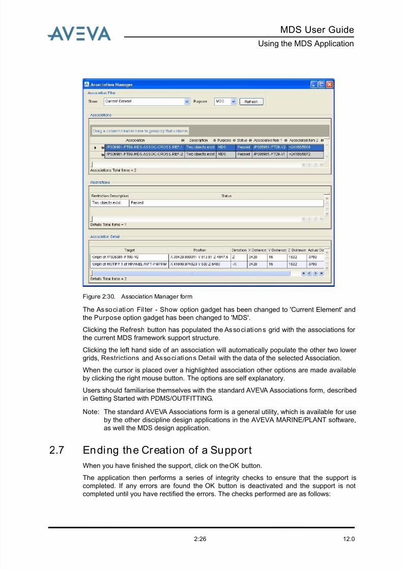
Figure 2:30. Association Manager form
The Association Fil ter - Show option gadget has been changed to 'Current Element' and
the Purpose option gadget has been changed to 'MDS'.
Clicking the Refresh button has populated the Associations grid with the associations for
the current MDS framework support structure.
Clicking the left hand side of an association will automatically populate the other two lower
grids, Restrictions and Associations Detail with the data of the selected Association.
When the cursor is placed over a highlighted association other options are made available
by clicking the right mouse button. The options are self explanatory.
Users should familiarise themselves with the standard AVEVA Associations form, described
in Getting Started with PDMS/OUTFITTING.
Note: The standard AVEVA Associations form is a general utility, which is available for use
by the other discipline design applications in the AVEVA MARINE/PLANT software,
as well the MDS design application.
2.7 Ending the Creation of a Support
When you have finished the support, click on the OK button.
The application then performs a series of integrity checks to ensure that the support is
completed. If any errors are found the OK button is deactivated and the support is not
completed until you have rectified the errors. The checks performed are as follows:

8/13/2019 Multi-Discipline Supports User Guide
http://slidepdf.com/reader/full/multi-discipline-supports-user-guide 35/125
MDS User Guide
Using the MDS Application
12.02:27
- Displays a message
• If the packing distance is greater than 2mm but not greater than allowable packingdistance.
• If the support is a special, a message is issued to you to create the structural steelwork.
• If no warning or errors are found.
- Disp lays a warning message
• If the maximum length of steelwork is not to be exceeded. In the design templatedatabase each member can be given a maximum length that it may not exceed.
- Disp lays an er ro r message
• If the Application Default maximum packing distance has been exceeded.
• If any of the support attachments overlap the crossbar. A maximum overlap value is seton the MDS Application Defaults form (see Viewing the Application Defaults).
• If any of the dimensions associated with the support ancillaries, for example shoes,exceed the values defined in the MDS Ancillary Defaults form (refer to MDS
Administrator Guide).
• If any reference used within the MDS application, for example bedplate reference, nolonger exists.
2.8 Modifying a Support
You can now modify the support using the various options available on the MDS XFT09
support form (Figure 2:12.: XFT09 - MDS framework form). A description of each option,
along with its associated icon, is shown in the following table. The access to each icon is
dependent on the configuration being used. Icons for unavailable options are greyed out.
Mirror framework mirrors the support, perpendicular to the datum
attachment, repositioning the framework members through the structure
origin.
Al ign suppor t picks two points with the EDG (Event Driven Graphics)
application. It then calculates the distance between the two points, using the
datum attas leave direction. This allows you to position the support more
accurately.
Modify support section modifies a section belonging to the support with
the standard modify section start/end form. If a section is modified using thisfacility, any future regeneration of the support will not include these
modifications and returns to the default configuration.
Add packer adds packing pieces to support attas that are not sitting directly
on the steelwork.
Delete packer deletes packing pieces already added to the support
framework.
Rotate all attas can be used when the support type is used with vertical
pipes. It rotates all the attachments by the angle entered into the text field
next to the icon.
8/13/2019 Multi-Discipline Supports User Guide
http://slidepdf.com/reader/full/multi-discipline-supports-user-guide 36/125
12.02:28
MDS User Guide
Using the MDS Application
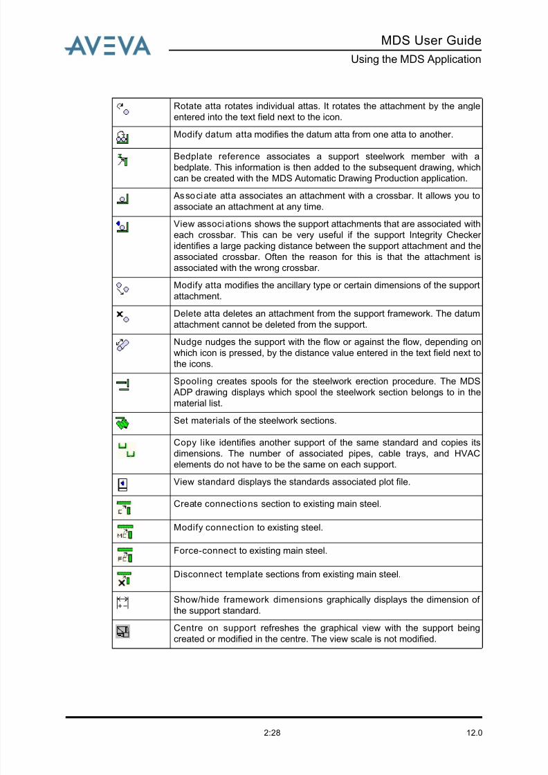
Rotate atta rotates individual attas. It rotates the attachment by the angle
entered into the text field next to the icon.
Modify datum atta modifies the datum atta from one atta to another.
Bedplate reference associates a support steelwork member with a
bedplate. This information is then added to the subsequent drawing, which
can be created with the MDS Automatic Drawing Production application.
Associate atta associates an attachment with a crossbar. It allows you to
associate an attachment at any time.
View associations shows the support attachments that are associated with
each crossbar. This can be very useful if the support Integrity Checker
identifies a large packing distance between the support attachment and the
associated crossbar. Often the reason for this is that the attachment is
associated with the wrong crossbar.Modify atta modifies the ancillary type or certain dimensions of the support
attachment.
Delete atta deletes an attachment from the support framework. The datum
attachment cannot be deleted from the support.
Nudge nudges the support with the flow or against the flow, depending on
which icon is pressed, by the distance value entered in the text field next to
the icons.
Spooling creates spools for the steelwork erection procedure. The MDS
ADP drawing displays which spool the steelwork section belongs to in the
material list.Set materials of the steelwork sections.
Copy like identifies another support of the same standard and copies its
dimensions. The number of associated pipes, cable trays, and HVAC
elements do not have to be the same on each support.
View standard displays the standards associated plot file.
Create connections section to existing main steel.
Modify connection to existing steel.
Force-connect to existing main steel.
Disconnect template sections from existing main steel.
Show/hide framework dimensions graphically displays the dimension of
the support standard.
Centre on support refreshes the graphical view with the support being
created or modified in the centre. The view scale is not modified.
8/13/2019 Multi-Discipline Supports User Guide
http://slidepdf.com/reader/full/multi-discipline-supports-user-guide 37/125
MDS User Guide
Using the MDS Application
12.02:29
To modify a support:
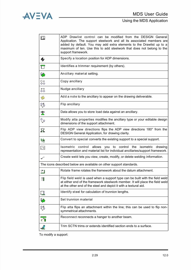
ADP Drawlist cont ro l can be modified from the DESIGN General
Application. The support steelwork and all its associated members are
added by default. You may add extra elements to the Drawlist up to a
maximum of ten. Use this to add steelwork that does not belong to thesupport framework.
Specify a location position for ADP dimensions.
Identifies a trimmer requirement (by others).
Anci llary material setting.
Copy ancillary
Nudge ancillary
Add a note to the ancillary to appear on the drawing deliverable.
Flip ancillary
Data allows you to store load data against an ancillary.
Modify atta properties modifies the ancillary type or your editable design
dimensions of the support attachment.
Flip ADP view directions flips the ADP view directions 180° from the
DESIGN General Application, for drawing clarity.
Convert to special converts the existing support to a special support.
Isometric control allows you to control the isometric drawing
representation and material list for individual ancillaries/support framework.
Create weld lets you view, create, modify, or delete welding information.
The icons described below are available on other support standards.
Rotate frame rotates the framework about the datum attachment.
Flip field weld is used when a support type can be built with the field weld
at either end of the framework steelwork member. It will place the field weld
at the other end of the steel and depict it with a textural aid.
Identify steel for calculation of trunnion lengths.
Set trunnion material
Flip atta flips an attachment within the line; this can be used to flip non-
symmetrical attachments.
Reconnect reconnects a hanger to another beam.
Trim SCTN trims or extends identified section ends to a surface.
8/13/2019 Multi-Discipline Supports User Guide
http://slidepdf.com/reader/full/multi-discipline-supports-user-guide 38/125
12.02:30
MDS User Guide
Using the MDS Application
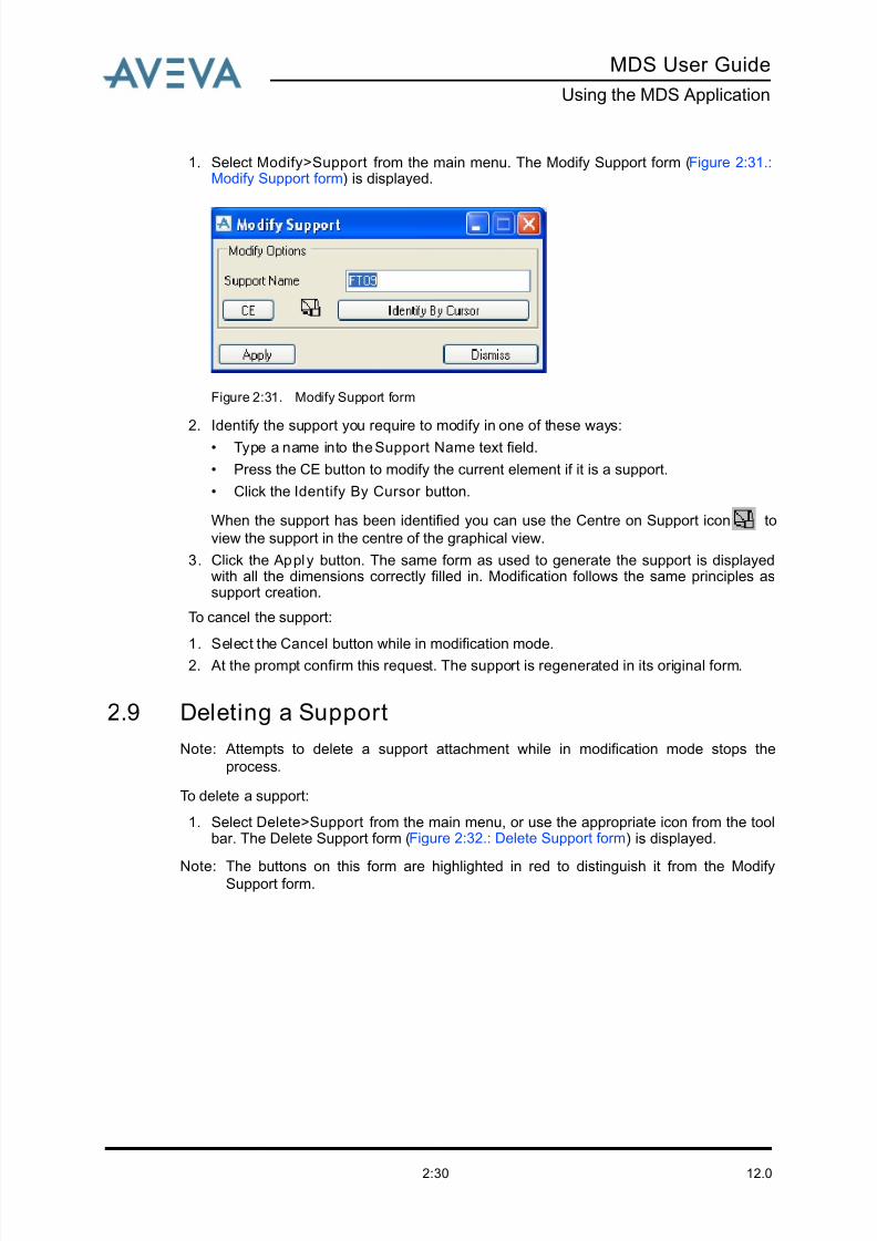
1. Select Modify>Support from the main menu. The Modify Support form (Figure 2:31.:Modify Support form) is displayed.
Figure 2:31. Modify Support form
2. Identify the support you require to modify in one of these ways:
• Type a name into the Support Name text field.
• Press the CE button to modify the current element if it is a support.
• Click the Identify By Cursor button.
When the support has been identified you can use the Centre on Support icon to
view the support in the centre of the graphical view.
3. Click the Apply button. The same form as used to generate the support is displayedwith all the dimensions correctly filled in. Modification follows the same principles assupport creation.
To cancel the support:
1. Select the Cancel button while in modification mode.
2. At the prompt confirm this request. The support is regenerated in its original form.
2.9 Deleting a Support
Note: Attempts to delete a support attachment while in modification mode stops the
process.
To delete a support:
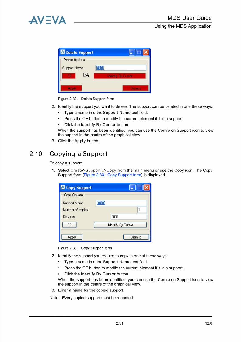
1. Select Delete>Support from the main menu, or use the appropriate icon from the toolbar. The Delete Support form (Figure 2:32.: Delete Support form) is displayed.
Note: The buttons on this form are highlighted in red to distinguish it from the ModifySupport form.
8/13/2019 Multi-Discipline Supports User Guide
http://slidepdf.com/reader/full/multi-discipline-supports-user-guide 39/125
8/13/2019 Multi-Discipline Supports User Guide
http://slidepdf.com/reader/full/multi-discipline-supports-user-guide 40/125
12.02:32
MDS User Guide
Using the MDS Application
4. Enter the number of copies required.
5. Enter the distance to copy the support.
6. Click Apply and then click Yes at the Retain the Copy prompt to accept.
2.11 Repeating a Support
MDS allows you to repeat a support from one line (pipe) to another. This is possible for
standalone ancillaries and support frames only; the repeat function is not available for
trunnions and hangers. (note this differs from the Copying a Support function). Two repeat
functions are available: one is used for repeating a standalone ancillary, the other for
repeating a support frame.
2.11.1 Repeat a Standalone Ancillary
To repeat a standalone ancillary:1. Select Create>Repeat MDS Ancillary Support from the main menu.
A prompt is displayed at the bottom of the main window: ‘Identify MDS Ancillary toRepeat’.
2. Click on the ancillary that you want to repeat. Any atta that has been created by theMDS application can be selected, even if it is a member of a support frame, exceptHVAC and cable rack supports. After selection the atta is validated, and if it does notmatch the conditions above, you are prompted to select another atta until you pick onethat does meet with conditions.
After the atta has been validated, a prompt is displayed at the bottom of the mainwindow: Identify tube of pipe to Add Ancillary.
3. Click on the piece of tube of any pipe where you want to create a copy of the source
atta. When the atta is created, MDS performs the checks that are made when creatingan ancillary, to ensure that it is suitable for the selected tube (material, insulation,temperature and elevation).
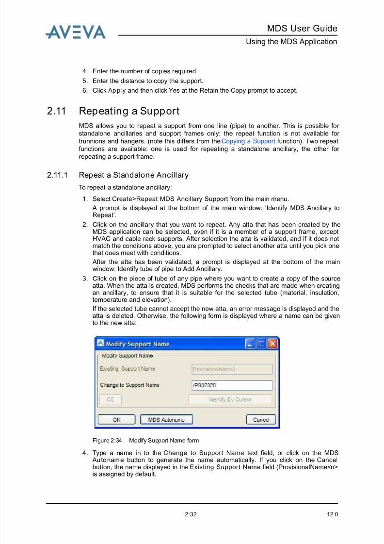
If the selected tube cannot accept the new atta, an error message is displayed and theatta is deleted. Otherwise, the following form is displayed where a name can be givento the new atta:
Figure 2:34. Modify Support Name form
4. Type a name in to the Change to Support Name text field, or click on the MDS Au toname button to generate the name automatically. If you click on the Cancelbutton, the name displayed in the Existing Support Name field (ProvisionalName<n>
is assigned by default.
8/13/2019 Multi-Discipline Supports User Guide
http://slidepdf.com/reader/full/multi-discipline-supports-user-guide 41/125
MDS User Guide
Using the MDS Application
12.02:33
5. Click on the OK button to apply the name change.
6. The repeat function works in a loop: each time a new atta is created you are asked toidentify another tube for which an atta is required.
To exit the procedure, press the Esc key on the keyboard.
2.11.2 Repeat Support Frame
To repeat a support frame:
1. Select Create>Repeat MDS Framework Support from the main menu.
A prompt is displayed at the bottom of the main window: ‘Identify MDS Support Frameto Repeat’.
2. Click on the support frame that is to be repeated. Any member of a frame that has beencreated by the MDS application can be selected (atta, section, joints, etc). After selection the support frame is validated, and if it is not suitable (see ‘Limitations’ below,you are prompted to select another support frame until you pick one that does meet the
conditions.
Note that frames for HVAC and cable racks can be selected.
After the support frame has been validated, a prompt is displayed at the bottom of themain window: ‘Identify tube of pipe to Add Datum Atta of the Support Frame’.
3. Click on the piece of tube (or HVAC/tray section) where you want to create a copy of the source frame. Only the datum atta and SREF atta are copied; any other attas andadditional crossbars are not copied.
When the new frame is created, MDS performs the checks that are made whencreating a support, to ensure it is suitable for the selected tube/HVAC/tray section(bore, steelwork size, orientation).
If the selected tube, etc cannot accept the new support frame, an error message isdisplayed and the frame is deleted. Otherwise, the Modify Support Name form is
displayed so that you can give a name to the new frame. This is the same form that isdisplayed when repeating a standalone ancillary.
4. Type a name for the new frame, or use the MDS Autoname button, then click on OK.Click on Cancel to use the default name.
5. The repeat function works in a loop: each time a new frame is created you are asked toidentify another tube/HVAC/tray section for which a support frame is required.
To exit the procedure, press the Esc key on the keyboard.
Limitations
• If the frame FT22 (bedplate) is selected the procedure is terminated, and the standardform for copying of supports is displayed instead. (see Copying a Support).
• The above repeat functions cannot be used for some frames, as they require specialtreatment. They are:
FT30 FT55A
FT44 FT55B
FT45 FT55C
FT46 FT55D
FT47 VT01 to VT06
FT54A VT20 to VT24
8/13/2019 Multi-Discipline Supports User Guide
http://slidepdf.com/reader/full/multi-discipline-supports-user-guide 42/125
12.02:34
MDS User Guide
Using the MDS Application
2.12 Modifying an Ancil lary Type
To modify an ancillary type:
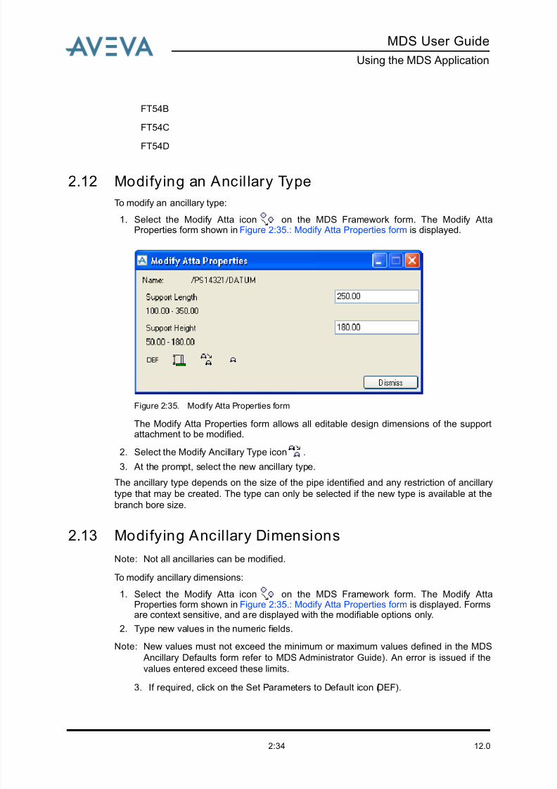
1. Select the Modify Atta icon on the MDS Framework form. The Modify AttaProperties form shown in Figure 2:35.: Modify Atta Properties form is displayed.
Figure 2:35. Modify Atta Properties form
The Modify Atta Properties form allows all editable design dimensions of the supportattachment to be modified.
2. Select the Modify Ancillary Type icon .
3. At the prompt, select the new ancillary type.
The ancillary type depends on the size of the pipe identified and any restriction of ancillary
type that may be created. The type can only be selected if the new type is available at the
branch bore size.
2.13 Modifying Ancil lary Dimensions
Note: Not all ancillaries can be modified.
To modify ancillary dimensions:
1. Select the Modify Atta icon on the MDS Framework form. The Modify AttaProperties form shown in Figure 2:35.: Modify Atta Properties form is displayed. Formsare context sensitive, and are displayed with the modifiable options only.
2. Type new values in the numeric fields.
Note: New values must not exceed the minimum or maximum values defined in the MDS
Ancillary Defaults form refer to MDS Administrator Guide). An error is issued if the
values entered exceed these limits.
3. If required, click on the Set Parameters to Default icon (DEF).
FT54B
FT54C
FT54D

8/13/2019 Multi-Discipline Supports User Guide
http://slidepdf.com/reader/full/multi-discipline-supports-user-guide 43/125
MDS User Guide
Using the MDS Application
12.02:35
Note: The MDS application allows the creation of ancillary standards with their own
geometry. This is an administrator function and is described in the MDS
Administrator Guide.
2.14 Modifying a Support Name
To modify a support name:
1. Select Modify>Support Name… from the main menu. The Modify Support Name form (Figure 2:36.: Modify Support Name form) is displayed.
Figure 2:36. Modify Support Name form
2. Identify the support you require to modify in one of these ways:
• Type a name into the Existing Support Name text field.
• Press the CE button to modify the current element if it is a support.• Click the Identify By Cursor button.
3. Enter the new support name into the Change to Support Name text field.
4. Click on the Apply button.
2.15 Automatic Steelwork Orientation
MDS can automatically orientate the support structure steel members of a framework type
support, dependant on the orientation of identified stiffeners. This function is available when
you create a framework using the Create by Cursor method within the framework creation
process. A typical example of a support frame (FT08) is shown in Figure 2:37.: Example of
Steelwork Orientation.

8/13/2019 Multi-Discipline Supports User Guide
http://slidepdf.com/reader/full/multi-discipline-supports-user-guide 44/125
12.02:36
MDS User Guide
Using the MDS Application
Figure 2:37. Example of Steelwork Orientation
The correct orientation is achieved by utilising appropriate templates. Each standard
template has four alternatives as depicted above. The names of the alternative templates
are followed by a suffix, which is a configuration code based on the orientation of the
stiffeners as depicted. Only templates that are built up from angle profiles have oriented
alternatives.
The MDS Template Catalogue has left and right hand versions of a template. The left hand
version is used when the orientation of the stiffeners is found to be pointing in the same
direction as port, and the right hand version is used for starboard.
To use this feature proceed as follows:
1. On the MDS Framework form. click on the Create by Cursor icon . A prompt isdisplayed at the bottom of the main window asking you to identify the first stiffener, thenthe second stiffener.
2. Identify the stiffeners by clicking on them. MDS then checks that their gtype is angle. If so, the orientation of the stiffener is stored as a number in user-defined attribute (uda):MdsTmplOri at STRU level. The system then checks for the existence of an orientedtemplate with this number; if found, this is used instead of the standard template.
Note: Subsequent modifications of the support by the clearance/dimensions method will
always try to select the oriented template first.
All settings (number of bars, min/max bore, etc) are always obtained from the
standard template, except the value stored in uda :MDSBuildStyl, that is copied
from the alternative.
8/13/2019 Multi-Discipline Supports User Guide
http://slidepdf.com/reader/full/multi-discipline-supports-user-guide 45/125
MDS User Guide
Using the MDS Application
12.02:37
Limitations
Currently, only DIN frames have oriented alternatives, stored in database MDS/DESITMPL-
DIN-ORI of project MDS. These are as follows:
2.16 Viewing the Application Defaults
The MDS designer can modify some of the defaults using the MDS Application Defaults
form. Refer to the User Modified Defaults section in the MDS Administrator Guide.
2.17 Adding a Drawing Note
To add a note to the drawing:
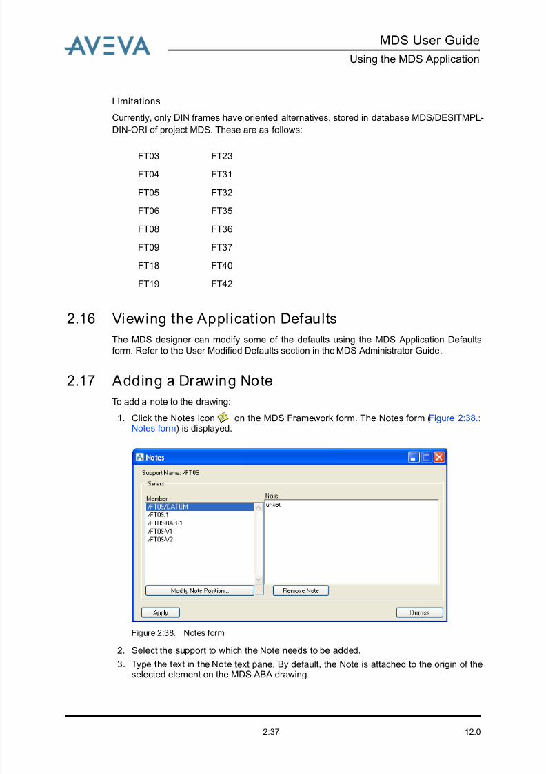
1. Click the Notes icon on the MDS Framework form. The Notes form (Figure 2:38.:Notes form) is displayed.
Figure 2:38. Notes form
2. Select the support to which the Note needs to be added.
3. Type the text in the Note text pane. By default, the Note is attached to the origin of the
selected element on the MDS ABA drawing.
FT03 FT23
FT04 FT31
FT05 FT32
FT06 FT35
FT08 FT36
FT09 FT37
FT18 FT40
FT19 FT42
8/13/2019 Multi-Discipline Supports User Guide
http://slidepdf.com/reader/full/multi-discipline-supports-user-guide 46/125
12.02:38
MDS User Guide
Using the MDS Application
4. Use the Modify Note Position button to attach the Note via EDG (Event DrivenGraphics) to another position on the selected element.
2.18 Adding a Support to the Drawlist
To add all the members of a support to the drawlist:
Select Utilities>Add support(s) from the main menu and then click on one of the following
sub-menu options.
• Explicit: enter the support name into the displayed form.
• Al l Below CE: select CE to add all members below the current element in thehierarchy.
• Al l: add all supports within the current multiple database.
2.19 MDS Administration OptionsThe MDS administration options have been added to assist you. An explanation of each
option and how it can be used is given below.
2.19.1 Reloading Defaults
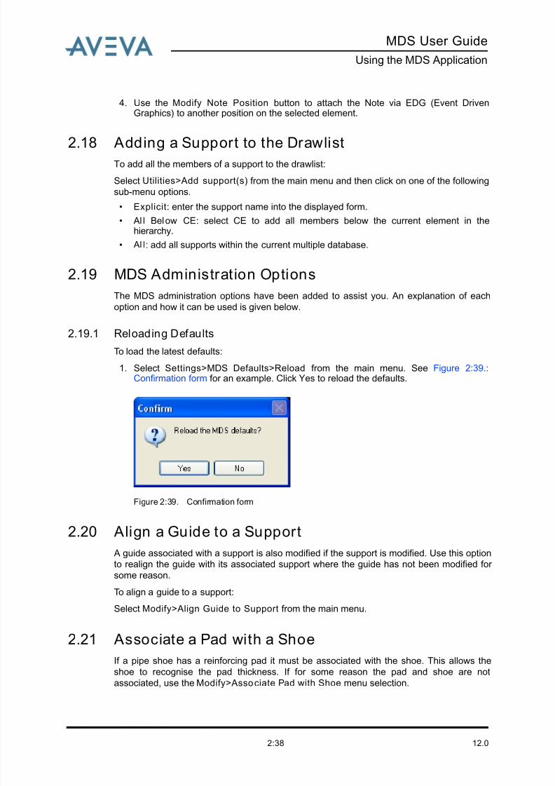
To load the latest defaults:
1. Select Settings>MDS Defaults>Reload from the main menu. See Figure 2:39.:Confirmation form for an example. Click Yes to reload the defaults.
Figure 2:39. Confirmation form
2.20 Align a Guide to a Support
A guide associated with a support is also modified if the support is modified. Use this optionto realign the guide with its associated support where the guide has not been modified for
some reason.
To align a guide to a support:
Select Modify>Align Guide to Support from the main menu.
2.21 Associate a Pad with a Shoe
If a pipe shoe has a reinforcing pad it must be associated with the shoe. This allows the
shoe to recognise the pad thickness. If for some reason the pad and shoe are not
associated, use the Modify>Associate Pad with Shoe menu selection.
8/13/2019 Multi-Discipline Supports User Guide
http://slidepdf.com/reader/full/multi-discipline-supports-user-guide 47/125
MDS User Guide
Using the MDS Application
12.02:39
2.22 Querying the Size of an Ancillary
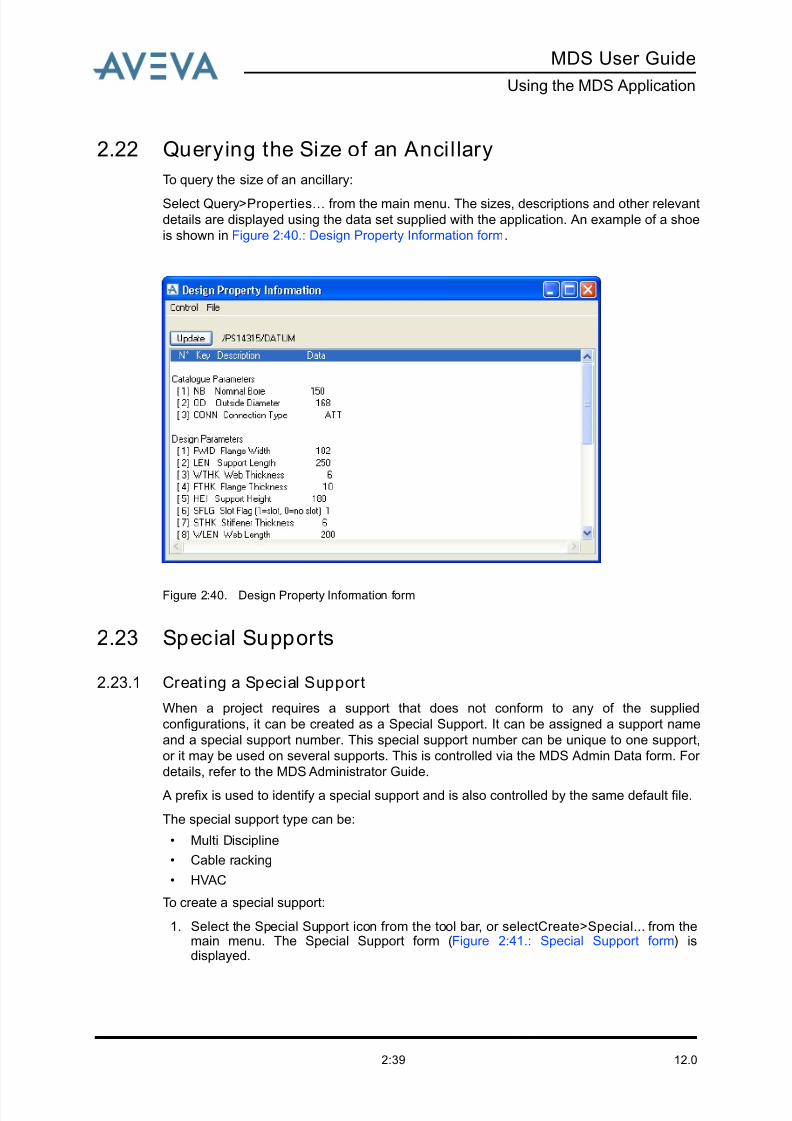
To query the size of an ancillary:
Select Query>Properties…
from the main menu. The sizes, descriptions and other relevant
details are displayed using the data set supplied with the application. An example of a shoe
is shown in Figure 2:40.: Design Property Information form.
Figure 2:40. Design Property Information form
2.23 Special Supports
2.23.1 Creating a Special Support
When a project requires a support that does not conform to any of the supplied
configurations, it can be created as a Special Support. It can be assigned a support name
and a special support number. This special support number can be unique to one support,
or it may be used on several supports. This is controlled via the MDS Admin Data form. For
details, refer to the MDS Administrator Guide.
A prefix is used to identify a special support and is also controlled by the same default file.
The special support type can be:
• Multi Discipline
• Cable racking
• HVAC
To create a special support:
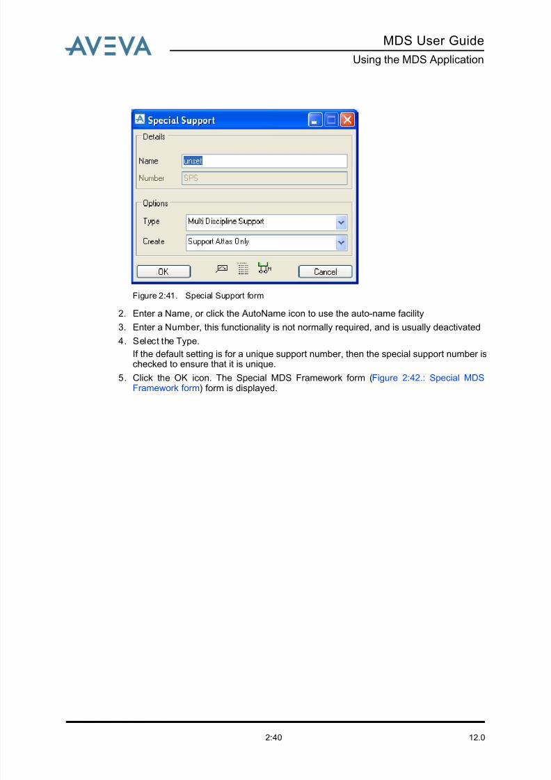
1. Select the Special Support icon from the tool bar, or select Create>Special... from themain menu. The Special Support form (Figure 2:41.: Special Support form) isdisplayed.
8/13/2019 Multi-Discipline Supports User Guide
http://slidepdf.com/reader/full/multi-discipline-supports-user-guide 48/125
12.02:40
MDS User Guide
Using the MDS Application
Figure 2:41. Special Support form
2. Enter a Name, or click the AutoName icon to use the auto-name facility
3. Enter a Number , this functionality is not normally required, and is usually deactivated
4. Select the Type.
If the default setting is for a unique support number, then the special support number ischecked to ensure that it is unique.
5. Click the OK icon. The Special MDS Framework form (Figure 2:42.: Special MDSFramework form) form is displayed.

8/13/2019 Multi-Discipline Supports User Guide
http://slidepdf.com/reader/full/multi-discipline-supports-user-guide 49/125
MDS User Guide
Using the MDS Application
12.02:41
Figure 2:42. Special MDS Framework form
6. Select all the elements to be supported.
7. Position the support in the same way as for the Multi Discipline Support example.
Note: The only difference is that no steelwork sections are automatically created.
8. Click on the OK button.
A minimal check is performed by the support Integrity Checker. A message is displayed inthe support Integrity Check form informing you that you can now use the steelwork
application to create the steelwork members required to complete the support framework.
A structure element is created so that you can create the steelwork within it using the same
name as the support name. The MDS Automatic Drawing Production application produces a
drawing similar to any of the standard support types.
For an overview of the options icon functions refer to the table in Modifying a Support. The
other seven icons are explained in Creating a Project Special Support to Moving an HVAC
Project Special Joint or SCTN.
8/13/2019 Multi-Discipline Supports User Guide
http://slidepdf.com/reader/full/multi-discipline-supports-user-guide 50/125
12.02:42
MDS User Guide
Using the MDS Application
2.23.2 Creating a Special Support from a Combination of MDS StandardFrameworks
The Special Support form can also be used to create a special support from a combinationof existing MDS Standard Frameworks.
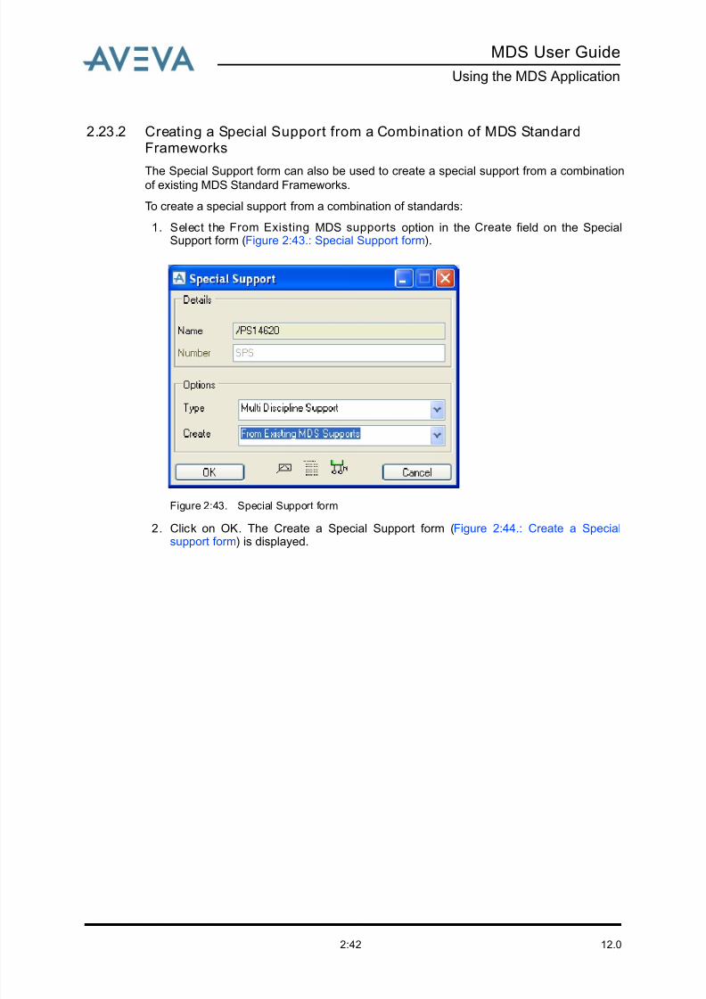
To create a special support from a combination of standards:
1. Select the From Existing MDS supports option in the Create field on the SpecialSupport form (Figure 2:43.: Special Support form).
Figure 2:43. Special Support form
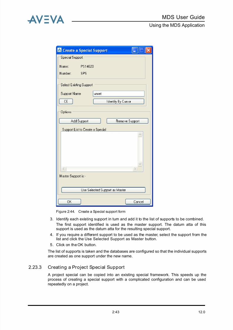
2. Click on OK. The Create a Special Support form (Figure 2:44.: Create a Specialsupport form) is displayed.
8/13/2019 Multi-Discipline Supports User Guide
http://slidepdf.com/reader/full/multi-discipline-supports-user-guide 51/125
8/13/2019 Multi-Discipline Supports User Guide
http://slidepdf.com/reader/full/multi-discipline-supports-user-guide 52/125
12.02:44
MDS User Guide
Using the MDS Application
Project specials are pre-defined in a site called /MDS/SPECIALS. This has three zones
containing the respective special types:
• /MDS/SPECIALS/PIPE
• /MDS/SPECIALS/HVAC
• /MDS/SPECIALS/TRAY
- Project specials for piping - /MDS/SPECIALS/PIPE zone
This zone contains all the available project specials for piping.
1. Select the Support At ta Only option in the Create field on the Special Support form (Figure 2:43.: Special Support form). The Special MDS Framework form (Figure 2:42.:Special MDS Framework form) form is displayed.
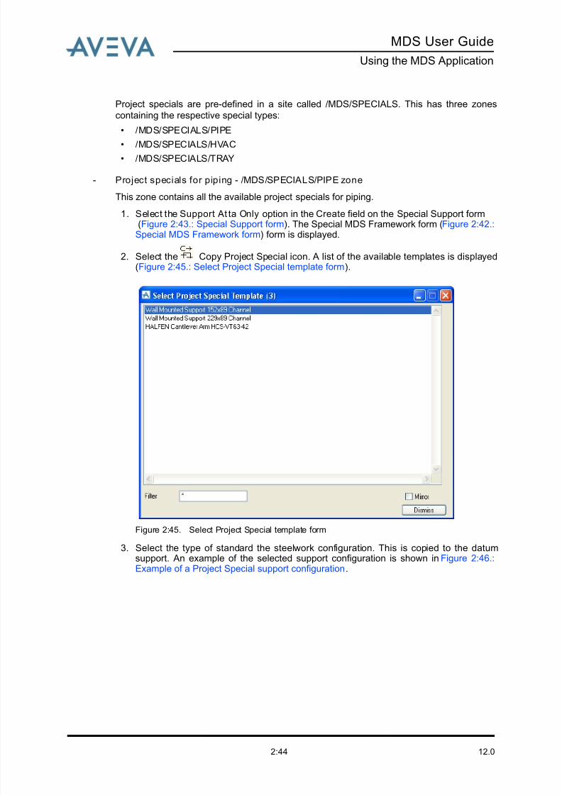
2. Select the Copy Project Special icon. A list of the available templates is displayed(Figure 2:45.: Select Project Special template form).
Figure 2:45. Select Project Special template form
3. Select the type of standard the steelwork configuration. This is copied to the datum
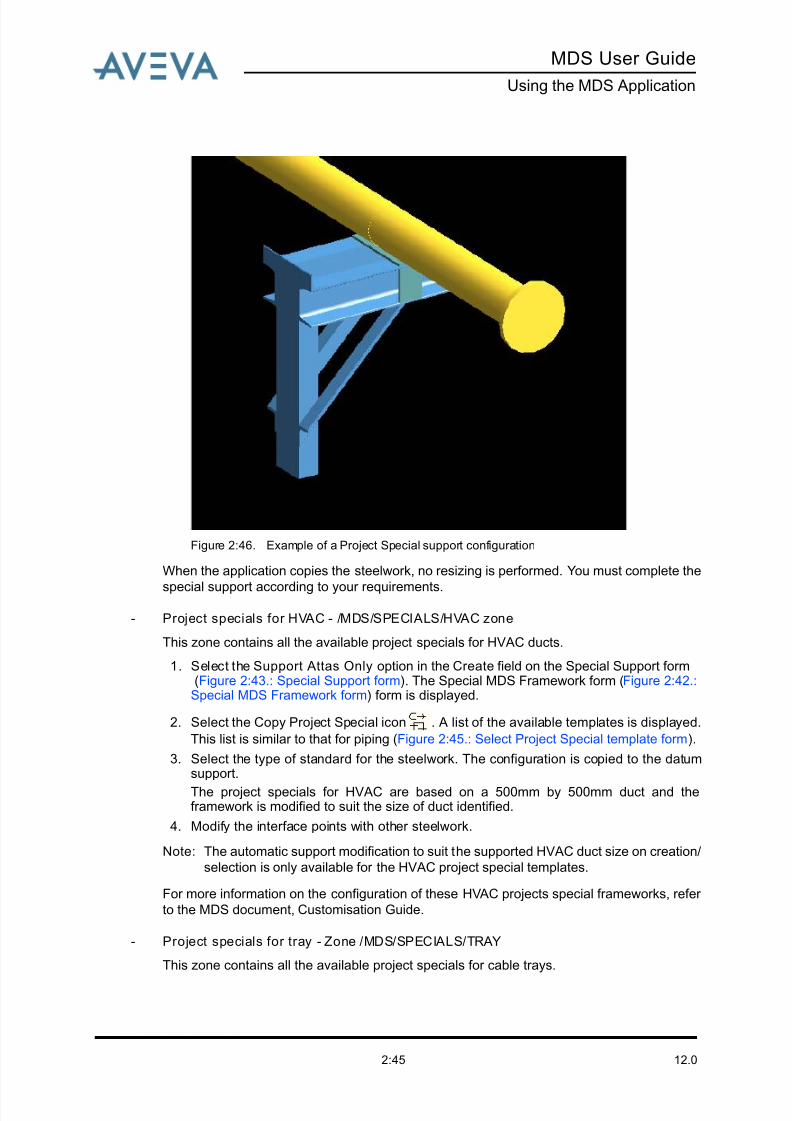
support. An example of the selected support configuration is shown in Figure 2:46.:Example of a Project Special support configuration.
8/13/2019 Multi-Discipline Supports User Guide
http://slidepdf.com/reader/full/multi-discipline-supports-user-guide 53/125
MDS User Guide
Using the MDS Application
12.02:45
Figure 2:46. Example of a Project Special support configuration
When the application copies the steelwork, no resizing is performed. You must complete the
special support according to your requirements.
- Project specials for HVAC - /MDS/SPECIALS/HVAC zone
This zone contains all the available project specials for HVAC ducts.
1. Select the Support Attas Only option in the Create field on the Special Support form (Figure 2:43.: Special Support form). The Special MDS Framework form (Figure 2:42.:Special MDS Framework form) form is displayed.
2. Select the Copy Project Special icon . A list of the available templates is displayed.
This list is similar to that for piping (Figure 2:45.: Select Project Special template form).
3. Select the type of standard for the steelwork. The configuration is copied to the datumsupport.
The project specials for HVAC are based on a 500mm by 500mm duct and theframework is modified to suit the size of duct identified.
4. Modify the interface points with other steelwork.
Note: The automatic support modification to suit the supported HVAC duct size on creation/
selection is only available for the HVAC project special templates.
For more information on the configuration of these HVAC projects special frameworks, refer
to the MDS document, Customisation Guide.
- Project specials for tray - Zone /MDS/SPECIALS/TRAY
This zone contains all the available project specials for cable trays.
8/13/2019 Multi-Discipline Supports User Guide
http://slidepdf.com/reader/full/multi-discipline-supports-user-guide 54/125
8/13/2019 Multi-Discipline Supports User Guide
http://slidepdf.com/reader/full/multi-discipline-supports-user-guide 55/125
MDS User Guide
Using the MDS Application
12.02:47
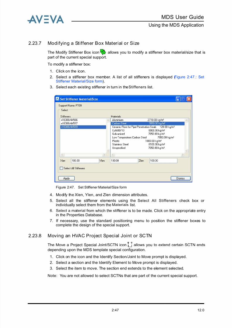
2.23.7 Modifying a Stiffener Box Material or Size
The Modify Stiffener Box icon allows you to modify a stiffener box material/size that is
part of the current special support.
To modify a stiffener box:
1. Click on the icon.
2. Select a stiffener box member. A list of all stiffeners is displayed (Figure 2:47.: SetStiffener Material/Size form).
3. Select each existing stiffener in turn in the Stiffeners list.
Figure 2:47. Set Stiffener Material/Size form
4. Modify the Xlen, Ylen, and Zlen dimension attributes.
5. Select all the stiffener elements using the Select All Stiffeners check box or individually select them from the Materials list.
6. Select a material from which the stiffener is to be made. Click on the appropriate entryin the Properties Database.
7. If necessary, use the standard positioning menu to position the stiffener boxes tocomplete the design of the special support.
2.23.8 Moving an HVAC Project Special Joint or SCTN
The Move a Project Special Joint/SCTN icon allows you to extend certain SCTN ends
depending upon the MDS template special configuration.
1. Click on the icon and the Identify Section/Joint to Move prompt is displayed.
2. Select a section and the Identify Element to Move prompt is displayed.
3. Select the item to move. The section end extends to the element selected.
Note: You are not allowed to select SCTNs that are part of the current special support.
8/13/2019 Multi-Discipline Supports User Guide
http://slidepdf.com/reader/full/multi-discipline-supports-user-guide 56/125
12.02:48
MDS User Guide
Using the MDS Application
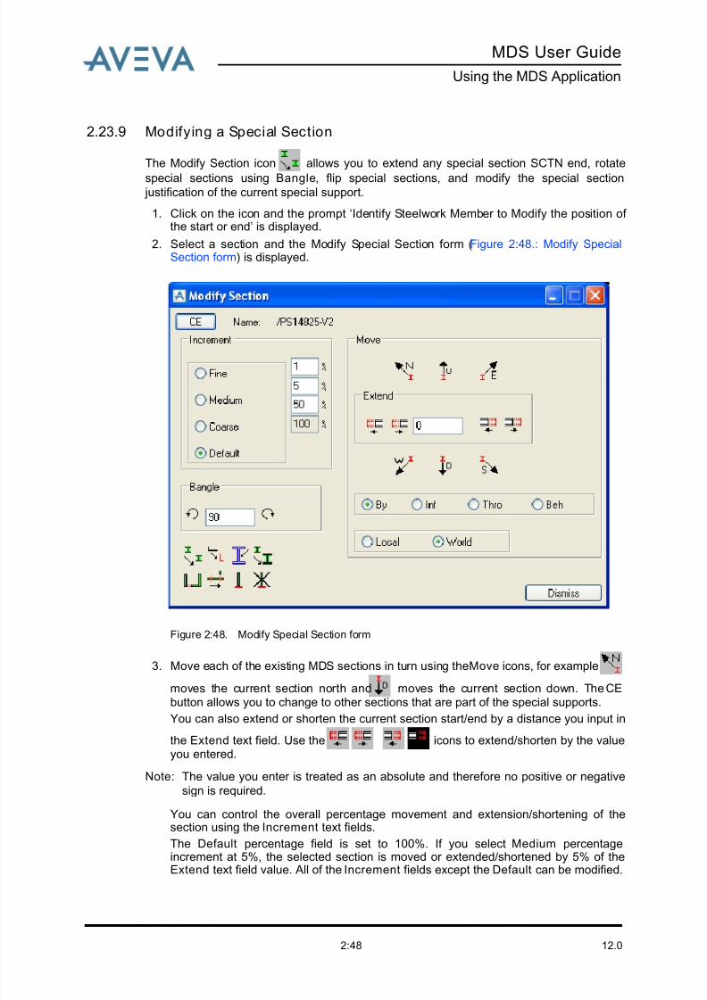
2.23.9 Modifying a Special Section
The Modify Section icon allows you to extend any special section SCTN end, rotate
special sections using Bangle, flip special sections, and modify the special section justification of the current special support.
1. Click on the icon and the prompt ‘Identify Steelwork Member to Modify the position of the start or end’ is displayed.
2. Select a section and the Modify Special Section form (Figure 2:48.: Modify SpecialSection form) is displayed.
Figure 2:48. Modify Special Section form
3. Move each of the existing MDS sections in turn using the Move icons, for example
moves the current section north and moves the current section down. The CE
button allows you to change to other sections that are part of the special supports.You can also extend or shorten the current section start/end by a distance you input in
the Extend text field. Use the icons to extend/shorten by the valueyou entered.
Note: The value you enter is treated as an absolute and therefore no positive or negative
sign is required.
You can control the overall percentage movement and extension/shortening of thesection using the Increment text fields.
The Default percentage field is set to 100%. If you select Medium percentageincrement at 5%, the selected section is moved or extended/shortened by 5% of theExtend text field value. All of the Increment fields except the Default can be modified.
8/13/2019 Multi-Discipline Supports User Guide
http://slidepdf.com/reader/full/multi-discipline-supports-user-guide 57/125
MDS User Guide
Using the MDS Application
12.02:49
4. You can control the overall rotation angle using the Bangle text field. The default valueis 90° and the maximum allowed is 180°.
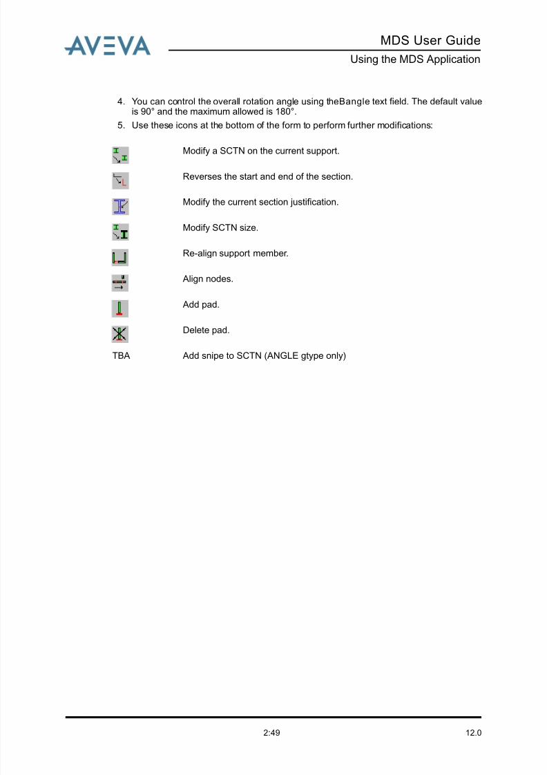
5. Use these icons at the bottom of the form to perform further modifications:
Modify a SCTN on the current support.
Reverses the start and end of the section.
Modify the current section justification.
Modify SCTN size.
Re-align support member.
Align nodes.
Add pad.
Delete pad.
TBA Add snipe to SCTN (ANGLE gtype only)

8/13/2019 Multi-Discipline Supports User Guide
http://slidepdf.com/reader/full/multi-discipline-supports-user-guide 58/125
12.02:50
MDS User Guide
Using the MDS Application

8/13/2019 Multi-Discipline Supports User Guide
http://slidepdf.com/reader/full/multi-discipline-supports-user-guide 59/125
MDS User Guide
Adding Snipes to Steelwork Members
12.03:1
3 Adding Snipes to Steelwork Members
3.1 Description of Snipe Ut il ity
MDS provides the ability to create and modify snipes on support structural members. A
snipe is where a support structural member is cut at an angle, such that a corner is
removed. For example, Figure 3:1.: Snipes added to FT08 framework shows snipes addedto an FT08 framework type.
Figure 3:1. Snipes added to FT08 framework
This feature currently only works with angular sections, i.e. steelwork profiles of type SCTN
and gtype ANG. Two cases are catered for:
• Snipe on end of leg attached to stiffener
• Snipe on free end of section.
3.1.1 Snipe on End of Leg Attached to Stiffener
When the section is attached to a stiffener the following calculations are used, where
SL = Snipe length on the leg of the framework
FL = Length of leg section
M1 = Control gap for back-to-back (default = 10 mm)
M2 = Length in the opposite direction of M1 on flange of stiffener
M3 = Distance between flange top outside edge of stiffener and leg point
connected with the flange top of stiffener (default = 25 mm)
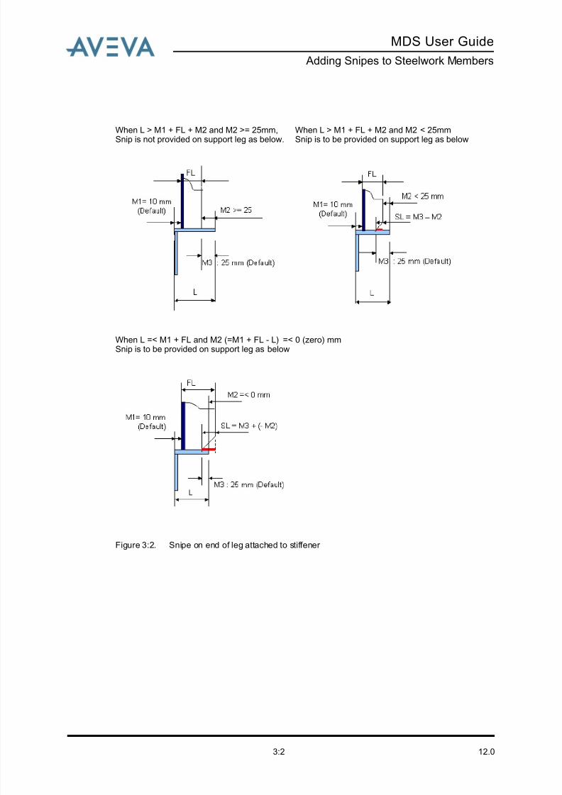
8/13/2019 Multi-Discipline Supports User Guide
http://slidepdf.com/reader/full/multi-discipline-supports-user-guide 60/125
12.03:2
MDS User Guide
Adding Snipes to Steelwork Members
Figure 3:2. Snipe on end of leg attached to stiffener
When L > M1 + FL + M2 and M2 >= 25mm,
Snip is not provided on support leg as below.
When L > M1 + FL + M2 and M2 < 25mm
Snip is to be provided on support leg as below
When L =< M1 + FL and M2 (=M1 + FL - L) =< 0 (zero) mmSnip is to be provided on support leg as below

8/13/2019 Multi-Discipline Supports User Guide
http://slidepdf.com/reader/full/multi-discipline-supports-user-guide 61/125
MDS User Guide
Adding Snipes to Steelwork Members
12.03:3
3.1.2 Snipe on Free End of Section
When the section is not attached to a stiffener the following calculation is used:
Figure 3:3. Snipe on free end of section
3.2 Applicable MDS Templates
The snipes described in Snipe on Free End of Section have been added to angle sections of
all templates in databases MDS/DESITMPL-DIN and MDS/DESITMPL-DIN-ORI. The list of
modified templates is as follows:
3.3 Creating Snipes
Snipes can either be created automatically when an MDS framework is created or modified,or they can be created manually using the Snipes utility.
3.3.1 Automatically Created Snipes
If the support leg is attached to a stiffener and their configuration conforms to Figure 3:2.:
Snipe on end of leg attached to stiffener , snipes are automatically created when an MDS
framework is created or modified (using the MDS Framework form).
The snipe size is automatically calculated as follows:
• When the calculated size is less than the minimum allowable, the snipe is not created.The minimum snipe is set at 10mm and cannot be changed.
• If the calculated size is greater than the maximum, then the maximum size is used
instead. The maximum size depends on the angle section size and is calculated as the
FT03 FT11 FT34A
FT04 FT18 FT34B
FT05 FT19 FT36
FT06 FT21 FT37
FT07 FT29 FT38
FT08 FT31 FT39
FT09 FT32 FT40
FT10 FT33 FT42
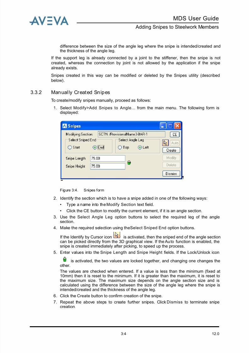
8/13/2019 Multi-Discipline Supports User Guide
http://slidepdf.com/reader/full/multi-discipline-supports-user-guide 62/125
12.03:4
MDS User Guide
Adding Snipes to Steelwork Members
difference between the size of the angle leg where the snipe is intended/created andthe thickness of the angle leg.
If the support leg is already connected by a joint to the stiffener, then the snipe is not
created, whereas the connection by joint is not allowed by the application if the snipealready exists.
Snipes created in this way can be modified or deleted by the Snipes utility (described
below).
3.3.2 Manual ly Created Snipes
To create/modify snipes manually, proceed as follows:
1. Select Modify>Add Snipes to Angle... from the main menu. The following form isdisplayed:
Figure 3:4. Snipes form
2. Identify the section which is to have a snipe added in one of the following ways:
• Type a name into the Modify Section text field.
• Click the CE button to modify the current element, if it is an angle section.
3. Use the Select Angle Leg option buttons to select the required leg of the anglesection.
4. Make the required selection using the Select Sniped End option buttons.
If the Identify by Cursor icon is activated, then the sniped end of the angle sectioncan be picked directly from the 3D graphical view. If the Au to function is enabled, the
snipe is created immediately after picking, to speed up the process.5. Enter values into the Snipe Length and Snipe Height fields. If the Lock/Unlock icon
is activated, the two values are locked together, and changing one changes theother.
The values are checked when entered. If a value is less than the minimum (fixed at10mm) then it is reset to the minimum. If it is greater than the maximum, it is reset tothe maximum size. The maximum size depends on the angle section size and iscalculated using the difference between the size of the angle leg where the snipe isintended/created and the thickness of the angle leg.
6. Click the Create button to confirm creation of the snipe.
7. Repeat the above steps to create further snipes. Click Dismiss to terminate snipecreation.

8/13/2019 Multi-Discipline Supports User Guide
http://slidepdf.com/reader/full/multi-discipline-supports-user-guide 63/125
MDS User Guide
Adding Snipes to Steelwork Members
12.03:5
8. If a snipe already exists at the selected end, its size can be changed by entering newvalues for the snipe length and height, then clicking Modify.
9. Click Delete to remove an existing snipe.

8/13/2019 Multi-Discipline Supports User Guide
http://slidepdf.com/reader/full/multi-discipline-supports-user-guide 64/125
12.03:6
MDS User Guide
Adding Snipes to Steelwork Members

8/13/2019 Multi-Discipline Supports User Guide
http://slidepdf.com/reader/full/multi-discipline-supports-user-guide 65/125
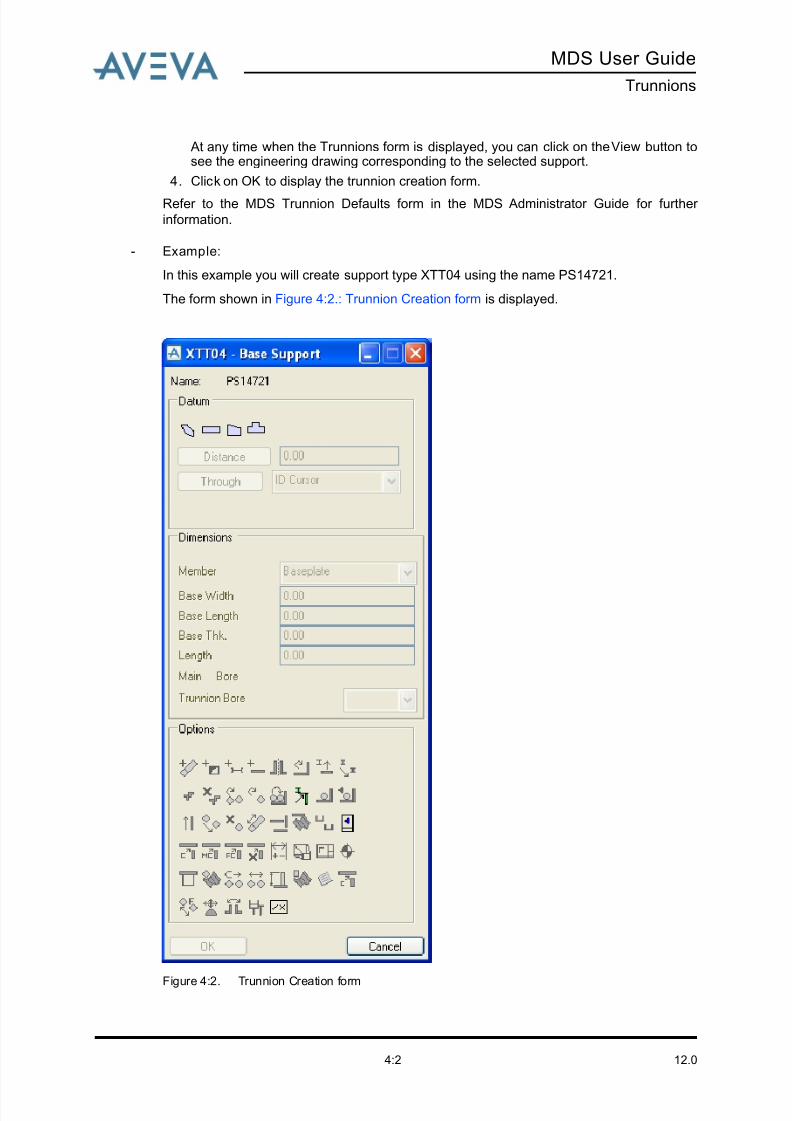
8/13/2019 Multi-Discipline Supports User Guide
http://slidepdf.com/reader/full/multi-discipline-supports-user-guide 66/125
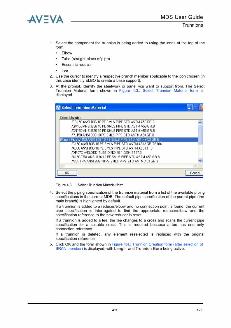
8/13/2019 Multi-Discipline Supports User Guide
http://slidepdf.com/reader/full/multi-discipline-supports-user-guide 67/125
MDS User Guide
Trunnions
12.04:3
1. Select the component the trunnion is being added to using the icons at the top of theform:
• Elbow
• Tube (straight piece of pipe)
• Eccentric reducer
• Tee
2. Use the cursor to identify a respective branch member applicable to the icon chosen (inthis case identify ELBO to create a base support).
3. At the prompt, identify the steelwork or panel you want to support from. The SelectTrunnion Material form shown in Figure 4:3.: Select Trunnion Material form isdisplayed.
Figure 4:3. Select Trunnion Material form
4. Select the piping specification of the trunnion material from a list of the available pipingspecifications in the current MDB. The default pipe specification of the parent pipe (themain branch) is highlighted by default.
If a trunnion is added to a reducer/elbow and no connection point is found, the currentpipe specification is interrogated to find the appropriate reducer/elbow and thespecification reference to the new reducer is reset.
If a trunnion is added to a tee, the tee changes to a cross and scans the current pipespecification for a suitable cross. This is required because a tee has one only
connection reference.If a trunnion is deleted, any element reselected is replaced with the originalspecification reference.
5. Click OK and the form shown in Figure 4:4.: Trunnion Creation form (after selection of BRAN member) is displayed, with Length and Trunnion Bore being active.
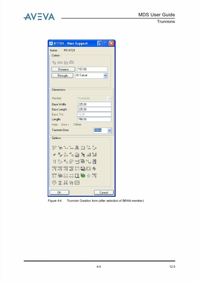
8/13/2019 Multi-Discipline Supports User Guide
http://slidepdf.com/reader/full/multi-discipline-supports-user-guide 68/125
12.04:4
MDS User Guide
Trunnions
Figure 4:4. Trunnion Creation form (after selection of BRAN member)

8/13/2019 Multi-Discipline Supports User Guide
http://slidepdf.com/reader/full/multi-discipline-supports-user-guide 69/125
MDS User Guide
Hangers
12.05:1
5 Hangers
The standard MDS application for hangers allows you to create fixed and variable pipe
hangers. The application is interactive and configurable, and simplifies:
• Definition of project related defaults.
• Control of hanger design.• Determination of range, types, and configuration of hanger components that can be
used on the project.
Hangers are designed using the hanger components catalogue of a given supplier and are
template-driven.
Note: The standard hanger templates are stored in a SITE named /MDS/HANGERS. To
use the standard hanger templates the default option property for the MDSHANGIF
keyword must be set to ‘Standard MDS’ on the PARAGON defaults database, (refer
to the MDS Admin Data form in the Administrator Guide).
The application is supplied with hanger templates from three different hanger component
suppliers. The project administrator can configure and customize those templates to adopt
any company’s hanger configurations or any other hanger components catalogue. For further information refer to the MDS Hanger Data form in the MDS Administrator Guide.
5.1 Creating a Hanger
There are two ways to access the hanger forms:
1. Click on the Fixed Hanger icon or Variable Hanger icon from the tool bar,
or …
2. Select the appropriate hanger from the Create drop-down menu (Figure 5:1.: Createmenu).

8/13/2019 Multi-Discipline Supports User Guide
http://slidepdf.com/reader/full/multi-discipline-supports-user-guide 70/125
12.05:2
MDS User Guide
Hangers
Figure 5:1. Create menu
3. Choose Fixed Hanger to display the form shown in Figure 5:2.: Fixed Hanger configurations form. This shows all the available hanger configurations that can becreated.
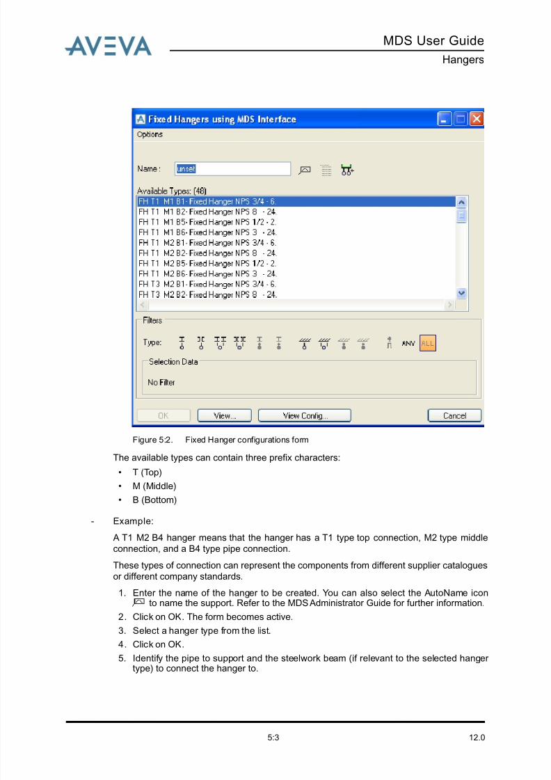
8/13/2019 Multi-Discipline Supports User Guide
http://slidepdf.com/reader/full/multi-discipline-supports-user-guide 71/125
MDS User Guide
Hangers
12.05:3
Figure 5:2. Fixed Hanger configurations form
The available types can contain three prefix characters:
• T (Top)
• M (Middle)
• B (Bottom)
- Example:
A T1 M2 B4 hanger means that the hanger has a T1 type top connection, M2 type middle
connection, and a B4 type pipe connection.
These types of connection can represent the components from different supplier catalogues
or different company standards.
1. Enter the name of the hanger to be created. You can also select the AutoName icon to name the support. Refer to the MDS Administrator Guide for further information.
2. Click on OK. The form becomes active.
3. Select a hanger type from the list.
4. Click on OK.
5. Identify the pipe to support and the steelwork beam (if relevant to the selected hanger type) to connect the hanger to.
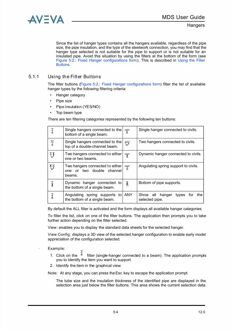
8/13/2019 Multi-Discipline Supports User Guide
http://slidepdf.com/reader/full/multi-discipline-supports-user-guide 72/125
12.05:4
MDS User Guide
Hangers
Since the list of hanger types contains all the hangers available, regardless of the pipesize, the pipe insulation, and the type of the steelwork connection, you may find that thehanger type selected is not suitable for the pipe to support or is not suitable for an
insulated pipe. Avoid this situation by using the filters at the bottom of the form (seeFigure 5:2.: Fixed Hanger configurations form). This is described in Using the Filter Buttons.
5.1.1 Using the Fi lter But tons
The filter buttons (Figure 5:2.: Fixed Hanger configurations form) filter the list of available
hanger types by the following filtering criteria:
• Hanger category
• Pipe size
• Pipe insulation (YES/NO)
• Top beam type
There are ten filtering categories represented by the following ten buttons:
By default the ALL filter is activated and the form displays all available hanger categories.
To filter the list, click on one of the filter buttons. The application then prompts you to take
further action depending on the filter selected.
View: enables you to display the standard data sheets for the selected hanger.
View Config: displays a 3D view of the selected hanger configuration to enable early model
appreciation of the configuration selected.
- Example:
1. Click on the filter (single-hanger connected to a beam). The application promptsyou to identify the item you want to support.
2. Identify the item in the graphical view.
Note: At any stage, you can press the Esc key to escape the application prompt.
The tube size and the insulation thickness of the identified pipe are displayed in theselection area just below the filter buttons. This area shows the current selection data.
Single hangers connected to the
bottom of a single beam.
Single hanger connected to civils.
Single hangers connected to the
top of a double-channel beam.
Two hangers connected to civils.
Two hangers connected to either
one or two beams.
Dynamic hanger connected to civils.
Two hangers connected to either
one or two double channel
beams.
Angulating spring support to civils.
Dynamic hanger connected to
the bottom of a single beam.
Bottom of pipe supports.
Angulating spring supports to
the bottom of a single beam.
ANY Show all hanger types for the
selected pipe.

8/13/2019 Multi-Discipline Supports User Guide
http://slidepdf.com/reader/full/multi-discipline-supports-user-guide 73/125
MDS User Guide
Hangers
12.05:5
The list displays the available hanger configurations for the selected category (single-hanger connected to a beam), pipe bore size, and insulation thickness.
The application prompts you to identify the steelwork beam you want to connect the
hanger to. The identified beam type is appended to the selection data in the formselection area.
In the case of double-hangers, or hangers connected to a double-channel beam, theapplication prompts you to identify the required additional beams.
The form displays a filtered list containing only the hanger configurations that meet theselection criteria (Figure 5:3.: Filtered Hanger configurations form).
Figure 5:3. Filtered Hanger configurations form
3. Enter the hanger name in the Name input field. You can also use the auto-naming
feature by clicking the AutoName icon .
4. Click OK.
5.2 Selecting a Creation Mode
The Hangers form (Figure 5:4.: Hanger Creation options) offers three modes to create
hangers.
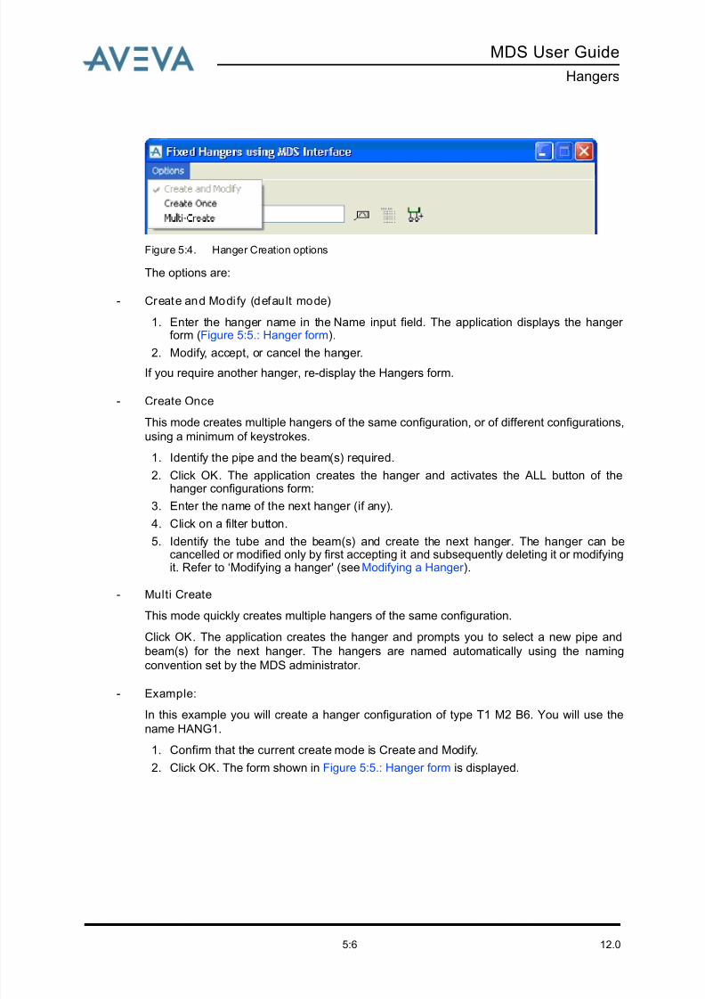
8/13/2019 Multi-Discipline Supports User Guide
http://slidepdf.com/reader/full/multi-discipline-supports-user-guide 74/125
12.05:6
MDS User Guide
Hangers
Figure 5:4. Hanger Creation options
The options are:
- Create and Modi fy (default mode)
1. Enter the hanger name in the Name input field. The application displays the hanger form (Figure 5:5.: Hanger form).
2. Modify, accept, or cancel the hanger.
If you require another hanger, re-display the Hangers form.
- Create Once
This mode creates multiple hangers of the same configuration, or of different configurations,
using a minimum of keystrokes.
1. Identify the pipe and the beam(s) required.
2. Click OK. The application creates the hanger and activates the ALL button of thehanger configurations form:
3. Enter the name of the next hanger (if any).
4. Click on a filter button.5. Identify the tube and the beam(s) and create the next hanger. The hanger can be
cancelled or modified only by first accepting it and subsequently deleting it or modifyingit. Refer to ‘Modifying a hanger' (see Modifying a Hanger ).
- Multi Create
This mode quickly creates multiple hangers of the same configuration.
Click OK. The application creates the hanger and prompts you to select a new pipe and
beam(s) for the next hanger. The hangers are named automatically using the naming
convention set by the MDS administrator.
- Example:
In this example you will create a hanger configuration of type T1 M2 B6. You will use the
name HANG1.
1. Confirm that the current create mode is Create and Modify.
2. Click OK. The form shown in Figure 5:5.: Hanger form is displayed.
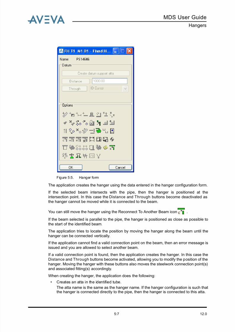
8/13/2019 Multi-Discipline Supports User Guide
http://slidepdf.com/reader/full/multi-discipline-supports-user-guide 75/125
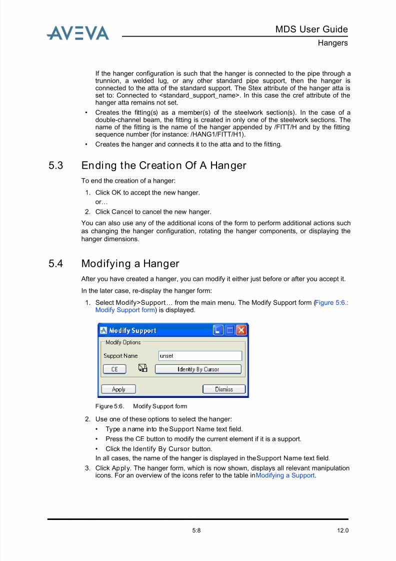
8/13/2019 Multi-Discipline Supports User Guide
http://slidepdf.com/reader/full/multi-discipline-supports-user-guide 76/125
12.05:8
MDS User Guide
Hangers
If the hanger configuration is such that the hanger is connected to the pipe through atrunnion, a welded lug, or any other standard pipe support, then the hanger isconnected to the atta of the standard support. The Stex attribute of the hanger atta is
set to: Connected to <standard_support_name>. In this case the cref attribute of thehanger atta remains not set.
• Creates the fitting(s) as a member(s) of the steelwork section(s). In the case of adouble-channel beam, the fitting is created in only one of the steelwork sections. Thename of the fitting is the name of the hanger appended by /FITT/H and by the fittingsequence number (for instance: /HANG1/FITT/H1).
• Creates the hanger and connects it to the atta and to the fitting.
5.3 Ending the Creat ion Of A Hanger
To end the creation of a hanger:
1. Click OK to accept the new hanger.
or …
2. Click Cancel to cancel the new hanger.
You can also use any of the additional icons of the form to perform additional actions such
as changing the hanger configuration, rotating the hanger components, or displaying the
hanger dimensions.
5.4 Modifying a Hanger
After you have created a hanger, you can modify it either just before or after you accept it.
In the later case, re-display the hanger form:
1. Select Modify>Support… from the main menu. The Modify Support form (Figure 5:6.:Modify Support form) is displayed.
Figure 5:6. Modify Support form
2. Use one of these options to select the hanger:
• Type a name into the Support Name text field.
• Press the CE button to modify the current element if it is a support.
• Click the Identify By Cursor button.
In all cases, the name of the hanger is displayed in the Support Name text field.
3. Click Apply. The hanger form, which is now shown, displays all relevant manipulationicons. For an overview of the icons refer to the table in Modifying a Support.
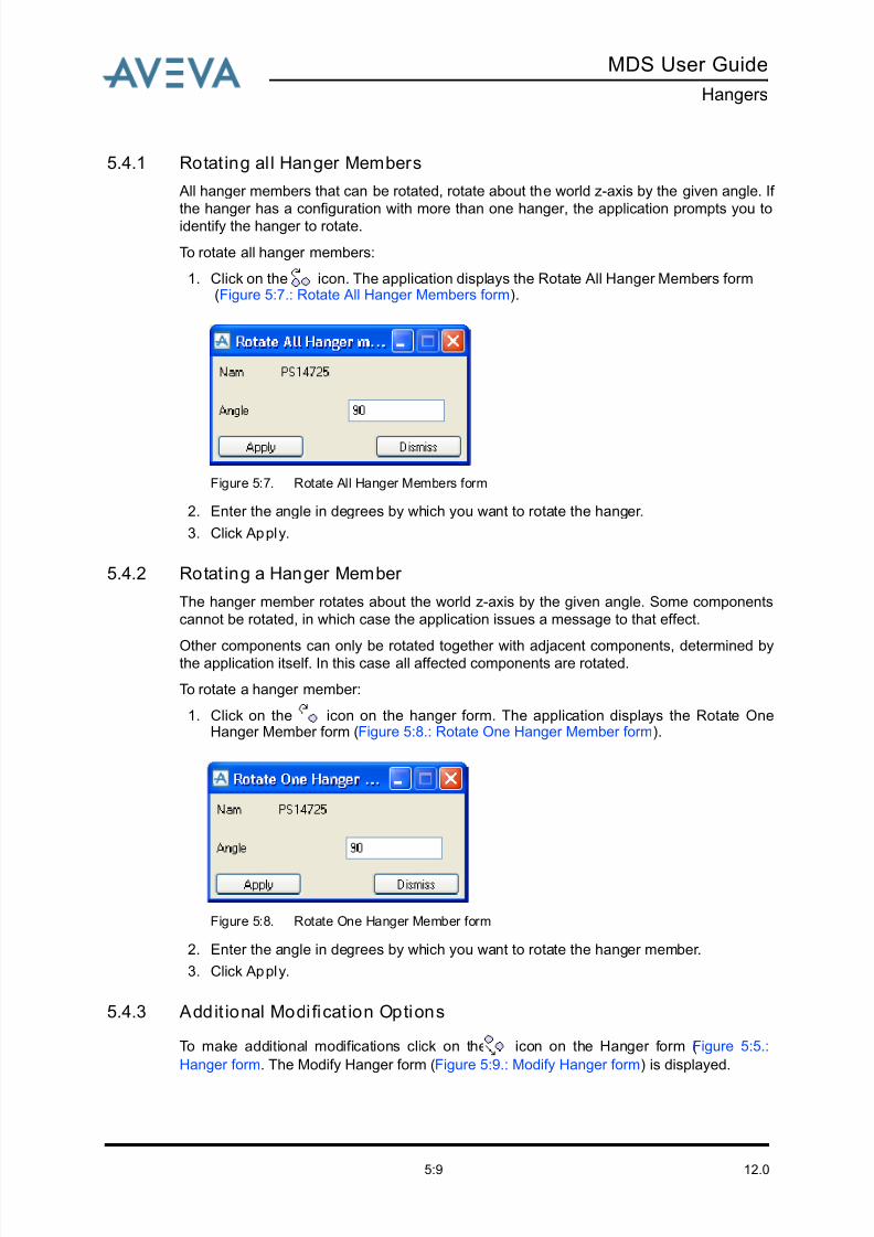
8/13/2019 Multi-Discipline Supports User Guide
http://slidepdf.com/reader/full/multi-discipline-supports-user-guide 77/125
MDS User Guide
Hangers
12.05:9
5.4.1 Rotating all Hanger Members
All hanger members that can be rotated, rotate about the world z-axis by the given angle. If
the hanger has a configuration with more than one hanger, the application prompts you to
identify the hanger to rotate.
To rotate all hanger members:
1. Click on the icon. The application displays the Rotate All Hanger Members form (Figure 5:7.: Rotate All Hanger Members form).
Figure 5:7. Rotate All Hanger Members form
2. Enter the angle in degrees by which you want to rotate the hanger.
3. Click Apply.
5.4.2 Rotat ing a Hanger Member
The hanger member rotates about the world z-axis by the given angle. Some components
cannot be rotated, in which case the application issues a message to that effect.
Other components can only be rotated together with adjacent components, determined bythe application itself. In this case all affected components are rotated.
To rotate a hanger member:
1. Click on the icon on the hanger form. The application displays the Rotate OneHanger Member form (Figure 5:8.: Rotate One Hanger Member form).
Figure 5:8. Rotate One Hanger Member form
2. Enter the angle in degrees by which you want to rotate the hanger member.
3. Click Apply.
5.4.3 Addit ional Modificat ion Options
To make additional modifications click on the icon on the Hanger form (Figure 5:5.:
Hanger form. The Modify Hanger form (Figure 5:9.: Modify Hanger form) is displayed.
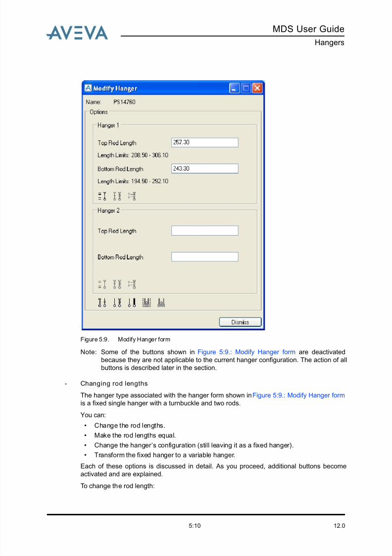
8/13/2019 Multi-Discipline Supports User Guide
http://slidepdf.com/reader/full/multi-discipline-supports-user-guide 78/125
12.05:10
MDS User Guide
Hangers
Figure 5:9. Modify Hanger form
Note: Some of the buttons shown in Figure 5:9.: Modify Hanger form are deactivated
because they are not applicable to the current hanger configuration. The action of all
buttons is described later in the section.
- Changing rod lengths
The hanger type associated with the hanger form shown in Figure 5:9.: Modify Hanger form
is a fixed single hanger with a turnbuckle and two rods.
You can:
• Change the rod lengths.
• Make the rod lengths equal.
• Change the hanger’s configuration (still leaving it as a fixed hanger).
• Transform the fixed hanger to a variable hanger.
Each of these options is discussed in detail. As you proceed, additional buttons become
activated and are explained.
To change the rod length:

8/13/2019 Multi-Discipline Supports User Guide
http://slidepdf.com/reader/full/multi-discipline-supports-user-guide 79/125
MDS User Guide
Hangers
12.05:11
• Enter the required length in the appropriate input field. The rod length is modifiedaccordingly.
Each rod has a minimum and maximum allowed length. These values depend on the limits
set by the MDS Administrator. Refer to the MDS Administrator Guide for more information.
Changing the length of one rod automatically updates the length of the other rod, such that
the total hanger height does not change.
To make the rods lengths equal:
• Click on the icon.
- Modi fy ing the hanger configurat ion
You can change the hanger configuration with the following restrictions:
• The new and existing configurations must have the same basic connection types. Aconfiguration in which the hanger is connected to the pipe using a pipe clamp can have
its configuration changed to a similar configuration with a different type of pipe clamp.However this configuration cannot be changed to a hanger with a connection to a pipelug or an elbow trunnion. The converse situations are also true.
• If the type of connection to the steelwork of the new configuration is different from thatof the existing configuration, the application prompts you to identify the steelworksection(s) accordingly.
To modify the hanger configuration:
1. Click on the icon. The fixed hanger configurations form opens with the appropriatefilter is activated. In this case it is the first filter ( ).
2. Select a new configuration from the displayed filtered list, or click on another filter button and select another type of configuration.
3. For the purpose of this particular explanation, select the T3 M2 B6 configuration fromthe filtered list.
The activated filter is not being changed. The application therefore tries to replace thecurrent hanger configuration with the new configuration based on the current pipe andbeam connections.
If the new configuration has a different beam connection (for instance a double channelconnection two beam connection for a double hanger), then the application promptsyou to identify the beam(s) for the new connection type.
4. Click on the T3 M2 B6 hanger configuration.
5. Click OK. The fixed hanger configurations form closes and the hanger form is re-displayed.
Note: The title of the form changes to reflect the new configuration.
6. Click on the icon. The Modify Hanger form is displayed.
The rod lengths are deactivated and cannot be changed because the T3 M2 B6configuration has a fixed length welded eye rod. The bottom rod length cannot bechanged either because to do so would change the total height of the hanger.
- Changing the hanger type from Fixed to Variable
To change the hanger type from Fixed to Variable:
1. Click on the icon. The hangers configuration form is displayed. The form lists onlyvariable hanger configurations. The active filter is the single-hanger filter ( ) becausethis is a single-hanger and the application assumes that in most cases you will modify
the configuration within the same hanger category. You can change the category by
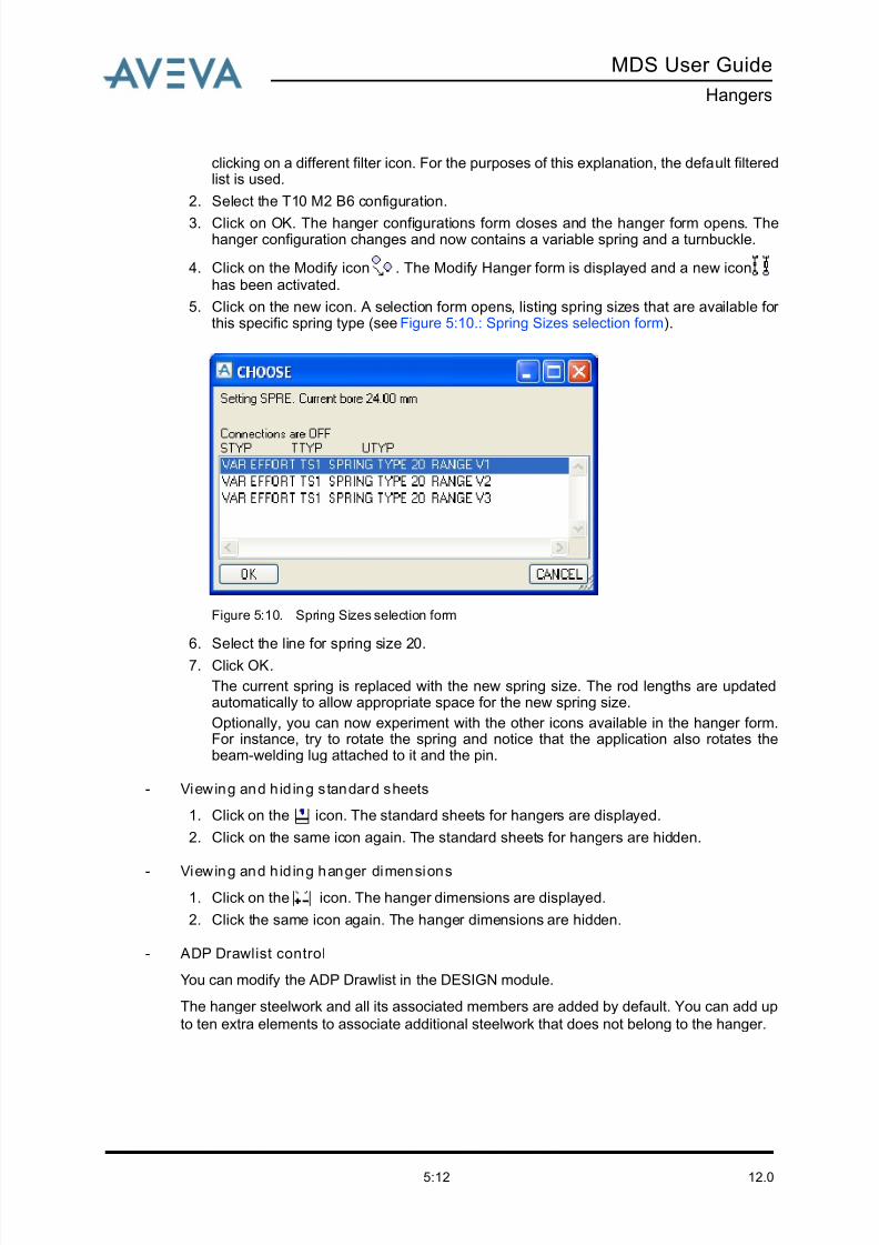
8/13/2019 Multi-Discipline Supports User Guide
http://slidepdf.com/reader/full/multi-discipline-supports-user-guide 80/125
12.05:12
MDS User Guide
Hangers
clicking on a different filter icon. For the purposes of this explanation, the default filteredlist is used.
2. Select the T10 M2 B6 configuration.
3. Click on OK. The hanger configurations form closes and the hanger form opens. Thehanger configuration changes and now contains a variable spring and a turnbuckle.
4. Click on the Modify icon . The Modify Hanger form is displayed and a new iconhas been activated.
5. Click on the new icon. A selection form opens, listing spring sizes that are available for this specific spring type (see Figure 5:10.: Spring Sizes selection form).
Figure 5:10. Spring Sizes selection form
6. Select the line for spring size 20.
7. Click OK.
The current spring is replaced with the new spring size. The rod lengths are updatedautomatically to allow appropriate space for the new spring size.
Optionally, you can now experiment with the other icons available in the hanger form.For instance, try to rotate the spring and notice that the application also rotates thebeam-welding lug attached to it and the pin.
- Viewing and h id ing s tandard sheets
1. Click on the icon. The standard sheets for hangers are displayed.
2. Click on the same icon again. The standard sheets for hangers are hidden.
- Viewing and h id ing hanger dimensions
1. Click on the icon. The hanger dimensions are displayed.
2. Click the same icon again. The hanger dimensions are hidden.
- ADP Drawlist control
You can modify the ADP Drawlist in the DESIGN module.
The hanger steelwork and all its associated members are added by default. You can add up
to ten extra elements to associate additional steelwork that does not belong to the hanger.
8/13/2019 Multi-Discipline Supports User Guide
http://slidepdf.com/reader/full/multi-discipline-supports-user-guide 81/125
MDS User Guide
Hangers
12.05:13
- Centre on hanger
Click on the icon. The graphical view of the support being created or modified is
refreshed. The view scale is not modified.
- Re-connecting a hanger to a new steelwork beam
Click on the icon. The hanger is connected to a new steelwork beam.
If necessary, the application moves the hanger to a new position, in order to satisfy the new
connection point. The old fitting is deleted and a new fitting is created below the new
steelwork section.
If necessary, and if the hanger contains rods, they are adjusted to maintain the correct
hanger height.
If the new connection is not valid (for instance, the hanger is not vertical because the rods
are too long or too short), an error message is displayed and the application restores theoriginal hanger state.
- Adding a note
Click on the icon. You can now add a note to be displayed on the hanger drawing.
- Quick reference notes about modifying hangers
• For a steelwork section that is parallel to the pipe, use the Distance or Throughbuttons. This is not considered as a reconnection action since the fitting only moves tothe new position. It is not replaced with a new fitting.
• For double-hangers, there is one connection for each hanger. The application prompts
twice for the two beams. If only one connection needs to be modified, then for theconnection that you do not want to modify, identify the first beam again. The hanger isre-connected to the same beam.
• For hangers that are connected to a double-channel beam, the application prompttwice to identify each of the channels. A check is made that the two identified channelsections form a valid double-channel beam (that is: the same top level, facing eachother back to back).
5.5 Creating an MDS Hanger using a Manufacturer’s
Interface
There are three MDS Hanger manufacturer interfaces available for use with the MDSapplication.
1. The MDS Witch Hanger interface, which uses the Carpenter & Paterson Ltd. WitchHanger design software.
2. The MDS PSDesigner hanger interface, which uses the Pipe Supports Ltd.PSDesigner hanger design software.
3. The MDS LICAD hanger interface, which uses the Lisega LICAD hanger designsoftware.
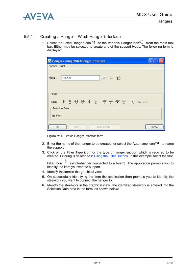
8/13/2019 Multi-Discipline Supports User Guide
http://slidepdf.com/reader/full/multi-discipline-supports-user-guide 82/125
12.05:14
MDS User Guide
Hangers
5.5.1 Creating a Hanger - Witch Hanger interface
1. Select the Fixed Hanger icon or the Variable Hanger icon from the main toolbar. Either may be selected to create any of the support types. The following form isdisplayed:
Figure 5:11. Witch Hanger Interface form
2. Enter the name of the hanger to be created, or select the Autoname icon to namethe support.
3. Click on the Filter Type icon for the type of hanger support which is required to becreated. Filtering is described in Using the Filter Buttons. In this example select the first
Filter Icon (single-hanger connected to a beam). The application prompts you toidentify the item you want to support.
4. Identify the item in the graphical view.
5. On successfully identifying the item the application then prompts you to identify thesteelwork you want to connect the hanger to.
6. Identify the steelwork in the graphical view. The identified steelwork is entered into theSelection Data area in the form, as shown below:
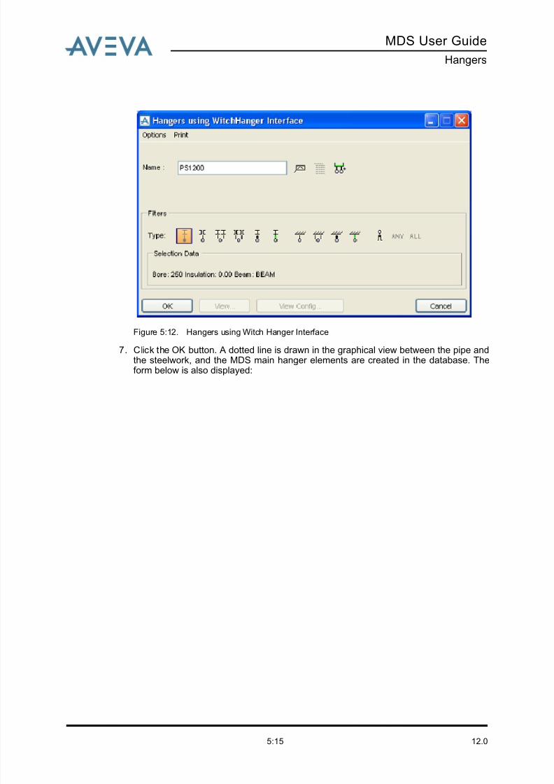
8/13/2019 Multi-Discipline Supports User Guide
http://slidepdf.com/reader/full/multi-discipline-supports-user-guide 83/125
MDS User Guide
Hangers
12.05:15
Figure 5:12. Hangers using Witch Hanger Interface
7. Click the OK button. A dotted line is drawn in the graphical view between the pipe andthe steelwork, and the MDS main hanger elements are created in the database. Theform below is also displayed:
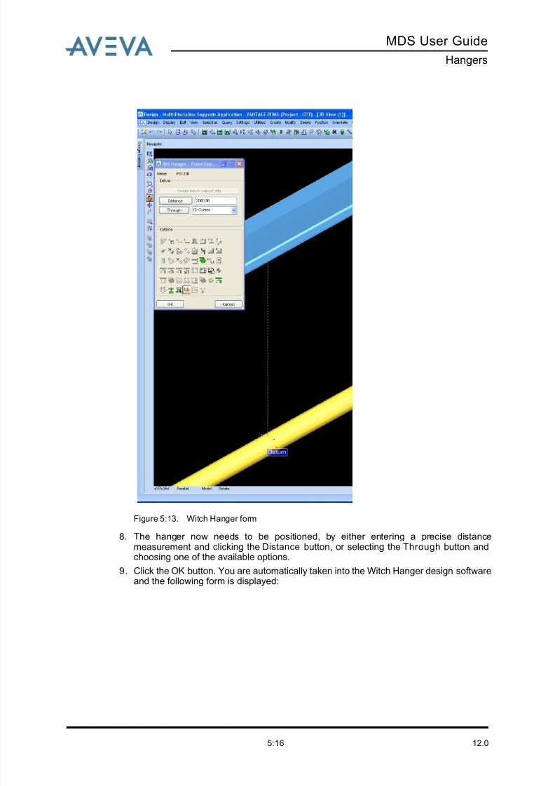
8/13/2019 Multi-Discipline Supports User Guide
http://slidepdf.com/reader/full/multi-discipline-supports-user-guide 84/125
12.05:16
MDS User Guide
Hangers
Figure 5:13. Witch Hanger form
8. The hanger now needs to be positioned, by either entering a precise distance
measurement and clicking the Distance button, or selecting the Through button andchoosing one of the available options.
9. Click the OK button. You are automatically taken into the Witch Hanger design softwareand the following form is displayed:
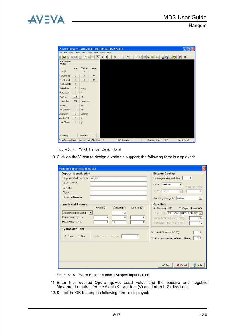
8/13/2019 Multi-Discipline Supports User Guide
http://slidepdf.com/reader/full/multi-discipline-supports-user-guide 85/125
MDS User Guide
Hangers
12.05:17
Figure 5:14. Witch Hanger Design form
10. Click on the V icon to design a variable support; the following form is displayed:
Figure 5:15. Witch Hanger Variable Support Input Screen
11. Enter the required Operating/Hot Load value and the positive and negativeMovement required for the Ax ial (X), Verti cal (V) and Lateral (Z) directions.
12. Select the OK button; the following form is displayed:
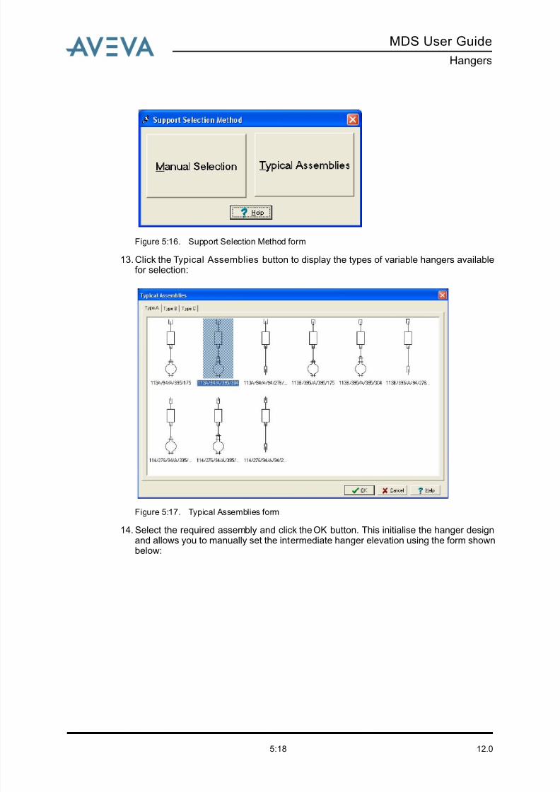
8/13/2019 Multi-Discipline Supports User Guide
http://slidepdf.com/reader/full/multi-discipline-supports-user-guide 86/125
12.05:18
MDS User Guide
Hangers
Figure 5:16. Support Selection Method form
13. Click the Typical Assemblies button to display the types of variable hangers availablefor selection:
Figure 5:17. Typical Assemblies form
14. Select the required assembly and click the OK button. This initialise the hanger designand allows you to manually set the intermediate hanger elevation using the form shown
below:
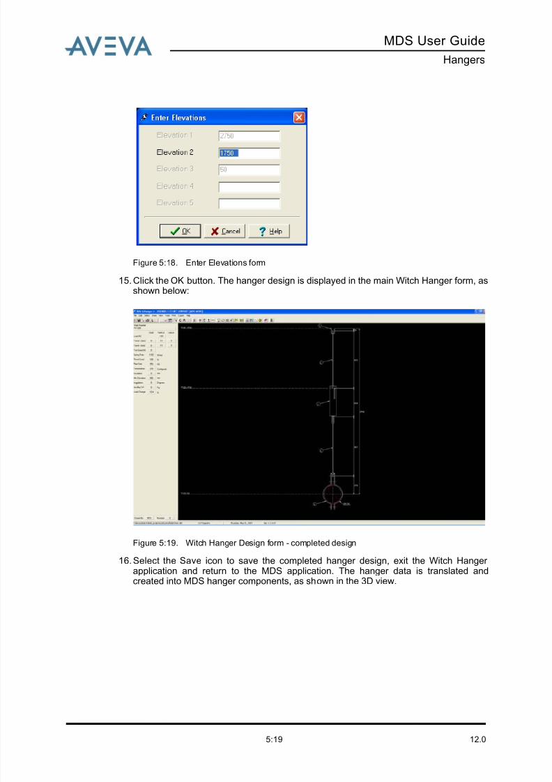
8/13/2019 Multi-Discipline Supports User Guide
http://slidepdf.com/reader/full/multi-discipline-supports-user-guide 87/125
MDS User Guide
Hangers
12.05:19
Figure 5:18. Enter Elevations form
15. Click the OK button. The hanger design is displayed in the main Witch Hanger form, asshown below:
Figure 5:19. Witch Hanger Design form - completed design
16. Select the Save icon to save the completed hanger design, exit the Witch Hanger application and return to the MDS application. The hanger data is translated andcreated into MDS hanger components, as shown in the 3D view.
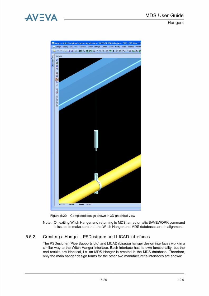
8/13/2019 Multi-Discipline Supports User Guide
http://slidepdf.com/reader/full/multi-discipline-supports-user-guide 88/125
12.05:20
MDS User Guide
Hangers
Figure 5:20. Completed design shown in 3D graphical view
Note: On exiting Witch Hanger and returning to MDS, an automatic SAVEWORK command
is issued to make sure that the Witch Hanger and MDS databases are in alignment.
5.5.2 Creating a Hanger - PSDesigner and LICAD Interfaces
The PSDesigner (Pipe Supports Ltd) and LICAD (Lisega) hanger design interfaces work in a
similar way to the Witch Hanger interface. Each interface has its own functionality, but the
end results are identical, i.e. an MDS Hanger is created in the MDS database. Therefore,
only the main hanger design forms for the other two manufacturer’s interfaces are shown:
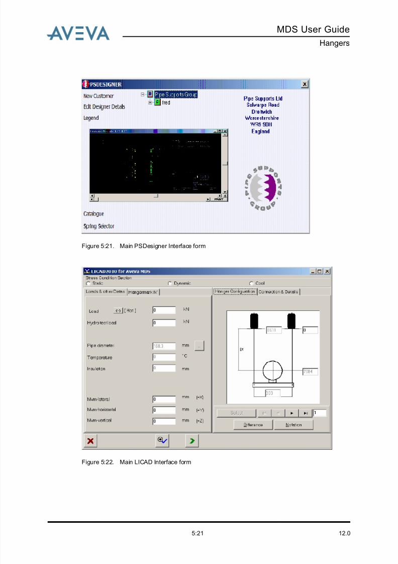
8/13/2019 Multi-Discipline Supports User Guide
http://slidepdf.com/reader/full/multi-discipline-supports-user-guide 89/125
MDS User Guide
Hangers
12.05:21
Figure 5:21. Main PSDesigner Interface form
Figure 5:22. Main LICAD Interface form

8/13/2019 Multi-Discipline Supports User Guide
http://slidepdf.com/reader/full/multi-discipline-supports-user-guide 90/125
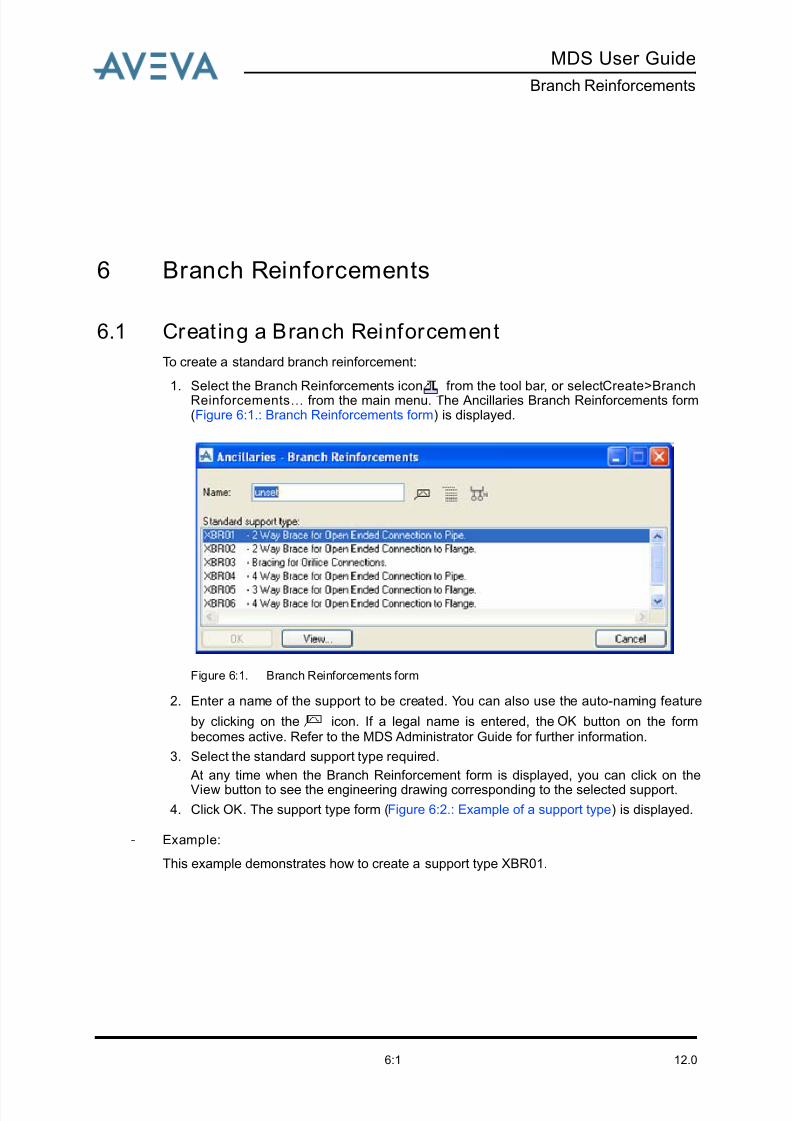
8/13/2019 Multi-Discipline Supports User Guide
http://slidepdf.com/reader/full/multi-discipline-supports-user-guide 91/125
MDS User Guide
Branch Reinforcements
12.06:1
6 Branch Reinforcements
6.1 Creating a Branch Reinforcement
To create a standard branch reinforcement:
1. Select the Branch Reinforcements icon from the tool bar, or select Create>BranchReinforcements…
from the main menu. The Ancillaries Branch Reinforcements form(Figure 6:1.: Branch Reinforcements form) is displayed.
Figure 6:1. Branch Reinforcements form
2. Enter a name of the support to be created. You can also use the auto-naming feature
by clicking on the icon. If a legal name is entered, the OK button on the formbecomes active. Refer to the MDS Administrator Guide for further information.
3. Select the standard support type required.
At any time when the Branch Reinforcement form is displayed, you can click on the
View button to see the engineering drawing corresponding to the selected support.
4. Click OK. The support type form (Figure 6:2.: Example of a support type) is displayed.
- Example:
This example demonstrates how to create a support type XBR01.
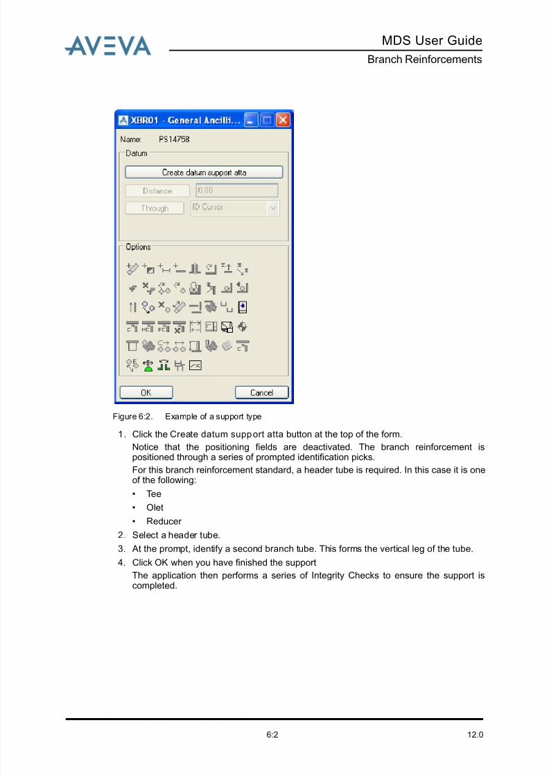
8/13/2019 Multi-Discipline Supports User Guide
http://slidepdf.com/reader/full/multi-discipline-supports-user-guide 92/125
12.06:2
MDS User Guide
Branch Reinforcements
Figure 6:2. Example of a support type
1. Click the Create datum support atta button at the top of the form.
Notice that the positioning fields are deactivated. The branch reinforcement ispositioned through a series of prompted identification picks.
For this branch reinforcement standard, a header tube is required. In this case it is oneof the following:
• Tee
• Olet
• Reducer
2. Select a header tube.
3. At the prompt, identify a second branch tube. This forms the vertical leg of the tube.
4. Click OK when you have finished the support
The application then performs a series of Integrity Checks to ensure the support iscompleted.
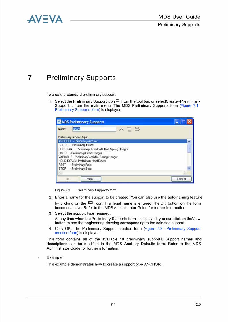
8/13/2019 Multi-Discipline Supports User Guide
http://slidepdf.com/reader/full/multi-discipline-supports-user-guide 93/125
MDS User Guide
Preliminary Supports
12.07:1
7 Preliminary Supports
To create a standard preliminary support:
1. Select the Preliminary Support icon from the tool bar, or select Create>PreliminarySupport... from the main menu. The MDS Preliminary Supports form (Figure 7:1.:Preliminary Supports form) is displayed.
Figure 7:1. Preliminary Supports form
2. Enter a name for the support to be created. You can also use the auto-naming feature
by clicking on the icon. If a legal name is entered, the OK button on the formbecomes active. Refer to the MDS Administrator Guide for further information.
3. Select the support type required.
At any time when the Preliminary Supports form is displayed, you can click on the Viewbutton to see the engineering drawing corresponding to the selected support.
4. Click OK. The Preliminary Support creation form (Figure 7:2.: Preliminary Supportcreation form) is displayed.
This form contains all of the available 18 preliminary supports. Support names and
descriptions can be modified in the MDS Ancillary Defaults form. Refer to the MDS
Administrator Guide for further information.
- Example:
This example demonstrates how to create a support type ANCHOR.
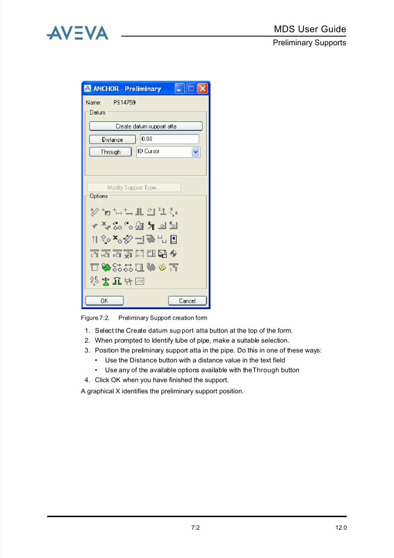
8/13/2019 Multi-Discipline Supports User Guide
http://slidepdf.com/reader/full/multi-discipline-supports-user-guide 94/125
12.07:2
MDS User Guide
Preliminary Supports
Figure 7:2. Preliminary Support creation form
1. Select the Create datum support atta button at the top of the form.
2. When prompted to Identify tube of pipe, make a suitable selection.
3. Position the preliminary support atta in the pipe. Do this in one of these ways:
• Use the Distance button with a distance value in the text field
• Use any of the available options available with the Through button
4. Click OK when you have finished the support.
A graphical X identifies the preliminary support position.
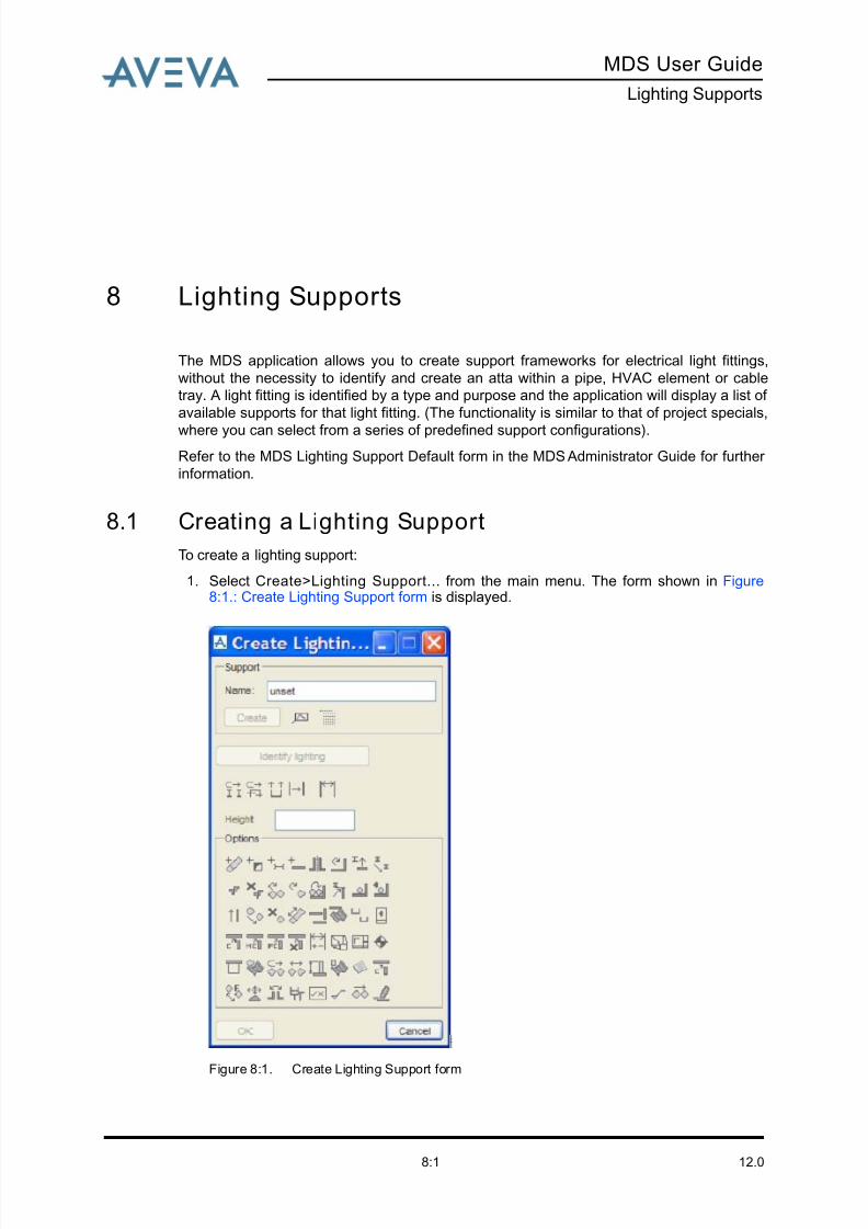
8/13/2019 Multi-Discipline Supports User Guide
http://slidepdf.com/reader/full/multi-discipline-supports-user-guide 95/125
MDS User Guide
Lighting Supports
12.08:1
8 Lighting Supports
The MDS application allows you to create support frameworks for electrical light fittings,
without the necessity to identify and create an atta within a pipe, HVAC element or cable
tray. A light fitting is identified by a type and purpose and the application will display a list of
available supports for that light fitting. (The functionality is similar to that of project specials,
where you can select from a series of predefined support configurations).
Refer to the MDS Lighting Support Default form in the MDS Administrator Guide for further
information.
8.1 Creating a Lighting Support
To create a lighting support:
1. Select Create>Lighting Support... from the main menu. The form shown in Figure8:1.: Create Lighting Support form is displayed.
Figure 8:1. Create Lighting Support form
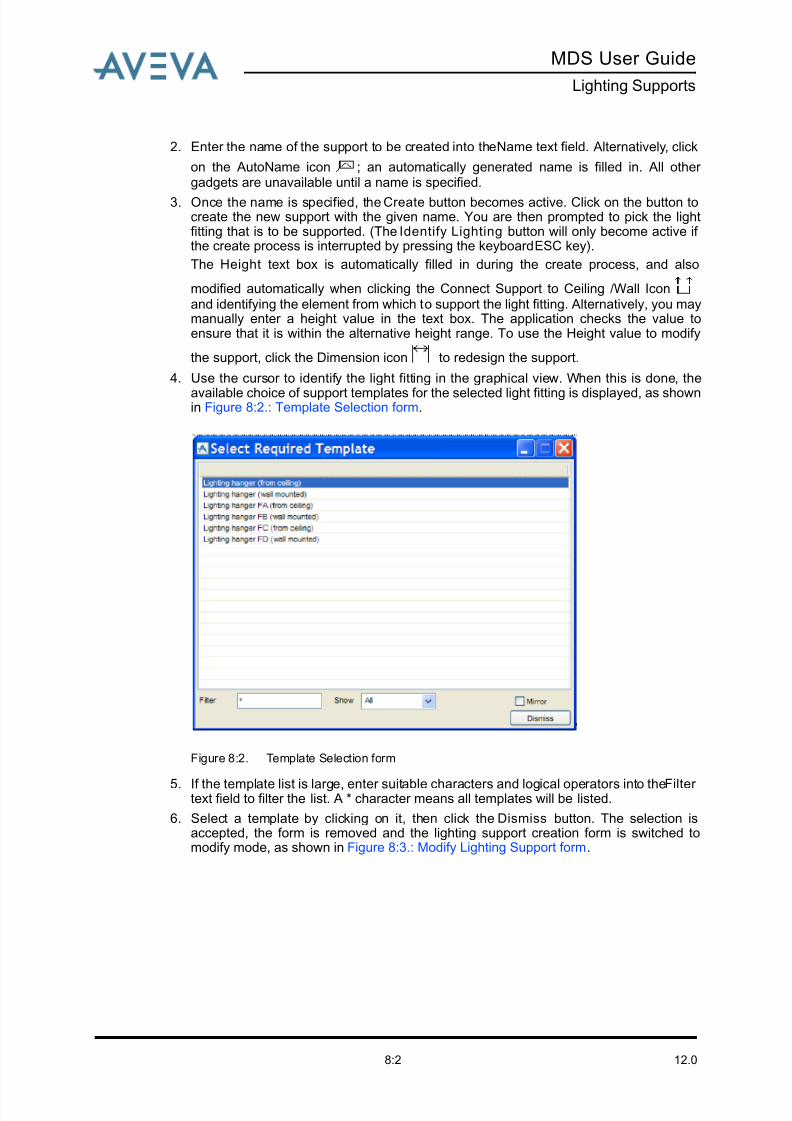
8/13/2019 Multi-Discipline Supports User Guide
http://slidepdf.com/reader/full/multi-discipline-supports-user-guide 96/125
12.08:2
MDS User Guide
Lighting Supports
2. Enter the name of the support to be created into the Name text field. Alternatively, click
on the AutoName icon ; an automatically generated name is filled in. All other gadgets are unavailable until a name is specified.
3. Once the name is specified, the Create button becomes active. Click on the button tocreate the new support with the given name. You are then prompted to pick the lightfitting that is to be supported. (The Identify Lighting button will only become active if the create process is interrupted by pressing the keyboard ESC key).
The Height text box is automatically filled in during the create process, and also
modified automatically when clicking the Connect Support to Ceiling /Wall Iconand identifying the element from which to support the light fitting. Alternatively, you maymanually enter a height value in the text box. The application checks the value toensure that it is within the alternative height range. To use the Height value to modify
the support, click the Dimension icon to redesign the support.
4. Use the cursor to identify the light fitting in the graphical view. When this is done, the
available choice of support templates for the selected light fitting is displayed, as shownin Figure 8:2.: Template Selection form.
Figure 8:2. Template Selection form
5. If the template list is large, enter suitable characters and logical operators into the Filter text field to filter the list. A * character means all templates will be listed.
6. Select a template by clicking on it, then click the Dismiss button. The selection isaccepted, the form is removed and the lighting support creation form is switched tomodify mode, as shown in Figure 8:3.: Modify Lighting Support form.

8/13/2019 Multi-Discipline Supports User Guide
http://slidepdf.com/reader/full/multi-discipline-supports-user-guide 97/125
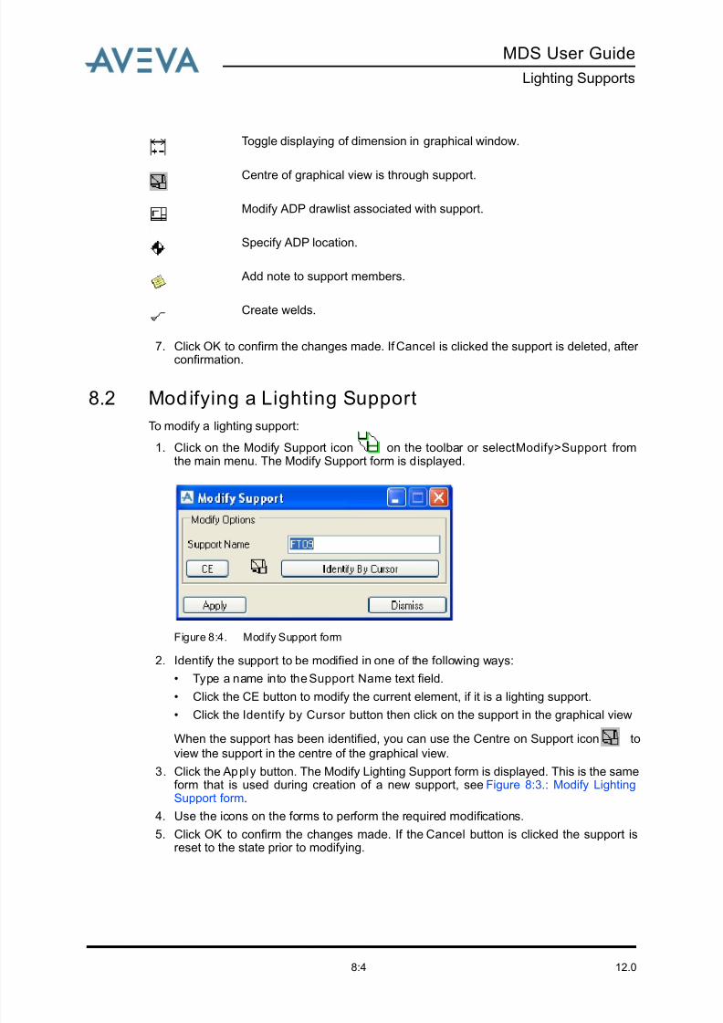
8/13/2019 Multi-Discipline Supports User Guide
http://slidepdf.com/reader/full/multi-discipline-supports-user-guide 98/125

8/13/2019 Multi-Discipline Supports User Guide
http://slidepdf.com/reader/full/multi-discipline-supports-user-guide 99/125
MDS User Guide
Welding Application
12.09:1
9 Welding Application
The Weld application provides welds for:
• Ancillaries (for example u-bolts and clips)
• Sections
• JointsWelds for ancillaries and joints are created in the MDS catalogue project by the project
administrator. Most of the framework welds for sections and joints are also created in this
way. However, some welds are not part of the template and must be created by you during
support creation.
The creation/modification/deletion of welds is explained in the following sections.
9.1 Creating a Weld on a Framework or Special
To create a weld:
• Select the Create Weld icon from the MDS Framework or Special Framework form.The Framework Weld Selection form (Figure 9:1.: Framework Weld Selection form) isdisplayed.

8/13/2019 Multi-Discipline Supports User Guide
http://slidepdf.com/reader/full/multi-discipline-supports-user-guide 100/125
12.09:2
MDS User Guide
Welding Application
Figure 9:1. Framework Weld Selection form
All Welds created or modified are stored in a TMPL at the STRU level of the support in your
database. They are displayed together with all relevant welding information in the weld list,
such as shown below.
1. Click on New Weld. The Select Standard Weld form (Figure 9:2.: Select Standard Weldform) is displayed.
Section: The name of the section with which the Weld is associated.
Weld name: The name of the weld as stored in the TMPL in your database.
Symbol Name: The name of the symbol as used in DRAFT on the MDS
drawing.
Description: Text to describe the weld type.
Weld Size: The size of the weld that is output on the MDS drawing.
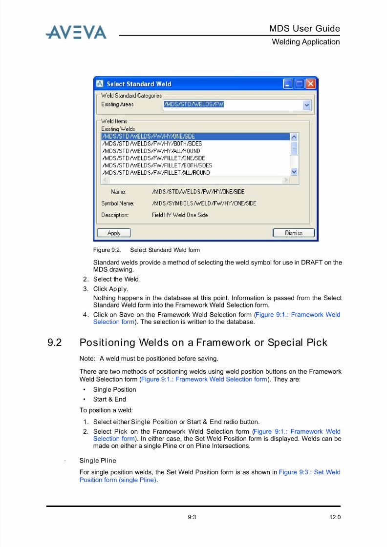
8/13/2019 Multi-Discipline Supports User Guide
http://slidepdf.com/reader/full/multi-discipline-supports-user-guide 101/125
MDS User Guide
Welding Application
12.09:3
Figure 9:2. Select Standard Weld form
Standard welds provide a method of selecting the weld symbol for use in DRAFT on theMDS drawing.
2. Select the Weld.
3. Click Apply.
Nothing happens in the database at this point. Information is passed from the SelectStandard Weld form into the Framework Weld Selection form.
4. Click on Save on the Framework Weld Selection form (Figure 9:1.: Framework WeldSelection form). The selection is written to the database.
9.2 Positioning Welds on a Framework or Special Pick
Note: A weld must be positioned before saving.
There are two methods of positioning welds using weld position buttons on the Framework
Weld Selection form (Figure 9:1.: Framework Weld Selection form). They are:
• Single Position
• Start & End
To position a weld:
1. Select either Single Position or Start & End radio button.
2. Select Pick on the Framework Weld Selection form (Figure 9:1.: Framework WeldSelection form). In either case, the Set Weld Position form is displayed. Welds can bemade on either a single Pline or on Pline Intersections.
- Single Pline
For single position welds, the Set Weld Position form is as shown in Figure 9:3.: Set Weld
Position form (single Pline).
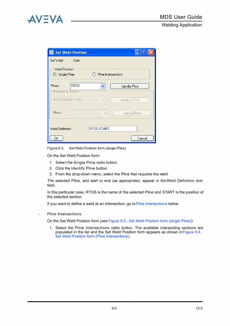
8/13/2019 Multi-Discipline Supports User Guide
http://slidepdf.com/reader/full/multi-discipline-supports-user-guide 102/125
12.09:4
MDS User Guide
Welding Application
Figure 9:3. Set Weld Position form (single Pline)
On the Set Weld Position form:
1. Select the Single Pline radio button.
2. Click the Identify Pline button.
3. From the drop-down menu, select the Pline that requires the weld.
The selected Pline, and start or end (as appropriate), appear in the Weld Definition text
field.
In this particular case, RTOS is the name of the selected Pline and START is the position of
the selected section.
If you want to define a weld at an intersection, go to Pline Intersections below.
- Pline Intersections
On the Set Weld Position form (see Figure 9:3.: Set Weld Position form (single Pline)):
1. Select the Pline Intersections radio button. The available intersecting sections arepopulated in the list and the Set Weld Position form appears as shown in Figure 9:4.:Set Weld Position form (Pline Intersections).
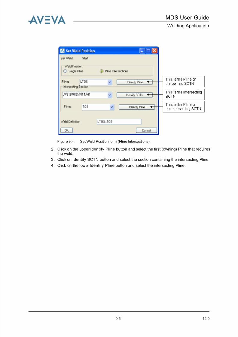
8/13/2019 Multi-Discipline Supports User Guide
http://slidepdf.com/reader/full/multi-discipline-supports-user-guide 103/125
MDS User Guide
Welding Application
12.09:5
Figure 9:4. Set Weld Position form (Pline Intersections)
2. Click on the upper Identify Pline button and select the first (owning) Pline that requiresthe weld.
3. Click on Identify SCTN button and select the section containing the intersecting Pline.
4. Click on the lower Identify Pline button and select the intersecting Pline.

8/13/2019 Multi-Discipline Supports User Guide
http://slidepdf.com/reader/full/multi-discipline-supports-user-guide 104/125
12.09:6
MDS User Guide
Welding Application
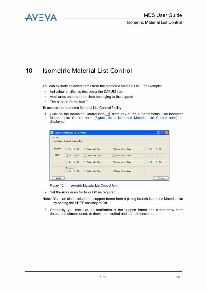
8/13/2019 Multi-Discipline Supports User Guide
http://slidepdf.com/reader/full/multi-discipline-supports-user-guide 105/125
MDS User Guide
Isometric Material List Control
12.010:1
10 Isometric Material List Control
You can exclude selected items from the Isometric Material List. For example:
• Individual ancillaries (including the DATUM atta)
• Ancillaries on other branches belonging to the support
• The support frame itself To access the Isometric Material List Control facility:
1. Click on the Isometric Control icon from any of the support forms. The IsometricMaterial List Control form (Figure 10:1.: Isometric Material List Control form) isdisplayed.
Figure 10:1. Isometric Material List Control form
2. Set the Ancillaries to On or Off as required.
Note: You can also exclude the support frame from a piping branch Isometric Material List
by setting the SREF ancillary to Off .
3. Optionally, you can exclude ancillaries or the support frame and either draw themdotted and dimensioned, or draw them dotted and non-dimensioned.

8/13/2019 Multi-Discipline Supports User Guide
http://slidepdf.com/reader/full/multi-discipline-supports-user-guide 106/125
12.010:2
MDS User Guide
Isometric Material List Control
8/13/2019 Multi-Discipline Supports User Guide
http://slidepdf.com/reader/full/multi-discipline-supports-user-guide 107/125
MDS User Guide
Data Access Control
12.011:1
11 Data Access Control
The teams owning the database mechanisms handle the method of controlling data access.
In addition, the following access control features allow you to specify in additional detail
what operations a user can carry out on elements in the database. This is known as Data
Access Control (DAC).
Note: To use DAC it must be switched on for the project, otherwise only the teams owning
database controls will apply.
With DAC switched on, all general users are prevented from carrying out any operation on
any part of the database unless they have specifically been given the necessary access
rights. DAC uses the following new administration database elements:
• Role defines the type of operations a user can carry out. For example, creating,modifying and deleting elements. Roles are defined as a collection of permissibleoperations (Perops).
• Scope defines the part of the database in which a user can work.
• Access Control Rights (ACRs) are a combination of a role and a scope. Users can,and usually will, have several ACRs, allowing them to carry out specified operations onspecified parts of the database.
11.1 Application Entry
When you enter the application you are presented with a list of zones where you can create
structure elements. If no such zones can be found the application does not start and an
error message is displayed.
11.2 Create Mode
When you select a pipe to create an ancillary, the application first checks if it can claim the
branch. If it cannot claim the branch, then an error message is displayed. A check is madeat branch level because another user can modify the branch while it is being supported. This
can compromise the integrity of the model because you may move the branch leg that is
being supported.
If you can claim the element, then a further check is made to see if you have sufficient
access rights to create an atta. If you do not have sufficient access rights, then an error
message is displayed.
In create mode you may decide to create the connections to structural steel. A check is
made to determine whether or not you can:
• Claim the steelwork
• Create SNOD elements
8/13/2019 Multi-Discipline Supports User Guide
http://slidepdf.com/reader/full/multi-discipline-supports-user-guide 108/125
12.011:2
MDS User Guide
Data Access Control
If you can do neither of these, then the Create, Modify, Force Connect and Delete icons are
deactivated.
If you can create a support, you are allowed to modify or delete the same components that
have been created and to modify or delete additional components (for instance: elbow,
reducer, bend).
11.3 Additional Requirements for MDS with DACS
In the creation of dummy branches and trunnions you may be required to create and set
attributes of other piping components. These are:
Create
Branches For the creation of dummy legs/trunnions.
Tees For the creation of dummy legs/trunnions to straight pipe.
Cross For the creation of dummy legs/trunnions to straight pipe.
Modify
Elbow ARR, LEA, CREF, ORI.
Reducers CREF.
Tees All attributes for tees.
Cross All attributes for crosses.

8/13/2019 Multi-Discipline Supports User Guide
http://slidepdf.com/reader/full/multi-discipline-supports-user-guide 109/125
MDS User Guide
Application Data Sheets
12.012:1
12 Application Data Sheets
The MDS application is supplied with a series of support data sheets. These are used as the
default set of support configurations. The PARAGON defaults database supplied with the
application reflect the dimensions and properties specified in these data sheets.
The dimensions and properties can be changed from their default values for specific office
or project environments. Refer to the MDS Administrator Guide for more information.
Note: The support data sheets MUST NOT be considered to be the master office or project
support standard. The office or project must still use their own support standards and
configure the PARAGON defaults database to suit their own requirements. These are
described in the MDS Administrator Guide.

8/13/2019 Multi-Discipline Supports User Guide
http://slidepdf.com/reader/full/multi-discipline-supports-user-guide 110/125
12.012:2
MDS User Guide
Application Data Sheets
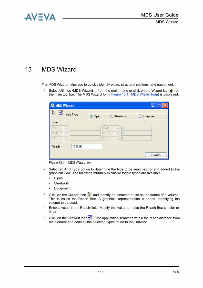
8/13/2019 Multi-Discipline Supports User Guide
http://slidepdf.com/reader/full/multi-discipline-supports-user-guide 111/125
MDS User Guide
MDS Wizard
12.013:1
13 MDS Wizard
The MDS Wizard helps you to quickly identify pipes, structural sections, and equipment.
1. Select Utilities>MDS Wizard… from the main menu or click on the Wizard icon onthe main tool bar. The MDS Wizard form (Figure 13:1.: MDS Wizard form) is displayed.
Figure 13:1. MDS Wizard form
2. Select an Add Type option to determine the type to be searched for and added to thegraphical view. The following mutually exclusive toggle types are available:
• Pipes
• Steelwork
• Equipment
3. Click on the Cursor icon and identify an element to use as the datum of a volume.This is called the Reach Box. A graphical representation is added, identifying the
volume to be used.
4. Enter a value in the Reach field. Modify this value to make the Reach Box smaller or larger.
5. Click on the Drawlist icon . The application searches within the reach distance fromthe element and adds all the selected types found to the Drawlist.

8/13/2019 Multi-Discipline Supports User Guide
http://slidepdf.com/reader/full/multi-discipline-supports-user-guide 112/125
12.013:2
MDS User Guide
MDS Wizard
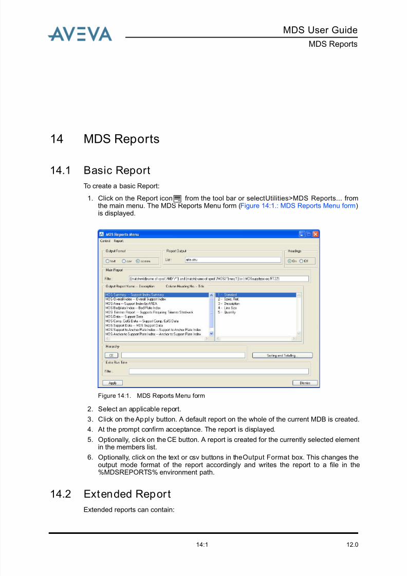
8/13/2019 Multi-Discipline Supports User Guide
http://slidepdf.com/reader/full/multi-discipline-supports-user-guide 113/125
MDS User Guide
MDS Reports
12.014:1
14 MDS Reports
14.1 Basic Report
To create a basic Report:
1. Click on the Report icon from the tool bar or select Utilities>MDS Reports... fromthe main menu. The MDS Reports Menu form (Figure 14:1.: MDS Reports Menu form)is displayed.
Figure 14:1. MDS Reports Menu form
2. Select an applicable report.
3. Click on the Apply button. A default report on the whole of the current MDB is created.
4. At the prompt confirm acceptance. The report is displayed.
5. Optionally, click on the CE button. A report is created for the currently selected elementin the members list.
6. Optionally, click on the text or csv buttons in the Output Format box. This changes theoutput mode format of the report accordingly and writes the report to a file in the%MDSREPORTS% environment path.
14.2 Extended Report
Extended reports can contain:
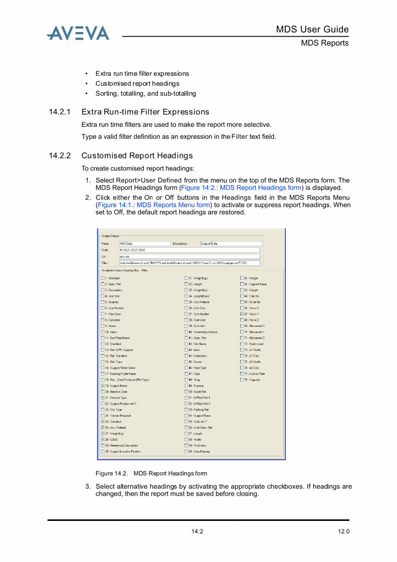
8/13/2019 Multi-Discipline Supports User Guide
http://slidepdf.com/reader/full/multi-discipline-supports-user-guide 114/125
12.014:2
MDS User Guide
MDS Reports
• Extra run time filter expressions
• Customised report headings
• Sorting, totalling, and sub-totalling
14.2.1 Extra Run-time Filter Expressions
Extra run time filters are used to make the report more selective.
Type a valid filter definition as an expression in the Filter text field.
14.2.2 Customised Report Headings
To create customised report headings:
1. Select Report>User Defined from the menu on the top of the MDS Reports form. TheMDS Report Headings form (Figure 14:2.: MDS Report Headings form) is displayed.
2. Click either the On or Off buttons in the Headings field in the MDS Reports Menu(Figure 14:1.: MDS Reports Menu form) to activate or suppress report headings. Whenset to Off, the default report headings are restored.
Figure 14:2. MDS Report Headings form
3. Select alternative headings by activating the appropriate checkboxes. If headings are
changed, then the report must be saved before closing.
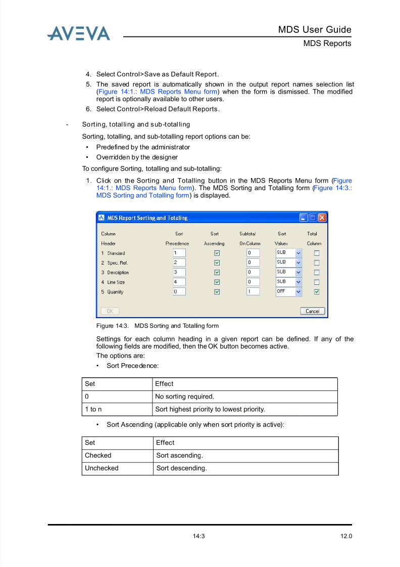
8/13/2019 Multi-Discipline Supports User Guide
http://slidepdf.com/reader/full/multi-discipline-supports-user-guide 115/125
MDS User Guide
MDS Reports
12.014:3
4. Select Control>Save as Default Report.
5. The saved report is automatically shown in the output report names selection list(Figure 14:1.: MDS Reports Menu form) when the form is dismissed. The modified
report is optionally available to other users.6. Select Control>Reload Default Reports.
- Sort ing, total ling and sub-total ling
Sorting, totalling, and sub-totalling report options can be:
• Predefined by the administrator
• Overridden by the designer
To configure Sorting, totalling and sub-totalling:
1. Click on the Sorting and Totalling button in the MDS Reports Menu form (Figure14:1.: MDS Reports Menu form). The MDS Sorting and Totalling form (Figure 14:3.:
MDS Sorting and Totalling form) is displayed.
Figure 14:3. MDS Sorting and Totalling form
Settings for each column heading in a given report can be defined. If any of thefollowing fields are modified, then the OK button becomes active.
The options are:
• Sort Precedence:
• Sort Ascending (applicable only when sort priority is active):
Set Effect
0 No sorting required.
1 to n Sort highest priority to lowest priority.
Set Effect
Checked Sort ascending.
Unchecked Sort descending.
8/13/2019 Multi-Discipline Supports User Guide
http://slidepdf.com/reader/full/multi-discipline-supports-user-guide 116/125
12.014:4
MDS User Guide
MDS Reports
• Subtotal On Column (applicable only when sort priority is active):
• Sort Values:
• Total Column:
2. Click on OK. The form content is checked for validity:
If no inconsistencies are found, then the criteria of the form are accepted.
If inconsistencies are found, then a detailed report is generated and a prompt to correctthe errors is issued.
Set Effect
0 No subtotalling.
1 or n Provides a subtotal of the referenced column number if any
value in that column changes.
Set Effect
ON Values are always output.
OFF Values are never output unless a subtotal for this column is
output.
SUB Values are output if a subtotal for any column is output.
FIRST Values are output for the first occurrence of a group of
common values in a sorted column.
Set Effect
Checked Total for the selected column is output at the bottom of the
report.
Unchecked Total for that column is not output at the bottom of the report.
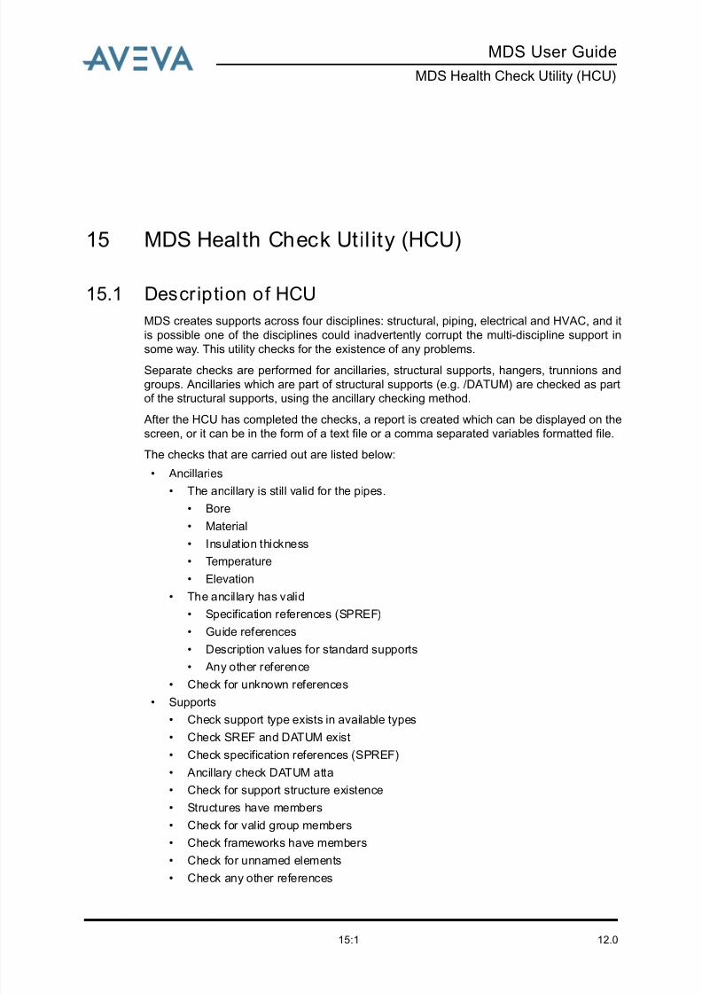
8/13/2019 Multi-Discipline Supports User Guide
http://slidepdf.com/reader/full/multi-discipline-supports-user-guide 117/125
MDS User Guide
MDS Health Check Utility (HCU)
12.015:1
15 MDS Health Check Util ity (HCU)
15.1 Description of HCU
MDS creates supports across four disciplines: structural, piping, electrical and HVAC, and it
is possible one of the disciplines could inadvertently corrupt the multi-discipline support in
some way. This utility checks for the existence of any problems.
Separate checks are performed for ancillaries, structural supports, hangers, trunnions and
groups. Ancillaries which are part of structural supports (e.g. /DATUM) are checked as part
of the structural supports, using the ancillary checking method.
After the HCU has completed the checks, a report is created which can be displayed on the
screen, or it can be in the form of a text file or a comma separated variables formatted file.
The checks that are carried out are listed below:
• Ancillaries
• The ancillary is still valid for the pipes.
• Bore
• Material
• Insulation thickness
• Temperature
• Elevation
• The ancillary has valid
• Specification references (SPREF)
• Guide references
• Description values for standard supports
• Any other reference
• Check for unknown references
• Supports
• Check support type exists in available types
• Check SREF and DATUM exist
• Check specification references (SPREF)
• Ancillary check DATUM atta
• Check for support structure existence
• Structures have members
• Check for valid group members
• Check frameworks have members
• Check for unnamed elements
• Check any other references
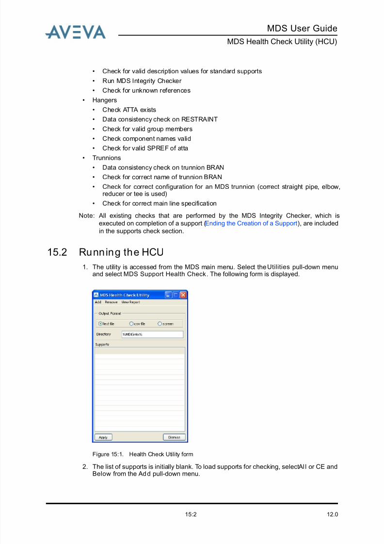
8/13/2019 Multi-Discipline Supports User Guide
http://slidepdf.com/reader/full/multi-discipline-supports-user-guide 118/125
12.015:2
MDS User Guide
MDS Health Check Utility (HCU)
• Check for valid description values for standard supports
• Run MDS Integrity Checker
• Check for unknown references
• Hangers
• Check ATTA exists
• Data consistency check on RESTRAINT
• Check for valid group members
• Check component names valid
• Check for valid SPREF of atta
• Trunnions
• Data consistency check on trunnion BRAN
• Check for correct name of trunnion BRAN
• Check for correct configuration for an MDS trunnion (correct straight pipe, elbow,reducer or tee is used)
• Check for correct main line specification
Note: All existing checks that are performed by the MDS Integrity Checker, which is
executed on completion of a support (Ending the Creation of a Support), are included
in the supports check section.
15.2 Running the HCU
1. The utility is accessed from the MDS main menu. Select the Utilities pull-down menuand select MDS Support Health Check. The following form is displayed.
Figure 15:1. Health Check Utility form
2. The list of supports is initially blank. To load supports for checking, select Al l or CE and
Below from the Add pull-down menu.
8/13/2019 Multi-Discipline Supports User Guide
http://slidepdf.com/reader/full/multi-discipline-supports-user-guide 119/125
MDS User Guide
MDS Health Check Utility (HCU)
12.015:3
The CE and Below option loads all supports below the current element (CE), or if at anelement which is part of a support, e.g. SCTN of a structural support or ROD of ahanger, then that single support is loaded. Groups are counted as one support, and the
group name is displayed in the list (e.g. PS05555, where the group may consist of /PS0555[1], /PS0555[2] etc. The whole group is loaded if one support, or part of onesupport is loaded.
Frameworks with multiple crossbars are counted as one support.
Any supports which are not valid and so cannot be loaded into the list for checking (butare still, in some part or way, MDS supports) are recorded in a temporary load list file,e.g. MDS-HEALTH-CHECK-LOADREPORTONLY-21Mar2007-093214-dat (or csv asappropriate). Unnamed supports are also included in the file.
The load errors file is stored in the %pdmswk% directory and can be viewed byselecting Load Errors Only from the View Report menu.
3. The Remove option allows you to either remove Al l entries in the Supports list, or toremove selected entries from the list.
4. Click on an Output Format option button to select the required format for the healthcheck report. The options are as follows:
• If the screen option is selected, the report is output to the command window.
• If text file is selected, the output is written to a text file (e.g. MDS-HEALTH-CHECK-REPORT-21Mar2007-0931214.dat) in the directory specified in the Directory field.This directory defaults to %projcodeinfo%, where projcode is the Project Code (e.g.TWD). If %projcodeinfo% does not exist, then %pdmswk% is used as the defaultand is displayed in the field. If an invalid directory name is entered, an error alert isdisplayed and the file is not written. If the field is left blank, the default directory isused (%projcodeinfo% if it exists, otherwise %pdmswk%), following an error alert.
The appearance of the text file output is the same as the screen output.
• If CSV file is selected, the same directory rules apply as for a text file, but a csv(comma separated variables) file is created. The file naming convention is the sameas for a text file, except that a .csv extension is used. The csv output representsdata under column headings, and can be viewed in a spreadsheet application (e.g.Excel).
5. Once the supports have been loaded and the output format selected, click on the Apply button to start the health check. Once the check is complete, the report is outputfor screen or file, as described above. In addition to the file described in step 3, atemporary file of the report is also saved in the %pdmswk% directory.
6. View the report by selecting Load Errors Only or Complete Health Check from theView Report menu.
7. Click the Dismiss button to exit the Health Check Utility.
15.3 Example Health Check Report An example of a typical screen/text file output is shown below. The report concludes with a
list of the numbers of errors/warnings found and the number of supports checked.
Example output
************************************************************
MDS Heal t h Check Ut i l i t y Repor t
Date: 27- Sep- 2006
Ti me: 09: 34: 09
User : SYSTEM
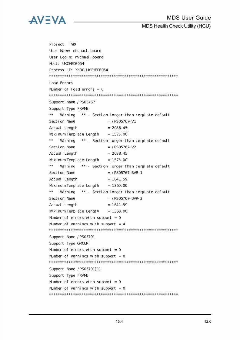
8/13/2019 Multi-Discipline Supports User Guide
http://slidepdf.com/reader/full/multi-discipline-supports-user-guide 120/125
12.015:4
MDS User Guide
MDS Health Check Utility (HCU)
Proj ect : TWD
User Name: mi chael . board
User Logi n: mi chael . boar d
Host : UKCHED3054
Pr ocess I D: Xa30- UKCHED3054
************************************************************
Load Er r ors
Number of l oad er r ors = 0
************************************************************
Suppor t Name / PS05767
Support Type FRAME
** Warni ng ** - Sect i on l onger t han t empl ate def aul t
Sect i on Name = / PS05767- V1
Act ual Length = 2088. 45
Maxi mum Templ at e Length = 1575. 00
** Warni ng ** - Sect i on l onger t han t empl ate def aul t
Sect i on Name = / PS05767- V2
Act ual Length = 2088. 45
Maxi mum Templ at e Length = 1575. 00
** Warni ng ** - Sect i on l onger t han t empl ate def aul t
Sect i on Name = / PS05767- BAR- 1
Act ual Length = 1641. 59
Maxi mum Templ at e Length = 1360. 00
** Warni ng ** - Sect i on l onger t han t empl ate def aul t
Sect i on Name = / PS05767- BAR- 2
Act ual Length = 1641. 59
Maxi mum Templ at e Length = 1360. 00
Number of err ors wi t h suppor t = 0
Number of warni ngs wi t h suppor t = 4
************************************************************
Suppor t Name / PS05791Support Type GROUP
Number of err ors wi t h suppor t = 0
Number of warni ngs wi t h suppor t = 0
************************************************************
Suppor t Name / PS05791[ 1]
Support Type FRAME
Number of err ors wi t h suppor t = 0
Number of warni ngs wi t h suppor t = 0
************************************************************
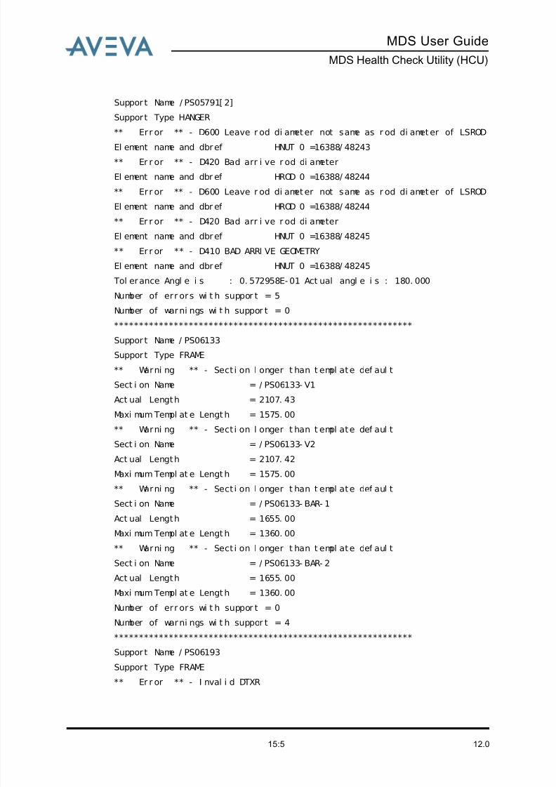
8/13/2019 Multi-Discipline Supports User Guide
http://slidepdf.com/reader/full/multi-discipline-supports-user-guide 121/125
MDS User Guide
MDS Health Check Utility (HCU)
12.015:5
Suppor t Name / PS05791[ 2]
Support Type HANGER
** Err or ** - D600 Leave r od di ameter not same as r od di ameter of LSROD
El ement name and dbref HNUT 0 =16388/ 48243
** Er r or ** - D420 Bad arr i ve r od di ameter
El ement name and dbr ef HROD 0 =16388/ 48244
** Err or ** - D600 Leave r od di ameter not same as r od di ameter of LSROD
El ement name and dbr ef HROD 0 =16388/ 48244
** Er r or ** - D420 Bad arr i ve r od di ameter
El ement name and dbref HNUT 0 =16388/ 48245
** Er r or ** - D410 BAD ARRI VE GEOMETRY
El ement name and dbref HNUT 0 =16388/ 48245
Tol erance Angl e i s : 0. 572958E- 01 Act ual angl e i s : 180. 000
Number of err ors wi t h suppor t = 5
Number of warni ngs wi t h suppor t = 0
************************************************************
Suppor t Name / PS06133
Support Type FRAME
** Warni ng ** - Sect i on l onger t han t empl ate def aul t
Sect i on Name = / PS06133- V1
Act ual Length = 2107. 43
Maxi mum Templ at e Length = 1575. 00
** Warni ng ** - Sect i on l onger t han t empl ate def aul t
Sect i on Name = / PS06133- V2
Act ual Length = 2107. 42
Maxi mum Templ at e Length = 1575. 00
** Warni ng ** - Sect i on l onger t han t empl ate def aul t
Sect i on Name = / PS06133- BAR- 1
Act ual Length = 1655. 00
Maxi mum Templ at e Length = 1360. 00
** Warni ng ** - Sect i on l onger t han t empl ate def aul tSect i on Name = / PS06133- BAR- 2
Act ual Length = 1655. 00
Maxi mum Templ at e Length = 1360. 00
Number of err ors wi t h suppor t = 0
Number of warni ngs wi t h suppor t = 4
************************************************************
Suppor t Name / PS06193
Support Type FRAME
** Er r or ** - I nval i d DTXR
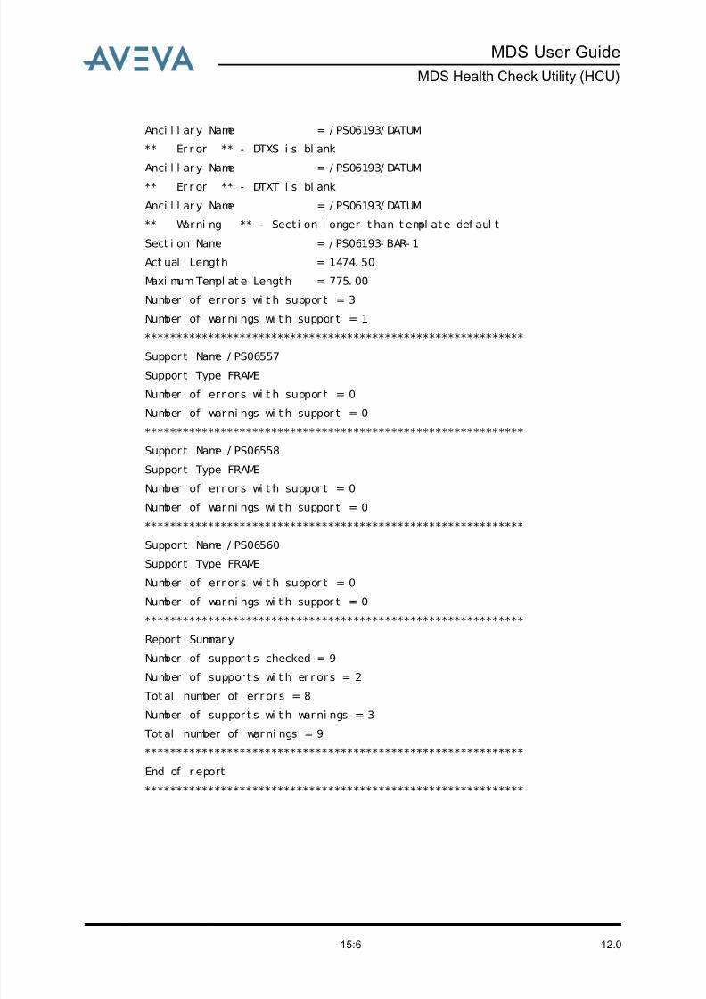
8/13/2019 Multi-Discipline Supports User Guide
http://slidepdf.com/reader/full/multi-discipline-supports-user-guide 122/125
12.015:6
MDS User Guide
MDS Health Check Utility (HCU)
Anci l l ar y Name = / PS06193/ DATUM
** Er r or ** - DTXS i s bl ank
Anci l l ar y Name = / PS06193/ DATUM
** Er r or ** - DTXT i s bl ank
Anci l l ar y Name = / PS06193/ DATUM
** Warni ng ** - Sect i on l onger t han t empl ate def aul t
Sect i on Name = / PS06193- BAR- 1
Act ual Length = 1474. 50
Maxi mum Templ at e Length = 775. 00
Number of err ors wi t h suppor t = 3
Number of warni ngs wi t h suppor t = 1
************************************************************
Suppor t Name / PS06557
Support Type FRAME
Number of err ors wi t h suppor t = 0
Number of warni ngs wi t h suppor t = 0
************************************************************
Suppor t Name / PS06558
Support Type FRAME
Number of err ors wi t h suppor t = 0
Number of warni ngs wi t h suppor t = 0
************************************************************
Suppor t Name / PS06560
Support Type FRAME
Number of err ors wi t h suppor t = 0
Number of warni ngs wi t h suppor t = 0
************************************************************
Repor t Summar y
Number of suppor t s checked = 9
Number of suppor t s wi t h er r ors = 2
Tot al number of er r or s = 8Number of suppor t s wi t h warni ngs = 3
Tot al number of warni ngs = 9
************************************************************
End of r eport
************************************************************

8/13/2019 Multi-Discipline Supports User Guide
http://slidepdf.com/reader/full/multi-discipline-supports-user-guide 123/125
Index
12.0Index page 1
MDS User Guide
A
Add Packer . . . . . . . . . . . . . . . . . . . . . . 2:18
Administration Options . . . . . . . . . . . . . 2:38
Administrator’s Role . . . . . . . . . . . . . . . . 1:2
Align guide to support . . . . . . . . . . . . . . 2:38
Ancillary Selection . . . . . . . . . . . . . . . . . 2:10
Application defaults
modifying . . . . . . . . . . . . . . . . . . . . 2:37
Associate pad with shoe . . . . . . . . . . . . 2:38 Automatic Steelwork Orientation . . . . . . 2:35
Autonaming . . . . . . . . . . . . . . . . . . . . . . . 2:8
B
Branch reinforcement
creating . . . . . . . . . . . . . . . . . . . . . . . 6:1
C
CE button . . . . . . . . . . . 2:31, 2:35, 5:8, 8:4
Connections to external steelwork . . . . 2:19Copying a support . . . . . . . . . . . . . . . . . 2:31
Create by Clearance . . . . . . . . . . . . . . . 2:15
Create by Cursor . . . . . . . . . . . . . . . . . . 2:13
Create by Dimensions . . . . . . . . . . . . . . 2:16
Create Connections . . . . . . . . . . . . . . . 2:19
Create datum support atta button 2:10, 6:2, 7:2
Creating
hanger . . . . . . . . . . . . . . . . . . . . . . . 5:1
lighting support . . . . . . . . . . . . . . . . . 8:1
project special support . . . . . . . . . . 2:43
special SCTN . . . . . . . . . . . . . . . . . 2:46
special support . . . . . . . . . . . 2:39, 2:42
support . . . . . . . . . . . . . . . . . . . . . . . 2:4
trunnion . . . . . . . . . . . . . . . . . . . . . . 4:1
D
Data Access Control . . . . . . . . . . . . . . 11:1
Data sheets
MDS application . . . . . . . . . . . . . . . 12:1
Datum atta . . . . . . . . . . . . . . . . . . . . . . 2:10
Default Creation Zone . . . . . . . . . . . . . . 2:9
Default Creation Zone form . . . . . . . . . . 2:3
Deleting a support . . . . . . . . . . . . . . . . 2:30
Distance button . . . . . . .2:11, 5:7, 5:16, 7:2
Drawing Note
adding . . . . . . . . . . . . . . . . . . . . . . 2:37
Drawlist
adding a support . . . . . . . . . . . . . . 2:38
E
Error message . . . . . . . . . . . . . . . . . . . 2:27
H
Hanger
changing from fixed to variable . . . 5:11
changing rod lengths . . . . . . . . . . . 5:10
creating . . . . . . . . . . . . . . . . . . . . . . 5:1
modifying . . . . . . . . . . . . . . . . . . . . . 5:8
modifying the configuration . . . . . . 5:11
reconnecting to new steelwork . . . 5:13
rotating all members . . . . . . . . . . . . 5:9
rotating one member . . . . . . . . . . . . 5:9
Hanger configurations . . . . . . . . . . . 5:2, 5:4
Hanger creation mode . . . . . . . . . . . . . . 5:5
Hanger types . . . . . . . . . . . . . . . . . . . . . 5:3
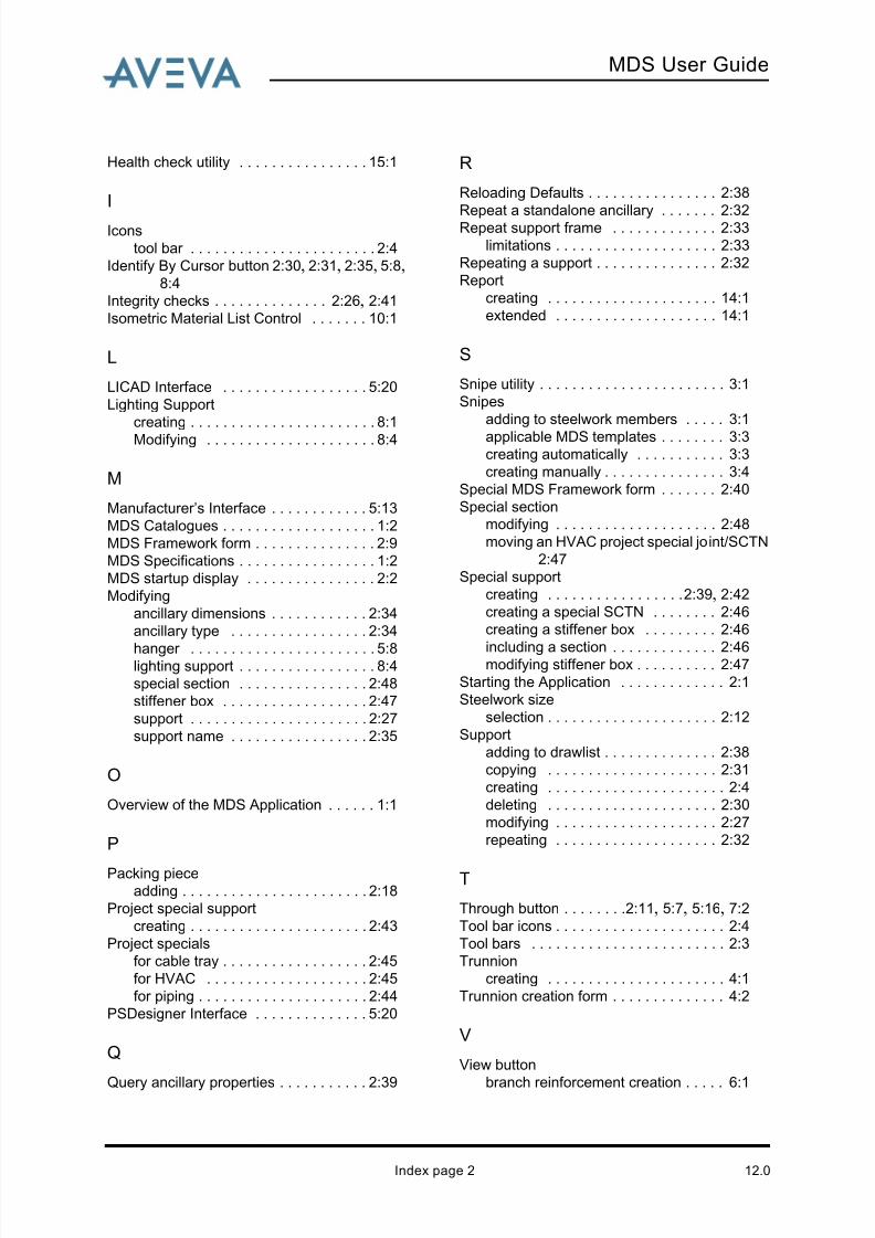
8/13/2019 Multi-Discipline Supports User Guide
http://slidepdf.com/reader/full/multi-discipline-supports-user-guide 124/125
MDS User Guide
12.0Index page 2
Health check utility . . . . . . . . . . . . . . . . 15:1
I
Icons
tool bar . . . . . . . . . . . . . . . . . . . . . . . 2:4
Identify By Cursor button 2:30, 2:31, 2:35, 5:8,8:4
Integrity checks . . . . . . . . . . . . . . 2:26, 2:41
Isometric Material List Control . . . . . . . 10:1
L
LICAD Interface . . . . . . . . . . . . . . . . . . 5:20
Lighting Support
creating . . . . . . . . . . . . . . . . . . . . . . . 8:1
Modifying . . . . . . . . . . . . . . . . . . . . . 8:4
M
Manufacturer’s Interface . . . . . . . . . . . . 5:13
MDS Catalogues . . . . . . . . . . . . . . . . . . . 1:2
MDS Framework form . . . . . . . . . . . . . . . 2:9
MDS Specifications . . . . . . . . . . . . . . . . . 1:2
MDS startup display . . . . . . . . . . . . . . . . 2:2
Modifying
ancillary dimensions . . . . . . . . . . . . 2:34
ancillary type . . . . . . . . . . . . . . . . . 2:34
hanger . . . . . . . . . . . . . . . . . . . . . . . 5:8lighting support . . . . . . . . . . . . . . . . . 8:4
special section . . . . . . . . . . . . . . . . 2:48
stiffener box . . . . . . . . . . . . . . . . . . 2:47
support . . . . . . . . . . . . . . . . . . . . . . 2:27
support name . . . . . . . . . . . . . . . . . 2:35
O
Overview of the MDS Application . . . . . . 1:1
P
Packing piece
adding . . . . . . . . . . . . . . . . . . . . . . . 2:18
Project special support
creating . . . . . . . . . . . . . . . . . . . . . . 2:43
Project specials
for cable tray . . . . . . . . . . . . . . . . . . 2:45
for HVAC . . . . . . . . . . . . . . . . . . . . 2:45
for piping . . . . . . . . . . . . . . . . . . . . . 2:44
PSDesigner Interface . . . . . . . . . . . . . . 5:20
Q
Query ancillary properties . . . . . . . . . . . 2:39
R
Reloading Defaults . . . . . . . . . . . . . . . . 2:38
Repeat a standalone ancillary . . . . . . . 2:32Repeat support frame . . . . . . . . . . . . . 2:33
limitations . . . . . . . . . . . . . . . . . . . . 2:33
Repeating a support . . . . . . . . . . . . . . . 2:32
Report
creating . . . . . . . . . . . . . . . . . . . . . 14:1
extended . . . . . . . . . . . . . . . . . . . . 14:1
S
Snipe utility . . . . . . . . . . . . . . . . . . . . . . . 3:1
Snipes
adding to steelwork members . . . . . 3:1
applicable MDS templates . . . . . . . . 3:3creating automatically . . . . . . . . . . . 3:3
creating manually . . . . . . . . . . . . . . . 3:4
Special MDS Framework form . . . . . . . 2:40
Special section
modifying . . . . . . . . . . . . . . . . . . . . 2:48
moving an HVAC project special joint/SCTN 2:47
Special support
creating . . . . . . . . . . . . . . . . . 2:39, 2:42
creating a special SCTN . . . . . . . . 2:46
creating a stiffener box . . . . . . . . . 2:46
including a section . . . . . . . . . . . . . 2:46modifying stiffener box . . . . . . . . . . 2:47
Starting the Application . . . . . . . . . . . . . 2:1
Steelwork size
selection . . . . . . . . . . . . . . . . . . . . . 2:12
Support
adding to drawlist . . . . . . . . . . . . . . 2:38
copying . . . . . . . . . . . . . . . . . . . . . 2:31
creating . . . . . . . . . . . . . . . . . . . . . . 2:4
deleting . . . . . . . . . . . . . . . . . . . . . 2:30
modifying . . . . . . . . . . . . . . . . . . . . 2:27
repeating . . . . . . . . . . . . . . . . . . . . 2:32
T
Through button . . . . . . . .2:11, 5:7, 5:16, 7:2
Tool bar icons . . . . . . . . . . . . . . . . . . . . . 2:4
Tool bars . . . . . . . . . . . . . . . . . . . . . . . . 2:3
Trunnion
creating . . . . . . . . . . . . . . . . . . . . . . 4:1
Trunnion creation form . . . . . . . . . . . . . . 4:2
V
View button
branch reinforcement creation . . . . . 6:1
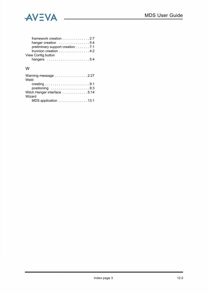
8/13/2019 Multi-Discipline Supports User Guide
http://slidepdf.com/reader/full/multi-discipline-supports-user-guide 125/125
MDS User Guide
framework creation . . . . . . . . . . . . . . 2:7
hanger creation . . . . . . . . . . . . . . . . 5:4
preliminary support creation . . . . . . . 7:1
trunnion creation . . . . . . . . . . . . . . . . 4:2View Config button
hangers . . . . . . . . . . . . . . . . . . . . . . 5:4
W
Warning message . . . . . . . . . . . . . . . . . 2:27
Weld
creating . . . . . . . . . . . . . . . . . . . . . . . 9:1
positioning . . . . . . . . . . . . . . . . . . . . 9:3
Witch Hanger interface . . . . . . . . . . . . . 5:14
Wizard
MDS application . . . . . . . . . . . . . . . 13:1