MULTI-DEGREE of FREEDOM SYSTEMS (MDOF)w3.gazi.edu.tr/~ksoyluk/resimler/IM 508 MDOF.pdf ·...
31
MULTI-DEGREE of FREEDOM SYSTEMS (MDOF) In many cases, it is necessary to use many coordinates to adequetly describe the configuration of the structure and the deformed shape. Such systems are said to be multi-DOF discrete systems. Fig. shows a beam whose movement is defined by the displacements u 1 (t), u 2 (t),……. u i (t),……, u n (t) of n points. These points can be placed arbitrarily along the beam and necessarily at places where there are changes in the geometry of the beam or the distribution of the loading. The set of displacements associated with the n points constitutes the number of DOFs of the system.
-
Upload
hoangkhuong -
Category
Documents
-
view
221 -
download
0
Transcript of MULTI-DEGREE of FREEDOM SYSTEMS (MDOF)w3.gazi.edu.tr/~ksoyluk/resimler/IM 508 MDOF.pdf ·...

MULTI-DEGREE of FREEDOM SYSTEMS (MDOF)
In many cases, it is necessary to use many coordinates to adequetly
describe the configuration of the structure and the deformed shape.
Such systems are said to be multi-DOF discrete systems.
Fig. shows a beam whose movement is defined by the displacements
u1(t), u2(t),……. ui(t),……, un(t) of n points. These points can be placed
arbitrarily along the beam and necessarily at places where there are
changes in the geometry of the beam or the distribution of the loading.
The set of displacements associated with the n points constitutes the
number of DOFs of the system.
Simplified Model of a Building
Consider the three-story building shown in
Fig. Assumptions:
The mass of the columns are negligible
when compared to the total mass of the
building, which is concentrated at the floor
levels.
The floor and the beams are rigid in
longitudinal direction and in flexure.
The columns are infinitely stiff axially but
flexible transversally.
From these assumptions it can be
concluded that the building has only a shear
deformation mode in the transverse direction.
This simplified model of the building is called
a shear building idealization.

Simplified Model of a Building
Consider the free-body diagram shown in Fig.

Assuming a linear system, the elastic forces fs can be related to the floor
displacements u.
For this purpose we introduce the lateral stiffness kj of the jth story; it relates
the story shear Vj to the story deformation or drift, j=uj-uj-1, by
)(
)(
)(
3333
2222
1111
tpfff
tpfff
tpfff
SDI
SDI
SDI
(1)
jjj kV
The story stiffness is the sum of the lateral stiffnessess of all columns in the
story. For a story height of h and a column with modulus E and second
moment of area Ic, the lateral stiffness of a column with clamped ends,
implied by the shear-building idealization, is 12EIc/h3. Thus the story
stiffness is
columns
cj
h
EIk
3
12
The equations of equilibrium of the three masses are,

)(
)()(
)(
23333
323122222
21211111
uukff
uukuukfff
uukukfff
i
SS
s
S
i
SS
s
S
i
SS
(2)
Similarly, the damping forces fDi can be written with respect to the relative
velocities of the DOFs u
)(
)()(
)(
23333
323122222
21211111
uucff
uucuucfff
uucucfff
i
DD
s
D
i
DD
s
D
i
DD
(3)
We can relate the elastic forces fsi to the relative floor displacements ui.
The force fsi at the first floor is made up of two contributions: fsis above
and fsii below the first story. Thus,
s
S
i
SS fff 111
Considering Vj=jkj, and noting that 1=u1 and 2=u2-u1
)( 212111 uukukfS
Similarly, the forces fs2 and fs3 will be determined as,
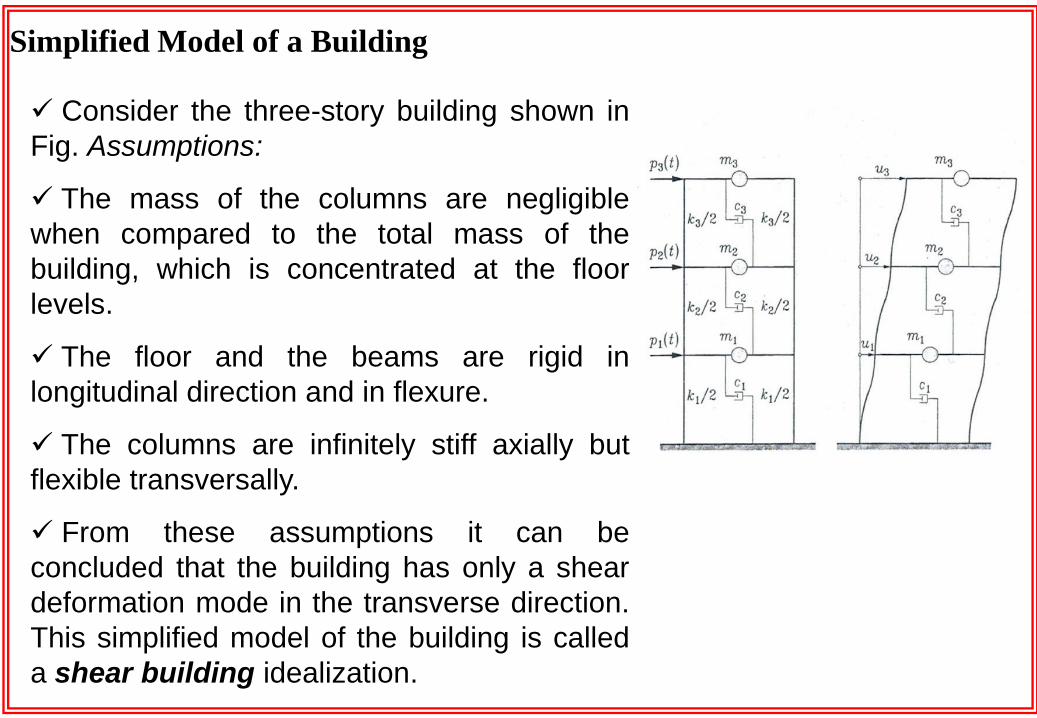
The inertia forces associated with the masses m1, m2 and m3 undergoing
accelerations ü1, ü1 and ü3, respectively, can be written
333
222
111
umf
umf
umf
I
I
I
(4)
After substitution of Equations (2), (3) and (4) into Eq. (1), we get:
)()()(
)()()()()(
)()()(
323323333
232312232312222
1212112121111
tpuukuucum
tpuukuukuucuucum
tpuukukuucucum
(5)
which can be written in the matrix equation as,
)(tpfff SDI

in which fI is the vector of inertia forces
3
2
1
3
2
1
00
00
00
u
u
u
m
m
m
uMf I
(6)
in which fD is the vector of damping forces
(7)
and fS is the vector of elastic forces
3
2
1
33
3322
221
0
0
u
u
u
cc
cccc
ccc
uCfD
3
2
1
33
3322
221
0
0
u
u
u
kk
kkkk
kkk
KufS (8)
Eq. (5) becomes*,
)()()()( tptKutuCtuM (9)

Equation of Dynamic Equilibrium
It can be concluded that the dynamic equation of equilibrium of a discrete
multi-DOF system written in matrix form is entirely equivalent to the
SDOF system one, with each term replaced by a vector or a matrix of
order equal to the number of DOFs n as follows:
)(tpfff SDI (10)
in which,
)(
)(
)(
tKuf
tuCf
tuMf
S
D
I
(11)
Hence,
)()()()( tptKutuCtuM (12)

Eq. (12) expressess the dynamic equation of equilibrium of a discrete
multi-DOF system. fI, fD and fS represent the vectors of inertia forces,
damping forces and elastic forces, respectively. Each system of forces is a
summation of a set of influence coefficients mij, cij and kij whose definitions
are:
The stiffness influence coefficient kij is the force in the direction of DOF i,
caused by a unit displacement imposed in the direction of DOF j, while
displacements in the direction of all other DOFs are kept equal to zero. The
matrix of all stiffness influence coefficients K is called the stiffness matrix.
The stiffness influence coefficient cij is the force in the direction of DOF i,
caused by a unit velocity imparted in the direction of DOF j, while velocities
in the direction of all other DOFs are kept equal to zero. The matrix of all
damping influence coefficients C is called the damping matrix.
The stiffness influence coefficient mij is the force in the direction of DOF i,
caused by a unit acceleration imparted in the direction of DOF j, while
accelerations in the direction of all other DOFs are kept equal to zero. The
matrix of all mass influence coefficients M is called the mass matrix.

By definition, the stiffness influence coefficient kij is the force in along
DOF i due to a unit displacement imposed along DOF j, while keeping all
other displacements equal to zero.
The stiffness influence coefficients are numerically equal to the applied
forces required to maintain the specified displacement condition. They are
positive when the sense of the applied force corresponds to a positive
displacement and negative otherwise.
If we know the fixed-end reactions caused by unit displacements
imposed at any one support in a given direction, we can easily determine
the coefficients kij.
Fig. summarizes the stiffness influence coefficients for a flexural
structural element**.
Stiffness Influence Coefficients

Example: Calculate the stiffness matrix of the building shown in Fig. using
a shear building idealization. Write the equation of motion assuming that
the system has no damping.

The mass matrix is diagonal and is written as,
m
mM
0
0
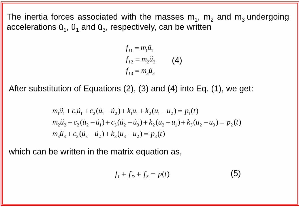
By successively imposing a unit displacement to DOFs 1 and 2 while
keeping the displacement along the other DOF equal to zero, we obtain
3
2
3
111
2424
h
EI
h
EIk
3
221
24
h
EIk
3
212
24
h
EIk
3
222
24
h
EIk
Hence, the stiffness matrix of the structure is
2221
1211
kk
kkK
22
221
3
224
EIEI
EIEIEI
h
EIK
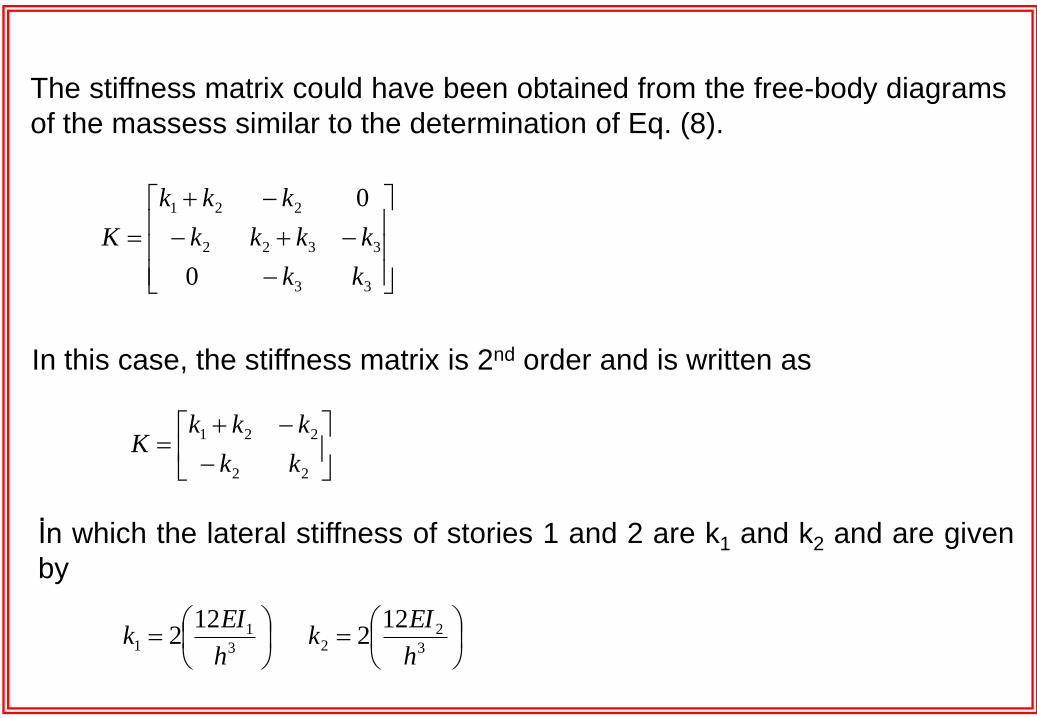
The stiffness matrix could have been obtained from the free-body diagrams
of the massess similar to the determination of Eq. (8).
3
11
122
h
EIk
In this case, the stiffness matrix is 2nd order and is written as
33
3322
221
0
0
kk
kkkk
kkk
K
22
221
kk
kkkK
İn which the lateral stiffness of stories 1 and 2 are k1 and k2 and are given
by
3
22
122
h
EIk

The equations of motion of the building in matrix form are
The stiffness of a building idealized as a shear building is always larger
than the actual stiffness because additional constraints on the rotations of
the node are introduced. This leads to an overestimation of the frequencies
which are proportional to the stiffness.
)(
)(24
0
0
2
1
2
1
22
221
3
2
1
tp
tp
u
u
EIEI
EIEIEI
hu
u
m
m

The axial stiffness of the columns and the beams can be assumed to be
infinitely stiff. The frame has six DOFs numbered as shown in Fig. DOFs u1
and u2 are are translational while DOFs u3 to u6 are rotational. The
equation of motion can be written as
Example: Write the equation of motion of the two-story building shown in
Fig. considering the flexibility of the beams and rotations of the nodes.
)(tpKuuM

where the nodal displacement and acceleration vectors are
)(
)(
)(
)(
)(
)(
6
5
4
3
2
1
tu
tu
tu
tu
tu
tu
u
)(
)(
)(
)(
)(
)(
6
5
4
3
2
1
tu
tu
tu
tu
tu
tu
u
Considering that the mass moment of inertia are negligible, the mass
matrix is diagonal and contains only two non-zero terms on the diagonal
corresponding to DOFs u1 and u2. The mass matrix is
0
0
0
0
m
m
M

and the dynamic load vector is
)(
)(
)(
)(
)(
)(
)(
6
5
4
3
2
1
tp
tp
tp
tp
tp
tp
tp
Determination of the influence coefficient kij will be done by imposing
successively a unit displacement to DOFs 1 to 6 while keeping
displacements of all other DOFs equal to zero.
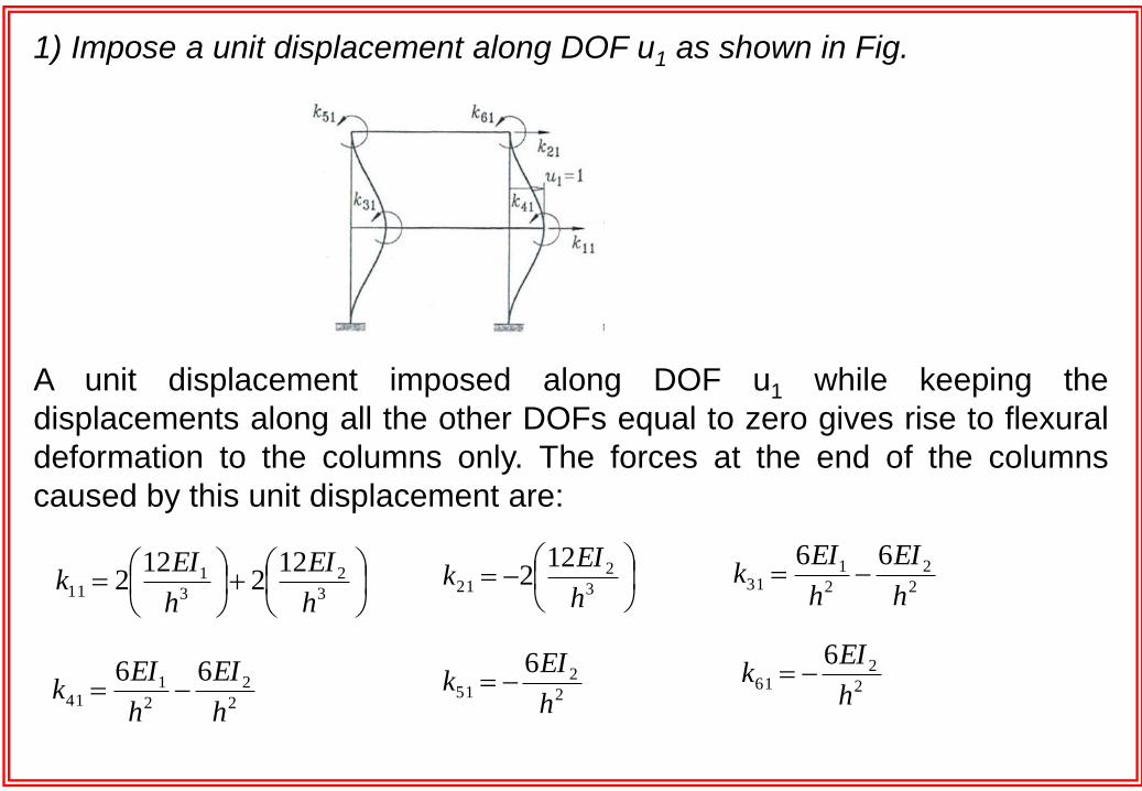
1) Impose a unit displacement along DOF u1 as shown in Fig.
A unit displacement imposed along DOF u1 while keeping the
displacements along all the other DOFs equal to zero gives rise to flexural
deformation to the columns only. The forces at the end of the columns
caused by this unit displacement are:
3
2
3
111
122
122
h
EI
h
EIk
3
221
122
h
EIk 2
2
2
131
66
h
EI
h
EIk
2
2
2
141
66
h
EI
h
EIk 2
251
6
h
EIk 2
261
6
h
EIk

2) Impose a unit displacement along DOF u2 as shown in Fig.
A unit displacement imposed along DOF u2 while keeping the
displacements along all the other DOFs equal to zero gives rise to flexural
deformation to the columns of the second story only. The forces at the end
of the columns caused by this unit displacement are:
3
212
122
h
EIk
3
222
122
h
EIk 2
232
6
h
EIk
2
242
6
h
EIk 2
252
6
h
EIk
2
262
6
h
EIk
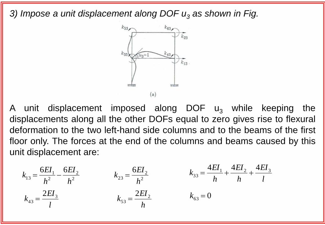
3) Impose a unit displacement along DOF u3 as shown in Fig.
A unit displacement imposed along DOF u3 while keeping the
displacements along all the other DOFs equal to zero gives rise to flexural
deformation to the two left-hand side columns and to the beams of the first
floor only. The forces at the end of the columns and beams caused by this
unit displacement are:
l
EI
h
EI
h
EIk 321
33
444
l
EIk 3
43
2
h
EIk 2
53
2 063 k
2
223
6
h
EIk
2
2
2
113
66
h
EI
h
EIk

4) Impose a unit displacement along DOF u4 as shown in Fig.
A unit displacement imposed along DOF u4 while keeping the
displacements along all the other DOFs equal to zero gives rise to flexural
deformation to the two right-hand side columns and to the beams of the
first floor only. The forces at the end of the columns and beams caused by
this unit displacement are:
l
EI
h
EI
h
EIk 321
44
444
l
EIk 3
34
2
h
EIk 2
64
2054 k
2
224
6
h
EIk 2
2
2
114
66
h
EI
h
EIk

5) Impose a unit displacement along DOF u5 as shown in Fig.
A unit displacement imposed along DOF u5 while keeping the
displacements along all the other DOFs equal to zero gives rise to flexural
deformation to the two left-hand side column in the second story and to the
beam at the roof level only. The forces at the end of this column and this
beam caused by the imposed unit displacement are:
l
EI
h
EIk 42
55
44
h
EIk 2
35
2
l
EIk 4
65
2045 k
2
225
6
h
EIk
2
215
6
h
EIk
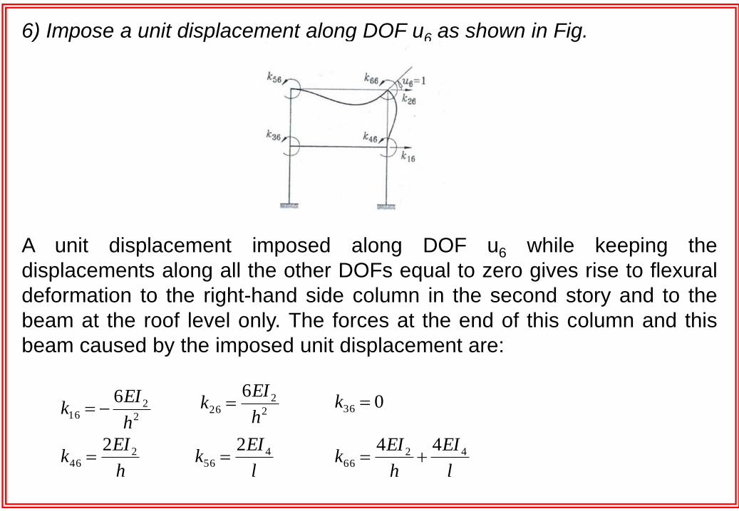
6) Impose a unit displacement along DOF u6 as shown in Fig.
A unit displacement imposed along DOF u6 while keeping the
displacements along all the other DOFs equal to zero gives rise to flexural
deformation to the right-hand side column in the second story and to the
beam at the roof level only. The forces at the end of this column and this
beam caused by the imposed unit displacement are:
l
EIk 4
56
2
036 k
l
EI
h
EIk 42
66
44
2
226
6
h
EIk
2
216
6
h
EIk
h
EIk 2
46
2
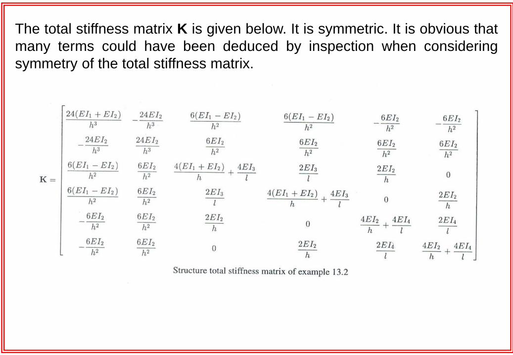
The total stiffness matrix K is given below. It is symmetric. It is obvious that
many terms could have been deduced by inspection when considering
symmetry of the total stiffness matrix.
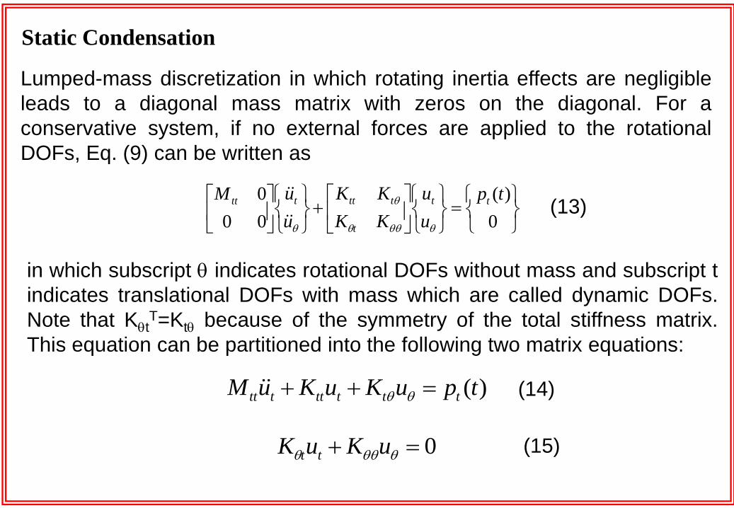
Lumped-mass discretization in which rotating inertia effects are negligible
leads to a diagonal mass matrix with zeros on the diagonal. For a
conservative system, if no external forces are applied to the rotational
DOFs, Eq. (9) can be written as
Static Condensation
0
)(
00
0 tp
u
u
KK
KK
u
uM tt
t
tttttt
in which subscript indicates rotational DOFs without mass and subscript t
indicates translational DOFs with mass which are called dynamic DOFs.
Note that KtT=Kt because of the symmetry of the total stiffness matrix.
This equation can be partitioned into the following two matrix equations:
)(tpuKuKuM tttttttt (14)
(13)
0 uKuK tt(15)

Because there are no inertia forces in Eq. (15), we can deduce the
following static relation between u and ut:
Substituting Eq. (16) into Eq. (14), we obtain
)(tpuKuM ttttt
(18)
(16) ttuKKu
(17)
in which the double subscript of Mtt has been replaced by the subscript t
since there is no ambiguity and where
ttttt KKKKK 1
Matrix Kt is called reduced or condensed stiffness matrix and corresponds
to the translational stiffness matrix.
The solution of Eq. (17) gives the displacements of the dynamic DOFs ut(t).
The displacements of the condensed DOFs, u(t), can be deduced from
Eq. (16) knowing ut(t).
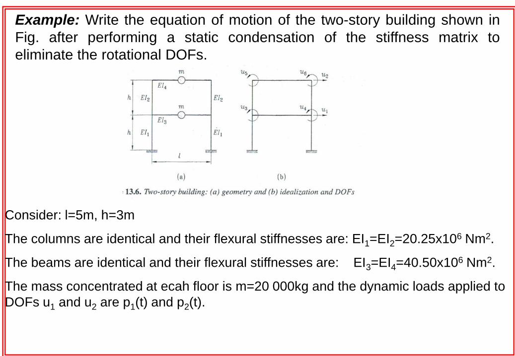
Consider: l=5m, h=3m
The columns are identical and their flexural stiffnesses are: EI1=EI2=20.25x10⁶ Nm2.
The beams are identical and their flexural stiffnesses are: EI3=EI4=40.50x10⁶ Nm2.
The mass concentrated at ecah floor is m=20 000kg and the dynamic loads applied to
DOFs u1 and u2 are p1(t) and p2(t).
Example: Write the equation of motion of the two-story building shown in
Fig. after performing a static condensation of the stiffness matrix to
eliminate the rotational DOFs.

The stiffness matrix corresponding to the six DOFs can be determined as,
We will make use of the stiffness matrix presented in the previous example:
4.592.165.1305.135.13
2.164.5905.135.135.13
5.1304.862.165.130
05.132.164.865.130
5.135.135.135.130.180.18
5.135.13000.180.36
106
KK
KKK
t
ttt

Let us partition this matrix into four sub-matrices: Ktt, Kt, Kt and K:
We mass matrix and the dynamic load vector are,
NKK T
tt
5.135.135.135.13
5.135.1300106
)(
)()(
2
1
tp
tptpt
10
011020 3xM t
mNKtt /1818
1836106
NmK
4.592.165.130
2.164.5905.13
5.1304.862.16
05.132.164.86
106

The equation of motion is,
Hence, the condensed stiffness matrix is,
mNKKKKK t
T
tttt /72377.1071222.13
71222.1306256.311061
)(
)(
)(
)(
72377.1071222.13
71222.1306256.3110
)(
)(
10
011020
2
1
2
16
2
13
tp
tp
tu
tu
tu
tux