Multi-Cycle MIPS Processor...
6
1 Multi-Cycle MIPS Processor Model Fares Elsabbagh January 22, 2019 Table of Contents 1. VHDL CODE WALK-THROUGH ........................................................................................................................2 2 EXTENDING THE MULTI-CYCLE DATAPATH MODEL TO SUPPORT SW INSTRUCTIONS ....................................6
Transcript of Multi-Cycle MIPS Processor...

1
Multi-Cycle MIPS Processor Model
Fares Elsabbagh
January 22, 2019
Table of Contents 1. VHDL CODE WALK-THROUGH ........................................................................................................................2 2 EXTENDING THE MULTI-CYCLE DATAPATH MODEL TO SUPPORT SW INSTRUCTIONS ....................................6
2
The following describes the multi-cycle MIPS processor model. A brief code walkthrough helps establish the correspondence between the VHDL model and the multi-cycle data-path slides. We have tried to keep a correspondence between the signals in the datapath and the figure. Read the header for model constraints, e.g., supported instructions. You are also encouraged to go through the following with colleagues as a study exercise to understand the VHDL model.
1. VHDL Code Walk-through Similar to the single cycle data-path model, the multi-cycle model has an IRAM and DRAM memory arrays. Both these arrays are word addressable.
Figure 1
3
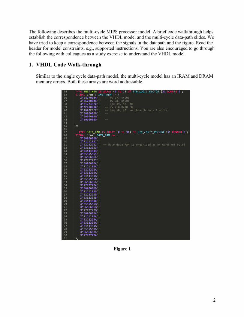
However, unlike the single cycle model, this model has an IROM.
Figure 2
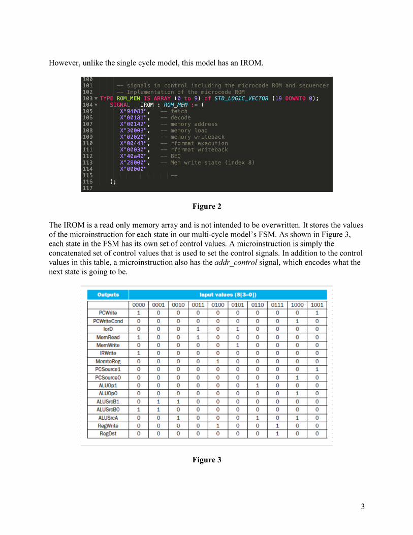
The IROM is a read only memory array and is not intended to be overwritten. It stores the values of the microinstruction for each state in our multi-cycle model’s FSM. As shown in Figure 3, each state in the FSM has its own set of control values. A microinstruction is simply the concatenated set of control values that is used to set the control signals. In addition to the control values in this table, a microinstruction also has the addr_control signal, which encodes what the next state is going to be.
Figure 3
4
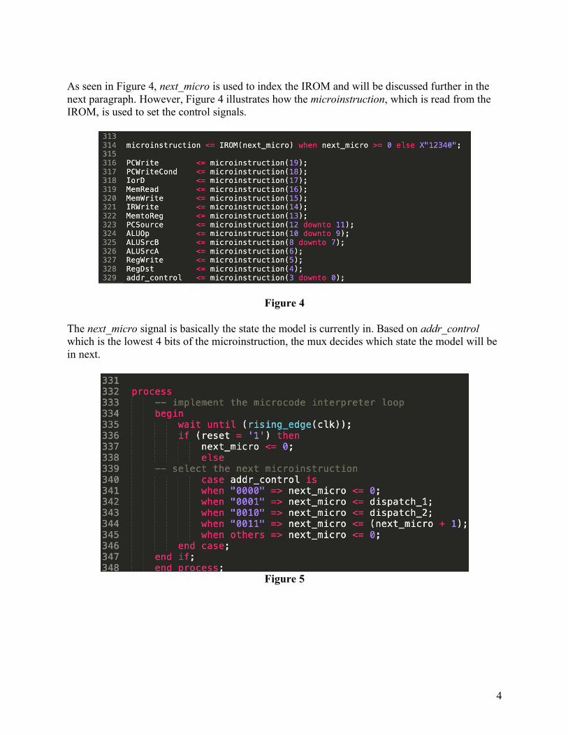
As seen in Figure 4, next_micro is used to index the IROM and will be discussed further in the next paragraph. However, Figure 4 illustrates how the microinstruction, which is read from the IROM, is used to set the control signals.
Figure 4 The next_micro signal is basically the state the model is currently in. Based on addr_control which is the lowest 4 bits of the microinstruction, the mux decides which state the model will be in next.
Figure 5
5
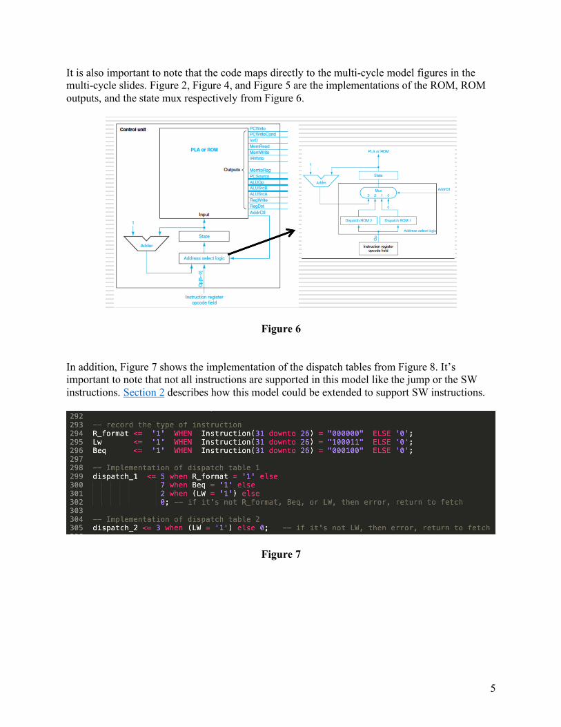
It is also important to note that the code maps directly to the multi-cycle model figures in the multi-cycle slides. Figure 2, Figure 4, and Figure 5 are the implementations of the ROM, ROM outputs, and the state mux respectively from Figure 6.
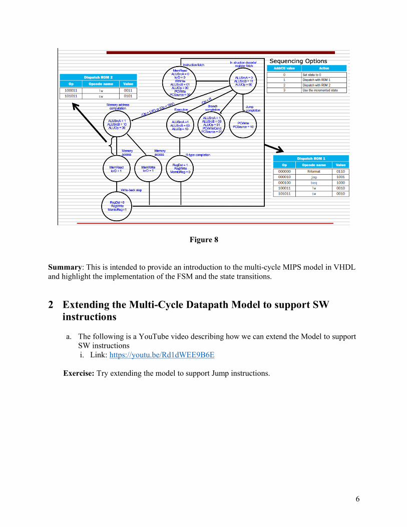
Figure 6 In addition, Figure 7 shows the implementation of the dispatch tables from Figure 8. It’s important to note that not all instructions are supported in this model like the jump or the SW instructions. Section 2 describes how this model could be extended to support SW instructions.
Figure 7
6
Figure 8 Summary: This is intended to provide an introduction to the multi-cycle MIPS model in VHDL and highlight the implementation of the FSM and the state transitions.
2 Extending the Multi-Cycle Datapath Model to support SW instructions a. The following is a YouTube video describing how we can extend the Model to support
SW instructions i. Link: https://youtu.be/Rd1dWEE9B6E
Exercise: Try extending the model to support Jump instructions.