Parallel and Distributed Intelligent Systems: Multi-Agent Systems and e-Commerce

The Pennsylvania State University
The Graduate School
School of Science, Engineering and Technology
MULTI-AGENT BASED INTELLIGENT DISTRIBUTED CONTROL
OF A HARDWARE-IN-THE-LOOP
MICROGRID TEST-BED
A Thesis in
Electrical Engineering
by
Ameya Pradeep Chandrayan
2015 Ameya Pradeep Chandrayan
Submitted in Partial Fulfillment
of the Requirements
for the Degree of
Master of Science
August 2015

ii
The thesis of Ameya Pradeep Chandrayan was reviewed and approved* by the following:
Peter Idowu
Professor, Department of Electrical Engineering
Thesis Advisor
Scott van Tonningen
Senior Lecturer, Department of Electrical Engineering
Seth Wolpert
Associate Professor, Department of Electrical Engineering
Jeremy J Blum
Associate Professor, Department of Computer and Mathematical Sciences
Sedig Agili
Graduate Program Coordinator
*Signatures are on file in the Graduate School

iii
Abstract
The structure of conventional electric power systems is changing its course from few
centralized entities to numerous distributed energy systems, leading to technological challenges in
three key aspects – sustainability, flexibility, and reliability. Penetration of renewable energy
resources into the power system seems to magnify these challenges, and requires tremendous
efforts to develop new control and protection methodologies, and market policies. Various interest
groups including the government, electric utilities, academic and research institutions, as well as
consumers are actively working towards the goal of a new intelligent grid – ‘smart grid’. This
research focuses on the development of an operation and control scheme for a laboratory-scale
hardware-in-the-loop microgrid system. The main features of this microgrid system include
integrated renewable energy systems, battery storage, smart loads to realize demand-side energy
management for various load patterns, advanced digital relays, as well as smart energy metering
devices interfaced through various communication channels and protocols. Conventional
generating units synchronized to an AC bus are coupled to the energy storage and the PV system
through a DC bus. In real-life microgrid systems, various synchronous, asynchronous and static
sources of power generation are dispersed geographically but relatively close to the demand side.
An implementation of conventional power grid control and operation methods would presumably
demand very high speed central processing platforms to perform extensive computations required
for such a dispersed system. On the other hand, distributed control methods allocate these number
crunching operations to asynchronous and autonomous control platforms, which operate in
harmony to provide reliability, flexibility and resiliency in the microgrid environment. Therefore,
the distributed approach for control using Multi-Agent System (MAS) concepts becomes the
primary focus of this research. Various agents in the MAS platform offer advantages of being
autonomous or self-organized, social, and pro-active as opposed to the existing distributed control

iv
systems. The framework for MAS is designed using Java Agent DEvelopment (JADE), a FIPA-
standard compliant and open source java based platform. The need for inter-operability between
different vendors is also arising as a result of growing activities and interactions between customers,
market operators and utilities. The OPC (OLE for Process Control) Classic specifications, inherited
from Object Linking and Embedding (OLE) – a proprietary technology developed by Microsoft,
offer a complete range of solutions for process data access (DA), alarms & events (A&E), and
historical data access (HDA) from different proprietary PLC and SCADA systems. In this research,
the OPC DA (Data Access) Server is employed to act as an interface between PLC systems tied to
the microgrid hardware layer and open source JADE platform which resides on the computer
platform.

v
Table of Contents
List of Figures .......................................................................................................................... vii
List of Tables ........................................................................................................................... viii
Acknowledgements .................................................................................................................. ix
Chapter 1 Introduction ............................................................................................................. 1
1.1] Background Information ........................................................................................... 2 1.2] Research Purpose ...................................................................................................... 3 1.3] Literature Review ..................................................................................................... 5
1.3.1] Smart Grid Systems ....................................................................................... 5 1.3.2] Microgrids ...................................................................................................... 6 1.3.3] Multi-Agent Systems ..................................................................................... 11
Chapter 2 Microgrid Test-Bed Implementation ....................................................................... 15
2.1] Need for Microgrid Test-Beds .................................................................................. 15 2.2] Laboratory Scale Hardware Microgrid Test-Bed at PSH ......................................... 16 2.3] Proposed Microgrid Control ..................................................................................... 19
Chapter 3 Intelligent Distributed Control of Microgrid Test-Bed Using MAS ....................... 21
3.1] MAS Objectives for Microgrid Test-Bed at PSH ..................................................... 21 3.2] Proposed MAS Structure .......................................................................................... 22
3.2.1] Microgrid services management agent .......................................................... 22 3.2.2] Distributed Energy Resources (DER) Agent ................................................. 23 3.2.3] Load Agent..................................................................................................... 23
3.3] Multi-Agent System Knowledge Modeling .............................................................. 24 3.4] Proposed Multi-Agent System Implementation using JADE platform .................... 25 3.5] Agent Behaviors ....................................................................................................... 29
3.5.1] Primary Behaviors ......................................................................................... 29 3.5.2] Special Dynamic Behaviors ........................................................................... 31
3.6] Intelligent Electronic Devices (IEDs/PLCs) for Local Control ................................ 44 3.5.1] MODBUS Configuration for Local Controllers ............................................ 45 3.5.1] PROFINET Configuration for Local Controllers .......................................... 46 3.5.1] Local Controller Classification ...................................................................... 47
Chapter 4 Multi-Agent System Control Validation ................................................................. 54
4.1] Case 1 – Normal Microgrid Operation – Grid-Connected Mode ............................. 55 4.1.1] Off-Peak Loading ........................................................................................... 56 4.1.2] Peak Loading ................................................................................................. 59
4.2] Case 2 – Fault Condition during Grid-Connected Mode .......................................... 61 4.3] Case 3 – Normal Microgrid Operation – Islanded Mode ......................................... 63
4.3.1] Peak Loading ................................................................................................. 63 4.3.2] Off-Peak Loading ........................................................................................... 65

vi
Chapter 5 Conclusions and Future Guidelines ......................................................................... 68
5.1] Conclusions ............................................................................................................... 68 5.2] Research Contribution .............................................................................................. 69 5.3] Future Work .............................................................................................................. 71
5.3.1] Test-Bed Hardware Expansion ...................................................................... 71 5.3.2] MAS Control Functionality Extension .......................................................... 72
Appendix A Microgrid Test-Bed Layout at Penn State Harrisburg ........................................ 76
Appendix B Microgrid Test-Bed Hardware Specifications .................................................... 81
Appendix C Hourly Load Profiles .......................................................................................... 84
Appendix D PV Panel Specifications and Hourly Profile ...................................................... 90
Appendix E PROFINET Data Mapping ................................................................................. 91
1] Load Controller 1 – LC1 (PROFINET Device) ........................................................... 91 2] Load Controller 2 – LC2 (PROFINET Device) ........................................................... 92 3] DER Controller 1 – DC1 (PROFINET Device) .......................................................... 93 4] DER Controller 2 – DC2 (PROFINET Device) .......................................................... 94
REFERENCES ........................................................................................................................ 96

vii
List of Figures
Figure 1-1 Centralized versus Distributed Generation [3] ....................................................... 2
Figure 1-2 Smart Grid - Future Electrical Grid ........................................................................ 6
Figure 2-1 Inter-Operable Communication Infrastracture ....................................................... 18
Figure 2-2 Proposed Multi-Agent System Control (a) ............................................................. 20
Figure 2-3 Proposed Multi-Agent System Control (b) ............................................................ 20
Figure 3-1 Agent Messaging – Bulletin Information Exchange .............................................. 30
Figure 3-2 Load Control and Optimization (a) ........................................................................ 36
Figure 3-3 Load Control and Optimization (b) ........................................................................ 37
Figure 3-4 Power Balancing (a) ............................................................................................... 40
Figure 3-5 Power Balancing (b) ............................................................................................... 42
Figure 3-6 MODBUS Connection Setup Block ....................................................................... 46
Figure 3-7 Load and DER Controllers ..................................................................................... 47
Figure 3-8 Microgrid Monitoring and Visualization Controller .............................................. 47
Figure 3-9 Smart Meter Data for Loads ................................................................................... 48
Figure 3-10 Load Bulletin Preparation .................................................................................... 49
Figure 3-11 Load Control ........................................................................................................ 49
Figure 3-12 PROFINET Diagnostic Block for Load Controller .............................................. 50
Figure 3-13 Smart Meter Data for DERs ................................................................................. 50
Figure 3-14 DER Bulletin Preparation .................................................................................... 51
Figure 3-15 PROFINET Diagnostic for DER controller ......................................................... 51
Figure 3-16 Forecast Bulletin Preparation ............................................................................... 52
Figure 3-17 PROFINET Diagnostic for PROFINET DEVICES ............................................. 53
Figure 4-1 Sequential Test Case-1 (Off-Peak Loading) .......................................................... 56
Figure 4-2 Load Agent Proposal .............................................................................................. 58

viii
Figure 4-3 Microgrid services management agent Response .................................................. 58
Figure 4-4 Sequential Test Case-1 (Peak Loading) ................................................................. 59
Figure 4-5 Sequential Test Case-2 (Fault Event) ..................................................................... 61
Figure 4-6 Sequential Test Case-3 (Peak Loading) ................................................................. 64
Figure 4-7 Sequential Test Case-3 (Off-Peak Loading) .......................................................... 66
Figure A-1 Microgrid Test-Bed Schematic - Hardware Layer 1 ............................................. 76
Figure A-2 Microgrid Test-Bed Schematic - Hardware Layer 2 ............................................. 77
Figure A-3 Microgrid Test-Bed Schematic - Hardware Layer 3 (Metering and Protection
Equipment) ....................................................................................................................... 78
Figure A-4 Microgrid Test-Bed Schematic - Hardware Layer 4 (Intelligent Distributed
Control) ............................................................................................................................ 79
Figure A-5 Microgrid Test-Bed at PSH (Actual Setup) .......................................................... 80
Figure A-6 Microgrid Control and SCADA Center ................................................................. 80
Figure C-1 Smart Load 1 Hourly Profile ................................................................................. 84
Figure C-2 Smart Load 2 Hourly Profile ................................................................................. 85
Figure C-3 Three Phase Induction Motor Load Hourly Profile ............................................... 85
Figure C-4 Single Phase Induction Motor Load Hourly Profile .............................................. 86
Figure C-5 DC Heater Load Hourly Profile............................................................................. 86
Figure C-6 DC Bulb Load Hourly Profile ............................................................................... 87
Figure C-7 DC Motor Load Hourly Profile ............................................................................. 87
Figure C-8 Total Critical Load Demand (Hourly) ................................................................... 88
Figure C-9 Total Non-Critical Load Demand (Hourly) ........................................................... 88
Figure C-10 Total Load Demand (Hourly) .............................................................................. 89

ix
List of Tables
Table 3-1 Microgrid services management agent Knowledge (Microgrid Bulletin) ............... 24
Table 3-2 Load Agent Knowledge (Load Bulletin) ................................................................. 25
Table 3-3 DER Agent Knowledge (DER Bulletin) ................................................................. 25
Table 3-4 Forecast Bulletin (Microgrid services management agent) ..................................... 25
Table 4-1 Test Scenarios .......................................................................................................... 54
Table 4-2 Forecast Bulletin Data (Case1-1) ............................................................................ 56
Table 4-3 Microgrid Bulletin Data (Case 1-1) ......................................................................... 57
Table 4-4 Load Bulletin Data (Case1-1) ................................................................................. 57
Table 4-5 DER Bulletin Data (Case 1-1) ................................................................................. 57
Table 4-6 Forecast Bulletin Data (Case 1-2) ........................................................................... 59
Table 4-7 Microgrid Bulletin Data (Case 1-2) ......................................................................... 60
Table 4-8 Load Bulletin Data (Case 1-2) ................................................................................. 60
Table 4-9 DER Bulletin Data (Case 1-2) ................................................................................. 60
Table 4-10 Forecast Bulletin Data (Case 2) ............................................................................. 61
Table 4-11 Microgrid Bulletin Data (Case 2) .......................................................................... 62
Table 4-12 Load Bulletin Data (Case 2) .................................................................................. 62
Table 4-13 DER Bulletin Data (Case 2) .................................................................................. 62
Table 4-14 Forecast Bulletin Data (Case 3-1) ......................................................................... 64
Table 4-15 Microgrid Bulletin Data (Case 3-1) ....................................................................... 64
Table 4-16 Load Bulletin Data (Case 3-1) ............................................................................... 65
Table 4-17 DER Bulletin Data (Case 3-1) ............................................................................... 65
Table 4-18 Forecast Bulletin Data (Case 3-2) ......................................................................... 66
Table 4-19 Microgrid Bulletin Data (Case 3-2) ....................................................................... 66
Table 4-20 Load Bulletin Data (Case 3-2) ............................................................................... 67

x
Table 4-21 DER Bulletin Data (Case 3-2) ............................................................................... 67
Table B-1 Hardware Specifications ......................................................................................... 81
Table D-1 PV Panel Specifications .......................................................................................... 90
Table D-2 PV Profile (Hourly) ................................................................................................ 90
Table E-1 PROFINET Input DATA for Load Controller 1 ..................................................... 91
Table E-2 PROFINET Output DATA for Load Controller 1 .................................................. 91
Table E-3 PROFINET Input DATA for Load Controller 2 ..................................................... 92
Table E-4 PROFINET Output DATA for Load Controller 2 .................................................. 92
Table E-5 PROFINET Output DATA for DER Controller 1 .................................................. 93
Table E-6 PROFINET Input DATA for DER Controller 2 ..................................................... 94
Table E-7 PROFINET Output DATA for DER Controller 2 .................................................. 94

xi
ACKNOWLEDGEMENTS
I thank my adviser, Dr. Peter Idowu for his thorough guidance and support during my work.
I am grateful of the advising committee, Dr. Scott Van Tonningen, Dr. Seth Wolpert, and Dr.
Jeremy Blum, for their valuable suggestions to my work.
I acknowledge Mr. Arnold Offner and his Phoenix Contact team for providing the much
needed technical support on different aspects of the project.
I thank all of my friends and family for their motivation and encouragement to achieve this
success.

1
Chapter 1
Introduction
In the era of modern power systems, there is a need to look for efficient and
environmentally friendly ways to meet the increasing energy demand as well as alleviate the burden
on current electrical power system to provide better reliability, resiliency and most importantly,
sustainability [1]. The aging power plants and overloaded transmission lines are leading to
degradation in operating efficiency. Although the solution to this problem could be realized by
laying new high power transmission lines and building new power plants, it is not viable for the
long run as these power plants run typically on fossil fuels. This acuteness has triggered a change
in the structure of modern power systems; an existence of a new “smart grid” is necessary to tackle
these challenges. The need for the use of new intelligent advanced technologies, information
systems and communication infrastructure is eminent, as a wide variety of distributed energy
resource, and renewable energy systems are being integrated into the so-called smart grid [2]. The
consequences of this change would reflect major paradigm shifts such as bidirectional power flow
between utilities and consumers, and secondly – changeover from conventional centralized power
systems to distributed systems [3], as shown in figure 1-1.

2
Figure 1-1 Centralized versus Distributed Generation [3]
On the other hand, major cascaded power failures like 2003 blackout in US and Canada
[4], and 2012 blackout in Northern and Eastern India [5] could also be considered as an alarm that
power generation facilities need to be dispersed into several entities as opposed to traditional
centralized power plants. As a result, the concept of distributed generation, and microgrid systems
is being realized around the world [6]. A typical microgrid system can be defined as ‘a close to the
demand entity’ that is equipped with distributed generation, renewable systems and energy storage.
It utilizes the power supplied by utility grid for the most part, however it is capable of disconnecting
itself from the grid and self-sustaining its own demand during natural disasters or outages on the
grid side.
1.1] Background Information
The advent of microgrid has started a new revolution in advanced intelligent control, and
protection techniques. There have been major discussions amongst researchers about adopting

3
suitable and flexible control methodologies for the distributed environments like microgrids.
However, the proclivity could be seen towards the decentralized nature of the control in contrast to
the centralized control [7]. Decentralized control offers many advantages such as flexibility,
scalability, and is less complex yet powerful [8]. It effectively addresses the issue of handling
numerous real-time interactions between consumers, distribution and market operators, and
facilitates the possible bidirectional power flow in the microgrid system.
1.2] Research Purpose
The microgrid test-bed at Penn State Harrisburg (PSH) is developed to serve as a laboratory
scale hardware system. Such platforms would have an important role in the next few years to
achieve a successful transition in modern power system operations. At PSH, the test-bed promotes
the use of clean energy and distributed generation in a consumer interactive environment. A unique
smart load arrangement emulates unbalanced and balanced loading conditions at different power
factors, e.g. purely resistive, inductive or capacitive, similar to those observed in the actual
distribution system.
An advanced communication and IT infrastructure, consisting of wide variety of multi-
vendor devices, is a back bone of a smart grid system. In this research, a solution for inter-operable
communication devices is realized, using communication protocols such as OPC (OLE for Process
Control) Data Access 2.0 [10], MODBUS [11], and PROFINET [12], which complies with six
design principles of Industry 4.0 [13]; namely, interoperability, virtualization, decentralization,
real-time capability, service orientation, modularity.

4
Multi-agent system (MAS) implementations popular in web-based applications,
communication system, and robotics offer features such as autonomy, decentralization, and self-
organization, are believed to be well suited for the control of microgrid test-bed at PSH. The related
successful work by other authors in the field of Multi-Agent controlled microgrid systems is
discussed in the next section of literature review. In this research, a unique agent-based intelligent
load balancing scheme using demand-side management is introduced to improve reliability in
delivering power to all the loads within the microgrid system. The framework for carrying out
bidding operations between power sellers and buyers is also provided in this work. The proposed
MAS control implements intelligent demand-side management to improve the reliability of the
power supply. It also introduces the use of short time load and energy forecasting to manage the
entities in the microgrid, i.e. DERs and loads. This offers an advantage of anticipating the load
demand and therefore, the agents are able to schedule DER dispatch in advance. This provides an
ability to improve the microgrid stability, especially during fault conditions when the microgrid
islands from the grid. The fault response of the system is improved even more with the intelligence
of an energy-storage management system that stabilizes the microgrid operation during load
fluctuations.
Special emphasis is given on improving the reliability of microgrid operation. This is
achieved with the help of agent bulletin boards, which serve three purposes including carrying
minimal but sufficient information about individual agents, reducing inter dependency between
agents, and thereby improving intelligence of agents. In short, the proposed multi-agent system is
designed by giving special attention to make the agents:
I) Think and act by themselves as opposed to rely on other agents to make decisions,
II) Pro-active by continuously suggesting better configurations for microgrid
operation as well as distributed generation and renewable energy utilization

5
The specific details about the proposed MAS control are discussed to a deeper extent in
the following chapters.
1.3] Literature Review
1.3.1] Smart Grid Systems
The U.S. Department of Energy (2009) states that – “A smart grid uses digital technology
to improve reliability, security, and efficiency (both economic and energy) of the electric system
from large generation, through the delivery systems to electricity consumers and a growing number
of distributed-generation and storage resources [14].”
From the perspective of the European Union (European Commission Task Force for Smart
Grids – 2010), “A smart grid is an electricity network that can intelligently integrate the behavior
and actions of all users connected to it-generators, consumers and those that do both – in order to
efficiently ensure sustainable, economic and secure electricity supply [15].”
In short, Smart Grid is the future of existing power grids forming a synergy of power
system, and communication infrastructure as well as advanced information technology to achieve
a reliable, economical, and efficient gateway for electric systems. It would not be wrong to say that
the incapability and shortcomings of the current power grid to meet the increasing energy demands
efficiently, economically and in an environmental-friendly manner really initiated the growth of
the smart grid market. Unlike a hierarchy generation activity in conventional power system

6
networks, Smart Grid brings a concept of distributed energy generation in an inter-related network
(as shown in figure 1-2) of different stakeholders.
Figure 1-2 Smart Grid - Future Electrical Grid
1.3.2] Microgrids
The U.S. Department of Energy defines a microgrid as “A group of interconnected loads
and distributed energy resources (DER) with clearly defined electrical boundaries that acts as a
single controllable entity with respect to the grid [and can] connect and disconnect from the grid
to enable it to operate in both grid-connected or island mode [22].”
The idea of integrating distributed energy resources into the grid aims to exploit the use of
readily available renewable energy sources. The management and control of such a huge system
with integrated DERs is a difficult task for existing distributed automation. In such an electrical
grid, microgrids are an efficient way to manage the new grids as they divide the grid into many
small clusters consisting of localized distributed generation and storage [23]. While these

7
microgrids are expected to be self-sustaining in case of outages and disturbances, major challenges
to attain the synergy of multiple microgrids and their clusters have been addressed in [24], [25],
and [26]. On the other hand, the impact of regulatory, economic, and environmental issues on
microgrid development has been discussed in [27], [28], and [29]. A good solution to these
concerns would give rise to multi-microgrid interactions to provide a scope of optimum
reconfiguration of the microgrids for cheap delivery of power [30], [31], and would make the
overall system more reliable as well.
I] Microgrid Operation
The mode of microgrid operation mainly depends upon the load demand, power
availability, power quality of the supply, and outages or disturbances on utility grid-side.
Grid-connected Mode
In the grid-connected mode, the maximum utilization of available renewable energy is
emphasized to reduce the stress on the utility grid. The extra amount of required power is drawn
from the dispatchable distributed generation, as well as from the grid. When the DER power
availability exceeds the load demand, the surplus can be stored in the form of battery storage. The
stored energy is discharged mainly during contingency situations like faults, and outages, during
which the microgrid no longer receives excess power from the utility grid.
Islanded Mode (fault condition)
The microgrid system possesses an ability to sustain most of the load demand on its own.
In case of a fault event, securing the critical loads by islanding the microgrid and followed by
ramping up the generation to match the load demand is considered as the most crucial task. In the
islanded mode of operation, the deficiency in available power within the microgrid calls for

8
shedding the non-critical load in the system to maintain stability; whereas in case of excess power,
the battery system undergoes charging operation based on the current state of charge in the batteries.
Islanded Mode (no fault condition)
The primary mode of operation for microgrid is identified as grid-connected mode, during
which load demand both the distributed generation and the utility grid serve the load demand. This
is due to the fact that renewable energy sources do not power the microgrid system all day long,
i.e. they are intermittent, and if the demand exceeds the available power during that period, the
microgrid has to borrow power from the utility grid. However, whenever the overall power supply
exceeds the total load demand and there is an abundance of renewable energy, the microgrid does
not need the support from the utility grid. In such cases, the microgrid could be operated in the
planned islanded mode. The agent system performs the evaluation of such a configuration to make
sure that the planned islanded mode of operation is economically feasible. Such operation alleviates
the burden on the utility grid as the microgrid system operates independently.
II] Microgrid Control Techniques
A typical control system in a microgrid environment has the following characteristics [33]:
1) Local voltage and frequency control for DERs – to ensure satisfactory operation
2) Power balancing algorithms – to avoid excessive or deficient power generation and delivery
3) Demand response implementation – to control load behavior patterns to improve reliability
4) Economic dispatch – to supply electricity economically
5) Safe dynamic islanding and grid-connected transition
9
Review of Different Approaches for Microgrid Control
The microgrid controller implementation may vary depending upon the size of the system,
complexity, and geographic boundaries of the system. The need of interdependency between
various controlling parameters is also an important factor that drives the control selection process.
Nonetheless, the nature of microgrid control may normally be categorized as:
Centralized Control
In the centralized control approach, a central computer or controller assigns tasks to the
other controllers and is responsible for processing the data gathered by all the controllers. The
decision making process involved to achieve a reliable control strategy requires the attention of the
central controller at different levels. However, such type of control may not be well suited for large
interconnected systems due to enormous communication infrastructure requirements; but may be a
good fit for the systems that are comparatively less complex and smaller in size.
Decentralized Control
The decentralized control approach focuses on distributing the control task to several
controllers based on their functionality. The controllers may exchange some amount of information
among themselves or may choose to work autonomously. For example, isolated systems such as
stand-alone or isolated microgrids may find the decentralization of an overall task better than the
idea of having a central controller, as the interactions between microgrid and grid do not exist in
such a system. Thus the scope of interactions is restricted to the entities, local to the microgrid
environment. The possibility of autonomous control operations increases drastically in
decentralized control schemes, as the controllers may only need to rely on local information for its
decision making process.

10
Hierarchy Control
A Hierarchical control system finds a balance between fully centralized control and fully
decentralized control approach exhibiting primary, secondary or up to the tertiary levels of control.
The primary control refers to the independent localized control of distributed energy resources,
wherein the resources such as synchronous generators, and micro-turbines are regulated to maintain
the nominal output voltages and constant operating frequency. The secondary level of control
includes the use of intelligent electronic devices for coordinating various DERs to perform power
balancing operations, and dispatch electricity economically. The high level control of tertiary
control may use a centralized approach for fault diagnostics and protection, handle interactions
between microgrid and grid, or multiple microgrids.
IV] Pilot Microgrids
Many microgrid concepts are emerging all around the world to prove reliability and
sustainability of microgrid systems. This includes state-of-the-art microgrid test-beds, community
microgrids, and university microgrids. These model microgrids truly promote the importance of
smart grid technologies, clean energy, and energy efficiency. Some of the successful pilot
microgrid projects include Consortium for Electric Reliability Technology Solutions (CERTS)
microgrid [34], and CESI RICERCA DER Test Facility [35]. The Microgrid team at Berkeley Lab
[36] also lists few state-of-the-art microgrids like Santa Rita Jail microgrid [37] , Sendai microgrid,
and New York University.

11
1.3.3] Multi-Agent Systems
Agent based systems typically consist of several software agents or computer programs,
exchanging information with each other to perform a task. Many definitions and forms of ‘agent’
have evolved over time; some researchers think of it as an intelligent program while others call it
a simple software entity exhibiting autonomous functionality. Definitions such as what an agent is,
what types do exist, and how it behaves in an interactive environment have been key topics of
discussion in the research community [41]. The philosophy of single-agent or multi-agent systems
is based on the fact that any agent situated in an environment implements its own agenda to analyze
and perform a task, without any kind of support from the external world [41]. The agent continues
to operate unless killed or is pre-planned to terminate after the task completion. However, one may
argue that even a program could run for definite or indefinite time to achieve a certain task. It
should be noted that a program once run comes to a halt after its execution and it needs to be
restarted for the future use. But an agent can perform a task for prolonged time over and over again
without any sort of external reset. Therefore, the scope of the definition of an agent needs to be
further narrowed.
Agent-based systems exhibit following set of properties that clearly distinguishes agents
from other similar entities such as programs:
1) Autonomy: The autonomous operation means that an agent ensures its own control over its
behaviors and the state of operation.
2) Social-ability: The agents have different levels of communication for interacting with each
other. Agent Communication Language (ACL) is a commonly used standard language for agent
interactions.

12
3) Reactivity: The agents perceive changes occurring in their environment and respond to them
in a timely fashion.
4) Pro-activity: The agents have the ability to take initiatives and suggest proposals to optimize
operations. This feature displays the intelligent nature of agents because they don’t simply react
to the situations in the environment.
I] Federation of Intelligent Physical Agents (FIPA)
The field of intelligent systems and agent-based systems is increasingly being exploited for
many applications. Naturally, it has grabbed significant interest of the open source community for
development of agent-based system architecture. In an environment where different agent
architectures are functioning independently [42], [43], the Federation of Intelligent Physical Agents
(FIPA) [44], an IEEE Computer Society standards organization that promotes interoperable agent-
based technology, acts as a responsible body to set and develop standard specifications for agent-
system architectures.
II] Multi-Agent System Development Tools
At present, there are numerous agent development platforms available for multi-agent
system implementations that support FIPA specifications such as FIPA-ACL, Message Transport
Services, and interaction protocols. However, only a few of the platforms such as the Java Agent
Development Framework (JADE), and ZEUS are found to offer good solutions for agent mobility
and agent abstraction in peer-to-peer agent based applications. These platforms have certain
advantages and disadvantages, but their applications are purely based on the nature of agent-based
system under consideration [45].

13
Java Agent DEvelopment framework (JADE) is one of the popular software agent
development platforms launched by Telecom Italia, and is used extensively by the FIPA
community to design multi-agent systems. It is open source and offers a simple Application
Programming Interface (API) based on the object-oriented language, JAVA, which supports
platform independent implementation. It hides all the intricacies of agent abstraction and agent-
system architecture for the programmer; this makes it easy-to-use, and customize, and thereby
proves user friendly. JADE also offers graphical debugging tools to enhance programming
experience for users. Therefore, it is considered as a good choice for distributed control of
microgrid at PSH.
III] Multi-Agent Systems Applications
Multi-agent systems cover a vast variety of applications in communication systems [47],
telecom networks [48], and mobile and android systems [49]. The advantages of multi-agent
systems have given birth many applications [50] even in power systems such as power system
disturbance diagnostics [51], fault diagnosis [52], energy monitoring [53], and other applications
[54]. In the context of microgrids and active distributed networks, researchers have proposed
various types of hierarchical [55], [56] and decentralized distributed agent structures [57], [58],
[59]. In most of the implementations, the individual agents represent various entities characterizing
the microgrid setup. The loads, distributed energy resources (DERs), storage systems, microgrid
control centers, grid operators are considered to be a few of the main entities in [60], [61], [62].
Some of the recent work also focuses on market based interactions among consumers, market
operators, and distributed network operators [63], [64].

14
Due to the relatively low inertia of the microgrids compared to conventional grids, the
frequency regulation, and localized voltage control within the microgrid assume more importance
[65]. Few authors have proposed agent-systems that implement various droop control schemes to
regulate frequency and voltage within the microgrid [66]. The authors in [67], [68] propose
adaptive protection schemes for microgrid protection and fault-diagnostics.

15
Chapter 2
Microgrid Test-Bed Implementation
2.1] Need for Microgrid Test-Beds
A microgrid system is an emerging power systems concept. Various control and protection
methodologies, required to support the distributed nature of generation resources as well as
renewable energy resources, are being developed rapidly. Performance measures of these control
and protection schemes to provide stability and reliability, to microgrid systems, are currently not
easily available. Therefore, it would not be prudent to deploy newly built control and protection
schemes into well-established power systems networks, smart grid and microgrid systems, as the
possibility of disruption in power system networks due to these under-development schemes cannot
be overlooked. On the other hand, a test-bed serves as a platform to emulate numerous distributed
and renewable energy resources, along with realistic loads, to study different scenarios of microgrid
operations. Microgrid test-beds can be of different types such as: I) Simulation test-beds, II)
Hardware test-beds, and III) Hardware-In-The-Loop test-beds.
Simulation test-beds greatly enhance the microgrid system sizing, and therefore the
integration of numerous distributed generation as well as variety of renewable sources becomes
easy. However, simulation environments always find it challenging to find accurate models for
different entities like generation sources. Simulations generally use approximate mathematical
models, so as to reduce simulation time, because some of these models such as generator model or
photovoltaic model are non-linear and involve higher orders for control. This approximation could
result in deviation in the system operation as compared to the actual expected operation.

16
Hardware test-beds, on the other hand, deal with real-life physical hardware equipment.
These equipment really challenge the system operation as they sometimes show erratic behavior,
also the harmonics introduced in presence of power electronic converters are more evident in
hardware based systems as compared to simulation environments. However, hardware based
implementations have restrictions in terms of equipment sizing as compared to simulation test-bed
modeling.
Hardware-In-The-Loop (HIL) test-beds provide best features such as physical hardware
implementations which can be extended in a simulation environment using softwares with HIL
capabilities, and co-simulation interfaces. Such a system is useful to conduct power flow studies in
a simulation environment, and analyze the microgrid operation using available real-time data.
2.2] Laboratory Scale Hardware Microgrid Test-Bed at PSH
The microgrid test-bed at PSH is a laboratory scale hardware microgrid system, rated at
approximately 12 kW, accommodating sophisticated communication and smart metering
infrastructure. The current microgrid implementation at Penn State Harrisburg is in its nascent
stage. It aims to make use of a co-simulation environment to associate virtual software simulations
with the real time hardware-in-the-loop system.
The test-bed features the following six distinct characteristics:
1) Distributed energy resources: The availability of more than one energy resource represents
the presence of different DER ownership entities within the microgrid, which coordinate with each
other to satisfy the overall load demand. These resources include a 3 HP synchronous machine as
the primary energy source within the microgrid. Apart from the primary source, the utility grid,

17
which is emulated with a 5 kW DC motor coupled to a synchronous machine, provides power to
the connected loads of the system.
2) Renewable systems integration: The renewable systems such as PV, wind, fuel cell, solar
thermal, and geothermal are key clean energy sources for microgrid systems. Various localized
implementations of such renewables add to the distributed nature of microgrid power generation.
The test-bed is equipped with a 4 kW photovoltaic emulation system that can emulate various PV
profiles, whose output can also be adjusted according to the time of the day. The emulator also
provides a realistic PV output at various locations around the world, which adds to the flexibility
of the system.
3) Energy storage and management system: In a microgrid system, efficient energy storage
not only adds a real value to renewable integration, but provides peak shaving capability, and grid
frequency stability with much quicker response rates than peaking power plants. This provides an
ability to store excess or cheap power for later use or during emergencies. In the microgrid setup at
PSH, a 48 V – 180Ah battery system is tied to a 4.5 kW single phase bi-directional converter which
intelligently manages the charging and discharging operation of the battery. This system monitors
the temperature, voltage level, and status of charge in the battery and feeds the single phase AC
bus whenever feasible and required.
4) Smart metering infrastructure: The smart meters record critical data about the load demand,
DER energy, power quality of supply. The smart meters are capable of communicating with servers
to display HMI and SCADA system data with the help of different communication protocols such
as MODBUS and DNP3. In the microgrid test-bed at PSH, smart meters are connected to the
emulated residential and commercial end-user loads and various DERs. These data are useful to

18
predict load behavior patterns, for analysis and comparison of such patterns in conventional
distribution system and in the microgrid environment.
5) Inter-operable Device Communication Infrastructure: Advanced communication
infrastructure is one of the most important characteristics of a smart grid or a microgrid system.
Microgrid test-bed at PSH hosts different multi-vendor devices supporting interoperable
communication protocols, as shown in figure 2-1, which facilitate the flow of information between
agent system and local controllers as well as SCADA system.
Figure 2-1 Inter-Operable Communication Infrastracture
6) Smart Loading Systems: The microgrid test-bed has two unique smart loading systems,
one being fixed but having different combinations of balanced and unbalanced resistive, inductive
as well as capacitive loads; the second smart loading system is a controlled variable resistive
lighting system. The fixed smart load makes the microgrid system more realistic and similar to an
actual distribution network as it integrates the unbalanced nature of load patterns from distribution

19
networks into the microgrid environment. The variable smart load provides a means of controlling
the overall load demand of the system, especially during the peak loading time.
7) Demand-side Management: Demand-side management helps any power system to be more
reliable. It consists of few controllable load entities whose output can be controlled to keep the load
demand within certain limits. Centralized heating and cooling systems, and lighting systems can be
made remotely controllable to perform demand-side management. At PSH, demand-side
management is achieved using a variable smart loading system that is intended to emulate public
as well as residential lighting systems.
2.3] Proposed Microgrid Control
A decentralized control approach is proposed, for the microgrid test-bed at PSH, due to its
simplicity and easy-to-implement nature. Decentralized control operation of various DERs and
loads offers a great level of autonomy due to the ‘almost’ independent nature of operation of DER
and load controlling entities; ‘almost’ – meaning involving a minimum number of interactions
between them. The proposed microgrid control is highlighted in figures 2-2 and 2-3.
In this research, the OPC DA 2.0 (Data Access) Server software is employed to act as an
interface between PLC systems tied to the microgrid-hardware layer and open source JADE
platform, residing on a computer platform. The main role of the OPC server is to provide access to
the local PLC controller data upon the client’s request. These data are then attached to individual
OPC items and are classified into various OPC groups, if needed, based on the user’s choice or
application.

20
The UTGARD project [69], an OPC DA 2.0 compliant Java based client, provides libraries
for synchronous and asynchronous read-write operation, tree browsing of OPC groups and items.
The client is a Java code which is integrated with the agents residing on a JADE platform.
Figure 2-2 Proposed Multi-Agent System Control (a)
Figure 2-3 Proposed Multi-Agent System Control (b)

21
Chapter 3
Intelligent Distributed Control of Microgrid Test-Bed Using MAS
This chapter illustrates the proposed MAS approach to achieve intelligent and reliable
microgrid control during these conditions. The main objective of the MAS control is to maintain
stability of the microgrid system, i.e. ensure uninterrupted power supply to all the critical loads,
and maintain operating voltage and frequency within pre-defined limits.
3.1] MAS Objectives for Microgrid Test-Bed at PSH
The aim of the multi-agent system design for microgrid control at PSH is as follows:
1) To monitor the status of microgrid operation with the help of digital protective relays and
smart meters
2) To island the microgrid from the grid during outages and emergencies to protect the power
system infrastructure and sensitive loads
3) To serve critical loads within the microgrid 24/7
4) To balance the load demand with the available supply
5) To maximize renewable energy utilization
6) To improve microgrid transient stability using battery storage system
7) To utilize accurate short-term load and energy forecasting
8) To minimize the cost of operation of DERs using economic dispatch algorithms
22
3.2] Proposed MAS Structure
Based on the control objective, the proposed MAS control identifies the main resources as
controlling entities as:
1) Distributed Energy Resources (DER) – including renewable energy sources and battery storage
system
2) Critical, non-critical and adjustable loads (AC and DC)
3) Microgrid-grid interconnection
The agent structure1 of the multi-agent system is then classified under the following three
main types:
1) Microgrid services management agent
2) Distributed Energy Resources (DER) agent
3) Load agent
3.2.1] Microgrid services management agent
The microgrid services management agent is mainly responsible for managing the mode of
operation of the microgrid. It relies on the protective relaying infrastructure to make decisions about
the microgrid operation, i.e. grid-connected or islanded mode of operation. During power quality
issues in the microgrid such as voltage or frequency deviations, the microgrid services management
agent requests the load agent to control the output of adjustable loads by performing demand-side
management. During any outages or faults on the grid side, it declares a contingency situation and
1 The framework for future work is also included in the agent structure for better understanding of the
proposed multi-agent system and to provide a bridge between the implemented work and future work. It is
highlighted in italics throughout this chapter.

23
informs other agents. It then coordinates other agents to implement various schemes such as
optimum load configuration, power balancing, and economic dispatch of energy resources. It
responds to the bidding procedure requests sent by the DER agent or Load agent to facilitate buying
and selling of electricity between energy producers and consumers.
3.2.2] Distributed Energy Resources (DER) Agent
The DER agent represents all the power producing energy resources and storage systems
within the microgrid. The main aim of the DER agent is to ensure reliable power supply for all the
critical and non-critical needs of the users. It provides optimum proposals to deliver electricity at
cheaper costs based on the availability of distributed energy resources. It also helps to store and
manage the excess amount of power during the off-peak hours for later use – either when the utility
grid prices are high or during the failure of the utility grid.
3.2.3] Load Agent
The load agent corresponds to the entities which represent the residential and commercial
end-users consuming the electricity. Based on the critical and non-critical needs of users, the load
agent autonomously suggests a configuration of loads to be connected or disconnected from the
microgrid. It has the ability to respond to the contingencies declared during the outages,
disturbances, and faults. It implements load adjustments by reducing or increasing the output of the
adjustable loads to maintain stability of the microgrid system. Such situations mainly arise during
islanded mode of operation. Similar requests are received from the microgrid services management
agent whenever power quality issues occur in the microgrid system. The load agent also

24
participates in bidding procedures to buy electricity from DERs during peak hours or during
contingency scenarios within the microgrid.
3.3] Multi-Agent System Knowledge Modeling
In multi-agent systems, individual agents have the ability to visualize the entire system
based on some portion of the entire data and creates its own knowledge about working of the
system. However, the agent sometimes needs access to outside data, i.e. the knowledge shared by
other agents, to achieve a better visualization.
In the proposed MAS approach, knowledge modeling for an agent is done with the help of
agent attributes known as facts. Facts refer to the necessary information an agent uses to perform
its desired operation. These facts are then used by individual agents to prepare a bulletin which is
accessible to other agents. The agent knowledge about Load agent, DER agent and Microgrid
services management agent is presented with the help of facts and their values in following tables
3-1, 3-2 and 3-3:
Table 3-1 Microgrid services management agent Knowledge (Microgrid Bulletin)
Facts Value
microgridStatus
(1 – healthy, 0 – fault)
1 or 0
gridStatus
(1 – healthy, 0 – fault)
1 or 0
faultStatus
(1 – true, 0 – false)
1 or 0
islandedMode
(1 – true, 0 – false)
1 or 0
gridConnectedMode
(1 – true, 0 – false)
1 or 0

25
Table 3-2 Load Agent Knowledge (Load Bulletin)
Facts Value
Peak Load Demand Watts
Total Load Demand Watts
Critical Load Demand Watts
Non-Critical Load Demand Watts
Table 3-3 DER Agent Knowledge (DER Bulletin)
Facts Value
PV System Power Output Watts
Microgrid Generator Power Output Watts
Available Microgrid Generation Watts
Grid Power Supply Watts
In addition to these three bulletins, the microgrid services management agent publishes a
forecast bulletin which comprises of load and energy forecasting data such as demand forecast as
well as renewable energy output forecast. The forecast bulletin is presented in the table 3-4 as
follows:
Table 3-4 Forecast Bulletin (Microgrid services management agent)
Facts Value
Total Load Demand Forecast Watts
Total Critical Load Demand Forecast Watts
Total Non-Critical Load Demand Forecast Watts
PV System Output Forecast Watts
3.4] Proposed Multi-Agent System Implementation using JADE platform
The realization of agent initialization, creation and interaction is carried out using the
JADE platform. The JADE platform offers two special inbuilt agents that manage the agent
framework including: a) Agent Management Service or AMS agent, b) Directory Facilitator or DF

26
agent. These two agents come online as soon as the JADE GUI is launched to start the multi-agent
system operation.
Once the multi-agent system is active, JADE Remote Management Agent (JADE RMA) is
used to launch various agents on the basis of the services they offer. Multiple agents such as Load
agent, DER agent, and Microgrid services management agent are individually required to register
with the AMS agent in order to be visible to the entire system. The AMS agent performs the
supervisory operation for the entire platform; whereas the DF agent helps the other agents to
discover specific agents offering required services. The required services can also be subscribed
once found. The SUBSCRIBE behavior activates message notifications from the agent offering any
particular service.
Similarly, different asynchronous behaviors can also be assigned to an agent including
sequential, cyclic, one shot, ticker and waker. Each behavior can exist as a separate thread and
therefore makes the overall processing efficient and distributed. The specific roles and behaviors
of every agent are explained as follows:
1) Microgrid services management agent is registered with AMS as an agent that offers ‘microgrid
management’ service. The Microgrid services management agent performs following
operations:
- Receive signals from protective relays to detect fault status.
- Search for the DER agents (i.e. agents offering DER management service) and for load agents
(i.e. agents offering load management service) with the help of the DF agent.
- Send forecast bulletin information to the DER and the load agents.

27
- Receive bulletin information from the load agent and the DER agent during scheduled forecast
periods or fault scenarios.
- Perform economic dispatch operation for DERs and compare the cost of operation with the
utility prices to find the optimum set-points for DERs.
- Receive proposals from load agents specifying suggested load configurations.
- Respond to the requests sent by the DER agent to initiate bidding procedure with load agent
and conduct the bidding procedures.
- Send load adjustment (i.e. curtailment or escalation of loads using demand-side management)
requests to load agent if the power quality deteriorates i.e. if frequency goes above or below
the pre-defined limits (between 59.5 Hz and 60.3 Hz).
2) Load Agent is registered with AMS as an agent offering the ‘load management’ service. The
load agent performs following operations:
- Read the energy meters and update as well as publish a load bulletin at scheduled forecast
intervals.
- Receive bulletin information from the DER agent (i.e. agent offering DER management
service) i.e. PV system output, microgrid generator output, available microgrid generation, and
grid power supply.
- Receive microgrid bulletin information from the microgrid services management agent i.e.
gridStatus, microgridStatus, faultStatus, islandedMode, and gridConnectedMode, as well as
load and renewable energy forecast information.
- Implement the unique 3-step load balancing algorithm: I) Comparison of load demand and
available microgrid generation, II) demand-side management, III) non-critical load shedding.
28
- In case of lower or higher load demand as compared to the overall generation, suggest proposals
to the microgrid services management agent to perform changes in the mode of microgrid
operation.
- Receive emergency status from the microgrid services management agent in case of any fault
scenario or outage.
a) Implement the unique 3-step load balancing algorithm.
b) Respond to the bidding requests sent by the microgrid services management agent.
3) DER Agent is registered with the AMS as an agent offering the ‘DER management’ service.
The DER agent performs the following operations:
- Read the energy meters and update the DER bulletin at scheduled forecast interval.
- Receive bulletin information from the load agent i.e. total load demand, critical and non-critical
load demand.
- Receive bulletin information from the microgrid services management agent i.e. gridStatus,
microgridStatus, faultStatus, islandedMode, and gridConnectedMode, as well as load and
renewable energy forecast information.
- Calculate new set-points for DERs depending on the forecasted load demand.
- Calculate excess or deficient supply capacity, and check energy storage availability for storing
the excess power or discharging the energy storage i.e. batteries, to compensate for the
deficient supply of power.
- Receive emergency status from the microgrid services management agent in case of any fault
scenario or outage.
a) Ensure sufficient power supply to secure critical loads within the microgrid.
b) In case of excess supply capacity, perform battery charging based on the state of charge in
the batteries.

29
c) In case of power deficiency, initiate bidding procedures to deliver power to non-critical
loads.
3.5] Agent Behaviors
Various agents exhibit distinct individual behaviors to perform certain tasks. These
behaviors are categorized in two types: primary behaviors and special behaviors. These behaviors
are explained as follows:
3.5.1] Primary Behaviors
The proposed MAS approach implements certain behaviors which are always executed i.e.
their operation does not change with the dynamics in the microgrid system i.e. interconnection
transitions, faults or disturbances. These behaviors are termed as ‘primary behaviors’ which
include grid-monitoring, load and energy forecasting and bulletin information exchange.
I) Grid-monitoring behavior
The monitoring of the grid health and power quality is carried out by the microgrid services
management agent with the help of state-of-the-art metering and protective relaying infrastructure.
In order to do so, the microgrid services management agent receives real-time information about
the status of grid-microgrid interconnection, and fault status of the utility grid, and type of fault (in
case of any fault scenario). The microgrid services management agent makes a decision whether to
operate in grid-connected mode or not based on this information.

30
II) Scheduled forecasting behavior
The scheduled load and energy forecasting provides the ability to plan DER dispatch
operation in advance and helps to maintain the balance between the load demand and available
DER generation. The microgrid services management agent sends load and energy forecast
information to the DER and the load agent at scheduled forecast intervals. The information includes
load demand forecasts such as critical load demand forecast, non-critical load demand forecast,
total load demand forecast, and predicted solar panel output data.
III) Bulletin board information-exchange behavior
During the start of every forecast interval, each agent updates the bulletin information and
initiates a process of exchange of bulletin board information to know the status of microgrid
operation, load and DER statistics.
The agent communication during bulletin board information-exchange is shown in figure
3-1.
Figure 3-1 Agent Messaging – Bulletin Information Exchange

31
IV) ACL Message Receiver Behavior
ACL message receiver behavior runs asynchronously as a separate thread for efficient
message transfer between various agents. For every agent, this behavior serves as a central database
of all incoming messages. The types of incoming messages are load bulletin, microgrid bulletin,
DER bulletin, and mode of operation proposal.
3.5.2] Special Dynamic Behaviors
The proposed control also offers few special dynamic agent behaviors to adapt to the
changes in the microgrid operation. These special tasks are mostly carried out by individual agents
independently of each other relying on their intelligence. For example, the load agent handles all
the tasks which require load control and demand-side management, the DER agent manages the
optimum use of DERs within the microgrid, and the microgrid services management agent
evaluates power quality and requests load adjustment schemes to improve the power quality as well
as performing the economic dispatch operation and bidding operations to meet non-critical
demand in the case of island operation.
I) Unique Load Control Process
The proposed MAS control implements unique load control techniques during grid-
connected and islanded mode of operation. The net available generation, 𝑃𝐺_𝑛𝑒𝑡, is given in the
equation (1):
𝑃𝐺_𝑛𝑒𝑡 = 𝑃𝐺_𝐺𝑒𝑛 + 𝑃𝐺_𝑃𝑉 + 𝑃𝐺_𝑆𝑡𝑜𝑟𝑎𝑔𝑒 + 𝑃𝐺_𝐺𝑟𝑖𝑑 ……………….. (1)
Where

32
𝑃𝐺_𝐺𝑒𝑛 = Power available from microgrid generator,
𝑃𝐺_𝑃𝑉 = Power available from PV system,
𝑃𝐺_𝑆𝑡𝑜𝑟𝑎𝑔𝑒 = Power available from energy storage,
𝑃𝐺_𝐺𝑟𝑖𝑑 = Power available from utility grid
The total demand of the microgrid system, 𝑃𝐷_𝑡𝑜𝑡𝑎𝑙, is given the equation (2):
𝑃𝐷_𝑡𝑜𝑡𝑎𝑙 = 𝑃𝐷_𝑐𝑟𝑖𝑡𝑖𝑐𝑎𝑙 + 𝑃𝐷_𝑛𝑜𝑛𝑐𝑟𝑖𝑡𝑖𝑐𝑎𝑙 + 𝑃𝐷_𝑎𝑑𝑗𝑢𝑠𝑡𝑎𝑏𝑙𝑒 ……………….. (2)
Where
𝑃𝐷_𝑡𝑜𝑡𝑎𝑙 = Total power consumed by loads within the microgrid system,
𝑃𝐷_𝑐𝑟𝑖𝑡𝑖𝑐𝑎𝑙 = Power consumed by critical loads,
𝑃𝐷_𝑛𝑜𝑛𝑐𝑟𝑖𝑡𝑖𝑐𝑎𝑙 = Power consumed by non-critical loads,
𝑃𝐷_𝑎𝑑𝑗𝑢𝑠𝑡𝑎𝑏𝑙𝑒 = Power consumed by adjustable loads.
The load agent is mostly responsible for ensuring that the maximum load configuration is
secured even during faults or outages, or in other words the need for load shedding is minimized.
The load agent solves a rule-based optimization problem, as shown in equation (3), in order to
provide reliable power supply to all the loads within the microgrid system.
𝑀𝑖𝑛 𝑙𝑜𝑎𝑑 𝑠ℎ𝑒𝑑𝑑𝑖𝑛𝑔 ……………… (3)
Such that,
𝑃𝐺_𝐺𝑒𝑛 ≥ 𝑃𝐷_𝑐𝑟𝑖𝑡𝑖𝑐𝑎𝑙
𝑃𝐷_𝑐𝑟𝑖𝑡𝑖𝑐𝑎𝑙 ≠ 0 2
2 It should be noted that, the critical load demand of the microgrid system is considered as non-zero
for a more general algorithm. The algorithm should work for a trivial case when the critical load demand of
the system is zero.

33
The detailed load control and rule-based optimization in different microgrid operation
modes is explained as follows:
Grid-connected Mode:
If the microgrid is operating in the grid connected mode, the overall load demand is either
supplied by the microgrid distributed generation or the grid itself, i.e. the total power generated in
the grid-connected mode is given by equation (4):
𝑃𝐺_𝑛𝑒𝑡 = 𝑃𝐺_𝐺𝑒𝑛 + 𝑃𝐺_𝑃𝑉 + 𝑃𝐺_𝑆𝑡𝑜𝑟𝑎𝑔𝑒 + 𝑃𝐺_𝐺𝑟𝑖𝑑 ……………….. (4)
In such case, all the loads including critical and non-critical can stay connected to the
microgrid system. The information regarding the DER power availability is established with the
help of the DER bulletin. The load agent does not interfere in obtaining more information regarding
the specific details about the DERs and thereby exhibits minimal dependence on the other agents.
Islanded Mode (fault condition)
At this point, the idea of the islanding microgrid system in case of any fault has been
established. In the islanded mode, the total power generated in the grid-connected mode is given
by equation (5):
𝑃𝐺_𝑛𝑒𝑡 = 𝑃𝐺_𝐺𝑒𝑛 + 𝑃𝐺_𝑃𝑉 + 𝑃𝐺_𝑆𝑡𝑜𝑟𝑎𝑔𝑒 ……………….. (5)
The proposed MAS control offers a unique approach during the islanded mode of operation
when compared to related previous work by different authors [60], [62]. This previous work
emphasized immediate load shedding of non-critical loads in case of microgrid islanding due to the
faults (for stability of the microgrid), without any consideration of available DER generation. In
the proposed MAS control, the load agent automatically receives the information about DERs
through the DER bulletin. Therefore, the load agent is now able to make an informed decision
whether to keep or disconnect non-critical loads based on the DER bulletin information. It checks

34
whether the available distributed generation can feed the overall demand; if so, the need to
disconnect the non-critical loads is eliminated. However, if the available generation is not sufficient
to microgrid demand, the load agent takes the second step to avoid non-critical load shedding, i.e.
demand-side management. The load agent intelligently reduces the output of adjustable loads to
see if the total load demand just goes below the available generation, making sure that it does not
fall below a pre-defined minimum value. However, if the total load demand still stays higher than
the generated power, it performs non-critical load shedding. This approach not only validates the
intelligent, autonomous behavior of the load agent, but curbs the risk of performing load-shedding.
It is, however, assumed that the critical load demand does not exceed the available
distributed generation. If this requirement is not satisfied, the power to the critical loads needs to
be served using a back-up diesel generator (black-start operation), which is discussed in the future
work section.
During fault conditions, it is also important to maintain the power quality of the available
supply. The load agent implements localized control using demand-side management based on the
requests sent by the microgrid services management agent. It performs load curtailment, i.e.
controlling the output of loads, to maintain local voltage and frequency. In actual practice, these
loads represent lighting loads, heating or cooling loads, whose set-points could be controlled by
utility operators.

35
Islanded Mode (no fault condition)
During normal islanded operating conditions under no fault, the load demand is below the
available distributed generation within the microgrid. Therefore, all the loads stay connected to the
system.
However, if the following three conditions are true, the load agent initiates a process of
requesting the microgrid services management agent to change the mode of operation to grid-
connected mode.
1) If the microgrid was previously operating in the islanded mode and
2) If the critical or overall load demand now exceeds the available distributed
generation within the microgrid
3) If the grid status is healthy
If the request is approved, permission to connect all critical and non-critical loads is
granted; otherwise the load agent performs demand-side management, followed by non-critical
load shedding (depending upon the load demand and available generation), to secure the critical
loads and maintain microgrid stability.
The load control and rule-based optimization is solved as per the flowchart given in figure
3-2 and 3-3.

36
Figure 3-2 Load Control and Optimization (a)

37
Figure 3-3 Load Control and Optimization (b)

38
II) Power Balancing
The DER agent autonomously ensures that the available power matches with the load
demand. The procedure involves calculating the set-points for different DERs based on energy
forecast information as well as load bulletin information. The DER agent performs power balancing
to minimize the power supplied by microgrid generator by utilizing the renewable energy power,
whenever it is available, i.e.
𝑀𝑖𝑛(𝑃𝐺_𝐺𝑒𝑛) ………………………………… (6)
Such that,
𝑃𝐺_𝑛𝑒𝑡 = 𝑃𝐺_𝐺𝑒𝑛 + 𝑃𝐺_𝑃𝑉 + 𝑃𝐺_𝑆𝑡𝑜𝑟𝑎𝑔𝑒 + 𝑃𝐺_𝐺𝑟𝑖𝑑 …... (In grid-connected mode)
𝑃𝐺_𝑛𝑒𝑡 = 𝑃𝐺_𝐺𝑒𝑛 + 𝑃𝐺_𝑃𝑉 + 𝑃𝐺_𝑆𝑡𝑜𝑟𝑎𝑔𝑒 …… (In islanded mode)
Grid-connected Mode:
In the microgrid test-bed system at PSH, the agent based control monitors the availability
of renewable energy and maximizes its utilization to reduce the dependence on the utility grid
power.
It is generally observed that on a normal sunny day, the availability of renewables such as
solar photo-voltaic systems is quite high during the daytime. When the total available power from
various DERs within the microgrid exceeds the overall load demand, the DER agent suggests that
the microgrid services management agent consider operating the microgrid system in islanded
mode if it is economically feasible to do so. A Microgrid services management agent makes this
decision by performing the economic dispatch operation for dispatchable DER units within the
microgrid and comparing the cost of operating in islanded mode with that of grid-connected mode.
This mode of operation is termed as ‘planned islanding’ mode.

39
The detailed solution to the power balancing and generator dispatch optimization (during
the grid-connected mode) is provided, in figure 3-4, in the form of a flowchart
Islanded Mode (fault condition)
In case of a fault situation and subsequent islanding of a microgrid system, microgrid
voltage and frequency stability remain critical requirements. While it might take dispatchable
generators to ramp up their generation to match the demand, the battery storage system is connected
to the system based on the state of charge of the batteries. This helps in dampening of transients
and also prevents sudden dip in the frequency during the islanding operation.
The DER agent is expected to calculate the dispatchable generation set-point based on the
overall demand as explained in figure 3-4. In a special case, where the DER power availability lies
between critical load demand and total load demand, the DER agent adopts a three-step procedure
which includes:
1) Set the dispatchable generation set-point to the critical load demand and perform an
economic dispatch operation.
2) Calculation of remaining DER power to serve part of the non-critical demand and
declaring this quantity to the microgrid services management agent to perform bidding
operations with the load agent
3) Calculation of curtailable load demand

40
Figure 3-4 Power Balancing (a)

41
During the islanded mode of operation, it is assumed that the combined power generated
by all the DERs within the microgrid is always greater than the critical load demand. This drawback
can be overcome by implementing back-up black-start generation using diesel generators [70]. The
details about the actual implementation are discussed in the future work.
Islanded Mode (no fault condition)
In a microgrid system, power availability depends upon a variety of renewable energy
sources, energy storage and traditional micro-turbines as well. The intermittent nature of renewable
energy sources creates fluctuations in the power availability. The problem arises especially during
cloudy days when the solar photovoltaic arrays do not produce the expected output, as well as
during calm days when the output of wind power is comparatively low. In such situations, it is
highly possible that DERs fall short in meeting the overall demand of the system.
If originally the system is operating in the islanded mode under no fault condition and
DERs do not produce sufficient power to match the load demand, the DER agent takes initiative to
suggest a change in the mode of operation for the microgrid system. A Microgrid services
management agent considers a few parameters such as utility grid stability, and economic
feasibility to evaluate the proposal given by DER agent, and ensures at least critical loads receive
uninterrupted power at all times. If the microgrid services management agent decides to change
the operation to grid-connected mode, it notifies all the agents beforehand so that the load and
DER agent can adjust their operation to grid-connected mode.
The detailed solution to the power balancing and generator dispatch optimization (during
a fault event) is provided, in figure 3-5, in the form of a flowchart.

42
Figure 3-5 Power Balancing (b)

43
IV) Microgrid Control
Grid-connected Mode
In the grid-connected mode, loads within the microgrid receive power from available
distributed generation within the microgrid system as well as from the utility grid, if required. The
microgrid services management agent is expected to interact with utility operators to determine
real-time or time-of-day pricing and make economical choices about 1) whether to borrow power
from the grid or to produce the required amount of power locally, and 2) if needed, how much
power to borrow from the grid so that such operation is profitable for both the utility and the DER
operators within the microgrid.
Islanded Mode (fault condition)
The microgrid services management agent is responsible for monitoring the health of the
microgrid system as well the utility grid. In an event of a fault within the microgrid, the microgrid
services management agent coordinates with the protective relays to disconnect a minimum but
sufficient portion of the microgrid system to protect other entities within the system. On the other
hand, if a fault occurs on the utility grid, the microgrid services management agent sends signals to
the protective relay to disconnect the microgrid system from the utility grid.
Whenever there is an island situation in the microgrid system, maintaining good power
quality becomes an important task. Due to the sudden islanding, synchronous generators could
experience large fluctuations in operating frequency. It may increase or decrease based on the load
connected to the islanded microgrid generation. Hence, the microgrid services management agent
sends suitable load adjustment requests to the load agent. In case the frequency increases due to
sudden load throw-off, the load agent is requested to perform load escalation i.e. increase the
adjustable load set-point to a higher value; whereas in case of decrease in operating frequency, the

44
load agent is requested to perform load curtailment, i.e. reduce the adjustable load set-point. This
operation is known as demand-side management and is practiced by many utility operators to
maintain stability of the distribution system.
Islanded Mode (no fault condition)
The microgrid stability during islanded mode of operation (under no fault) is important
from a reliability stand point. The microgrid services management agent continuously monitors the
health of the microgrid system as well as power quality. It sends requests to the load agent to
maintain the balance between distributed generation and load demand by controlling the output of
adjustable loads.
Apart from that, it responds to the requests sent by the load agent and the DER agent. This
situation could arise for two reasons – 1) the microgrid is not connected to the grid, and 2) it is not
possible to balance the load demand with distributed generation within the microgrid even after
performing load curtailment or ramping up the distributed generation to the maximum value.
If the grid status is healthy, the microgrid services management agent approves these
requests (to change the mode of operation i.e. from islanded mode to grid-connected mode) sent by
the DER agent and the load agent. Once the microgrid successfully makes a transition to the grid-
connected mode, all the loads are secured with a reliable power supply from the grid.
3.6] Intelligent Electronic Devices (IEDs/PLCs) for Local Control
The monitoring and control operation of the microgrid hardware setup such as end-user
loads and DERs is performed using programmable logic controllers (PLCs) and therefore they act

45
as local controllers. IEC 61131 – an open international standard for programmable logic controllers
[71], provides guidelines for the use of programming languages for PLCs.
3.5.1] MODBUS Configuration for Local Controllers
The power and energy data of the entire microgrid setup are continuously monitored, using
smart energy meters. The smart energy meters transmit these data to the local controllers using
MODBUS protocols. Hence, the local controllers are configured for MODBUS protocol
specifications to read the data available through smart meters. The data include 1-phase or 3-phase
voltages, currents, instantaneous and average power (P – active power, Q – reactive power, and S
– apparent power), and total harmonic distortion (up to 15th harmonic content).
MODBUS protocol was also used to establish a connection between MODBUS server, i.e.
Microgrid Monitoring and Visualization Controller (MMVC), and MODBUS client, i.e. SEL –
3530 Real Time Automation Controller. The following block, as shown in figure 3-6, is configured
in the Microgrid Monitoring and Visualization Controller to setup the required MODBUS
connection. Once the initializations, the MODBUS server – client connection is established, as
soon as ‘serverActivate’ input receives a ‘true’ command.

46
Figure 3-6 MODBUS Connection Setup Block
3.5.1] PROFINET Configuration for Local Controllers
The local controllers are configured, to communicate with each other, using PROFINET
(Industrial Ethernet) communication protocol [12]. The microgrid controller acts as a master device
(or PROFINET IO controller), and the DER and load controllers act as slaves (or PROFINET
devices). Every PROFINET device has a preconfigured array of byte variables called
PND_S1_INPUTS and PND_S1_OUTPUTS, to store the PROFINET data, i.e. the data exchanged
using PROFINET protocol. The detailed contribution on PROFINET data mapping for PROFINET
devices, i.e. load controller 1 – LC1, load controller 2 – LC2, DER controller 1 – DC1, and DER
controller 2 – DC2, is provided in Appendix F.

47
3.5.1] Local Controller Classification
The local controllers or PLCs, as shown in figure 3-7 and figure 3-8, are classified based
on their functions and are programmed accordingly. The types of local controllers implemented are
as follows:
Figure 3-7 Load and DER Controllers
Figure 3-8 Microgrid Monitoring and Visualization Controller

48
1) Load Controller (LC): The tasks assigned to the load controller are as follows:
- Collect power consumption and power quality data, about loads, using smart energy
meters (as shown in figure 3-9),
Figure 3-9 Smart Meter Data for Loads
- Providing a preset scheduled load profile of every critical or non-critical load to the
multi-agent system,
- Preparing the load bulletin for load agent (as shown in figure 3-10)

49
Figure 3-10 Load Bulletin Preparation
- Turning on/turning off different loads hardwired to the microgrid system, based on the
settings received from multi-agent system, by sending digital output signals to the
contactors (as shown in figure 3-11),
Figure 3-11 Load Control

50
- Performing PROFINET device diagnostics (as shown in figure 3-12).
Figure 3-12 PROFINET Diagnostic Block for Load Controller
2) DER Controller (DC): The tasks assigned to the DER controller are as follows:
- Collect power consumption and power quality data, about DERs, using smart energy
meters (as shown in figure 3-13),
Figure 3-13 Smart Meter Data for DERs
- Adjusting the set-points of available dispatchable DERs, based on the power balancing
algorithm implemented by multi-agent system,
- Preparing the DER bulletin for DER agent (as shown in figure 3-14),

51
Figure 3-14 DER Bulletin Preparation
- Performing PROFINET device diagnostics (as shown in figure 3-15).
Figure 3-15 PROFINET Diagnostic for DER controller
3) Microgrid Monitoring and Visualization Controller (MMVC): The tasks assigned to the DER
controller are as follows:
- Monitoring and control of the microgrid-grid tie connection,
- Receiving information from protective and synchronizing devices to detect faults
within the microgrid and on the grid-side,
- Monitoring the power quality in the microgrid system,

52
- Preparing forecast bulletin for Microgrid Services Management Agent (as shown in
figure 3-16),
Figure 3-16 Forecast Bulletin Preparation
- Exchanging the data, received from the load and DER controllers, with SEL – 3530
Real Time Automation Controller to implement SCADA control and HMI (using
MODBUS protocol),
- Performing PROFINET device diagnostics (as shown in figure 3-17).

53
Figure 3-17 PROFINET Diagnostic for PROFINET DEVICES

54
Chapter 4
Multi-Agent System Control Validation
The proposed MAS offers flexibility to conduct numerous case studies, in which realistic
load and solar profiles from different parts of the world and different times of the day can be
selected. This chapter presents a variety of test scenarios to illustrate the ability of the proposed
MAS control in offering a reliable control of microgrid operations. A sequential hourly load profile,
as shown in Table 4-1, is run at different times of a normal winter day, with the help of PLC
controllers. The selected time intervals cover a wide variety of operating conditions of a microgrid
system. Few of those intervals also consider the impact of fault events or any unanticipated
disturbance events on the microgrid operation as well as on the real-time decision making ability
of the proposed MAS control.
Table 4-1 Test Scenarios
Sr. No. Time of the Day Mode of Operation
1 12 am – 1 am Grid-Connected Mode
(Off-peak) 2 2 pm – 3 pm
3 4 pm – 5 pm Grid-Connected Mode
(Peak) 4 5 pm – 6 pm
5 5 pm – 6 pm Fault at 6.30 pm
during Grid-Connected Mode
6 6 pm – 7 pm Islanded Mode
(Peak)
7 3 am – 4 am Islanded Mode
(Off-peak) 8 1 pm – 2 pm
It is assumed that sufficient hourly temperature and insolation data are available to emulate
the solar photovoltaic profile at any location with the help of a photovoltaic emulator deployed in
the test-bed. The chosen PV profile for a random day is used for the tests and is shown in Appendix

55
D. It is also assumed that hourly load demand forecasts are available to predict the critical, non-
critical and adjustable load demand of the system.
At the start of every hour, all the agents including load agent, DER agent as well as the
microgrid services management agent publish their respective bulletins to share the facts and the
respective values of the entities they represent. Based on this information, all the agents make
decisions to balance the available power generation with the load demand during that hour. With
the help of forecasting data, this planning is also performed for the next hour so that DERs are
ready to be dispatched in-advance. The selected set-points for DERs and corresponding loads
(based on grid-connected or islanded mode of operation) is implemented during the next hour, as
per the planning done in the previous hour. Based on the microgrid system condition (microgrid
bulletin data), and forecasted information (forecast bulletin data), the response of the MAS is
provided as a load bulletin and a DER bulletin.
4.1] Case 1 – Normal Microgrid Operation – Grid-Connected Mode
In this test case, the microgrid is connected to the utility grid. The test runs at different
times of the day including off-peak loading time (during which the load demand is less as compared
to the available microgrid generation) as well as peak loading time (during which the load demand
is comparable to the available microgrid generation). In this test scenario, it is expected that the
available microgrid generation and the utility grid are capable to supply load demand within the
microgrid system.

56
4.1.1] Off-Peak Loading
During this test, a sequential hourly load profile is run (as shown in figure 4-1) for off-peak
loading time intervals from 12 am – 1 am, and then 2 pm – 3 pm, i.e. when the load demand is less
as compared to the available microgrid generation.
Figure 4-1 Sequential Test Case-1 (Off-Peak Loading)
Based on the forecast bulletin (Table 4-2), and microgrid bulletin (Table 4-3) for these
intervals, the results are provided in Table 4-4, and Table 4-5.
Table 4-2 Forecast Bulletin Data (Case1-1)
Forecast Bulletin Data
Sr.
No.
Time of
the Day
Total Load
Demand
Forecast
Critical
Load
Demand
Forecast
Non-Critical
Load
Demand
Forecast
PV System
Output
Forecast
1 12 am – 1 am 675 Watts 385 Watts 290 Watts 0 Watts
2 2 pm – 3 pm 400 Watts 225 Watts 175 Watts 93 Watts

57
Table 4-3 Microgrid Bulletin Data (Case 1-1)
Microgrid Bulletin Data
Sr.
No.
Time of
the Day
Microgrid
Status
Grid
Status
Fault
Status
Grid-
Connected
Mode
Islanded
Mode
1 12 am – 1 am True True False True False
2 2 pm – 3 pm True True False True False
Table 4-4 Load Bulletin Data (Case1-1)
Load Bulletin Data
Sr.
No.
Time of
the Day
Total
Load
Demand
Critical
Load
Demand
Non-Critical
Load
Demand
Peak
Load
Demand
1 12 am – 1 am 675 Watts 385 Watts 290 Watts 1247 Watts
2 2 pm – 3 pm 400 Watts 225 Watts 175 Watts 1247 Watts
Table 4-5 DER Bulletin Data (Case 1-1)
DER Bulletin Data
Sr.
No.
Time of
the Day
PV System
Output
Power
Microgrid
Generator
Output
Power
Total
Available
Generation
(Microgrid)
Grid
Power
Supply
1 12 am – 1 am 0 Watts 375 Watts 784 Watts 300 Watts
2 2 pm – 3 pm 25.35 Watts 174.75 Watts 877 Watts 200 Watts
Summary:
It was noted that, as the microgrid operated in the grid-connected mode, the utility grid and
the microgrid generation (including PV system power and synchronous generator) shared the total
load demand of the system. Therefore, neither demand-side management nor the non-critical load
shedding was implemented, to balance the available generation with the load demand. Since the
microgrid DERs were self-sufficient to feed the loads, the load agent proposed to the microgrid
services management agent to operate in islanded mode, as shown in figure 4-2. For this research,
the default response of the microgrid services management agent was set to proposal accepted –

58
false, as shown in figure 4-3. However, the microgrid services management agent is expected to
evaluate this proposal to see if the intentional islanding operation is economically feasible. This is
discussed in detail in future work expansion.
Figure 4-2 Load Agent Proposal
Figure 4-3 Microgrid services management agent Response

59
4.1.2] Peak Loading
During this test, sequential hourly load profile is run (as shown in figure 4-4) for peak
loading time intervals from 4 pm – 5 pm, and then 5 pm – 6 pm, i.e. when load demand is more
than the available microgrid generation.
Figure 4-4 Sequential Test Case-1 (Peak Loading)
Based on the forecast bulletin (Table 4-6), and microgrid bulletin (Table 4-7) for these
intervals, the results are provided in Table 4-8, and Table 4-9.
Table 4-6 Forecast Bulletin Data (Case 1-2)
Forecast Bulletin Data
Sr.
No.
Time of
the Day
Total Load
Demand
Forecast
Critical
Load
Demand
Forecast
Non-Critical
Load
Demand
Forecast
PV System
Output
Forecast
1 4 pm – 5 pm 850 Watts 475 Watts 375 Watts 0 Watts
2 5 pm – 6 pm 1030 Watts 655 Watts 375 Watts 0 Watts

60
Table 4-7 Microgrid Bulletin Data (Case 1-2)
Microgrid Bulletin Data
Sr.
No.
Time of
the Day
Microgrid
Status
Grid
Status
Fault
Status
Grid-
Connected
Mode
Islanded
Mode
1 4 pm – 5 pm True True False True False
2 5 pm – 6 pm True True False True False
Table 4-8 Load Bulletin Data (Case 1-2)
Load Bulletin Data
Sr.
No.
Time of
the Day
Total
Load
Demand
Critical
Load
Demand
Non-Critical
Load
Demand
Peak
Load
Demand
1 4 pm – 5 pm 850 Watts 475 Watts 375 Watts 1247 Watts
2 5 pm – 6 pm 1030 Watts 655 Watts 375 Watts 1247 Watts
Table 4-9 DER Bulletin Data (Case 1-2)
DER Bulletin Data
Sr.
No.
Time of
the Day
PV System
Output
Power
Microgrid
Generator
Output
Power
Total
Available
Generation
(Microgrid)
Grid
Power
Supply
1 4 pm – 5 pm 0 Watts 400 Watts 784 Watts 450 Watts
2 5 pm – 6 pm 0 Watts 480 Watts 784 Watts 550 Watts
Summary:
In this test, the results indicated that PV system power was unavailable, and the available
microgrid generation was not sufficient to feed the load demand of the system, hence the grid-
connected mode was best suited for the microgrid operation. The utility grid supplied excess
amount of power required by the loads. Since the microgrid was connected to the utility-grid, there
was no need to perform demand-side management or non-critical load shedding.

61
4.2] Case 2 – Fault Condition during Grid-Connected Mode
During a sudden fault event on the utility grid, microgrid protection system performs
islanding operation by disconnecting the microgrid from the utility grid. This test case is developed
(as shown in figure 4-5) to display the fault response of the proposed MAS control to provide
security and reliability to the microgrid system. It is expected that MAS control attempts to
maintain power supply to at least all the critical loads within the system even after the fault occurs.
Figure 4-5 Sequential Test Case-2 (Fault Event)
Based on the forecast bulletin (Table 4-10), and microgrid bulletin (Table 4-11) for these
intervals, the results are provided in Table 4-12, and Table 4-13.
Table 4-10 Forecast Bulletin Data (Case 2)
Forecast Bulletin Data
Sr.
No.
Time of
the Day
Total Load
Demand
Forecast
Critical
Load
Demand
Forecast
Non-Critical
Load
Demand
Forecast
PV System
Output
Forecast
1 5 pm – 6 pm
(Before fault)
850 Watts 475 Watts 375 Watts 0 Watts

62
2 5 pm – 6 pm
(After fault)
850 Watts 475 Watts 375 Watts 0 Watts
Table 4-11 Microgrid Bulletin Data (Case 2)
Microgrid Bulletin Data
Sr.
No.
Time of
the Day
Microgrid
Status
Grid
Status
Fault
Status
Grid-
Connected
Mode
Islanded
Mode
1 5 pm – 6 pm
(Before fault)
True True False True False
2 5 pm – 6 pm
(After fault)
True False True False True
Table 4-12 Load Bulletin Data (Case 2)
Load Bulletin Data
Sr.
No.
Time of
the Day
Total
Load
Demand
Critical
Load
Demand
Non-Critical
Load
Demand
Peak
Load
Demand
1 5 pm – 6 pm
(Before fault)
850 Watts 475 Watts 375 Watts 1247 Watts
2 5 pm – 6 pm
(After fault)
660 Watts 285 Watts 375 Watts 1247 Watts
Table 4-13 DER Bulletin Data (Case 2)
DER Bulletin Data
Sr.
No.
Time of
the Day
PV System
Output
Power
Microgrid
Generator
Output
Power
Total
Available
Generation
(Microgrid)
Grid
Power
Supply
1 5 pm – 6 pm
(Before fault)
0 Watts 400 Watts 784 Watts 450 Watts
2 5 pm – 6 pm
(After fault)
0 Watts 660 Watts 784 Watts 0 Watts

63
Summary:
In this case, the microgrid initially operated in grid-connected mode, and suddenly islanded
from the grid, as soon as the fault occurs, to protect loads and equipment within the microgrid.
Since power from the utility grid became unavailable, and the load demand was higher than the
available microgrid generation, the load agent implemented the unique 3-step load balancing
procedure. It performed demand-side management to reduce the output of the adjustable loads from
180 Watts to 120 Watts. As a result, the overall load demand matched with the available microgrid
generation, which was sufficient to power all the loads within the system. Therefore, there was no
need for non-critical load shedding.
4.3] Case 3 – Normal Microgrid Operation – Islanded Mode
Once the microgrid islands from the utility grid, the power supply from the grid is also cut-
off. This test case is developed to show the ability of MAS control to maintain reliable power supply
during the islanded mode of operation.
4.3.1] Peak Loading
During this test, a sequential hourly load profile is run (as shown in figure 4-6) for peak
loading time intervals from 6 pm – 7 pm.

64
Figure 4-6 Sequential Test Case-3 (Peak Loading)
Based on the forecast bulletin (Table 4-14), and microgrid bulletin (Table 4-15) for these
intervals, the results are provided in Table 4-16, and Table 4-17.
Table 4-14 Forecast Bulletin Data (Case 3-1)
Forecast Bulletin Data
Sr.
No.
Time of
the Day
Total Load
Demand
Forecast
Critical
Load
Demand
Forecast
Non-Critical
Load
Demand
Forecast
PV System
Output
Forecast
1 6 pm – 7 pm 1030 Watts 655 Watts 375 Watts 0 Watts
Table 4-15 Microgrid Bulletin Data (Case 3-1)
Microgrid Bulletin Data
Sr.
No.
Time of
the Day
Microgrid
Status
Grid
Status
Fault
Status
Grid-
Connected
Mode
Islanded
Mode
1 6 pm – 7 pm True False True False True

65
Table 4-16 Load Bulletin Data (Case 3-1)
Load Bulletin Data
Sr.
No.
Time of
the Day
Total
Load
Demand
Critical
Load
Demand
Non-Critical
Load
Demand
Peak
Load
Demand
1 6 pm – 7 pm 660 Watts 285 Watts 375 Watts 1247 Watts
Table 4-17 DER Bulletin Data (Case 3-1)
DER Bulletin Data
Sr.
No.
Time of
the Day
PV System
Output
Power
Microgrid
Generator
Output
Power
Total
Available
Generation
(Microgrid)
Grid
Power
Supply
1 6 pm – 7 pm 0 Watts 660 Watts 784 Watts 0 Watts
Summary:
In this case, the microgrid operated in an islanded mode of operation. Since the available
microgrid generation was less than the load demand of the system, the load agent performed
demand-side management to see if the load demand could be reduced such that it goes below the
available microgrid generation. It was observed that demand-side management was successfully
implemented and there was no need of non-critical load shedding operation.
4.3.2] Off-Peak Loading
During this test, a sequential hourly load profile is run (as shown in figure 4-7) for peak
loading time intervals from 3 am – 4 am, and then 1 pm – 2 pm.

66
Figure 4-7 Sequential Test Case-3 (Off-Peak Loading)
Based on the forecast bulletin (Table 4-18), and microgrid bulletin (Table 4-19) for these
intervals, the results are provided in Table 4-20, and Table 4-21.
Table 4-18 Forecast Bulletin Data (Case 3-2)
Forecast Bulletin Data
Sr.
No.
Time of
the Day
Total Load
Demand
Forecast
Critical
Load
Demand
Forecast
Non-Critical
Load
Demand
Forecast
PV System
Output
Forecast
1 3 am – 4 am 355 Watts 195 Watts 160 Watts 0 Watts
2 1 pm – 2 pm 400 Watts 225 Watts 175 Watts 98.6 Watts
Table 4-19 Microgrid Bulletin Data (Case 3-2)
Microgrid Bulletin Data
Sr.
No.
Time of
the Day
Microgrid
Status
Grid
Status
Fault
Status
Grid-
Connected
Mode
Islanded
Mode
1 3 am – 4 am True False True False True
2 1 pm – 2 pm True False True False True

67
Table 4-20 Load Bulletin Data (Case 3-2)
Load Bulletin Data
Sr.
No.
Time of
the Day
Total
Load
Demand
Critical
Load
Demand
Non-Critical
Load
Demand
Peak
Load
Demand
1 3 am – 4 am 355 Watts 195 Watts 160 Watts 1247 Watts
2 1 pm – 2 pm 400 Watts 225 Watts 175 Watts 1247 Watts
Table 4-21 DER Bulletin Data (Case 3-2)
DER Bulletin Data
Sr.
No.
Time of
the Day
PV System
Output
Power
Microgrid
Generator
Output
Power
Total
Available
Generation
(Microgrid)
Grid
Power
Supply
1 3 am – 4 am 0 Watts 355 Watts 784 Watts 0 Watts
2 1 pm – 2 pm 23.65 Watts 376. 35 Watts 882.6 Watts 0 Watts
Summary:
In this case, the microgrid operated in the islanded mode of operation. The results indicate
that the available microgrid generation was sufficient to feed power to the system. Therefore,
neither demand-side management nor non-critical load shedding operation was performed.

68
Chapter 5
Conclusions and Future Guidelines
5.1] Conclusions
The multi-agent system approach for the current version of the microgrid test-bed control
focused on implementing:
1) Autonomy: Agents successfully performed different operations on their own: I) Load agents
implemented optimum load configuration based on the available knowledge, and II) DER
agents implemented optimal power balancing to meet the overall load demand.
2) Pro-activity: Agents used forecasted load patterns and the information regarding available DER
generation to make better decisions beforehand. Agents also suggested proposals for changing
the mode of operation for microgrid whenever a better solution could be implemented.
3) Social ability – Agents communicated with each other with the help of ACL messages to share
knowledge and perform resource management.
4) Reactivity – Agents reacted to faults and outages and coordinated with each other in real-time
to reach the stable operation mode as quickly as possible.
The results confirm that the proposed MAS control would provide a solid foundation to
implement new additional features in the future work.

69
5.2] Research Contribution
The core research contribution of this work involved developing MAS control for a real
physical microgrid test-bed, instead of a simulation environment that comprises of approximate
mathematical models.
This work realized the importance and necessity of a communication infrastructure in a
smart grid system. A challenging task of integrating different inter-operable communication
devices, supporting following industry standards, was achieved after rigorous efforts:
1) FIPA specifications (for MAS architecture and application development)
2) MODBUS TCP/IP (for inter-operable device communication)
3) PROFINET (for communication between PROFINET IO controllers and devices)
Apart from the communication standards, this work also complies IEC 61131-3, an
industry distributed automation standard for Programmable Logic Controllers)
The unique features of the proposed MAS control that stand out from the previous work
are as follows:
1) Implementation of a smart loading system (for demand-side management)
- Emulation of public as well as residential lighting systems
- Output control and regulation to maintain reliable power supply
- Improvement in the power quality of supply within the microgrid
- Reduction in load-shedding due to fault events

70
2) Use of short-term load forecasting data (for generator dispatch scheduling)
- Provision of load demand anticipation in advance
- Ease of generator dispatch scheduling and economic planning3
- Making the system fault-ready in contingency scenarios
3) Capability of social and proactive communication between agents
- Bulletin exchange service to improve autonomy of the system
- Proactive agent interactions for better mode of operation implementation
- Provision of planning operations to reduce the cost of microgrid operation4
4) Flexibility to conduct numerous testing scenarios (for different locations, different weather
conditions, as well as different time of the day operation)
- Provision to carry out test for grid connected mode, islanded mode during peak and off-
peak loading conditions
- Enormous data gathering through different tests
- Serving as an educational means for understanding conceptual microgrid as well as smart
grid systems
3 Future work 4 Future work

71
5.3] Future Work
5.3.1] Test-Bed Hardware Expansion
The current version of the microgrid test-bed and MAS based control approach provides a
great scope of expansion possibilities. This research is expected to lay a foundation for the agent
based control of the microgrid test-bed at PSH.
An outline for possible hardware revision of the microgrid test-bed is given as follows:
1) Integration of wind power emulation and fuel-cell systems
The microgrid test-bed aims to incorporate a wide variety of renewable energy systems. In
addition to the currently installed photovoltaic emulator, microgrid test-bed emulator would
integrate a wind power emulator with the help of induction motor, electrical drive system as well
as necessary power electronic device interface.
With so many renewable energy sources or emulators integrated in the microgrid test-bed,
a clean as well as self-sustaining energy solution could be realized to depict an ideal local
distributed generation.
2) Multi-Microgrid Scenario
The interaction of multiple microgrids could be implemented with the help of a ring main
bus system in future. This configuration would depict an actual model of a smart grid system due
to the presence of multiple independent microgrid clusters. The synchronization of different
microgrids and the utility grid would be carried out as per the interconnection requirements
provided in IEEE 1547.

72
Such a system would provide a better understanding of market operations in a smart grid
system.
3) Adaptive Microgrid Protection
An advanced internal fault detection and protection scheme is required in a microgrid
system so as to minimize the impact of internal faults within the microgrid. With the help of
available digital relays including SEL 421, SEL 751A and Novatech Orion, a variety of over-
current as well as differential protection schemes could be implemented for enhanced fault
detection.
This approach could help in unfolding a whole new realm of research in protection
coordination techniques for microgrid environments.
4) Black-start Operation
The renewable energy systems within the microgrid such as solar and wind power are
intermittent as they depend on weather conditions. A black-out scenario could be identified due to
non-availability of grid connection during faults, wherein back-up black start generation could
prove useful to maintain reliable power to the critical loads within the microgrid system. Black-
start diesel generating units within the microgrid should be able to provide fast recovery of the lost
generation ability due to the collapse of the grid.
5.3.2] MAS Control Functionality Extension
The MAS control approach aims to implement the following additional functionalities in
the next revision of microgrid test-bed control system:

73
1) Market Operation
As the microgrid test-bed hardware would incorporate a wide variety of generation sources,
a test scenario could be developed wherein the end-users have more options of sources to satisfy
their load demand. A real-time pricing market could be established to carry out bidding process
between load and DER entities i.e. the load and the DER agents.
A special case of market operation is identified, which is explained as follows:
During islanded mode of operation due to the fault events on the grid-side, if the available
distributed generation within the microgrid is not sufficient to provide power to all the loads, load
shedding of non-critical loads is implemented.
In such cases, the dispatchable DERs are set to deliver power only to critical loads. If
dispatchable DERs possess extra amounts of generated power for a certain portion of non-critical
load demand, a unique bidding procedure could be implemented to make this power available to
the non-critical loads who wish to pay for this ‘premium’ power. Participation in such market
operations solely depends on the choice of DER operators who show interest to gain profits, as well
as non-critical load entities who wish to pay extra to receive power.
This approach could make the islanded mode operation of DERs more economical and
yield high profits to the DER operators.
2) Specialized Agents
A distributed multi-agent system could be implemented which is capable of locating the
faults and making optimal decisions to disconnect a minimal portion of the microgrid system. The
topology of various agents should cover strategic locations within the microgrid such as distributed

74
generation units, load feeders, and substations. Other specialized agents could be deployed to
implement droop control methods so as to regulate the operating voltage and frequency in the
microgrid system.
3) Economic Dispatch of Distributed Generation
The proposed MAS control has the framework to include optimum DER set-points based
on economic dispatch of the available generation. The economic dispatch calculations are not only
important to deliver cheap electricity but decisions regarding the mode of operation of the
microgrid could also depend on optimum and economic dispatch. For example, decision of whether
to operate in islanded mode or grid-connected could be made with the help of economic evaluation
and cost comparison in both modes.
4) Co-simulation Expansion
The extension of the microgrid hardware setup into real-time simulation environment
would improve the scalability of the system in terms of number of loads and DER entities, power
electronic interfaces, as well as market players such as distributed system operators (DSO),
independent power producers. Such a system would be useful to test the effectiveness of proposed
multi-agent system control and innovate novel control schemes.
5) Short-term Load Forecasting:
The proposed MAS control uses a preset 24 hour forecasted load profile due to insufficient
data for the test-bed load profiles. In the future, various short-term forecasting methods could be
implemented such as similar-day approach, regression models, and statistical learning algorithms.
These methods provide accurate load forecasts for a day, week or year based on extensive data
gathered.

75
6) Use of Artificial Neural Networks:
The use of artificial neural networks could enhance forecasting of loads as well as
renewable sources such as solar photovoltaic and wind power. On the other hand, various penalty
implementations could be used during agent operations to make the multi-agent more autonomous
and efficient.

76
Appendix A
Microgrid Test-Bed Layout at Penn State Harrisburg
Figure A-1 Microgrid Test-Bed Schematic - Hardware Layer 1
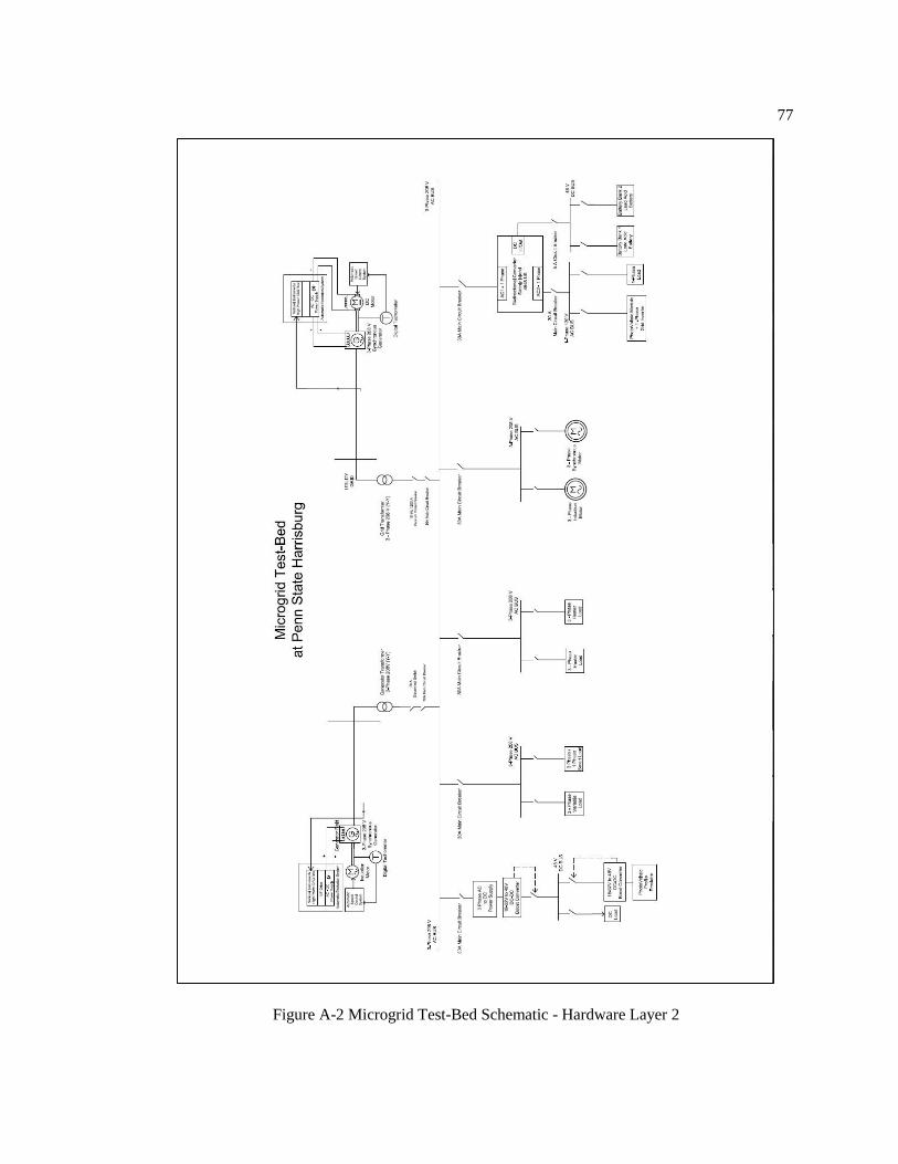
77
Figure A-2 Microgrid Test-Bed Schematic - Hardware Layer 2

78
Figure A-3 Microgrid Test-Bed Schematic - Hardware Layer 3
(Metering and Protection Equipment)

79
Figure A-4 Microgrid Test-Bed Schematic - Hardware Layer 4
(Intelligent Distributed Control)

80
Figure A-5 Microgrid Test-Bed at PSH (Actual Setup)
Figure A-6 Microgrid Control and SCADA Center

81
Appendix B
Microgrid Test-Bed Hardware Specifications
The Hardware specifications about the loads, distributed energy resources, metering and
protection devices, deployed in the Microgrid Test-Bed at PSH are presented in the table B-1.
Table B-1 Hardware Specifications
Sr. No. Hardware Equipment Purpose Specifications
Microgrid Distributed Generation
1 3 phase synchronous
generator
(coupled with 3 phase
induction motor)
Emulation of
gas-turbine/bio-fuel based
generator
3 HP, 208V AC, 60
Hz, 1800 rpm
2 Photovoltaic Emulator Emulation of
solar panel output profiles
Input: 3 phase, 187-
229V, 16A AC, 50-
400 Hz
Output: 0-250V DC,
0-16A DC, 0-4kW
Utility Grid
3 3 phase synchronous
generator
(coupled with dc motor)
Emulation of utility grid 3 phase, 5 kVA,
120/240V AC,
24/12A AC
Energy Storage System
4 Lead Acid Battery Bank For energy storage 48V, 180Ah
(parallel combination
of 4 x 12V, 90Ah
batteries in series )
Power Electronic Interfaces
5 Bi-directional Converter For bi-directional flow of
power from 1-ϕ AC to DC
side and vice-versa
1- ϕ , 4.5kW, 120V
AC, 48V DC
6 AC –DC Rectifier For 3- ϕ AC to 1- ϕ DC
power conversion
Input: 3 phase, 187-
229V, 16A AC, 50-
400 Hz
Output: 0-250V DC,
0-16A DC, 0-4kW
7 DC-DC Boost Converter For voltage conversion from
18V-32V DC to
constant 48 V DC
Input: 18V-32V DC
Output: 48V DC,
5A

82
Static Loads
8 Heater Load (AC
interface)
Residential/ Commercial
heating loads
550W
9 DC Bulb Residential/ Public
lighting system
100W
Adjustable/ Programmable Loads
10 Resistive Load (DC
Interface)
Controllable
Residential/ Commercial
LED lighting system
550W
11 Smart Load
(8 configurations – SLxx)
xx stands for 01 to 08
B stands for balanced
UB stands for unbalanced
R stands for resistive
C stands for capacitive
L stands for inductive
ML stands for motor load
LL stands for lighting load
Emulation of balanced and
unbalanced – resistive,
capacitive, inductive loading
at leading, lagging and zero
power factors
SL01 –
3ϕ-79Ω-R-B
SL02 –
3ϕ-79Ω-R-UB
SL03 –
2ϕ-79Ω-R-UB
SL04 –
79Ω-R-50µF-C-UB
SL05 –
79Ω-R-50mH-L-
50µF-C-UB
SL06 –
1ϕ-370W-115V-
1.7A-60Hz-1725rpm
SL07 –
3ϕ-370W-208V-
0.86A-60Hz-
1725rpm
SL08 –
LL-100W
Dynamic Loads
12 1 Phase Induction Motor Residential/ Commercial ac
rotating machine loads
120W, 120V AC
13 3 Phase Induction Motor Residential/ Commercial ac
rotating machine loads
3- ϕ , 0.25HP, 208-
220V AC, 1.2-1.4A
AC, 1725 rpm
14 3 Phase Synchronous
Motor
Residential/ Commercial ac
rotating machine loads
-
15 DC Motor Residential/ Commercial dc
rotating machine loads
35W (at 48V DC),
rated at 75V, 0.85A,
2500 rpm
Metering Equipment

83
16 Smart Energy Meters For recording power quality
data such as V, I, P, f, and pf
1- ϕ, 2- ϕ, 3-ϕ,
2-wire systems,
3-wire systems,
4-wire systems
Protection-Coordination Equipment
17 Sync-check Relay For performing
synchronization of incoming
line with the utility grid
Bitronics M571 IED
(Intelligent
Electronic Device)
18 Over-Current
Protection Relay
For protection for 3-ϕ
synchronous generator
SEL 421
19 Utility Protection Relay Protection interface for
protection from the utility grid
ABB DPU 2000R
Circuit Breakers
20 Utility-Microgrid
Interconnection Breaker
For the interconnection of
microgrid system with the
utility grid
15kV (max), 1200A
(continuous),
Interrupting time: 3
cycles, Permissible
tripping delay: 2
seconds, Reclosing
time: 0.3 seconds
21 Generator Breaker For connecting the generator
to microgrid 3-ϕ AC phase
3-ϕ, 600V AC, 18A

84
Appendix C
Hourly Load Profiles
A realistic load profile emulation5 is performed for various motor loads, heater loads, and
lighting loads in PC Worx environment. For any particular day, hourly load profiles for critical,
non-critical loads are presented as follows:
1) SL1 - Smart Load 1 (Programmable balanced, unbalanced, R-L-C ac loading system)
Figure C-1 Smart Load 1 Hourly Profile
5 Due to the limitations in several hardware equipment, the critical and the non-critical load
demands, chosen for different test scenarios, were maintained quite low (less than a kilowatt) as compared
to the 12 kilowatts loading capability of the microgrid test-bed, so as to avoid any damages to any equipment.
0
50
100
150
200
250
300
350
1 2 3 4 5 6 7 8 9 10 11 12 13 14 15 16 17 18 19 20 21 22 23 24
Po
we
r C
on
sum
ed
(W
atts
)
Time (Hours)
Smart Load (Variable Loading System)

85
2) SL2 – Smart Load 2 (Adjustable emulated dc residential and public lighting system to
perform demand side management)
Figure C-2 Smart Load 2 Hourly Profile
3) ML1 – Motor Load 1 (Three phase ac induction motor)
Figure C-3 Three Phase Induction Motor Load Hourly Profile
0
100
200
300
400
500
600
1 2 3 4 5 6 7 8 9 10 11 12 13 14 15 16 17 18 19 20 21 22 23 24
Po
we
r C
on
sum
ed
(W
atts
)
Time (Hours)
Smart Load 2
0
10
20
30
40
50
60
1 2 3 4 5 6 7 8 9 10 11 12 13 14 15 16 17 18 19 20 21 22 23 24
Po
we
r C
on
sum
ed
(W
atts
)
Time (Hours)
3 Phase Induction Motor Load

86
4) ML2 – Motor Load 2 (Single phase ac induction motor)
Figure C-4 Single Phase Induction Motor Load Hourly Profile
5) HL2 – Heater Load 2 (DC heater load)
Figure C-5 DC Heater Load Hourly Profile
0
10
20
30
40
50
60
70
80
90
1 2 3 4 5 6 7 8 9 10 11 12 13 14 15 16 17 18 19 20 21 22 23 24
Po
we
r C
on
sum
ed
(W
atts
)
Time (Hours)
1 Phase Induction Motor Load
0
1
2
3
4
5
6
7
8
9
10
1 2 3 4 5 6 7 8 9 10 11 12 13 14 15 16 17 18 19 20 21 22 23 24
Po
we
r C
on
sum
ed
(W
atts
)
Time (Hours)
DC Heater Load

87
6) DC1 – DC Load 1 (DC bulb load)
Figure C-6 DC Bulb Load Hourly Profile
7) DC2 – DC Load 2 (DC motor load)
Figure C-7 DC Motor Load Hourly Profile
0
5
10
15
20
25
1 2 3 4 5 6 7 8 9 10 11 12 13 14 15 16 17 18 19 20 21 22 23 24
Po
we
r C
on
sum
ed
(W
atts
)
Time (Hours)
DC Bulb Load
0
2
4
6
8
10
12
14
16
1 2 3 4 5 6 7 8 9 10 11 12 13 14 15 16 17 18 19 20 21 22 23 24
Po
we
r C
on
sum
ed
(W
atts
)
Time (Hours)
DC Motor Load

88
The total load demand including critical load demand as well as non-critical load demand
is also given as follows:
Figure C-8 Total Critical Load Demand (Hourly)
Figure C-9 Total Non-Critical Load Demand (Hourly)
0
100
200
300
400
500
600
700
1 2 3 4 5 6 7 8 9 10 11 12 13 14 15 16 17 18 19 20 21 22 23 24
Po
we
r C
on
sum
ed
(W
atts
)
Time (Hours)
Total Critical Load Demand
0
50
100
150
200
250
300
350
400
450
1 2 3 4 5 6 7 8 9 10 11 12 13 14 15 16 17 18 19 20 21 22 23 24
Po
we
r C
on
sum
ed
(W
atts
)
Time (Hours)
Total Non-Critical Load Demand

89
Figure C-10 Total Load Demand (Hourly)
0
200
400
600
800
1000
1200
1 2 3 4 5 6 7 8 9 10 11 12 13 14 15 16 17 18 19 20 21 22 23 24
Po
we
r C
on
sum
ed
(W
atts
)
Time (Hours)
Total Load Demand

90
Appendix D
PV Panel Specifications and Hourly Profile
In the microgrid test-bed, a photovoltaic (PV) emulator is used to emulate different PV
profile for different locations, and for different dates. A random PV profile is loaded for a PV panel
specified in table D-1, and the corresponding hourly PV profile is shown in table D-2.
Table D-1 PV Panel Specifications
Sr. No. Parameter Value Unit
1 PV Panel Type cSi -
2 Tref 25 °C
3 Iref 1000 Watt/𝑚2
4 Vmp 24 Volts
5 Imp 5 Amperes
6 Voc 30 Volts
7 Isc 6.3 Amperes
8 β -0.4 %Volts/°C
9 α 0.04 %Amperes/°C
Table D-2 PV Profile (Hourly)
Sr. No. Time of the Day PV Panel Output
1 8 am – 9 am 54 Watts
2 9 am – 10 am 87 Watts
3 10 am – 11 am 90.3 Watts
4 11 am – 12 pm 67.5 Watts
5 12 pm – 1 pm 108 Watts
6 1 pm – 2 pm 98.6 Watts
7 2 pm – 3 pm 93 Watts
8 3 pm – 4 pm 71.3 Watts
9 4 pm – 5 pm 0 Watts
10 5 pm – 6 pm 0 Watts
11 6 pm – 7 pm 0 Watts
12 7 pm – 8 pm 0 Watts

91
Appendix E
PROFINET Data Mapping
1] Load Controller 1 – LC1 (PROFINET Device)
Table E-1 PROFINET Input DATA for Load Controller 1
PND_S1_INPUTS DATA Source
[0] PROFINET Diagnostic MMVC
[1] Smart Load 1 SCADA control MMVC
[2] Smart Load 1 SCADA control MMVC
[3] SCADA control Enable MMVC
[4] SCADA control Grid Breaker Trip MMVC
[180] Smart Load 2 Case 1 DC2
[181] Smart Load 2 Case 2 DC2
[182] Smart Load 2 Case 3 DC2
[183] Smart Load 2 Case 4 DC2
[184] Smart Load 2 Case 5 DC2
[185] Smart Load 2 Case 6 DC2
[186] Smart Load 2 Case 7 DC2
[187] Smart Load Auto/ Manual Select DC2
Table E-2 PROFINET Output DATA for Load Controller 1
PND_S1_OUTPUTS DATA Sink
[0] Smart Load 1 Phase A current MMVC
[1] Smart Load 1 Phase B current MMVC
[2] Smart Load 1 Phase C current MMVC
[3] Smart Load 1 Real Power Consumed MMVC
[4] Smart Load 1 Reactive Power Consumed MMVC
[5] Smart Load 1 Apparent Power Consumed MMVC
[6] Smart Load 1 Power Factor MMVC
[7] Smart Load 1 Rated Power MMVC
[8] Smart Load 1 Connection Status MMVC
[9] Smart Load 2 Current MMVC
[10] Smart Load 2 Real Power Consumed MMVC
[11] Smart Load 2 Reactive Power Consumed MMVC
[12] Smart Load 2 Apparent Power Consumed MMVC
[13] Smart Load 2 Power Factor MMVC

92
[14] Smart Load 2 Rated Power MMVC
[15] Smart Load 2 Connection Status MMVC
2] Load Controller 2 – LC2 (PROFINET Device)
Table E-3 PROFINET Input DATA for Load Controller 2
PND_S1_INPUTS DATA Source
[0] PROFINET Diagnostic MMVC
[1] Heater Load 2 SCADA control MMVC
[2] Motor Load 1 SCADA control MMVC
[3] SCADA control Enable MMVC
[4] SCADA control Grid Breaker Trip MMVC
[180] Smart Load Auto/ Manual Select DC2
Table E-4 PROFINET Output DATA for Load Controller 2
PND_S1_OUTPUTS DATA Sink
[0] Motor Load 1 Phase A current MMVC
[1] Motor Load 1 Phase B current MMVC
[2] Motor Load 1 Phase C current MMVC
[3] Motor Load 1 Real Power Consumed MMVC
[4] Motor Load 1 Reactive Power Consumed MMVC
[5] Motor Load 1 Apparent Power Consumed MMVC
[6] Motor Load 1 Power Factor MMVC
[7] Motor Load 1 Connection Status MMVC
[8] Motor Load 2 Current MMVC
[9] Motor Load 2 Real Power Consumed MMVC
[10] Motor Load 2 Reactive Power Consumed MMVC
[11] Motor Load 2 Apparent Power Consumed MMVC
[12] Motor Load 2 Power Factor MMVC
[13] Motor Load 2 Connection Status MMVC
[14] Motor Load 3 Phase A current MMVC
[15] Motor Load 3 Phase B current MMVC
[16] Motor Load 3 Phase C current MMVC
[17] Motor Load 3 Real Power Consumed MMVC
[18] Motor Load 3 Reactive Power Consumed MMVC
[19] Motor Load 3 Apparent Power Consumed MMVC
[20] Motor Load 3 Power Factor MMVC

93
[21] Motor Load 3 Connection Status MMVC
[22] Heater Load 2 Connection Status MMVC
[23] DC Motor Load Connection Status MMVC
[180] DC Light Bulb Control MMVC
[181] Motor Load 3 Control MMVC
3] DER Controller 1 – DC1 (PROFINET Device)
Table E-5 PROFINET Output DATA for DER Controller 1
PND_S1_OUTPUTS DATA Sink
[0] Microgrid Generator Frequency MMVC
[1] Microgrid Generator Phase A current MMVC
[2] Microgrid Generator Phase B current MMVC
[3] Microgrid Generator Phase C current MMVC
[4] Microgrid Generator Real Power MMVC
[5] Microgrid Generator Power MMVC
[6] Microgrid Generator Apparent Power MMVC
[7] Microgrid Generator Power Factor MMVC
[8] Microgrid Generator Phase A voltage MMVC
[9] Microgrid Generator Phase B voltage MMVC
[10] Microgrid Generator Phase C voltage MMVC
[11] Main 3 Phase Bus Frequency MMVC
[12] Main 3 Phase Bus Phase A current MMVC
[13] Main 3 Phase Bus Phase B current MMVC
[14] Main 3 Phase Bus Phase C current MMVC
[15] Main 3 Phase Bus Real Power MMVC
[16] Main 3 Phase Bus Reactive Power MMVC
[17] Main 3 Phase Bus Apparent Power MMVC
[18] Main 3 Phase Bus Power Factor MMVC
[19] Main 3 Phase Bus Phase A voltage MMVC
[20] Main 3 Phase Bus Phase B voltage MMVC
[21] Main 3 Phase Bus Phase C voltage MMVC
[22] Grid Frequency MMVC
[23] Grid Phase A current MMVC
[24] Grid Phase B current MMVC
[25] Grid Phase C current MMVC
[26] Grid Real Power MMVC
[27] Grid Reactive Power MMVC
[28] Grid Apparent Power MMVC

94
[29] Grid Power Factor MMVC
[30] Grid Phase A voltage MMVC
[31] Grid Phase B voltage MMVC
[32] Grid Phase C voltage MMVC
[33] Grid Breaker Status MMVC
4] DER Controller 2 – DC2 (PROFINET Device)
Table E-6 PROFINET Input DATA for DER Controller 2
PND_S1_INPUTS DATA Source
[0] PROFINET Diagnostic MMVC
[1] DC Light Load SCADA control MMVC
[2] Motor Load 3 SCADA control MMVC
[3] SCADA control Enable MMVC
[4] SCADA control Grid Breaker Trip MMVC
[120] DC Light Bulb Control LC2
[121] Motor Load 3 Control LC2
Table E-7 PROFINET Output DATA for DER Controller 2
PND_S1_OUTPUTS DATA Sink
[0] SMA AC In Frequency MMVC
[1] SMA AC In Phase current MMVC
[2] SMA AC In Real Power MMVC
[3] SMA AC In Power MMVC
[4] SMA AC In Apparent Power MMVC
[5] SMA AC In Power Factor MMVC
[6] SMA Inverter Frequency MMVC
[7] SMA Inverter Phase current MMVC
[8] SMA Inverter Real Power MMVC
[9] SMA Inverter Reactive Power MMVC
[10] SMA Inverter Apparent Power MMVC
[11] SMA Inverter Power Factor MMVC
[12] SCADA control Enable MMVC
[60] Smart Load 2 Case 1 LC1
[61] Smart Load 2 Case 2 LC1
[62] Smart Load 2 Case 3 LC1
[63] Smart Load 2 Case 4 LC1

95
[64] Smart Load 2 Case 5 LC1
[65] Smart Load 2 Case 6 LC1
[66] Smart Load 2 Case 7 LC1
[67] Smart Load Auto/ Manual Select LC1
[120] Smart Load Auto/ Manual Select LC2

96
REFERENCES
[1] Amro M. Farid, Aramazd Muzhikyan , “The Need for Holistic Assessment Methods for
the future electricity grid,” in Gulf Corporation Council CIGRE POWER, Abu Dhabi,
2013, pp. 1-12
[2] S. Massoud Amin, “Smart Grid - Overview, Issues and Opportunities. Advances and
challenges in sensing , modulation, simulation, optimization and control,” European
Journal of Control, vol. 5, no. 5-6, pp. 547-567, 2011.
[3] J. Tough, "Choose Energy," 09-11-2013. [Online]. Available:
https://www.chooseenergy.com/blog/can-traditional-utilities-survive-the-transactive-
energy-solution/. [Accessed: Feb 2015].
[4] U.S.-Canada Power System Outage Task Force, “August 14th , 2003 in the United States
and Canada: Causes and Recommendations,” Final Rep., Aug. 2004
[5] “Report on the Grid Disturbance on 30th July 2012 and Grid Disturbance on 31st July
2012,” Final Rep., Aug. 2012.
[6] Robert H. Lasseter, Paolo Piagi, “Microgrid - a conceptual solution,” in Power Electronics
Specialists Conference (PESC), Aachen, 2004.
[7] Florian Dorfler, John W. Simpson-Porco, Francesco Bullo, “Breaking the Hierarchy:
Distributed Control & Economic Optimality in Microgrids,” 2014. [Online]. Available:
http://arxiv.org/abs/1401.1767 [Accessed: Feb 2015].
[8] Nikos Hatziargyriou, “Centralized and Decentralized Control” in Microgrids –
Architecture and Control, West Sussex, United Kingdom, John Wiley and Sons Ltd., pp.
33-35, 2014.

97
[9] OPC Foundation, "Classic - Data Access," March 2003. [Online]. Available:
https://opcfoundation.org/developer-tools/specifications-classic/data-access/. [Accessed:
June 2014].
[10] Modbus Organization Inc., "Modbus Specifications and Implementation Guides,"
[Online]. Available: http://modbus.org/specs.php. [Accessed: Sept. 2014].
[11] PI North America, "PROFINET: An All-Encompassing Industrial Ethernet Solution,"
Feb 2012. [Online]. Available: http://us.profinet.com/white-paper/profinet-an-all-
encompassing-industrial-ethernet-solution /. [Accessed: Aug. 2014].
[12] Wikipedia, "Industry 4.0," [Online]. Available: http://en.wikipedia.org/wiki/Industry_4.0.
[Accessed: May 2015].
[13] U.S. Department of Energy, Office of Electricity Delivery and Energy Reliability, “The
Smart Grid: An Introduction,” 2008.
[14] European Commission – European SmartGrids Technology Platform, "European
Commision - Research & Innovation - Energy," [Online]. Available:
ec.europa.eu/research/energy/pdf/smartgrids_en.pdf. [Accessed: Sept. 2014].
[15] T. Glenwright, "Introduction to Microgrids," [Online]. Available: http://www.smartgrid-
live.com/wp-content/uploads/2012/12/Introduction-to-Microgrids-by-Tristan-
Glenwright.pdf. [Accessed: Jan 2015].
[16] Robert H. Lasseter, “Smart Distribution – Coupled Microgrids,” Proceedings of the
IEEE, vol. 99, no. 6, pp. 1074-1082, 2011.
[17] Farhad Shahnia, Ruwan P.S. Chandrasena, Sumedha Rajakaruna, Arindam Ghosh,
“Autonomous Operation of Multiple Interconnected Microgrids with Self-healing
Capability,” in Power and Energy Society General Meeting (PES), Vancouver, 2013.

98
[18] Farhad Shahnia, Ruwan P.S. Chandrasena, Sumedha Rajakaruna, Arindam Ghosh,
“Primary Control Level of Parallel Distributed Energy Resources Converters in System of
Multiple Interconnected Autonomous Microgrids within Self-healing Networks,”
Generation, Transmission & Distribution, Institute of Engineering Technology, vol. 8, no.
2, pp. 203-222, 2014.
[19] M. J. Hossain, M. A. Mahmud, H. R. Pota, N. Mithulanathan, R. C. Bansal, “Distributed
Control Scheme to Regulate Power Flow and Minimize Interactions in Multiple
Microgrids,” in Power and Energy Society General meeting, Conference & Exposition,
National Harbor, 2014.
[20] D. Pudjianto, G Strbac, Frank van Overbeeke, A. I. Androutsos, Zigor Larrabe, Joao
Tome Saraiva, “ Investigation of Regulatory, Commercial, Economic and Environmental
Issues in MicroGrids,” in International Conference on Future Power Systems,
Amsterdam, 2005.
[21] Paulo Moises Costa, A. Matos, J. A. Pecas Lopes, “A Regulatory Framework for
Microgeneration and Microgrids,” in Power Tech, Lausanne, 2007.
[22] H. Asano, S. Bando, “Economic Evaluation of Microgrids,” in Power and Energy
General Meeting – Conversion and Delivery of Electrical Energy in the 21st Century,
Pittsburgh, 2008.
[23] Niannian Cai, Ngyuyen Thi Thanh Nga, Joydeep Mitra, “Economic dispatch in multiple
microgrids using Multi-Agent System,” in North American Power Symposium (NAPS),
Champaign, 2012.
[24] E. Ghiani, S. Mocci, F. Pilo, “Optimal Reconfiguration of Distribution Networks
According to the Microgrid Paradigm Optimum Reconfiguration of Microgrids,” in
International Conference on Future Power Systems, Amsterdam, 2005.

99
[25] D. E. Olivares, A. Mehrizi-Sani, A. H. Etemadi, C. A. Canizares, R. Iravani, M. Kazerani,
A. H. Hajimiragha, O. Gomis-Bellmunt, M. Saeedifard, R. Palma-Behnke, G. A. Jimenez-
Estevez and N. D. Hatziargyriou, "Trends in Microgrid Control," IEEE Transactions on
Smart Grid, vol. 5, no. 4, pp. 1905-1919, 2014.
[26] J. Eto, R. Lasseter, B. Schenkman, J. Stevens, D. Klapp, H. Volkommer, E. Linton,
Hector Hurtado, J. Roy, “Overview of CERTS Microgrid Laboratory Test Bed,” in
Integration of Wide-Scale Renewable Resources Into The Power Delivery System,
CIGRE/IEEE PES Joint Symposium, Calgary, 2009.
[27] A. Borghetti, M. Bosetti, C. Bossi, S. Massucco, E. Micolano, A. Morini, “An Energy
Resource Scheduler Implemented in the Automatic Management System of a Microgrid
Test Facility” in International Conference on Clean Electrical Power (ICCEP), Capri,
2007.
[28] Grid Integration Group, “Microgrids at Berkeley lab,” [Online]. Available:
https://building-microgrid.lbl.gov/. [Accessed: Dec. 2014].
[29] Alameda County, “First-of-its-Kind Smart Grid at Santa Rita Jail” [Online]. Available:
http://www.acgov.org/smartgrid.htm. [Accessed: Nov. 2014].
[30] Stan Franklin, Art Graesser, “Is it an Agent, or Just a Program?: A Taxonomy for
Autonomous Agents,” in Intelligent Agents III Agent Theories, Architectures, and
Languages, vol. 1193, pp. 21-35, 1997.
[31] Telecom Italia, "JAVA Agent DEvelopment Framework," [Online]. Available:
http://jade.tilab.com/. [Accessed: Jan 2014].
[32] L. Lee, J. Collis and S. Thompson, "Zeus Agent Toolkit," [Online]. Available:
http://sourceforge.net/projects/zeusagent/. [Accessed: April 2014].

100
[33] The IEEE Foundation for Intelligent Physical Agents, "The Foundation for Intelligent
Physical Agents," [Online]. Available: http://fipa.org/. [Accessed: March 2014].
[34] D. Camacho, R. Aler, C. Castro and J. M. Molina, "Performance evaluation of ZEUS, Jade,
and SkeletonAgent frameworks," in IEEE International Conference on Systems, Man and
Cybernetics, Hammamet, 2002.
[35] Ryozo Kishimoto, “Agent Communication System for Multimedia Communication
Services,” in Proceedings of 5th Annual Joint Conference of the IEEE Computer Societies
(INFOCOM), San Francisco, 1996.
[36] Cedric bonhomme, Christophe Feltus, Djamel Khadraoui, “A Multi-Agent based
Decision Mechanism for Incident Reaction in Telecommunication Network, ” in
IEEE/ACS International Conference on Computer Systems and Applications (AICCSA),
Hammamet, 2010.
[37] Rafael Guedes Alves, Wagner Tanaka Botelho e Maria Gracas Bruno Marietto, Robson
dos Santos Franca, “The YesOrNo System: The Use of Multi-Agent Systems in the Android
Mobile Application Development,” in 8th Iberian Conference on Information Systems and
Technologies, CISTI 2013, Lisboa, pp. 1-6, 2013.
[38] A. L. Kulasekera, K. Hemapala, N. Perera, “A Review on Multi-Agent Systems in
Microgrid Applications,” in IEEE Power and Energy Society Innovative Smart Grid
Technologies - IGST, Kollam, 2011.
[39] J. Hossack, S. D. J. McArthur, J. R. McDonald, J. Stokoe, TCumming, “A Multi-Agent
Approach to Power System Disturbance Diagnosis,” in 5th International Conference on
Power System Management and Control, London, 2002.
[40] S. D. J. McArthur, E. M. Davidson, J. A. Hossack, J. R. McDonald, “Automating Power
System Fault Diagnosis through Multi-Agent System Technology,” in Proceedings of the
37th Annual Hawaii International Conference on System Sciences, Big Island, 2004.

101
[41] L. Cristaldi, A. Monti, R. Ottoboni, F. Ponci, “Multi-Agent Based Power Systems
Monitoring Platform: a Prototype,” in Power Tech Conference Proceedings, Bologna,
2003.
[42] Hai Feng Wang, “Multi-agent Coordination for the Secondary Voltage Control in Power
System Contingencies,” Generation, Transmission & Distribution, Institute of
Engineering Technology, vol. 148, no. 1, pp. 61-66, 2001.
[43] Ramesh Rajesh, Dhiwakar Purusothaman S. R. R., Karan K. Bajaj, Vineeth
Vijayaraghavan, “Multi-Agent System Framework for Rural Indian Microgrids,” in IEEE
Conference on Clean Energy and Technology, CEAT 2013, Lankgkawi, pp. 76-81, 2013.
[44] Niannian Cai, Xufeng Xu, Joydeep Mitra, “A Hierarchical Multi-agent Control Scheme
for a Black Start-Capable Microgrid,” in IEEE Power and Energy Society General
Meeting, San Diego, pp. 1-7, 2011.
[45] Teymoor Ghanbari, Ebrahim Farjah, “A Multi agent-Based Fault-Current Limiting
Scheme for the Microgrids,” IEEE Transactions on Power Delivery, vol. 29, no. 2, pp.
525-533, 2013.
[46] Chong Shao, Chen Xu, Shan He, Xiangning Lin, Xianshan Li, “Operation of Microgrid
Reconfiguration based on MAS (Multi-Agent System),” in TENCON – 2013 IEEE
Region 10 Conference, Xi’an, 2013.
[47] Mark E. Collins, Richard W. Silversides, Timothy C. Green, “Multi-Agent System
Control and Coordination of an Electrical Network,” in 47th International Universities
Power Engineering Conference (UPEC), London, 2012.
[48] Saifur Rahman, Manisa Pipattanasomporn, Yonael Teklu, “Intelligent Distributed
Autonomous Power Systems (IDAPS),” in IEEE Power Engineering Society General
Meeting, Tampa, 2007.

102
[49] Aris L. Dimeas, Nikos D. Hatziargyriou, “Operation of a Multiagent System for
Microgrid Control,” IEEE Transactions on Power Systems, vol. 20, no. 3, pp. 1447-1455,
2005.
[50] H. N. Aung, A. M. Khambadkone, D. Srinivasan, T. Logenthiran, “Agent-based
Intelligent Control for Real-Time Operation of a Microgrid,” in 2010 Joint International
Conference on Power Electronics, Drives, and Energy Systems & 2010 Power India, New
Delhi, 2010.
[51] Rahul Mehta, Bharat Menon, Dipti Srinivasan, Sanjib Kumar Panda, Akshay Kumar
Rathore, “Market Based Multi-Agent Control of Microgrid,” in IEEE 9th International
Conference on Intelligent Sensors, Sensor Networks and Information Processing
(ISSNIP), Singapore, 2014.
[52] T. Logenthiran, Dipti Srinivasan, David Wong, “Multi-agent Coordination for DER in
Microgrid,” in IEEE Conference on Sustainable Energy Technologies (ICSET),
Singapore, 2008.
[53] Xianyong Feng, “Dynamic Balancing for Low Inertia Power Systems,” in IEEE Power
and Energy Society General Meeting, Vancouver, 2013.
[54] Z. Li, C. Zang, P. Zeng, H. Yu, H. Li and S. Li, "Analysis of Multi-Agent-Based
Adaptive Droop-Controlled AC Microgrids with PSCAD: Modeling and Simulation,"
Journal of Power Electronics, vol. 15, no. 2, pp. 455-468, 2015.
[55] Leonardo L. do Nascimento, Jacqueline G. Rolim, “Multi-agent System for Adaptive
Protection in Microgrids,” in IEEE Power and Energy Society Conference on Innovative
Smart Grid technologies Latin America (ISGT LA), Sao Paulo, 2013.
[56] Stephanus A. Ananda, Jyh-Cherng Gu, “Multi-Agent Based Protection on Highly
Dominated Distributed Energy Resources,” Energy and Power Engineering, vol. 5, no.
4B, pp. 927-931, 2013.

103
[57] Open SCADA, "Utgard," [Online]. Available: http://openscada.org/projects/utgard/.
[Accessed: Oct. 2014].
[58] J. Li , J. Su, X. Yang and T. Zhao, "Study on microgrid operation control and black
start," in 4th International Conference on Electric Utility Deregulation and Restructuring
and Power Technologies (DRPT), Weihai, 2011.
[59] A. Otto and K. Hellmann, "IEC 61131: A General Overview and Emerging Trends," IEEE
Industrial Electronics Magazine, vol. 3, no. 4, pp. 27-31, 2009.