Muhammad Ahsan Kabir - Chalmers
67
Modelling of Converters Dominated AC Microgrid with Communication System Master’s thesis in Electric Power Engineering Muhammad Ahsan Kabir Department of Electrical Engineering CHALMERS UNIVERSITY OF TECHNOLOGY Gothenburg, Sweden 2019
Transcript of Muhammad Ahsan Kabir - Chalmers

Modelling of Converters Dominated AC Microgrid withCommunication System
Master’s thesis in Electric Power Engineering
Muhammad Ahsan Kabir
Department of Electrical EngineeringCHALMERS UNIVERSITY OF TECHNOLOGYGothenburg, Sweden 2019


Master’s thesis 2019
Modelling of Converters Dominated ACMicrogrid with Communication System
MUHAMMAD AHSAN KABIR
Department of Electrical EngineeringDivision of Electric Power Engineering
Chalmers University of TechnologyGothenburg, Sweden 2019

Modelling of Converters Dominated AC Microgrids with Communication System
MUHAMMAD AHSAN KABIR
Supervisor: Dr. Gustavo Pinares, Chalmers University of Technology.Examiner: Prof. Massimo Bongiorno, Chalmers University of Technology.
Master’s Thesis 2019Department of Electrical EngineeringDivision of Electric Power EngineeringChalmers University of TechnologySE-412 96 GothenburgTelephone +46 31 772 1000
iii

AbstractDue to the ever increasing demand of electricity to fulfill our energy requirementsand achieving CO2 reduction goals at the same time, microgrids with renewableenergy sources are playing vital role. A microgrid is a small scale power systemwith its own energy resources with the ability to supply the consumers even in caseof contingencies at the main grid. Modern microgrids integrate renewable sources,which are typically interfaced through power electronic converters. These convertersare coordinated through a communication system.
For this thesis, a microgrid model with a solar PV unit and a battery energy storagesystem(BESS) has been implemented with a centralized controller using PSCAD.Local controllers for both solar PV unit and battery unit have been designed for thecase of islanded mode operation. There is also a secondary controller, called centralcontroller, which regulates the battery power and solar power in case of islandedmode to keep balance between the generation and load. For controlling the powerin the grid connected mode, utility grid power controller has been implemented asper the requirement of the microgrid to be operated in power control mode whenoperating in grid connected mode. In islanded mode, battery controller is the onewhich controls the voltages of the microgrids and, thus, system works in voltagecontrol mode. Finally the impacts of communication delay on the converters coor-dination, and eventually the system behaviour, have been investigated.
Maximum rating of solar PV unit, battery unit and load are 100 kW, 210 Ahr and68 kW respectively while system operates at nominal voltage and frequency valuesof 400 V and 50 Hz respectively. It has been found that communication delays intransition from grid connected mode to islanded mode can cause instability if theyexceed certain value. Moreover, it has been found that system is able to survivewith long delays between the controllers if the generation is close to the demand.Finally the comparison of the power outputs from the converters has been presentedwith different communication time delays and operating parameters.
Keywords: Microgrid, Power Electronic Converters, Wireless Communication,Battery Energy Storage System, Photovoltaic Array
iv


AcknowledgementsFirst and foremost, I would like to express my deepest gratitude to my supervisor,Dr. Gustavo Pinares, for his guidance, advice and support during my thesis workat Chalmers University of Technology. Without his valuable technical support thiswork would have not been possible. Also, I would appreciate the support providedby my nice examiner, Prof. Massimo Bongiorno, which has been of vital importanceto complete this thesis in time.
The assistance provided by my friends in very critical times has also been a greatsource of encouragement. My special gratitude goes to Swedish Institute(SI) whichis the sponsor of my studies and the driving force for me to complete my studiesfrom a worldly renowned Charmers University of Technology.
Finally, I am particularly grateful to my family for their support and encouragementthroughout my studies. Words cannot express how grateful I am to you, especiallymy mother, for all of the sacrifices that you have made on my behalf.
Muhammad Ahsan Kabir, Gothenburg, February 2019
vi


Contents
List of Figures xi
List of Tables xiii
1 Introduction 11.1 Background and Motivation . . . . . . . . . . . . . . . . . . . . . . . 11.2 Problem Statement and Aim . . . . . . . . . . . . . . . . . . . . . . . 11.3 Methodology . . . . . . . . . . . . . . . . . . . . . . . . . . . . . . . 21.4 Scope . . . . . . . . . . . . . . . . . . . . . . . . . . . . . . . . . . . 21.5 Contribution . . . . . . . . . . . . . . . . . . . . . . . . . . . . . . . . 21.6 Thesis Outline . . . . . . . . . . . . . . . . . . . . . . . . . . . . . . . 2
2 Importance of Microgrid and its Components 42.1 Energy Sources in Microgrids . . . . . . . . . . . . . . . . . . . . . . 42.2 Importance of micro-grids in modern world . . . . . . . . . . . . . . . 5
2.2.1 Economical Benefit . . . . . . . . . . . . . . . . . . . . . . . . 52.2.2 Reduction in Carbon Footprints . . . . . . . . . . . . . . . . . 52.2.3 Security of Supply . . . . . . . . . . . . . . . . . . . . . . . . 5
2.3 Microgrids’ Operating Modes . . . . . . . . . . . . . . . . . . . . . . 52.3.1 Grid Connected Mode . . . . . . . . . . . . . . . . . . . . . . 52.3.2 Islanded Mode . . . . . . . . . . . . . . . . . . . . . . . . . . 6
2.4 Micro-grids components . . . . . . . . . . . . . . . . . . . . . . . . . 62.4.1 Connection Terminal . . . . . . . . . . . . . . . . . . . . . . . 62.4.2 Battery Energy Storage System(BESS) . . . . . . . . . . . . . 62.4.3 Power Electronic Converters . . . . . . . . . . . . . . . . . . . 72.4.4 Central Controller . . . . . . . . . . . . . . . . . . . . . . . . 72.4.5 Protection System . . . . . . . . . . . . . . . . . . . . . . . . 7
2.5 Types of Loads . . . . . . . . . . . . . . . . . . . . . . . . . . . . . . 82.5.1 Critical Loads . . . . . . . . . . . . . . . . . . . . . . . . . . . 82.5.2 Non-Critical Load . . . . . . . . . . . . . . . . . . . . . . . . . 8
2.6 Challenges in microgrids . . . . . . . . . . . . . . . . . . . . . . . . . 82.6.1 Integration of Renewable Sources . . . . . . . . . . . . . . . . 82.6.2 Variation of RES . . . . . . . . . . . . . . . . . . . . . . . . . 82.6.3 Transition to Isolated Mode . . . . . . . . . . . . . . . . . . . 8
3 Modelling of Micro-grid Components 103.1 Power Electronic Converters . . . . . . . . . . . . . . . . . . . . . . . 10
viii

Contents
3.2 Inverters’ Modes of Operation . . . . . . . . . . . . . . . . . . . . . . 113.3 Interfacing Converter Topologies . . . . . . . . . . . . . . . . . . . . . 11
3.3.1 Single-Stage Converter Topology . . . . . . . . . . . . . . . . 113.3.2 Double-Stage Converter Topology . . . . . . . . . . . . . . . . 123.3.3 Multi-Stage Converter Topology . . . . . . . . . . . . . . . . . 13
3.4 Solar PV . . . . . . . . . . . . . . . . . . . . . . . . . . . . . . . . . . 133.4.1 Solar PV Components . . . . . . . . . . . . . . . . . . . . . . 133.4.2 Equivalent Circuit of a Solar Cell . . . . . . . . . . . . . . . . 143.4.3 V-I Characteristics of Solar PV . . . . . . . . . . . . . . . . . 153.4.4 Arrangement of Modules . . . . . . . . . . . . . . . . . . . . . 153.4.5 Power-Voltage Characteristics of Solar PV . . . . . . . . . . . 16
3.5 Selection of the Battery . . . . . . . . . . . . . . . . . . . . . . . . . 173.5.1 Sizing of the Battery . . . . . . . . . . . . . . . . . . . . . . . 183.5.2 Nominal Discharge Current . . . . . . . . . . . . . . . . . . . 18
4 Control Techniques in the Micro-grid 204.1 Different Reference Frames for VSI Control . . . . . . . . . . . . . . . 20
4.1.1 abc Reference Frame . . . . . . . . . . . . . . . . . . . . . . . 204.1.2 Stationary Reference Frame . . . . . . . . . . . . . . . . . . . 204.1.3 Synchronous Reference Frame . . . . . . . . . . . . . . . . . . 21
4.2 Current Controller Design . . . . . . . . . . . . . . . . . . . . . . . . 214.2.1 PI Control Loop . . . . . . . . . . . . . . . . . . . . . . . . . 214.2.2 Cross Coupling and Feed-forward Terms . . . . . . . . . . . . 224.2.3 Phase Locked Loop(PLL) . . . . . . . . . . . . . . . . . . . . 22
4.3 DC Voltage Regulator . . . . . . . . . . . . . . . . . . . . . . . . . . 234.4 Grid Transition Logic . . . . . . . . . . . . . . . . . . . . . . . . . . . 234.5 Controller for Solar PV . . . . . . . . . . . . . . . . . . . . . . . . . . 24
4.5.1 Control Strategy in the Grid Connected Mode . . . . . . . . . 244.5.2 Control Strategy in the Islanded Mode . . . . . . . . . . . . . 25
4.6 Battery Controller . . . . . . . . . . . . . . . . . . . . . . . . . . . . 264.6.1 Controller for grid connected mode . . . . . . . . . . . . . . . 264.6.2 Controller for islanded mode . . . . . . . . . . . . . . . . . . . 264.6.3 Frequency Control in the Islanded Mode . . . . . . . . . . . . 27
4.7 Utility Grid Power Controller . . . . . . . . . . . . . . . . . . . . . . 27
5 Types of Communication Systems in the Microgrid 285.1 Types of Communication in Microgrid . . . . . . . . . . . . . . . . . 285.2 Types of Communication Architectures . . . . . . . . . . . . . . . . . 29
5.2.1 Centralized Control Architecture . . . . . . . . . . . . . . . . 295.2.2 Decentralized Control Architecture . . . . . . . . . . . . . . . 30
5.3 Communication Protocols in Microgrid . . . . . . . . . . . . . . . . . 30
6 Simulation and Results 326.1 System Description . . . . . . . . . . . . . . . . . . . . . . . . . . . . 326.2 Base Case Simulations . . . . . . . . . . . . . . . . . . . . . . . . . . 346.3 Battery power regulation with excess power from Solar PV . . . . . . 34
ix

Contents
6.3.1 Constant load with variation in solar radiation and power pro-duction . . . . . . . . . . . . . . . . . . . . . . . . . . . . . . 34
6.3.2 Constant irradiance with variation in load . . . . . . . . . . . 356.4 Transition from Grid-connected to Islanded Mode . . . . . . . . . . . 37
6.4.1 Large Generation of Solar with Constant Load . . . . . . . . . 376.5 Simulations considering communication delays . . . . . . . . . . . . . 38
6.5.1 Transition from Grid Connected Mode to Isolated Mode . . . 386.5.1.1 Analysis . . . . . . . . . . . . . . . . . . . . . . . . . 40
6.5.2 Delays in the Battery Secondary Power Controller . . . . . . . 406.5.3 Delays in the Solar PV Regulation . . . . . . . . . . . . . . . 42
6.6 Delays in communication in islanded mode . . . . . . . . . . . . . . . 446.6.1 Constant Load with Variation in Irradiance . . . . . . . . . . 446.6.2 Constant Irradiance with Variation in Load . . . . . . . . . . 45
7 Conclusion and Future Work 487.1 Conclusion . . . . . . . . . . . . . . . . . . . . . . . . . . . . . . . . . 487.2 Future Work . . . . . . . . . . . . . . . . . . . . . . . . . . . . . . . . 49
Bibliography 50
x

List of Figures
2.1 Renewable Electricity Growth 1994-2022[3] . . . . . . . . . . . . . . . 42.2 A Typical Microgrid . . . . . . . . . . . . . . . . . . . . . . . . . . . 62.3 Block Diagram of Switching Converters . . . . . . . . . . . . . . . . . 7
3.1 Voltage Source Inverter . . . . . . . . . . . . . . . . . . . . . . . . . . 113.2 Single Stage DC-AC Interfacing Converter . . . . . . . . . . . . . . . 123.3 Double Stage DC-DC-AC Interfacing Converter . . . . . . . . . . . . 123.4 Double Stage AC-DC-AC Interfacing Converter . . . . . . . . . . . . 133.5 Multi Stage DC-AC Interfacing Converter . . . . . . . . . . . . . . . 133.6 Solar PV Components . . . . . . . . . . . . . . . . . . . . . . . . . . 143.7 Equivalent Electrical Circuit of a Solar Cell . . . . . . . . . . . . . . 143.8 VI Characteristic of the Solar PV . . . . . . . . . . . . . . . . . . . . 153.9 Solar output for the configuration in Table 3.1 . . . . . . . . . . . . . 163.10 Setup for plotting the Power-Voltage curves . . . . . . . . . . . . . . 163.11 PV curves at different radiation intensities . . . . . . . . . . . . . . . 173.12 Equivalent Electrical Model of the Battery . . . . . . . . . . . . . . . 17
4.1 Block diagram of a current controller . . . . . . . . . . . . . . . . . . 214.2 Block Diagram of a PI Controller . . . . . . . . . . . . . . . . . . . . 224.3 Block Diagram of PLL . . . . . . . . . . . . . . . . . . . . . . . . . . 234.4 Block Diagram of DC Voltage Regulator . . . . . . . . . . . . . . . . 234.5 Transition Logic of Microgrid . . . . . . . . . . . . . . . . . . . . . . 244.6 Solar PV regulator for grid connected mode . . . . . . . . . . . . . . 244.7 Solar PV regulator for islanded mode . . . . . . . . . . . . . . . . . . 254.8 Secondary controller for islanded mode . . . . . . . . . . . . . . . . . 254.9 Battery controller in grid-connected mode . . . . . . . . . . . . . . . 264.10 Battery voltage controller in islanded mode . . . . . . . . . . . . . . . 264.11 Islanded Mode Frequency Controller . . . . . . . . . . . . . . . . . . 274.12 Utility Grid Power Controller . . . . . . . . . . . . . . . . . . . . . . 27
5.1 Centralized Communication Architecture . . . . . . . . . . . . . . . . 305.2 Centralized Communication Architecture . . . . . . . . . . . . . . . . 30
6.1 Description of the microgrid . . . . . . . . . . . . . . . . . . . . . . . 326.2 Converter schematic with electrical components . . . . . . . . . . . . 336.3 Battery controller in grid-connected mode . . . . . . . . . . . . . . . 346.4 Battery Inverter Power Output . . . . . . . . . . . . . . . . . . . . . 35
xi
List of Figures
6.5 Solar PV Output . . . . . . . . . . . . . . . . . . . . . . . . . . . . . 356.6 Battery Inverter Power Output . . . . . . . . . . . . . . . . . . . . . 366.7 Solar PV Output . . . . . . . . . . . . . . . . . . . . . . . . . . . . . 366.8 Solar power @ Irradiance = 1000W/m2 . . . . . . . . . . . . . . . . . 386.9 Battery power . . . . . . . . . . . . . . . . . . . . . . . . . . . . . . . 386.10 Delays in the transfer of voltage references . . . . . . . . . . . . . . . 396.11 Battery power comparison with different time delays . . . . . . . . . 396.12 Solar power comparison with different time delays . . . . . . . . . . . 406.13 Delay in battery power input signal . . . . . . . . . . . . . . . . . . . 416.14 Battery power output for different time delays . . . . . . . . . . . . . 416.15 Solar power output for different time delays . . . . . . . . . . . . . . 426.16 Delay introduced int he solar PV power regulator . . . . . . . . . . . 436.17 Battery power output for different delays . . . . . . . . . . . . . . . . 436.18 Solar power output for different delays . . . . . . . . . . . . . . . . . 436.19 Battery power output for different delays . . . . . . . . . . . . . . . . 446.20 Battery power output for different delays . . . . . . . . . . . . . . . . 456.21 Solar power output for different delays . . . . . . . . . . . . . . . . . 456.22 Delay introduced int he solar PV power regulator . . . . . . . . . . . 466.23 Battery power output for different delays . . . . . . . . . . . . . . . . 466.24 Solar power output for different delays . . . . . . . . . . . . . . . . . 47
xii
List of Tables
3.1 PV Parameters for the Modelling . . . . . . . . . . . . . . . . . . . . 16
5.1 Comparison of various wireless technologies[28],[29] . . . . . . . . . . 29
6.1 Microgrid Components . . . . . . . . . . . . . . . . . . . . . . . . . . 326.2 Transformer Specifications . . . . . . . . . . . . . . . . . . . . . . . . 336.3 Cables Specifications . . . . . . . . . . . . . . . . . . . . . . . . . . . 336.4 L,R and C Values . . . . . . . . . . . . . . . . . . . . . . . . . . . . . 336.5 Steady-state power values before and after the transition . . . . . . . 376.6 Radiation and load values for the cases . . . . . . . . . . . . . . . . . 406.7 Analysis of the case under different conditions . . . . . . . . . . . . . 426.8 Analysis of the case under different conditions . . . . . . . . . . . . . 44
xiii

1Introduction
1.1 Background and MotivationMicro-grids can be defined as small scale power system that are able to supply powerto electricity consumers even if disconnected from the main system. It is a conceptwhere distributed energy resources are preferred over the centralized conventionalpower systems. Due to high power demand in modern world and the goal of de-creasing CO2 emissions worldwide, renewable energy sources (RES) are increasinglygaining attention as an alternative to reach the CO2 emissions’ goal. However, alongwith the benefits, RES bring in also challenges, being the most recognized variablepower sources. Typically, in a micro-grid, this is overcome through coordination be-tween different resources such as energy storage and other flexible energy sources[1].
Distributed energy resources includes energy production from sources such as solarcells, fuel cells, wind power, energy storage devices (e.g. batteries), small CHP anddiesel generators. In this regard, converters have a major role when we talk aboutthese small scale power systems since they allow the connection of dc-voltage basedenergy sources to 50 Hz or 60 Hz ac systems and also are used to convert any otherfrequency value to nominal one e.g. in case of wind[2].
As mentioned above, one shortcoming of RES is their variability. One way to over-come this problem is through the coordination of the resources in the microgrid,which involves the need for communication. Due to the variability of RES, it isessential to have a communication system to coordinate the resources in a microgridsuch that production and consumption is in balance. A good communication systemin the micro-grid facilitates avoiding interruptions in the supply of power even if onesource is not producing enough energy to meet the requirement.
1.2 Problem Statement and AimThe objective of this thesis work is to study the impact on the dynamic performanceof microgrid when a number converters are operating and coordinating togetherthrough a communication system in the microgrid. In this regard, it is importantto consider the impact of events such as delays in the communication on the systemperformance.
1

1. Introduction
1.3 MethodologyTo analyze the dynamic behaviour of a power electronic converters dominated mi-crogrid, a model of the AC microgrid with solar PV and Battery Energy StorageSystem (BESS) as RES will be implemented. The behaviour of the microgrid forboth grid connected and isolated modes will be studied. The model will be imple-mented in an Electromagnetic Transient (EMT)/PSCAD program and the impactof communication delays between the devices in the grid will be investigated withthe help of implemented model. Findings of the work and recommendations for thefuture work will be presented in the thesis.
1.4 ScopeA microgrid consists of different energy source. However, for the thesis work onlysolar PV and battery will be considered. Modelling of the battery unit and solarPV unit will be described along with the inverter topologies for the thesis and theconverters are modelled as average models only. Control strategies of the local con-trollers of solar PV unit and battery unit will be implemented. Central controller forthe regulation of battery power will be designed as a master controller to commandthe local controllers. The design of communication network is beyond the scope ofthe thesis and delays are only considered in this thesis. Also protection system of amicrogrid is not included in the scope of this thesis. The study deals with the fastdynamics thus optimal operating points are not considered in the thesis.
1.5 ContributionA microgrid model has been implemented with only solar PV and battery as energysources. Control strategies for islanded operation mode have been implemented andsystem behaviour has been analyzed. After modelling the microgrid, communicationdelays have been introduced for different cases e.g. delay in transition feedbackand the delay in solar PV controller etc. The behaviour of the system has beeninvestigated due to these delays. Delays with different operating parameters e.gsolar irradiance and connected load etc. has been observed and a comparativeanalysis has been presented. The thesis also shows the point where the system ismost likely to able to survive even if there is some disturbance in communicationdelay or operating parameters.
1.6 Thesis OutlineChapters are summarized below excluding the introduction chapter.
2

1. Introduction
• Chapter 2 describes the importance of microgrid alongwith its componentsand challenges.
• Chapter 3 provides the modelling of components used to model the system forthe thesis work.
• Chapter 4 shows the controllers implementation which have been designed tomodel the microgrid.
• Chapter 5 is related to communication systems which are used in the micro-grids in modern days.
• Chapter 6 presents the simulation results of the work and performs the corre-sponding analysis.
• Chapter 7 presents concluding remarks for the thesis and also suggestions forthe future work.
3

2Importance of Microgrid and its
Components
2.1 Energy Sources in MicrogridsA microgrid refers to the network of distributed energy sources and loads that canbe operated in a coordinated way. It can integrate both conventional and renewableenergy sources. Due to the goals of decreasing CO2 emissions worldwide, renewableenergy sources are gaining attention as an alternative to conventional sources forachieving the goal of reduction in carbon footprints while fulfilling our energy de-mands. Typical sources which are included in the micro grid are solar PVs, windturbines, hydrogen fuel cells, small hydro, small combined heat and power (CHP)plant.
Apart from these energy generating sources, energy storage plays a key role in thesuccessful operation of a microgrid. Batteries with proper control of power can beused to store energy when there is excess of energy, e.g power produced by a solarPV. When there is a deficit of power from renewable sources, this stored energy canbe utilized to provide the uninterrupted power to the consumers. Other energy stor-age devices that can be mentioned are super-capacitors and flywheels, for example.
Figure 2.1: Renewable Electricity Growth 1994-2022[3]
In Figure 2.1, we can see a drastic increase of power production from renewable
4

2. Importance of Microgrid and its Components
energy sources in the last few decades. This trend is expected to continue in nearfuture with solar PV as the most dominant one renewable energy source.
2.2 Importance of micro-grids in modern worldFew of the most important benefits coming from microgrids are described below.
2.2.1 Economical BenefitFor transmitting power to long distances, we need high voltage transmission lines,transformers and other high voltage equipment. Such investments can be delayedif we build a microgrid near the area of demand. Moreover, the looses due to thetransmission over long distances are also avoided[4].
2.2.2 Reduction in Carbon FootprintsThe world is going towards resources that are environment friendly to achieve itstarget of CO2 reduction. Microgrids have most of this energy production comingform RES especially from wind, solar, small hydro depending upon the region along-with the energy storage. Moreover, recent developments of control strategies allowsthe integration of increasing amount of RES. So, CO2 emissions are reduced withalmost uninterruptible power supply all the time and thus also improves local energydelivery[5].
2.2.3 Security of SupplyA microgrid has the ability of operating even when not connected to the utilitygrid. Thus, in case of blackouts at the utility grid, the microgrid is still able tosupply electricity to the consumer. Thus the stability of microgrid, even in thecase of utility grid failure, is maintained which keeps voltage and frequency withinallowable operating limits[6].
2.3 Microgrids’ Operating ModesMicrogrid operation can be divided into two modes, described as follows.
2.3.1 Grid Connected ModeIn this mode of operation, utility grid is connected with he microgrid. When con-nected with he grid, microgrid usually draws power from the main grid but it canalso deliver power to the utility grid if DER’s are generating large power comparedto the load. Bidirectional power flow is necessary for this mode.
5

2. Importance of Microgrid and its Components
2.3.2 Islanded ModeIn this mode, the microgrid is not connected with the utility grid and, hence, worksindependently to have its own generation to balance the load requirement. DERsmay provide enough energy in this mode or stored energy can also be used if thereis less power production from micro sources.
2.4 Micro-grids componentsA typical microgrid is shown in 2.2. Due to particular technical requirements, themicrogrid consists of the following major elements.
Figure 2.2: A Typical Microgrid
2.4.1 Connection TerminalMicro-grid is designed in such a way that it has the option to connect to or disconnectfrom the utility grid. This interface can be achieved with a three phase electro-mechanical breaker, for example.
2.4.2 Battery Energy Storage System(BESS)For balancing generation and demand when having only variable renewable energysources in the microgrid, we need energy storage. Energy storage devices with propercontrol act immediately to balance the demand with energy supply and can evenhelp decrease the loading of the utility network during peak load hours. LithiumIon batteries are dominating the market for storage purposes in modern microgrid.
6
2. Importance of Microgrid and its Components
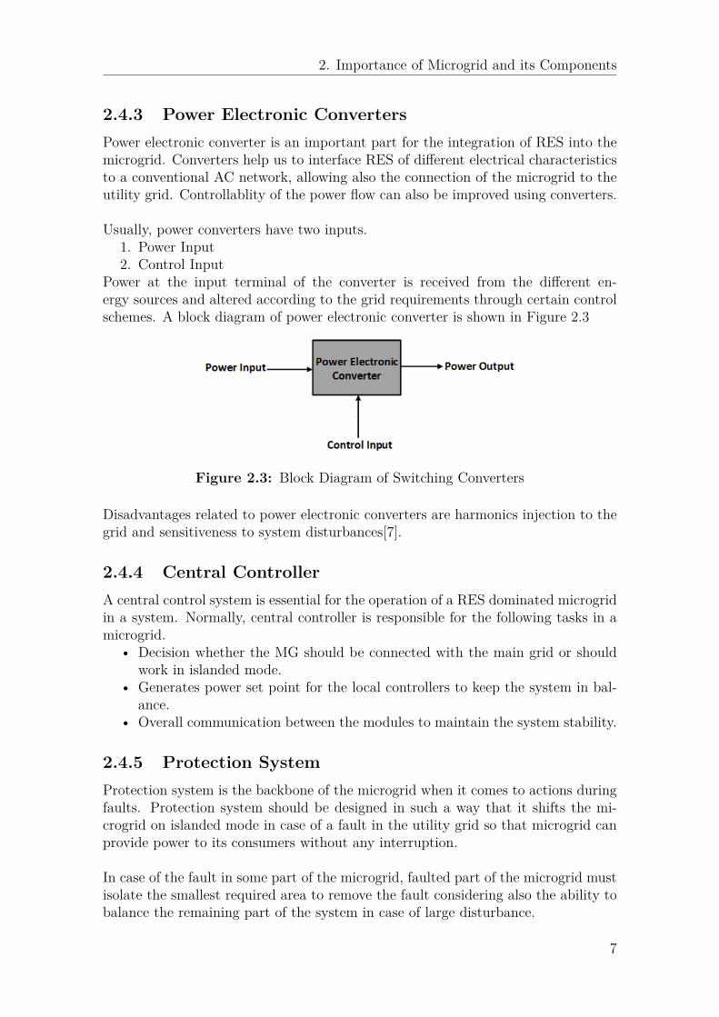
2.4.3 Power Electronic ConvertersPower electronic converter is an important part for the integration of RES into themicrogrid. Converters help us to interface RES of different electrical characteristicsto a conventional AC network, allowing also the connection of the microgrid to theutility grid. Controllablity of the power flow can also be improved using converters.
Usually, power converters have two inputs.1. Power Input2. Control Input
Power at the input terminal of the converter is received from the different en-ergy sources and altered according to the grid requirements through certain controlschemes. A block diagram of power electronic converter is shown in Figure 2.3
Figure 2.3: Block Diagram of Switching Converters
Disadvantages related to power electronic converters are harmonics injection to thegrid and sensitiveness to system disturbances[7].
2.4.4 Central ControllerA central control system is essential for the operation of a RES dominated microgridin a system. Normally, central controller is responsible for the following tasks in amicrogrid.
• Decision whether the MG should be connected with the main grid or shouldwork in islanded mode.
• Generates power set point for the local controllers to keep the system in bal-ance.
• Overall communication between the modules to maintain the system stability.
2.4.5 Protection SystemProtection system is the backbone of the microgrid when it comes to actions duringfaults. Protection system should be designed in such a way that it shifts the mi-crogrid on islanded mode in case of a fault in the utility grid so that microgrid canprovide power to its consumers without any interruption.
In case of the fault in some part of the microgrid, faulted part of the microgrid mustisolate the smallest required area to remove the fault considering also the ability tobalance the remaining part of the system in case of large disturbance.
7

2. Importance of Microgrid and its Components
2.5 Types of LoadsLoads in a microgrids can be categorized as below.
2.5.1 Critical LoadsThis type of load needs good quality power without interruptions. The local energysources and energy storage equipment must ensure the reliable and uninterruptedsupply of power to these loads. Examples of these kinds of loads include hospitalsand banks.
2.5.2 Non-Critical LoadThe priority of such loads is lower compared to critical loads. Supply of these loadscan be disconnected when there is need to stabilize the system after a disturbance.Examples may include charging station and street lightning etc.
2.6 Challenges in microgridsApart from benefits microgrid has also some challenges to overcome. Some of whichare listed next.
2.6.1 Integration of Renewable SourcesMicrogrid enables high penetration of renewables which is also sometimes a chal-lenge for the overall system. The high amount of renewables with no rotationalmasses reduces the rotational inertia of the system. This reduction in inertia makesthe overall system more vulnerable to disturbances and frequency deviations. Oneway to handle this is the implementation of synthetic inertia[8].
2.6.2 Variation of RESRenewable energy production is stochastic in nature and can vary abruptly duringdifferent hours. It may produce more energy than needed or it may suddenly dropdown to values lower than the electricity demand. Therefore, storage and coordi-nated control is needed if more renewable energy sources are added to a power systemto avoid the power unbalance, which may result in a system failure in the worst case.
2.6.3 Transition to Isolated ModeOne of the challenges is the control of power and voltages thorough the microgridduring the transition from grid connected to isolated mode. So, control strategiesneed to be implemented for a safe transition.
8

2. Importance of Microgrid and its Components
Mismatches between load and generation may arise when transition happens fromgrid connected to isolated mode. Proper and fast control actions must avoid anykind of unnecessary load shedding during the transition.
9
3Modelling of Micro-grid
Components
3.1 Power Electronic ConvertersConverter is a generic term associated with a power electronic device that convertselectric power from one characteristic to another. Examples are DC-DC convert-ers, inverters and rectifiers. Inverters are used when we need conversion of powerfrom DC to AC and rectifiers are required when conversion is needed from AC to DC.
The output power from renewable energy sources and energy storage system is eitherDC or AC with non fundamental frequency so converters are needed to integratethese sources with the grid and to make this power usable for commercial and res-idential appliances. There are two types of three phase inverters available for thisconversion process which are current source inverters (CSI) and voltage source in-verters (VSI). The key difference between these two is the energy storage methodon the DC side.
Semiconductor devices are the fundamental components of a converter. For powerapplications, inverters are preferably designed with insulated-gate bipolar transis-tors (IGBTs) with anti parallel diodes to make the flow of current possible in bothdirection. The reason for prioritizing IGBT is their high voltage ratings and lowerpower losses[9].
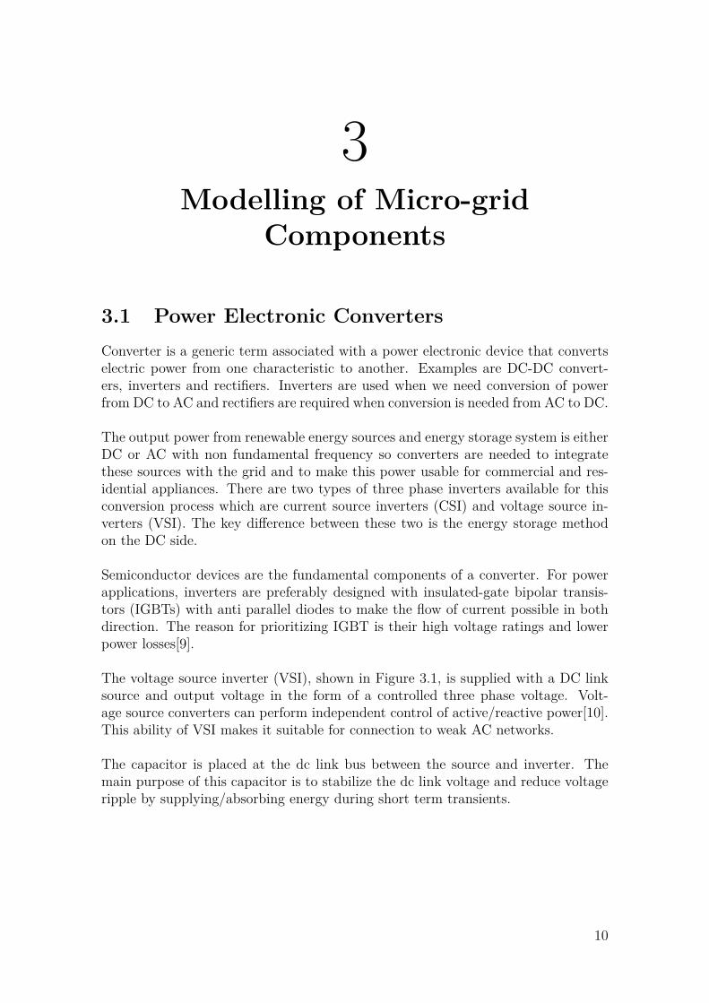
The voltage source inverter (VSI), shown in Figure 3.1, is supplied with a DC linksource and output voltage in the form of a controlled three phase voltage. Volt-age source converters can perform independent control of active/reactive power[10].This ability of VSI makes it suitable for connection to weak AC networks.
The capacitor is placed at the dc link bus between the source and inverter. Themain purpose of this capacitor is to stabilize the dc link voltage and reduce voltageripple by supplying/absorbing energy during short term transients.
10

3. Modelling of Micro-grid Components
Figure 3.1: Voltage Source Inverter
3.2 Inverters’ Modes of OperationInverters used in the microgrids have normally two modes of operation called "GridFollowing Operation" and "Grid Forming Operation". In the grid following mode,the converter regulates the current injected to the grid by controlling its AC terminalvoltage. This is achieved by synchronizing the inverter’s voltage with the voltage ofthe connection point. In this mode the utility grid sets the reference for voltage andfrequency of the system. In the grid forming mode, on the other hand, the invertersets the microgrid voltage and frequency. During grid connected mode the inverteroperates in the grid following mode while in islanded mode the inverters operate inthe grid forming mode[11][12].
3.3 Interfacing Converter TopologiesFor the successful interface of battery energy storage system and renewable energysources with the grid, different interfacing converter topologies are used dependingupon the type of energy source. These typologies are categorized according to thenumber of stages between the power output from the source and grid connectionpoint.
For the energy source with DC power output such as Solar PV and battery we nor-mally use the single stage interfacing converter but for sources such as wind turbinewe need to have multi stage converters for the desired power quality[13].
3.3.1 Single-Stage Converter TopologyThe input voltage at the DC side of the inverter is called DC link voltage. For anytype of VSI topology, this voltage is kept constant by the inverter. As a general rule,the DC link voltage ranges from Vpeak to 1.5 times Vpeak of the output AC voltageof the inverter[14][15].
In single stage topology, DG source is directly connected with the converter andthe output of the converter is connected with the grid. This type of topology is
11

3. Modelling of Micro-grid Components
becoming more prominent in recent years because it has benefits of higher efficiencyand less complexity due to only single stage. Figure 3.2 sketches the single stagetopology.
Figure 3.2: Single Stage DC-AC Interfacing Converter
The major drawback of this topology is the high ripples on the DC side which re-quire large DC link capacitor[16]. Also, this topology requires an overrated inverterand higher dc output voltage from energy sources. In the single stage topology,multilevel inverters have been increasingly used with better DC voltage utilizationand better power quality[17]. For this thesis, single stage inverter is used in orderto reduce the model complexity.
3.3.2 Double-Stage Converter TopologyFor PVs interfacing with the grid, two stage converter topologies are also used wherethe DC voltage is stepped up in the 1st stage using boost converter and then inverterconverts this high DC voltage to the desired AC output voltage. This additionalstage increases the losses and cost of the system. Double stage topology is shown inFigure 3.3.
Figure 3.3: Double Stage DC-DC-AC Interfacing Converter
There are certain conditions where there can be different amount of radiations fordifferent PV arrays due to angle difference between different panels. Due to this
12

3. Modelling of Micro-grid Components
there might be different voltage output from different panels. Double stage topol-ogy facilitates the connection of panels exposed to different solar radiations to acommon DC bus before converting to AC voltage where a common inverter can beused for inversion process.
Another case of the the double stage topology can be in wind turbine where ACpower with non fundamental frequency is converted to DC and then DC is againconverted to AC power with fundamental frequency as shown in Figure 3.4.
Figure 3.4: Double Stage AC-DC-AC Interfacing Converter
3.3.3 Multi-Stage Converter TopologyIn the multistage converter topology, diode rectifier is used in the first stage toconvert the AC output voltage to DC output voltage. Then, DC-DC converter isused to boost the DC output voltage and finally an inverter is used to convert DCvoltage into AC output voltage. This topology has the advantage of high DC voltagerange but it has lower efficiency and high cost compared to two stage topology[18].
Figure 3.5: Multi Stage DC-AC Interfacing Converter
3.4 Solar PV
3.4.1 Solar PV ComponentsA cell is the smallest and basic unit of a solar PV. The output voltage of one singlecell is too low to interconnect it to the grid. Thus, tens of these smaller units areconnected together in series to form a series cell string. A group of these seriesstrings are combined together to form a PV module. Then, these PV modules arefinally connected together in series or and parallel to from a PV array to fulfill thevoltage and current requirements.
13

3. Modelling of Micro-grid Components
All PV modules in an array are assumed identical for the sake of simplicity. Theschematic of solar PV is shown in Figure 3.6. In the figure, a single solar cell, seriescell string, single PV module and finally a PV array are shown, respectively fromleft to right.
Figure 3.6: Solar PV Components
An array is connected to the inverter for converting its DC output power to AC.Normally multiple arrays are connected together in a solar PV plant.
3.4.2 Equivalent Circuit of a Solar CellThe most commonly used equivalent electrical model of a solar PV is shown inFigure 3.7 [19]. It consists of a current source Ig, a parallel diode, a shunt resistanceRsh and a series resistance Rsr.
Figure 3.7: Equivalent Electrical Circuit of a Solar Cell
The value of Rsr affects the output voltage while Rsh affects the output current soideally Rsr is small and Rsh is large. A solar cell is considered as a continuous DC
14

3. Modelling of Micro-grid Components
current source which is dependent on the solar radiations. The amount of currentis directly proportional to the intensity of radiations. The current Ig is given as
Ig = ISCRG
GR
[1 + αT (TC − TCR)] (3.1)
where G is the irradiance value in W/m2 and ISCR is the short circuit current at thereference solar radiation GR and the reference cell temperature TCR. The parameterαT is a constant and is known as the temperature coefficient of the photo current.For silicon solar cell its value is estimated as αT = 0.0017 A/K.
3.4.3 V-I Characteristics of Solar PVThe current and voltage output from a solar PV has an exponential curve whichdepends upon the irradiation. The VI characteristic curve of a solar PV is shownin Figure 3.8
Figure 3.8: VI Characteristic of the Solar PV
The point of the maximum current output corresponds to short circuit current andthe point of the maximum voltage output corresponds to the open circuit voltage.There are different combinations of V and I in the curve for different power outputsbut there is only one point on the whole curve where the power output is maximum.This point corresponding to the maximum value of the power output from solar PVis referred as maximum power point(MPP). The power at the MPP is given by
PMP P = IMP PVMP P (3.2)
3.4.4 Arrangement of ModulesThe output power from the PV array is the function of solar irradiance and temper-ature. The inverter power rating should match the maximum power output fromthe solar PV and its controller should regulate the voltage at the DC link accordingto the desired output power.
Solar PV array has been designed to produce a certain maximum power againststandard irradiance and temperature values. Table 3.1 shows the configuration of
15

3. Modelling of Micro-grid Components
the components in series/parallel to obtain the desired maximum power outputand corresponding voltage, and the power output for this configuration is shown inFigure 3.9.
Table 3.1: PV Parameters for the Modelling
Number of modules connected in series per array 30Number of module strings in parallel per array 60Number of cells connected in series per module 36Number of cell strings in parallel per module 1
With this arrangement shown in Table 3.1, the maximum power output of the solarPV unit is approximately 100 kW and the corresponding voltage value is around 720V . The standard value of irradiance and temperature is 1000 W/m2 and 25 degreeCelsius respectively.
Figure 3.9: Solar output for the configuration in Table 3.1
3.4.5 Power-Voltage Characteristics of Solar PVTo obtain the power-voltage characteristic of the solar PV, simulations are performedaccording to the set up shown in Figure 3.10. In this setup the resistance R1 in seriesis changed and corresponding voltages and power curves are obtained.
Figure 3.10: Setup for plotting the Power-Voltage curves
16

3. Modelling of Micro-grid Components
The test has been performed for different values of irradiance and temperature. Ithas been found that the value of the voltage corresponding to the maximum powerpoint remains almost constant for the different intensity of the solar radiations asshown in Figure 3.11.
Figure 3.11: PV curves at different radiation intensities
3.5 Selection of the BatteryThe battery used in the system is selected as Lithium-Ion battery due to its charac-teristic of high energy density and low maintenance. An equivalent electrical modelof the battery is shown in Figure 3.12.
Figure 3.12: Equivalent Electrical Model of the Battery
The term Rbatt represents the overall internal losses in the battery. Due to the in-ternal losses in the battery, VSOC is kept high e.g 1.05 p.u. so that we can getapproximately 1 p.u at the terminal of the battery. The DC voltage ratings of the
17

3. Modelling of Micro-grid Components
battery is selected as 700 V. During modelling of the battery some assumptions havebeen considered[20].
• Battery Resistance does not change with changing temperature so voltage dropover the entire period is assumed to be constant.
• The internal resistance of the battery is not affected by the amplitude of thecurrent.
• The amplitude of the current does not affect the capacity of the battery.• Self discharge of the battery is not represented.• Charging and discharging cycles have constant value of internal resistance of
the battery.• Battery voltage and battery capacity can not be negative.
The output from the battery is connected to the inverter directly which controls theDC link voltage. The input voltage ratings of the inverter must match the voltageratings of the battery. The equivalent model of the battery is given in Figure 3.12.
3.5.1 Sizing of the BatteryThe capacity of the battery is selected so that during the emergency situation whenthe grid is not connected due to faulty situation and solar PV is not producingenough power, it can supply power to the load. In this thesis, following is the pro-cedure of battery sizing.
• The maximum load has been taken into consideration while calculating thesize of the battery which is approximately 70 kW.
• Back up for 2 hours is selected.• Battery voltage of 700 volts is used to find the Ah rating of the battery.• Battery efficiency of 0.95 is considered.
Assuming all the conditions mentioned above, the Ah rating can be calculated as:
AhRating = Maximum load
Battery voltage∗ Backup hours
Battery efficiency(3.3)
Putting numbers into the equation 3.3
AhRating = 70kW700V ∗ 2h
0.95 = 210Ah (3.4)
3.5.2 Nominal Discharge CurrentThe batteries discharge current is often expressed as the C-rate of the battery [21]."A C-rate is a measure of the rate at which a battery is discharged relative to itsmaximum capacity."
18

3. Modelling of Micro-grid Components
Charging and discharging rates of the the battery depends upon the C rate and itdecides how quickly a battery can discharge its stored energy. A 1C rate means thatdischarge current will discharge the whole battery within one hour. 2C rate meansthat battery will be discharged in half an hour. Similarly, 0.5C rate means that itwill take 2 hours to completely discharge the battery.
Alongwith the ampere-rating of the battery, C-rate is also an important factor ofconsideration while modelling the battery. The C rating has inverse relation withthe battery ampere-hour rating so if we install a high Ampere-hour rating batterywe can significantly decrease the C rate of the battery. In this thesis, the value ofnominal discharge current is selected as 100% which means that battery is following1C rate to supply the power for two hours to the maximum connected load.
19

4Control Techniques in the
Micro-grid
In this chapter, control strategies of the microgrid will be presented. In this thesis,during grid connected mode power will be controlled at the battery converter whileduring isolated mode, the battery converter controls the voltage to maintain thestability of the system. It should be mentioned that, throughout this thesis, thefollowing assumptions are made.
1. Solar PV will generate maximum power during grid connected mode.2. Battery will not charge or discharge during isolated mode so power exchange
from the battery will be zero during isolated mode.3. Solar PV power production is always higher than the connected load.
4.1 Different Reference Frames for VSI ControlThere are three different reference frames which can be described here for the controlof VSI depending upon the application. These reference frames are the so calledabc reference frame, αβ reference frame and dq reference frame. The quantities canbe converted from one reference frame to another reference frame for simplicity andbetter control.
4.1.1 abc Reference FrameIt is also called the natural reference frame. Both linear and non linear controlstrategies can be implemented in this reference frame. Examples of linear controlinclude Proportional Integral (PI) and Proportional Resonant (PR) controllers whilenon linear controllers include hysteresis and deadbeat controllers. The advantage ofthis type of control is that we don’t need to transform the parameters which makesthis type of control less complicated.
4.1.2 Stationary Reference FrameIn this type of control scheme, the three phase electrical quantities are first trans-formed into αβ reference frame, also called Clarke transformation. The result of thistransformation is two-phase AC quantities. PI controller is not feasible to imple-ment in this type of reference frame as PI controller is unable to remove steady state
20

4. Control Techniques in the Micro-grid
errors when controlling sinusoidal quantities. Examples of controllers in this typeof reference frame include proportional resonant (PR) Controller. The principle ofPR controller is that it has a very high gain around the resonance frequency whichhelps in eliminating the steady state error[22].
4.1.3 Synchronous Reference FrameIn this type of control scheme, the three phase electrical quantities are transformedinto synchronous (dq) reference frame which is also called Park transformation. Theadvantage of this transformation is DC quantities which allow the use of integrator.For this thesis work, a synchronous reference frame has been used which allow theuse of integrator to remove steady state errors.
4.2 Current Controller DesignThe most common current controller block diagram for controlling the d and qcurrent individually is shown in Figure 4.1. In this section, each term related tocurrent controller block diagram and its performance will be discussed shortly.
Figure 4.1: Block diagram of a current controller
4.2.1 PI Control LoopThe most commonly controller used in the modern power industry is PI controller[23] as shown in Figure 4.2. The output of the PI controller is the addition of
21

4. Control Techniques in the Micro-grid
proportional and integral term i.e.
CO = CObias +Kce(t) + Kc
τ
∫e(t)dt (4.1)
where
Kc = Controller gainτ = Integral time constante(t) = Error signal at the input of controllerCO = Controller output
The transfer function of the PI controller is given by
H(s) = Kp + Ki
s(4.2)
where Kp and Ki are called the proportional and integral terms respectively.
Figure 4.2: Block Diagram of a PI Controller
4.2.2 Cross Coupling and Feed-forward TermsIn Figure 4.1, it is shown that current cross coupling and feed-forward of the voltageterms are included. The cross coupling term facilitates to remove the impact of acurrent in certain axis (d or q) into another one while using synchronous referenceframes. The feed-forward term removes the impact of variation of the grid voltage.
4.2.3 Phase Locked Loop(PLL)For performing the transformation between different coordinates frames, PhaseLocked Loop(PLL) is used to estimate the the angle of the grid voltage. The PLLblock diagram is shown in Figure 4.3 which is used in this thesis to track the fre-quency of the grid voltage signal when the microgrid is connected with the utilitygrid.
22

4. Control Techniques in the Micro-grid
Figure 4.3: Block Diagram of PLL
For a voltage-oriented coordinate system, the PLL controller tries to force the imag-inary part of the positive-sequence voltage edq to zero. Therefore, the imaginarypart eq normalized to the grid voltage is used as an angle error for the update of thegrid angle and grid frequency[24].
4.3 DC Voltage RegulatorA simple DC voltage regulator is shown in Figure 4.4 which will be implementedto control the DC link voltage in the solar PV controller. In this figure Kpdc andKidc are the proportional and integral controller gains respectively. As solar PV unitis modelled according to its Power-Voltage curve characteristics, the power outputfrom the solar PV will depend upon the DC voltage regulation.
Figure 4.4: Block Diagram of DC Voltage Regulator
4.4 Grid Transition LogicAs described earlier, the microgrid must isolate itself from the utility grid in caseof fault in the utility grid. Two important variables to consider in an AC systemare the voltage and frequency. The frequency and voltage vary abruptly when afault occurs. Thus, in this thesis, isolation and re-connection of the microgrid to theutility grid are decided by the RMS value of the voltage.
A voltage range of ±25% has been selected which gives the lower limit equal to 300V and higher limit equal to 500 V . If the voltage value remains in between the 25%of the base Vrms, the system considers that the microgrid is still connected to theutility grid. If the value goes out of these limits, the isolation signal is activated anda command is sent to open the main breaker. The logic is shown in Figure 4.5.
23

4. Control Techniques in the Micro-grid
Figure 4.5: Transition Logic of Microgrid
The logic blocks are constantly monitoring the real values of the voltage of the maingrid. Once the microgrid is isolated, the SR flip flop latches the signal of breakerfeedback and for the rest of the simulation cycle microgrid remains isolated fromthe utility grid.
4.5 Controller for Solar PVThe objective of the solar PV controller is to obtain the maximum output power fromthe solar PV for a given value of irradiance and temperature in grid connected modeand regulate its power according to the load requirement in isolated mode. Twoseparate control strategies for the solar PV are implemented for the grid connectedand islanded mode and are described next.
4.5.1 Control Strategy in the Grid Connected ModeThe control strategy in the grid connected mode is to produce the maximum powerfrom solar PV unit. This is obtained by regulating the DC link voltage equal toVMP P using a DC voltage regulator as shown in Figure 4.6.
Figure 4.6: Solar PV regulator for grid connected mode
As mentioned in chapter 3, the DC voltage at the maximum power output remainsconstant for different values of solar radiations. For that reason, this value is used
24

4. Control Techniques in the Micro-grid
as a reference to the voltage controller when the microgrid is connected with theutility grid. In this thesis, it is assumed that the power supplied by the solar PVunit is larger than the microgrid load. Thus, the excess of power is supplied to theexternal grid when the microgrid is in grid connected mode.
4.5.2 Control Strategy in the Islanded ModeIn islanded mode, it might be desired to decrease the power generated by the solarPV unit in order to avoid the discharging of the battery. In this thesis, it is desiredthat, in islanded mode, the solar PV power is in balance with the load.
In this case, the signal ∆Udc is added to to the DC voltage regulator shown in Fig-ure 4.7. Through the signal ∆Udc the voltage generated by the converter becomesdifferent from the optimal, thus decreasing the power production from the solar PVunit.
Figure 4.7: Solar PV regulator for islanded mode
The signal ∆Udc comes from secondary (central) controller, which regulates the bat-tery power to zero when there is a transition from grid connected mode to islandedmode. The secondary (central) controller is shown in Figure 4.8.
Figure 4.8: Secondary controller for islanded mode
A shown in Figure 4.8 there is a two state switch for the reference following beforeand after the state of transition. During grid connected mode, the switch is inposition B which in practice means that the controller is deactivated. In the isolatedmode, the switch goes to position A feeding then the battery power Pbatt to the
25
4. Control Techniques in the Micro-grid
controller. Now the regulator acts to bring the battery power to zero when utilitygrid is not connected.
4.6 Battery ControllerFor controlling the battery two different controllers have been implemented depend-ing upon the microgrid operation mode.
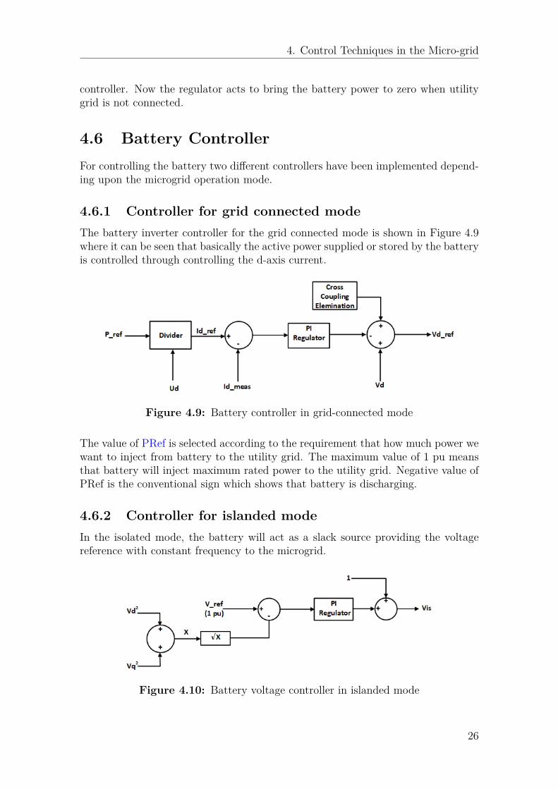
4.6.1 Controller for grid connected modeThe battery inverter controller for the grid connected mode is shown in Figure 4.9where it can be seen that basically the active power supplied or stored by the batteryis controlled through controlling the d-axis current.
Figure 4.9: Battery controller in grid-connected mode
The value of PRef is selected according to the requirement that how much power wewant to inject from battery to the utility grid. The maximum value of 1 pu meansthat battery will inject maximum rated power to the utility grid. Negative value ofPRef is the conventional sign which shows that battery is discharging.
4.6.2 Controller for islanded modeIn the isolated mode, the battery will act as a slack source providing the voltagereference with constant frequency to the microgrid.
Figure 4.10: Battery voltage controller in islanded mode
26

4. Control Techniques in the Micro-grid
In the islanded operation mode, the control strategy has been designed such thatif there is a disturbance in system parameters e.g. load variation or variation inirradiance value the first one to act is battery. Then the solar PV will adjust itspower output such that the power from the battery is zero.
4.6.3 Frequency Control in the Islanded ModeAs we mentioned above, when the microgrid is connected to the utility grid, thePLL is used to calculated the phase angle of the grid voltage and correspondingfrequency of the system. For the islanded mode, the frequency is kept at nominalvalue by giving a fixed value of 50 Hz as shown in Figure 4.11
Figure 4.11: Islanded Mode Frequency Controller
4.7 Utility Grid Power ControllerFor controlling the grid power in grid connected mode, a power controller has beenimplemented as shown in Figure 4.12. The output of this PI controller is the refer-ence for battery regulator which was shown in Figure 4.9.
Figure 4.12: Utility Grid Power Controller
27

5Types of Communication Systems
in the Microgrid
Communication systems are important for the optimal and secure operation of mod-ern microgrid because operations and control system for the renewable dominatedmicrogrid is quite different compared to the existing conventional power systems.Thus, introducing communication systems is unavoidable for the improvement ofthe power system operation[25][26]. In this section, some fundamental technologiesthat are used in today’s microgrid and types of communication architecture will bedescribed. Architecture used for this thesis will also be highlighted.
5.1 Types of Communication in MicrogridDue to the considerable distance between different energy sources, loads and elec-tronic devices in a microgrid, a communication system is necessary for exchangingand sharing information between them. This data can be transmitted by using anyof the following technologies.
• Wired Technology
Wired technology is more reliable in transferring data compared to wire-less technology. It has high data transfer bandwidth and allows point topoint communication between the devices. However, the installation cost ofwired technology is high. The most common examples of wired technologyare Serial Communication RS-232/422/485, Bus technology (e.g. ModBus,ProfiBus,CANBus), Power-line communication (e.g. DLC, PLC, BPLC), andEthernet/Internet of Things (IoT) (e.g. LAN, Optical Fiber Cable).
• Wireless Technology
Wireless technologies have become prominent in recent years for microgrids fordata transmission. They have lower data transmission ratio and are vulnerableto interference and noise but due to the cost effectiveness and easy installationthey are preferred over wired technologies. Keeping in mind future expan-sions of microgrids, wireless technologies are better choice over wired tech-nologies. Examples of wireless technologies include Cellular Technology(e.g.
28

5. Types of Communication Systems in the Microgrid
GSM, CDMA), WiFi, WiMax, ZigBee, ZWave, Bluetooth, Insteon, Radio fre-quency, and Microwave[27].
A comparative analysis of all these wireless technologies has been given in Table 5.1.
Table 5.1: Comparison of various wireless technologies[28],[29]
Characteristic WiFi Bluetooth ZigBee WiMAXCellular(CDMA,GSM)
Range 50 to 100m
10 to 100 m 10 to 100 m Several Km Several Km
OperatingFrequency
2.4 GHz5 GHz 2.4 GHz
868 MHz(Europe)900–928 MHz(North America)2.4 GHz(Worldwide)
2.3, 2.5, and3.5 GHz
9001800 MHz(2G)2.1 GHz (3G)
Data Rate 54 Mbs 24 Mbps 250 Kbps 30–40Mbps
270 Kbps
NetworkTopology
Point toHub
Adhoc, smallnetwork
Ad hoc,peer-to-peeror mesh
Ad hoc,peer-to-peeror mesh
Ad hoc,peer-to-peeror mesh
PowerConsumption High Medium Very low Medium High
5.2 Types of Communication ArchitecturesA microgrid communication architecture can be either one of the following types.
5.2.1 Centralized Control ArchitectureIn a centralized architecture, there is one master control and local controllers for eachsource considered to be slave controllers. The central controller receives informationfrom all slave controllers and then, depending upon the information received fromlocal controllers, the central controller performs the necessary action and sendscontrol signals to local controllers. Figure 5.1 shows the layout of a centralizedcommunication control architecture. One typical example of a centralized structureis Supervisory Control and Data Acquisition (SCADA)[30].
29

5. Types of Communication Systems in the Microgrid
Figure 5.1: Centralized Communication Architecture
The drawback of centralized architecture is if the central controller fails, the wholesystem collapses. Also, size of the controller gets higher and communication networkcomplexity increases in case of a centralized architecture.
5.2.2 Decentralized Control ArchitectureAs we stated in the above paragraph that centralized architecture has a very highreliance on the central controller. Due to this reason, paradigm and trends are shift-ing towards decentralized architectures which is also termed as Multi-agent System(MAS). As expressed in [31], "An agent is an autonomous entity that can perceiveand react to its environment and communicate with others to achieve its local goal."In a decentralized communication architecture, these agents communicate and col-laborate with each other for the stable system operation and hence there is nodependency on the central controller.
When it comes to the benefits of this strategy we can say that in a MAS communica-tion architecture, all the agents within the system have identical characteristics andhence avoid master slave configuration. Another important point is if an entity failsin a decentralized architecture it does not affect the performance of overall system.The communication between agents can either be peer to peer (not involving anyseparate server) or non peer to peer[32]. MAS architecture is shown in Figure 5.2
Figure 5.2: Centralized Communication Architecture
5.3 Communication Protocols in MicrogridFor two or more entities to share information among them, they have to follow acertain set of communication rules under which they can communicate with eachother. This set of rules or systems which enable the entities to exchange data be-tween them is called communication protocol. Today, there are various protocols
30

5. Types of Communication Systems in the Microgrid
available for communication between the devices in a microgrid and selection de-pends upon different factors such as communication type, data traffic, size of systemand available cost etc. Nowadays, IEC 61850 has become as an international com-munication protocol in power industry for communication among electronic devicesin microgrid or substation[33]. This protocol has the following major benefits.
1. Communication bandwidth and speed is much higher compared to other pro-tocols.
2. IEC61850 utilizes Parallel Redundancy Protocol, under which each sourcesends out 2 copies of a frame, through 2 different routes. Hence, if one pathfails, the data will still reach the destination via the alternative route, pre-venting downtime.
3. It allows information exchange and cooperation between Intelligent ElectronicDevices (IEDs) from different manufacturers[34].
In this thesis, a centralized control architecture has been adopted where there is asecondary controller that acts on the battery and a solar PV regulator as a centralcontroller and sends control signals to both local controllers of solar PV and batteryunits. Furthermore, the focus will be on the impact when communication failurebetween the devices occurs.
31
6Simulation and Results
This chapter firstly describes the system under study including solar PV unit, bat-tery unit transformer and loads. Secondly, results of base case simulations will bepresented when the system is operating ideally without any communication delays.Finally, communication delays will be introduced between the controllers communi-cation for the analysis and results will be presented.
6.1 System DescriptionThe schematic of the microgrid used for this thesis is shown in Figure 6.1.
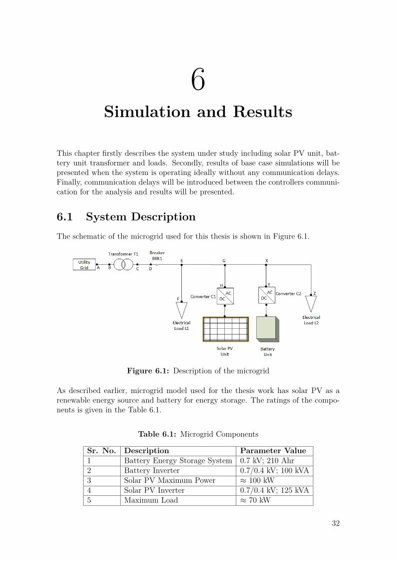
Figure 6.1: Description of the microgrid
As described earlier, microgrid model used for the thesis work has solar PV as arenewable energy source and battery for energy storage. The ratings of the compo-nents is given in the Table 6.1.
Table 6.1: Microgrid Components
Sr. No. Description Parameter Value1 Battery Energy Storage System 0.7 kV; 210 Ahr2 Battery Inverter 0.7/0.4 kV; 100 kVA3 Solar PV Maximum Power ≈ 100 kW4 Solar PV Inverter 0.7/0.4 kV; 125 kVA5 Maximum Load ≈ 70 kW
32

6. Simulation and Results
Three phase ∆Y distribution transformer is connected between the point of PCCand 20 kV transmission line. The specifications of the transformer is given in theTable 6.2
Table 6.2: Transformer Specifications
Sr. No. Parameter Description Parameter Value1 Power rating of the transformer 125 kVA2 Winding connection ∆y3 Positive sequence leakage reactance 4 %4 Primary voltage 20 kV5 Secondary voltage 0.4 kV
In Table 6.3, cables specification are described which have been used in the thesiswork. The values have been taken from[35]. All cables are mentioned according tothe nodes as shown in Figure 6.1.
Table 6.3: Cables Specifications
Sr. No. Node Distance b/wnodes (m) Line Type Rph
(ohm/km)Xph
(ohm/km)1 A-B 10 4x120 mm2Al 0.284 0.0832 C-D 5 4x120mm2Al 0.284 0.0833 E-F 30 4x6 mm2Cu 3.690 0.0944 G-H 30 4x35 mm2Cu 0.574 0.2945 X-Y 30 4x16 mm2Cu 1.380 0.0826 X-Z 30 4x25 mm2Cu 0.871 0.081
The values of the reactor inductance, reactor resistance and DC link capacitor,shown in Figure 6.2, for battery inverter and solar PV inverter are given in theTable 6.4.
Figure 6.2: Converter schematic with electrical components
Table 6.4: L,R and C Values
Sr. No. Element Battery Inverter Solar PV Inverter1 DC link capacitor 5102.04 µF 4897.959 µF2 AC reactor inductance 0.407437 mH 0.424413 mH3 AC reactor resistance 1.28 mΩ 1.33 mΩ
33

6. Simulation and Results
6.2 Base Case SimulationsThis section describes the base case simulation i.e. without any kind of communi-cation delays during the transition and for both solar and battery controller.
6.3 Battery power regulation with excess powerfrom Solar PV
In this section, the simulation results are obtained when the microgrid is operatingin islanded mode. Also, as mentioned previously, in this thesis the maximumpower of the solar PV is always assumed to be greater than the load. The controlstrategies for the islanded mode have been described in Chapter 4.
6.3.1 Constant load with variation in solar radiation andpower production
The system is operating in islanded mode in steady state. There is no variation inthe load but irradiance value is varying momentarily because of cloud effects, forexample. The simulation sequence is as follows
@t=0 s: Simulation starts with irradiance = 1000 W/m2 and Load = 68 kW@t=1.5 s: Irradiance value goes down to 750 W/m2
@t=3 s: Irradiance value increases upto 900 W/m2
@t=4 s: Irradiance value goes down again to 800 W/m2
Figure 6.3: Battery controller in grid-connected mode
34

6. Simulation and Results
Figure 6.4: Battery Inverter Power Output
Figure 6.5: Solar PV Output
Figure 6.3 shows the variation in irradiance value while Figure 6.4 and Figure 6.5show the results of power output from battery and solar PV inverters respectively.From the figures it can be seen that the final battery power exchange is zero ac-cording to our control strategy in islanded mode. Solar PV unit adjusts its out putpower according to the load requirement as per its control strategy in islanded mode.
6.3.2 Constant irradiance with variation in loadThe microgrid is again operating in islanded mode.This case investigates the systemperformance when there is variation in the connected load but the irradiance valueon the solar PV unit is maintained constant to a value of 800 W/m2. The simulationsequence for this case is as follows:
@ t=0 s: Simulation starts with Irradiance = 800 W/m2 and load = 55.5 kW@ t=2 s: Load of 42.75 kW is disconnected and the maximum connected load is12.75 kW@ t=3 s: Load increases and total connected load is 25.35 kW
35

6. Simulation and Results
@ t=4 s: Load of 12.75 kW is disconnected and total connected load is 12.6 kW
As per the control strategy of the solar PV , the controller immediately respondsto keep the power flow in balance while there is variation in load. The voltage onthe DC link of the PV unit is regulated and brings the solar power to match theload according to the Power-Voltage curve of the solar PV. Figure 6.6 and Figure6.7 show power output from battery and solar PV respectively.
Figure 6.6: Battery Inverter Power Output
Figure 6.7: Solar PV Output
Battery power in this case remains at zero value because the solar PV is able tomeet the load.
It can be noted that compared to the previous case, more oscillations are observedin this case. This might be because we face large difference between the load andgeneration and the controller needs to respond more aggressively to have balancebetween them in case of variations compared to the previous case.
36

6. Simulation and Results
6.4 Transition from Grid-connected to IslandedMode
6.4.1 Large Generation of Solar with Constant LoadIn this case, the load is kept constant and the solar PV unit produces more powerthan the load. The battery unit is also capable of providing power as it is charged.The remaining extra power from solar PV along with the battery power will flow tothe utility grid as long as microgrid is connected with the utility grid.
A three phase fault occurs at t=2 s thus the RMS voltage decreases below the mini-mum limit, the main breaker opens and the microgrid isolates itself from the utilitygrid. The breaker opening event is communicated to the battery unit controller,which makes it to switch from the grid connected mode to isolated mode immedi-ately, assuming that there is no delays in the communication channel.
In isolated mode, the battery unit controller regulates its power to zero value asthere is excess power from solar PV. The voltage value on the DC link of the PVinverter is adjusted such that the power production from solar PV is reduced aftertransition according to the load requirement. The PV power generation is balancedwith the connected load after the controllers act and system reaches new steadystate values.
Table 6.5: Steady-state power values before and after the transition
G(W/m2)
PL
(kW)
PV Power(kW)
Battery Power(kW)
Power togrid (kW)
Beforefault
Afterfault
Beforefault
Afterfault
Beforefault
Afterfault
1000 68 103.1 69.4 124.9 0 152.53 0800 68 82.58 69.4 125 0 133.79 0
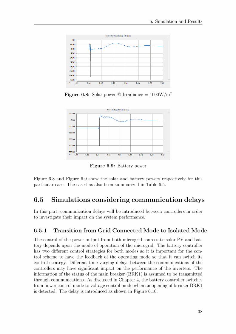
Two different radiation values have been selected for the case analysis as shown inTable 6.5 and the battery produces 125 kW . The excess amount of power fromsolar PV and the power from battery flows towards the utility grid before the fault,but, after the fault, the battery power is regulated to zero and solar PV adjusts itspower according to the load requirement. After transition, no power flows towardsthe utility grid as the microgrid is disconnected from the utility grid.
37
6. Simulation and Results
Figure 6.8: Solar power @ Irradiance = 1000W/m2
Figure 6.9: Battery power
Figure 6.8 and Figure 6.9 show the solar and battery powers respectively for thisparticular case. The case has also been summarized in Table 6.5.
6.5 Simulations considering communication delaysIn this part, communication delays will be introduced between controllers in orderto investigate their impact on the system performance.
6.5.1 Transition from Grid Connected Mode to Isolated ModeThe control of the power output from both microgrid sources i.e solar PV and bat-tery depends upon the mode of operation of the microgrid. The battery controllerhas two different control strategies for both modes so it is important for the con-trol scheme to have the feedback of the operating mode so that it can switch itscontrol strategy. Different time varying delays between the communications of thecontrollers may have significant impact on the performance of the inverters. Theinformation of the status of the main breaker (BRK1) is assumed to be transmittedthrough communications. As discussed in Chapter 4, the battery controller switchesfrom power control mode to voltage control mode when an opening of breaker BRK1is detected. The delay is introduced as shown in Figure 6.10.
38

6. Simulation and Results
Figure 6.10: Delays in the transfer of voltage references
The controller follows the reference according to the grid connected mode as there isdelay in the feedback of breaker which disturbs the voltage and power values duringthe delayed time. Although delay is introduced only in the controller of battery,it also effects the output power of solar PV unit due to the fact that the signal ofbattery power regulator output i.e. ∆Udc is also an input to solar PV controller toadjust the solar PV inverter’s output power during the isolated mode. In Figure 6.11and Figure 6.12, a comparative analysis of the active power from battery and solarPV is shown for different time delays which occur in the feedback of transition. Thecurves in the following figures show a comparison when system returns to a steadystate after some transients.
Figure 6.11: Battery power comparison with different time delays
39
6. Simulation and Results
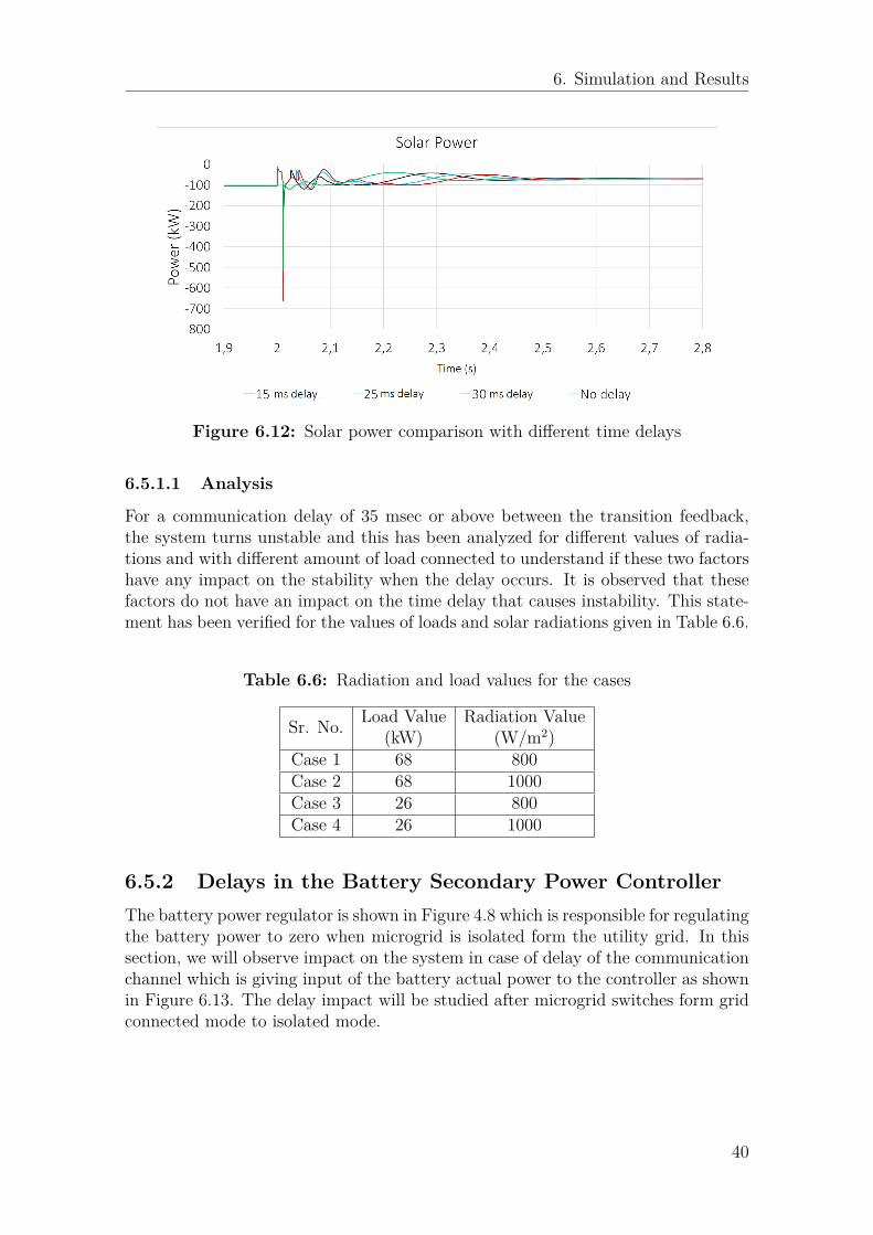
Figure 6.12: Solar power comparison with different time delays
6.5.1.1 Analysis
For a communication delay of 35 msec or above between the transition feedback,the system turns unstable and this has been analyzed for different values of radia-tions and with different amount of load connected to understand if these two factorshave any impact on the stability when the delay occurs. It is observed that thesefactors do not have an impact on the time delay that causes instability. This state-ment has been verified for the values of loads and solar radiations given in Table 6.6.
Table 6.6: Radiation and load values for the cases
Sr. No. Load Value(kW)
Radiation Value(W/m2)
Case 1 68 800Case 2 68 1000Case 3 26 800Case 4 26 1000
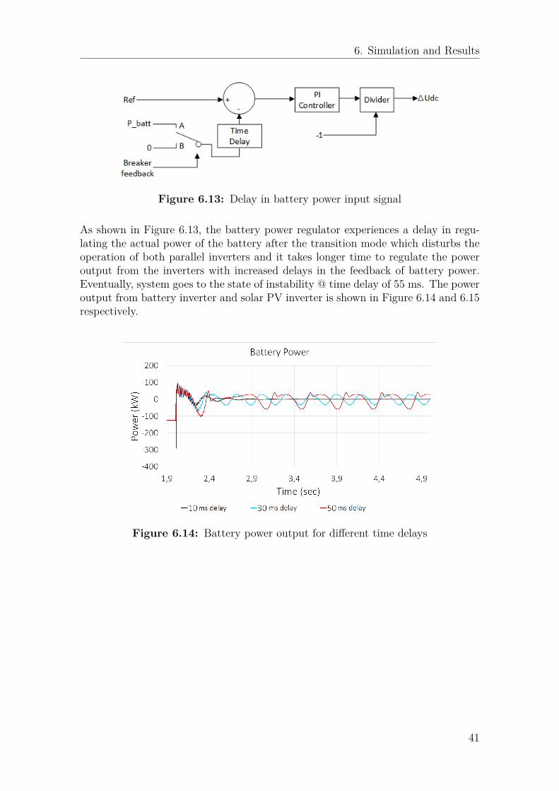
6.5.2 Delays in the Battery Secondary Power ControllerThe battery power regulator is shown in Figure 4.8 which is responsible for regulatingthe battery power to zero when microgrid is isolated form the utility grid. In thissection, we will observe impact on the system in case of delay of the communicationchannel which is giving input of the battery actual power to the controller as shownin Figure 6.13. The delay impact will be studied after microgrid switches form gridconnected mode to isolated mode.
40
6. Simulation and Results
Figure 6.13: Delay in battery power input signal
As shown in Figure 6.13, the battery power regulator experiences a delay in regu-lating the actual power of the battery after the transition mode which disturbs theoperation of both parallel inverters and it takes longer time to regulate the poweroutput from the inverters with increased delays in the feedback of battery power.Eventually, system goes to the state of instability @ time delay of 55 ms. The poweroutput from battery inverter and solar PV inverter is shown in Figure 6.14 and 6.15respectively.
Figure 6.14: Battery power output for different time delays
41

6. Simulation and Results
Figure 6.15: Solar power output for different time delays
This case has also been studied for different combination of parameters i.e. loadand irradiance. After analyzing different combinations, it has been found that irre-spective of the load or irradiance values when solar PV is generating power closerto the connected load, the system remains stable even at the longer time delaysthan 55 ms. One reason for this can be that secondary controller does not have tocompensate for a larger difference after the fault occurs since the battery controlleracts immediately so it is easier to remove smaller difference in shorter time which ishelpful in keeping system alive. The case investigated for different loads and solarirradiance values is shown in Table 6.7.
Table 6.7: Analysis of the case under different conditions
Sr.No. Irradiance Value(W/m2)
PL
(kW)Time Delay(55 ms) System Status
1 1000 68 55 Unstable2 800 68 55 Stable3 1000 90 55 Stable4 1200 90 55 Unstable5 300 26 55 Stable
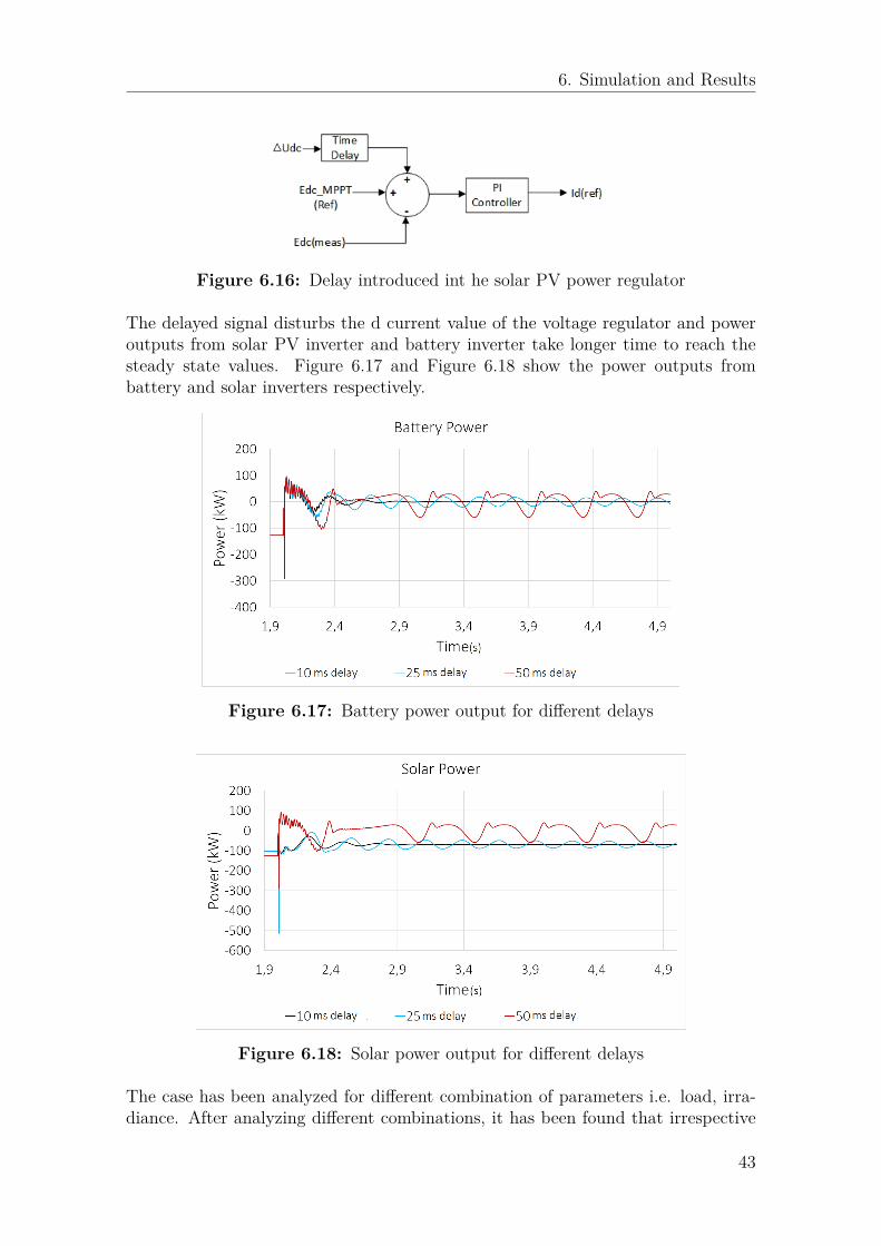
6.5.3 Delays in the Solar PV RegulationAs shown in the controller of solar PV i.e. Figure 4.6 , it produces maximum powerin case of grid connected mode and adjusts its power according to the load connectedin the isolated mode. For adjusting its power to match the value of the connectedload the output signal of the battery power regulator comes to the solar PV voltagecontroller so that it can reduce its power accordingly in islanded mode. In this case,the delay is introduced in receiving this signal in the islanded mode as shown inFigure 6.16.
42
6. Simulation and Results
Figure 6.16: Delay introduced int he solar PV power regulator
The delayed signal disturbs the d current value of the voltage regulator and poweroutputs from solar PV inverter and battery inverter take longer time to reach thesteady state values. Figure 6.17 and Figure 6.18 show the power outputs frombattery and solar inverters respectively.
Figure 6.17: Battery power output for different delays
Figure 6.18: Solar power output for different delays
The case has been analyzed for different combination of parameters i.e. load, irra-diance. After analyzing different combinations, it has been found that irrespective
43

6. Simulation and Results
of the amount of load or irradiance when solar PV is generating power closer to theconnected load the system avoids instability even after 50 ms. One reason for thiscan be that controller does not have to compensate for a larger difference after faultoccurs so it is easier to remove smaller difference in shorter time which is helpful inkeeping system alive. The studied cases are summarized in Table 6.8
Table 6.8: Analysis of the case under different conditions
Sr. No. Irradiance Value(W/m2)
PL
(kW)Time Delay(55 ms) System Status
1 1000 68 55 Unstable2 800 68 55 Stable3 1000 90 55 Stable4 1200 90 55 Unstable5 300 26 55 Stable
6.6 Delays in communication in islanded modeIn this section, base case simulation results will be analyzed when there is delayin coordination between the converters’ controllers while microgrid is operating inislanded mode.
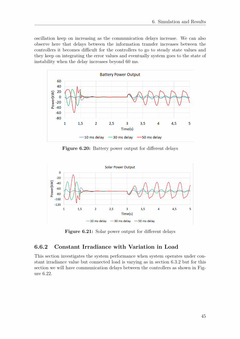
6.6.1 Constant Load with Variation in IrradianceThis section describes the system behaviour when system is operating under constantload but irradiance value is varying as in section 6.3.1 but for this section we willhave communication delays between the controllers which is shown in Figure 6.19.
Figure 6.19: Battery power output for different delays
The simulation sequence is as follows
@t=0 s: Simulation starts with irradiance = 1000 W/m2 and Load = 68 kW@t=1.5 s: Irradiance value goes down to 750 W/m2
@t=3 s: Irradiance value increases upto 900 W/m2
The power output from the battery unit inverters solar PV inverter is shown inFigure 6.20 and Figure 6.21 respectively. As we can see here, compared to Section6.3.1, there are more variations in the power output from the inverters and the
44
6. Simulation and Results
oscillation keep on increasing as the communication delays increase. We can alsoobserve here that delays between the information transfer increases between thecontrollers it becomes difficult for the controllers to go to steady state values andthey keep on integrating the error values and eventually system goes to the state ofinstability when the delay increases beyond 60 ms.
Figure 6.20: Battery power output for different delays
Figure 6.21: Solar power output for different delays
6.6.2 Constant Irradiance with Variation in LoadThis section investigates the system performance when system operates under con-stant irradiance value but connected load is varying as in section 6.3.2 but for thissection we will have communication delays between the controllers as shown in Fig-ure 6.22.
45

6. Simulation and Results
Figure 6.22: Delay introduced int he solar PV power regulator
The simulation sequence is as follows@ t=0 s: Simulation starts with Irradiance = 800 W/m2 and load = 55.5 kW@ t=2 s: Load of 42.75 kW is disconnected and the maximum connected load is12.75 kW@ t=3 s: Load increases and total connected load is 25.35 kW@ t=4 s: Load of 12.75 kW is disconnected and total connected load is 12.6 kW
The power output from the battery unit inverters solar PV inverter is shown inFigure 6.23 and Figure 6.24 respectively. As we can see from the figures, thatoscillation are very much prominent in this section compared to section 6.3.2 andalso compared to section 6.6.2. the controllers are unable to regulate their power asper ideal situation because of the system transients.
Figure 6.23: Battery power output for different delays
46
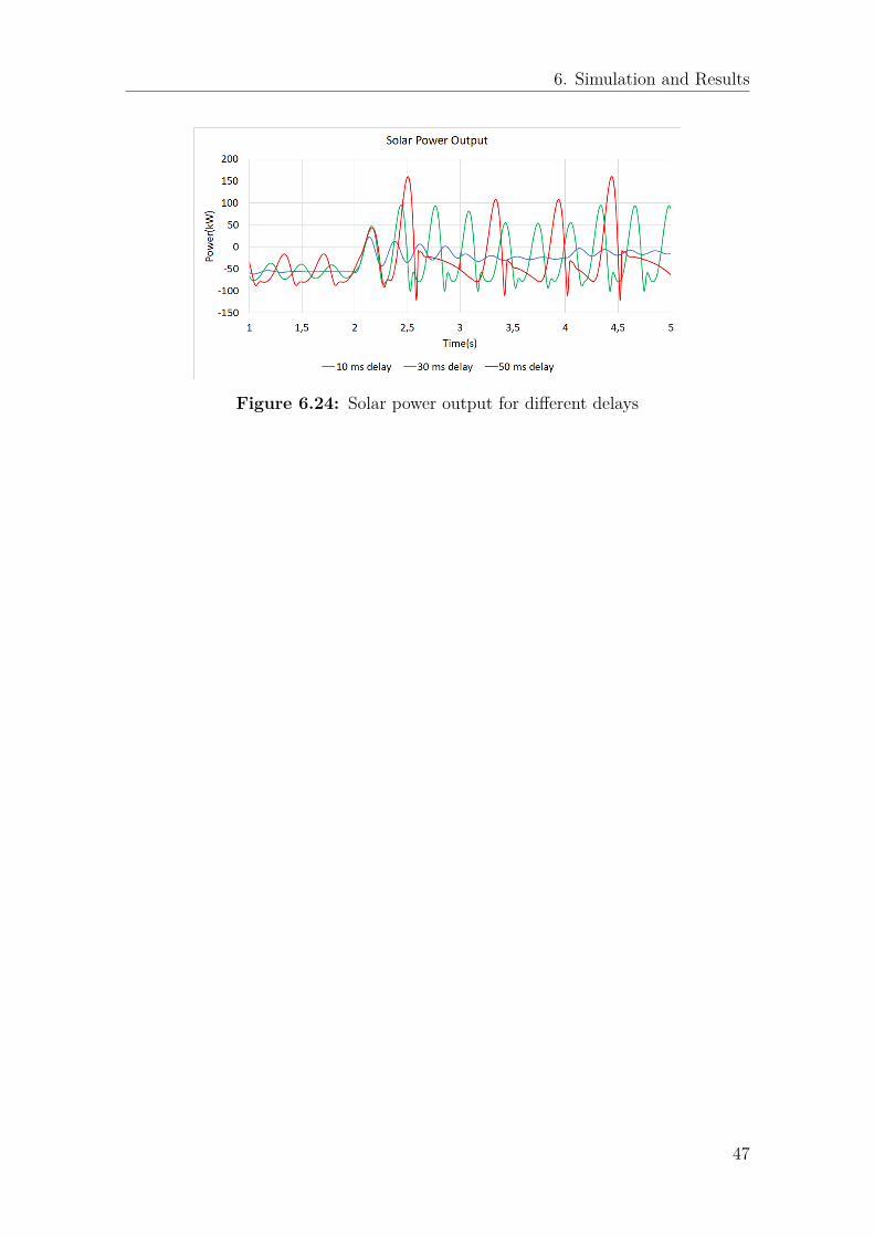
6. Simulation and Results
Figure 6.24: Solar power output for different delays
47
7Conclusion and Future Work
7.1 ConclusionThe impact of different communication delays in a microgrid system composed ofsolar PV and battery units as its own energy sources has been studied in this thesis.The microgrid is connected with utility grid trough a transformer and breaker butalso capable of disconnected form it. Thus, the system under study is implementedwith two different control strategies for grid connected and islanded mode. For suchoperation modes, controllers have been implemented accordingly.
In grid connected mode, a power controller has been implemented such that thepower exchange between the microgrid and the utility grid remains constant. Inthis case, the battery output power is regulated to obtain the desired power ex-change. In islanded mode, a secondary controller has been implemented such thatthe power from the battery unit is zero. This is achieved by regulating the poweroutput from the solar PV unit to match the load consumption.
The system performance has been studied considering the following different cases.1. Transition from grid connected mode to islanded mode.2. Microgrid operating in islanded mode.
It has been found that the system is proner to instability when there is delay in in-formation exchange during transition from the grid connected mode to the islandedmode. Delays in the signal that indicates the status of the breaker that connectsthe microgrid with the utility are the most adverse ones compared to the delays inother parts of the system, such as the battery controller or the solar PV controller.This might lead to the complete collapse if delays exceed a certain time, which, inthe particular system studied in this thesis is around 35 ms.
In islanded mode, the solar PV controller is tested by varying the solar irradianceand load. It is found that, in the case of solar irradiance variation, the system canturn unstable for communication delays greater than 60 ms. On the other hand, inthe case of load variations, it is observed that the transients are more severe com-pared to the previous case.
It should be mentioned that the time delays can go greater if the amount of powerinjection capability by the solar PV is very close to the load demand. This is due
48

7. Conclusion and Future Work
to the fact that, in these cases, the controllers have to compensate for a smallermismatch compared to when the differences are significant.
7.2 Future WorkThere are some important points which can be studied for future work.
1. For this thesis work, single stage topology of the converters is used by hav-ing an assumption that all solar PV arrays are alike and generating the sameamount of output voltage. For future work, one can look into more practicalcase when voltages of the solar PV arrays vary and double stage topology isneeded for having same amount of voltage at the input of inverter before in-version.
2. This thesis work included only solar PV unit and battery energy storage sys-tem. For future work, wind turbine can be integrated into this model if expan-sion of the system is needed in the future. This will follow the same procedurei.e modelling of the wind turbine and then implement some control strategiesto control the output power from wind.
3. In some literature, it is said for a good performance of the DC voltage controlanother type of controller called Fuzzy Controller can be used which has twoinputs. One input is the error between reference and actual signal and thesecond input is the representation of the variation of this error[36]. So I wouldsuggest to use Fuzzy Controller in case where irradiance value is changing fre-quently.
49

Bibliography
[1] Suleiman M. Sharkh, Mohammad A. Abu-Sara, Georgios I. Orfanoudakis,Babar Hussain, "Power Electronic Converters for Microgrids; First Edition",Wiley-IEEE Press, June 2014.
[2] Zhiling, Q. and Guozhu, "Study and design of grid connected inverter for 2MW wind turbine", in IEEE Industry Applications Annual Meeting, NewOrleans, USA, September 23-27, 2007.
[3] International Energy Agency, "Renewables 2017-Analysis and Forecasts to2022", October,2017.
[4] Qu Tianyi, "The Economy and Environmental Benefit of the Microgrid" inTrans Tech Publications, Switzerland, 2013.
[5] Victor Mouton, "The Impact of Microgrids on the Energy Sector" Master’sDissertation, Ghent University, Ghent, Belgium, 2017.
[6] National Electrical Manufacturers Association (NEMA), "Microgrids, MacroBenefits: How to talk to decision makers about building your own electricalpower system", USA, 2014.
[7] Oleksandr Starynets, "Communication in microgrids and virtual power plants"Master thesis in Electrical Engineering, Department of Electrical Engineering,The Arctic University of Norway, Norway, June 2016.
[8] A. A. Salam, A. Mohamed and M. A. Hannan, "Effects of the SyntheticInertia from Wind Power on the Total System Inertia: Simulation Study"in 2nd International Symposium On Environment Friendly Energies AndApplications, Newcastle upon Tyne, UK, June 25-27, 2012.
[9] Carl Blake and Chris Bull, "IGBT or MOSFET: Choose Wisely", InternationalRectifier, USA.
[10] Michael P. Bahrman, Jan G. Johansson and Bo A. Nilsson "Voltage SourceConverter Transmission Technologies - The Right Fit for the Application" inIEEE Power Engineering Society General Meeting, Toronto, Canada, July
50
Bibliography
13-17, 2003.
[11] Woo-Kyu Chae, Jong-Nam Won, Hak-Ju Lee, Jae-Eon Kim and Jaehong Kim"Comparative Analysis of Voltage Control in Battery Power Converters forInverter-Based AC Microgrids", energies, MDPI, July 28, 2016.
[12] Mohsen Nemati, Stefan Tenbohlen, Muhammad Imran, Holger Mueller andMartin Braun "Frequency and Voltage Control in Microgrids: Modelingand Simulations in Islanded Mode", in IEEE PES Innovative Smart GridTechnologies, Istanbul, Turkey, October 12-15, 2014.
[13] Xiongfei Wang, Josep M. Guerrero, Zhe Chen and Frede Blaabjerg " Dis-tributed Energy Resources in Grid Interactive AC Microgrids", in The 2ndInternational Symposium on Power Electronics for Distributed GenerationSystems, Hefei, China, June 16-18, 2010.
[14] Malte Mohr and Friedrich W. Fuchs, "Comparison of Three Phase CurrentSource Inverters and Voltage Source Inverters Linked with DC to DC BoostConverters for Fuel Cell Generation Systems", in European Conference onPower Electronics and Applications, Dresden, Germany, August 07, 2006.
[15] N.E. Zakzouk, A.K. Abdelsalam, A.A. Helal and B.W. Williams "PV SinglePhase Grid Connected Converter: DC-link Voltage Sensorless Prospective", inIEEE Journal of Emerging and Selected Topics in Power Electronics, Volume5, page 526-546, December 08, 2016.
[16] Yaosuo Xue, Liuchen Chang, Sren Baekhj Kjaer, J. Bordonau and T. Shimizu,"Topologies of Single-Phase Inverters for Small Distributed Power Generators:An Overview", in IEEE Transactions on Power Electronics Volume:19, Issue:5,pages 1305 - 1314, September 2004.
[17] Yunwei LI and Farzam Nejabatkhah, "Overview of Control, Integration andEnergy Management of Microgrids", Journal of Modern Power Systems andClean Energy, Volume:2, Issue:3, pp 212–222, September 2014.
[18] Kyle Clark, "Power Conversion System Architectures for Grid Tied EnergyStorage; Workshop on High Megawatt Electronics: Technology RoadmapWorkshop for Increased Power Electronic Grid Applications and Devices",National Institute of Standards and Technology, Technology Administration,U.S. Department of Commerce, May 24, 2012.
[19] Miguel Pareja Aparicio, José Pelegrí-Sebastiá, Tomas Sogorb and VicenteLlario, "Modeling of photovoltaic cell using free software application for train-ing and design circuit in Photovoltaic Solar Energy" Chapter 6, March 13, 2013.
51
Bibliography
[20] PSCAD Manual
[21] MIT electric vehicle team, "A guide to understanding battery specifications",December 2008.
[22] Frede Blaabjerg, Remus Teodorescu, Marco Liserre and Adrian V. Timbus,"Overview of Control and Grid Synchronization for Distributed Power Gener-ation Systems" in IEEE Transactions on Industrial Electronics, Volume:53 ,Issue:5 , October 2006.
[23] K. Smriti Rao and Ravi Mishra, "Comparative Study of P, PI and PIDController for Speed Control of VSI-fed Induction Motor", InternationalJournal of Engineering Development and Research (IJEDR), ISSN:2321-9939,Vol.2, Issue 2, pp.2740-2744, June 2014.
[24] MEBTU BEZA, "Power System Stability Enhancement Using Shunt-connectedPower Electronic Devices with Active Power Injection Capability", Ph.D. dis-sertation, Chalmers University of Technology, Gothenburg, Sweden, January,2015.
[25] Srivats Shukla, Yi Deng, Sandeep Shukla and Lamine Mili, "Constructionof a Microgrid Communication Network", in IEEE Innovative Smart GridTechnologies conference, Washington, DC, USA, February 19-22, 2014.
[26] Cunxu Wang, Xingfeng Xiao, Aijun Zhang and Xiaoyu Sun "Research onOperation and Control of Micro-Grid System", July, 2016.
[27] Habib ELKHORCHANI, Khaled GRAYAA; Smart Micro Grid Power WithWireless Communication Architecture, Case of a hybrid power systemPV/Wind/ Battery in International Conference on Electrical Sciences andTechnologies in Maghreb (CISTEM),Tunis, Tunisia, November 3-6, 2014.
[28] Made A. Setiawan, Farhad Shahnia, Sumedha Rajakaruna and ArindamGhosh "ZigBee-Based Communication System for Data Transfer WithinFuture Microgrids" in IEEE Transactions on Smart Grid, Volume: 6 , Issue: 5, September 2015.
[29] Trong Nghia Le, Wen-Long Chin and Hsiao-Hwa Chen, “Standardizationand Security for Smart Grid Communications Based on Cognitive RadioTechnologies - A Comprehensive Survey", in IEEE Communications SurveysTutorials, Volume:19, Issue:1, Pages: 423-445, September 27, 2016.
[30] Kate Monteiro, Michel Marot and Hatem Ibn-khedher, "Review on MicrogridCommunications Solutions: A Named Data Networking-Fog Approach" inIEEE 16th Annual Mediterranean Ad Hoc Networking Workshop, Budva,
52

Bibliography
Montenegro, June 28-30, 2017.
[31] Niannian Cai and Joydeep Mitra, "A Decentralized Control Architecturefor a Microgrid with Power Electronic Interfaces" in North American PowerSymposium, Arlington, TX, USA, September 26-28, 2010.
[32] V. Lakshminarayanan, V. Chandra Sekar, and K. Rajashekara, "Novel Com-munication Architecture for Multi-Agent Systems in Autonomous Microgrid"in IEEE Power and Energy Society General Meeting, Boston, USA, July 17-21,2016.
[33] ABB, "IEC 61850 Communication Protocol Manual", April, 2011.
[34] Jasonsoh, "What is IEC 61850 and Why is it Necessary?" Phoenix Contact,March 30, 2016.
[35] Stavros Papathanassiou, Nikos Hatziargyriou and Kai Strunz, "A BenchmarkLow Voltage Microgrid Network" in CIGRE symposium, "Power systems withdispersed generation: technologies, impacts on development, operation andperformances", Athens, Greece, April, 2005.
[36] Arezki Fekik, H. Denoun, N. Benamrouche, Nabil Benyahia; Comparative studyof PI and FUZZY DC-voltage control for Voltage Oriented Control-PWM rec-tifier
53