Mueller polarimetry as a tool for detecting asymmetry in...
6
Mueller polarimetry as a tool for detecting asymmetry in diffraction grating profiles Tatiana Novikova a) and Pavel Bulkin LPICM, CNRS, Ecole Polytechnique, Palaiseau 91128, France Vladimir Popov b) Skobeltsyn Institute of Nuclear Physics, Moscow State University, Russia Bicher Haj Ibrahim and Antonello De Martino LPICM, CNRS, Ecole Polytechnique, Palaiseau 91128, France (Received 19 March 2011; accepted 19 July 2011; published 9 September 2011) Reflected Mueller matrix spectra were measured and simulated for asymmetrical photoresist master diffraction gratings in conical mounting (i.e., the direction of grating grooves was not perpendicular to the plane of light incidence). From the electromagnetic reciprocity theorem, Mueller matrix of symmetric grating (composed of only reciprocal materials, and operating in zeroth-order diffraction) is invariant under transposition (M ¼ M t ). For zeroth-order diffraction of asymmetric gratings, the lack of profile rotational symmetry violates this reciprocity and, conse- quently, breaks the symmetry of the above-mentioned matrix. This property of the Mueller matrix of asymmetric gratings was experimentally observed and numerically modeled at all experimental illumination conditions with the exception of planar mounting (the direction of grating grooves was perpendicular to the plane of light incidence), where there is no cross-polarization effect for the gratings composed of isotropic materials. It was demonstrated that optical nonreciprocity of diffraction gratings can be used for unambiguous detection of grating profile asymmetry. In addition, choosing optimal measurement configuration (i.e., azimuthal angles) considerably increases the sensitivity of the detection technique. V C 2011 American Vacuum Society. [DOI: 10.1116/1.3633693] I. INTRODUCTION The metrology of nanogratings is of great importance for many industrial applications. With ever-shrinking chip criti- cal dimensions (CDs) it has become one of the leading fac- tors defining process performance in microelectronics. 1 Nanogratings applications such as laser pulse compression in chirped pulse amplification systems, antireflection structures, and counterfeit protection labels require consistent fabrica- tion of a specified grating design. The nanoimprint grating replication process is widely used for the production of secu- rity holograms. These holograms represent the diffractive structures, composed mainly of diffraction gratings of varied pitches, critical dimensions, and orientations with respect to each other. These structures possess unique diffractive optical properties which are difficult to imitate and, consequently, have high fidelity against counterfeiting. The fabrication process typically consists of two steps: (1) the designed structure is translated into a resist layer (spin- coated over a substrate) by optical or electron-beam lithogra- phy and subsequent etching (the resulting structure is called a master grating); (2) nickel electroplating and mechanical separation of the metal layer deposited on top of the master grating yield a Ni shim. Afterward, the shim is used for the replication of the original structure in a soft plastic layer by either stamping or by the roll-to-roll process. The metrology of Step 1 is of crucial importance to the process, as this step is the most expensive and time consuming part of the repli- cative nanoimprint grating fabrication. Atomic force micros- copy (AFM) and scanning electron microscopy (SEM) characterization techniques, widely used now for metrologi- cal applications, 2–5 can provide images of either the sample surface or the cleaved sample. Although accepted as “golden standards” for grating metrology, these techniques have some drawbacks. They are relatively slow, sometimes sample-destructive, and deliver only local information about samples. During the last few years, there has been growing interest in optical techniques (e.g., reflectometry, ellipsome- try, scatterometry, polarimetry) that provide quality control of such structures. 6–8 The interaction of polarized light with a sample changes the polarimetric properties of the reflected (transmitted) beam, depending on the light wavelength, con- figuration of the measurement (polar and azimuthal angles), and properties of the sample (e.g., refractive indices of sam- ple materials and geometry of the grating). Unlike AFM and SEM, optical measurement techniques are fast and nondes- tructive, and spatial information is averaged over the spot of the probing beam (typically the diameter of the spot is a few tens of microns). In terms of Stokes formalism, any sample, even a depola- rizing one, can be described by its real 4 4 Mueller matrix. 9 The measurements of the Mueller matrix at an arbitrary orien- tation of the plane of light incidence with respect to the direc- tion of the grooves of one-dimensional (1D) grating (so called conical mounting) have proved to be a powerful optical a) Electronic mail: [email protected] b) Present address: General Physics Department, Moscow State University, Russia. 051804-1 J. Vac. Sci. Technol. B 29(5), Sep/Oct 2011 1071-1023/2011/29(5)/051804/6/$30.00 V C 2011 American Vacuum Society 051804-1 Author complimentary copy. Redistribution subject to AIP license or copyright, see http://jvb.aip.org/jvb/copyright.jsp
Transcript of Mueller polarimetry as a tool for detecting asymmetry in...
Mueller polarimetry as a tool for detecting asymmetry in diffractiongrating profiles
Tatiana Novikovaa) and Pavel BulkinLPICM, CNRS, Ecole Polytechnique, Palaiseau 91128, France
Vladimir Popovb)
Skobeltsyn Institute of Nuclear Physics, Moscow State University, Russia
Bicher Haj Ibrahim and Antonello De MartinoLPICM, CNRS, Ecole Polytechnique, Palaiseau 91128, France
(Received 19 March 2011; accepted 19 July 2011; published 9 September 2011)
Reflected Mueller matrix spectra were measured and simulated for asymmetrical photoresist
master diffraction gratings in conical mounting (i.e., the direction of grating grooves was not
perpendicular to the plane of light incidence). From the electromagnetic reciprocity theorem,
Mueller matrix of symmetric grating (composed of only reciprocal materials, and operating in
zeroth-order diffraction) is invariant under transposition (M ¼ Mt). For zeroth-order diffraction of
asymmetric gratings, the lack of profile rotational symmetry violates this reciprocity and, conse-
quently, breaks the symmetry of the above-mentioned matrix. This property of the Mueller matrix
of asymmetric gratings was experimentally observed and numerically modeled at all experimental
illumination conditions with the exception of planar mounting (the direction of grating grooves
was perpendicular to the plane of light incidence), where there is no cross-polarization effect
for the gratings composed of isotropic materials. It was demonstrated that optical nonreciprocity
of diffraction gratings can be used for unambiguous detection of grating profile asymmetry.
In addition, choosing optimal measurement configuration (i.e., azimuthal angles) considerably
increases the sensitivity of the detection technique. VC 2011 American Vacuum Society.
[DOI: 10.1116/1.3633693]
I. INTRODUCTION
The metrology of nanogratings is of great importance for
many industrial applications. With ever-shrinking chip criti-
cal dimensions (CDs) it has become one of the leading fac-
tors defining process performance in microelectronics.1
Nanogratings applications such as laser pulse compression in
chirped pulse amplification systems, antireflection structures,
and counterfeit protection labels require consistent fabrica-
tion of a specified grating design. The nanoimprint grating
replication process is widely used for the production of secu-
rity holograms. These holograms represent the diffractive
structures, composed mainly of diffraction gratings of varied
pitches, critical dimensions, and orientations with respect
to each other. These structures possess unique diffractive
optical properties which are difficult to imitate and,
consequently, have high fidelity against counterfeiting. The
fabrication process typically consists of two steps: (1) the
designed structure is translated into a resist layer (spin-
coated over a substrate) by optical or electron-beam lithogra-
phy and subsequent etching (the resulting structure is called
a master grating); (2) nickel electroplating and mechanical
separation of the metal layer deposited on top of the master
grating yield a Ni shim. Afterward, the shim is used for the
replication of the original structure in a soft plastic layer by
either stamping or by the roll-to-roll process. The metrology
of Step 1 is of crucial importance to the process, as this step
is the most expensive and time consuming part of the repli-
cative nanoimprint grating fabrication. Atomic force micros-
copy (AFM) and scanning electron microscopy (SEM)
characterization techniques, widely used now for metrologi-
cal applications,2–5 can provide images of either the sample
surface or the cleaved sample. Although accepted as “golden
standards” for grating metrology, these techniques have
some drawbacks. They are relatively slow, sometimes
sample-destructive, and deliver only local information about
samples. During the last few years, there has been growing
interest in optical techniques (e.g., reflectometry, ellipsome-
try, scatterometry, polarimetry) that provide quality control
of such structures.6–8 The interaction of polarized light with
a sample changes the polarimetric properties of the reflected
(transmitted) beam, depending on the light wavelength, con-
figuration of the measurement (polar and azimuthal angles),
and properties of the sample (e.g., refractive indices of sam-
ple materials and geometry of the grating). Unlike AFM and
SEM, optical measurement techniques are fast and nondes-
tructive, and spatial information is averaged over the spot of
the probing beam (typically the diameter of the spot is a few
tens of microns).
In terms of Stokes formalism, any sample, even a depola-
rizing one, can be described by its real 4� 4 Mueller matrix.9
The measurements of the Mueller matrix at an arbitrary orien-
tation of the plane of light incidence with respect to the direc-
tion of the grooves of one-dimensional (1D) grating (so called
conical mounting) have proved to be a powerful optical
a)Electronic mail: [email protected])Present address: General Physics Department, Moscow State University,
Russia.
051804-1 J. Vac. Sci. Technol. B 29(5), Sep/Oct 2011 1071-1023/2011/29(5)/051804/6/$30.00 VC 2011 American Vacuum Society 051804-1
Author complimentary copy. Redistribution subject to AIP license or copyright, see http://jvb.aip.org/jvb/copyright.jsp
technique for the metrological characterization of diffraction
gratings. It has been shown in our previous work that the gra-
ting profile can be successfully reconstructed via appropriate
optical modeling using full Mueller matrix measurements.7
We have also demonstrated that this approach can be of
particular interest in microelectronics technology for the
detection of overlay errors,10 which frequently result from
alignment deficiencies in lithography. In some cases, the
asymmetrical distortion of a grating profile can be induced by
the etch process, or even be intentional, like in blazed gratings
fabrication. For these applications, a technique that allows for
fast, noncontact evaluation of the profile asymmetry may be
of great value.
With a spectroscopic polarimeter, we studied the Mueller
matrix spectra of the asymmetric master gratings in a photo-
resist on a chromium-covered glass substrate in the most
general geometry of conical diffraction. At conical mount-
ing, the break of symmetry for two off diagonal 2� 2 blocks
of the Mueller matrix was predicted for zeroth order diffrac-
tion of asymmetric gratings (because of violation of the elec-
tromagnetic reciprocity theorem).11 We experimentally
observed and measured the difference in those elements of
the Mueller matrices for the asymmetric gratings. With nu-
merical modeling, we have shown that for diffraction grating
this property of Mueller matrix elements can be exploited to
detect the asymmetry of grating profile. We demonstrate that
the sensitivity of the polarimetric measurements depends on
the choice of azimuthal angle.
This paper is organized as follows: after the introduction
(Sec. I), we describe the experimental setup, the studied
samples, and show the results (Sec. II). The next part
(Sec. III) is devoted to the comparison of the modeling and
the experiments. Then we discuss the results (Sec. IV) and,
finally, end by summarizing our conclusions (Sec. V).
II. EXPERIMENTAL METHODS
A. Samples and Experimental Setup
A layer of polymethyl methacrylate (PMMA) was spin-
coated onto a chromium-covered glass substrate (15 cm
� 15 cm). The master gratings were formed in this layer
with electron beam lithography and subsequent wet etching.
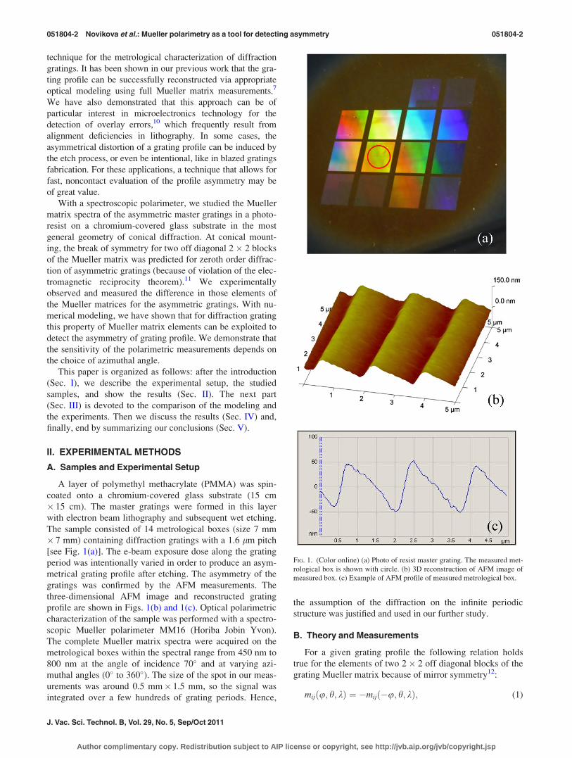
The sample consisted of 14 metrological boxes (size 7 mm
� 7 mm) containing diffraction gratings with a 1.6 lm pitch
[see Fig. 1(a)]. The e-beam exposure dose along the grating
period was intentionally varied in order to produce an asym-
metrical grating profile after etching. The asymmetry of the
gratings was confirmed by the AFM measurements. The
three-dimensional AFM image and reconstructed grating
profile are shown in Figs. 1(b) and 1(c). Optical polarimetric
characterization of the sample was performed with a spectro-
scopic Mueller polarimeter MM16 (Horiba Jobin Yvon).
The complete Mueller matrix spectra were acquired on the
metrological boxes within the spectral range from 450 nm to
800 nm at the angle of incidence 70� and at varying azi-
muthal angles (0� to 360�). The size of the spot in our meas-
urements was around 0.5 mm� 1.5 mm, so the signal was
integrated over a few hundreds of grating periods. Hence,
the assumption of the diffraction on the infinite periodic
structure was justified and used in our further study.
B. Theory and Measurements
For a given grating profile the following relation holds
true for the elements of two 2� 2 off diagonal blocks of the
grating Mueller matrix because of mirror symmetry12:
mijðu; h; kÞ ¼ �mijð�u; h; kÞ; (1)
FIG. 1. (Color online) (a) Photo of resist master grating. The measured met-
rological box is shown with circle. (b) 3D reconstruction of AFM image of
measured box. (c) Example of AFM profile of measured metrological box.
051804-2 Novikova et al.: Mueller polarimetry as a tool for detecting asymmetry 051804-2
J. Vac. Sci. Technol. B, Vol. 29, No. 5, Sep/Oct 2011
Author complimentary copy. Redistribution subject to AIP license or copyright, see http://jvb.aip.org/jvb/copyright.jsp

where / is an azimuthal angle, h is an angle of incidence,
and k is wavelength of the light.
It was shown by Li11 that, at conical mounting, the zeroth
order cross-polarization complex reflection coefficients of
the grating are antisymmetric [r0sp u; h; kð Þ ¼ �r0
ps u; h; kð Þ],provided that the grating is composed of only reciprocal
materials and is invariant under the rotation by 180� about
the normal incidence. This is a direct consequence of the
electromagnetic reciprocity theorem for the zeroth diffracted
order. It leads to the following relations between the ele-
ments of 2� 2 off diagonal blocks of the Mueller matrix:
m13ðu;h;kÞ ¼ �m31ðu;h;kÞ m14ðu;h;kÞ ¼ m41ðu;h;kÞm23ðu;h;kÞ ¼ �m32ðu;h;kÞ m24ðu;h;kÞ ¼ m42ðu;h;kÞ:
(2)
The asymmetry of the diffraction gratings violates the above-
mentioned reciprocity. The absolute values of the transposed
elements of 2� 2 off diagonal blocks of the Mueller matrix
in Eq. (1) change to: mijðu; h; kÞ�� �� 6¼ mjiðu; h; kÞ
�� ��. The pure
conical mounting (u ¼ 690� or u ¼ 90�; 270�) is of particu-
lar interest, because as it follows from Eqs. (1) and (2), the
elements of 2� 2 off diagonal blocks of the Mueller matrix
have to be equal to zero for a symmetric grating profile, while
they can be different from zero for a asymmetric grating
profile. The complete spectral Mueller matrices of the same
metrological box measured at two reciprocal azimuthal con-
figurations (u ¼ 90�; 270�) are plotted in Fig. 2. As shown,
the elements of two off diagonal blocks are different from
zero, as predicted by the theory for the asymmetric grating
profile.
III. MODELING
The acquired spectral Mueller matrices of the gratings,
measured at different azimuthal angles, are fitted with the
parametric model of the grating profile shown in Fig. 3, where
Hgrating is the height of the ridge, L is the top width (CD), and
A and B are left and right slope projections of the trapezoid.
While fitting the measured spectra, we noted overlap of the
neighbor ridges. At that point, we introduced a continuous
resist layer of thickness Hlayer underneath the grating and con-
sequently reduced the A and B values. This reflects the fact
that the chromium surface was not open during the wet etch-
ing of the sample. The direct simulations of spectral Mueller
matrices were performed with the rigorous coupled-wave
analysis (RCWA) algorithm13 and the S-matrix method.14
FIG. 2. (Color online) Measured complete Mueller matrix spectra at two reciprocal azimuthal angles / ¼ 90� (red
line) and / ¼ 270� (blue open circles). All elements of Mueller matrices are normalized by m11 element, which is not
shown here.
FIG. 3. Parametric model of grating profile.
051804-3 Novikova et al.: Mueller polarimetry as a tool for detecting asymmetry 051804-3
JVST B - Microelectronics and Nanometer Structures
Author complimentary copy. Redistribution subject to AIP license or copyright, see http://jvb.aip.org/jvb/copyright.jsp

Figure 4 shows the results of the fit for measurements at azi-
muthal angles from 0� to 90� at every 5� increment.
The standard uncertainties of the estimated parameter val-
ues were calculated as the square roots of the diagonal ele-
ments of the covariance matrix Cij. This matrix is defined as
the inverse of dispersion matrix aij ¼PNk¼1
1=r2k @mðpÞk=��
@pi� @mðpÞk=@pj
� �g, i, j¼ 1,…K, where N is the number of
measured spectral points, rk is the estimated uncertainty of
the measurement, K is the number of floating parameters of
the model (K¼ 4 in our case), p is the vector of model pa-
rameter values, and @mðpÞk=@pi is the derivative of Mueller
matrix elements at the spectral point k with respect to model
parameter pi. We assume that the errors for the raw data are
not statistically correlated and have the same standard devia-
tions equal to the measurement accuracy (0.015).
The variance analysis shows that optimal values of param-
eters of the model (H, L, A, and B) have the smallest errors
for the azimuthal angles u closest to 90� (plane of light inci-
dence is parallel to the grating grooves). The largest parame-
ter errors are for the angles u closest to 0� (plane of light
incidence is perpendicular to the grating grooves). Moreover,
for two parameters A and B, the errors are infinitely large at
u¼ 0� [not shown in Fig. 4(c) and 4(d)] because of very high
parameter correlation at this measurement configuration. Fit-
ting the data acquired at different azimuthal angles (0�–80�)gives no direct evidence of the profile asymmetry [Fig. 4(c)
and 4(d)]. The optimal values of parameters A and B look the
same, given the parameters’ errors. The measurements at azi-
muthal angles close to u¼ 90� reveal the strong asymmetry
of the grating profile with relatively small parameter errors
[see Fig. 4(c) and 4(d)].
To further study this effect, we repeated the measure-
ments and the fit of experimental spectra, varying the azi-
muthal angle u from 0� to 360� by increments of 15�. The
parametric model of gratings was modified according to the
results of the previous fit. The continuous layer of PMMA
resist with a fixed thickness of 33 nm was added to the
model (see Fig. 5).
IV. RESULTS AND DISCUSSION
A. Calculated optimal parameter values
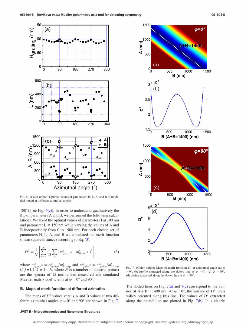
The optimal values of model parameters versus different
azimuthal angles are shown in Fig. 6. The optimal values of
grating height H exhibit periodic behavior with the period of
90� with maximal values at u¼ 0�, 90�, 180�, and 270� (pla-
nar and pure conical configurations) [Fig. 6 (a)]. The optimal
values of L (top width of grating ridge) have two minima at
u¼ 90� and 270�, and vary significantly at other azimuthal
angles [Fig. 6 (b)]. The dependence of the optimal values of A
and B on azimuthal angle is more complex. It should be noted
that at pure conical mounting (u¼ 90� and 270�), parameter
A dips to a minimum value, while parameter B reaches a max-
imum value. At the same time, the values of A and B are
flipped at the angles close to planar diffraction (u¼ 0� andFIG. 4. (Color online) Optimal values of model parameters H, L, A, and B
(see text) at different azimuthal angles.
FIG. 5. Modified parametric model of the grating. The thickness of continu-
ous resist layer under grating is fixed at 33 nm.
051804-4 Novikova et al.: Mueller polarimetry as a tool for detecting asymmetry 051804-4
J. Vac. Sci. Technol. B, Vol. 29, No. 5, Sep/Oct 2011
Author complimentary copy. Redistribution subject to AIP license or copyright, see http://jvb.aip.org/jvb/copyright.jsp
180�) [see Fig. 6(c)]. In order to understand qualitatively the
flip of parameters A and B, we performed the following calcu-
lations. We fixed the optimal values of parameter H at 100 nm
and parameter L at 150 nm while varying the values of A and
B independently from 0 to 1500 nm. For each chosen set of
parameters H, L, A, and B we calculated the merit function
(mean square distance) according to Eq. (3),
D2 ¼ 1
N
XN
k¼1
1
15
Xij
ðmkij;exp � �mk
ij;sim � Þ2
" #; (3)
where mkij;exp� ¼ mk
ij;exp=mk11;exp and mk
ij;sim� ¼ mkij;sim=mk
11;sim
(i, j =1,4, k = 1,..,N, where N is a number of spectral points)
are the spectra of 15 normalized measured and simulated
Mueller matrix coefficients at u¼ 0� and 90�.
B. Maps of merit function at different azimuths
The maps of D2 values versus A and B values at two dif-
ferent azimuthal angles u¼ 0� and 90� are shown in Fig. 7.
The dotted lines on Fig. 7(a) and 7(c) correspond to the val-
ues of AþB¼ 1400 nm. At u¼ 0�, the surface of D2 has a
valley oriented along this line. The values of D2 extracted
along the dotted line are plotted in Fig. 7(b). It is clearly
FIG. 6. (Color online) Optimal values of parameters H, L, A, and B of modi-
fied model at different azimuthal angles.
FIG. 7. (Color online) Maps of merit function D2 at azimuthal angle (a) /¼ 0�, (b) profile extracted along the dotted line at / ¼ 0�, (c) / ¼ 90�,(d) profile extracted along the dotted line at / ¼ 90�.
051804-5 Novikova et al.: Mueller polarimetry as a tool for detecting asymmetry 051804-5
JVST B - Microelectronics and Nanometer Structures
Author complimentary copy. Redistribution subject to AIP license or copyright, see http://jvb.aip.org/jvb/copyright.jsp

shown that the merit function has two equivalent minima at
the points A¼ 200 nm, B¼ 1200 nm and A¼ 1200 nm,
B¼ 200 nm. In the planar configuration, the deviation of the
profile from the symmetric one is visible, but it is impossible
to distinguish between right- (A>B) or left- (A<B) sided
trapezoids. Thus, the flip of A and B values at the measure-
ment configurations close to the planar one can be easily
induced by the measurement noise, which is always present.
Depending on the initial guess, the fit procedure can con-
verge to any of two existing minima of the merit function.
Conversely, at conical mounting (u= 90�) the valley of merit
function transforms into asymmetric one along the dashed
line [see Fig. 7(d)]. The data extracted along the same line
AþB¼ 1400 nm then showed only one global minimum
located at the point A¼ 50 nm, B¼ 1350 nm. At the angles
u close to 90� or 270� the fit procedure always converged to
the same values of A and B (A<B). The asymmetry of the
profile found from the fit of spectral Mueller matrix coeffi-
cients is consistent with AFM measurements of the sample.
At conical mounting, not only the distortion of the symmet-
ric profile can be detected, but the direction of the displace-
ment can be identified.
V. SUMMARY AND CONCLUSIONS
The metrological studies of asymmetric resist gratings
with the pitch of 1.6 lm on chromium-covered glass sub-
strate, used for the fabrication of the master grating in the
nanoimprint fabrication process, were performed with a
spectroscopic Mueller polarimeter at a fixed angle of inci-
dence 70� and varied azimuthal angles (0�<u <360�). The
acquired spectra were fitted with the asymmetric trapezoid
model. From the variance analysis, the smallest parameter
errors are found at the azimuthal angles close to pure conical
mounting (u¼ 90�6 10� or 270�6 10�). Compared to pla-
nar configuration (u¼ 0� or 180�), these results are robust
and less sensitive to the measurement noise. We propose that
grating profile symmetry check should be performed using
polarimetric measurement at azimuthal angles close to coni-
cal mounting, and not those close to planar mounting. It was
experimentally observed and numerically modeled that not
only the distortion of the symmetric profile can be detected
but the direction of the displacement (left or right) can also
be identified provided the Mueller matrix of grating is meas-
ured at conical mounting. This property of Mueller matrices
could be exploited for the unambiguous characterization of
the asymmetry in grating profiles.
ACKNOWLEDGMENT
Funding from Agence nationale de la recherche (ANR)
through the project MuellerFourier is gratefully
acknowledged.
1See: International Technology Roadmap for Semiconductors, http://www.
itrs.net/.2R. G. Dixson, R. A. Allen, W. F. Guthrie, and M. W. Cresswell, J. Vac.
Sci. Technol. B 23, 3028 (2005).3N. G. Orji, T. V. Vorburger, J. Fu, R. G. Dixson, C. V. Nguyen, and
J. Raja, Meas. Sci. Technol. 16, 2147 (2005).4J. J. Hwu. S. Babin, and K. Bay, Proc. SPIE 7638, 76383O (2010).5V. A. Ukraintsev and J. Foucher, Proc. SPIE 7638, 76381C (2010).6R. Alassaad, S. Regonda, L. Tao, S. Pang, and W. Hu, J. Vacuum Sci.
Technol. B 25, 2396 (2007).7T. Novikova, A. De Martino, S. Ben Hatit, and B. Drevillon, Appl. Opt.
45, 3688 (2006).8T. Novikova, A. De Martino, P. Bulkin, Q. Nguyen, B. Drevillon,
V. Popov, and A. Chumakov, Opt. Express 15, 2033 (2007).9D. Goldstein, Polarized Light, 2nd ed. (Marcel Dekker, New York, 2003).
10T. Novikova, A. De Martino, R. Ossikovski, and B. Drevillon, Eur. Phys.
J. Appl. Phys. 31, 63 (2005).11L. Li, Opt. Soc. Am. A 17, 881 (2000).12S. Ben Hatit, M. Foldyna, A. De Martino, and B. Drevillon, Phys. Status
Solidi A 4, 743 (2008).13M. G. Moharam, E. B. Grann, D. A. Pommet, and T. K. Gaylord, J. Opt.
Soc. Am. A 12, 1068 (1995).14L. Li, J. Opt. Soc. Am. A 13, 1024 (1996).
051804-6 Novikova et al.: Mueller polarimetry as a tool for detecting asymmetry 051804-6
J. Vac. Sci. Technol. B, Vol. 29, No. 5, Sep/Oct 2011
Author complimentary copy. Redistribution subject to AIP license or copyright, see http://jvb.aip.org/jvb/copyright.jsp