muaum - Robotron: 2084 · VR1 VR2 VR3 VR4 VR5 VR6 VRi VR8 Fig. 5 o VR1 ... Po fotr adjusting volum...
24
muaum AND INSTRUCTIONS PARTS CATALOG TAITO CORPORATION 0 0 0 % 0 I 4 0 0 0 ? 0 0 0 s 0 0 0 0 0 0 0 0 t 0 0 0 0 i0
Transcript of muaum - Robotron: 2084 · VR1 VR2 VR3 VR4 VR5 VR6 VRi VR8 Fig. 5 o VR1 ... Po fotr adjusting volum...

muaum
A N D I N S T R U C T I O N S
P A R T S C A T A L O G
T A I T O C O R P O R A T I O N
0 0 0
% 0 I 4 0 0 0
? 0 0 0 s 0 0 0
0 0
0 0 0
t 0 0 0 0 i0

. Name of Part (See Fig. 1 and 2)
T i t l e Glass 2-Player S t a r t Button
Fig. 1
Back Door
Fig . 2
1

!. T r a n s p o r t a t i o n and I n s t a l l a t i o n
o Avoid rough handling i n t r a n s p o r t a t i o n ; the p i c t u r e tube i s f r a g i l e .
o T a i t o "SPACE INVAtJERS PART IE " i s f o r indoor use.
o I n s t a l l the machine indoor only.
o Do not i n s t a l l the machine outdoor.
2

o I n s t a l l the machine on a f l a t - s u r f a c e d f l o o r and provide s u i t a b l e space i n f r o n t of the machine.
LZL (F l o o r )
^ ( - 5
o I n case of i n s t a l l a t i o n i n l o c a t i o n w i t h v i b r a t i o n , f i x the machine by the use o f anchor b o l t s and wire ropes as shown below.
Wire Ropes
o Do not i n s t a l l the machine i n dangerous places viewed from the angle of d i s a s t e r p r e v e n t i o n .
(Emergency E x i t ) F i r e Alarm
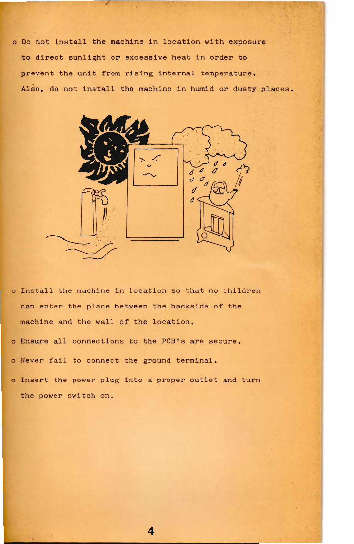
o Do not i n s t a l l the machine i n l o c a t i o n w i t h exposure to d i r e c t s u n l i g h t or excessive heat i n order t o prevent the u n i t from r i s i n g i n t e r n a l temperature. Also, do not i n s t a l l the machine i n humid or dusty places.
o I n s t a l l the machine i n l o c a t i o n so t h a t no c h i l d r e n can enter the place between the backside o f the machine and the w a l l o f the l o c a t i o n .
o Ensure a l l connections to the PCB's are secure.
o Never f a i l to connect the ground t e r m i n a l .
o I n s e r t the power plug i n t o a proper o u t l e t and t u r n the power switch on.
4

I . Handling Note and Warning
Note:
o Erroneous p i c t u r e may appear on the screen when the machine i s f i r s t switched on. t h i s i s t y p i c a l o f the CPU c i r c u i t r y , and w i l l c o r r e c t i t s e l f a u t o m a t i c a l l y when the power swit c h i s o f f and on.
o No p i c t u r e may appear on the screen f o r a wh i l e when the machine i s switched on at a subzero temperature i n the l o c a t i o n . This i s also t y p i c a l o f the s o l i d -s t a t e c i r c u i t r y .
Warning:
o T a i t o "SPACE INVADERS PART U " uses a CPU and the l a t e s t s o l i d - s t a t e c i r c u i t r y f o r long l i f e , however, as w i t h s o p h i s t i c a t e d e l e c t r o n i c equipment c e r t a i n precautions must be observed t o acoid damage.
(1) Do not attempt t o service w i t h o r d i n a r y t e s t i n g equipment, since the i n t e r n a l voltage o f the t e s t i n g equipment may cause damage to the c i r c u i t r y .
(2) Never connect or disconnect any o f the s o l i d - s t a t e modules wh i l e the power i s on.
. Routine Maintenance
o Because o f the s o l i d - s t a t e e l e c t r o n i c c i r c u i t r y , t h i s machine should r e q u i r e very l i t t l e maintenance and only occasional adjustments, however, i t i s necessary to take measures t o insure i t s d a i l y s a f e t y .
5

I P laying I n s t r u c t i o n o One or two pl a y e r s . o I n s e r t C o i n ( s ) .
1 Coin - 1 play (3 l a s e r bases ... Adjustable) 2 c o i n - 2 plays ( o r 2 player game)
o Select one or two player game. o As the " a t t a c k i n g sound" i s heard, invaders appear on
the screen. Also, a l a s e r base and f o u r f o r t r e s s e s appear on the lower side of the screen.
o To move the l a s e r base l e f t or r i g h t , move the c o n t r o l l e v e r .
o To f i r e l a s e r , push the f i r e b u t t o n . o I n two player mode, the play a l t e r n a t e s between the two, o Scoring:
500 p t s .
? ? ?
§^£h 3 0 p t s *
i f t i 2 0 p t s -10 p t s .
Functional D e s c r i p t i o n o f Game: o Invaders advance step by against the l a s e r base as
they move l e f t and r i g h t .
o Fortresses are gr a d u a l l y destroyed by the a t t a c k o f invaders. They are also destroyed by l a s e r .
o As the number of invaders destroyed, they move f a s t . o A MYSTERY-UFO h i t gives the player mystery score (50,
100, 150, or 300 p o i n t s ) .
o When score reaches 1,500 p o i n t s ( a d j u s t a b l e ) , a bonus l a s e r base appears "beep" sounds.
6

o UFO w i l l randomly drop invaders. o When a invader i s h i t , i t w i l l be sometimes d i v i d e d i n t o
two. o Game ends when a l l lasen bases are h i t by invader missies
or when Invaders overrun the base. o High-score's name can be r e g i s t e r e d on the screen as f o l l o w s :
(Any d i s l i k e - sentence can be canceled by using the cancel b u t t o n . However, the high score can not rubbed out.)
(1) The alphabets ("A"-"Z"), "RUB", and "END" w i l l be displayed on the screen. By moving the c o n t r l l e v e r , move the red und e r l i n e t o the alphabet one by one so t h a t the h i g h -scorer 1s.name can be s p e l l e d .
(2) An alphabet on the red un d e r l i n e can be r e s i s t e r e d at a time on the screen by pushing the f i r e b u t t o n "RUB" ... I f any wrong alphabet has been r e g i s t e r e d , move
"END" ... When f i n i s h i n g the high-scorer's name r e g i s t r a t i o n
(3) The high-scorer's name r e g i s t e r can be made w i t h i n one and h a l f minutes. A f t e r one and h a l f minutes passed, the r e g i s t r a t i o n w i l l be a u t o m a l i c a l l y stopped. ( I n t o t a l , ten alphabets can be r e g i s t e r e d . )
Method:
•the red un d e r l i n e t o the word "RUB", and push the f i r e b u t t o n so t h a t the alphabet w i l l be canceled.
move the red un d e r l i n e t o the word "END" and push the f i r e b u t t o n .

Adjustments on Power Supply P.C Board (See F i g . 4)
Caution: The l i n e voltages should be set w i t h i n the l i m i t s . F a i l u r e to do so may r e s u l t i n d e s t r u c t i o n o f the I.C's.
o To check the output v o l t a g e s , measure them on the G-connector or the T-connector. (See the cable block diagram, AAR00190 i n t h i s manual.)
© + 5 V V R
A S -v o (g>) + 1 2 V V R
@ - 1 2 V V R
F i g . 4
o -12V VR ... Pot f o r a d j u s t i n g -12V l i n e voltage (Adjustable range: -12V 15V DC) Set approx. -12V.
o + 5V VR ... Pot f o r a d j u s t i n g 5V l i n e voltage (Adjustable range: 5V - 6V DC) Set approx. +5V.
o +12V VR Pot f o r a d j u s t i n g 12V l i n e voltage (Adjustable range: 12V - 15V DC) Set approx. -5V.
8

Adjustments on Game & Sound P.C Board (See F i g . 5 and Table 1)
To increase the sound, t u r n each pot(VRl - VR8) as show below.
ON 1 0 s w
n Q c p CP m CD CD.
n a A a a a & ̂ c VR1 V R 2 VR3 VR4 V R 5 V R 6 V R i
VR8
F i g . 5
o VR1 ... Pot f o r a d j u s t i n g volume o f UFO.
o VR2 ... Pot f o r a d j u s t i n g volume of l a s e r base when f i r i n g .
o VR3 ... Pot f o r a d j u s t i n g volume of l a s e r base when destroyed
o VR4 ... Pot f o r a d j u s t i n g volume o f invaders when destroyed.
o VR5 ... Pot f o r a d j u s t i n g volume of "beep" when conus i s awarded.
o VR6 ... Pot f o r a d j u s t i n g volume o f invaders when advancing.
o VR7 ... Pot f o r a d j u s t i n g volume o f UFO when destryed.
o VR8 ... Pot f o r a d j u s t i n g t o t a l sound volume.
9

ange-over f o r DIP Switch:
SW1 ... Switch f o r changing-over the number o f la s e r bases.
WS1 Laser Bases ON 3 OFF 4
Table 1
The number of las e r bases i s preset at "3" at the f a c t o r y .
SW2 ... Switch f o r r o t a t i n g images on the screen. When t h i s s witch i s set at "ON" p o s i t i o n , the images on the screen w i l l be r o t a t e l . This switch should be always set at "OFF" p o s i t i o n .
SW3 ... Switch f o r a d j u s t i n g the s o l i d - s t a t e modules. This switch i s f o r the f a c t o r y adjustaments, and should be set at "OFF" p o s i t i o n .
SW4 ... Switch f o r checking When the switch i s set at "OFF" p o s i t i o n , the cheching can be done. Normally, t h i s s witch i s to be set at "ON" p o s i t i o n .
SW5, SW6, SW7 ... Switch f o r a d j u s t i n g the s o l i d - s t a t e modules. These switch are f o r the f a c t o r y adjustments, and should be always set at "OFF" p o s i t i o n .
SW8 ... Switch f o r d i s p l a y i n g the p l a y - p r i c i n g (1 COIN 1 PLAYER, 2 COIN 2 PLAYERS) on the screen. When the switch i s set at "ON" p o s i t i o n , the p l a y - p r i c i n g w i l l be displayed.
10
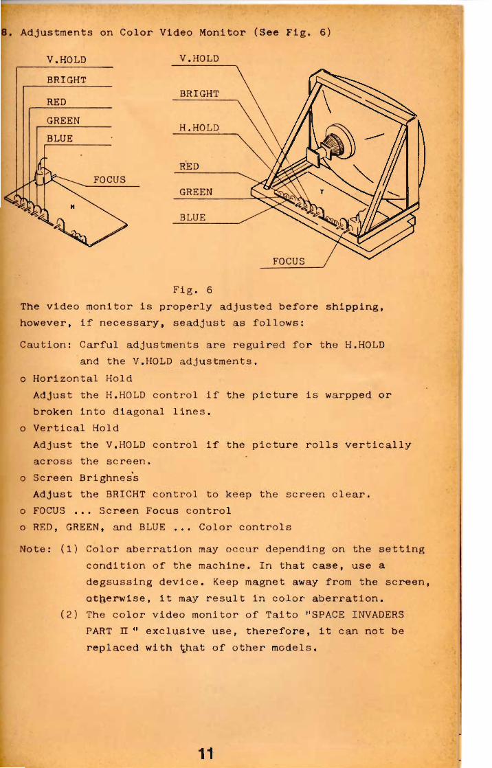
. Adjustments on Color Video Monitor (See F i g . 6)
V.HOLD V.HOLD
Fig. 6 The video monitor i s p r o p e r l y adjusted before shipping, however, i f necessary, seadjust as f o l l o w s : Caution: C a r f u l adjustments are r e g u i r e d f o r the H.HOLD
and the V.HOLD adjustments, o H o r i z o n t a l Hold
Adjust the H.HOLD c o n t r o l i f the p i c t u r e i s warpped or broken i n t o diagonal l i n e s ,
o V e r t i c a l Hold Adjust the V.HOLD c o n t r o l i f the p i c t u r e r o l l s v e r t i c a l l y across the screen,
o Screen Brighness Adjust the BRICHT c o n t r o l to keep the screen c l e a r ,
o FOCUS ... Screen Focus c o n t r o l o RED, GREEN, and BLUE ... Color c o n t r o l s Note: (1) Color a b e r r a t i o n may occur depending on the s e t t i n g
c o n d i t i o n of the machine. I n t h a t case, use a degsussing device. Keep magnet away from the screen, otherwise, i t may r e s u l t i n c o l o r a b e r r a t i o n .
(2) The c o l o r video monitor o f Tai t o "SPACE INVADERS PART H " exclusive use, t h e r e f o r e , i t can not be replaced w i t h t^hat o f other models.
11
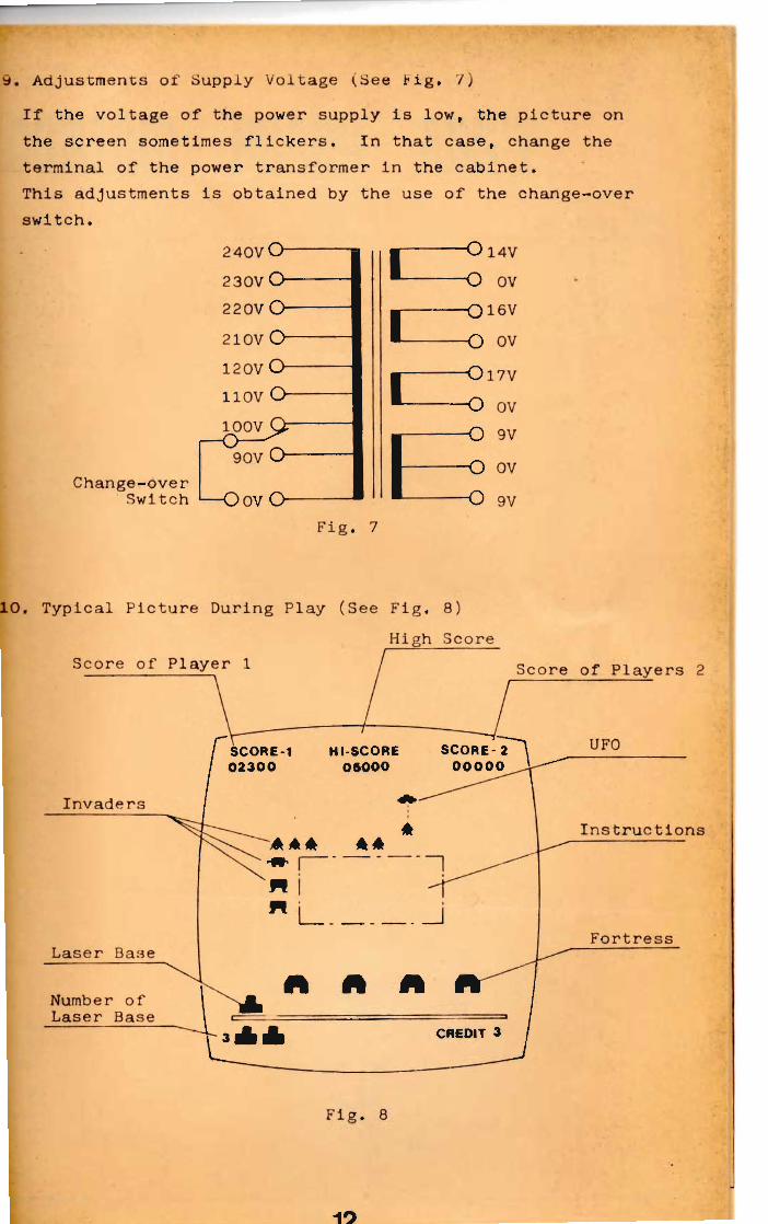
. Adjustments of Supply Voltage (See t i g . 7) I f the voltage of the power supply i s low, the p i c t u r e on the screen sometimes f l i c k e r s . I n t h a t case, change the term i n a l of the power transformer i n the cabinet. This adjustments i s obtained by the use o f the change-over switch.
240VO 230V O 220V O 210V O 120V O
Change-over Switch 1—OOV O
[
[
[
-O 14V
O ov - Q 1 6 V
-O ov -Ol7V O ov -O 9V -O ov O 9V
Fig. 7
. Typical P i c t u r e During Play (See Fi g . 8) High Score
Fig . 8
19

CONTROL DOARD A S S Y SEE PAGE 17
1 - - O
13

IIDEO AND CABINET ASS'Y SEE PAGES 18,19
14

15

FRONT DOOR AND COIN MECHANISM A S S Y
SEE PAGES 20,21
•

I
C O N T O B O L BOA K i ) A S S ' Y
P a r t M
BPOfl0 0 0 BWO20 0 0 AAO19 5 3
BPOs 0 0 0 AAO19 5 3 TR09 0 01 TR0 9 0 0 1 AFO3 0 0 02 BV07 0 0 0 AAOl95 « L VO 9 0 0 0 LVO10 0 0 WNO 3 0 0 0 8V09 0 0 2 BV07 0 0 0 WNO 3 0 0 0 SVO3000 SVO2000 WT05 0 0 0 WTO30 0 0 SVO300 0 AAO3 2 5 3 AAOl9 5 0 SVO30 0 0 BPO3 0 0 0 AAO19 3 0 AA05 25 3 RM O3 0 0 0 AAO16 5 5 RMO30 0 0
D e i c r i p t l o u C o l o r B a l l C o n t r o l S h a f t P u s h B 0 t l 0 a Rod S p r l a g (A)
P u s h B a t t o a H o u s i n g R o d P u i h Bo t t oa P u s h B e t t o n H o m i n g W h i t o C • r no r Ed g • F r o n t P a n o l C o l o r P l a t a V i d o o M a s k C o n t r o l B o a r d L o o k P l a t o S I i d o P l a t o I n s t r u c t i o n C a r d Cam S t o p p o r B r a o k o t S h a f t P l a t o S p r i ag Wa s h 0 r S p r i n g B r a o k o t M i e r 0 S w l t ah I n s u l a t o r T j pa—V S w i t c h Ba s a P u s h S w i t oh B r a o k o t I n s u l a t o r T j p o - V M i 0 r e S w i t ah V L - i l L H o o k S u p p o r C r a m p C—137 S t o p P l a t a
17
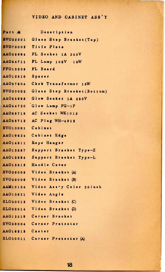
VIDEO AND CABINET ASS'Y
P a r t M, D o a a r i p t i o n BVO3 0 0 0 1 Gl aa a S t a p B r a e k o t ( T o p ) BVO7 00 02 T i i l 1 a P l a t a A A O 5 1 6 t 4 F L S o c k i t 1A 250V AAO 5 4 7 1 1 F L Lamp 10 0V l &W FFOl 0 0 0 5 F L B a a r d AAOl2 5 10 S p a e a r AAO 5 7 6 0 4 Chok T r a a s f o rmor l sW BV0 30 0 0 2 G l a s a S t o p B r a c k e t ( B o t t o m ) AAO 5 5 6 9 5 Glow S o c k e t l A 250V AAO5 4 7 20 Glow Lamp FG-lP AAO 5 6 7 1 6 AC S o c k a t WKl0 12 AAO5 5 7 1 3 AC P l u g WH-4 012 BVOl0001 Cab i no t AAO19 6 2 4 Cab i n o t Edga AAOl4 5 11 Ro po Ha ng o r AAOl3 5 3 7 S u p p a r t B r a e k o t T j p e - Z AAOl 3 5 8 4 S u p p o r t B r a a k o t T y p o — L AAOl3612 Ha ad 1 o C o v o r SVO3 0 0 0 5 V i do o B r aake t (A) SV0 3 0 0 0 6 V i d o o B r a a k a t (B) AAMi0 104 V i d o 0 A t a ' j C o l o r 20 i n t h AAOl3 6 2 1 V i d o o Ang1 a SL03 0 0 1 3 V i . do o B r a o k o t (C) SL O 3 0 0 1 4 Vi« do a B r a a k a t (D) AAOl3 5 19 Ca r n ar B r a o k o t SVO30 0 04 Ca r n ar P r a t o o t a r A A O l 6 5 1 3 Ca i t a r SLO30 0 1 1 Ca r Q ar P r o t e c t o r (A)
18

•AO13 i 1 0 L o o k P l a t o AAO13 5 6 9 L o o k G i r d (B) A A O l 6 6 8 1 S e r v i c e L e e k yfe7 9 0 0 EPOS 0 010 Vo n t i1»t o r AAO1 8 5 2 S B o o k D o o r S t o p p o r AAO16 8 4 6 L o o k & K•7 AAO26 6 12 C i i h Box D o o r AAOl 3 5 82 L o o k P l o t s AAO28 6 06 C a s h C a a a AAO2 8 5 0 7 C a s h B a a A A O l 3 6 8 0 C a s h Box G o l d . (B) AAO13 5 7 0 C a s h B o x G u i d e (A) AAO2 5 5 1 0
• C a i n C h u t a
A A O l 3 6 09 P l a t o A A 0 5 1 7 17 C a u a t a r DC 6V A A O l 3 6 08 C o u n t e r B r o c k e t
PRINTED BOARD AND REGULATOR ASS
P a r t M, D a s o r i p t i o n AAO19 5 2 7 P. C B o a r d G u i d e (A) TUO2 00 0 1 S h a f t BVK00 002 B. V-Ma i n-P. C. B o s r d A s s ' y AAO55 9 4 9 AMPLEAP C o n n o o t o r 18P CVO30 02 3 S t o p B r a o k o t WTO9 0 0 0S P. C. B o a r d G u i d e (B) AAM50 0 12 C o u n t e r D r i v e P. C. B o a r d A n '7 AAO65 7 2 0 P r i n t C o n n a o t a r i o P AAO13 6 6 6 C a n n o a t a r B r a a k a t AAO19 6 4 2 Sw i t o h C o r o r AAOS 2 5 0 1 T a g g l a S w i t c h S-301 •A06 2 6 32 AC C a r d & P l a g A s a ' 7
19

AAOl 5 714 F a a e H o l d e r S-N2066
AAO 5 * 102 E a r t h T e r m i n a l T - 3 7 5
AAOl 1 194 S w i t ah Box
•AMtO 0 0 1 Power S u p p l y P. C. B o a r d
AAOl 9 127 P C B a a r d G a i d a (A)
AAOl 9 128 P. C B a a r d Ga i d a (B)
AAOl S 5 12 P u a o h i ag Ma t a 1
AAOl 9 5 21 No t
AAT7 1 0 1 1 S p e a k e r 8fl 2 OW 1 6cm
AAOl 5 8 0 8 F a a e H o l d o r F 3 3 2 1 4P
AAO t 7 512 T r a a 1 f 0 rmer
A A T l 4 026 R e c t i f i e r 1 2 C 2 O
AAT 4 1 166 ' C a p o i t a r i f l L A S N - 2 2 0 0
AAO 5 f 768 AC S o o k e t S—15 20
AAOl a 599 S a o k o t Box
AAO 5 2 635 T a g g l a S w U e h S-2A
BWOlO 0 0 8 T r a n t f o r m o r B o a r d
AA05 7 6 7 3 T r a n s f o r m e r
FBONT DOOR AND COIN MECHANISM ASS'Y
P a r t M D o a e r i p t i o a
AAO 2 6 5 10 D a o r F r a m e
AAO 2 9 5 0 8 P r i oa C a r d f a r ¥ 1 0 0
AAO 5 4 7 0 4 P i l o t Lamp 1 2 V 150mA
AAO 5 5 698 V i a j l S o o k a t
AAO 2 1633 C a i n E n t r y P l a t a f a r ¥ l 0 0
AAO 2 16 30 C o i n S h i e l d P l a t o
AAOl 6 5 66 S e r v i c e L o o k A7 900
AAOl 6 6 60 S e r v i e a K e j jfc7 9 0 0
AAOl 7 7 06 T A I T O Name P l a t a
AAO 2 66 1 1 Re j e e t 0 r Da a r
L 20

iOl • 522 L O§ 5 7 8 9 LO 5 5 5 8 1 iOl 3 5 2 7 L 0 5 5 58 2 iOfi I 7 9 0
AAOl35 7 8 AAO 2 5 5 0 8 AAO2 6 5 07 AA06 8 717 AAOl35 7 7 AAO2 7 5 04 AAO15 5 0 4 AAO 5 2 5 3 1 AAO13 5 5 7 AAO13 5 5 4 AA02 3 3 0 1 AAO2 5 5 0 3 AAO19 5 0 2 AAO 5 2 5 1 2 AAO 5 3 5 0 1 AA02 2 5 0 3
C • T • r P l i i i M a t e - N - L o k P l u g P i a M a t e - N - L e k C a p 9P S e e k e t B r a a k a t M a t a - N - L a k P l u g 9P M a t e - N - L a k S a k a t P i n L a k P l a t a C a i n G u i d e (B) C a i n Gu i da (A) T i 1 t S w i t ah L o o k G a r d C a n c e l Red
C a n c e l H o l d e r S p r i n g P i s h B a t t e n S w i t c h V L i l L C a n c e l L e v e r R e j e c t o r B r a c k e t R a j e e t e r H e l d e r M S C a i n G a i d a I n s u l a t o r C-5G.T7pe-3 M i c r o S w i t e h C-5G3-3 A e t u a t o r C A A - l Ra j e a t a r f a r ¥100
21

AA
R001
M
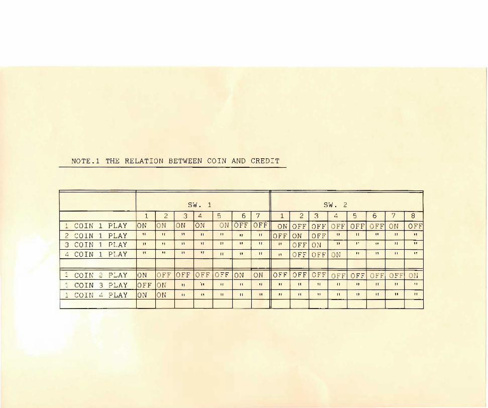
NOTE
.l THE
RELA
TION BETWEEN
COIN A
ND CR
EDIT
SW.
1 SW.
2 1
2 3
4 5
6 7
1 2
3 4
5 6
7 8
1 CO
IN 1
PLAY
ON
ON
ON
ON
ON O
FF O
FF
ON O
FF O
FF O
FF O
FF O
FF o
n OFF
2 CO
IN 1
PLAY
ii
II II
n II
II
II
OFF
ON
OFF
ii 11
II
ti
It
3 CO
IN 1
PLAY
n II
11
it
it
II
II
II
OFF
ON
II
I'
M
11
4 CO
IN 1 PLAY
II
11
II
11
it
it
11
II
OFF
OFF
ON
II
II
tl
1 CO
IN 2
PLAY
ON
OFF
OFF
OFF
OFF
ON
ON
OFF
OFF
OFF
OFF
OFF
OFF
OFF
ON
1 CO
IN 3
PLAY OFF
ON
II
'ti
II
II
II
it
n it
II
II
II
it
11
1 CO
IN 4
PLAY
ON
ON
II
II
II
II
II
it
II
n it
II
n II
11