MTP 2-2-608 Braking, Wheeled Vehicles
27
I Materiel Test Procedure 2-2-608 15 January 1971 Aberdeen Proving Ground 'DDC BRAKING, WHEELED VEHICLES UL L j ~c r 1. OBJECTIVE This Materiel Test Procedure provides Rtandardized tests for' j evaluating wheeled vehicle braking systems. - 2. BACKGROUND Braking is a basic element of all automotive testing and, be- cause of its association with personnel safety, dictates the requirement for particularly thorough testing and evaluation of wheeled vehicle braking oystem to assure dependability and effectiveness under all conditions. Major factors considered in the evaluation of wheeled vehicle braking systems are stopping and holding ability, vehicle control when applying brakes, and individual braking system component endurance under , various operating conditions. I, ( Brake testing involves not only tests )n straght, level roads but tests on mountain highways that have log. grades r.equiring anY brake applications as well. F6r such tests a apecific public highway I Pen- sylvania has been authorized. Brake tests aIlso include water Amerssin of the vehicle in a fording basin. 3. REQUIRED E!UIPMENT 3.1 TEST COURSES Required test courses are as follows: a. A straight, level, paved road with lane width of not less than 12 feat. b. Longitudinal slopes ranging from 5 to 60 percent grade and of sufficient length to accoiodate military vehidlei of various dimensions. c. A fording basin of sufficient length and depth to completely Z submerge the service brake assemblies of all sizes of military "heeled vehicles. d. Mountain highway test course (App. A). e. A downhill roadway ranging from 9 to 11 perent grade for a distance of approximately 2 miles with a reasonabLy level -iiiificte at the bottom of the grade of sufficient length to permit a 40 mph brake stop. (_ *Supersedes Interim Pamphlet 60-71. - o I I FRmAc by RVICE _ p2 - NATIONAL TECHNICAL -1- DistributionUnlimited____ INFORMATION SERVICE 1k13t6 Swkws" .1 =M223
description
testing
Transcript of MTP 2-2-608 Braking, Wheeled Vehicles
I
Materiel Test Procedure 2-2-60815 January 1971 Aberdeen Proving Ground'DDC
BRAKING, WHEELED VEHICLES UL L j ~c
r 1. OBJECTIVE
This Materiel Test Procedure provides Rtandardized tests for'j evaluating wheeled vehicle braking systems.
- 2. BACKGROUND
Braking is a basic element of all automotive testing and, be-cause of its association with personnel safety, dictates the requirementfor particularly thorough testing and evaluation of wheeled vehicle brakingoystem to assure dependability and effectiveness under all conditions.
Major factors considered in the evaluation of wheeled vehiclebraking systems are stopping and holding ability, vehicle control whenapplying brakes, and individual braking system component endurance under
, various operating conditions.
I, ( Brake testing involves not only tests )n straght, level roadsbut tests on mountain highways that have log. grades r.equiring anY brake
applications as well. F6r such tests a apecific public highway I Pen-sylvania has been authorized. Brake tests aIlso include water Amerssin ofthe vehicle in a fording basin.
3. REQUIRED E!UIPMENT
3.1 TEST COURSES
Required test courses are as follows:
a. A straight, level, paved road with lane width of not lessthan 12 feat.
b. Longitudinal slopes ranging from 5 to 60 percent grade and ofsufficient length to accoiodate military vehidlei of various dimensions.
c. A fording basin of sufficient length and depth to completelyZ submerge the service brake assemblies of all sizes of military "heeled
vehicles.d. Mountain highway test course (App. A).e. A downhill roadway ranging from 9 to 11 perent grade for a
distance of approximately 2 miles with a reasonabLy level -iiiificte at thebottom of the grade of sufficient length to permit a 40 mph brake stop.
(_ *Supersedes Interim Pamphlet 60-71. - o I
I FRmAc by RVICE _ p2 -NATIONAL TECHNICAL -1- DistributionUnlimited____
INFORMATION SERVICE 1k13t6Swkws" .1 =M223
15 January 1971
3.2 TEST INSTRUMERTATIOIN
Instrumentation required to colleet brake tzd_ dat& _s asfollows:
a, A fifth wheel equipped with speedometer and pousometer.
b. Hydraulic pressure gauge wtti a bleeder screw in tbe bourdontube.
c. Air pressure gauge.
d. Decelerometer (U-tube type).
e. Pedal travel gauge.
f. Pedal effort gauge.
g. Brake application counter.
h. Tezperature indicating rotentiometer.
i. Thermocouples imbedded in brake friction waterial.
3.3 SPECIALIZED SHOP EQUIPMENT T)Specialized ahop equlpment and instrumentation requixed for
vehicle preparation and post-test inspection are as follows:
a. Micrometer calipers (inside, outside, and dial typcs).
b. Surface finish gusges.
c. Torque wrench.
d. Brake shoe turntable.
e. Feeler gauge stock.
f. Tire pressure gauge.
4. REFEENES
i.. USATECOM Regulation 385-6, Verification of Safety of MaterialDuria Testing.
B. Brake Sysvnd Road Test Code - Truck and Bus, SAE J786.C. MML Standard S-6-66, Human Factors EngineerLng Design
Standard for 'Aheeled Vehicles.D. MP 2-2-506, Durability Testing of Wheeled Vehicles.E. M!P 2-2-508, Safety Evaluatfon (Automotive).
-2-
MTP 2-2-60815 January 1971
F. MTP 2-2-816, High and Low Temperature Tests.G. MTP 2-2-650, Cold Starting and Warmup.H. AR 385-55, Prevention of Motor Vehicle Accidents.
5. SCOPE
5.1 SUMMARY
This MTP describes specific rest phases pertinent to the eval-uation of wheeled vehicle braking systems, as follows:
a. Safety evaluation (par. 6.2.1).
b. Brake burnish (par. 6.2.2.1).
C. Brake holding ability (par. 6.2.22).
d. Brake stopping ability (par. 6.2.2.3).
e. Brake recovery after immersicn in water (par. 6.2.2.4).
f. Trailer breckaway holding ability (par. 6.2.2.5).
g. Maxi mm safe braking speed (par. 6.2.2.6).
h,. Brake actuation and release time (par. 6.2.2.7).
i. Pedal effort (par. 6.2.2.8).
J. Low temperature effects (par. 6.2.2.9).
k. Brake fade on motntain highway (par. 6.2.3.1).
1. High temperature eiidurance on mountain highway (par. 6.2.3.2).
m. Brake endurance and wear (par. 6.2.4).
5.2 LIMITATIONS
This MTP is applicable only to wheeled type vehicles designedfor highway operation.
Vehicles designed specifically for off-highway operation that donot pozass a maximm vehicle speed capability of at least 40 mph will beconsidered on an individual basis. Specific test parameters and criteriawill be provided in plans of test prepared for each peculiar vehicle design.
4qAluation of vehicle retarding systems other than the installedfoundation service braking systems will be considered in a separate MTP.
-3-
"
.si
MTP 2-2-60815 January 1971
6. PROCEDURES
6.1 PREPARATION FOR TEST
6.1.1 Preparation of Test Vehicle and Instrumentation
The vehicle power train, braking, steering, and electricalsystems are prepared for optimum operation..
Proper vehicle weight distribution, lubrication, and tire in-flation pressures are assred.
For mountain nighway .brake tests a yellow and black diagonallystriped signboard is mounted at the rear of the vehicle, displaying 6-inch-diameter stoplights and turning signals,
All instruments are calibrated before and after a test and, ifaecessary, during the test.
6.1.2 Restrictions
Tests are not conducted at night, durin inclement weather, incongested traffic, or when the road surface way intioduqce a L.zatd to thetest vehicle or other traffic on the raQ4. _Dry, un_-oaxuted surfaces are
used unless the test plan introduces a opeciffi requirent. oc&t safety (:1and operating procedures will be carefully followed.
6 2 TEST CONDUCT
6.2.1 Safety Evaluation , -
Prior, to the conduct of other wheed vehicle braking syster.tests, tests wili be conducted to acCumulate di a on A" c t6ba(_ a re-comendation for, the issuance ofa eafety release (USA2ECO Reg. 385-6).
A safety evaluation of tie vehicle braking yate3 will consistof the following performance tests:
a. Brake burnish (par. 6.2.2.1).
b. Holding abillty (par. 6.2Y2.2).
c. Stopping ability (par. 6.2.2.3).
d. Brake. recoveri after' "ersioh in wate t r. 6.2.2.4).
e. Trailer bireakaway holdiig ability I(par. 6,2.2.5).
f. Dtervinatioa of the ma~iizm safe bed for k pedaleffort braking (p r. 6.2.2.6).s
-4-
-- 1'TI? 2-2-60815 January 1971
Tests performed during the safety evaluation usually will notrequire duplication during the other test phases; safety observations arecontinued, however, through all phases of brake testing.
Criteria for safe performance are described in the following
paragraphs devoted to specific performance tent phases.
6.2.2 Performance Tests
Brake performance will be evaluated in terms of adequacy of thevehicle braking system to perform at the required level for each test phase.
6.2.2.1 Brake Burnish
Friction material burnishing is accompli.'ed by either tbe burnishprocedure of SAE J786 or the procedure outlined in Appeno!'x B.
The criterion for frIccion .material burnishing is that not lessthan 80 percent of the f7riction material surface area be in contact with theswept area of the kctatI4 brake member (drum or disk).
6.2.2.2 Brake lilding A!-ility'
The vehicle is parked on dry, paved, longitudinal slopes in bothascending and descending attitudes. Service and parking brake systems areengaged individually to assure their individual capability to hold thevehicle sta~tidnark.
The Ic~terion for brake holding ability for both service andparking brake systems of wheeled vehicles is that each system, independentof the other, hold the vehicle stationary in both ascending and descendingattitudes on the minm longitudinal slope over which the vehicle is re-quired to operate.
6.2.2.3 Brake -St1Pping Ability
Brake stopping distances are ottained from 20 and 40 mph andfrom additional road ,peeds if sm cifically requested. Stopping distancesare measured over the, iip pre range up to the point of wheel locking.
Data c6il~ted "iil' include road speed, stopping distance, deceleration rate,
iqpt prese, whel lokif$ig d Vehicle slw. Brake drum temperaturesshould not exceed 250i, or uoher-ise as specified, during these tests. Forelectrical braking systems, Vltaje and current measurements will be recordedin place of input pressures. These tests will be conducted on a level, hard-surfaced roadway with the vehicle at curb *dight and at its rated payloadcondition.
The criteria for bi]ae stopping ability arei as follows:'
o)
H.!TP 2-2-60815 JanAry 1971
a. Wheeled vehicles of gross vehicle weights up to and in-cluding 50,000 pounds will be capable of making a straight line full stopfrom a road speed of 20 mph within a distance. of 30 feet; they will be capa-ble of making a full stop from a vehicle speed of not less than 40 mph at anaverage deceleration rate of 14.4 ft/sec 2 .
b. Wheeled vehicles of gross vehicle weights exceeding 50,000pounds will be capable of making a straight line full utop from a road speedof 20 mph within a distance of 40 feet; they will be capable of making a fullstop from a vehicle speed of not less than 40 mph at an average decelerationrate of 11 ft/sec2 .
c. During all brake stops, vehicle slew shall not exceed thelimits of a roadway lane width equal to 1-1/2 times the overall width cf thetest vehicle.
6.2.2.4 Brake Recovery after Immersion in Water
Wheeled vehicle braking systems will be completdly submerged inwater for a period of 15 to 30 minutes. After immersion, recovery is'ddter-mined by making brake applications from a road speed of 20 mph at a Ore-selected input pressure at 1-minute intervals. Data requLred will includetime, road speed, number of applications, input pressure, de.eliration rate,and distance traveled. Results will be compared to the dry brake performancepreviously established for the vehkle.
The criterion for brake recoiery is t0ai after iiemrsi6n 'in 'water for a period of 15 to 30 minutes, brake stopping ability shall haveachieved cozplete recovery after 10 brake applications over a period of 12minutes.
i 6.2.2.5 Trailer Breakaway Wold-ifg Akilty'
This test phase will be performed in both ascendigg and des-cending attitudes on paved, longitudinal slopes. The trailers will be parkedon the grade and brake lines disconnected to idtuate the rea Vay feature.Local safety regulations will be followed.
Th6 diitrion for traildt brtalis h ldi i ty is that thesafety Brake featire '"d dapable of hol ing t avehicle stdtioniry in bothasdendi d d iecnding iititdes on the W*Ii slope .er which thevehicle is desiged to operate o" a riodd o! 30 -imtds,' The maxiim -giadewill be desijaied in ° the plan of t6at-u f ec pedifid veiidle.
6.2.2.6 Maximum Pedal Effort Brak'.& jMaximur pedal effort brake stops will be made in the forward
vehicle direction of a dry, level, paved surface at &-mph road speed in-crements over a speed range span of 20 mph tO v eicle" speed (or tothe highest speed where safe maximum pedal effort braking can be achieved)
-6-
1) 15 January 1971
and in the reverse vehicle direction at a road speed of 5 mph. Data re-crrled will include road speed, stopping distance, deceleration rate, wheellocking, and vehicle slew; and data obtained by inspection of wheel, brake,and :iuspension system components.
For maximum pedal effort braking, wheeled vehicles must be capa-ible of making maximum pedal effort brake stops in both forward and reverseEI directions without damage to the brake, wheel, or suspension systems as
follows:
a. Reverse direction - at road speeds up to 5 mph.
b. Forward direction - at road speeds up to 50 mph (essential).- at road speeds up to maximum vehicle
speed (desirablA).
NOTE: If maximum veicle speed is less than 50 mph, a roadspeed test at maximum vehicle speed will be consideredessential.
The criterion for maximum safe speed at maximum pedal effort isthat vehicle slew shall not exceed the limits of a roadway lane width equalto 1-2 ti6es the overall width of the tast vehicle.
(. 6.2.2.7 Brake Actuation and Release Time
The time lapse between brake application, actuation, and releasewill be determined by means of a recording device triggered by switches in-stalled at the application mechanism and at the point where the brake fric-tion material contacts the rotating ninber. Brake input pressure will bemeasured at the input source and at the brake location farthest from theinput source. Data recorded wiil" include It6i and input pressure.
The criterion f6r brake actuation and release time will be pecul-iar to each specific vehicle design and will be dependent upon data collec:edduring stoppi, Aility tests (6.2.2.3 aIov e), such as premature wheel lock-ing or ursbaIlied- brakig.
6.2.2.8 Pedal Effort vs Input Pressure
Pedal effort and input pressure will be recorded under staticconditions over the complete input presure range of Lhe brake actuationsupply system. Data till be measured by suitable pedal effort and inputpressure -81'48a.
The criterion for pedal effort is that vehicle stopping abilitybe in accordance with the criteria stated in 6.2.2.3, above, at a pedal forcedesignated in the plan of test for each specific vehicle test program. Inthe abseace of specific criteria, a uaximm pedal force of 200 pounds will be----
zrTP 2-2-608S15 January 1971As
S6.2.2.9 Low Temperature Effects
This test is conducted to assure satisfactory operation ot the
moving components of the braking system under extreme cold enviroentalconditicns. Testing is accomplished by actuating the braking system whilethe vehicle is stationary. This test is usually accomplished during othercold tests (KTP 2-2-650 and MlT 2-2-816).
The criterion for this test is that braking system componentsfunction satisfactorily at ambient air temperatures designated in the planof test for each specific vehicle without damage to seals, Saskets, ormoving parts. In the absence of a specific standard, -50oF will be used.
6.2.3 funtain Highway Brak SystemTests
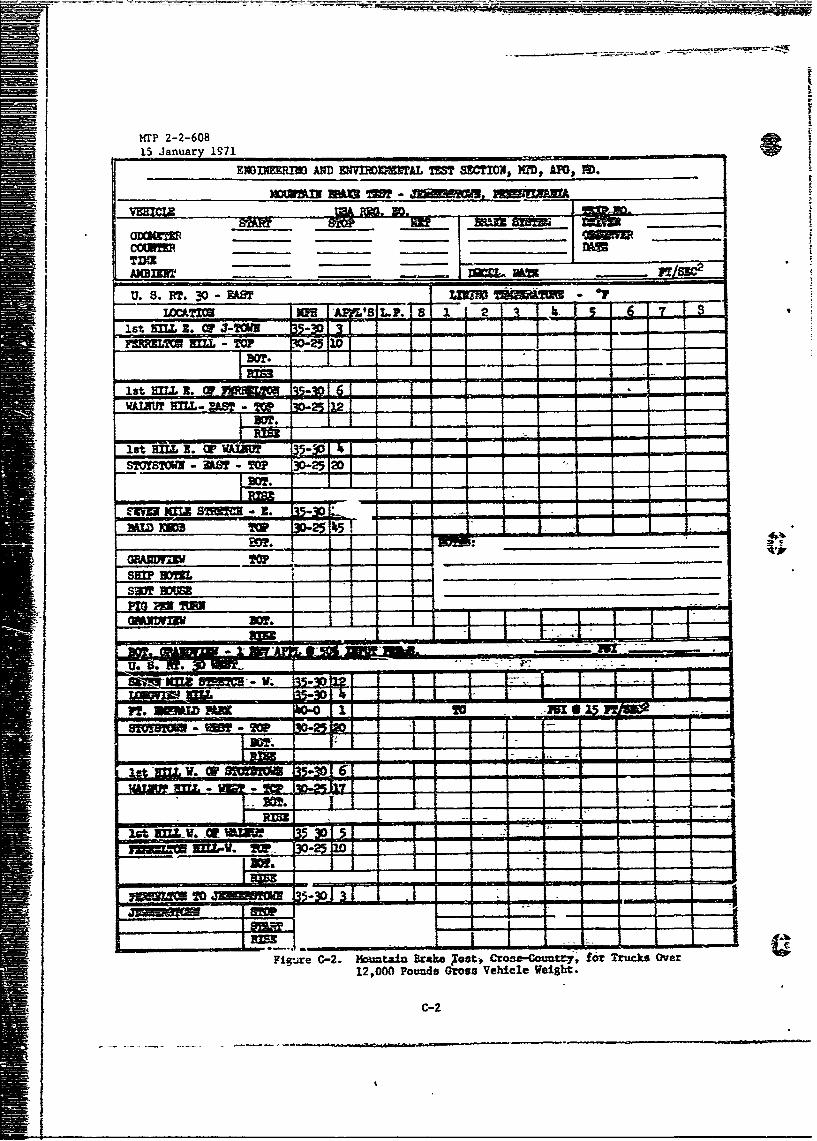
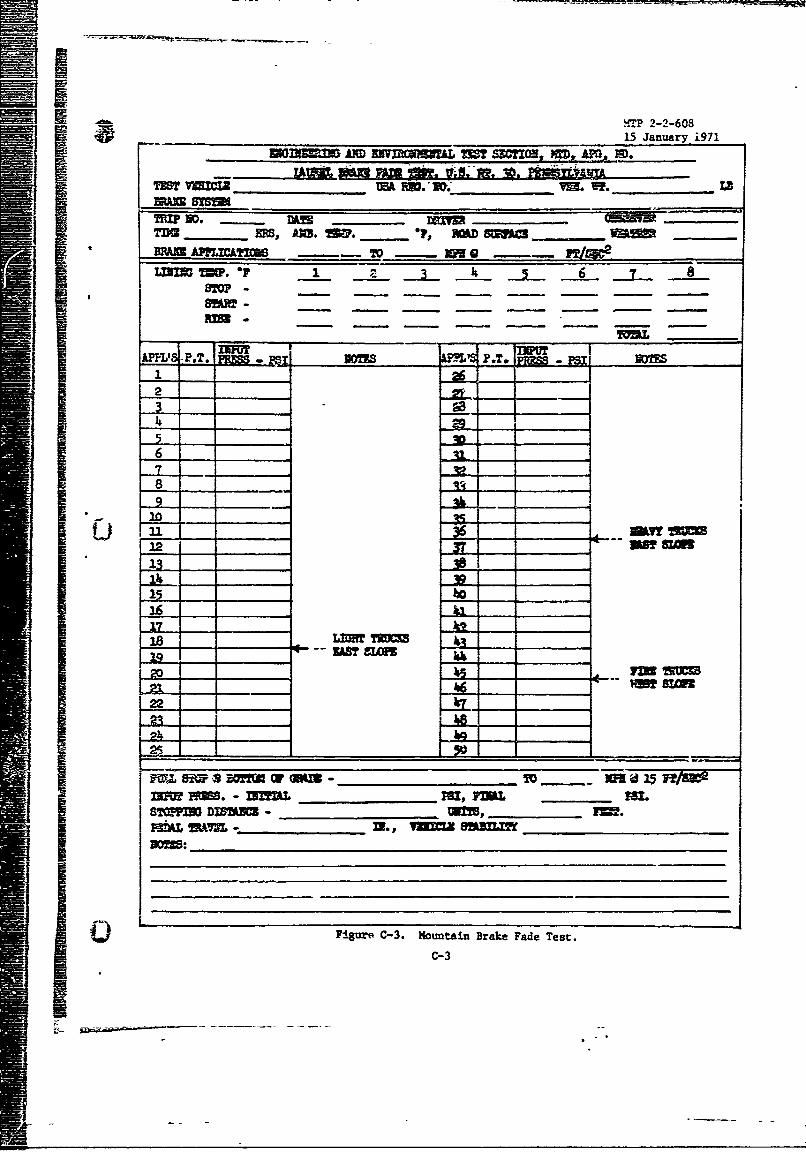
These tests are designed to be conducted over a 25-ile sectionof U. S. Route 30 in the Jennerstown area of western Pennsylvania. Test datato be recorded are indicated in Appendixes A, B and C.
6.2.3.1 Brake Fade Test
Brake fade characteristics will be dleter~ined during repeatedbraking operation over a downhill roadway of -a-roxisatel' 9 to 11 percentgrade ove. a distance of approximately 2 mile-s and a 40-mph full stop at thebottom of the grade.
Fade test procedures w'ill vary for vehicles of gross vehicle
weight classif ications as shown in Aoyeiidix k,- #eii 15.
The criteria for brake fade are.
a. Imedstely baI t1i!" dOw.z'ide b* gke snubbinig procedure,the test vehilid must d strattIee daIijltyqo 'uki a full stop atthe bottom of the grade as indicated in the Soll.oving table:
Gross Vehicle "Wdereraton Initial BrakingWeiU1it - Lb. PA te-- pt/ et-- Sje -M~
Up to 12,000 14.4 40
12,000 to 50,000 14.4 40
Over 50,000 lilp 30
b. Vehicle slew shall not exceed roadway lane width limitsequal to 1-1/2 times the overall width of the test vehicle.
6.2.3.2 High Temperature Endurance Test
A high tezperature highway brake test is conducted for the
-8-
:1!1
f15 Jan .ary 1971
purpose of evaluating the performance, fade, wear, and endurance character-istics of wheeled vehicle braking systems under conditions where elevatedbrake system temperatures and braking torques are a factor. The specifictest procedure is outlined in Appendix A. t.
NOTE: Since the temperatures reached by the brake linings maybe as high as 6000 to 800° F, climatic testing in thehot-dry conditions specitied in AR 70-38 is not necessarybecause the temperarres produced would be only insignifi-cantly higher than those obtained at standard temperatures.
The criteria are:
a. After the complete mountain highway brake test, brake com-ponent deterioration shall not have reduced vehicle stopping ability to apoint below the ninim requirements stated in paragraph 6.2.2.3.
b. Dzag e to brake, wheel, and suspension system components,such as bending, twisting, or breakage, shall not occur as a result of testoperation.
6.2.4 Brake Endurance Test
wle The mileages mcczlated during tests outlined in -MTP 2-2-5016will be used for brake enhurance evaluation as applicable for off-highwmyand general operation. Various components of wheeled vehicle braking systemsare subject to failure during these tests due to contamination by foreignabrasives and lubricants. Test operators will report incipient failuresduring the conduct of these tests for the determination of causes of specificmalfunctions. During the tests all failed parts will be labeled and re-tained along with samples of brake fluids and contaminating elements.
The criteria for off-highway braking system endurance are:
a. Brake component wear attributable to abrasives accumulatedduring normal vehicle endurance testing shall not reduce vehicle stoppingability to a point below the minim= requirements stated in paragraph 6.2.2.3over an accumulated span of 500 miles when test course surfaces are in a wet,muddy condition.
b. Damage to brake, wheel, and suspension system components,such as bending, twisting, or breakage, shall not occur as a result %f testoperation.
6.3 TEST DATA
All pertinent data will be recorded during the conduct of allbraking system tests. Data record sheets shown in Appendix C will be usedduring collection of test data.
-9-
ri1r Z-Z-o6
15 January 1971
6.4 DATA REDUCTION AND PRESENTATION
Data reduction and presentation requirements depend upon the ex-tent of the test conducted. The following presentations are represertative:
a. Graphs:
Pedal effort vs input pressureBrake effectiveness vs input pressure.Brake fade vs number of applications.Brake recovery vs number of applications.
b. Tabulations:
Brake temperature data.Brake component wear.
-10-
MR?4
HTP 2-2-60815 January 1971
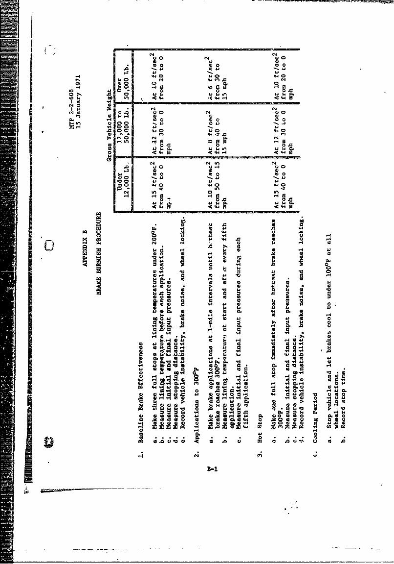
APPENDIX A
HOWlTAIN HIGHWAY BRAKE TEST OUTLINE
1. DisassEmble brake system completely.
2. Provide all new brake components.
3. Make pertinent initial brake component measure-ments.
4. Install calibrAted brake test instrumentation (pars, 3.2 and 6.1.1).
5. Reassemble brake system.
6. Adjust lining material to drum clearances to manufacturer'sspecifications.
7. Bleed hydraulically actuated brake systems per manufacturer a recommendedprocedure.
8. Run preburnisheffectiveness teets from 20 mph.
9. Burnish brakes to achieve at least 80 percent contact between thesurface areas of the lining and the drum (use either SAE J786 or APGprocedure sumarized in, App. B).
10. Readjust brakes tc recommended clearances.
11. Measure pedal ;force requirements over brake input pressure range.
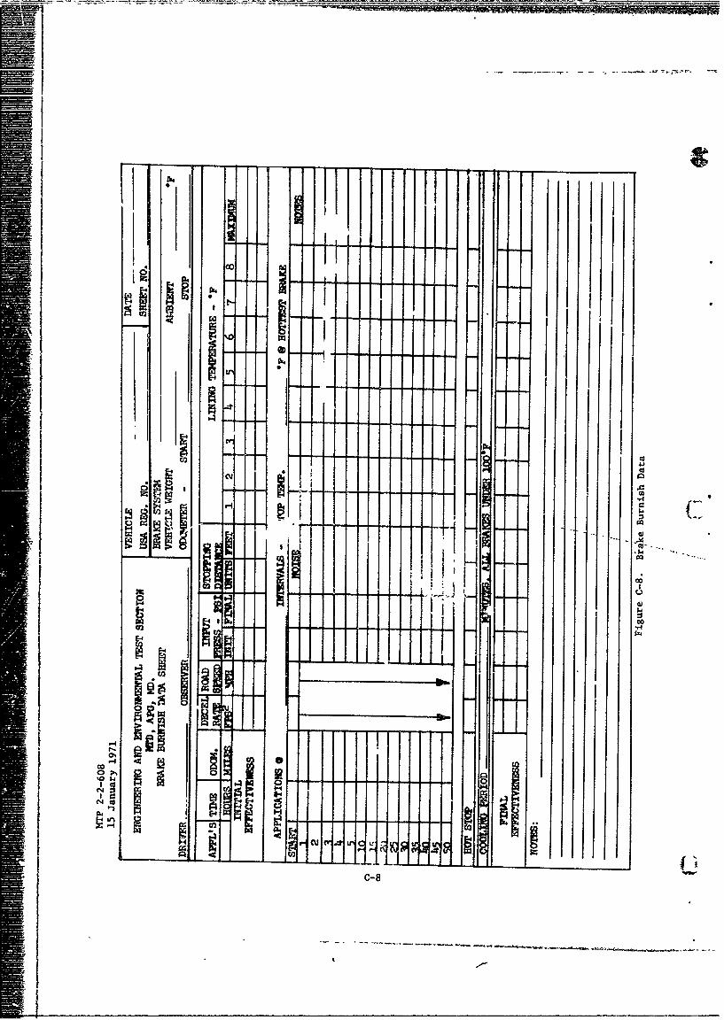
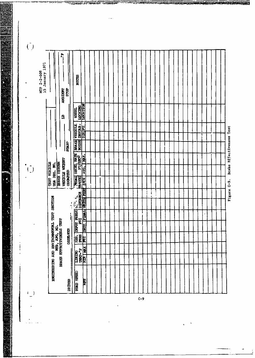
12. Run initial efretttiveness tests from 20 and 40 mph (Ref. Par. 6.2.2.3),recording data oo form of. Figure C-9.
13. Run initial fade test. (east side of Laurel Mountain, Fig. A-1),operating the vehicle Jowngradd-and accelerating between brake appli-cations as necessary to achieve required number of applications.
a. Snubbing and stopping rates per vehicle gro3s weight are as follows:
A-1
0
44.
0
CD cc
.. .......
V-4
#54J
000
C-4 cu
-46-2
.NHTP 2-2-60815 January 1971
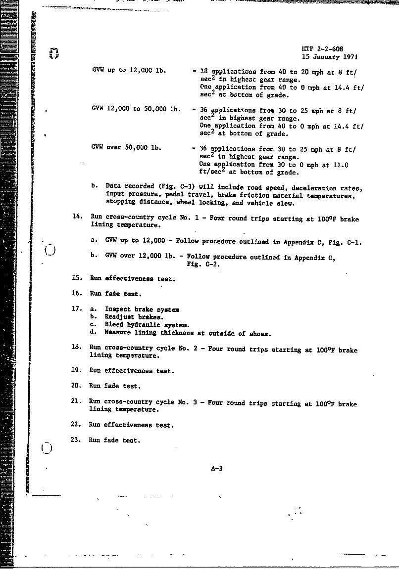
GVW up to 12,000 lb. 18 applications from 40 to 20 mph at 8 ft/sec 2 in highest gear range.One application from 40 to 0 mph at 14.4 ft/sec2 at bottom of grade.
GVW 12,000 to 50,000 lb. 36 applications from 30 to 25 mph at 8 ft/sec2 in highest gear range.One application from 40 to 0 mph at 14.4 ft/sec 2 at bottom of grade.
GVW over 50,000 lb. 36 applications from 30 to 25 mph at 8 ft/sec2 in highest gear range.One aplication from 30 to 0 mph at 11.0ft/cec' at bottom of grade.
b. Data recorded (Fig. C-3) will include road speed, deceleration rates,input pressure, pedal travel, brake friction material temperatures,stopping distance, wheel locking, and vehicle slew.
14. Run cross-country cycle No. 1 - Four round trips starting at 100OF brakelining temperature.
a. GVW up to 12,000 - Follow procedure outli-ned in Appendix C, Fig. C-1.
b. GVW over 12,000 lb. - Follow procedure outlined in Appendix C,Fig. C-2.
15. Run effectiveness test.
16. Run fade test.
17. a. Inspect brake systemb. Readjust brakes.c. Bleed hydraulic system.d. Measure lining thickness at outside of shoes.
18. Run cross-country cycle No. 2 - Four round trips starting at 100°F brakelining temprature.
19. Run effectiveness test.
20. Run fade test.
21, Run cross-country cycle No. 3 - Four round trips starting at 100°F brakelining temperature.
22. Run effectiveness test.
23. Run fade test.
A-3
rM 2.-2-60815 January 1971
24. Hake pertinent final brake component measitrements.
25. Remove instrumentation.
26. Reassemble brate system.
A:-4
0) U Qw0 0 4) 050
4.1 440$ 40 4.50 440 1
CD Q000 0
co0 0 OA10 r..0 0 415 wi W Ln f 4.5 ki0'0~t Li0 A , ~ 444 u-S 4.
NC1 o0 u 4 u0
A414m0 0) 0LM 00 00 toZ01
00 4.5U40 4.0.
00 4M 440 '.TC1 0 4 CJ4N4 tna 0 t 0
v. .0 0 0.04j p o.-Lip . 4 0.
0 44%w S44 40 444
mD -
a)~~ 0 041- 1 -4lo 41 4.5 410
840 .440 44
C- '-M 0 i-a 00
OD 0
go05 .4) 4.5 00 0 %64 =4 0 04
LiI Li 4 1o4.500 k 0) 0) 0 41
W 4. 0 4)54 0 .5 45 0 0o
U4 ~ 41 a. 4 0 . U
00 "4 0: so v 0'404 4.5 0'0 *
c 14.44 0 10. 4 44u A400- 0 4 0 z ~ 0-Sli
* v 9305 0 w4 to .5 00 ) 0 4U~0 0 1 i 9). 4) 'V .0
41 0 0.0d44 &Sfa0 co a.u4 40$4 '.5 41o ccU 0 . ~ .
4.5 to0 01 41. to 0 00U 40 4 $0. 54 0 ;p, :3 $4 '04 4; I4 0. .0 0.5 0'5Q4 0 0 0v
44 ~ ~ 1- co C-0v. W5 93p50. 50S0
t 41 r4 4 1 co 00!$ 4 '-A 4 0. a ~ .0 0 0 40-4 44 a45. a0 Q
.000 01 va-4 0 04 1-64-44Li' 444. 0.0040 U.
9~~~ a' es v 4 aiAii '5 CIO0 0. 9310 40 r4L
01 0 6 0 to. U 0050eco0 0.o0 * 0 0 04.44 0 4A0000 00 U
40 '-4 v. n --4 4939
V4 % o 0 a5 0r 10 .4. 0 -A .4 0 . .U
0.0 O S I 0, U0 "14 44 4 .0 10' r) d .0
4A ________V______P._______vE
14
. F 4 A
4l)
1410 OG
41 (1
0 Q) r .
00
J. o it~
0 C9 LM 0
124 .- M~
vi .~ t4 04
cc 0 * 41
a4 -.-
41 -S u. 34 4
>O 4h- 4 Q--
10 9 %
4+40-,0 to $4.j
is 41 .SB-iK9 0 9.04-4) a 6J *4 VS l 0:
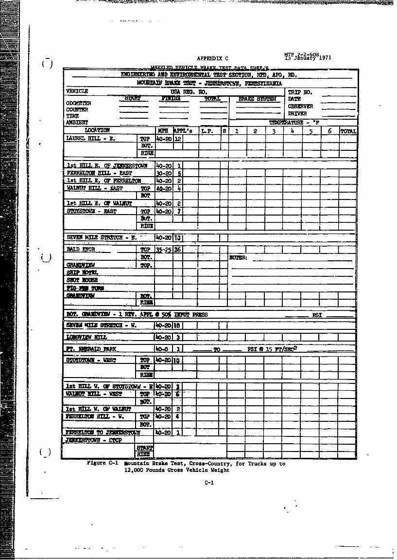
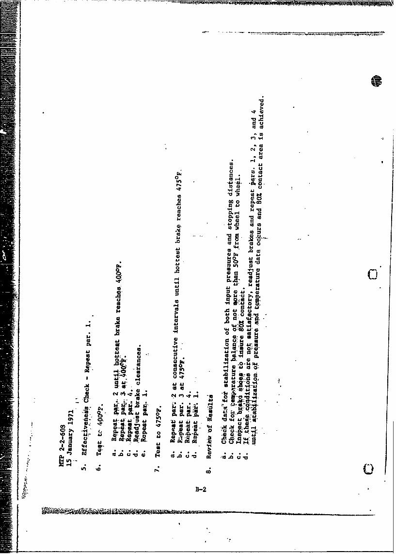
APPENDIX C ua y 1
1st IL B.I M. 80.ETO MOI2 20.
AMBTS - vBT 1.0 10]7
P810M 15 5 /SI
IMtMILW E I-~O -MT -302 -
_ _ _ __Z.OF1-2
1WA =-& T o2
i'gure - outIn BrkMet r03Cuty orTuk ptI12,00 PoILd Iro. Vehcl Weight,0-D
STOYSOW2 ZRS 20P40-2
--------
MTP 2-2-60815 January 1971
U.wo 5.a RT. 30 - EA
F!R~j mL I
? 2
-MX MA M, ID. - -vM t
ON -m -c -
ODSMM -~ IS O 02
-OVM DMT
-OAT -S L -8 1 - - 4. - 6 7is% E= 9. P w 3----
FEMM- a
m %W -3 -
wam~~ Em-mT
12,OSTOM Pod MUMs Veil WW3ig25t.
I R
2r --- 2-60815 January 1971
Tm Vm MlAm FM. W.' Vo V.
=MS, A3 1. - , MD =W=
BMAPMJICTI= To _ I
MW~ . ej 1 3 ~ j j jSTOP -sow -
TOML_
APNPL, -P.. p -. i .,. PSI-NOTES
=,2 ___ ___'_ __81 - _B
6
9 1-3-
13 '3
is -- - _ _ 43
-C-29 4
I-.- ___ __-
RMSi
_________IsBar=__ TO mma15
rim_____________2m6M, ?mUL ___
STOPI MUM - p_________ IM- tRL immW -____ ______ F., Y 1c SUSfLM ________________
- ~ Fig C-. Mountain Brake Fade Test.
-C-3
IMTP 2-2-60815 January 1971
~JmAMDvMM~ 8PCUMi MlDMD
N~Af 8~ flA1~2 AUMF - 1I.DTE: 8STAWT _ _ _ _ _ _ _ ~ _ _ _ _
LO-T -0 -
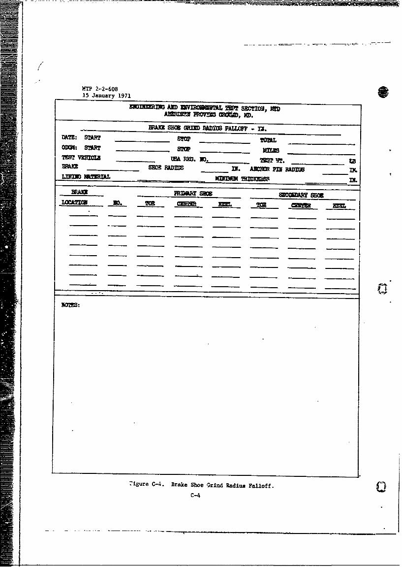
:igure C-4I. Brake Shoe g;rind Radius palloff.
C-4.
-~ KIP 2-2-608
END[I N mW, ~T SSTION, MTD
DATE: START _ __ _ STCP TOM 7~ _ _ __ _
0DCK: START ___ _____ STOP MILES____ __________
I_____ VEILEUA EmJ. NO. TEST_ WT. LB___ I.
LIRNG I4AM L _ _ _ _ _ _ __ _ _ _
IMTH - IN., wIT - IN., ~IF~ 1. R"JET EMPM 33.
AIAI N n z y AVG. MX_ _ _
AVMV ___ _j _
immIn, VIM -Mr., mczc IN., METx'x MM - i.
-=IC _ SM- - A
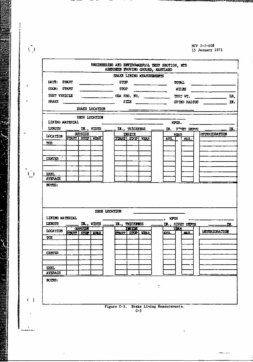
Figure C-5. Brake Ling Measurements.C-5
___ ~ -~- T1IE~ '. ~iu
HTP ?-2-6081.5 Janua-y 1971AY
EOflIMf~ J14D MURsr TST CION, it'D, APO, MD.
VEHICLE MW___ _ ___M_
DATE: START STOP TE_______ ST _______
011(9: START imp ______ TOTAL __
STR STP WA Rl O WUH TkR SUOP WEAR s~oF mR
CENTER
FACE PLAT
OPENIN
FACE PIAT
AVERAGE
IAfTJIO -5_ 6 78ISTARTSTO WEAR ___I STOP IWEAR SATSTOP WWA START STOP WEaR
FACE PUTE.-
PACE KTATE -
____ STOP L131*0
-2
-4
678 j
NOTES:
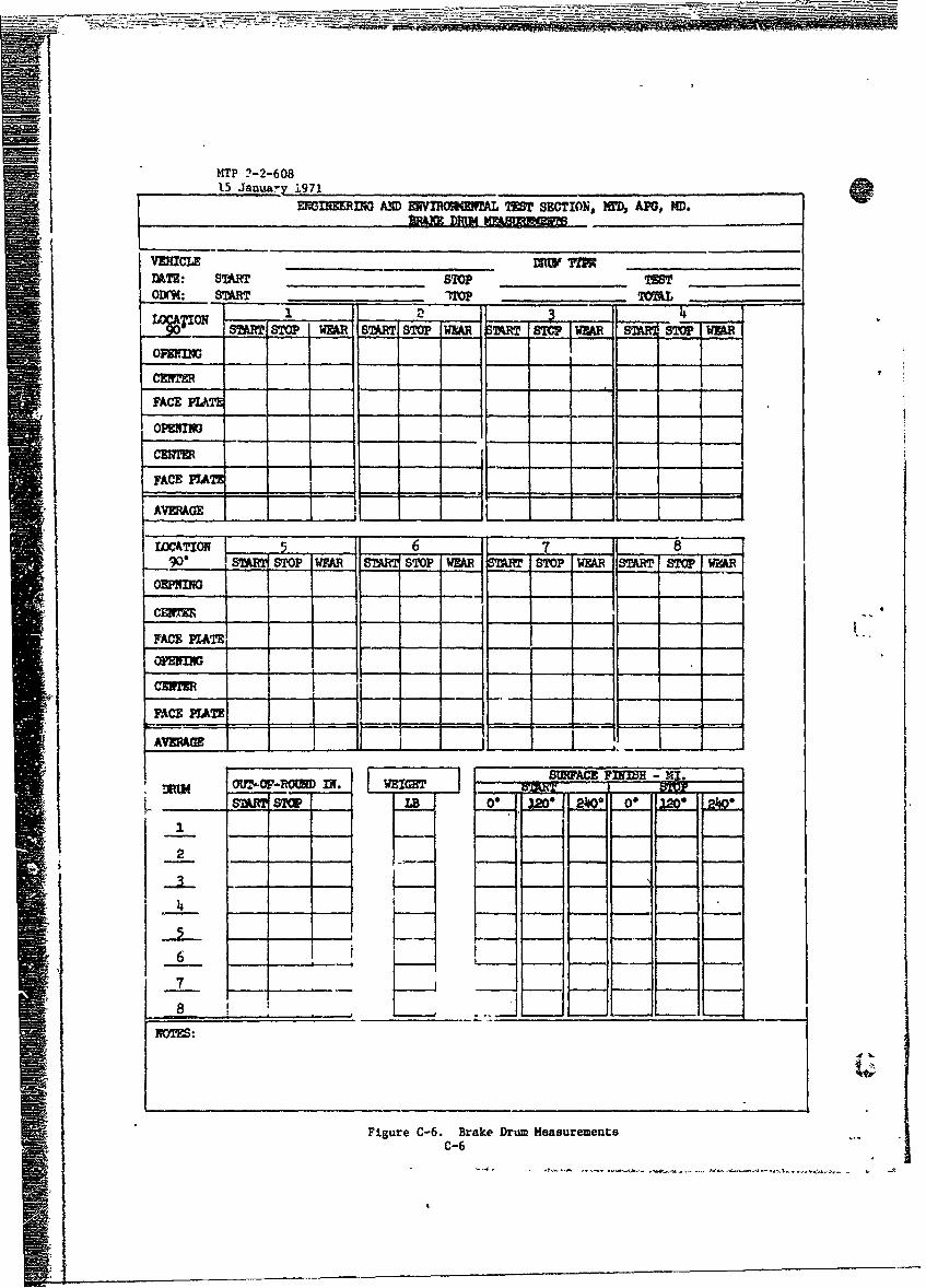
Figure C-6. Brake Drum MeasurementsC-6
15 January 1971
,ARD i L0 GROW , ,WR , OAI
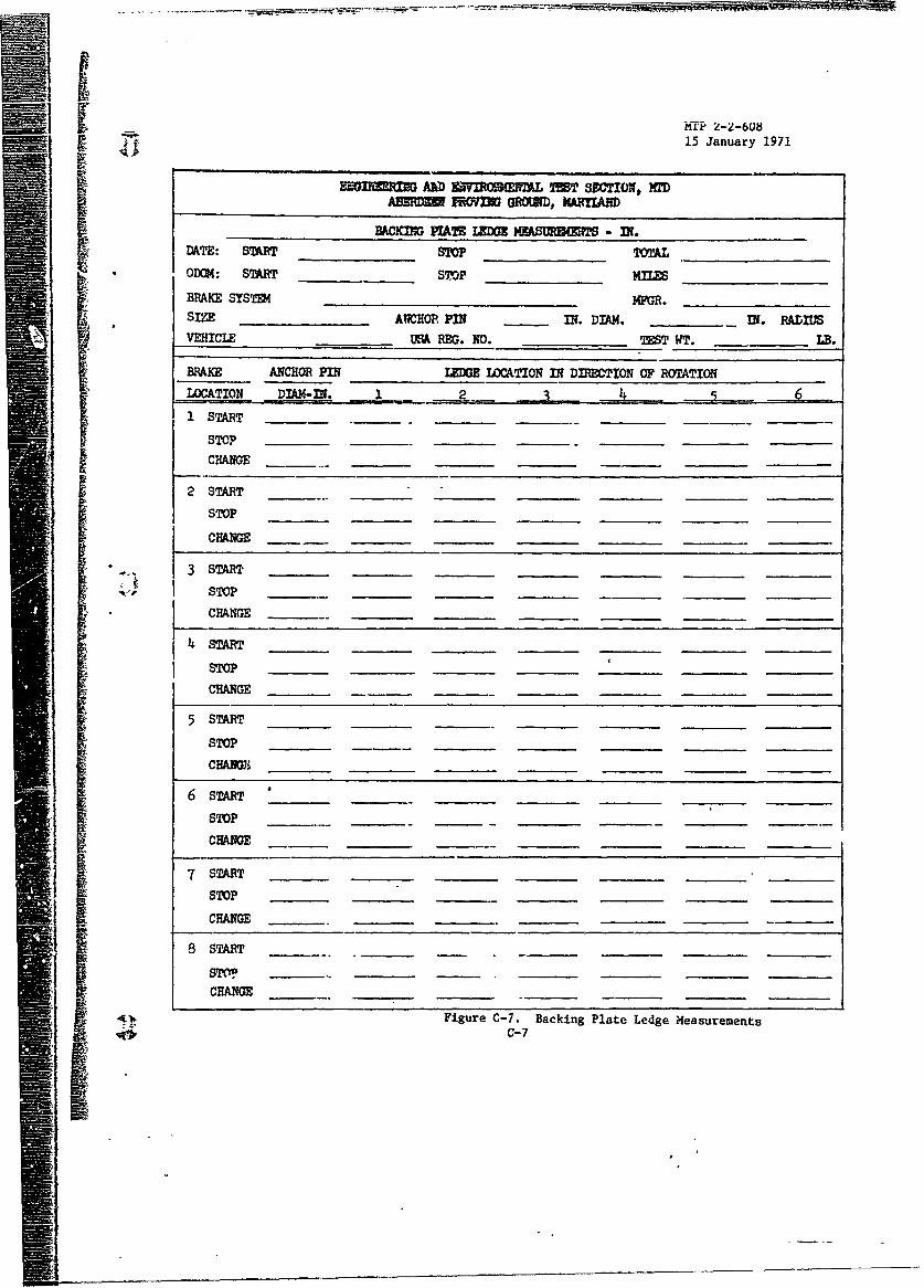
MACKID PA IJLDG MWXY M - IN.DATE: START STOP TOTALOD4: START STOP MIESBRAKE SYSTM4 M__.SIZE ANCHOR PIN IN. DIAM. IN. RADIUSVEHICLE USA REG. NO. TEST WT. LB.
BRAKE ANCHOR PIN LEDGE LOCATION IN DIRECTION OF ROTATIONLOCATION DIAM-IN. 12 ,3 J -1 START
STOPCHANGE
2 START
STOP
CHANGE
3START ____ ____ ____ ____ ____ ____ ____
,4 I, STOPCHANGE
47 START
STOP
CHANGE
5 START
STOP
CHANG _
6 START
STOP
j ~~~~CHANGE ____ _____ ___
7 START
STOP
CHANEG
8 START
STCM _ _ _
CHANGE
Figure C-7. Backing Plate Ledge MeasurementsC-7
09
0
C4
I
* I C-8
- == - -. ._
-I1
,-$4
in
I I I I I I IJ I i
C-9i--
I ----1
UN4CLASSU1eED Z O
DOCUMENT CON4TROL IDATA It&D(sociffity classaification olf fil* be* of abetract and4 hyEj***jftuigate anhl be GoR white M*1 *vws -gwt to ef**8ift4)
1. ORIGINATING ACTIVITY (C.Epecto sgHN~ae) &&. REPORT SECURITY CLAgSFICATON
U.S. Army Test & Evaluation Conand UNCLASSI71EDAberdeen Proving Ground, Maryland 21005 5b.* GROUP
REIM U.S. Army Test and Evaluation Command Materiel Test ProcedureCommon Engineering Test Procedure "Braking, Wheeled Vehicles"
4. OZSCRIPTIVEK NOTES (T7p4 of lepal and Ancoloi. date)
Final- j S~~~. AU THORIS) (Pdn iro! d. nta&fc ae
W. RIMPORT DATE 74. TOTAL 00. OF PAES0*.N. OF REPS8
15 January 1971 27 1 869L CONTRACT OR GRANT NO. Sa& ORIGINATORS REPORT NW*StKRCS)
6PROJECT NO. MT 2-2-608AMCR 310-6
0. THERREORT NO00) (Aw' fat M1n~ 012 8107 So 401810
10. OISTRIOUTION STATEMENT
A Distribution of this document is unlimited
II-1 SUPPLEMENTARY NOTES 1I:. SPOHOORMIS UILITARY ACTIVITY
I HeadquartereI U.S. Army Test and Evaluation Coand
4 ~SR~ Aberdeen Priyviig Ground., Maryand 21005
Procedures are described f or .valuating the braking ability of wheeled vehicles fromiat gross weights up to, and in excess of 50,000 lbs. Water imrsion, high and lowtemperature operation, and breaking effectiveness are described.e)
DDF Irmoe473 02L~aEs u~ n~A D-1 -~ QASjE
Ui1CLASsIFlED
- LSUK A LINK 0 L I Pk. Z_ _ _ _ _ _ _ _ _ _ _ S o W * "a~ _ _ n O L E Z V
Braking ability jBrake burnishBrake i=ersionBrake Fade
a
II
ItDm.......... -------
D-2
Socwft Closactm