MTL4500/5500 range - MTL Instruments · • Multi-channel I/O ... vendors in mind for...
55
March 2018 EPS 45/5500 Rev 14 Technical data MTL intrinsic safety solutions 1 Eaton Electric Limited, Great Marlings, Butterfield, Luton Beds, LU2 8DL, UK. Tel: + 44 (0)1582 723633 Fax: + 44 (0)1582 422283 E-mail: [email protected] www.mtl-inst.com © 2018 Eaton All Rights Reserved Publication No. EPS 45/5500 Rev 14 March 2018 EUROPE (EMEA): +44 (0)1582 723633 [email protected] THE AMERICAS: +1 800 835 7075 [email protected] ASIA-PACIFIC: +65 6 645 9888 [email protected] The given data is only intended as a product description and should not be regarded as a legal warranty of properties or guarantee. In the interest of further technical developments, we reserve the right to make design changes. • 3-port isolation as standard • Highest module/channel packing densities • Low power dissipation • Quick install and release mechanism • Multi-channel I/O modules • Broken line monitoring • Compatible with preceding MTL isolator range for pluggable replacements • Various models assessed for use in Functional Safety applicatons MTL4500/5500 range Intrinsically safe galvanic isolators Eaton's latest generation of MTL IS interfaces utilises an innovative "One-Core" technology to ensure the highest quality and availability while maintaining maximum flexibility at lowest cost. Incorporating advanced circuit design, a common set of components and innovative isolating transformer construction, they achieve a significant reduction in power consumption while increasing channel packing densities. The compact, 16mm wide design reduces weight and gives exceptionally high packing density. They build on the proven success of the MTL2000, 3000, 4000 and 5000 range to bring the benefits of new developments in galvanic isolation without compromising the reliability of the designs from which they have evolved. The backplane mounting MTL4500 range is designed with system vendors in mind for "project-focussed" applications such as Distributed Control System (DCS), Emergency Shutdown Systems (ESD) and Fire and Gas monitoring (F&G). The reduced power consumption and high efficiency enable high signal density to be achieved together with improved freedom in cabinet layout and design. Easy integration with the input/output assemblies of control or safety instrumentation systems not only simplifies project engineering but also reduces installation and maintenance costs. A multiway connector to the backplane provides safe-area and power supply connections, while hazardous-area connections plug into the front of the module, simplifing installation and maintenance and reducing time, cost, and the risk of errors. The DIN-rail mounting MTL5500 range meets the needs of the IS interface market for "application focussed" projects, ranging from single instrument loops, through to fully equipped cabinets, across all industries where hazardous areas exist. The MTL5500 clips quickly onto DIN rail, so it is compatible with the industry-standard mounting system. Wiring is simplified by plug-in safe- and hazardous-area connectors, and a power plug which accepts a power bus; it all leads to quicker insertion, fewer wiring errors and trouble-free, tidier installations. Line fault detection (LFD) facilities are provided across the range of I/O functions; on the switch/proximity detectors, the MTL4523/5523 solenoid/alarm drivers and the isolating drivers. Analogue input units such as the MTL4541/5541 provide line fault detection by repeating o/c or s/c currents to the safe-area control system. Status LEDs, configuration switches and ports are located on the top or side of individual modules, as appropriate, for easy access. Both ranges have been designed for compatiblity with earlier models. The MTL4500 range provides plug-replacements for the earlier MTL4000 units, while the MTL5500 range can easily replace MTL5000 units. Each offer the latest in modern technology and efficiency without compromise. In addition to their use in IS circuits, specific models within the MTL4500 and MTL5500 range have been assessed and approved for use in Functional Safety applications. These have been verified under the certified Functional Safety Management (FSM) programme implemented by our MTL product line.
Transcript of MTL4500/5500 range - MTL Instruments · • Multi-channel I/O ... vendors in mind for...
March 2018EPS 45/5500 Rev 14
Technical data MTL intrinsic safety solutions
1
Eaton Electric Limited, Great Marlings, Butterfield, LutonBeds, LU2 8DL, UK.Tel: + 44 (0)1582 723633 Fax: + 44 (0)1582 422283E-mail: [email protected]
© 2018 EatonAll Rights ReservedPublication No. EPS 45/5500 Rev 14March 2018
EUROPE (EMEA):
+44 (0)1582 723633 [email protected]
THE AMERICAS:
+1 800 835 7075 [email protected]
ASIA-PACIFIC:
+65 6 645 9888 [email protected]
The given data is only intended as a product description and should not be regarded as a legal warranty of properties or guarantee. In the interest of further technical developments, we reserve the right to make design changes.
• 3-port isolation as standard
• Highest module/channel packing densities
• Low power dissipation
• Quick install and release mechanism
• Multi-channel I/O modules
• Broken line monitoring
• Compatible with preceding MTL isolator range for pluggable replacements
• Various models assessed for use in Functional Safety applicatons
MTL4500/5500 range Intrinsically safe galvanic isolators
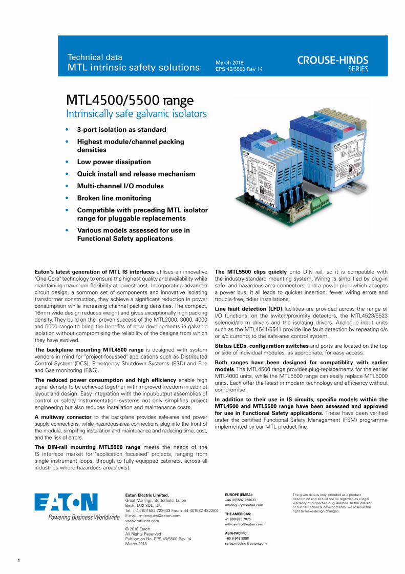
Eaton's latest generation of MTL IS interfaces utilises an innovative "One-Core" technology to ensure the highest quality and availability while maintaining maximum flexibility at lowest cost. Incorporating advanced circuit design, a common set of components and innovative isolating transformer construction, they achieve a significant reduction in power consumption while increasing channel packing densities. The compact, 16mm wide design reduces weight and gives exceptionally high packing density. They build on the proven success of the MTL2000, 3000, 4000 and 5000 range to bring the benefits of new developments in galvanic isolation without compromising the reliability of the designs from which they have evolved.
The backplane mounting MTL4500 range is designed with system vendors in mind for "project-focussed" applications such as Distributed Control System (DCS), Emergency Shutdown Systems (ESD) and Fire and Gas monitoring (F&G).
The reduced power consumption and high efficiency enable high signal density to be achieved together with improved freedom in cabinet layout and design. Easy integration with the input/output assemblies of control or safety instrumentation systems not only simplifies project engineering but also reduces installation and maintenance costs.
A multiway connector to the backplane provides safe-area and power supply connections, while hazardous-area connections plug into the front of the module, simplifing installation and maintenance and reducing time, cost, and the risk of errors.
The DIN-rail mounting MTL5500 range meets the needs of the IS interface market for "application focussed" projects, ranging from single instrument loops, through to fully equipped cabinets, across all industries where hazardous areas exist.
The MTL5500 clips quickly onto DIN rail, so it is compatible with the industry-standard mounting system. Wiring is simplified by plug-in safe- and hazardous-area connectors, and a power plug which accepts a power bus; it all leads to quicker insertion, fewer wiring errors and trouble-free, tidier installations.
Line fault detection (LFD) facilities are provided across the range of I/O functions; on the switch/proximity detectors, the MTL4523/5523 solenoid/alarm drivers and the isolating drivers. Analogue input units such as the MTL4541/5541 provide line fault detection by repeating o/c or s/c currents to the safe-area control system.
Status LEDs, configuration switches and ports are located on the top or side of individual modules, as appropriate, for easy access.
Both ranges have been designed for compatiblity with earlier models. The MTL4500 range provides plug-replacements for the earlier MTL4000 units, while the MTL5500 range can easily replace MTL5000 units. Each offer the latest in modern technology and efficiency without compromise.
In addition to their use in IS circuits, specific models within the MTL4500 and MTL5500 range have been assessed and approved for use in Functional Safety applications. These have been verified under the certified Functional Safety Management (FSM) programme implemented by our MTL product line.

2
© 2018 EatonAll Rights ReservedPublication No.
Eaton Electric Limited, Great Marlings, Butterfield, LutonBeds, LU2 8DL, UK.Tel: + 44 (0)1582 723633 Fax: + 44 (0)1582 422283E-mail: [email protected]
EUROPE (EMEA):
+44 (0)1582 723633 [email protected]
THE AMERICAS:
+1 800 835 7075 [email protected]
ASIA-PACIFIC:
+65 6 645 9888 [email protected]
ISOLATOR FUNCTION SELECTORMTL4500 (Backplane) MTL5500 (DIN-rail) FSM Channels Function
Digital InputMTL4501-SR
MTL5501-SR √ 1 fail-safe solid-state output + LFD alarm MTL4504 – √ 1 switch/prox input, phase reversal + LFDMTL4510 MTL5510 4 switch/prox input, solid-state outputMTL4510B MTL5510B 4 multi-function switch/prox input, solid-state outputMTL4511 MTL5511 √ 1 switch/prox input, c/o relay outputMTL4513 MTL5513 2 switch/prox input, solid-state outputMTL4514/B MTL5514 √ 1 switch/prox input, relay + LFDMTL4514D MTL5514D √ 1 switch/prox input, dual output relayMTL4514N – √ 1 switch/prox input, relay + LFDMTL4516 – √ 2 switch/prox input, relay + LFD outputs MTL4516C MTL5516C √ 2 switch/prox input, c/o relay + LFD outputsMTL4517 MTL5517 √ 2 switch/prox input, relay + LFD outputs
Digital OutputMTL4521
MTL5521 √ 1 loop powered solenoid driverMTL4521L – √ 1 loop powered solenoid driver, IIC – MTL5522 √ 1 loop powered solenoid driver, IIBMTL4523 MTL5523 √ 1 solenoid driver with LFDMTL4523L – √ 1 loop powered solenoid driver with LFDMTL4523R – √ 1 solenoid driver with reverse LFDMTL4523V MTL5523V √ 1 solenoid driver with LFD, IICMTL4524 MTL5524 √ 1 switch operated solenoid driverMTL4524S – √ 1 switch operated solenoid driver, 24V overrideMTL4525 MTL5525 √ 1 switch operated solenoid driver, low powerMTL4526 MTL5526 2 switch operated relay
Pulse & VibrationMTL4531
MTL5531 √ 1 vibration probe interface
MTL4532 MTL5532 1 pulse isolator, digital or analogue output
Analogue InputMTL4541
MTL5541 √ 1 2/3 wire transmitter repeaterMTL4541A MTL5541A √ 1 transmitter repeater, passive inputMTL4541AS MTL5541AS √ 1 transmitter repeater, passive input, current sinkMTL4541S MTL5541S √ 1 2/3 wire transmitter repeater, current sinkMTL4541T – 1 2/3 wire transmitter repeater, long cablesMTL4544 MTL5544 √ 2 2/3 wire transmitter repeaterMTL4544A MTL5544A √ 2 transmitter repeater, passive inputMTL4544AS MTL5544AS √ 2 transmitter repeater, passive input, current sinkMTL4544S MTL5544S √ 2 2/3 wire transmitter repeater, current sinkMTL4544D MTL5544D √ 1 2/3 wire transmitter repeater, dual output
Analogue OutputMTL4546
MTL5546 √ 1 4-20mA smart isolating driver + LFDMTL4546S – 1 4-20mA smart isolating driver + LFDMTL4546Y MTL5546Y √ 1 4-20mA smart isolating driver + oc LFDMTL4549 MTL5549 √ 2 4-20mA smart isolating driver + LFDMTL4549Y MTL5549Y √ 2 4-20mA smart isolating driver + oc LFD
Fire & SmokeMTL4561
MTL5561 √ 2 loop-powered, for fire and smoke detectors
Temperature InputMTL4573
MTL5573 1 temperature converter, THC or RTDMTL4575 MTL5575 1 temperature converter, THC or RTDMTL4576-RTD MTL5576-RTD 2 temperature converter, RTDMTL4576-THC MTL5576-THC 2 temperature converter, THCMTL4581 MTL5581 1 mV/mV isolatorMTL4582B MTL5582B √ 1 RTD/RTD isolator
GeneralMTL4599 MTL5599 – dummy moduleMTL4599N – – general purpose feed-through module
EPS45/5500 Rev13 150517

3
© 2018 EatonAll Rights ReservedPublication No.
Eaton Electric Limited, Great Marlings, Butterfield, LutonBeds, LU2 8DL, UK.Tel: + 44 (0)1582 723633 Fax: + 44 (0)1582 422283E-mail: [email protected]
EUROPE (EMEA):
+44 (0)1582 723633 [email protected]
THE AMERICAS:
+1 800 835 7075 [email protected]
ASIA-PACIFIC:
+65 6 645 9888 [email protected]
The given data is only intended as a product description and should not be regarded as a legal warranty of properties or guarantee. In the interest of further technical developments, we reserve the right to make design changes.
MTL4501-SR – MTL5501-SR FAIL-SAFE SWITCH/PROXIMITY- DETECTOR INTERFACEwith LFD
With the MTLx501-SR, a fail-safe switch/proximity detector located in the hazardous area can control an isolated fail-safe electronic output. The MTLx501-SR also provides relay alarm contacts to signal line-fault conditions. The MTLx501-SR is for use with approved fail-safe sensors in loops that require operation up to SIL3 according to the functional safety standard IEC 61508.
SPECIFICATIONSee also common specification
Number of channelsOne
Location of switchesZone 0, IIC, T6 hazardous areaDiv. 1, Group A hazardous location
Location of proximity detectorZone 0, IIC, T4–6, hazardous locationDiv 1, Group A, hazardous location
Voltage applied to sensor8.6V dc max from 1kΩ
Input/output characteristics
Input value in sensor circuits
Fail–safe output
Operation LFD contacts
2.9mA < Is < 3.9mA ON Normal CLOSED
Is < 1.9mA & Is > 5.1mA OFF Normal CLOSED
Is < 50µA OFF Broken line OPEN
Rs < 100Ω OFF Shorted line OPEN
Note: Is = sensor current
Fail-safe electronic outputOutput on: 24V nominalOutput off: 0V dc, max < 5V dcLoad: 750Ω to 10kΩMaximum on-state current: 25mA (at 750Ω)Short-circuit current: 30mA
Line fault detection (LFD)LFD relay output: contacts open when line fault detectedSwitch characteristics: 0.3A 110V ac/dc; 1A 35V dc; 30W/33VA
LED indicatorsGreen: power indicationYellow: channel status, on when fail-safe output energisedRed: LFD indication, flashing when line fault detected
Hazardous area Safe area
Vs–Vs+
20 to 35V dc
10kΩ
1k4Ω
+
–
LFD
Failsafe output+
–Resistors mustalways be fitted for switch inputs
654
321
789
101112
1314
Power requirements, Vs@ Supply voltage 750Ω load typ. load
20V dc 100mA 70mA24V dc 90mA 60mA35V dc 65mA 45mA
Power dissipation within unit@ Supply voltage 750Ω load typ. load
20V dc 1232mW 1160mW24V dc 1392mW 1200mW35V dc 1507mW 1335mW
Safety descriptionUo = ±9.7V, Io = 30mA, Po = 0.07W, Ci = 0nF, Li = 0mHUm = 253V
SIL3
IEC 61508:2010
SIL capableHighest level in single in-line subsystem - SIL3 (in accordance with IEC61508-2)See data on MTL web site and refer to the safety manual.
MTL5501-SR
MTL4501-SR
Hazardous area Safe area
FSM FUNCTIONAL SAFETY
MANAGEMENT
IEC 61508:2010
EPSx501SR Rev5 010916

4
© 2018 EatonAll Rights ReservedPublication No.
Eaton Electric Limited, Great Marlings, Butterfield, LutonBeds, LU2 8DL, UK.Tel: + 44 (0)1582 723633 Fax: + 44 (0)1582 422283E-mail: [email protected]
EUROPE (EMEA):
+44 (0)1582 723633 [email protected]
THE AMERICAS:
+1 800 835 7075 [email protected]
ASIA-PACIFIC:
+65 6 645 9888 [email protected]
The given data is only intended as a product description and should not be regarded as a legal warranty of properties or guarantee. In the interest of further technical developments, we reserve the right to make design changes.
MTL4504SWITCH/ PROXIMITYDETECTOR INTERFACE1-channel with LFD and phase reversal
The MTL4504 enables a safe–area load to be controlled, through a relay, by a proximity detector or switch located in a hazardous area. Line faults are signalled through a separate relay and indicated on the top of the module. MTBF information for the LFD relay is available from Eaton to allow the failure rate for the LFD relay to be calculated when used in the critical path with the output relay for safety critical applications. Switches are provided to select phase reversal and to enable the line fault detection.
SPECIFICATIONSee also common specification
Number of channelsOne
Location of switchZone 0, IIC, T6 hazardous areaDiv.1, Group A, hazardous location
Location of proximity detectorZone 0, IIC, T4–6 hazardous area, if suitably certifiedDiv.1, Group A, hazardous location
Hazardous–area inputsInputs conforming to BS EN60947–5–6:2001 standards for proximity detectors (NAMUR)
Voltage applied to sensor7 to 9V dc from 1kΩ ±10%
Input/output characteristicsNormal phase Outputs closed if input > 2.1mA (< 2kΩ in input circuit) Outputs open if input < 1.2mA (> 10kΩ in input circuit)Hysteresis: 200µA (650Ω) nominal
Line fault detection (LFD) (when selected)User-selectable via switches on the side of the unit. Line faults are indicated by an LED. Line fault relay is de-energised and channel output relay de-energised if input line-fault detectedOpen-circuit alarm on if Iin < 50µAOpen-circuit alarm off if Iin > 250µAShort-circuit alarm on if Rin < 100ΩShort-circuit alarm off if Rin > 360ΩNote: Resistors must be fitted when using the LFD facility with a contact input
500Ω to 1kΩ in series with switch 20kΩ to 25kΩ in parallel with switch
Safe-area output Channel: Single pole relay with changeover contactsLFD: Single pole relay with changeover contacts
Note: reactive loads must be adequately suppressed
Relay characteristics
MTL4504
Response time: 10ms maximum
Contact rating (Safe Area):
10W, 0.5A, 35V dc
Contact rating (Zone 2):
10W, 0.5A, 35V dc
LED indicatorsGreen: power indicationYellow: channel status, on when output energisedRed: LFD indication, on when line fault detected
Maximum current consumption 25mA at 24V dc
Power dissipation within unit0.6W at 24V
Safety descriptionUo=10.5V Io=14mA Po=37mW Um = 253V rms or dc
SIL capableThese models have been assessed for use in IEC 61508 functional safety applications. SIL2 capable for a single device (HFT=0) SIL3 capable for multiple devices in safety redundant configurations (HFT=1) See data on MTL web site and refer to the safety manual.
MTL4504
22kΩ
680Ω
+
–
Output
LFD
Switch-type sensorsrequire resistorsif LFD is selected
Vs–Vs+
20 to 35V dc
To earth-leakage detector *
654
321
LFD
987
121110
13 14
Hazardous area Safe area
FSM FUNCTIONAL SAFETY
MANAGEMENT
IEC 61508:2010
EPS4504 Rev6 240517
SIL2
IEC 61508:2010
SIL3
IEC 61508:2010

5
© 2018 EatonAll Rights ReservedPublication No.
Eaton Electric Limited, Great Marlings, Butterfield, LutonBeds, LU2 8DL, UK.Tel: + 44 (0)1582 723633 Fax: + 44 (0)1582 422283E-mail: [email protected]
EUROPE (EMEA):
+44 (0)1582 723633 [email protected]
THE AMERICAS:
+1 800 835 7075 [email protected]
ASIA-PACIFIC:
+65 6 645 9888 [email protected]
The given data is only intended as a product description and should not be regarded as a legal warranty of properties or guarantee. In the interest of further technical developments, we reserve the right to make design changes.
Hazardous area Safe area
Ch B
Vs–Vs+
20 to 35V dc
–+–
–+–
Ch D
Ch C
Ch A
1
2
3
4
common
common
Outputs
654
321
789
101112
1314
MTL5510
MTL4510
Hazardous area Safe area
Ch B –+–
–+–
Ch D
Ch C
Ch A
1
2
3
4
common
common
Outputs
Vs–Vs+
20 to 35V dc
654
321
987
121110
13 14
MTL4510 – MTL5510 SWITCH/ PROXIMITY DETECTOR INTERFACE4-channel, digital input
The MTLx510 enables four solid-state outputs in the safe area to be controlled by up to four switches or proximity detectors located in a hazardous area. Each pair of output transistors shares a common terminal and can switch +ve or –ve polarity signals. A range of module configurations is available (see Table 1) through the use of selector switches. When proximity detector modes are selected, LFD is enabled and the output switches to OFF if a line fault is detected.
SPECIFICATIONSee also common specification
Number of channels4, configured by switches
Location of switchesZone 0, IIC, T6 hazardous areaDiv 1, Group A hazardous location
Location of proximity detectorsZone 0, IIC, T4-6 hazardous area if suitably certifiedDiv 1, Group A, hazardous location
Hazardous-area inputsInputs conforming to BS EN60947–5–6:2001 standards for proximity detectors (NAMUR)
Voltage applied to sensor7 to 9V dc from 1kΩ ±10%
Input/output characteristicsNormal phase Outputs closed if input > 2.1mA (< 2kΩ in input circuit) Outputs open if input < 1.2mA (> 10kΩ in input circuit)Hysteresis: 200µA (650Ω) nominal
Line fault detection (LFD) (when selected)User-selectable via switches on the side of the unit. Open-circuit alarm on if Iin < 50µAOpen-circuit alarm off if Iin > 250µAShort-circuit alarm on if Rin < 100ΩShort-circuit alarm off if Rin > 360ΩNote: Resistors must be fitted when using the LFD facility with a contact input
500Ω to 1kΩ in series with switch 20kΩ to 25kΩ in parallel with switch
Safe-area outputs Floating solid-state outputs compatible with logic circuitsOperating frequency: dc to 500HzMax. off-state voltage: ± 35VMax. off-state leakage current: ± 50µAMax. on-state resistance: 25ΩMax. on-state current: ± 50mA
LED indicatorsGreen: power indicationYellow: four: on when output activeRed: LFD indication + faulty channel’s yellow LED flashes
Maximum current consumption 40mA at 24V (with all output channels energised)
Power dissipation within unit0.96W at 24V, with 10mA loads
Safety description (each channel)Uo=10.5V Io=14mA Po=37mW Um = 253V rms or dc
Table 1 - Mode options
MODE o/p 1 o/p 2 o/p 3 o/p 4 i/p type
0 chA chB chC chD
switch
1 chA rev. chB chC chD
2 chA chB rev. chC chD
3 chA chB chC rev. chD
4 chA chB chC chD rev.
5 chA rev. chB chC rev. chD
6 chA chB rev. chC chD rev.
7 chA rev. chB rev. chC rev. chD rev.
8 chA chB chC chD
prox. detector + LFD
9 chA rev. chB chC chD
10 chA chB rev. chC chD
11 chA chB chC rev. chD
12 chA chB chC chD rev.
13 chA rev. chB chC rev. chD
14 chA chB rev. chC chD rev.
15 chA rev. chB rev. chC rev. chD rev.
See Instruction Manual INM4500 or INM5500 for further mode information.
EPSx510 Rev4 010916
6
© 2018 EatonAll Rights ReservedPublication No.
Eaton Electric Limited, Great Marlings, Butterfield, LutonBeds, LU2 8DL, UK.Tel: + 44 (0)1582 723633 Fax: + 44 (0)1582 422283E-mail: [email protected]
EUROPE (EMEA):
+44 (0)1582 723633 [email protected]
THE AMERICAS:
+1 800 835 7075 [email protected]
ASIA-PACIFIC:
+65 6 645 9888 [email protected]
The given data is only intended as a product description and should not be regarded as a legal warranty of properties or guarantee. In the interest of further technical developments, we reserve the right to make design changes.
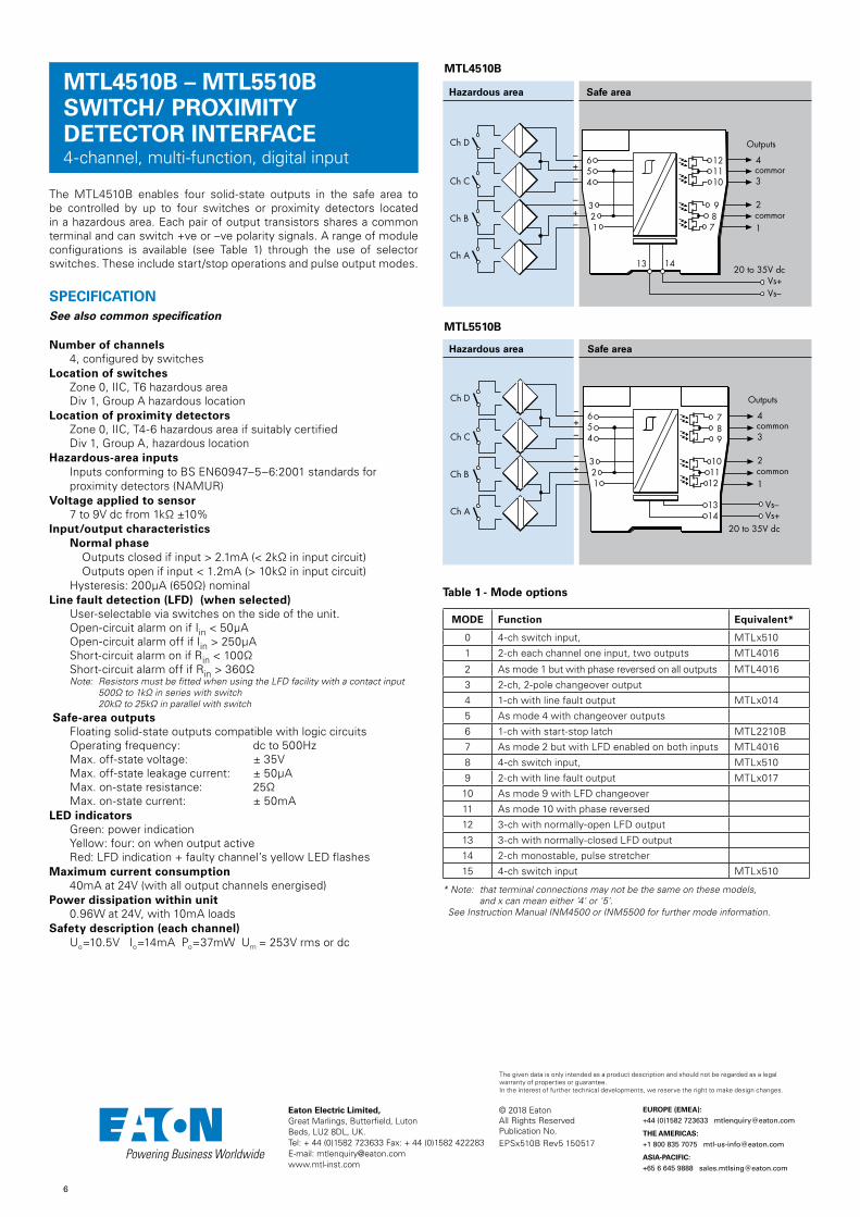
MTL4510B – MTL5510B SWITCH/ PROXIMITY DETECTOR INTERFACE4-channel, multi-function, digital input
The MTL4510B enables four solid-state outputs in the safe area to be controlled by up to four switches or proximity detectors located in a hazardous area. Each pair of output transistors shares a common terminal and can switch +ve or –ve polarity signals. A range of module configurations is available (see Table 1) through the use of selector switches. These include start/stop operations and pulse output modes.
SPECIFICATIONSee also common specification
Number of channels4, configured by switches
Location of switchesZone 0, IIC, T6 hazardous areaDiv 1, Group A hazardous location
Location of proximity detectorsZone 0, IIC, T4-6 hazardous area if suitably certifiedDiv 1, Group A, hazardous location
Hazardous-area inputsInputs conforming to BS EN60947–5–6:2001 standards for proximity detectors (NAMUR)
Voltage applied to sensor7 to 9V dc from 1kΩ ±10%
Input/output characteristicsNormal phase Outputs closed if input > 2.1mA (< 2kΩ in input circuit) Outputs open if input < 1.2mA (> 10kΩ in input circuit)Hysteresis: 200µA (650Ω) nominal
Line fault detection (LFD) (when selected)User-selectable via switches on the side of the unit. Open-circuit alarm on if Iin < 50µAOpen-circuit alarm off if Iin > 250µAShort-circuit alarm on if Rin < 100ΩShort-circuit alarm off if Rin > 360ΩNote: Resistors must be fitted when using the LFD facility with a contact input
500Ω to 1kΩ in series with switch 20kΩ to 25kΩ in parallel with switch
Safe-area outputs Floating solid-state outputs compatible with logic circuitsOperating frequency: dc to 500HzMax. off-state voltage: ± 35VMax. off-state leakage current: ± 50µAMax. on-state resistance: 25ΩMax. on-state current: ± 50mA
LED indicatorsGreen: power indicationYellow: four: on when output activeRed: LFD indication + faulty channel’s yellow LED flashes
Maximum current consumption 40mA at 24V (with all output channels energised)
Power dissipation within unit0.96W at 24V, with 10mA loads
Safety description (each channel)Uo=10.5V Io=14mA Po=37mW Um = 253V rms or dc
Table 1 - Mode options
MODE Function Equivalent*
0 4-ch switch input, MTLx510
1 2-ch each channel one input, two outputs MTL4016
2 As mode 1 but with phase reversed on all outputs MTL4016
3 2-ch, 2-pole changeover output
4 1-ch with line fault output MTLx014
5 As mode 4 with changeover outputs
6 1-ch with start-stop latch MTL2210B
7 As mode 2 but with LFD enabled on both inputs MTL4016
8 4-ch switch input, MTLx510
9 2-ch with line fault output MTLx017
10 As mode 9 with LFD changeover
11 As mode 10 with phase reversed
12 3-ch with normally-open LFD output
13 3-ch with normally-closed LFD output
14 2-ch monostable, pulse stretcher
15 4-ch switch input MTLx510
* Note: that terminal connections may not be the same on these models, and x can mean either '4' or '5'.
See Instruction Manual INM4500 or INM5500 for further mode information.
Hazardous area Safe area
Ch B
Vs–Vs+
20 to 35V dc
–+–
–+–
Ch D
Ch C
Ch A
1
2
3
4
common
common
Outputs
654
321
789
101112
1314
MTL5510B
MTL4510B
Hazardous area Safe area
Ch B –+–
–+–
Ch D
Ch C
Ch A
1
2
3
4
common
common
Outputs
Vs–Vs+
20 to 35V dc
654
321
987
121110
13 14
EPSx510B Rev5 150517

7
© 2018 EatonAll Rights ReservedPublication No.
Eaton Electric Limited, Great Marlings, Butterfield, LutonBeds, LU2 8DL, UK.Tel: + 44 (0)1582 723633 Fax: + 44 (0)1582 422283E-mail: [email protected]
EUROPE (EMEA):
+44 (0)1582 723633 [email protected]
THE AMERICAS:
+1 800 835 7075 [email protected]
ASIA-PACIFIC:
+65 6 645 9888 [email protected]
The given data is only intended as a product description and should not be regarded as a legal warranty of properties or guarantee. In the interest of further technical developments, we reserve the right to make design changes.
MTL4511 – MTL5511 SWITCH/ PROXIMITY DETECTOR INTERFACE1-channel, with line fault detection
The MTLx511 enables a safe-area load to be controlled by a switch or proximity detector located in a hazardous-area. When selected, open or short circuit conditions in the field wiring are detected by the line-fault-detect (LFD) facility and also indicated on the top of the module. Phase reversal for the channel is selected by a switch on the side of the module and output is provided by changeover relay contacts.
SPECIFICATION See also common specification
Number of channelsOne
Location of switchesZone 0, IIC, T6 hazardous areaDiv. 1, Group A hazardous location
Location of proximity detectorZone 0, IIC, T4–6 hazardous area if suitably certifiedDiv. 1, Group A hazardous location
Hazardous-area inputsInputs conforming to BS EN60947–5–6:2001 standards for proximity detectors (NAMUR)
Voltage applied to sensor7 to 9V dc from 1kΩ ±10%
Input/output characteristicsNormal phase Outputs closed if input > 2.1mA (< 2kΩ in input circuit) Outputs open if input < 1.2mA (> 10kΩ in input circuit)Hysteresis: 200µA (650Ω) nominal
Line fault detection (LFD) (when selected)User-selectable via switches on the side of the unit. A line fault is indicated by an LED. The channel output relay is de-energised if an input line fault is detected.Open-circuit alarm on if Iin < 50µAOpen-circuit alarm off if Iin > 250µAShort-circuit alarm on if Rin < 100ΩShort-circuit alarm off if Rin > 360ΩNote: Resistors must be fitted when using the LFD facility with a contact input
500Ω to 1kΩ in series with switch 20kΩ to 25kΩ in parallel with switch
Safe-area output Single pole relay with changeover contacts
Note: reactive loads must be adequately suppressed
Relay characteristics
MTL4511 MTL5511
Response time: 10ms maximum 10ms maximum
Contact rating (Safe Area):
10W, 0.5A, 35V dc
250V ac, 2A, cosØ >0.7, 40V dc, 2A, resistive load
Contact rating (Zone 2):
10W, 0.5A, 35V dc
35V, 2A, 100VA.
LED indicatorsGreen: power indicationYellow: channel status, on when output energisedRed: LFD indication, on when line fault detected
Maximum current consumption25mA at 24V
Power dissipation within unit0.6W at 24V
Safety description (each channel)Uo=10.5V Io=14mA Po=37mW Um = 253V rms or dc
SIL capableThese models have been assessed for use in IEC 61508 functional safety applications. SIL2 capable for a single device (HFT=0) SIL3 capable for multiple devices in safety redundant configurations (HFT=1) See data on MTL web site and refer to the safety manual.
Hazardous area Safe area
Vs–Vs+
20 to 35V dc
22kΩ
680Ω
+
–Output
Switch-type sensorsrequire resistorsif LFD is selected
654
321
789
101112
1314
MTL5511
MTL4511
Hazardous area Safe area
22kΩ
680Ω
+
–Output
Switch-type sensorsrequire resistorsif LFD is selected
Vs–Vs+
20 to 35V dc
654
321
987
121110
13 14
FSM FUNCTIONAL SAFETY
MANAGEMENT
IEC 61508:2010
EPSx511 Rev6 010916
SIL2
IEC 61508:2010
SIL3
IEC 61508:2010

8
© 2018 EatonAll Rights ReservedPublication No.
Eaton Electric Limited, Great Marlings, Butterfield, LutonBeds, LU2 8DL, UK.Tel: + 44 (0)1582 723633 Fax: + 44 (0)1582 422283E-mail: [email protected]
EUROPE (EMEA):
+44 (0)1582 723633 [email protected]
THE AMERICAS:
+1 800 835 7075 [email protected]
ASIA-PACIFIC:
+65 6 645 9888 [email protected]
The given data is only intended as a product description and should not be regarded as a legal warranty of properties or guarantee. In the interest of further technical developments, we reserve the right to make design changes.
The MTLx513 enables two solid-state outputs in the safe area to be controlled by two switches or proximity detectors located in the hazardous area. The Ch1/Ch2 output transistors share a common terminal and can switch +ve or -ve polarity signals. Independent output phase reversal and line fault detection are enabled via switches for each output. LFD indication is provided on the top of the module.
SPECIFICATIONSee also common specification
Number of channelsTwo
Location of switchesZone 0, IIC, T6 hazardous areaDiv. 1, Group A hazardous location
Location of proximity detectorsZone 0, IIC, T4–6 hazardous area if suitably certifiedDiv. 1, Group A hazardous location
Hazardous-area inputsInputs conforming to BS EN60947–5–6:2001 standards for proximity detectors (NAMUR)
Voltage applied to sensor7 to 9V dc from 1kΩ ±10%
Input/output characteristicsNormal phase Outputs closed if input > 2.1mA (< 2kΩ in input circuit) Outputs open if input < 1.2mA (> 10kΩ in input circuit)Hysteresis: 200µA (650Ω) nominal
Line fault detection (LFD) (when selected)User-selectable for each channel via switches on the side of the unit. Line faults are indicated by an LED for each channel. Open-circuit alarm on if Iin < 50µAOpen-circuit alarm off if Iin > 250µAShort-circuit alarm on if Rin < 100ΩShort-circuit alarm off if Rin > 360ΩNote: Resistors must be fitted when using the LFD facility with a contact input
500Ω to 1kΩ in series with switch 20kΩ to 25kΩ in parallel with switch
Phase reversalIndependent for each channel, user-selectable
Safe-area outputs Floating solid-state outputs compatible with logic circuitsOperating frequency: dc to 500HzMax. off-state voltage: ± 35VMax. off-state leakage current: ± 50µAMax. on-state resistance: 25ΩMax. on-state current: ± 50mA
MTL4513 – MTL5513 SWITCH/ PROXIMITY DETECTOR INTERFACE2-channel, line fault detection, phase reversal
LED indicatorsGreen: power indicationYellow: two: channel status, on when output activeRed: two: LFD indication, on when line fault detected
Maximum current consumption30mA at 24V
Power dissipation within unit0.65W typical at 24V, with 10mA loads0.78W max. with 50mA loads
Safety description (each channel)Uo=10.5V Io=14mA Po=37mW Um = 253V rms or dc
Hazardous area Safe area
Vs–Vs+
20 to 35V dc
Ch 1
Ch 2
Outputs
+–
22kΩ
680Ω
+–
Switch-type sensorsrequire resistorsif LFD is selected
22kΩ
680Ω
654
321
789
101112
1314
MTL5513
MTL4513
Hazardous area Safe area
Ch 1
Ch 2
Outputs
+–
22kΩ
680Ω
+
–
22kΩ
680Ω
Vs–Vs+
20 to 35V dcSwitch-type sensorsrequire resistors if LFD is selected
654
321
987
121110
13 14
EPSx513 Rev5 010916
9
© 2018 EatonAll Rights ReservedPublication No.
Eaton Electric Limited, Great Marlings, Butterfield, LutonBeds, LU2 8DL, UK.Tel: + 44 (0)1582 723633 Fax: + 44 (0)1582 422283E-mail: [email protected]
EUROPE (EMEA):
+44 (0)1582 723633 [email protected]
THE AMERICAS:
+1 800 835 7075 [email protected]
ASIA-PACIFIC:
+65 6 645 9888 [email protected]
The given data is only intended as a product description and should not be regarded as a legal warranty of properties or guarantee. In the interest of further technical developments, we reserve the right to make design changes.
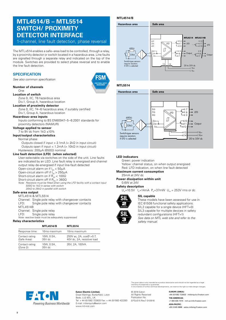
MTL4514/B – MTL5514SWITCH/ PROXIMITY DETECTOR INTERFACE1-channel, line fault detection, phase reversal
The MTLx514 enables a safe–area load to be controlled, through a relay, by a proximity detector or switch located in a hazardous area. Line faults are signalled through a separate relay and indicated on the top of the module. Switches are provided to select phase reversal and to enable the line fault detection.
SPECIFICATIONSee also common specification
Number of channelsOne
Location of switchZone 0, IIC, T6 hazardous areaDiv.1, Group A, hazardous location
Location of proximity detectorZone 0, IIC, T4–6 hazardous area, if suitably certifiedDiv.1, Group A, hazardous location
Hazardous–area inputsInputs conforming to BS EN60947–5–6:2001 standards for proximity detectors (NAMUR)
Voltage applied to sensor7 to 9V dc from 1kΩ ±10%
Input/output characteristicsNormal phase Outputs closed if input > 2.1mA (< 2kΩ in input circuit) Outputs open if input < 1.2mA (> 10kΩ in input circuit)Hysteresis: 200µA (650Ω) nominal
Line fault detection (LFD) (when selected)User-selectable via switches on the side of the unit. Line faults are indicated by an LED. Line fault relay is energised and channel output relay de-energised if input line-fault detectedOpen-circuit alarm on if Iin < 50µAOpen-circuit alarm off if Iin > 250µAShort-circuit alarm on if Rin < 100ΩShort-circuit alarm off if Rin > 360ΩNote: Resistors must be fitted when using the LFD facility with a contact input
500Ω to 1kΩ in series with switch 20kΩ to 25kΩ in parallel with switch
Safe-area output MTL4514 & MTL5514Channel: Single pole relay with changeover contactsLFD: Single pole relay with changeover contactsMTL4514BChannel: Single pole relayLFD: Single pole relay
Note: reactive loads must be adequately suppressedRelay characteristics
MTL4514/B MTL5514
Response time: 10ms maximum 10ms maximum
Contact rating (Safe Area):
10W, 0.5A, 35V dc
250V ac, 2A, cosØ >0.7, 40V dc, 2A, resistive load
Contact rating (Zone 2):
10W, 0.5A, 35V dc
35V, 2A, 100VA.
LED indicatorsGreen: power indicationYellow: channel status, on when output energisedRed: LFD indication, on when line fault detected
Maximum current consumption 25mA at 24V dc
Power dissipation within unit0.6W at 24V
Safety descriptionUo=10.5V Io=14mA Po=37mW Um = 253V rms or dc
SIL capableThese models have been assessed for use in IEC 61508 functional safety applications. SIL2 capable for a single device (HFT=0) SIL3 capable for multiple devices in safety redundant configurations (HFT=1) See data on MTL web site and refer to the safety manual.
Hazardous area Safe area
Vs–Vs+
20 to 35V dc
22kΩ
680Ω
+
–
Output
LFD
Switch-type sensorsrequire resistorsif LFD is selected
654
321
789
101112
1314
LFD
MTL5514
MTL4514/B
Hazardous area Safe area
FSM FUNCTIONAL SAFETY
MANAGEMENT
IEC 61508:2010
EPSx514 Rev7 010916
SIL2
IEC 61508:2010
SIL3
IEC 61508:2010
680Ω
+
–
Output
LFD
Switch-type sensorsrequire resistorsif LFD is selected
Vs–Vs+
20 to 35V dc
To earth-leakagedetector *
MTL4514 MTL4514B
LFD
Output
654
321
987
121110
LFD
987
121110
13 14
22kΩ

10
© 2018 EatonAll Rights ReservedPublication No.
Eaton Electric Limited, Great Marlings, Butterfield, LutonBeds, LU2 8DL, UK.Tel: + 44 (0)1582 723633 Fax: + 44 (0)1582 422283E-mail: [email protected]
EUROPE (EMEA):
+44 (0)1582 723633 [email protected]
THE AMERICAS:
+1 800 835 7075 [email protected]
ASIA-PACIFIC:
+65 6 645 9888 [email protected]
The given data is only intended as a product description and should not be regarded as a legal warranty of properties or guarantee. In the interest of further technical developments, we reserve the right to make design changes.
MTL4514D – MTL5514DSWITCH/ PROXIMITY DETECTOR INTERFACE1-channel, dual output, LFD, phase reversal
The MTLx514D enables two safe–area loads to be controlled, through relays, by a proximity detector or switch located in a hazardous area. When selected, open or short circuit conditions in the field wiring are detected by the line fault detect (LFD) facility and indicated on the top of the module. Switches are provided to select phase reversal and to enable the line fault detection.
SPECIFICATIONSee also common specification
Number of channelsOne
Location of switchZone 0, IIC, T6 hazardous areaDiv.1, Group A, hazardous location
Location of proximity detectorZone 0, IIC, T4–6 hazardous area, if suitably certifiedDiv.1, Group A, hazardous location
Hazardous–area inputsInputs conforming to BS EN60947–5–6:2001 standards for proximity detectors (NAMUR)
Voltage applied to sensor7 to 9V dc from 1kΩ ±10%
Input/output characteristicsNormal phase Outputs closed if input > 2.1mA (< 2kΩ in input circuit) Outputs open if input < 1.2mA (> 10kΩ in input circuit)Hysteresis: 200µA (650Ω) nominal
Line fault detection (LFD) (when selected)User-selectable via switches on the side of the unit. Line faults are indicated by an LED. The channel output relays are de-energised if an input line-fault is detectedOpen-circuit alarm on if Iin < 50µAOpen-circuit alarm off if Iin > 250µAShort-circuit alarm on if Rin < 100ΩShort-circuit alarm off if Rin > 360ΩNote: Resistors must be fitted when using the LFD facility with a contact input
500Ω to 1kΩ in series with switch 20kΩ to 25kΩ in parallel with switch
Safe-area output MTL4514D: two, single pole relays with normally-open contactsMTL5514D: two, single pole relays with changeover contacts
Note: reactive loads must be adequately suppressedRelay characteristics
MTL4514D MTL5514D
Response time: 10ms maximum 10ms maximum
Contact rating (Safe Area):
10W, 0.5A, 35V dc
250V ac, 2A, cosØ >0.7, 40V dc, 2A, resistive load
Contact rating (Zone 2):
10W, 0.5A, 35V dc
35V, 2A, 100VA.
LED indicatorsGreen: power indicationYellow: channel status, on when output energisedRed: LFD indication, on when line fault detected
Maximum current consumption 29mA at 24V dc
Power dissipation within unit0.7W at 24V
Safety descriptionUo=10.5V Io=14mA Po=37mW Um = 253V rms or dc
SIL capableThese models have been assessed for use in IEC 61508 functional safety applications. SIL2 capable for a single device (HFT=0) SIL3 capable for multiple devices in safety redundant configurations (HFT=1) See data on MTL web site and refer to the safety manual
Hazardous area Safe area
Vs–Vs+
20 to 35V dc
22kΩ
680Ω
+
–
Output 1
Switch-type sensorsrequire resistorsif LFD is selected
Output 2654
321
789
101112
1314
MTL5514D
MTL4514D
Hazardous area Safe area
22kΩ
680Ω
+
–Output 1
Switch-type sensorsrequire resistorsif LFD is selected
Vs–Vs+
20 to 35V dc
To earth-leakage detector * Output 2
654
321
987
121110
13 14
FSM FUNCTIONAL SAFETY
MANAGEMENT
IEC 61508:2010
EPSx514D Rev3 010916
SIL2
IEC 61508:2010
SIL3
IEC 61508:2010

11
© 2018 EatonAll Rights ReservedPublication No.
Eaton Electric Limited, Great Marlings, Butterfield, LutonBeds, LU2 8DL, UK.Tel: + 44 (0)1582 723633 Fax: + 44 (0)1582 422283E-mail: [email protected]
EUROPE (EMEA):
+44 (0)1582 723633 [email protected]
THE AMERICAS:
+1 800 835 7075 [email protected]
ASIA-PACIFIC:
+65 6 645 9888 [email protected]
The given data is only intended as a product description and should not be regarded as a legal warranty of properties or guarantee. In the interest of further technical developments, we reserve the right to make design changes.
MTL4514NSWITCH/ PROXIMITY DETECTOR INTERFACE1-channel, line fault detection, phase reversal
The MTL4514N enables a safe–area load to be controlled, through a relay, by a proximity detector or switch located in a hazardous area. Line faults are signalled through a separate relay and indicated on the top of the module. Switches are provided to select phase reversal and to enable the line fault detection. Resistors, fitted in series with the relay contacts, and when connectors in parallel, permit LFD pass-through to the system input.
SPECIFICATIONSee also common specification
Number of channelsOne
Location of switchZone 0, IIC, T6 hazardous areaDiv.1, Group A, hazardous location
Location of proximity detectorZone 0, IIC, T4–6 hazardous area, if suitably certifiedDiv.1, Group A, hazardous location
Hazardous–area inputsInputs conforming to BS EN60947–5–6:2001 standards for proximity detectors (NAMUR)
Voltage applied to sensor7 to 9V dc from 1kΩ ±10%
Input/output characteristicsNormal phase Outputs closed if input > 2.1mA (< 2kΩ in input circuit) Outputs open if input < 1.2mA (> 10kΩ in input circuit)Hysteresis: 200µA (650Ω) nominal
Line fault detection (LFD) (when selected)User-selectable via switches on the side of the unit. Line faults are indicated by an LED. Line fault relay is de-energised and channel output relay de-energised if input line-fault detectedOpen-circuit alarm on if Iin < 50µAOpen-circuit alarm off if Iin > 250µAShort-circuit alarm on if Rin < 100ΩShort-circuit alarm off if Rin > 360ΩNote: Resistors must be fitted when using the LFD facility with a contact input
500Ω to 1kΩ in series with switch 20kΩ to 25kΩ in parallel with switch
Safe-area output Channel: Single pole relay in series with 2k2Ω resistorLFD: Single pole relay in series with 15kΩ resistorNote: reactive loads must be adequately suppressed
Relay characteristics
MTL4514N
Response time: 10ms maximum
Contact rating (Safe Area):
10W, 0.5A, 35V dc
Contact rating (Zone 2):
10W, 0.5A, 35V dc
ID Resistor18kΩ
LED indicatorsGreen: power indicationYellow: channel status, on when output energisedRed: LFD indication, on when line fault detected
Maximum current consumption 25mA at 24V dc
Power dissipation within unit0.6W at 24V
Safety descriptionUo=10.5V Io=14mA Po=37mW Um = 253V rms or dc
SIL capableThese models have been assessed for use in IEC 61508 functional safety applications. SIL2 capable for a single device (HFT=0) SIL3 capable for multiple devices in safety redundant configurations (HFT=1) See data on MTL web site and refer to the safety manual.
MTL4514N
Hazardous area Safe area
22kΩ
680Ω
+
–
Output
LFD
Switch-type sensorsrequire resistorsif LFD is selected
Vs–Vs+
20 to 35V dc
To earth-leakage detector *
ID654
321
LFD
987
121110
13 14
15K
2K2
FSM FUNCTIONAL SAFETY
MANAGEMENT
IEC 61508:2010
SIL2
IEC 61508:2010
SIL3
IEC 61508:2010
EPS4514N Rev4 240517

12
© 2018 EatonAll Rights ReservedPublication No.
Eaton Electric Limited, Great Marlings, Butterfield, LutonBeds, LU2 8DL, UK.Tel: + 44 (0)1582 723633 Fax: + 44 (0)1582 422283E-mail: [email protected]
EUROPE (EMEA):
+44 (0)1582 723633 [email protected]
THE AMERICAS:
+1 800 835 7075 [email protected]
ASIA-PACIFIC:
+65 6 645 9888 [email protected]
The given data is only intended as a product description and should not be regarded as a legal warranty of properties or guarantee. In the interest of further technical developments, we reserve the right to make design changes.
MTL5514-TSWITCH/ PROXIMITY DETECTOR INTERFACE1-channel, line fault detection, phase reversal
The MTL5514-T enables a safe–area load to be controlled, through a relay, by a proximity detector or switch located in a hazardous area. Line faults are signalled through a separate relay and indicated on the top of the module. Switches are provided to select phase reversal and to enable the line fault detection.
SPECIFICATIONSee also common specification
Number of channelsOne
Location of switchZone 0, IIC, T6 hazardous areaDiv.1, Group A, hazardous location
Location of proximity detectorZone 0, IIC, T4–6 hazardous area, if suitably certifiedDiv.1, Group A, hazardous location
Hazardous–area inputsInputs conforming to BS EN60947–5–6:2001 standards for proximity detectors (NAMUR)
Voltage applied to sensor7 to 9V dc from 1kΩ ±10%
Input/output characteristicsNormal phase Outputs closed if input > 2.1mA (< 2kΩ in input circuit) Outputs open if input < 1.2mA (> 10kΩ in input circuit)Hysteresis: 200µA (650Ω) nominal
Line fault detection (LFD) (when selected)User-selectable via switches on the side of the unit. Line faults are indicated by an LED. Line fault relay is energised and channel output relay de-energised if input line-fault detectedOpen-circuit alarm on if Iin < 50µAOpen-circuit alarm off if Iin > 250µAShort-circuit alarm on if Rin < 100ΩShort-circuit alarm off if Rin > 360ΩNote: Resistors must be fitted when using the LFD facility with a contact input
500Ω to 1kΩ in series with switch 20kΩ to 25kΩ in parallel with switch
Safe-area output Channel: Single pole relay with changeover contactsLFD: Single pole relay with changeover contacts
Note: reactive loads must be adequately suppressed
Relay characteristics
MTL5514-T
Response time: 10ms maximum
Contact rating (Safe Area):
250V ac, 2A, cosØ >0.7, 40V dc, 2A, resistive load
LED indicatorsGreen: power indicationYellow: channel status, on when output energisedRed: LFD indication, on when line fault detected
Maximum current consumption 25mA at 24V dc
Power dissipation within unit0.6W at 24V
Operating temperature range -20°C to + 65°C (-6 to + 149°F)
Safety descriptionUo=10.5V Io=14mA Po=37mW Um = 253V rms or dc
Hazardous area Safe area
Vs–Vs+
20 to 35V dc
22kΩ
680Ω
+
–
Output
LFD
Switch-type sensorsrequire resistorsif LFD is selected
654
321
789
101112
1314
LFD
MTL5514-T
EPS5514-T Rev1 230118

13
© 2018 EatonAll Rights ReservedPublication No.
Eaton Electric Limited, Great Marlings, Butterfield, LutonBeds, LU2 8DL, UK.Tel: + 44 (0)1582 723633 Fax: + 44 (0)1582 422283E-mail: [email protected]
EUROPE (EMEA):
+44 (0)1582 723633 [email protected]
THE AMERICAS:
+1 800 835 7075 [email protected]
ASIA-PACIFIC:
+65 6 645 9888 [email protected]
The given data is only intended as a product description and should not be regarded as a legal warranty of properties or guarantee. In the interest of further technical developments, we reserve the right to make design changes.
MTL4516/C – MTL5516C SWITCH/ PROXIMITY DETECTOR INTERFACE2-channel, with line fault detection
The MTLx516/C enable two safe-area loads to be controlled by a switch or proximity detector located in a hazardous-area. When selected, open or short circuit conditions in the field wiring are detected by the line-fault-detect (LFD) facility and also indicated on the top of the module. Phase reversal for each channel is selected by a switch on the side of the module and output is provided by changeover relay contacts.
SPECIFICATIONSee also common specification
Number of channelsTwo
Location of switchesZone 0, IIC, T6 hazardous areaDiv. 1, Group A hazardous location
Location of proximity detectorZone 0, IIC, T4–6 hazardous area if suitably certifiedDiv. 1, Group A hazardous location
Hazardous-area inputsInputs conforming to BS EN60947–5–6:2001 standards for proximity detectors (NAMUR)
Voltage applied to sensor7 to 9V dc from 1kΩ ±10%
Input/output characteristicsNormal phase Outputs closed if input > 2.1mA (< 2kΩ in input circuit) Outputs open if input < 1.2mA (> 10kΩ in input circuit)Hysteresis: 200µA (650Ω) nominal
Line fault detection (LFD) (when selected)User-selectable via switches on the side of the unit. Line faults are indicated by an LED for each channel. The channel output relay is de-energised if an input line fault is detected.Open-circuit alarm on if Iin < 50µAOpen-circuit alarm off if Iin > 250µAShort-circuit alarm on if Rin < 100ΩShort-circuit alarm off if Rin > 360ΩNote: Resistors must be fitted when using the LFD facility with a contact input
500Ω to 1kΩ in series with switch 20kΩ to 25kΩ in parallel with switch
Safe-area output Two single-pole relays with changeover contacts
Note: reactive loads must be adequately suppressedRelay characteristics
MTL4516/C MTL5516C
Response time: 10ms maximum 10ms maximum
Contact rating (Safe Area):
10W, 0.5A, 35V dc
250V ac, 2A, cosØ >0.7, 40V dc, 2A, resistive load
Contact rating (Zone 2):
10W, 0.5A, 35V dc
35V, 2A, 100VA.
Maximum current consumption35mA at 24V
Power dissipation within unit0.84W at 24V
LED indicatorsGreen: power indicationYellow: two: channel status, on when output energisedRed: two: LFD indication, on when line fault detected
Safety description (each channel)Uo=10.5V Io=14mA Po=37mW Um = 253V rms or dc
SIL capableThese models have been assessed for use in IEC 61508 functional safety applications. SIL2 capable for a single device (HFT=0) SIL3 capable for multiple devices in safety redundant configurations (HFT=1) See data on MTL web site and refer to the safety manual
Hazardous area Safe area
Vs–Vs+
20 to 35V dc
+–
+
–Ch 2
Ch 1
22kΩ
680Ω
22kΩ
680Ω
Switch-type sensorsrequire resistorsif LFD is selected
654
321
789
101112
1314
MTL5516C
MTL4516C
Hazardous area Safe area
+–
+
–Ch 2
Ch 1
22kΩ
680Ω
22kΩ
680Ω
Vs–Vs+
20 to 35V dcSwitch-type sensorsrequire resistorsif LFD is selected
654
321
987
121110
13 14
MTL4516
Hazardous area Safe area
22kΩ
680Ω+–
22kΩ
680Ω
+–
Ch 2
Ch 1
Switch-type sensorsrequire resistorsif LFD is selected
Vs–Vs+
20 to 35V dc
654
321
987
121110
13 14
FSM FUNCTIONAL SAFETY
MANAGEMENT
IEC 61508:2010
EPSx516/C Rev6 010916
SIL2
IEC 61508:2010
SIL3
IEC 61508:2010

14
© 2018 EatonAll Rights ReservedPublication No.
Eaton Electric Limited, Great Marlings, Butterfield, LutonBeds, LU2 8DL, UK.Tel: + 44 (0)1582 723633 Fax: + 44 (0)1582 422283E-mail: [email protected]
EUROPE (EMEA):
+44 (0)1582 723633 [email protected]
THE AMERICAS:
+1 800 835 7075 [email protected]
ASIA-PACIFIC:
+65 6 645 9888 [email protected]
The given data is only intended as a product description and should not be regarded as a legal warranty of properties or guarantee. In the interest of further technical developments, we reserve the right to make design changes.
MTL4517 – MTL5517 SWITCH/ PROXIMITY DETECTOR INTERFACE2-channel, line fault detection, phase reversal
The MTLx517 enables two safe-area loads to be controlled, through a relay, by proximity detectors or switches located in a hazardous area. Line faults are signalled through a separate relay and indicated on the top of the module. Switches are provided to select phase reversal and to enable the line fault detection.
SPECIFICATIONSee also common specification
Number of channelsTwo
Location of switchZone 0, IIC, T6 hazardous areaDiv.1, Group A, hazardous location
Location of proximity detectorZone 0, IIC, T4–6 hazardous area, if suitably certifiedDiv.1, Group A, hazardous location
Hazardous-area inputsInputs conforming to BS EN60947–5–6:2001 standards for proximity detectors (NAMUR)
Voltage applied to sensor7 to 9V dc from 1kΩ ±10%
Input/output characteristicsNormal phase Outputs closed if input > 2.1mA (< 2kΩ in input circuit) Outputs open if input < 1.2mA (> 10kΩ in input circuit)Hysteresis: 200µA (650Ω) nominal
Line fault detection (LFD) (when selected)User selectable by switches on the side of the module. Line faults are indicated by the LED for each channel.Line fault relay is energised and channel output relay de-energised if input line-fault detectedOpen-circuit alarm on if Iin < 50µAOpen-circuit alarm off if Iin > 250µAShort-circuit alarm on if Rin < 100ΩShort-circuit alarm off if Rin > 360ΩNote: Resistors must be fitted when using the LFD facility with a contact input
500Ω to 1kΩ in series with switch 20kΩ to 25kΩ in parallel with switch
Safe-area output Channel: Two single-pole relays with normally open contactsLFD: Single pole relay with changeover contact (MTL4517) Single pole relay with normally open contact (MTL5517)
Note: reactive loads must be adequately suppressedRelay characteristics
MTL4517 MTL5517
Response time: 10ms maximum 10ms maximum
Contact rating (Safe Area):
10W, 0.5A, 35V dc
250V ac, 2A, cosØ >0.7, 40V dc, 2A, resistive load
Contact rating (Zone 2):
10W, 0.5A, 35V dc
35V, 2A, 100VA.
Maximum current consumption35mA at 24V
Power dissipation within unit0.84W at 24V
LED indicatorsGreen: power indicationYellow: two: channel status, on when output energisedRed: two: LFD indication, on when line fault detected
Safety description (each channel)Uo=10.5V Io=14mA Po=37mW Um = 253V rms or dc
SIL capableThese models have been assessed for use in IEC 61508 functional safety applications. SIL2 capable for a single device (HFT=0) SIL3 capable for multiple devices in safety redundant configurations (HFT=1) See data on MTL web site and refer to the safety manual.
Hazardous area Safe area
Vs–Vs+
20 to 35V dc
LFD
+–
+
–
Switch-type sensorsrequire resistorsif LFD is selected
Ch 2
Ch 1
LFD
22kΩ
680Ω
22kΩ
680Ω
654
321
789
101112
1314
LFD
MTL5517
MTL4517
Hazardous area Safe area
LFD
+–
+
–
Switch-type sensorsrequire resistorsif LFD is selected
122kΩ
680Ω
22kΩ
680Ω
Vs–Vs+
20 to 35V dc
2
654
321
LFD
987
121110
13 14
FSM FUNCTIONAL SAFETY
MANAGEMENT
IEC 61508:2010
EPSx517 Rev6 010916
SIL2
IEC 61508:2010
SIL3
IEC 61508:2010

15
© 2018 EatonAll Rights ReservedPublication No.
Eaton Electric Limited, Great Marlings, Butterfield, LutonBeds, LU2 8DL, UK.Tel: + 44 (0)1582 723633 Fax: + 44 (0)1582 422283E-mail: [email protected]
EUROPE (EMEA):
+44 (0)1582 723633 [email protected]
THE AMERICAS:
+1 800 835 7075 [email protected]
ASIA-PACIFIC:
+65 6 645 9888 [email protected]
The given data is only intended as a product description and should not be regarded as a legal warranty of properties or guarantee. In the interest of further technical developments, we reserve the right to make design changes.
MTL4521/L – MTL5521 SOLENOID/ ALARM DRIVERloop-powered, IIC
The MTLx521 and the MTL4521L are loop-powered modules which enable a device located in the hazardous area to be controlled from the safe area. They can all drive a certified intrinsically safe low-power load, as well as non-energy-storing simple apparatus such as an LED.
SPECIFICATIONSee also common specification
Number of channelsOne
Location of loadZone 0, IIC, T4–6 hazardous area if suitably certifiedDiv. 1, Group A hazardous location
Minimum output voltage Equivalent output circuit(MTLx521)
22.2
22.2
13.6
Minimum output voltage Equivalent output circuit(MTL4521L)
48Output current (mA)
Outputvoltage(V)
22.2V minimum
232Ω
maximum
Current limit: 48mA
22.2
11.1
Input voltage20 to 35V dc
Hazardous-area output (MTLx521)Minimum output voltage: 13.6V at 48mAMaximum output voltage: 24V from 180ΩCurrent limit: 48mA minimum
Hazardous-area output (MTL4521L)Minimum output voltage: 11.1V at 48mAMaximum output voltage: 24V from 232ΩCurrent limit: 48mA minimum
Output ripple< 0.5% of maximum output, peak to peak
Response timeOutput within 10% of final value within 100ms
LED indicatorYellow: output status, on when output active
Maximum current consumption 90mA at 24V
Power dissipation within unit1.4W at 24V
Safety description (MTLx521)Uo=25V Io=147mA Po=0.92W Um = 253V rms or dc
Safety description (MTL4521L)Uo= 25V Io= 108mA Po= 0.68W Um = 253V rms or dc
SIL capableThese models have been assessed for use in IEC 61508 functional safety applications. SIL3 capable for a single device (HFT=0) when the required function is to de-energise the output. SIL1 capable for a single device (HFT=0) when the required function is to energise the output.See data on MTL web site and refer to the safety manual.
Hazardous area Safe area
654
321
789
101112
1314
Solenoid, alarm or other IS device
20 – 35Vdc–+
+
–
MTL5521
MTL4521 / MTL4521L
Hazardous area Safe area
FSM FUNCTIONAL SAFETY
MANAGEMENT
IEC 61508:2010
EPSx521 Rev8 040517
SIL3
IEC 61508:2010
SIL1
IEC 61508:2010

16
© 2018 EatonAll Rights ReservedPublication No.
Eaton Electric Limited, Great Marlings, Butterfield, LutonBeds, LU2 8DL, UK.Tel: + 44 (0)1582 723633 Fax: + 44 (0)1582 422283E-mail: [email protected]
EUROPE (EMEA):
+44 (0)1582 723633 [email protected]
THE AMERICAS:
+1 800 835 7075 [email protected]
ASIA-PACIFIC:
+65 6 645 9888 [email protected]
The given data is only intended as a product description and should not be regarded as a legal warranty of properties or guarantee. In the interest of further technical developments, we reserve the right to make design changes.
MTL5521-T SOLENOID/ ALARM DRIVERloop-powered, IIC
The MTL5521 is aloop-powered module which enables a device located in the hazardous area to be controlled from the safe area. That can drive a certified intrinsically safe low-power load, as well as non-energy-storing simple apparatus such as an LED.
SPECIFICATIONSee also common specification
Number of channelsOne
Location of loadZone 0, IIC, T4–6 hazardous area if suitably certifiedDiv. 1, Group A hazardous location
Minimum output voltage Equivalent output circuit(MTL5521)
22.2
22.2
13.6
Input voltage20 to 35V dc
Hazardous-area outputMinimum output voltage: 13.6V at 48mAMaximum output voltage: 24V from 180ΩCurrent limit: 48mA minimum
Output ripple< 0.5% of maximum output, peak to peak
Response timeOutput within 10% of final value within 100ms
LED indicatorYellow: output status, on when output active
Maximum current consumption 90mA at 24V
Power dissipation within unit1.4W at 24V
Operating temperature range -20°C to + 65°C (-6 to + 149°F) Safety description (MTLx521) Uo=25V Io=147mA Po=0.92W Um = 253V rms or dc
Hazardous area Safe area
654
321
789
101112
1314
Solenoid, alarm or other IS device
20 – 35Vdc–+
+
–
MTL5521
EPS5521-T Rev1 230118

17
© 2018 EatonAll Rights ReservedPublication No.
Eaton Electric Limited, Great Marlings, Butterfield, LutonBeds, LU2 8DL, UK.Tel: + 44 (0)1582 723633 Fax: + 44 (0)1582 422283E-mail: [email protected]
EUROPE (EMEA):
+44 (0)1582 723633 [email protected]
THE AMERICAS:
+1 800 835 7075 [email protected]
ASIA-PACIFIC:
+65 6 645 9888 [email protected]
The given data is only intended as a product description and should not be regarded as a legal warranty of properties or guarantee. In the interest of further technical developments, we reserve the right to make design changes.
MTL5522 SOLENOID/ALARM DRIVERloop-powered, IIB
The MTL5522 is a loop-powered module which enables a device located in the hazardous area to be controlled from the safe area. The MTL5522 can drive a certified intrinsically safe low-power load, as well as non-energy-storing simple apparatus such as an LED. The unit's input/output isolation allows the control switch to be connected into either side of the 24V dc supply circuit.
SPECIFICATIONSee also common specification
Number of channelsOne
Location of loadZone 0, IIB, T4–6 hazardous area if suitably certifiedDiv. 1, Group C hazardous location
Minimum output voltage Equivalent output circuit
70Output current (mA)
Outputvoltage(V)
22.2
10.7 22.2V minimum
158Ω maximum
Current limit: 70mA
Input voltage20 to 35V dc
Hazardous-area outputMinimum output voltage: 10.7V at 70mAMaximum output voltage: 24V from 158ΩCurrent limit: 70mA minimum
Output ripple< 0.5% of maximum output, peak to peak
Response timeOutput within 10% of final value within 100ms
LED indicatorYellow: output status, on when output active
Maximum current consumption 125mA (typ.) at 24V
Power dissipation within unit1.4W at 24V
Safety descriptionUo=25V Io=166mA Po=1.04W Um = 253V rms or dc
SIL capableThese models have been assessed for use in IEC 61508 functional safety applications. SIL3 capable for a single device (HFT=0) when the required function is to de-energise the output. SIL1 capable for a single device (HFT=0) when the required function is to energise the output.See data on MTL web site and refer to the safety manual.
Hazardous area Safe area
654
321
789
101112
1314
Solenoid, alarm or other IS device
20 – 35Vdc–+
+
–
MTL5522
FSM FUNCTIONAL SAFETY
MANAGEMENT
IEC 61508:2010
EPSx522 Rev8 040517
SIL3
IEC 61508:2010
SIL1
IEC 61508:2010

18
© 2018 EatonAll Rights ReservedPublication No.
Eaton Electric Limited, Great Marlings, Butterfield, LutonBeds, LU2 8DL, UK.Tel: + 44 (0)1582 723633 Fax: + 44 (0)1582 422283E-mail: [email protected]
EUROPE (EMEA):
+44 (0)1582 723633 [email protected]
THE AMERICAS:
+1 800 835 7075 [email protected]
ASIA-PACIFIC:
+65 6 645 9888 [email protected]
The given data is only intended as a product description and should not be regarded as a legal warranty of properties or guarantee. In the interest of further technical developments, we reserve the right to make design changes.
With the MTLx523 interface, an on/off device in a hazardous area can be controlled by a volt-free contact or logic signal in the safe area. It is suitable for driving loads such as solenoids. Line fault detection (LFD), which operates irrespective of the output state, is signalled by a safe-area solid-state switch which de-energises MTLx523, or energises MTL4523R, if a field line is open or short–circuited. Earth fault detection can be provided by connecting an MTL4220 earth leakage detector to terminal 3.
SPECIFICATIONSee also common specification
Number of channelsOne
Location of loadZone 0, IIC, T4–6 hazardous area if suitably certifiedDiv. 1, Group A, hazardous location
Minimum output voltage Equivalent output circuit
22.2
22.2
13.6
Hazardous-area outputMinimum output voltage: 13.6V at 48mAMaximum output voltage: 24V from 180ΩMaximum off-state output voltage: 4V from 180ΩCurrent limit: 48mA minimum
Output ripple< 0.5% of maximum output, peak to peak
Control inputSuitable for switch contacts, an open collector transistor or logic drive. (Internal contact wetting voltage 12V @ 0.2mA contact closed. Not suitable for voltage control via series diode.)Output turns on if input switch closed, transistor on or < 1.4V applied across control inputOutput turns off if input switch open, transistor off or > 4.5V applied across control input
Response timeOutput within 10% of final value within 100ms
Line fault detection (LFD)Open or short circuit in field cabling de-energises* solid state line-fault signal. LFD transistor is switched on*, provided that the field circuit impedance is > 55Ω and < 4kΩ. * These conditions are reversed for the MTL4523R. This is to permit parallel connection of alarms between modules to provide a group alarm output.
Line fault signal characteristicsMaximum off-state voltage: 35VMaximum off-state leakage current: 10µAMaximum on-state voltage drop: 2VMaximum on-state current: 50mA
LED indicatorsGreen: power indicationYellow: output status, on when output activeRed: LFD indication, on when line fault detected
Maximum current consumption100mA at 24V dc
Power dissipation within unit1.2W with typical solenoid valve, output on2.0W worst case
Safety descriptionUo=25V Io=147mA Po= 0.92W Um = 253V rms or dc
SIL capableThese models have been assessed for use in IEC 61508 functional safety applications. SIL2 capable for a single device (HFT=0) SIL3 capable for multiple devices in safety redundant configurations (HFT=1) See data on MTL web site and refer to the safety manual.
Hazardous area Safe area
654
321
789
101112
1314
Solenoid, alarm or other IS device
+
–
Vs–Vs+
20 to 35V dc
+–
LFD
+
‡
‡ link to reverse output phase
Control
MTL5523
MTL4523 / MTL4523R
Hazardous area Safe area
654
321
Solenoid, alarm orother IS device
+
–
+
–
LFD†
† MTL4523RLFD phase reversed
Vs–Vs+
20 to 35V dc
Control
+
–987
121110
13 14
FSM FUNCTIONAL SAFETY
MANAGEMENT
IEC 61508:2010
MTL4523/R – MTL5523 SOLENOID/ALARM DRIVERwith line fault detection, IIC
EPSx523/R Rev9 040517
SIL2
IEC 61508:2010
SIL3
IEC 61508:2010

19
© 2018 EatonAll Rights ReservedPublication No.
Eaton Electric Limited, Great Marlings, Butterfield, LutonBeds, LU2 8DL, UK.Tel: + 44 (0)1582 723633 Fax: + 44 (0)1582 422283E-mail: [email protected]
EUROPE (EMEA):
+44 (0)1582 723633 [email protected]
THE AMERICAS:
+1 800 835 7075 [email protected]
ASIA-PACIFIC:
+65 6 645 9888 [email protected]
The given data is only intended as a product description and should not be regarded as a legal warranty of properties or guarantee. In the interest of further technical developments, we reserve the right to make design changes.
With the MTL4523L interface, an on/off device in a hazardous area can be controlled by a voltage signal in the safe area. It is suitable for driving loads such as solenoids. Line fault detection (LFD), which operates when the output is energised, is signalled by a safe-area solid-state switch which energises if a field line is open or short-circuited. Earth fault detection can be provided by connecting an MTL4220 earth leakage detector to terminal 3.
SPECIFICATIONSee also common specification
Number of channelsOne
Location of loadZone 0, IIC, T4–6 hazardous area if suitably certifiedDiv. 1, Group A, hazardous location
Minimum output voltage Equivalent output circuit
22.2
22.2
13.6
Input voltage20 to 35V dc
Hazardous-area outputMinimum output voltage: 13.6V at 48mAMaximum output voltage: 24V from 180ΩCurrent limit: 48mA minimum
Output ripple< 0.5% of maximum output, peak to peak
Response timeOutput within 10% of final value within 100ms
Line fault detection (LFD)Open or short circuit in field cabling energises solid state line fault signal LFD transistor is switched on, provided that the field circuit impedance is > 55Ω and < 4kΩ.
Line fault signal characteristicsMaximum off-state voltage: 35VMaximum off-state leakage current: 10µAMaximum on-state voltage drop: 2VMaximum on-state current: 50mA
Note: LFD signal is Zener-diode protected against inductive loads
MTL4523L SOLENOID/ ALARM DRIVERloop-powered with line fault detection, IIC
LED indicatorsYellow: output status, on when output activeRed: LFD indication, on when line fault detected
Maximum current consumption100mA at 24V dc
Power dissipation within unit1.2W with typical solenoid valve, output on
Safety descriptionUo=25V Io=147mA Po= 0.92W Um = 253V rms or dc
SIL capableThese models have been assessed for use in IEC 61508 functional safety applications. SIL3 capable for a single device (HFT=0) when the required function is to de-energise the output. SIL1 capable for a single device (HFT=0) when the required function is to energise the output.See data on MTL web site and refer to the safety manual.
MTL4523L
Hazardous area Safe area
654
321
Solenoid, alarm orother IS device
+
–LFD
Vs–Vs+
20 to 35V dc
+
–987
121110
13 14
FSM FUNCTIONAL SAFETY
MANAGEMENT
IEC 61508:2010
EPS4523L Rev10 040517
SIL3
IEC 61508:2010
SIL1
IEC 61508:2010

20
© 2018 EatonAll Rights ReservedPublication No.
Eaton Electric Limited, Great Marlings, Butterfield, LutonBeds, LU2 8DL, UK.Tel: + 44 (0)1582 723633 Fax: + 44 (0)1582 422283E-mail: [email protected]
EUROPE (EMEA):
+44 (0)1582 723633 [email protected]
THE AMERICAS:
+1 800 835 7075 [email protected]
ASIA-PACIFIC:
+65 6 645 9888 [email protected]
The given data is only intended as a product description and should not be regarded as a legal warranty of properties or guarantee. In the interest of further technical developments, we reserve the right to make design changes.
With the MTLx523V/VL interface, an on/off device in a hazardous area can be controlled by a voltage signal in the safe area. It is suitable for driving loads such as solenoids. Line fault detection (LFD), which operates irrespective of the output state, is signalled by a safe-area solid-state switch which energises if a field line is open or short–circuited. Earth fault detection can be provided by connecting an MTL4220 earth leakage detector to terminal 3.
SPECIFICATIONSee also common specification
Number of channelsOne
Location of loadZone 0, IIC, T4–6 hazardous area if suitably certifiedDiv. 1, Group A, hazardous location
Minimum output voltage Equivalent output circuit(MTLx523V)
22.2
22.2
13.6
Minimum output voltage Equivalent output circuit(MTLx523VL)
48Output current (mA)
Outputvoltage(V)
22.2V minimum
232Ω
maximum
Current limit: 48mA
22.2
11.1
Hazardous-area output (MTLx523V)Minimum output voltage: 13.6V at 48mAMaximum output voltage: 24V from 180ΩMaximum off-state output voltage: 4V from 180ΩCurrent limit: 48mA minimum
Hazardous-area output (MTLx523VL)Minimum output voltage: 11.1V at 48mAMaximum output voltage: 24V from 232ΩMaximum off-state output voltage: 4V from 232ΩCurrent limit: 48mA minimum
Output ripple< 0.5% of maximum output, peak to peak
Control inputSuitable for 24V logic driveOutput turns on if > 18V applied across control inputOutput turns off if < 5V applied across control inputMaximum control input voltage: 28VMaximum control system output leakage current: 0.5mA
Response timeOutput within 10% of final value within 100ms
MTL4523V/VL – MTL5523V/VL SOLENOID/ALARM DRIVERwith line fault detection, IIC
Line fault detection (LFD)Open or short circuit in field cabling energises solid state line-fault signal. LFD transistor is switched off, provided that the field circuit impedance is > 55Ω and < 4kΩ.
Line fault signal characteristicsMaximum off-state voltage: 35VMaximum off-state leakage current: 10µAMaximum on-state voltage drop: 2VMaximum on-state current: 50mA
LED indicatorsGreen: power indicationYellow: output status, on when output activeRed: LFD indication, on when line fault detected
Maximum current consumption100mA at 24V dc
Power dissipation within unit1.2W with typical solenoid valve, output on2.0W worst case
Safety description (MTLx523V)Vo=25V Io=147mA Po= 0.92W Um = 253V rms or dc
Safety description (MTLx523VL)Vo=25V Io=108mA Po= 0.68W Um = 253V rms or dc
SIL capableThese models have been assessed for use in IEC 61508 functional safety applications. SIL2 capable for a single device (HFT=0) SIL3 capable for multiple devices in safety redundant configurations (HFT=1) See data on MTL web site and refer to the safety manual.
Hazardous area Safe area
654
321
789
101112
1314
Solenoid, alarm or other IS device
+
–
Vs–Vs+
20 to 35V dc
+–
LFD
+
ControlV
MTL5523V/MTL5523VL
MTL4523V/MTL4523VL
Hazardous area Safe area
654
321
Solenoid, alarm orother IS device
+
–
+
–
LFD
Vs–Vs+
20 to 35V dc
Control
+
–987
121110
13 14
V
FSM FUNCTIONAL SAFETY
MANAGEMENT
IEC 61508:2010
EPSx523V-VL Rev6 040517
SIL2
IEC 61508:2010
SIL3
IEC 61508:2010

21
© 2018 EatonAll Rights ReservedPublication No.
Eaton Electric Limited, Great Marlings, Butterfield, LutonBeds, LU2 8DL, UK.Tel: + 44 (0)1582 723633 Fax: + 44 (0)1582 422283E-mail: [email protected]
EUROPE (EMEA):
+44 (0)1582 723633 [email protected]
THE AMERICAS:
+1 800 835 7075 [email protected]
ASIA-PACIFIC:
+65 6 645 9888 [email protected]
The given data is only intended as a product description and should not be regarded as a legal warranty of properties or guarantee. In the interest of further technical developments, we reserve the right to make design changes.
MTL4524 – MTL5524 SOLENOID/ALARM DRIVERswitch operated with override, IIC
The MTLx524 enables an on/off device in a hazardous area to be controlled by a volt-free contact or logic signal in the safe area. It can drive loads such as solenoids, alarms, LEDs and other low power devices that are certified as intrinsically safe or are classified as non-energy storing simple apparatus.
The MTL4524 allows a second safe-area switch or logic signal to be connected enabling the output to be disabled to permit, for example, a safety system to override a control signal.
The MTL5524 has its phase reversed by connecting a wire link between pins 8 and 9.
SPECIFICATIONSee also common specification
Number of channelsOne
Location of loadZone 0, IIC, T4–6 hazardous area if suitably certified Div.1, Group A, hazardous location
Minimum output voltage Equivalent output circuit
22.2
22.2
13.6
Hazardous-area outputMinimum output voltage: 13.6V at 48mAMaximum output voltage: 24V from 180ΩMaximum off-state output voltage: 4V from 180ΩCurrent limit: 48mA minimum
Output ripple< 0.5% of maximum output, peak-to-peak
Control inputSuitable for switch contacts, an open collector transistor or logic drive0 = input switch closed, transistor on or <1.4V applied1 = input switch open, transistor off or >4.5V applied
Override input on MTL4524 An open collector transistor or a switch connected across the terminals can be used to turn the output off whatever the state of the control input 0 = transistor on or switch closed1 = transistor off or switch open
Control and override inputs on MTL4524
Control input Override input Output state
0 0 off
0 1 on
1 0 off
1 1 off
Response timeOutput within 10% of final value within 100ms
LED indicatorsGreen: power indicationYellow: output status, on when output active
Maximum current consumption100mA at 24V dc
Power dissipation within unit1.3W with typical solenoid valve, output on1.9W worst case
Safety descriptionUo=25V Io=147mA Po= 0.92W Um = 253V rms or dc
SIL capableThese models have been assessed for use in IEC 61508 functional safety applications. SIL2 capable for a single device (HFT=0) SIL3 capable for multiple devices in safety redundant configurations (HFT=1) See data on MTL web site and refer to the safety manual.
MTL4524
Hazardous area Safe area
654
321
Solenoid, alarm orother IS device
+
–
+
–
Vs–Vs+
20 to 35V dc
Control
+
–
Override
987
121110
13 14
MTL5524
Hazardous area Safe area
654
321
789
101112
1314
Solenoid, alarm or other IS device
+
–
Vs–Vs+
20 to 35V dc
+–
Control‡
‡ use link to reverse phase
FSM FUNCTIONAL SAFETY
MANAGEMENT
IEC 61508:2010
EPSx524 Rev8 040517
SIL2
IEC 61508:2010
SIL3
IEC 61508:2010

22
© 2018 EatonAll Rights ReservedPublication No.
Eaton Electric Limited, Great Marlings, Butterfield, LutonBeds, LU2 8DL, UK.Tel: + 44 (0)1582 723633 Fax: + 44 (0)1582 422283E-mail: [email protected]
EUROPE (EMEA):
+44 (0)1582 723633 [email protected]
THE AMERICAS:
+1 800 835 7075 [email protected]
ASIA-PACIFIC:
+65 6 645 9888 [email protected]
The given data is only intended as a product description and should not be regarded as a legal warranty of properties or guarantee. In the interest of further technical developments, we reserve the right to make design changes.
MTL4524S SOLENOID/ALARM DRIVERswitch operated with 24V override, IIC
The MTL4524S enables an on/off device in a hazardous area to be controlled by a volt-free contact or a floating logic signal in the safe area. It can drive loads such as solenoids, alarms, LEDs and other low power devices that are certified as intrinsically safe or are classified as non-energy storing simple apparatus. By connecting a second safe-area voltage, the output can be disabled to permit, for example, a safety system to override a control signal.
SPECIFICATIONSee also common specification
Number of channelsOne
Location of loadZone 0, IIC, T4–6 hazardous area if suitably certified Div.1, Group A, hazardous location
Minimum output voltage Equivalent output circuit
22.2
22.2
13.6
Hazardous-area outputMinimum output voltage: 13.6V at 48mAMaximum output voltage: 24V from 180ΩMaximum off-state output voltage: 4V from 180ΩCurrent limit: 48mA minimum
Output ripple< 0.5% of maximum output, peak-to-peak
Control input (must be fully-floating)Suitable for switch contacts or an opto-isolator0 = input switch closed, transistor on or < 1.4V applied1 = input switch open, transistor off or > 4.5V applied
Override input A 24V logic signal applied across the terminals allows the solenoid/alarm to be operated by the control input. If it is disconnected, the solenoid/alarm is off.0 = < 2.0V applied across terminals 8 & 91 = > 9.0V applied across terminals 8 & 9 (nominal switching point 4.5V)
Control and override inputs
Control input Override input Output state
0 0 off
0 1 on
1 0 off
1 1 off
Response timeOutput within 10% of final value within 100ms
LED indicatorsGreen: power indicationYellow: output status, on when output active
Maximum current consumption100mA at 24V dc
Power dissipation within unit1.3W with typical solenoid valve, output on1.9W worst case
Safety descriptionUo=25V Io=147mA Po= 0.92W Um = 253V rms or dc
SIL capableThese models have been assessed for use in IEC 61508 functional safety applications. SIL2 capable for a single device (HFT=0) SIL3 capable for multiple devices in safety redundant configurations (HFT=1) See data on MTL web site and refer to the safety manual.
MTL4524S
Hazardous area Safe area
654
321
Solenoid, alarm orother IS device
+
–
+
–
Vs–Vs+
20 to 35V dc
Control
+
–
Override
24V
987
121110
13 14
FSM FUNCTIONAL SAFETY
MANAGEMENT
IEC 61508:2010
EPS4524S Rev6 040517
SIL2
IEC 61508:2010
SIL3
IEC 61508:2010

23
© 2018 EatonAll Rights ReservedPublication No.
Eaton Electric Limited, Great Marlings, Butterfield, LutonBeds, LU2 8DL, UK.Tel: + 44 (0)1582 723633 Fax: + 44 (0)1582 422283E-mail: [email protected]
EUROPE (EMEA):
+44 (0)1582 723633 [email protected]
THE AMERICAS:
+1 800 835 7075 [email protected]
ASIA-PACIFIC:
+65 6 645 9888 [email protected]
The given data is only intended as a product description and should not be regarded as a legal warranty of properties or guarantee. In the interest of further technical developments, we reserve the right to make design changes.
MTL4525 – MTL5525 SOLENOID/ALARM DRIVERswitch operated with override, IIC, low power
The MTLx525 enables an on/off device in a hazardous area to be controlled by a volt-free contact or logic signal in the safe area. It can drive loads such as solenoids, alarms, LEDs and other low power devices that are certified as intrinsically safe or are classified as non-energy storing simple apparatus.
The MTL4525 allows a second safe-area switch or logic signal to be connected that enables the output to be disabled to permit, for example, a safety system to override a control signal.
SPECIFICATIONSee also common specification
Number of channelsOne
Location of loadZone 0, IIC, T4–6 hazardous area if suitably certified Div.1, Group A, hazardous location
Minimum output voltage Equivalent output circuit
22.2
22.27.8
Hazardous-area outputMinimum output voltage: 7.8V at 48mAMaximum output voltage: 24V from 300ΩMaximum off-state output voltage: 4V from 300ΩCurrent limit: 48mA minimum
Output ripple< 0.5% of maximum output, peak-to-peak
Control input on MTL4525Suitable for switch contacts, an open collector transistor or logic drive0 = input switch closed, transistor on or < 1.4V applied1 = input switch open, transistor off or > 4.5V applied
Override input on MTL4525An open collector transistor or a switch connected across the terminals can be used to turn the output off whatever the state of the control input 0 = transistor on or switch closed1 = transistor off or switch open
Control and override inputs on MTL4525
Control input Override input Output state
0 0 off
0 1 on
1 0 off
1 1 off
Response timeOutput within 10% of final value within 100ms
LED indicatorsGreen: power indicationYellow: output status, on when output active
Maximum current consumption 100mA at 24V dc
Power dissipation within unit1.3W with typical solenoid valve, output on1.9W worst case
Safety descriptionUo=25V Io=83.3mA Po=0.52W Um = 253V rms or dc
SIL capableThese models have been assessed for use in IEC 61508 functional safety applications. SIL2 (SIL3 for MTL5525) capable for a single device (HFT=0) SIL3 capable for multiple devices in safety redundant configurations (HFT=1) See data on MTL web site and refer to the safety manual.
MTL4525
Hazardous area Safe area
654
321
Solenoid, alarm orother IS device
+
–
+
–
Vs–Vs+
20 to 35V dc
Control
+
–
Override
987
121110
13 14
MTL5525
Hazardous area Safe area
654
321
789
101112
1314
Solenoid, alarm or other IS device
20 – 35Vdc–+
+
–
FSM FUNCTIONAL SAFETY
MANAGEMENT
IEC 61508:2010
EPSx525 Rev8 040517
SIL2
IEC 61508:2010
SIL3
IEC 61508:2010

24
© 2018 EatonAll Rights ReservedPublication No.
Eaton Electric Limited, Great Marlings, Butterfield, LutonBeds, LU2 8DL, UK.Tel: + 44 (0)1582 723633 Fax: + 44 (0)1582 422283E-mail: [email protected]
EUROPE (EMEA):
+44 (0)1582 723633 [email protected]
THE AMERICAS:
+1 800 835 7075 [email protected]
ASIA-PACIFIC:
+65 6 645 9888 [email protected]
The given data is only intended as a product description and should not be regarded as a legal warranty of properties or guarantee. In the interest of further technical developments, we reserve the right to make design changes.
MTL4526 – MTL5526 SWITCH-OPERATED RELAY2–channel IS–output
The MTLx526 enables two separate IS circuits in a hazardous area to be contact controlled by one or two, on/off, control signals in a safe area. Applications include the calibration of strain–gauge bridges; changing the polarity (and thereby the tone) of an IS sounder; the testing of IS fire alarms; and the transfer of safe-area signals into an annunciator with IS input terminals not segregated from each other. The output–relay contacts are certified as non–energy–storing apparatus, and can be connected to any IS circuit without further certification, provided that separate IS circuits are such that they would remain safe if connected together.
SPECIFICATIONSee also common specification
Number of channelsTwo, fully floating
Location of control circuitSafe area
Input/output characteristicsContact/Logic mode(Inputs suitable for switch contacts, an open–collector transistor or logic drive)Relay energised if < 450Ω or < 1V appliedRelay de–energised if > 5kΩ or > 2V applied (35V max.)Loop powered modeRelay energised if >20VRelay de-energised if <17V
Power supply failure protectionRelays de–energised if supply fails
Response time25ms nominal
Contacts (suitable for connection to IS circuits)1–pole changeover per channel
Contact rating250V ac, limited to 40V dc for IS applications, 2A(reactive loads must be suppressed)
Contact life expectancy2 x 107 operations at maximum IS load
Relay drive (see switch setting table) Choice of "loop-powered" or "contact/logic" control, for both channels, by switch selection. A further switch option ("1in2out") enables either input, in contact/logic mode, to activate both outputs.
LED indicatorsGreen: power indicationYellow: two: output status, on when relay energised
Power requirement, Vs41mA at 20V dc44mA at 24V dc60mA at 35V dc
Power dissipation within unit1.1W maximum at 24V
Safety description (each channel)Non-energy–storing apparatus: relay contacts may be connected to any IS circuit without further consideration
User switch settings for operating mode
Mode Function SW1 SW2 SW3 SW4
Contact/Logic
Input
2 ch Off On On On
1in2out On On On On
Loop Powered 2 ch Off Off Off Off
MTL4526
MTL5526
Hazardous area Safe area
123
456
IS relay
IS relay
1
2 +
–
+–
All contacts shown in normal position(relays de-energised)
Vs–Vs+
20 to 35V dc
+
–
+–
Control20 to 35V dc
Looppowered
Contactinputs
987
121110
1
2
Sw413 14
Hazardous area Safe area
123
456
789
101112
1314
IS relay
IS relay
1
Vs–Vs+
20 to 35V dc
+
–
2
+
–
Control20 to 35V dc
+–
+–
Looppowered
Contactinputs
All contacts shown in normal position(relays de-energised)
1
2
Sw4
EPSx526 Rev7 010916

25
© 2018 EatonAll Rights ReservedPublication No.
Eaton Electric Limited, Great Marlings, Butterfield, LutonBeds, LU2 8DL, UK.Tel: + 44 (0)1582 723633 Fax: + 44 (0)1582 422283E-mail: [email protected]
EUROPE (EMEA):
+44 (0)1582 723633 [email protected]
THE AMERICAS:
+1 800 835 7075 [email protected]
ASIA-PACIFIC:
+65 6 645 9888 [email protected]
The given data is only intended as a product description and should not be regarded as a legal warranty of properties or guarantee. In the interest of further technical developments, we reserve the right to make design changes.
SIL capableThese models have been assessed for use in IEC 61508 functional safety applications up to SIL 1. See data on MTL web site and refer to the safety manual.
The MTLx531 repeats a signal from a vibration sensor in a hazardous area, providing an output for a monitoring system in the safe area. The interface is compatible with 3-wire eddy-current probes and accelerometers or 2-wire current sensors; the selection is made by a switch on the side of the module.
SPECIFICATIONSee also common specification
Number of channelsOne
Sensor type2- or 3-wire vibration transducer
Location of signal sourceZone 0, IIC, T4–6 hazardous area if suitably certifiedDiv. 1, Group A hazardous location
Hazardous-area inputInput impedance (terminals 2 & 3): 10kΩ
Transducer supply voltage, 3-wire (terminals 3 & 1)
Output current –20mA
Outputvoltage
–24V
0
350Ω
–17V
Transducer supply current, 2-wire3.3mA (nom.) for 2-wire sensors, user selectable by switch
Signal range Minimum –20V, maximum –0.5V
DC transfer accuracy at 20°C<±50mV
AC transfer accuracy at 20°C0Hz to 1kHz: ±1%1kHz to 10kHz: –5% to +1%10kHz to 20kHz: –10% to +1%
Temperature coefficient±50ppm/°C (10 to 65°C)±100ppm/°C (–20 to 10°C)
Voltage bandwidth –3dB at 47kHz (typical)
Phase response<14µs, equivalent to:–1° at 200Hz–3° at 600Hz–5° at 1kHz–50° at 10kHz–100° at 20kHz
Safe-area output impedance <20Ω
LED indicatorGreen: power indication
Supply voltage20 to 35V dc
Maximum current consumption (10mA transducer load)65mA at 24V
Maximum power dissipation within unit 1.33W
Safety descriptionTerminals 3 to 1Uo=26.6V Io=94mA Po=0.66W Um = 253V rms or dc Terminals 3 to 2Non-energy-storing apparatus ≤1.5V, ≤0.1A and ≤25mW
MTL4531 – MTL5531 VIBRATION TRANSDUCER INTERFACE
Hazardous area Safe area
654
321
Vibrationtransducer
Vibrationtransducer
Vs–Vs+
20 to 35V dc
987
121110
13 14
Monitor
COMSIGV–
–ve
0V
3-wire
2-wire 2
1
3
MTL5531
MTL4531
Hazardous area Safe area
654
321
789
101112
1314
COMSIGV–
Vibrationtransducer
Vibrationtransducer
Vs–Vs+
20 to 35V dc
–ve
0VMonitor
3-wire
2-wire 2
1
3
SIL1
IEC 61508:2010
EPSx531 Rev9 210318

26
© 2018 EatonAll Rights ReservedPublication No.
Eaton Electric Limited, Great Marlings, Butterfield, LutonBeds, LU2 8DL, UK.Tel: + 44 (0)1582 723633 Fax: + 44 (0)1582 422283E-mail: [email protected]
EUROPE (EMEA):
+44 (0)1582 723633 [email protected]
THE AMERICAS:
+1 800 835 7075 [email protected]
ASIA-PACIFIC:
+65 6 645 9888 [email protected]
The given data is only intended as a product description and should not be regarded as a legal warranty of properties or guarantee. In the interest of further technical developments, we reserve the right to make design changes.
MTL4532 – MTL5532 PULSE ISOLATORpulse & 4/20mA current outputs
The MTLx532 isolates pulses from a switch, proximity detector, current pulse transmitter or voltage pulse transmitter located in a hazardous area. It is ideal for applications involving high pulse rates and fast response times, by repeating the pulses into the safe area. An analogue output proportional to frequency is also provided, together with a relay output, which may be configured to act as an alarm. Configuration is carried out with a personal computer.
SPECIFICATIONSee also common specification
Number of channelsOne, fully floating
Sensor typeSwitch or proximity detector (NAMUR/BS EN 60947–5–6:2001)2– or 3–wire voltage or pulse transmitter
Location of switchZone 0, IIC, T6 hazardous areaDiv. 1, Group A, hazardous location
Location of proximity detector or transmitterZone 0, IIC, T4–T6 if suitably certifiedDiv.1, Group A, hazardous location
InputSwitch input:Output ON if switch is closedProximity detector input:Excitation: 7.0 to 9.0V dc from 1kΩ nominalOutput ON if input > 2.1mA* (< 2kΩ) Output OFF if input < 1.2mA* (> 10kΩ) Switching hysteresis: 0.2mA (650Ω) nominal*NAMUR and BS EN 60947–5–6:2001standardsCurrent pulse input:Transmitter supply: 16.5V dc at 20mAShort circuit current: 24mAOutput: Iin > 9.0mA = ON, Iin < 7.0mA = OFFSwitching hysteresis: 0.5mAVoltage pulse inputInput impedance: > 10kΩSwitching point voltage (Vsp): 3, 6, or 12V nominal(User selectable by switches on the side of the module)Output: Vin > Vsp = ON, Vin < Vsp = OFFSwitching hysteresis: 100mV + (0.1 x Vsp) typical
Safe-area pulse output Maximum delay: 10µsMaximum off–state voltage: 35VMaximum off–state leakage current: 10µAMaximum on–state resistance: 25ΩMaximum on–state current: 50mAOutput OFF if supply fails
Note: LFD signal is Zener-diode protected against inductive loadsSafe-area current output
Input capture delay: 2 signal periods (5ms min.)Signal range: 4 to 20mAUnder/over range: 0 to 22mALoad resistance: 0 to 450Ω @20mAOutput resistance: >1MΩRipple: < 50µA peak-to-peakAccuracy: better than 20µA at 20°CTemperature drift: < 1µA/°CRisetime (10% - 90%, after step change): 60 ms
Alarm outputRelay ON in alarm, 0.5A @ 35Vdc max.
Pulse width High: 10µs minLow: 10µs min
Frequency range0 – 50kHz - pulse output mode0 – 10KHz - for analogue output
LED indicatorsGreen: power indicationYellow: on when output circuit is onRed: flashing when line fault or error
Power requirement65mA at 24V dc70mA at 20V dc55mA at 35V dc
Power dissipation within unit1.35W maximum at 24V1.75W maximum at 35V
Safety description (Um = 253V rms or dc)Terminals 2 to 1 and 6 to 1Uo=10.5V Io=14mA Po=37mWTerminals 4 to 3 and 1 Uo=28V Io=93mA Po=651mWTerminals 3 to 1Non-energy-storing apparatus ≤1.5V, ≤0.1A and ≤25mW; can be connected without further certification into any IS loop with an open-circuit voltage <28VTerminals 5 to 4 and 1Vmax ≤ 28V, Imax ≤ 94mA, Pmax ≤ 0.66W
ConfiguratorA personal computer running MTL PCS45 software with a PCL45USB serial interface.
Hazardous area Safe area
654
321
4/20mA
3-wirecurrentpulse
4/20mA
–
+
3-wirevoltagepulse
54
1
2-wirecurrentpulse
Voltagepulse
Currentpulse
5
1
Inhibit
Load
Alarm
4/20mA
Configurationsocket
–
+
1
4
+Pulse
–
+
Pulse
Vs–Vs+
20 to 35V dc4
3
V4/20mA
3
1
3 987
121110
13 14
Hazardous area Safe area
654
321
789
101112
1314
Vs–Vs+
20 to 35V dc
3-wirecurrentpulse
4/20mA
–
+
3-wirevoltagepulse
54
1
2-wirecurrentpulse
Voltagepulse
Currentpulse
5
1
Inhibit
Load
Alarm
4/20mA
Configurationsocket
–
+
1
4
+Pulse
–
+
Pulse
4
3
V4/20mA
3
1
3
4/20mA
MTL5532
MTL4532
EPSx532 Rev5 010916

27
© 2018 EatonAll Rights ReservedPublication No.
Eaton Electric Limited, Great Marlings, Butterfield, LutonBeds, LU2 8DL, UK.Tel: + 44 (0)1582 723633 Fax: + 44 (0)1582 422283E-mail: [email protected]
EUROPE (EMEA):
+44 (0)1582 723633 [email protected]
THE AMERICAS:
+1 800 835 7075 [email protected]
ASIA-PACIFIC:
+65 6 645 9888 [email protected]
The given data is only intended as a product description and should not be regarded as a legal warranty of properties or guarantee. In the interest of further technical developments, we reserve the right to make design changes.
MTL4541/S – MTL5541/S REPEATER POWER SUPPLY4/20mA, HART®, 2- or 3-wire transmitters
The MTLx541 provides a fully-floating dc supply for energising a conventional 2- or 3-wire 4/20mA transmitter, which is located in a hazardous area, and repeats the current in another floating circuit to drive a safe-area load. For HART 2-wire transmitters, the unit allows bi-directional communications signals superimposed on the 4/20mA loop current. Alternatively, the MTLx541S acts as a current sink for a safe-area connection rather than driving a current into the load. Separately powered current sources, such as 4-wire transmitters, can be connected but will not support HART communication.
SPECIFICATIONSee also common specification
Number of channelsOne
Location of transmitterZone 0, IIC, T4–6 hazardous area if suitably certifiedDiv. 1, Group A hazardous location
Safe-area output Signal range: 4 to 20mAUnder/over-range: 0 to 24mASafe-area load resistance (MTLx541) @ 24mA: 0 to 360Ω @ 20mA: 0 to 450ΩSafe-area load (MTLx541S) Current sink: 600Ω max. Maximum voltage source: 24V dcSafe-area circuit output resistance: > 1MΩ
Safe-area circuit ripple< 50µA peak-to-peak
Hazardous-area inputSignal range: 0 to 24mA (including over-range)Transmitter voltage: 16.5V at 20mA
Transfer accuracy at 20°CBetter than 15µA
Temperature drift< 0.8µA/°C
Response timeSettles to within 10% of final value within 50µs
Communications supportedHART (terminals 1 & 2 only)
LED indicatorGreen: power indication
Maximum current consumption (with 20mA signal)51mA at 24V
Power dissipation within unit (with 20mA signal)MTLx541 0.7W @ 24V dcMTLx541S 1.0W @ 24V dc
Safety descriptionTerminals 2 to 1 and 3:Uo=28V Io=93mA Po=651mW Um = 253V rms or dcTerminals 1 to 3:Simple apparatus ≤1.5V, ≤0.1A and ≤25mW; can be connected without further certification into any IS loop with an open-circuit voltage <28V
MTL4541 / MTL4541S
Hazardous area Safe area
654
321
4/20mA
MTL4541 MTL4541S
+
Vs–Vs+
20 to 35V dc
–4/20mA
Load
Load
+
––
+
ComTx+
Input
I
I987
121110
13 14
MTL5541 / MTL5541S
Hazardous area Safe area
654
321
789
101112
1314
Vs–Vs+
20 to 35V dc
4/20mA
MTL5541 MTL5541S
–4/20mA
Load+ Load
+
––
+ComTx+
Input
I
I
SIL capableThese models have been assessed for use in IEC 61508 functional safety applications. SIL3 capable for a single device (HFT=0) See data on MTL web site and refer to the safety manual.
SIL3
IEC 61508:2010
EPSx541/S Rev7 150817

28
© 2018 EatonAll Rights ReservedPublication No.
Eaton Electric Limited, Great Marlings, Butterfield, LutonBeds, LU2 8DL, UK.Tel: + 44 (0)1582 723633 Fax: + 44 (0)1582 422283E-mail: [email protected]
EUROPE (EMEA):
+44 (0)1582 723633 [email protected]
THE AMERICAS:
+1 800 835 7075 [email protected]
ASIA-PACIFIC:
+65 6 645 9888 [email protected]
The given data is only intended as a product description and should not be regarded as a legal warranty of properties or guarantee. In the interest of further technical developments, we reserve the right to make design changes.
MTL4541A/AS – MTL5541A/AS CURRENT REPEATER4/20mA passive i/p for HART® transmitters
The MTLx541A provides an input for separately powered 4/20mA transmitters and also allows bi–directional transmission of HART communication signals superimposed on the 4/20mA loop current. Alternatively, the MTLx541AS acts as a current sink for a safe-area connection rather than driving a current into the load.
SPECIFICATIONSee also common specification
Number of channelsOne
Location of transmitterZone 0, IIC, T4–6 hazardous area if suitably certified Div.1, Group A, hazardous location
Hazardous area inputSignal range: 4 to 20mAUnder/over-range: 1.0 to 21.5mA
Input impedance for HART signalsat terminals 1, 2: > 230Ω
Maximum input volt dropat terminals 1, 2: < 6.6Vi.e. a transmitter load of 330Ω at 20mA
Safe-area output Signal range: 4 to 20mAUnder/over-range: 1.0 to 21.5mASafe-area load resistance (MTLx541A) Conventional transmitters: 0 to 360Ω Smart transmitters: 250Ω ±10%Safe-area load (MTLx541AS) Current sink: 600Ω max. Maximum voltage source: 24V DCSafe-area circuit output resistance: > 1MΩ
Safe–area circuit ripple< 50µA peak-to-peak up to 80kHz
Transfer accuracy at 20°CBetter than 20µA
Temperature drift< 1µA/°C
Response timeSettles within 200µA of final value after 20ms
Communications supportedHART
LED indicatorGreen: power indication
Power requirement (with 20mA signal) 50mA at 20V45mA at 24V35mA at 35V
Power dissipation within unit (with 20mA signals)MTLx541A 0.8W @ 24V dc MTLx541AS 1.1W @ 24V dc
Safety descriptionTerminals 1 to 2:Um = 253V rms or dc.8.6V (diode). This voltage must be considered when calculating the load capacitance.Non-energy-storing apparatus ≤1.5V, ≤0.1A and ≤25mW; can be connected without further certification into any IS loop with an open-circuit voltage <28V
MTL4541A / MTL4541AS
Hazardous area Safe area
–4/20mA
Load+
–
+
MTL4541A MTL4541AS
Load
+
––
+
Vs–Vs+
20 to 35V dc
4/20mA
654
321
I
I987
121110
13 14
MTL5541A / MTL5541AS
Hazardous area Safe area
Vs–Vs+
20 to 35V dc
–4/20mA
Load+
MTL5541A MTL5541AS
Load
+
––
+
–
+4/20mA
654
321
789
101112
1314
I
I
EPSx541A/AS Rev5 010916
FSM FUNCTIONAL SAFETY
MANAGEMENT
IEC 61508:2010
SIL capableThese models have been assessed for use in IEC 61508 functional safety applications. SIL2 capable for a single device (HFT=0) SIL3 capable for multiple devices in safety redundant configurations (HFT=1) See data on MTL web site and refer to the safety manual.
SIL2
IEC 61508:2010
SIL3
IEC 61508:2010

29
© 2018 EatonAll Rights ReservedPublication No.
Eaton Electric Limited, Great Marlings, Butterfield, LutonBeds, LU2 8DL, UK.Tel: + 44 (0)1582 723633 Fax: + 44 (0)1582 422283E-mail: [email protected]
EUROPE (EMEA):
+44 (0)1582 723633 [email protected]
THE AMERICAS:
+1 800 835 7075 [email protected]
ASIA-PACIFIC:
+65 6 645 9888 [email protected]
The given data is only intended as a product description and should not be regarded as a legal warranty of properties or guarantee. In the interest of further technical developments, we reserve the right to make design changes.
MTL4541T REPEATER POWER SUPPLY4/20mA, 2- or 3-wire transmitters using long field lines
The MTL4541T provides a fully-floating dc supply for energising a conventional 2- or 3-wire 4/20mA transmitter, which is located in a hazardous area, and repeats the current in another floating circuit to drive a safe-area load. For HART 2-wire transmitters, the unit allows bi-directional communications signals superimposed on the 4/20mA loop current. Separately powered current sources, such as 4-wire transmitters, can be connected but will not support HART communication. The reduced maximum open-circuit voltage permits the use of longer field lines compared to MTL4541.
SPECIFICATIONSee also common specification
Number of channelsOne
Location of transmitterZone 0, IIC, T4–6 hazardous area if suitably certifiedDiv. 1, Group A hazardous location
Safe-area output Signal range: 4 to 20mAUnder/over-range: 0 to 24mASafe-area load resistance @ 24mA: 0 to 250Ω @ 20mA: 0 to 325Ω
Safe-area circuit ripple< 50µA peak-to-peak
Hazardous-area inputSignal range: 0 to 24mA (including over-range) Transmitter voltage: 14V at 20mA
Transfer accuracy at 20°CBetter than 15µA
Temperature drift< 0.8µA/°C
Response timeSettles to within 10% of final value within 50µs
Communications supportedHART (terminals 1 & 2 only)
LED indicatorGreen: power indication
Maximum current consumption (with 20mA signal)51mA at 24V
Power dissipation within unit (with 20mA signal)0.7W @ 24V dc
Safety descriptionTerminals 2 to 1:Vo=22V Io=167mA Po=920mW Um = 253V rms or dcTerminals 3 to 1:Simple apparatus ≤1.5V, ≤0.1A and ≤25mW; can be connected without further certification into any IS loop with an open-circuit voltage <28V
MTL4541T
Hazardous area Safe area
654
321
+–
4/20mA
+
Vs–Vs+
20 to 35V dc
–4/20mA
Load
I
I987
121110
13 14
EPS4541T Rev2 010916

30
© 2018 EatonAll Rights ReservedPublication No.
Eaton Electric Limited, Great Marlings, Butterfield, LutonBeds, LU2 8DL, UK.Tel: + 44 (0)1582 723633 Fax: + 44 (0)1582 422283E-mail: [email protected]
EUROPE (EMEA):
+44 (0)1582 723633 [email protected]
THE AMERICAS:
+1 800 835 7075 [email protected]
ASIA-PACIFIC:
+65 6 645 9888 [email protected]
The given data is only intended as a product description and should not be regarded as a legal warranty of properties or guarantee. In the interest of further technical developments, we reserve the right to make design changes.
MTL5541/S -T REPEATER POWER SUPPLY4/20mA, HART®, 2- or 3-wire transmitters
The MTL5541-T provides a fully-floating dc supply for energising a conventional 2- or 3-wire 4/20mA transmitter, which is located in a hazardous area, and repeats the current in another floating circuit to drive a safe-area load. For HART 2-wire transmitters, the unit allows bi-directional communications signals superimposed on the 4/20mA loop current. Alternatively, the MTL5541S-T acts as a current sink for a safe-area connection rather than driving a current into the load. Separately powered current sources, such as 4-wire transmitters, can be connected but will not support HART communication.
SPECIFICATIONSee also common specification
Number of channelsOne
Location of transmitterZone 0, IIC, T4–6 hazardous area if suitably certifiedDiv. 1, Group A hazardous location
Safe-area output Signal range: 4 to 20mAUnder/over-range: 0 to 24mASafe-area load resistance (MTL5541-T) @ 24mA: 0 to 360Ω @ 20mA: 0 to 450ΩSafe-area load (MTL5541S-T) Current sink: 600Ω max. Maximum voltage source: 24V dcSafe-area circuit output resistance: > 1MΩ
Safe-area circuit ripple< 50µA peak-to-peak
Hazardous-area inputSignal range: 0 to 24mA (including over-range)Transmitter voltage: 16.5V at 20mA
Transfer accuracy at 20°CBetter than 15µA
Temperature drift< 0.8µA/°C
Response timeSettles to within 10% of final value within 50µs
Communications supportedHART (terminals 1 & 2 only)
LED indicatorGreen: power indication
Maximum current consumption (with 20mA signal)51mA at 24V
Power dissipation within unit (with 20mA signal)MTL5541-T 0.7W @ 24V dcMTL5541S-T 1.0W @ 24V dc
Safety descriptionTerminals 2 to 1 and 3:Uo=28V Io=93mA Po=651mW Um = 253V rms or dcTerminals 1 to 3:Simple apparatus ≤1.5V, ≤0.1A and ≤25mW; can be connected without further certification into any IS loop with an open-circuit voltage <28V
Ambient temperature limits-20°C to + 65°C (-6 to + 149°F) operating-40°C to + 80°C (-40 to + 176°F) storage
MTL5541-T / MTL5541S-T
Hazardous area Safe area
654
321
789
101112
1314
Vs–Vs+
20 to 35V dc
4/20mA
MTL5541 MTL5541S
–4/20mA
Load+ Load
+
––
+ComTx+
Input
I
I
EPS5541/S-T Rev1 230118

31
© 2018 EatonAll Rights ReservedPublication No.
Eaton Electric Limited, Great Marlings, Butterfield, LutonBeds, LU2 8DL, UK.Tel: + 44 (0)1582 723633 Fax: + 44 (0)1582 422283E-mail: [email protected]
EUROPE (EMEA):
+44 (0)1582 723633 [email protected]
THE AMERICAS:
+1 800 835 7075 [email protected]
ASIA-PACIFIC:
+65 6 645 9888 [email protected]
The given data is only intended as a product description and should not be regarded as a legal warranty of properties or guarantee. In the interest of further technical developments, we reserve the right to make design changes.
The MTLx544 provides fully-floating dc supplies for energising two conventional 2-wire or 3-wire 4/20mA or HART transmitters located in a hazardous area, and repeats the current in other circuits to drive two safe-area loads. For smart transmitters, the unit allows bi-directional transmission of digital communication signals superimposed on the 4/20mA loop current. Alternatively, the MTLx544S acts as a current sink for a safe-area connection rather than driving a current into the load. Separately powered current sources, such as 4-wire transmitters, can be connected but will not support HART communication.
SPECIFICATIONSee also common specification
Number of channelsTwo
Location of transmitterZone 0, IIC, T4–6 hazardous area if suitably certifiedDiv. 1, Group A hazardous location
Safe-area output Signal range: 4 to 20mAUnder/over-range: 0 to 24mASafe-area load resistance (MTLx 544) @ 24mA: 0 to 360Ω @ 20mA: 0 to 450ΩSafe-area load (MTLx544S) Current sink: 600Ω max. Maximum voltage source: 24V dcSafe-area circuit output resistance: > 1MΩ
Safe-area circuit ripple< 50µA peak-to-peak
Hazardous-area inputSignal range: 0 to 24mA (including over-range) Transmitter voltage: 16.5V at 20mA
Transfer accuracy at 20°CBetter than 15µA
Temperature drift< 0.8µA/°C
Response timeSettles to within 10% of final value within 50µs
Communications supportedHART (terminals 1 & 2 and 4 & 5 only)
MTL4544/S – MTL5544/S REPEATER POWER SUPPLY2-channel, 4/20mA, HART®, 2- or 3- wire transmitters
Hazardous area Safe area
Vs–Vs+
20 to 35V dc
–4/20mA
Load
+
–4/20mA
Load
+
Ch 2
Ch 1
MTL5544 MTL5544S
Load
+
–
Load
+
–
4/20mA
4/20mA
Ch 2
Ch 1
ComTx+
Input
ComTx+
Input
654
321
789
101112
1314
I
I
I
I
MTL4544 / MTL4544S
Hazardous area Safe area
+
–4/20mA
Load
Ch 2
Ch 1
MTL4544 MTL4544S
4/20mA
4/20mA
Load
+
–
Vs–Vs+
20 to 35V dc
Ch 2
Ch 1
+
–4/20mA
Load
Load
+
–
ComTx+
Input
ComTx+
Input
I
I
I
I
654
321
987
121110
13 14
MTL5544 / MTL5544S
LED indicatorGreen: power indication
Maximum current consumption (with 20mA signals)96mA at 24V dc
Power dissipation within unit (with 20mA signals)MTLx544 1.4W @ 24V dc MTLx544S 1.9W @ 24V dc
Safety description (each channel)Terminals 2 to 1 and 3, and 5 to 4 and 6:Uo=28V Io=93mA Po=651mW Um = 253V rms or dcTerminals 1 to 3 and 4 to 6:Simple apparatus ≤1.5V, ≤0.1A and ≤25mW; can be connected without further certification into any IS loop with an open-circuit voltage <28V
SIL capableThese models have been assessed for use in IEC 61508 functional safety applications. SIL3 capable for a single device (HFT=0) See data on MTL web site and refer to the safety manual.
SIL3
IEC 61508:2010
EPSx544/S Rev7 150817

32
© 2018 EatonAll Rights ReservedPublication No.
Eaton Electric Limited, Great Marlings, Butterfield, LutonBeds, LU2 8DL, UK.Tel: + 44 (0)1582 723633 Fax: + 44 (0)1582 422283E-mail: [email protected]
EUROPE (EMEA):
+44 (0)1582 723633 [email protected]
THE AMERICAS:
+1 800 835 7075 [email protected]
ASIA-PACIFIC:
+65 6 645 9888 [email protected]
The given data is only intended as a product description and should not be regarded as a legal warranty of properties or guarantee. In the interest of further technical developments, we reserve the right to make design changes.
MTL4544A/AS – MTL5544A/AS CURRENT REPEATER 4/20mA passive i/p for HART® transmitters
The MTLx544A provides an input for separately powered 4/20mA transmitters and also allows bi–directional transmission of HART communication signals superimposed on the 4/20mA loop current, so that the transmitter can be interrogated either from the operator station or by a hand-held communicator (HHC). Alternatively, the MTLx544AS acts as a current sink for a safe-area connection rather than driving a current into the load.
SPECIFICATIONSee also common specification
Number of channelsTwo
Location of transmitterZone 0, IIC, T4–6 hazardous area if suitably certified Div.1, Group A, hazardous loc ation
Hazardous area inputSignal range: 4 to 20mAUnder/over-range: 1.0 to 21.5mA
Input impedance for HART signalsat terminals 1, 2 and 4, 5: > 230Ω
Maximum input volt dropat terminals 1, 2 and 4, 5: < 6.6Vi.e. a transmitter load of 330Ω at 20mA
Safe-area output Signal range: 4 to 20mAUnder/over-range: 1.0 to 21.5mASafe-area load resistance (MTL5544A) Conventional transmitters: 0 to 360Ω Smart transmitters: 250Ω ±10%Safe-area load (MTL5544AS) Current sink: 600Ω max. Maximum voltage source: 24V DCSafe-area circuit output resistance: > 1MΩ
Safe–area circuit ripple< 50µA peak-to-peak up to 80kHz
Transfer accuracy at 20°CBetter than 20µA
Temperature drift< 1µA/°C
Response timeSettles within 200µA of final value after 20ms
Communications supportedHART
LED indicatorGreen: power indication
Power requirement (with 20mA signal) 70mA at 24V85mA at 20V50mA at 35V
Power dissipation within unit (with 20mA signals)MTLx544A 1.5W @ 24V dc MTLx544AS 2.0W @ 24V dc
Safety descriptionTerminals 1 to 2 and 4 to 5:Um = 253V rms or dc.8.6V (diode). This voltage must be considered when calculating the load capacitance.Non-energy-storing apparatus ≤1.5V, ≤0.1A and ≤25mW; can be connected without further certification into any IS loop with an open-circuit voltage < 28V
Hazardous area Safe area
Vs–Vs+
20 to 35V dc
+
–
Ch 2
Ch 1 +
–
Ch 2
Ch 1
4/20mA
4/20mA
654
321
789
101112
1314
I
I
I
I
MTL5544A MTL5544AS
–4/20mA
Load+ Load
+
––
+
–4/20mA
Load+ Load
+
––
+
MTL4544A / MTL4544AS
Hazardous area Safe area
MTL5544A / MTL5544AS
EPSx544A/AS Rev5 010916
SIL capableThese models have been assessed for use in IEC 61508 functional safety applications. SIL2 capable for a single device (HFT=0) SIL3 capable for multiple devices in safety redundant configurations (HFT=1) See data on MTL web site and refer to the safety manual.
SIL2
IEC 61508:2010
SIL3
IEC 61508:2010
FSM FUNCTIONAL SAFETY
MANAGEMENT
IEC 61508:2010

33
© 2018 EatonAll Rights ReservedPublication No.
Eaton Electric Limited, Great Marlings, Butterfield, LutonBeds, LU2 8DL, UK.Tel: + 44 (0)1582 723633 Fax: + 44 (0)1582 422283E-mail: [email protected]
EUROPE (EMEA):
+44 (0)1582 723633 [email protected]
THE AMERICAS:
+1 800 835 7075 [email protected]
ASIA-PACIFIC:
+65 6 645 9888 [email protected]
The given data is only intended as a product description and should not be regarded as a legal warranty of properties or guarantee. In the interest of further technical developments, we reserve the right to make design changes.
EPSx544D Rev8 150817
The MTLx544D provides a fully-floating dc supply for energising a conventional 2- or 3-wire 4/20mA transmitter located in a hazardous area, and repeats the current in other circuits to drive two safe-area loads. For HART 2-wire transmitters, the unit allows bi-directional transmission of digital communication signals superimposed on the 4/20mA loop current. Separately powered current sources, such as 4-wire transmitters, can be connected but will not support HART communication.
SPECIFICATIONSee also common specification
Number of channelsOne
Location of transmitterZone 0, IIC, T4–6 hazardous area if suitably certifiedDiv. 1, Group A hazardous location
Safe-area output Signal range: 4 to 20mAUnder/over-range: 0 to 24mASafe-area load resistance @ 24mA: 0 to 360Ω @ 20mA: 0 to 450ΩSafe-area circuit output resistance: > 1MΩ
Safe-area circuit ripple< 50µA peak-to-peak
Hazardous-area inputSignal range: 0 to 24mA (including over-range) Transmitter voltage: 16.5V at 20mA
Transfer accuracy at 20°CBetter than 15µA
Temperature drift< 0.8µA/°C
Response timeSettles to within 10% of final value within 50µs
Communications supportedHART (terminals 1 & 2, output Ch 1 only)
MTL4544D – MTL5544D REPEATER POWER SUPPLYsingle channel, 4/20mA, HART® for 2- or 3-wire transmitters, two outputs
Hazardous area Safe area
Vs–Vs+
20 to 35V dc
Ch 2
Ch 1
–4/20mA
Load+
–4/20mA
Load+4/20mA
654
321
789
101112
1314
ComTx+
Input
I
I
I
MTL4544D
Hazardous area Safe area
+
–4/20mA
Load
Ch 2
Ch 1
Vs–Vs+
20 to 35V dc
+
–4/20mA
Load
I
I
I
654
321
987
121110
13 14
4/20mA
ComTx+
Input
MTL5544D
LED indicatorGreen: power indication
Maximum current consumption (with 20mA signals)96mA at 24V dc
Power dissipation within unit (with 20mA signals)1.4W @ 24V dc
Safety descriptionTerminals 2 to 1 and 3:Uo=28V Io=93mA Po=651mW Um = 253V rms or dcTerminals 1 to 3:Simple apparatus ≤1.5V, ≤0.1A and ≤25mW; can be connected without further certification into any IS loop with an open-circuit voltage <28V
SIL capableThese models have been assessed for use in IEC 61508 functional safety applications. SIL3 capable for a single device (HFT=0) See data on MTL web site and refer to the safety manual.
SIL3
IEC 61508:2010

34
© 2018 EatonAll Rights ReservedPublication No.
Eaton Electric Limited, Great Marlings, Butterfield, LutonBeds, LU2 8DL, UK.Tel: + 44 (0)1582 723633 Fax: + 44 (0)1582 422283E-mail: [email protected]
EUROPE (EMEA):
+44 (0)1582 723633 [email protected]
THE AMERICAS:
+1 800 835 7075 [email protected]
ASIA-PACIFIC:
+65 6 645 9888 [email protected]
The given data is only intended as a product description and should not be regarded as a legal warranty of properties or guarantee. In the interest of further technical developments, we reserve the right to make design changes.
MTL4546/C/Y – MTL5546/Y ISOLATING DRIVER for 4–20mA HART® valve positioners with line fault detection
The MTLx546 accepts a 4/20mA floating signal from a safe-area controller to drive a current/pressure converter (or any other load up to 800Ω) in a hazardous area. For HART valve positioners, the module also permits bi-directional transmission of digital communication signals. Process controllers with a readback facility can detect open or short circuits in the field wiring: if these occur, the current taken into the terminals drops to a preset level. The MTL4546C and the MTLx546Y are very similar to the MTLx546 except that they provide open circuit detection only (i.e. no short-circuit detection).
SPECIFICATIONSee also common specification
Number of channelsOne
Location of I/P converterZone 0, IIC, T4–6 hazardous area if suitably certifiedDiv. 1, Group A, hazardous location
Working range4 to 20mA
Digital signal bandwidth500Hz to 10kHz
Maximum load resistance800Ω (16V at 20mA)
Minimum load resistance90Ω (short-circuit detection at < 50Ω)
Output resistance> 1MΩ
Under/over range capabilityUnder range = 1mAOver range = 24mA (load ≤ 520Ω)
Input and output circuit ripple< 40µA peak-to-peak
Transfer accuracy at 20°CBetter than 20µA
Temperature drift< 1.0µA/°C
Input characteristics
Field wiring state MTLx546 MTL4546C MTLx546Y
Normal < 6.0V < 6.0V < 6.0V
Open-circuit < 0.9mA < 0.9mA < 0.5mA
Short-circuit < 0.9mA N.A. N.A.
Response timeSettles within 200µA of final value within 100ms
Communications supportedHART
LED indicatorGreen: power indication
Maximum current consumption (with 20mA signals into 250Ω load)35mA at 24V dc
Power dissipation within unit (with 20mA signals into 250Ω load)0.8W at 24V
Safety descriptionUo=28V Io=93mA Po=651mW Um = 253V rms or dc
SIL capableThese models have been assessed for use in IEC 61508 functional safety applications. SIL2 capable for a single device (HFT=0) SIL3 capable for multiple devices in safety redundant configurations (HFT=1) See data on MTL web site and refer to the safety manual.
Hazardous area Safe area
MTL4546 / MTL4546C / MTL4546Y
Hazardous area Safe area
–
+4/20mA
PI
4/20mA+
–
Vs–Vs+
20 to 35V dc
654
321
I
I
987
121110
13 14
MTL5546 / MTL5546Y
FSM FUNCTIONAL SAFETY
MANAGEMENT
IEC 61508:2010
EPSx546/C/Y Rev6 010916
SIL2
IEC 61508:2010
SIL3
IEC 61508:2010

35
© 2018 EatonAll Rights ReservedPublication No.
Eaton Electric Limited, Great Marlings, Butterfield, LutonBeds, LU2 8DL, UK.Tel: + 44 (0)1582 723633 Fax: + 44 (0)1582 422283E-mail: [email protected]
EUROPE (EMEA):
+44 (0)1582 723633 [email protected]
THE AMERICAS:
+1 800 835 7075 [email protected]
ASIA-PACIFIC:
+65 6 645 9888 [email protected]
The given data is only intended as a product description and should not be regarded as a legal warranty of properties or guarantee. In the interest of further technical developments, we reserve the right to make design changes.
MTL5546Y-T ISOLATING DRIVER for 4–20mA HART® valve positioners with line fault detection
The MTL5546Y-T accepts a 4/20mA floating signal from a safe-area controller to drive a current/pressure converter (or any other load up to 800Ω) in a hazardous area. For HART valve positioners, the module also permits bi-directional transmission of digital communication signals. Process controllers with a readback facility can detect open circuit in the field wiring: if this occurs, the current taken into the terminals drops to a preset level.
SPECIFICATION
See also common specification
Number of channelsOne
Location of I/P converterZone 0, IIC, T4–6 hazardous area if suitably certifiedDiv. 1, Group A, hazardous location
Working range4 to 20mA
Digital signal bandwidth500Hz to 10kHz
Maximum load resistance800Ω (16V at 20mA)
Output resistance> 1MΩ
Under/over range capabilityUnder range = 1mAOver range = 24mA (load ≤ 520Ω)
Input and output circuit ripple< 40µA peak-to-peak
Transfer accuracy at 20°CBetter than 20µA
Temperature drift< 1.0µA/°C
Input characteristics
Field wiring state MTL5546Y-T
Normal < 6.0V
Open-circuit < 0.5mA
Short-circuit N.A.
Response timeSettles within 200µA of final value within 100ms
Communications supportedHART
LED indicatorGreen: power indication
Maximum current consumption (with 20mA signals into 250Ω load)35mA at 24V dc
Power dissipation within unit (with 20mA signals into 250Ω load)0.8W at 24V
Operating temperature range -20°C to + 65°C (-6 to + 149°F)
Safety descriptionUo=28V Io=93mA Po=651mW Um = 253V rms or dc
Hazardous area Safe area
MTL5546Y-T
EPS5546Y-T Rev 1 230118

36
© 2018 EatonAll Rights ReservedPublication No.
Eaton Electric Limited, Great Marlings, Butterfield, LutonBeds, LU2 8DL, UK.Tel: + 44 (0)1582 723633 Fax: + 44 (0)1582 422283E-mail: [email protected]
EUROPE (EMEA):
+44 (0)1582 723633 [email protected]
THE AMERICAS:
+1 800 835 7075 [email protected]
ASIA-PACIFIC:
+65 6 645 9888 [email protected]
The given data is only intended as a product description and should not be regarded as a legal warranty of properties or guarantee. In the interest of further technical developments, we reserve the right to make design changes.
MTL4546S ISOLATING DRIVER for 4–20mA HART® valve positioners with line fault detection and long field lines
The MTL4546S accepts a 4/20mA floating signal from a safe-area controller to drive a current/pressure converter (or any other load up to 710Ω) in a hazardous area. For HART valve positioners, the module also permits bi-directional transmission of digital communication signals. Process controllers with a readback facility can detect open circuits in the field wiring: if these occur, the current taken into the terminals drops to a preset level. The reduced maximum open-circuit voltage permits the use of longer field lines compared to MTL4546
SPECIFICATIONSee also common specification
Number of channelsOne
Location of I/P converterZone 0, IIC, T4–6 hazardous area if suitably certifiedDiv. 1, Group A, hazardous location
Working range4 to 20mA
Digital signal bandwidth500Hz to 10kHz
Maximum load resistance710Ω (14.2V at 20mA)
Minimum load resistance90Ω
Output resistance> 1MΩ
Under/over range capabilityUnder range = 1mAOver range = 24mA (load ≤ 520Ω)
Input and output circuit ripple< 40µA peak-to-peak
Transfer accuracy at 20°CBetter than 20µA
Temperature drift< 1.0µA/°C
Input characteristicsField wiring state
Normal < 6.0V
Open-circuit < 0.9mA
Short-circuit N.A.
Response timeSettles within 200µA of final value within 100ms
Communications supportedHART
LED indicatorGreen: power indication
Maximum current consumption (with 20mA signals into 250Ω load)35mA at 24V dc
Power dissipation within unit (with 20mA signals into 250Ω load)0.8W at 24V
Safety descriptionVo=22V Io=100mA Po=550mW Um = 253V rms or dc
MTL4546S
Hazardous area Safe area
–
+4/20mA
PI
4/20mA+
–
Vs–Vs+
20 to 35V dc
654
321
I
I
987
121110
13 14
EPS4546S Rev2 010916

37
© 2018 EatonAll Rights ReservedPublication No.
Eaton Electric Limited, Great Marlings, Butterfield, LutonBeds, LU2 8DL, UK.Tel: + 44 (0)1582 723633 Fax: + 44 (0)1582 422283E-mail: [email protected]
EUROPE (EMEA):
+44 (0)1582 723633 [email protected]
THE AMERICAS:
+1 800 835 7075 [email protected]
ASIA-PACIFIC:
+65 6 645 9888 [email protected]
The given data is only intended as a product description and should not be regarded as a legal warranty of properties or guarantee. In the interest of further technical developments, we reserve the right to make design changes.
MTL4549/C/Y - MTL5549/YISOLATING DRIVER two-channel, for 4–20mA, HART® valve positioners with line fault detection
The MTLx549 accepts 4/20mA floating signals from safe-area controllers to drive 2 current/pressure converters (or any other load up to 800Ω) in a hazardous area. For HART valve positioners, the module also permits bi-directional transmission of digital communication signals. Process controllers with a readback facility can detect open or short circuits in the field wiring: if these occur, the current taken into the terminals drops to a preset level. The MTL4549C and MTLx549Y are very similar to the MTLx549 except that they provide open circuit detection only (i.e. no short-circuit detection).
SPECIFICATIONSee also common specification
Number of channelsTwo
Location of I/P converterZone 0, IIC, T4–6 hazardous area if suitably certifiedDiv. 1, Group A, hazardous location
Working range4 to 20mA
Digital signal bandwidth500Hz to 10kHz
Maximum load resistance800Ω (16V at 20mA)
Minimum load resistance90Ω (short-circuit detection at < 50Ω)
Output resistance> 1MΩ
Under/over range capabilityUnder range = 1mAOver range = 24mA (load ≤ 520Ω)
Input and output circuit ripple<40µA peak-to-peak
Communications supportedHART
Transfer accuracy at 20°CBetter than 20µA
Temperature drift< 1.0µA/°C
Input characteristics
Field wiring state MTL4549 MTL4549C MTL4549Y
Normal < 6.0V < 6.0V < 6.0V
Open-circuit < 0.9mA < 0.9mA < 0.5mA
Short-circuit < 0.9mA N.A. N.A.
Response timeSettles within 200µA of final value within 100ms
Hazardous area Safe area
MTL4549 / MTL4549C / MTL4549Y
Hazardous area Safe area
4/20mAP
I
+
–
PI
+
–
+4/20mA
Ch 2
Ch 1
Ch 2
Ch 1–4/20mA
4/20mA
Vs–Vs+
20 to 35V dc
+
–
654
321
I
I
I
I
987
121110
13 14
MTL5549 / MTL5549Y
LED indicatorGreen: power indication
Maximum current consumption (with 20mA signals into 250Ω load)70mA at 24V dc
Power dissipation within unit (with 20mA signals into 250Ω load)1.6W at 24V
Safety description (each channel)Uo=28V Io=93mA Po=0.65W Um = 253V rms or dc
SIL capableThese models have been assessed for use in IEC 61508 functional safety applications. SIL2 capable for a single device (HFT=0) SIL3 capable for multiple devices in safety redundant configurations (HFT=1) See data on MTL web site and refer to the safety manual.
FSM FUNCTIONAL SAFETY
MANAGEMENT
IEC 61508:2010
EPSx549/C/Y Rev6 010916
SIL2
IEC 61508:2010
SIL3
IEC 61508:2010

38
© 2018 EatonAll Rights ReservedPublication No.
Eaton Electric Limited, Great Marlings, Butterfield, LutonBeds, LU2 8DL, UK.Tel: + 44 (0)1582 723633 Fax: + 44 (0)1582 422283E-mail: [email protected]
EUROPE (EMEA):
+44 (0)1582 723633 [email protected]
THE AMERICAS:
+1 800 835 7075 [email protected]
ASIA-PACIFIC:
+65 6 645 9888 [email protected]
The given data is only intended as a product description and should not be regarded as a legal warranty of properties or guarantee. In the interest of further technical developments, we reserve the right to make design changes.
Hazardous area Safe area
–
–
++
–
+
–
Ch 2
Ch 1
Ch 2
Ch 1
+654
321
I
I
I
IFire
detectors 987
121110
13 14
MTL4561 – MTL5561 FIRE AND SMOKE DETECTOR INTERFACE 2-channel
The MTLx561 is a loop-powered 2–channel interface for use with conventional fire and smoke detectors located in hazardous areas. In operation, the triggering of a detector causes a corresponding change in the safe–area current. The unit features reverse input polarity protection.
SPECIFICATIONSee also common specification
Number of channelsTwo, fully floating, loop powered
Location of fire and smoke detectorsZone 0, IIC, T4–6 hazardous area if suitably certifiedDiv. 1, Group A, hazardous area
Input voltage6 to 30V dc
Current range1 to 40mA, nominal
Quiescent safe–area current at 20°C(hazardous–area terminals open circuit)< 400µA at Vin = 24V per channel
Integral input polarity protectionInput circuit protected against reverse polarity
Minimum output voltage Vout at 20°CFor Vin ≤ 25V: Vout = Vin – (0.38 x current in mA) – 2VFor Vin > 25V: Vout = 22.5V – (0.35 x current in mA)
Maximum output voltage28V from 300Ω
Transfer accuracy at 20°CBetter than 400µA
Temperature drift< 4µA/°C ( 0°C to 60°C)< 15µA/°C (–20°C to 0°C)
Response time to step inputSettles to within 5% of final value within 1.5ms
Power dissipation within unit0.7W maximum at 24V with 40mA signal (each channel)0.9W maximum at 30V with 40mA signal (each channel)
Safety description for each channel Uo=28V Io=93mA Po=0.65W Um = 253V rms or dc
MTL5561
MTL4561
Hazardous area Safe area
FSM FUNCTIONAL SAFETY
MANAGEMENT
IEC 61508:2010
SIL capableThese models have been assessed for use in IEC 61508 functional safety applications. SIL2 capable for a single device (HFT=0) SIL3 capable for multiple devices in safety redundant configurations (HFT=1) See data on MTL web site and refer to the safety manual.
EPSx561 Rev7 010916
SIL2
IEC 61508:2010
SIL3
IEC 61508:2010

39
© 2018 EatonAll Rights ReservedPublication No.
Eaton Electric Limited, Great Marlings, Butterfield, LutonBeds, LU2 8DL, UK.Tel: + 44 (0)1582 723633 Fax: + 44 (0)1582 422283E-mail: [email protected]
EUROPE (EMEA):
+44 (0)1582 723633 [email protected]
THE AMERICAS:
+1 800 835 7075 [email protected]
ASIA-PACIFIC:
+65 6 645 9888 [email protected]
The given data is only intended as a product description and should not be regarded as a legal warranty of properties or guarantee. In the interest of further technical developments, we reserve the right to make design changes.
EPSx573 Rev3 040517
The MTLx573 converts a low-level dc signal from a temperature sensor mounted in a hazardous area into a 4/20mA current for driving a safe-area load. Software selectable features include linearisation, ranging, monitoring, testing and tagging for all thermocouple types and 2-, 3- or 4-wire RTDs. (For thermocouple applications the HAZ-CJC plug on terminals 1–3 includes an integral CJC sensor). Configuration is carried out using a personal computer.
SPECIFICATION
See also common specification
Number of channelsOne
Location of signal sourceZone 0, IIC, Hazardous areaDivision 1, Groups A-D, hazardous location
Signal source
Input Type Min. span
THCJ,K,T,E,R,S,B,N BS EN 60584-1:1996
3mVXK GOST P8.585-2001
mV -75 to +75mV 3mV
RTD
2/3/4
wire
Pt100, Pt500, Pt1000 BS EN 60751:2008 10,50,100Ω
Cu-50, Cu-53 GOST 6651-94 10Ω
Ni100, Ni500, Ni1000 DIN43760:1985 10,50,100Ω
Resistance 0 to 400Ω 10Ω
RTD excitation current200µA nominal
Cold junction compensation, THC inputSelectable ON or OFF
Cold junction compensation error≤ 1.0°C
Common mode rejection120dB for 240V at 50Hz or 60Hz
Series mode rejection40dB for 50Hz or 60Hz
Calibration accuracy (at 20°C)(includes hysteresis, non-linearity and repeatability) Inputs:
mV/THC: ± 15µV or ± 0.05% of input value (whichever is greater)Pt 100 - RTD: ± 80mΩ
Output: ± 11µATemperature drift (typical) Inputs:
mV/THC: ± 0.003% of input value/°CPt 100 - RTD: ± 7mΩ/°C
Output: ± 0.6µA/°CExample of calibration accuracy and temperature drift(RTD input)
Span: 250ΩAccuracy: ± (0.08/250 + 11/16000) x 100% = 0.1% of spanTemperature drift: ± (0.007/250 x 16000 + 0.6) µA/°C = ±1.0µA/°C
Safety drive on sensor failureUpscale, downscale, or off
Early burnoutEarly burnout detection for thermocouples (when selected) EBD indicated when loop resistance increase is > 50Ω
Output range4 to 20mA nominal into 600Ω max.Out of range characteristic - MTL or NAMUR NE43
Maximum lead resistance (THC)600Ω with safety drive on sensor failure enabled.>10kΩ with safety drive on sensor failure disabled
Response timeTypical 500 ms
LED indicatorGreen: EBD alarm indication, power and status indicationYellow: alarm indication
Maximum current consumption (with 20mA signal)50mA at 24V
Power dissipation within unit (with 20mA signal)1.2W at 24V
Safety descriptionRefer to certificate for parameters. Um=253V rms or dc
ConfiguratorA personal computer running MTL PCS45 software with a PCL45USB serial interface.
MTL4573 – MTL5573 TEMPERATURE CONVERTERTHC or RTD input
MTL4573
Hazardous area Safe area
–
+
mV
4-wire
3-wire
Configurationsocket
Vs–Vs+
20 to 35V dc
Load
4/20mA–
+
654
321
I
mV
987
121110
13 14
MTL5573
Hazardous area Safe area
Vs–Vs+
20 to 35V dc
–
+
mV
4-wire
3-wire
Configurationsocket
Load
+4/20mA
–
654
321
789
101112
1314
I
mV

40
© 2018 EatonAll Rights ReservedPublication No.
Eaton Electric Limited, Great Marlings, Butterfield, LutonBeds, LU2 8DL, UK.Tel: + 44 (0)1582 723633 Fax: + 44 (0)1582 422283E-mail: [email protected]
EUROPE (EMEA):
+44 (0)1582 723633 [email protected]
THE AMERICAS:
+1 800 835 7075 [email protected]
ASIA-PACIFIC:
+65 6 645 9888 [email protected]
The given data is only intended as a product description and should not be regarded as a legal warranty of properties or guarantee. In the interest of further technical developments, we reserve the right to make design changes.
The MTLx575 converts a low-level dc signal from a temperature sensor mounted in a hazardous area into a 4/20mA current for driving a safe-area load. Software selectable features include linearisation, ranging, monitoring, testing and tagging for all thermocouple types and 2-, 3- or 4-wire RTDs. (For thermocouple applications the HAZ-CJC plug on terminals 1–3 includes an integral CJC sensor). Configuration is carried out using a personal computer. A single alarm output is provided and may be configured for process alarm or to provide notice of early thermocouple failure.
SPECIFICATIONSee also common specification
Number of channelsOne
Signal sourceTHC types J, K, T, E, R, S, B or N to BS 60584 and XKmV inputRTDs 2/3/4-wire platinum to BS 60751 Pt 100, Pt 500, Pt 1000 Cu-50 & Cu-53 Ni 100/500/1000 DIN 43760
Location of signal sourceZone 0, IIC, T4-6 hazardous areaDivision 1, Group A, hazardous location
Input signal range–75 to +75mV, or 0 to 400Ω (0 to 1000Ω Pt & Ni sensors)
Input signal span3 to 150mV, or 10 to 400Ω (10 to 1000Ω Pt & Ni sensors)
RTD excitation current200µA nominal
Cold junction compensationAutomatic or selectable
Cold junction compensation error≤ 1.0°C
Common mode rejection120dB for 240V at 50Hz or 60Hz (500ms response)
Series mode rejection40dB for 50Hz or 60Hz
Calibration accuracy (at 20°C)(includes hysteresis, non-linearity and repeatability) Inputs: (500ms response)
mV/THC: ± 15µV or ± 0.05% of input value (whichever is greater)RTD: ± 80mΩ
Output: ± 11µATemperature drift (typical) Inputs:
mV/THC: ± 0.003% of input value/°CRTD: ± 7mΩ/°C
Output: ± 0.6µA/°CExample of calibration accuracy and temperature drift(RTD input - 500ms response)
Span: 250ΩAccuracy: ± (0.08/250 + 11/16000) x 100% = 0.1% of spanTemperature drift: ± (0.007/250 x 16000 + 0.6) µA/°C = ±1.0µA/°C
Safety drive on sensor failureUpscale, downscale, or off
Early burnoutEarly burnout detection for thermocouples (when selected) Alarm trips when loop resistance increase is > 50Ω
Output range4 to 20mA nominal into 600Ω max.
Alarm output (configurable)Relay ON in alarm, 250mA @ 35V max
Maximum lead resistance (THC)600Ω
Response timeConfigurable - 500 ms default(Accuracy at 100/200ms - contact MTL)
LED indicatorGreen: power and status indicationYellow: alarm indication, on when contacts are closed
Maximum current consumption (with 20mA signal)50mA at 24V
Power dissipation within unit (with 20mA signal)1.2W at 24V
Safety descriptionRefer to certificate for parameters. Um=253V rms or dc
ConfiguratorA personal computer running MTL PCS45 software with a PCL45USB serial interface.
MTL4575 – MTL5575 TEMPERATURE CONVERTERTHC or RTD input + Alarm
MTL4575
Hazardous area Safe area
–
+
mV
4-wire
3-wire
Configurationsocket
Vs–Vs+
20 to 35V dc
Load
Alarm
4/20mA–
+
654
321
I
mV
987
121110
13 14
MTL5575
Hazardous area Safe area
EPSx575 Rev4 010916

41
© 2018 EatonAll Rights ReservedPublication No.
Eaton Electric Limited, Great Marlings, Butterfield, LutonBeds, LU2 8DL, UK.Tel: + 44 (0)1582 723633 Fax: + 44 (0)1582 422283E-mail: [email protected]
EUROPE (EMEA):
+44 (0)1582 723633 [email protected]
THE AMERICAS:
+1 800 835 7075 [email protected]
ASIA-PACIFIC:
+65 6 645 9888 [email protected]
The given data is only intended as a product description and should not be regarded as a legal warranty of properties or guarantee. In the interest of further technical developments, we reserve the right to make design changes.
MTL4576-RTD – MTL5576-RTDTEMPERATURE CONVERTERRTD/potentiometer input, 2-channel
The MTLx576–RTD converts signals from resistance temperature detectors (RTDs) mounted in a hazardous area, into 4/20mA currents for driving safe-area loads. Software selectable features include input type and characterisation, ranging, monitoring, testing and tagging. Configuration is carried out using a personal computer. The MTLx576–RTD is compatible with 2– and 3–wire RTD inputs. The MTLx576-RTD can also be configured to drive two safe-area loads from a single input.
SPECIFICATIONSee also common specification
Number of channelsTwo
Signal source2-/3-wire RTDs to BS 60751 Pt 100, Pt 500, Pt 1000 Cu-50 & Cu-53 Ni 100/500/1000 DIN 43760
Location of signal sourceZone 0, IIC, T4–6 hazardous areaDivision 1, Group A, hazardous location
Input signal range0 to 400Ω (0 to 4000Ω Pt & Ni sensors)
Input signal span10 to 400Ω (10 to 1000Ω Pt & Ni sensors)
RTD excitation current200µA nominal
Common mode rejection120dB for 240V at 50Hz or 60Hz
Series mode rejection40dB for 50Hz or 60Hz
Calibration accuracy (at 20°C)(includes hysteresis, non-linearity and repeatability) Input: ± 80mΩ Output: ± 16µATemperature drift (typical) Input: ± 7mΩ/°C Output: ± 0.6µA/°CExample of calibration accuracy and temperature drift(RTD input)
Span: 250ΩAccuracy: ± (0.08/250 + 16/16000) x 100% = 0.13% of spanTemperature drift: ± (0.007/250 x 16000 + 0.6) µA/°C = ±1.0µA/°C
Safety drive on sensor failureUpscale, downscale, or off
Output range4 to 20mA nominal into 300Ω max.
Response timeConfigurable - 500 ms default(Accuracy at 100/200ms - contact MTL)
LED indicatorGreen: power and status indicationYellow: one provided for channel statusRed: alarm indication
Power requirement, Vs with 20mA signal 60mA at 24V
Power dissipation within unit with 20mA signal1.4W at 24V
IsolationFunctional channel–channel isolation for safe and hazardous–area circuits
Safety descriptionRefer to certificate for parameters. Um=253V rms or dc
ConfiguratorA personal computer running MTL PCS45 software with a PCL45USB serial interface.
Hazardous area Safe area
Configurationsocket
Load+4/20mA
Load
4/20mACh2
Ch1
Vs–Vs+
20 to 35V dc
+
Ch2
Ch1
3-wire
3-wire
–
–
654
321
Ω
I
I
987
121110
13 14
MTL5576-RTD
MTL4576-RTD
Hazardous area Safe area
EPSx576R Rev5 010916

42
© 2018 EatonAll Rights ReservedPublication No.
Eaton Electric Limited, Great Marlings, Butterfield, LutonBeds, LU2 8DL, UK.Tel: + 44 (0)1582 723633 Fax: + 44 (0)1582 422283E-mail: [email protected]
EUROPE (EMEA):
+44 (0)1582 723633 [email protected]
THE AMERICAS:
+1 800 835 7075 [email protected]
ASIA-PACIFIC:
+65 6 645 9888 [email protected]
The given data is only intended as a product description and should not be regarded as a legal warranty of properties or guarantee. In the interest of further technical developments, we reserve the right to make design changes.
MTL4576-THC – MTL5576-THCTEMPERATURE CONVERTERmV/THC input, 2-channel
The MTLx576–THC converts low–level dc signals from temperature sensors mounted in a hazardous–area into 4/20mA currents for driving safe–-area loads. Software selectable features include linearisation for standard thermocouple types, ranging, monitoring, testing and tagging. Configuration is carried out using a personal computer. The hazardous–area connections include cold–junction compensation and do not need to be ordered separately.
SPECIFICATIONSee also common specification
Number of channelsTwo
Signal sourceTHC types J, K, T, E, R, S, B or N to BS 60584 and XKmV input
Location of signal sourceZone 0, IIC, T4–6 hazardous areaDivision 1, Group A, hazardous location
Input signal range–75 to +75mV
Input signal span3 to 150mV
Cold junction compensationAutomatic or selectable
Cold junction compensation error≤ 1.0°C
Common mode rejection120dB for 240V at 50Hz or 60Hz
Series mode rejection40dB for 50Hz or 60Hz
Calibration accuracy (at 20°C)(includes hysteresis, non-linearity and repeatability) Input: ±15µV or ±0.05% of input value
(whichever is greater) Output: ±16µATemperature drift (typical) Input: ±0.003% of input value/°C Output: ±0.6µA/°CSafety drive on sensor burnout
Upscale, downscale, or offOutput range
4 to 20mA nominal into 300Ω max.Maximum lead resistance
300Ω with safety drive on sensor failure enabled>10kΩ with safety drive on sensor failure disabled
Response timeConfigurable - 500 ms default(Accuracy at 100/200ms - contact Eaton's MTL product line)
LED indicatorGreen: power and status indicationYellow: one provided for channel statusRed: alarm indication
Power requirement, Vs with 20mA signal 60mA at 24V
Power dissipation within unit with 20mA signal1.4W at 24V
IsolationFunctional isolation channel–channel for safe and hazardous–area circuits.
Safety descriptionRefer to certificate for parameters. Um=253V rms or dc
ConfiguratorA personal computer running MTL PCS45 software with a PCL45USB serial interface.
Hazardous area Safe area
Configurationsocket
Load+4/20mA
Load
4/20mACh2
Ch1
Vs–Vs+
20 to 35V dc
+
+
–
+
–Ch2
Ch1 mV
mV
–
–
654
321
I
mVI
987
121110
13 14
MTL5576-THC
MTL4576-THC
Hazardous area Safe area
EPSx576T Rev5 040517
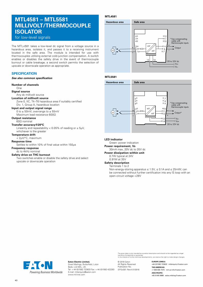
43
© 2018 EatonAll Rights ReservedPublication No.
Eaton Electric Limited, Great Marlings, Butterfield, LutonBeds, LU2 8DL, UK.Tel: + 44 (0)1582 723633 Fax: + 44 (0)1582 422283E-mail: [email protected]
EUROPE (EMEA):
+44 (0)1582 723633 [email protected]
THE AMERICAS:
+1 800 835 7075 [email protected]
ASIA-PACIFIC:
+65 6 645 9888 [email protected]
The given data is only intended as a product description and should not be regarded as a legal warranty of properties or guarantee. In the interest of further technical developments, we reserve the right to make design changes.
MTL4581 – MTL5581MILLIVOLT/THERMOCOUPLE ISOLATORfor low-level signals
The MTLx581 takes a low-level dc signal from a voltage source in a hazardous area, isolates it, and passes it to a receiving instrument located in the safe area. The module is intended for use with thermocouples utilising external cold-junction compensation. A switch enables or disables the safety drive in the event of thermocouple burnout or cable breakage; a second switch permits the selection of upscale or downscale operation as appropriate.
SPECIFICATIONSee also common specification
Number of channelsOne
Signal sourceAny dc millivolt source
Location of millivolt sourceZone 0, IIC, T4–T6 hazardous area if suitably certifiedDiv. 1, Group A, hazardous location
Input and output signal range0 to ± 50mV, overrange to ± 55mVMaximum lead resistance 600Ω
Output resistance60Ω nominal
Transfer accuracy@20°CLinearity and repeatability < 0.05% of reading or ± 5μV,whichever is the greater
Temperature drift< 2μV/°C, maximum
Response timeSettles to within 10% of final value within 150μs
Frequency responsedc to 4kHz nominal
Safety drive on THC burnoutTwo switches enable or disable the safety drive and selectupscale or downscale operation
MTL5581
MTL4581
Hazardous area Safe area
–
+Output
Vs–Vs+
20 to 35V dc
+
–
654
321
mV
mV
987
121110
13 14
mV
* Use compensating cable with thermocouple inputs
Hazardous area Safe area
–
Vs–Vs+
20 to 35V dc
+Output*
+
–
* Use compensating cable with thermocouple inputs
654
321
789
101112
1314
mV
mVmVmV
LED indicatorGreen: power indication
Power requirement, Vs30mA max, 20V dc to 35V dc
Power dissipation within unit0.7W typical at 24V0.91W at 35V
Safety descriptionTerminals 1 to 2Non-energy-storing apparatus ≤ 1.5V, ≤ 0.1A and ≤ 25mW; canbe connected without further certification into any IS loop with anopen-circuit voltage <28V
EPSx581 Rev4 010916
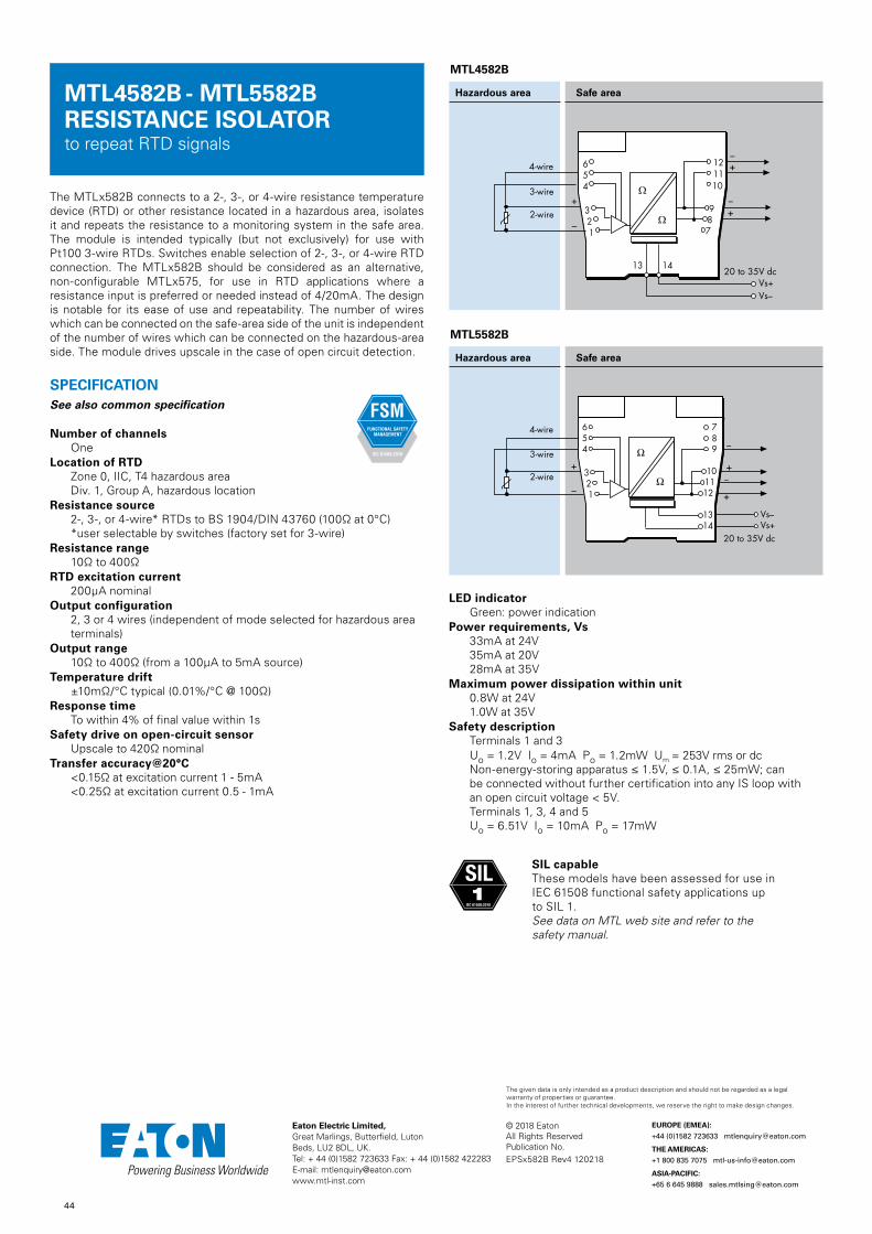
44
© 2018 EatonAll Rights ReservedPublication No.
Eaton Electric Limited, Great Marlings, Butterfield, LutonBeds, LU2 8DL, UK.Tel: + 44 (0)1582 723633 Fax: + 44 (0)1582 422283E-mail: [email protected]
EUROPE (EMEA):
+44 (0)1582 723633 [email protected]
THE AMERICAS:
+1 800 835 7075 [email protected]
ASIA-PACIFIC:
+65 6 645 9888 [email protected]
The given data is only intended as a product description and should not be regarded as a legal warranty of properties or guarantee. In the interest of further technical developments, we reserve the right to make design changes.
MTL4582B - MTL5582BRESISTANCE ISOLATORto repeat RTD signals
The MTLx582B connects to a 2-, 3-, or 4-wire resistance temperature device (RTD) or other resistance located in a hazardous area, isolates it and repeats the resistance to a monitoring system in the safe area. The module is intended typically (but not exclusively) for use with Pt100 3-wire RTDs. Switches enable selection of 2-, 3-, or 4-wire RTD connection. The MTLx582B should be considered as an alternative, non-configurable MTLx575, for use in RTD applications where a resistance input is preferred or needed instead of 4/20mA. The design is notable for its ease of use and repeatability. The number of wires which can be connected on the safe-area side of the unit is independent of the number of wires which can be connected on the hazardous-area side. The module drives upscale in the case of open circuit detection.
SPECIFICATIONSee also common specification
Number of channelsOne
Location of RTDZone 0, IIC, T4 hazardous areaDiv. 1, Group A, hazardous location
Resistance source2-, 3-, or 4-wire* RTDs to BS 1904/DIN 43760 (100Ω at 0°C)*user selectable by switches (factory set for 3-wire)
Resistance range10Ω to 400Ω
RTD excitation current200μA nominal
Output configuration2, 3 or 4 wires (independent of mode selected for hazardous areaterminals)
Output range10Ω to 400Ω (from a 100μA to 5mA source)
Temperature drift±10mΩ/°C typical (0.01%/°C @ 100Ω)
Response timeTo within 4% of final value within 1s
Safety drive on open-circuit sensorUpscale to 420Ω nominal
Transfer accuracy@20°C<0.15Ω at excitation current 1 - 5mA <0.25Ω at excitation current 0.5 - 1mA
LED indicatorGreen: power indication
Power requirements, Vs33mA at 24V35mA at 20V28mA at 35V
Maximum power dissipation within unit0.8W at 24V1.0W at 35V
Safety descriptionTerminals 1 and 3Uo = 1.2V Io = 4mA Po = 1.2mW Um = 253V rms or dcNon-energy-storing apparatus ≤ 1.5V, ≤ 0.1A, ≤ 25mW; canbe connected without further certification into any IS loop withan open circuit voltage < 5V.Terminals 1, 3, 4 and 5Uo = 6.51V Io = 10mA Po = 17mW
MTL4582B
Hazardous area Safe area
–
+
4-wire
3-wire
+
2-wire +
654
321
121110
987
–
–
Vs–Vs+
20 to 35V dc13 14
Ω
Ω
MTL5582B
Hazardous area Safe area
SIL capableThese models have been assessed for use in IEC 61508 functional safety applications up to SIL 1. See data on MTL web site and refer to the safety manual.
SIL1
IEC 61508:2010
EPSx582B Rev4 120218

45
© 2018 EatonAll Rights ReservedPublication No.
Eaton Electric Limited, Great Marlings, Butterfield, LutonBeds, LU2 8DL, UK.Tel: + 44 (0)1582 723633 Fax: + 44 (0)1582 422283E-mail: [email protected]
EUROPE (EMEA):
+44 (0)1582 723633 [email protected]
THE AMERICAS:
+1 800 835 7075 [email protected]
ASIA-PACIFIC:
+65 6 645 9888 [email protected]
The given data is only intended as a product description and should not be regarded as a legal warranty of properties or guarantee. In the interest of further technical developments, we reserve the right to make design changes.
The primary function of the MTLx599, which can be used with all other MTLx500 range of units, is to provide termination and earthing facilities for unused cable cores from hazardous areas.
SPECIFICATIONSee also common specification
Weight60g
MTL4599 - MTL5599DUMMY ISOLATOR
Hazardous area Safe area
Hazardous area Safe area
654
321
121110
987
Unused hazardous-area cores
Unused safe-area cores
Unused safe-area cores
13 14
MTL4599
MTL5599
Safe area
121110
987
13 14
987
121110
The feed–through termination module allows non–IS connections to the MTL4500 backplanes. The wires from the field are connected using screw terminals. Six terminals are provided on top of the module and linked down to the multiway connector on the backplane. The terminals and cables conform to IS regulations so that non–IS and IS signals can be mixed on the same backplane.
Note: Must not be used with signals >50V or >0.25A
SPECIFICATIONSee also common specification
Weight60g
MTL4599N
MTL4599N GENERAL PURPOSE FEED-THROUGH MODULE
EPSx599/N Rev4 010916

46
© 2018 EatonAll Rights ReservedPublication No.
Eaton Electric Limited, Great Marlings, Butterfield, LutonBeds, LU2 8DL, UK.Tel: + 44 (0)1582 723633 Fax: + 44 (0)1582 422283E-mail: [email protected]
EUROPE (EMEA):
+44 (0)1582 723633 [email protected]
THE AMERICAS:
+1 800 835 7075 [email protected]
ASIA-PACIFIC:
+65 6 645 9888 [email protected]
The given data is only intended as a product description and should not be regarded as a legal warranty of properties or guarantee. In the interest of further technical developments, we reserve the right to make design changes.
MTL4500 - MTL5500 RANGE COMMON SPECIFICATIONS
Please go to our website at www.mtl-inst.com for the latest information regarding safety approvals, certificates and entity parameters.
ConnectorsEach unit is supplied with signal connectors, as applicable.When using crimp ferrules for the hazardous or non-hazardous (safe) signal connectors the metal tube length should be 12mm and the wire trim length 14mm.
Isolation250V rms, tested at 1500V rms minimum, between safe- and hazardous-area terminals.MTL4500: 50V between safe-area circuits and power supplyMTL5500: 250V rms between safe-area circuits and power supply
Supply voltage20 – 35V dc
Location of unitsSafe area
TerminalsAccepts conductors of up to 2.5mm2 stranded or single-core
MountingMTL4500 MTL4500 range of backplanesMTL5500 T-section 35mm DIN rail (7.5 or 15mm) to EN 50022
Ambient temperature limits–20 to +60°C (–6 to +140°F) operating–40 to +80°C (–40 to +176°F) storage
Humidity5 to 95% relative humidity
WeightApproximate (except where indicated)
MTL4500 140gMTL5500 150g
EMCTo EN61326 and NE21*
* For 20ms power interruption compliance, a suitable power supply must be used.
HART® is a registered trademark of HART Communication Foundation
DIMENSIONS (MM)
MTL4500
16.0mm PITCH
HAZ
104.8 15.8
121.
8
PW
R
OPB
OPA
OPD
OPC
FLT
Optional TH5000 tag holder for individual isolator identification.Accepts tag label 25 x 12.5 ±0.5mm, 0.2mm thick
MTL5500
EPSx5CS Rev4 010916

47
© 2018 EatonAll Rights ReservedPublication No.
Eaton Electric Limited, Great Marlings, Butterfield, LutonBeds, LU2 8DL, UK.Tel: + 44 (0)1582 723633 Fax: + 44 (0)1582 422283E-mail: [email protected]
EUROPE (EMEA):
+44 (0)1582 723633 [email protected]
THE AMERICAS:
+1 800 835 7075 [email protected]
ASIA-PACIFIC:
+65 6 645 9888 [email protected]
The given data is only intended as a product description and should not be regarded as a legal warranty of properties or guarantee. In the interest of further technical developments, we reserve the right to make design changes.
MPA5500A.C. POWER ADAPTOR
PCS45/PCL45USBCONFIGURATOR FOR MTL CONVERTERS
The MPA5500 enables any MTL5500 module that is normally powered from a nominal 24V DC supply (i.e. those that are not loop-powered) to be powered from a high-voltage AC supply.
It plugs into the power socket (terminals 13 and 14) of an MTL5500 module and clips securely onto the module housing. The 25V DC power output from the adaptor is sufficient to supply a single module and can be connected to any normal AC power source.
Direction ofremoval ofMPA5500
Area requiredfor removal ofMPA5500
11
2015.8
118.
8
133
AC inputs
Top of DIN rail
SPECIFICATIONInput voltage
85 – 265V AC, (45–65Hz)Efficiency
71% typ. at 230V ACPower dissipation
1.2W typ at 230V AC.Input terminals
Cage-clamp terminals accommodating conductors upto 1.5mm2 stranded or 16AWG single-core
Input protectioninternal fuse, not user serviceable
Output voltage25Vdc ± 10%
Output current120mA at 25V
Ambient temperatureOperating: –20 to +60°CStorage: –40 to +80°C
MountingPlugs into and clips onto MTL5500 range I/O moduleIt is not for use with any equipment other than MTL5500.
Humidity5 to 95% relative humidity
MechanicalIngress Protection: IP20Material: polycarbonateWeight: 28g approx.
Standards complianceEN 61326, EN 61010
SPECIFICATIONPCL45USB hardwareLocation
Safe areaConnections
PC side: USB B(F) socketConverter side: cable with 3.5mm jackplug, 3-pole for MTL4500 and MTL5500 range of converters. An adapter cable is provided for other earlier MTL converters.
Cable lengthsConverter side (fitted): 1.5mUSB cable A(M) to B(M) (supplied): 2m
Ambient temperature limits–10°C to +60°C operating–20°C to +70°C storage
Humidity5 to 95% relative humidity (non-condensing)
Weight200g
PCS45 Configuration softwareCompatible with Windows XP, Win7, Win8.Consult MTL for operation with any other operating system.
Software mediumPCS45 supplied on CDUpdates are available at www.mtl-inst.com
Recommended minimum PC configurationMicrosoft Windows XP, Win7, Win820MB of available hard disc spaceCD ROM driveAvailable USB port Printer (local or network)
Safe area
The PCS45/PCL45USB configurator allows MTL converters to be configured from a standard PC running a Microsoft® Windows® operating system. It comprises PC software, provided on a CD (PCS45), and an ATEX certified interfacing link (PCL45USB). Converters can be configured from the safe area, while on-line, and configurations can be saved to disk and printed out when required. It is suitable for use with MTL4000, MTL4500, MTL5000 and MTL5500 range of products.
EPS45/5500 Rev5 010916

48
© 2018 EatonAll Rights ReservedPublication No.
Eaton Electric Limited, Great Marlings, Butterfield, LutonBeds, LU2 8DL, UK.Tel: + 44 (0)1582 723633 Fax: + 44 (0)1582 422283E-mail: [email protected]
EUROPE (EMEA):
+44 (0)1582 723633 [email protected]
THE AMERICAS:
+1 800 835 7075 [email protected]
ASIA-PACIFIC:
+65 6 645 9888 [email protected]
The given data is only intended as a product description and should not be regarded as a legal warranty of properties or guarantee. In the interest of further technical developments, we reserve the right to make design changes.
PSG60E24RM 24V 2.5A PSU24Vdc Power supply, DIN rail mounting,mains input.
MTL5500 RANGE POWERBUS KITSPB - 8T,16T,24T,32T
SPECIFICATION See also common specification AC input range 85Vac to 264Vac, 47 to 63Hz DC input range 120Vdc to 375Vdc DC output 24V (adjustable 24-28V) Output current
2.5A (3,75A for 5s)Main interruption holdup time >20msEfficiency
90%Input to Output isolation 4kVacIsolation Input/output to ground 1.5kVacHousing material AluminiumDimensions L x W x H 121 x 32 x 125mmWeight 370gWire size 0.3 to 3.3mm2, AWG 22-12 with removable terminalsOperating Temperature -20°C to +80°CStorage Temperature -25°C to +85°C
A quick and easy way to distribute DC power to MTL5500 range modules. Each powerbus kit includes 4 single ferrules, 4 twin ferrules and 2 insulation displacement connectors (Scotchlok).
SPECIFICATIONAvailable in 4 different lengths:
PB - 8T = 8 connectors and loopsPB - 16T = 16 connectors and loopsPB - 24T = 24 connectors and loopsPB - 32T = 32 connectors and loops
Insulation material :PVC
Conductor :24 strands of 0.2mm dia (0.75mm2) standard copper
Insulation thickness :0.5 to 0.8 mm
Current rating : 12A max
Operating temperature range :–20ºC to +60ºC
Max voltage drop on 32 modules drawing 130mA max : 0.5V
– +
Optional insulationdisplacementconnectors
x2
CHOOSING A POWERBUS KITChoose a powerbus where the number of power plugs is greater than or equal to the number of isolators to be powered and if necessary cut the powerbus to the required number of terminations.
Note: To reduce the risk of excessive voltage drop or overcurrent do not connect powerbuses in series.
A general purpose 24V dc power supply for use with MTL isolator and barrier product ranges. Single 24V output with adjustable voltage and status indication.
For mounting on 35mm top hat DIN rail.(replacement for MTL5991)
Terminals Function
L Mains input line
N Mains input neutral
E Earth
+ 24V dc+
- 24Vdc
EPS PSG60E24RM/ MTL5500 Rev5 160418

49
© 2018 EatonAll Rights ReservedPublication No.
Eaton Electric Limited, Great Marlings, Butterfield, LutonBeds, LU2 8DL, UK.Tel: + 44 (0)1582 723633 Fax: + 44 (0)1582 422283E-mail: [email protected]
EUROPE (EMEA):
+44 (0)1582 723633 [email protected]
THE AMERICAS:
+1 800 835 7075 [email protected]
ASIA-PACIFIC:
+65 6 645 9888 [email protected]
The given data is only intended as a product description and should not be regarded as a legal warranty of properties or guarantee. In the interest of further technical developments, we reserve the right to make design changes.
MTL5500 RANGEENCLOSURES
SPECIFICATIONConstruction
Glass reinforced polycarbonate base - DX070Glass reinforced polyester base - DX170Transparent polycarbonate lid
ProtectionDust-tight and water-jet proof to IEC529:IP65
Lid fixingCaptive fixing screws
Weight (excluding barriers/isolators) kgDX070 0.8DX170 2.6
Items providedDIN rail - fittedETL7000 Earth terminals (2 x) - fitted"Take care IS" front adhesive labelCable trunking (DX170 only)
Note: Isolators are not included.
MountingWall fixing lugs provided. For further details refer to INM5500.
Tagging and earth railAccommodates MTL5500 range of accessories.
Permitted locationSafe (non-hazardous) area
DIMENSIONS (mm) AND MOUNTING
Note: N. America/Canada - Enclosures are rated NEMA 4X so can be used in Class 1, Division 2 (gases) location, but check with local requirements and ensure all cable entries also conform. Additional warning label will be required on or near the enclosure, see installation details. Not suitable for Class II or III, Division 2 hazardous locations.
Approximate capacities (on DIN rail between earth terminals)
Number of MTL5500 isolators
DX070 4 (2)*
DX170 10 (8)*
* Use these figures when IMB57 mounting blocks for tagging/earth are included.
Ambient temperature limitsDependent on units fitted. See instruction manual INM5500.
130
180
153.5113.5
163.
5
203.
5
Ø 5.2
70
EPS45/5500 Rev6 040517

50
© 2018 EatonAll Rights ReservedPublication No.
Eaton Electric Limited, Great Marlings, Butterfield, LutonBeds, LU2 8DL, UK.Tel: + 44 (0)1582 723633 Fax: + 44 (0)1582 422283E-mail: [email protected]
EUROPE (EMEA):
+44 (0)1582 723633 [email protected]
THE AMERICAS:
+1 800 835 7075 [email protected]
ASIA-PACIFIC:
+65 6 645 9888 [email protected]
The given data is only intended as a product description and should not be regarded as a legal warranty of properties or guarantee. In the interest of further technical developments, we reserve the right to make design changes.
MTL5500 RANGEACCESSORIES
MTL5500 range of isolators mount quickly and easily onto standard DIN rail. A comprehensive range of accessories simplifies earthing and tagging arrangements.
See also‘MTL5500 range of powerbus kits'
MOUNTINGTHR2 DIN rail,1m length
DIN rail to EN50022; BS5584; DIN46277
MS010 DIN rail module spacer, 10mm, pack of 5Grey spacer, one required between each MTL5533 or MTL5995-PS and any adjacent module on a DIN rail, to provide 10mm air-circulation space between modules
EARTH RAILS AND TAG STRIPIMB57 Insulating mounting block
One required at each end of a tagging strip/earth rail. Suitable for low-profile (7.5mm) and high-profile (15mm) symmetrical DIN rail.
ETM7 Earth terminal, bag of 50For terminating cable screens and 0V returns on the ERL7 earth rail. For cables ≤ 4mm2. Exact dimension dependent on manufacturer.
TAG57 Tagging strip, 1m lengthCut to size. Supplied with tagging strip label suitable for MTL5000 or MTL5500 modules.
TGL57 Tagging strip labels, set of 10 x 0.5mSpares replacement, for use with TAG57 tagging strip. Suitable for MTL5000 or MTL5500 modules.
INDIVIDUAL ISOLATOR IDENTIFICATIONTH5000 tag holders
Each isolator may be fitted with a clear plastic tag holder, as shown below. Order TH5000, pack of 20.
CONNECTORSEach MTL5500 unit is supplied with signal and power connectors, as applicable.
Spares replacement connectors are available separately; see ordering information.
ERB57S Earth-rail bracket, straight Nickel-plated; supplied with two push fasteners, one (14mm, 35mm2) earth-rail clamp and one (10mm, 16mm2) earth clamp.
ERL7 Earth rail, 1m lengthNickel-plated; may be cut to length.
EPS45/5500 Rev4 010916
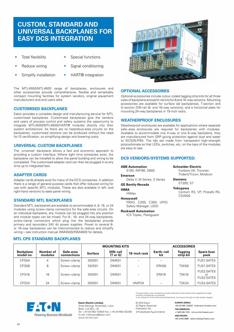
51
© 2018 EatonAll Rights ReservedPublication No.
Eaton Electric Limited, Great Marlings, Butterfield, LutonBeds, LU2 8DL, UK.Tel: + 44 (0)1582 723633 Fax: + 44 (0)1582 422283E-mail: [email protected]
EUROPE (EMEA):
+44 (0)1582 723633 [email protected]
THE AMERICAS:
+1 800 835 7075 [email protected]
ASIA-PACIFIC:
+65 6 645 9888 [email protected]
The given data is only intended as a product description and should not be regarded as a legal warranty of properties or guarantee. In the interest of further technical developments, we reserve the right to make design changes.
• Total flexibility • Special functions
• Reduce wiring • Signal conditioning
• Simplify installation • HART® integration
ABB AutomationS100, INFI90, S800
EmersonDelta V, M Series, S Series
GE Bently-Nevada
HIMAHIMax
HoneywellPMIO, C200, C300, UPIO, Safety Manager, USIO
Rockwell AutomationICS Triplex, Plantguard
Schneider ElectricFoxboro I/A, Triconex Trident/Tricon, Modicon
SiemensET200, S7
YokogawaCentum R3, VP, Prosafe RS, CS3000
The MTL4500/MTL4600 range of backplanes, enclosures and other accessories provide comprehensive, flexible and remarkably compact mounting facilities for system vendors, original equipment manufacturers and end users alike.
CUSTOMISED BACKPLANESEaton provides a complete design and manufacturing service for MTL customised backplanes. Customised backplanes give the vendors and users of process control and safety systems the opportunity to integrate MTL4500/MTL4600/HART® modules directly into their system architecture. As there are no hazardous-area circuits on the backplanes, customised versions can be produced without the need for IS certification, so simplifying design and lowering costs.
UNIVERSAL CUSTOM BACKPLANESThe 'universal' backplane allows a fast and economic approach to providing a custom interface. Where tight time schedules exist, the backplane can be installed to allow the panel building and wiring to be completed. The customised adapter card can then be plugged in at any time up to integrated test.
ADAPTER CARDSAdapter cards already exist for many of the DCS companies. In addition there is a range of general purpose cards that offer reduced wiring for use with specific MTL modules. These are also available in left- and right-hand versions to ease panel wiring.
STANDARD MTL BACKPLANESStandard MTL backplanes are available to accommodate 4, 8, 16, or 24 modules using screw-clamp connectors for the safe-area circuits. On an individual backplane, any module can be plugged into any position and module types can be mixed. For 8-, 16- and 24-way backplanes, screw-clamp connectors which plug into the backplanes provide primary and secondary 24V dc power supplies. Power to several 8- or 16-way backplanes can be interconnected to reduce and simplify wiring – see instruction manual INM4500/INM4600 for details.
OPTIONAL ACCESSORIESOptional accessories include colour coded tagging strip kits for all three sizes of backplane and earth rail kits for 8 and 16-way versions. Mounting accessories are available for surface (all backplanes), T-section and G-section DIN-rail (8- and 16-way versions), and a horizontal plate for mounting 24-way backplanes in 19-inch racks.
WEATHERPROOF ENCLOSURESWeatherproof enclosures are available for applications where separate safe–area enclosures are required for backplanes with modules. Available to accommodate one 4-way or one 8-way backplane, they are manufactured from GRP giving protection against dust and water to IEC529:IP65. The lids are made from transparent high-strength polycarbonate so that LEDs, switches, etc, on the tops of the modules are easy to see.
MOUNTING KITS ACCESSORIES
Backplane model no.
Number of modules
Safe-area connections Surface DIN–rail
(T or G) 19–inch rack Earth–rail kit
Tagging strip kit
Spare fuse pack
CPS04 4 Screw–clamp SMS01 DMK01 – – FUS1.0ATE5
CPS08 8 Screw–clamp SMS01 DMK01 – ERK08 TSK08 FUS1.0ATE5
CPS16 16 Screw–clamp SMS01 DMK01 – ERK16 TSK16FUS2.0ATE5
or FUS2.5ATE5
CPS24 24 Screw–clamp SMS01 DMK01 HMP24 – TSK24 FUS4.0ATE5
MTL CPS STANDARD BACKPLANES
CUSTOM, STANDARD AND UNIVERSAL BACKPLANES FOR EASY DCS INTEGRATION
DCS VENDORS/SYSTEMS SUPPORTED:
EPS45/5500 Rev6 010916

52
© 2018 EatonAll Rights ReservedPublication No.
Eaton Electric Limited, Great Marlings, Butterfield, LutonBeds, LU2 8DL, UK.Tel: + 44 (0)1582 723633 Fax: + 44 (0)1582 422283E-mail: [email protected]
EUROPE (EMEA):
+44 (0)1582 723633 [email protected]
THE AMERICAS:
+1 800 835 7075 [email protected]
ASIA-PACIFIC:
+65 6 645 9888 [email protected]
The given data is only intended as a product description and should not be regarded as a legal warranty of properties or guarantee. In the interest of further technical developments, we reserve the right to make design changes.
CPS BACKPLANE DIMENSIONS (mm)
Power requirements, Vs21V dc to 35V dc through plug-in connectors
Safe–area connectionsCPS: 2.5mm2 screw-clamp terminals – 6 positions per module
Weight (without modules or accessories)
CPS04: 96gCPS08: 225gCPS16: 419gCPS24: 592g
BACKPLANE ACCESSORIES
CPS04 CPS04-CC
CPS08 CPS08-CC
CPS16 CPS16-CC
CPS24
SCK45 - backplane clips
10 x strip of four
16 x strip of two
MCK45 - backplane clips
HMP24 - 19" RACK MOUNTING PLATE FOR CPS24
-CC - Conformal Coating
EPS45/5500 Rev6 010916

53
© 2018 EatonAll Rights ReservedPublication No.
Eaton Electric Limited, Great Marlings, Butterfield, LutonBeds, LU2 8DL, UK.Tel: + 44 (0)1582 723633 Fax: + 44 (0)1582 422283E-mail: [email protected]
EUROPE (EMEA):
+44 (0)1582 723633 [email protected]
THE AMERICAS:
+1 800 835 7075 [email protected]
ASIA-PACIFIC:
+65 6 645 9888 [email protected]
The given data is only intended as a product description and should not be regarded as a legal warranty of properties or guarantee. In the interest of further technical developments, we reserve the right to make design changes.
MTL4500 range of backplanes can be customised for specific applications and customer’s requirements. All the signals on the backplane are ‘safe-area’ so custom designs are possible without the need for certification. Eaton offers a fast and efficient customising service upon request.
Many installations can benefit from the use of existing custom solutions. These provide reduced system wiring, modularisation of the channels to match the IO card. In addition diagnostics, such and line fault detection, can be grouped prior to connection into the system.
Remote cable connections:
In addition to the many DCS solutions, listed on a previous page, are backplanes and cables that are ideal when the isolators are mounted in remote cabinets and the signals need to be returned to the system via a multicore cable.
CP-DYN RANGE
CUSTOM BACKPLANES
FTA Size Function MTL modules
CP-DYNB-AIO B 16ch analogue input /output MTL4541, 4546Y, 4573
CP-DYNB-AI250 B 16ch analogue input 1-5V o/p MTL4541, 4573
CP-DYNA-2AIO A 16ch analogue input / output MTL4544, 4549Y
CP-DYNB-DI B 16ch digital input MTL4511, 4514
CP-DYNB-DILF B 16ch digital input with LFD MTL4514
CP-DYNB-2DI B 32ch digital input MTL4513, 4516, 4517
CP-DYNB-4DI B 48ch digital input MTL4510
CP-DYNA-DO A 8ch digital output MTL4521, 4521L
CP-DYNB-DO B 16ch digital output MTL4521, MTL4521L
CABLES
All FTAs use the Tyco 20 pin Dynamic range of connectors. Cables are fitted with a mating connector and free ends the other, for connection to the system card.
Cable ordering code
CABDYN20-0.5 0.5m cable CABDYN20-1 1.0m CABDYN20-2 2.0m CABDYN20-3 3.0m CABDYN20-5 5.0m CABDYN20-8 8.0m CABDYN20-10 10m CABDYN20-15 15m CABDYN20-20 20m CABDYN20-25 25m CABDYN20-30 30m
DESCRIPTION
For use when the IS interfaces are remotely mounted from the control system, this series of cable connected FTAs provide a simple plug/socket connection method for IS field devices to any control system. The FTAs come fitted with mounting pillars for surface mounting or may be used with the DIN rail mounting kit to mount on a single DIN rail.
The cable connections between the system card and the FTA use the Tyco Dynamic range of connector which provide a reliable and high density solution.
EPS45/5500 Rev6 010916
CP-DYN DIMENSIONS
For full technical details please contact you local Eaton sales office.

54
© 2018 EatonAll Rights ReservedPublication No.
Eaton Electric Limited, Great Marlings, Butterfield, LutonBeds, LU2 8DL, UK.Tel: + 44 (0)1582 723633 Fax: + 44 (0)1582 422283E-mail: [email protected]
EUROPE (EMEA):
+44 (0)1582 723633 [email protected]
THE AMERICAS:
+1 800 835 7075 [email protected]
ASIA-PACIFIC:
+65 6 645 9888 [email protected]
The given data is only intended as a product description and should not be regarded as a legal warranty of properties or guarantee. In the interest of further technical developments, we reserve the right to make design changes.
ANALOGUE SIGNAL REPEAT
CPS04-AIREP backplane may be used to generate a repeat output from a single transmitter source. This includes high integrity loops in general purpose applications. The MTL4641 is used to generate an isolated repeat signal from an existing 4-20mA loop.
CPS04-2AIO, 8 channel backplane, is used with IS signals with 2 channel AI or AO modules or with the MTL4544D to generate 4 inputs with repeat outputs.
MTL CUSTOM BACKPLANE SOLUTIONS
A wide range of backplanes can be offered with application specific functions. System connection options and modularity for individual signal types can be provided to offer significant space and cost savings. Please contact your local Eaton sales office if you wish to discuss your application requirements.
PRODUCT MIGRATION
Migration options for legacy MTL4000 range installations are also available. This enables isolators to be easily upgraded, or re-connecting existing isolators to a new control system, with the minimum of disturbance to existing wiring. For more information on product migration visit the resource section at www.mtl-inst.com
CPELCO RANGE
A range of dedicated backplanes to interface with MTL4500 range of intrinsically safe isolator modules and the MTL HART maintenance system products. The backplanes offer a standard Elco interface connector for use in systems where the IS interfaces are remote from the DCS.
Backplane Function MTL module Cable
CPM08-2AIO 16ch AI 4-20mA MTL4544/4576/4549Y x 8 Elco38 x 1
CPM08-2AV 16ch AI 1-5V MTL4544/4576 x 8 Elco38 x 1
CPM16-AIO 16ch AIO 4-20mA MTL4541/4573/4546Y Elco38 x 1
CPM16-2AIO 32ch AI 4-20mA MTL4544/4576/4549Y x 16 Elco38 x 2
CPM16-2AV 32ch AI 1-5V MTL4544/4576 x 16 Elco38 x 2
CPM08-DDI 16ch DI MTL4513/4516 Elco38 x 1
CPM16-DO 16ch DO MTL4524/4523R Elco38 x 1
CGM08-DO 8ch DO MTL4521/4521L (loop powered) Elco38 x 1
For full technical details please contact your local MTL sales office.
EPS45/5500 Rev6 010916

55
© 2018 EatonAll Rights ReservedPublication No.
Eaton Electric Limited, Great Marlings, Butterfield, LutonBeds, LU2 8DL, UK.Tel: + 44 (0)1582 723633 Fax: + 44 (0)1582 422283E-mail: [email protected]
EUROPE (EMEA):
+44 (0)1582 723633 [email protected]
THE AMERICAS:
+1 800 835 7075 [email protected]
ASIA-PACIFIC:
+65 6 645 9888 [email protected]
MTL4500/5500 range isolatorsSpecify part number: eg, MTL4511, MTL5575
Individual isolator identificationTH5000 Tag holder (Pack of 20)
Connectors - MTL4500 & MTL5500HAZ1-3 Hazardous-area plug,
terminals 1, 2 and 3
HAZ4-6 Hazardous-area plug, terminals 4, 5 and 6
HAZ-CJC Hazardous-area plug, terminals 1 and 3 with cold-junction sensor
HAZ-CJC2 Hazardous-area plug, terminals 4 and 6 with cold-junction sensor
SAF1-3 Safe-area plug, terminals 1, 2 and 3
SAF4-6 Safe-area plug, terminals 4, 5 and 6
Connectors - MTL5500 onlySAF7-9 Safe-area plug, terminals 7, 8 and 9
SAF10-12 Safe-area plug, terminals 10, 11 and 12
PWR5000 Power connector, terminals 13 and 14
PowerBus - MTL5500 onlyPB-8T Powerbus Kit for up to 8 isolators
PB-16T Powerbus Kit for up to 16 isolators
PB-24T Powerbus Kit for up to 24 isolators
PB-32T Powerbus Kit for up to 32 isolators
MTL5500 mounting accessoriesTHR2 1m length of DIN rail to EN 50022;
BS 5584; DIN 46277
MS010 DIN-rail module spacer, 10mm (pack of 5)
MTL5500 earth-rail and tag strip accessoriesIMB57 Insulating mounting block
ERB57S Earth-rail bracket, straight
ERL7 Earth-rail, 1m length
ETM7 Earth terminal, bag of 50
TAG57 Tagging strip, 1m length
TGL57 Tagging strip labels, set of 10 x 0.5m
MTL5500 enclosuresDX070 Enclosure for MTL5500 x 4
DX170 Enclosure for MTL5500 x 10
MTL4500 standard backplanesCPS04 4-way backplane screw-clamp connector
CPS08 8-way backplane screw-clamp connector
CPS16 16-way backplane screw-clamp connector
CPS24 24-way backplane screw-clamp connector
MTL4500 custom backplanesContact your local Eaton sales office for options and advice
MTL4500 backplane mounting accessoriesDMK01 DIN-rail mounting kit, T- or G-section
(pack of 40) 8-way backplanes require 4, 16-way backplanes require 6
SMS01 Surface mounting kit (pack of 40) 4- and 8-way backplanes require 4, 16-way backplanes require 6, 24-way backplanes require 8
HMP24 Horizontal mounting plate and screws for 19-inch rack mounting
24-way backplanes only
BMK08 Mounting kit for one 4- or 8-way backplane
BMK16 Mounting kit for one 16-way backplane
MTL4500 backplane accessoriesERK08 Earth rail kit for CPS08 backplane
ERK16 Earth rail kit for CPS16 backplane
TSK08 Tagging strip kit for CPS08 backplane
TSK16 Tagging strip kit for CPS16 backplane
TSK24 Tagging strip kit for CPS24 backplane
FUS1.0ATE5 Fuse kit, 1.0A (pack of 10)
FUS2.0ATE5 Fuse kit, 2.0A (pack of 10)
FUS2.5ATE5 Fuse kit, 2.5A (pack of 10)
FUS4.0ATE5 Fuse kit, 4.0A (pack of 10)
MCK45 MTL4000 backplane conversion kit (16 clip pairs per pack)
SCK45 Module 4-clip strips (10 strips + 40 rivets per pack)
MPL01 Module position label (blank) (50 per pack)
MCC45 Module backplane connector cover (pack of 50)
LiteratureINM5500 MTL5500 range instruction manual
INM4500/ MTL4500/MTL4600 range instruction manual4600
Configurator and softwarePCL45USB Configurator, PC interface and software
PCS45 PC software
ORDERING INFORMATION
Please go to our website at www.mtl-inst.com for the latest information regarding safety approvals, certificates and entity parameters.
EPS45/5500 Rev6 010916