MTi User Manual - sensores-de-medida.es · [email protected] [email protected] MTi 10 Document MT0605P,...
76
[email protected] [email protected] Document MT0605P, Revision B, 18 Dec 2012 MTi 10-series and MTi 100-series MTi User Manual
Transcript of MTi User Manual - sensores-de-medida.es · [email protected] [email protected] MTi 10 Document MT0605P,...

[email protected] [email protected]
Document MT0605P, Revision B, 18 Dec 2012
MTi 10-series and MTi 100-series
MTi User Manual

Document MT0605P.B © Xsens MTi User Manual
ii
Revisions
Revision Date By Changes
A 26 Sep 2012 MHA Initial release
B 18 Dec 2012 MHA Included MTi-G-700
© 2012, Xsens Technologies B.V. All rights reserved. Information in this document is subject to change without notice. Xsens is a registered trademark of Xsens Technologies B.V. MTi, MTx, MTi-G and MVN are trademarks of Xsens Technologies B.V.

Document MT0605P.B © Xsens MTi User Manual
iii
Table of Contents 1 REFERENCES ............................................................................................................................................ 2
2 INTRODUCTION ....................................................................................................................................... 3
2.1 MTI 10-SERIES ................................................................................................................................. 4 2.1.1 MTi-30 AHRS .................................................................................................................................... 4 2.1.2 MTi-20 VRU ...................................................................................................................................... 4 2.1.3 MTi-10 IMU ...................................................................................................................................... 4
2.2 MTI 100-SERIES ............................................................................................................................... 5 2.2.1 MTi-G-700 GPS/INS .......................................................................................................................... 5 2.2.2 MTi-300 AHRS .................................................................................................................................. 5 2.2.3 MTi-200 VRU .................................................................................................................................... 5 2.2.4 MTi-100 IMU .................................................................................................................................... 5 2.2.5 Identifying device functionality using the unique Device Identifier .................................................. 6
2.3 EVOLUTION OF MTI PRODUCTS ............................................................................................................ 7 2.4 OVERVIEW MTI DEVELOPMENT KIT ...................................................................................................... 8
2.4.1 Contents ........................................................................................................................................... 8 2.5 INSTALLATION ................................................................................................................................... 9
2.5.1 Transient accelerations .................................................................................................................... 9 2.5.2 Vibrations ......................................................................................................................................... 9 2.5.3 Magnetic materials and magnets .................................................................................................... 9
2.6 TYPICAL USER SCENARIOS .................................................................................................................. 11 2.6.1 MT Software Suite .......................................................................................................................... 11 2.6.2 Getting Started with the MT Manager ........................................................................................... 12 2.6.3 Using the Software Development Kit (SDK) .................................................................................... 13 2.6.4 Direct low-level communication with MTi ...................................................................................... 15 2.6.5 Migration from MT SDK 3.3 (CMT) ................................................................................................. 15 2.6.6 Terms of use MT Software Suite ..................................................................................................... 16
3 MTI SYSTEM OVERVIEW ........................................................................................................................ 17
3.1 CALIBRATION .................................................................................................................................. 17 3.2 XSENS KALMAN FILTER (XKF3I) FOR MTI 10-SERIES .............................................................................. 17
3.2.1 Using the acceleration of gravity to stabilize inclination (roll/pitch) ............................................. 17 3.2.2 Using the Earth magnetic field to stabilize yaw ............................................................................. 18 3.2.3 Initialization .................................................................................................................................... 18 3.2.4 XKF3i filter profiles ......................................................................................................................... 18
3.3 XSENS SENSOR FUSION ALGORITHM FOR MTI 100-SERIES ........................................................................ 20 3.3.1 MTi 100-series filter........................................................................................................................ 20 3.3.2 Transient accelerations .................................................................................................................. 20 3.3.3 Magnetic distortions ...................................................................................................................... 20 3.3.4 Loss of GPS ..................................................................................................................................... 20 3.3.5 MTi 100-series filter profiles ........................................................................................................... 20 3.3.6 MTi-G-700 filter profiles ................................................................................................................. 21
4 OUTPUT SPECIFICATION ........................................................................................................................ 23
4.1 OVERVIEW OF DATA OUTPUTS ............................................................................................................ 24 4.2 COORDINATE SYSTEMS ...................................................................................................................... 25
4.2.1 Calibrated inertial data and magnetic field data ........................................................................... 25 4.2.2 Delta_angle and delta_velocity ...................................................................................................... 25 4.2.3 Orientation data ............................................................................................................................. 26

Document MT0605P.B © Xsens MTi User Manual
iv
4.2.4 Velocity data .................................................................................................................................. 27 4.2.5 Position data .................................................................................................................................. 27
4.3 ORIENTATION PERFORMANCE SPECIFICATION ......................................................................................... 30 4.4 POSITION AND VELOCITY PERFORMANCE SPECIFICATION (MTI-G-700) ...................................................... 31 4.5 ORIENTATION OUTPUT MODES ........................................................................................................... 32
4.5.1 Quaternion orientation output mode ............................................................................................. 32 4.5.2 Euler angles orientation output mode............................................................................................ 33 4.5.3 Rotation Matrix orientation output mode ..................................................................................... 34
4.6 SENSOR DATA PERFORMANCE SPECIFICATION ......................................................................................... 35 4.6.1 Gyroscopes ..................................................................................................................................... 35 4.6.2 Accelerometers and magnetometer ............................................................................................... 35 4.6.3 Barometer ...................................................................................................................................... 36 4.6.4 GPS receiver .................................................................................................................................... 36
4.7 BUILT-IN SELF-TEST .......................................................................................................................... 37 4.8 TEST AND CALIBRATION CERTIFICATE ................................................................................................... 38 4.9 SENSORS DATA OUTPUTS ................................................................................................................... 39
4.9.1 Physical sensor model .................................................................................................................... 39 4.9.2 Calibrated delta_q and delta_v outputs ......................................................................................... 40 4.9.3 Calibrated inertial and magnetic data outputs .............................................................................. 40 4.9.4 Free acceleration ............................................................................................................................ 40 4.9.5 Uncalibrated raw output mode ...................................................................................................... 41
4.10 LEGACY OUTPUT MESSAGES ............................................................................................................... 42 4.11 RESET OF OUTPUT OR REFERENCE CO-ORDINATE SYSTEMS ........................................................................ 43 4.12 TIMESTAMP AND PACKET COUNTER OUTPUT .......................................................................................... 46
4.12.1 Packet counter ................................................................................................................................ 46 4.12.2 Time UTC ........................................................................................................................................ 46 4.12.3 Time stamp (Sample Time Fine) ..................................................................................................... 46
4.13 STATUS BYTE ................................................................................................................................... 47
5 BASIC COMMUNICATION ...................................................................................................................... 48
5.1 INTRODUCTION ............................................................................................................................... 48 5.2 STATES .......................................................................................................................................... 48 5.3 MESSAGES ..................................................................................................................................... 49
5.3.1 Message structure .......................................................................................................................... 49 5.3.2 Message usage ............................................................................................................................... 49 5.3.3 Common messages ......................................................................................................................... 51
5.4 COMMUNICATION TIMING................................................................................................................. 53 5.5 TRIGGERING AND SYNCHRONIZATION ................................................................................................... 55
5.5.1 External device triggers MTi (Send Latest) ..................................................................................... 55 5.5.2 Marker in MT data (Trigger Indication) .......................................................................................... 55 5.5.3 MTi triggers external devices (Interval Transition Measurement) ................................................. 56 5.5.4 Clock synchronization (Clock Bias Estimation) ............................................................................... 56 5.5.5 Combining synchronization functions ............................................................................................ 57
5.6 INTERNAL CLOCK ACCURACY ............................................................................................................... 58 5.6.1 Clock of MTi’s without GPS receiver ............................................................................................... 58 5.6.2 Clock of MTi-G-700 GPS/INS ........................................................................................................... 58
5.7 DEFAULT SERIAL CONNECTION SETTINGS .............................................................................................. 59 5.7.1 General definitions for binary data ................................................................................................ 59 5.7.2 Serial or USB communication ......................................................................................................... 59
6 PHYSICAL SPECIFICATIONS .................................................................................................................... 60

Document MT0605P.B © Xsens MTi User Manual
v
6.1 PHYSICAL PROPERTIES OVERVIEW ........................................................................................................ 60 6.2 POWER SUPPLY ............................................................................................................................... 60 6.3 MECHANICAL AND ELECTRICAL INTERFACE SPECIFICATIONS ....................................................................... 61
6.3.1 Encased MTi connectors overview ................................................................................................. 61 6.3.2 OEM connections overview ............................................................................................................ 63 6.3.3 Additional interface specifications ................................................................................................. 64
6.4 HOUSING MECHANICAL SPECIFICATIONS ............................................................................................... 65 6.4.1 Environmental protection of the housing ....................................................................................... 65 6.4.2 Dimensions MTi .............................................................................................................................. 65 6.4.3 MTi 10-series technical drawing..................................................................................................... 66 6.4.4 MTi 100-200-300 technical drawing .............................................................................................. 67 6.4.5 MTi-700-G technical drawing ......................................................................................................... 68
7 IMPORTANT NOTICES ............................................................................................................................ 69
7.1 SAFETY INSTRUCTIONS ...................................................................................................................... 69 7.2 ABSOLUTE MAXIMUM RATINGS ........................................................................................................... 69 7.3 MAINTENANCE ................................................................................................................................ 69 7.4 CE DECLARATION OF CONFORMITY FOR THE MT DEVICES ...................................................................... 70 7.5 FCC DECLARATION OF CONFORMITY FOR THE MT DEVICES ...................................................................... 71 7.6 WARRANTY AND LIABILITY ................................................................................................................. 72 7.7 CUSTOMER SUPPORT ........................................................................................................................ 72

Document MT0605P.B © Xsens MTi User Manual
2
1 References
Reference id Document description
[LLCP] “MT Low-Level Communication Protocol Documentation.pdf”, document ID MT0101P
[SDK] “MT Software Development Kit Documentation.pdf”, document ID MT0200P
[MTM] “MT Manager User Manual.pdf”, document ID MT0216P
[XDA_DOC] XDA doxygen HTML documentation. Found in Xsens folder structure
[MTI_TD] “MTi Technical Datasheet.pdf”, document ID MT0503P

Document MT0605P.B © Xsens MTi User Manual
3
2 Introduction The MTi product portfolio from Xsens currently has 7 family members ranging in functionality from inertial measurement units (IMU’s) to a fully integrated GPS/INS solution. All products contain a 3D inertial sensor assembly (ISA: gyroscopes and accelerometers) and 3D magnetometers, with optionally a barometer and GNSS receiver. The MTi product range is divided in two series, the MTi 10-series and the MTi 100-series. The MTi 10-series is Xsens’ entry level model with robust accuracy and a limited range of IO options. The 100-series is a revolutionary new class of MEMS IMU’s, orientation and position sensor modules offering unprecedented accuracies and a wide array of IO interfaces. All MTi’s have a powerful multi-processor core design, capable of processing roll, pitch and yaw with extremely low latencies, as well as outputting calibrated 3D linear acceleration, rate of turn (gyro), (earth) magnetic field and atmospheric pressure (100-series only) data. The MTi-G-700 GPS/INS also offers 3D position and 3D velocity. Over 50 various output formats can be provided directly from the MTi interface. The various outputs per product can be found in section 4.1. This documentation describes the use, basic communication interfaces and specifications of all the 7 MTi’s. Where they differ is clearly indicated. All products are designed to be interchangeable from a mechanical and software interface point of view.

Document MT0605P.B © Xsens MTi User Manual
4
2.1 MTi 10-series
The MTi 10-series is the basic product range of the MTi product portfolio, offering inertial data and orientation data at an affordable price. The MTi 10-series consists of 3 products that have various integration levels. The MTi-10 series can easily be recognized by the silver base plate. There are no visual differences between the MTi-10 IMU, MTi-20 VRU and MTi-30 AHRS, other than the label.
2.1.1 MTi-30 AHRS
The MTi-30 AHRS is a full gyro-enhanced Attitude and Heading Reference System (AHRS). It outputs drift-free roll, pitch and true/magnetic North referenced yaw, plus sensors data: 3D acceleration, 3D rate of turn and 3D earth-magnetic field data. All products of the MTi 10-series are also capable of outputting data generated by the Strapdown integration algorithm (orientation and velocity increments ∆q and ∆v).
2.1.2 MTi-20 VRU
The MTi-20 VRU is a 3D vertical reference unit (VRU), which means that it outputs the same data as the MTi-30, except for the referenced yaw. They yaw is unreferenced, though still superior to just gyroscope integration.
2.1.3 MTi-10 IMU
The MTi-10 IMU is a 3D inertial measurement unit (IMU) that outputs 3D acceleration, 3D rate of turn and 3D earth-magnetic field data, so it doesn’t process data to orientation. The MTi-10-IMU is also capable of outputting data generated by the Strapdown integration algorithm (orientation and velocity increments ∆q and ∆v).

Document MT0605P.B © Xsens MTi User Manual
5
2.2 MTi 100-series
The MTi-100 series is the high-performance product range of the MTi product portfolio, with accuracies overpowering conventional MEMS AHRS’s, because of the use of superior gyroscopes and a new optimization filter, going beyond (Extended) Kalman Filter implementations. In addition, the factory calibration is more elaborate to make use of these higher class gyroscopes. The MTi 100-series can be recognized by the dark-grey base plate and the holes on one side of the casing. These holes are used for the adaptation of the inside air pressure to atmospheric pressure, required for a proper working of the barometer. Note that the electronics inside is protected with a vent that keeps the casing IP67 rated. There are no visual differences between the MTi-100 IMU, MTi-200 VRU and MTi-300 AHRS, other than the label. The MTi-G-700 has an extra SMA connector to allow a GPS antenna to be attached.
2.2.1 MTi-G-700 GPS/INS
The flagship of the MTi product portfolio is the MTi-G-700 GPS/INS, a fully integrated solution that includes an onboard GPS receiver. The MTi-G-700-GPS/INS is thus capable of not only outputting GPS-enhanced 3D orientation, it can also output AHRS-augmented 3D position and velocity, so that velocity and position accuracy significantly improve with respect to the accuracy of the GPS receiver alone. Furthermore, it provides 3D sensors data, such as acceleration, rate of turn, magnetic field, the navigation solution of the GPS receiver and static pressure. Data generated from the strapdown integration algorithm (orientation and velocity increments ∆q and ∆v) are available, as all other processed data, at 400 Hz.
2.2.2 MTi-300 AHRS
The MTi-300 AHRS is a full gyro-enhanced Attitude and Heading Reference System (AHRS). It outputs drift-free roll, pitch and true/magnetic North referenced yaw. It also outputs sensors data and data generated from the Strapdown integration algorithm as well as described in section 2.2.1.
2.2.3 MTi-200 VRU
The MTi-200 VRU is a 3D vertical reference unit (VRU) and this unit too runs the Xsens sensor fusion algorithm from the MTi-G-700 and MTi-300. The difference between the data of the MTi-300 and MTi-200 is that yaw is unreferenced, though the yaw is still much better than just integrating rate of turn.
2.2.4 MTi-100 IMU
The MTi-100 IMU is a 3D inertial measurement unit (IMU) that outputs 3D acceleration, 3D rate of turn and 3D earth-magnetic field data. The MTi-10-IMU is also capable of outputting data generated by the Strapdown integration algorithm (orientation and velocity increments ∆q and ∆v).

Document MT0605P.B © Xsens MTi User Manual
6
2.2.5 Identifying device functionality using the unique Device Identifier
Each Xsens product is marked with a unique serial device identifier referred to as the DeviceID. The DeviceID is categorized per MTi product configuration in order to make it possible to recognize the MTi (and thus its functionality and interface) by reviewing the DeviceID. The second digit of the DeviceID denotes the functionality (e.g. ‘1’ for MTi-10 and MTi-100), the third digit denotes the product series (6 for MTi 10-series, 7 for MTi 100-series) and the fourth digit denotes the interface (e.g. ‘0’ for RS232+USB). The last four digits are unique for each device; these four digits have a hexadecimal format. Below is a list of the products and interfaced with their corresponding products.
Product RS232+USB RS422 RS485+USB
MTi-10 IMU 0160xxxx 0161xxxx 0163xxxx
MTi-20 VRU 0260xxxx 0261xxxx 0263xxxx
MTi-30 AHRS 0360xxxx 0361xxxx 0363xxxx
MTi-100 IMU 0170xxxx 0171xxxx 0173xxxx
MTi-200 VRU 0270xxxx 0271xxxx 0273xxxx
MTi-300 AHRS 0370xxxx 0371xxxx 0373xxxx
MTi-G-700 GPS/INS 0770xxxx 0771xxxx 0773xxxx

Document MT0605P.B © Xsens MTi User Manual
7
2.3 Evolution of MTi products
The MTi 10-series and MTi 100-series are Xsens 4
th generation products, building on knowledge and products
from over a decade. They may be designated as MkIV MTi’s. In source code or software, this can be Mk4. In this manual, the term legacy MTi, MTx or MTi-G may be used. In these cases, it is referred to the previous generation products, which set the standard in MEMS Motion Tracking technology. Also included in the Motion Tracker range is the wireless MTw, which has a close resemblance to the MTi 10-series and MTi 100-series in terms of system architecture and interfacing. The MTi 10-series and MTi 100-series are described in detail in section 2.1 and 2.2, for completeness they are listed below as well:
Product name Description Period available Product photo
Legacy MTi The standard setting MTi is a full 3D AHRS, comparable in function to the MTi-30 and MTi-300. It has a plastic casing and an aluminum bottom plate. Product codes are in the form of MTi-28A53G35
Introduced: 2005 Available: at least till Dec 2013
Legacy MTi-OEM The OEM board of the legacy MTi. The board is green (contrary to orange MTi-10s and MTi-100s OEM board)
Introduced: 2006 Available: at least till Dec 2013
Legacy MTx Designed as a Motion Tracker for human movements, this low-weight Motion Tracker has a fully plastic casing. Product codes are in the form of MTx-28A53G25
Introduced: 2005 Available: at least till Dec 2013
Legacy MTi-G The GPS-aided MTi-G offers reliable orientation even during long-lasting accelerations. The successor of the MTi-G is the MTi-G-700. The MTi-G has a plastic casing the same aluminum base plate as the MTi. Product codes are in the form of MTi-G-28A53G35.
Introduced: 2007 Available: at least till Dec 2013
MTw The wireless MTw is available as single Motion Tracker or in a time-synchronized network together with the Awinda station. Product codes are in the form of MTw-38A70G20.
Introduced: 2010
MTi 10-series, MTi 100-series (including MTi-G-700) and OEM
The latest 4th
generation addition to the Motion Trackers of Xsens (MkIV). See section 2.1 and 2.2 for more information. The OEM board is orange. This manual focuses on these products. Product codes are in the form of e.g. MTi-30-2A5G4
Introduced: 2012

Document MT0605P.B © Xsens MTi User Manual
8
2.4 Overview MTi Development Kit
The MTi development kit is a very easy to use starter’s kit that allows for fast and easy integration of the MTi in any user scenario. On the right, the Development Kit is shown, containing an MTi, USB cable, Software Suite (on USB flash drive), a Quick Setup sheet and license key (both in the lid). The full content of the MTi DK is described below.
2.4.1 Contents
Your MTi
Device specific Test and Calibration Certificate
A letter with your individual software license code
USB cable (CA-USB-MTi)
Multi-purpose cable (CA-MP-MTi) (optional)
Quick Setup Sheet
MT Software Suite on USB Flash Drive o MT Low-level communication Documentation PDF [MT0101P] o Quick Setup PDF o MT Software Suite
Xsens MTi USB driver MT Manager MT Software Development Kit (MT SDK) XsensDeviceApi.DLL
DLL C interface XsensDeviceApi.so for Linux on x86 computers XDA source files (C, C++ wrapper) Example source code and examples
MATLAB,
DLL C
DLL C++
Shared Object Magnetic Field Mapper (MFM) Documentation
MTi User Manual [MT0506P]
MT Low level communication Documentation [MT0101P]
MT Magnetic Field Mapper Documentation [MT0202P]
XDA doxygen HTML API documentation
NOTE: the most recent version of the software, source code and documentation can always be downloaded on the support section of www.xsens.com/en/support.

Document MT0605P.B © Xsens MTi User Manual
9
2.5 Installation
2.5.1 Transient accelerations
The 3D linear accelerometers in the MTi are primarily used to estimate the direction of gravity to obtain a reference for attitude (pitch/roll). During long periods (more than tens of seconds) of transient “free” accelerations (i.e. 2
nd derivative of position) the observation of gravity cannot be made. The sensor fusion
algorithms take these effects into account, but nonetheless it is impossible to estimate true vertical without added information. The impact of transient accelerations can be minimized when you take into account a few things when positioning the device when installing it in the object you want to track/navigate/stabilize or control. If you want to use the MTi to measure the dynamics of a moving vehicle/craft it is best to position the measurement device at a position where you expect the least (smallest) transient accelerations. This is typically close to the centre of gravity (CG) of the vehicle/craft since any rotations around the centre of gravity translate into centripetal accelerations at any point outside the point of rotation, which is usually close to the CG. The acceleration of the vehicle as a whole can of course not be taken into account. For the MTi-G-700 however that have a valid GPS-fix, transient accelerations make the orientation better observable. The MTi 100-series cope better with transient “free” accelerations because of the higher-class gyroscopes in the MTi 100-series. Next to the better hardware, the algorithm in the MTi 100-series is superior in detecting and coping with challenging conditions, such as transient accelerations.
2.5.2 Vibrations
Although the MTi samples at 10kHz and includes a strap down integration algorithm with coning/sculling compensation and vibration rejection, for best results it is recommended that the MTi is mechanically isolated from vibrations as much as possible: since vibrations are measured directly by the accelerometers, the following two conditions can make the readings from the accelerometers invalid;
1. The magnitude of the vibration is larger than the measurement range of the accelerometer. This will cause the accelerometer to saturate, which may be observed as a “drift” in the zero-level of the accelerometer. This will show up in the 3D orientation estimates as an erroneous roll/pitch.
2. The frequency of the vibration is higher than the bandwidth of the accelerometer. In theory, such vibrations are rejected, but in practice they can still give rise to aliasing, especially if close to the bandwidth limit. This can be observed as a low frequency oscillation. Further, high frequency vibrations often tend to have large acceleration amplitudes (see item 1).
There is an effect on the gyroscopes as well and especially when the vibrations include high-frequent coning motion, the gyroscope readings may become invalid. The MTi 100-series features vibration rejecting gyroscopes, designed to better cope with these specific conditions. Note that the sleeve on the Fischer connector can move by design in order to enable unmating. Vibrations on the MTi, especially in the direction of the MTi’s x-axis, can make the sleeve vibrate against the panel part of the connector. This may be visible in the accelerometer and gyroscope data. To prevent this, the sleeve of the Fischer connector may be locked with the ring at the connector.
2.5.3 Magnetic materials and magnets
When an MTi is placed close to or on an object that is either magnetic or contains ferromagnetic materials, the measured magnetic field is distorted (warped) and causes an error in measured yaw. The earth magnetic field is altered by ferromagnetic materials, permanent magnets or very strong currents (several amperes). In practice, the distance to the object and the amount of ferromagnetic material determines the amount of

Document MT0605P.B © Xsens MTi User Manual
10
disturbance. Errors in yaw (MTi-30, MTi-300 and MTi-G-700 only) due to such distortions can become quite large, since the earth magnetic field is very weak in comparison to the magnitude of many sources of distortion. Whether or not an object is ferromagnetic should preferably be checked by using the MTi’s magnetometers. It can also be checked with a small magnet, but be careful, you can easily magnetize hard ferromagnetic materials, causing even larger errors. If you find that some object is magnetized (hard iron effect), this is often the case with for example stainless steels that are normally not magnetic, it may be possible to “degauss1” the object. In most cases when the disturbance of the magnetic field caused by placement of the MTi on a ferromagnetic object can be corrected for using a specialized calibration procedure commonly known as a “hard- and soft iron calibration”. The calibration procedure (MTi-30, MTi-300 and MTi-G-700 only) can be executed in a few minutes and yields a new set of calibration parameters that can be written to the MTi non-volatile memory. This calibration procedure is implemented in the software module “Magnetic Field Mapper” (MFM) that comes with the Software Suite. Disturbance caused by objects in the environment near the MTi, like file cabinets or vehicles, that move independently, with respect to the device cause a type of distortion that cannot be accounted for2. With the MTi-300 and MTi-G-700, the effect of magnetic distortions will be lower than in the MTi-30. Also, the choice for a filter profile greatly influences the total error amount because of the magnetic distortion.
1 Degaussing is a procedure to apply strong alternating magnetic fields with decreasing magnitude in random direction to
an object that has been magnetized. The effect of the strong alternating fields is to remove any magnetized (aligned) domains in the object. When degaussing, make sure the MTi is not attached to the object. 2 This type of disturbance is non-deterministic.

Document MT0605P.B © Xsens MTi User Manual
11
2.6 Typical User Scenarios
This section is intended to help you find the right software component and corresponding documentation for the way you want to use your MTi.
2.6.1 MT Software Suite
The MT Software Suite is a set of software components that can be used to communicate with the MTi and to perform more high-level routines, such as logging, exporting, a magnetic field calibration and updating of the firmware. Depicted below is a flow chart based on the software platform and the preferred interface level.
On the left, three programs with GUIs are shown (Firmware Updater, Magnetic Field Mapper and MT Manager). These programs offer the possibility to configure the MTi in a very easy way. The MT Manager also can be used to communicate with the MTi. The MT SDK contains all the developer code, such as a DLL, a shared object for x86 computers and basic functionality in C source code for embedded systems. Of course it is possible to use lower level communication options, down to the XBus low-level protocol; the most functionality however can be found in the DLL and shared object. The XBus low-level protocol is described in high detail in the Low Level Communication Protocol: [LLCP].

Document MT0605P.B © Xsens MTi User Manual
12
2.6.2 Getting Started with the MT Manager
The easiest way to get started with your MTi is to use the MT Manager software for Windows XP/W7. This easy to use software with a Windows user interface allows you to:
record data and playback/review data
view orientation, position and velocity in real-time (if available)
view inertial and magnetic sensor data in real time
export log files to ASCII
change and view various device settings and properties
reprocess pre-recorded data, e.g. with different settings
The MT Manager is therefore an easy way to get to know and to demonstrate the capabilities of the MTi and to configure the device easily to suit your needs.
Please refer to the MT Manager User Manual [MTM] for more information on this topic
Applies to: Windows PC platform

Document MT0605P.B © Xsens MTi User Manual
13
2.6.3 Using the Software Development Kit (SDK)
This chapter gives an introduction to the Xsens Device API (XDA). It serves as a starting point for members of a software development department interested in assessing the basis of the SDK and knowing about the background considerations. The main objective of the SDK is to facilitate easy development of user-specific host applications based on Xsens motion trackers. The MT SDK 4.x (and the MT Software Suite) are designed for the MTi 10-series and MTi 100-series. The communication protocol has been kept the same with previous versions of the SDK. Obviously new functionality has been introduced. In some functions and messages a new term is introduced to point specifically to the MTi 10-series and MTi 100-series. This term is MkIV (or Mk4 in functions) and is an abbreviation for Mark IV: the 4
th generation MTi.
2.6.3.1 Using the Source code and Dynamic Library
The MT SDK consists of Source code and a Dynamic Library. Source code is made available in C, since this language can be handled by many other programming languages, such as C++, Java and Python. Since C++ is a more convenient language to use for first-time users of the MT SDK (lower risk of making mistakes, easier to handle complex functions), Xsens also supplies a C++ wrapper around the C-compiled library. Depicted on the right is a schematic overview of the MT SDK. As can be seen, the host application developer can choose to use a COM, C or C++ interface. However, only the C interface is delivered as a compiled dynamic library. For the C++ interface the source code of the wrapper classes are supplied as part of the SDK. The interfaces are discussed in more detail in the following sections. Note that conceptually XDA makes no distinction between the cases that the data source is real-time data stream from a device or if it is a recorded file data stream. Using the Xsens XBus low-level communication protocol is discussed in section 2.6.4. Device management and global control functions are grouped in the XsControl object. To access functionality
for a specific device the XsDevice object is available. Typical steps are:
1. Enter a serial key with XsControl::setSerialKey
2. Scan for Xsens devices with XsScanner::scanPorts
3. Open port with XsControl::openPort and get device object with XsControl::device
4. Configure device with XsDevice functions
5. Start measuring
C-interface libraries XDA is implemented in two C-interface libraries that are supplied for MS Windows (32 and 64 bit) and Linux, consisting of two parts:
Figure 1: Xsens Device API

Document MT0605P.B © Xsens MTi User Manual
14
XDA that contains the access to functionality as implemented in devices, e.g. configuring the Motion
Trackers, requesting data etc.
XsTypes that contains generic types (vectors, matrices, quaternions, etc.) and some basic operations on
those types, e.g. converting quaternions coming from the MTi into Euler angles.
The C API exposes all possible functions that could be supported by an Xsens device. As such, a certain functionality implemented in devices is accessible by a function call that takes at least an XsDevice Object as a parameter. Not every Xsens device supports all functionality, e.g. an MTi does not support getting a position estimate whereas the MTi-G does. This means that whether the function returns a meaningful result depends on the connected device. The DeviceID indicates the MTi product with associated functionality: a list of DeviceIDs can be found in section 2.2.5. Exposing all the possible functionalities has the advantage that when changing the MTi in the application to a device with other functionalities, the majority of the code can remain unchanged. Internally the Xsens host software is implemented using an object oriented approach in which the functionality is only implemented in subclasses, see schematic below.
It is important for the developer to use only functions supported by the connected device. During run time, calling an unsupported function will generate an error status in line with the normal error handling framework. C++ interface To offer the convenience of object-lifetime management to developers, the XDA is also offered as a C++ interface which basically implements a convenience wrapper around the C API. This means that the developer does not have to deal with memory management (i.e. easy object-lifetime management) as the class
implementation takes care of this. This means that for example functions named XsDevice_<function
name> in the C interface are available in the C++ interface as the <function name> method of the
XsDevice class. COM interface For MS Windows environments, all the functionality is also available via a COM interface.
Figure 2: Functionality implementation for specific products

Document MT0605P.B © Xsens MTi User Manual
15
2.6.4 Direct low-level communication with MTi
The MTi features a powerful embedded multi-processor core. Since the MTi has an on-board non-volatile memory that can store all settings, the MTi can conveniently be used without using a host computer.
The low-level communication protocol (named XBus protocol) offers full control and functionality, however without the convenience advantages that the Xsens Device API offers, such as threading, object-oriented programming and error handling. Low-level communication is essential on platforms that do not support the Xsens Device API, such as custom embedded computers. The low-level communication is extensively described in the Low-Level Communication Protocol Documentation. Next to that, source code is delivered to make driver development and Xbus message parsing for the MTi as easy and quick as possible.
2.6.5 Migration from MT SDK 3.3 (CMT)
Programmers familiar with using the CMT interface from the MT SDK 3.x and lower (Xsens’ interface for legacy MTi products) will find that changes need to be made in order to work with the new XDA. Notable differences are shown below:
MT SDK 3.3 / CMT 3.3 MT SDK 4 / XDA 4.x
Xsens CMT (Communication for Motion Trackers) library
XDA (Xsens Device API) library
Mixed C/C++ interface Pure C interface with C++ wrapper interface. The C interface supplies the same functionality as the C++ interface but uses the class name as a function prefix (ie XsControl_openPort instead of XsControl::openPort)
Preallocation of buffers is often required
XDA-managed safe interface objects are passed between the library and the application
Library functions are plain functions using an instance number and DeviceID for device identification
Library functions and structures are available as C++ classes without the need for explicit identification per function
Only supports MT9-C and Xbus Master devices
Supports all Xsens devices
Data output in fixed-rate all-in-one format
Data output rates configurable per type of output. Also many more output types are available.
All functions are prefixed with cmt All structs are prefixed with Cmt
All global functions and objects are prefixed with Xs.
Source code is available including logging and custom functions
Source code is limited to a message interface. However, fewer messages are required to configure MTis and data messages are easier to understand so the message interface is more robust.
Linux functions in source code only A shared object for Linux on x86 processors is available
XDA can be run side-by-side with CMT, but the libraries don’t interact. A full conversion to XDA is recommended. The following coding steps are needed: replace all Cmt objects in the code by their Xs counterparts and replace DeviceID storage by XsDevice storage and use XsDevice class functions instead of global CMT-functions. In section 2.6.3.1, the typical workflow of XDA is explained. Also refer to examples, to be found in the Xsens folder in Program Files of your computer. MTi 10-series and MTi 100-series devices are designed to be drop-in replaceable with legacy MTi and MTx devices. When new MTi’s are configured to output orientation data in legacy output mode, CMT will recognize the device. In this case only basic functionality is available, such as the reading of orientation data. See section 4.10 for more information about the legacy output mode.

Document MT0605P.B © Xsens MTi User Manual
16
2.6.6 Terms of use MT Software Suite
The installer of the MT Software Suite can install 4 components of the MT Software Suite: the MT Manager, the MT SDK, the MT Magnetic Field Mapper and the MT Firmware Updater. It is possible to install only parts of the MT Software Suite, so every component has a separate EULA or Software License Agreement that you need to read and accept. In the following table, the guidelines for use of each component are described.
Component EULA/SLA Guidelines
MT Manager EULA For use with Xsens products only Not allowed to re-distribute Not allowed to reverse engineer Not allowed to modify Serial key required
MT SDK SLA For use with Xsens products only Allowed to re-distribute “as is” or embed in programs Not allowed to reverse engineer Allowed to modify and extend source code; not allowed to modify DLL Serial key required for use of DLL; not needed for source code Include Software License Agreement with distribution
MT MFM SLA For use with Xsens products only Allowed to re-distribute “as is” Not allowed to reverse engineer Not allowed to modify No serial key required Include Software License Agreement with distribution
MT FWU SLA For use with Xsens products only Allowed to re-distribute “as is” Not allowed to reverse engineer Not allowed to modify No serial key required Include Software License Agreement with distribution

Document MT0605P.B © Xsens MTi User Manual
17
3 MTi System Overview
3.1 Calibration
A correct calibration of the sensor components inside the MTi is essential for an accurate output. Because of the importance of the calibration, each Xsens’ MTi is calibrated and tested by subjecting each product to a wide range of motions and temperatures. The MTi 10-series and the MTi 100-series feature different gyroscopes and a different sensor fusion algorithm. Therefore, the high-performance MTi 100-series require a more elaborate calibration method. The individual calibration parameters are used to convert the sensor component readout (digitized voltages) to physical quantities as accurately as possible, compensating for a wide range of deterministic errors. Additionally, the calibration values are used in both Xsens sensor fusion algorithms, as discussed below.
3.2 Xsens Kalman Filter (XKF3i) for MTi 10-series
The orientation of the MTi 10-series is computed by Xsens Kalman Filter. XKF3i uses signals of the rate gyroscopes, accelerometers and magnetometers to compute a statistical optimal 3D orientation estimate of high accuracy with no drift for both static and dynamic movements. XKF3 is a proven sensor fusion algorithm, which can be found in various products from Xsens and partner products. The design of the XKF3i algorithm can be summarized as a sensor fusion algorithm where the measurement of gravity (by the 3D accelerometers) and Earth magnetic north (by the 3D magnetometers) compensate for otherwise slowly, but unlimited, increasing (drift) errors from the integration of rate of turn data (angular velocity from the rate gyros). This type of drift compensation is often called attitude and heading referencing and such a system is referred to as an Attitude and Heading Reference System (AHRS).
3.2.1 Using the acceleration of gravity to stabilize inclination (roll/pitch)
XKF3i stabilizes the inclination (i.e. roll and pitch combined) using the accelerometer signals. An accelerometer measures gravitational acceleration plus acceleration due to the movement of the object with respect to its surroundings. XKF3i uses the assumption that on average the acceleration due to the movement is zero. Using this assumption, the direction of the gravity can be observed and used to stabilize the attitude. The orientation of the MTi in the gravity field is accounted for so that centripetal accelerations or asymmetrical movements cannot cause a degraded orientation estimate performance. This assumption is surprisingly powerful, almost all moving objects undergo accelerations if they are moving, but in most cases the average acceleration with respect to the environment during some period of time is zero. The key here is the amount of time over which the acceleration must be averaged for the assumption to hold. During this time, the rate gyroscopes must be able to track the orientation to a high degree of accuracy. In practice, this limits the amount of time over which the assumption holds true. For the class of miniature MEMS rate gyroscopes used in the MTi-10 series this period of time is about 10-20 seconds maximum. However, for some applications this assumption does not hold. For example an accelerating automobile may generate significant accelerations for time periods lasting longer than the maximum duration the MT’s rate gyroscopes can reliably keep track of the orientation. This will degrade the accuracy of the orientation estimates with XKF3i somewhat, because the application does not match the assumptions made in the

Document MT0605P.B © Xsens MTi User Manual
18
algorithm. Note however, that as soon as the movement again matches the assumptions made, XKF3i will recover and stabilize. The recovery to optimal accuracy can take some time. NOTE: To be able to accurately measure orientations as well as position in applications which can encounter long term accelerations we offer a solution that incorporates a GPS receiver (the MTi-G-700 GPS/INS).
3.2.2 Using the Earth magnetic field to stabilize yaw
By default, yaw is stabilized using the local (earth) magnetic field (only in the MTi-30 AHRS). In other words, the measured magnetic field is used as a compass. If the local Earth magnetic field is temporarily disturbed, XKF3i will track this disturbance instead of incorrectly assuming there is no disturbance. However, in case of structural magnetic disturbance (>10 to 30 s, depending on the filter setting) the computed heading will slowly converge to a solution using the 'new' local magnetic north. Note that the magnetic field has no direct effect on the inclination estimate. In the special case the MTi is rigidly strapped to an object containing ferromagnetic materials, structural magnetic disturbances will be present. Using a so-called 'magnetic field mapping' (MFM, i.e. a 3D calibration for soft and hard iron effects), these magnetic disturbances can be completely calibrated for, allowing the MTi to be used as if it would not be secured to an object containing ferromagnetic materials.
3.2.3 Initialization
The XKF3i algorithm not only computes orientation, but also keeps track of variables such as sensor biases or properties of the local magnetic field (magnetic field: MTi-30 AHRS only). For this reason, the orientation output may need some time to stabilize once the MTi is put into measurement mode. Time to obtain optimal stable output depends on a number of factors. An important factor determining stabilizing time is determined by the time to correct for small errors on the bias of the rate gyroscopes. The bias of the rate gyroscope may slowly change due to different effect such as temperature change or exposure to impact.
3.2.4 XKF3i filter profiles
As described above, XKF3i uses assumptions about the acceleration and the magnetic field to obtain orientation. Because the characteristics of the acceleration or magnetic field differ for different applications, XKF3i makes use of filter profiles to be able to use the correct assumptions given the application. This way, XKF3i can be optimized for different types of movement. For optimal performance in a given application, the correct filter profile must be set by the user. For information on how to specify a filter profile in XKF3i, please refer to the MT Manager User manual [MTM] or the MT low-level communication protocol documentation [LLCP]. The different filter profiles are divided in several types of motion and are discussed below.
Number Name IMU Magnetometer Product
39 General • • 30-AHRS
40 High_mag_dep • • 30-AHRS
41 Dynamic • • 30-AHRS
42 Low_mag_dep • • 30-AHRS
43 VRU_general • 30-AHRS, 20-VRU
The general filter profile is the default setting. It assumes moderate dynamics and a homogenous magnetic field. External magnetic distortions are considered relatively short (up to ~20 seconds). Typical applications include camera tracking (e.g. TV camera’s), remotely operated robotic arms on ROV’s etc

Document MT0605P.B © Xsens MTi User Manual
19
The high_mag_dep filter profile assumes homogenous magnetic field and an excellent Magnetic Field Mapping. This filter profile heavily relies on the magnetometer for heading. Dynamics of the motion are relatively slow. Typical applications are navigation of ROV’s or the control of small unmanned helicopters. The dynamic filter profile assumes jerky motions. However, the assumption is also made that there is no GPS available and/or that the velocity is not very high. In these conditions a 100-series MTi may be a better choice. The dynamic filter profile uses the magnetometer for stabilization of the heading, and assumes very short magnetic distortions. Typical applications are where the MTi is mounted on persons or hand-held (e.g. HMD, sports attributes etc.). The low mag_dep filter profile assumes that the dynamics is relatively low and that there are long-lasting external magnetic distortions. Also use this filter profile when it is difficult to do a very good Magnetic Field Mapping (MFM). The use of the low_mag_dep filter profile can be useful to limit drift in heading whilst not being in a homogenous magnetic field. Typical applications are large vessels and unmanned ground vehicles in buildings. The VRU_general filter profile assumes moderate dynamics in a field where the magnetic field cannot be trusted at all. It is also possible to use this filter profile in situations where an alternative source of yaw is available. Yaw from the VRU is unreferenced; note however, that because of the working principle of the VRU, the drift in yaw will be much lower than when gyroscope signals would be integrated. Typical applications are stabilized antenna platforms mounted on cars of ships and pipeline inspection tools. This filter profile is the only one available for the MTi-20 VRU. Every application is different and although example applications are listed above, results may vary from setup to setup. It is recommended to reprocess recorded data with different filter profiles in MT Manager to determine the best results in your specific application.

Document MT0605P.B © Xsens MTi User Manual
20
3.3 Xsens sensor fusion algorithm for MTi 100-series
3.3.1 MTi 100-series filter
The Xsens sensor fusion algorithm in the MTi 100-series has several advanced features. It can handle a multitude of data channels, to incorporate GPS and barometer data as well.
3.3.2 Transient accelerations
The overall accuracy and robustness of the MTi 100-series is significantly higher than the overall accuracy of the MTi 10-series. The most important factor contributing to this is the use of higher-accuracy gyroscopes. The gyroscopes in the MTi-100 series are vibration-rejecting, quad-structure MEMS-gyroscopes. Because of the excellent bias stability it is possible to integrate the rate of turn for a long time, requiring less frequent reference updates for orientation. The Xsens sensor fusion algorithm can detect transient accelerations and will use the gyroscopes for a longer time. Next to the better gyroscopes, the MTi-G-700 algorithm adds robustness to the orientation and position estimates, making the MTi 100-series the better choice in more demanding applications.
3.3.3 Magnetic distortions
As with transient accelerations, magnetic distortions are also detected by the sensor fusion algorithm in the MTi 100-series. This makes it possible to use the magnetometers in periods of homogenous magnetic fields but discarding magnetometer updates when the magnetic field is distorted. Because of the superior gyroscopes in the MTi 100-series, the heading will be drifting at a relatively low rate.
3.3.4 Loss of GPS
When the MTi-G-700 GPS/INS has limited/mediocre GPS reception or even no GPS reception at all, the MTi-G-700 sensor fusion algorithm seamlessly adjusts the filter settings in such a way that the highest possible accuracy is maintained. The GPS status will be monitored continuously so that the filter can take GPS data into account when available and sufficiently trustworthy. In case loss of GPS lasts longer than 45-60 seconds (exact time depends on the filter profile), the MTi-G-700 will go into a state where it no longer uses velocity estimates in the filter.
3.3.5 MTi 100-series filter profiles
Only the MTi-G-700 GPS/INS can use GPS updates; the MTi-300 AHRS and MTi-G-700 GPS/INS use the magnetometers. The MTi-200 only uses the inertial sensors. The sensor fusion algorithm uses assumptions about the acceleration and the magnetic field to obtain orientation. Because the characteristics of the acceleration or magnetic field differ for different applications, the filter makes use of filter profiles to be able to use the correct assumptions given the application. This way, the filter can be optimized for different types of movement. For optimal performance, the correct filter profile must be set by the user.
Number Name IMU Magnetometer Product
39 General • • 300-AHRS
40 High_mag_dep • • 300-AHRS
41 Dynamic • • 300-AHRS
42 Low_mag_dep • • 300-AHRS
43 VRU_general • 300-AHRS, 200-VRU

Document MT0605P.B © Xsens MTi User Manual
21
These are the same filter profiles as the MTi 10-series, but they are differently tuned in the MTi 100-series to make better use of the gyroscopes and calibration. For descriptions on these filter profiles, refer to section 3.2.4.
3.3.6 MTi-G-700 filter profiles
The MTi-G-700 GPS/INS uses different filter profiles as it is typically used in outdoor applications. These filter profiles are described below. Please note the specific cautions with each of these filter profiles.
Number Name IMU Magnetometer Baro GPS Holonomic constraints
Product
1 General • • • 700-GPS/INS
2 GeneralNoBaro • • 700-GPS/INS
3 GeneralMag • • • • 700-GPS/INS
4 Automotive • • • • 700-GPS/INS
5 AutomotiveUrbanCanyon • • • • 700-GPS/INS
The General filter profile is the default setting. It makes few assumptions about movements. Yaw is referenced by comparing GPS acceleration with the on-board accelerometers, so the more movement (when GPS is available) will result in a better yaw. Altitude (height) is determined by combining static pressure, GPS altitude and accelerometers. The barometric baseline is referenced by GPS, so during GPS outages, accurate height measurements are maintained because this barometric baseline is monitored. The GeneralNoBaro filter profile is very similar to the general filter profile. However, it does not use the barometer for height estimation (it thus uses GPS and accelerometers only). Use this filter profile when air is flowing past the holes in the MTi-G’s casing. Such airflow will lower the air pressure, resulting in inaccurate readings of the height. The GeneralMag filter profile bases it yaw mainly on magnetic heading, together with comparison of GPS acceleration and the accelerometers. Although this combination makes the yaw more robust than magnetic field alone, a homogenous or calibrated-for magnetic field is essential for good-performance yaw. When GPS is lost, the GeneralMag filter profile does not use magnetometer to stabilize yaw. Other parameters are tuned the same as in the General filter profile. The Automotive filter profile assumes that the yaw of the MTi-G is also the GPS course over ground (holonomic constraints). This assumption holds for most automotive/ground vehicles, except for those who experience side slip, such as racing cars, tracked vehicles, some articulated vehicles (depending on where the MTi-G is mounted) and vehicles driving on rough terrain. The Automotive filter profile thus uses GPS to determine the yaw. Note that it is essential to mount MTi-G exactly in the direction of movement in order to prevent an offset. Please refer to 4.2.3 for proper mounting. When GPS is lost, yaw will be determined by the velocity estimation algorithm for 60 seconds, before yaw is determined by gyroscopes integration only. Should GPS outages recur regularly or if you have bad GPS-availability (e.g. in urban canyons), consider using AutomotiveUrbanCanyon. In the Automotive filter profile, yaw is locked (e.g. gyro bias will be estimated and yaw will not change), when GPS indicates that there is no movement. This is useful when standing still, as gyro bias would otherwise induce a yaw drift. The AutomotiveUrbanCanyon filter profile works is tuned exactly the same as the Automotive filter profile, except that more GPS epochs are taken into account. To ensure a better performance, all filter profiles discard GPS epochs when they are too uncertain, i.e. when the GNSS receiver indicates that their accuracy is lower than several meters. This will reject epochs that are affected by multipath, too few satellites in view etc. In the

Document MT0605P.B © Xsens MTi User Manual
22
AutomotiveUrbanCanyon filter profile, it is assumed that many GPS epochs are inaccurate. Setting the accuracy threshold too strict would result in a very limited number of GPS epochs used. When GPS visibility is continuously poor, it could be more beneficial to take inaccurate GPS epochs into account instead of discarding them all. Every application is different and although example applications are listed above, results may vary from setup to setup. It is recommended to reprocess recorded data with different filter profiles in MT Manager to determine the best results in your specific application.

Document MT0605P.B © Xsens MTi User Manual
23
4 Output Specification In this chapter the various output modes of the MTi are described. The MTi’s have tens of various output options; it is possible to select a different output frequency and/or output format (e.g. float or double) per output or group of outputs. A full overview of outputs can be found section 4.1. Performance specifications on orientation, position and sensor data can be found in section 4.3. Before going into these sections, it is useful to read section 4.2, which explains the various coordinate systems and position representations.

Document MT0605P.B © Xsens MTi User Manual
24
4.1 Overview of data outputs
Shown below is a list of all data outputs. In order to learn more on how to work with XDA type name and Hex Value, please refer to [XDA_DOC] and [LLCP] respectively.
Group Name Type Name XDA type name Hex Value Valid for MTi product
10
20
30
10
0
20
0
30
0
70
0
Temperature XDI_TemperatureGroup 08x0
Temperature XDI_Temperature 081y
Timestamp XDI_TimestampGroup 10x0
UTC Time XDI_UtcTime 1010
Packet Counter XDI_PacketCounter 1020
Integer Time of Week (ITOW)
XDI_Itow 1030
GPS Age XDI_GpsAge 1040
Pressure Age (legacy) XDI_PressureAge 1050
Sample Time Fine XDI_SampleTimeFine 1060
Sample Time Coarse XDI_SampleTimeCoarse 1070
Frame Range XDI_FrameRange 1080
Orientation Data XDI_OrientationGroup 20xy
Quaternion XDI_Quaternion 201y
Rotation Matrix XDI_RotationMatrix 202y
Euler Angles XDI_EulerAngles 203y
Pressure XDI_PressureGroup 30xy
Baro Pressure XDI_BaroPressure 301y
Acceleration XDI_AccelerationGroup 40xy
Delta V XDI_DeltaV 401y
Acceleration XDI_Acceleration 402y
Free Acceleration XDI_FreeAcceleration 403y
Position XDI_PositionGroup 50xy
Altitude MSL XDI_AltitudeMsl 501y
Altitude Ellipsoid XDI_AltitudeEllipsoid 502y
Position ECEF XDI_PositionEcef 503y
LatLon XDI_LatLon 504y
Angular Velocity XDI_AngularVelocityGroup 80xy
Rate of Turn XDI_RateOfTurn 802y
Delta Q XDI_DeltaQ 803y
GPS XDI_GpsGroup 88x0
DOP XDI_GpsDop 8830
SOL XDI_GpsSol 8840
Time UTC XDI_GpsTimeUtc 8880
SV Info XDI_GpsSvInfo 88A0
Sensor Component Readout (SCR)
XDI_RawSensorGroup A0x0
ACC + GYR + MAG + temperature
XDI_RawAccGyrMagTemp A010
Gyro temperatures XDI_RawGyroTemp A020
Magnetic XDI_MagneticGroup C0xy
Magnetic Field XDI_MagneticField C02y
Velocity XDI_VelocityGroup D0xy
Velocity XYZ XDI_VelocityXYZ D01y
Status XDI_StatusGroup E0x0
Status Byte XDI_StatusByte E010
Status Word XDI_StatusWord E020
RSSI XDI_Rssi E040
‘x’ = The hex value of the Type bits ‘y’ = The hex value of the Format bits (float, fixed point; coordinate system) See the [LLCP] for more information.

Document MT0605P.B © Xsens MTi User Manual
25
4.2 Coordinate systems
Data from the MTi is represented in various coordinate systems, which are explained below.
4.2.1 Calibrated inertial data and magnetic field data
The sensor coordinate system (S) is a right-handed coordinate Carthesian system that is body-fixed to the device and is used to output rate-of-turn (DataID 0x8020), acceleration (DataID 0x4020) and magnetic field (DataID 0xC020). The encased version of the MTi shows the coordinate system on the sticker. Depicted below is the sensor coordinate system on the encased MTi and the OEM version.
The aluminum base plate of the MTi is carefully aligned with the output coordinate system during the individual factory calibration. The alignment of the bottom plane and sides of the aluminum base-plate with respect to the sensor-fixed output coordinate system (S) is within 0.1 deg. Convenient alignment points are designed in the base plate of the MTi.
The non-orthogonality between the axes of the body-fixed co-ordinate system, (S), is <0.05. This also means that the output of 3D linear acceleration, 3D rate of turn (gyro) and 3D magnetic field data all will have
orthogonal XYZ readings within <0.05 as defined in the figure above. It is possible to rotate the sensor coordinate system to an object coordinate system (O) when the MTi is not exactly aligned with the axes of the object or vehicle the MTi is attached to. When this alignment matrix has been applied, calibrated inertial data and magnetic field data are outputted in (O). See section 4.11 for more information on alignment matrices.
4.2.2 Delta_angle and delta_velocity
The SDI output of the MTi contain delta_angle (dq, DataID 0x8030) and delta_velocity (dv, DataID 0x4010). These values represent the orientation change and velocity change during a certain interval. In the MTi, this interval is 2.5 ms (400 Hz) by default. The values dq and dv are always represented in the same coordinate system as calibrated inertial data and magnetic field data (see section 4.2.1), which can be (S) or (O).
Z
X
Y
Z
X
Y
Figure 3: coordinate system of the encased MTi Figure 4: Coordinate system of the MTi-OEM

Document MT0605P.B © Xsens MTi User Manual
26
4.2.3 Orientation data
The MTi calculates the orientation (DataID 0x2010, 0x2020, 0x2030) between the calibrated inertial data and magnetic field, represented in (S) or (O), and the local Earth-fixed coordinate system (L). By default the local earth-fixed reference co-ordinate system used is defined as a right handed Cartesian co-ordinate system with:
X positive to the East (E).
Y positive to the North (N).
Z positive when pointing up (U). This coordinate system is known as ENU and is the standard in inertial navigation for aviation and geodetic applications. Note that it is possible to change the coordinate system using an alignment matrix or orientation reset. The 3D orientation output is defined as the orientation between the body-fixed co-ordinate system, (S), and the earth-fixed co-ordinate system, (L), using the earth-fixed co-ordinate system, (L), as the reference co-ordinate system. Interpretation of yaw as heading3 Heading is defined as the angle between north and horizontal projection of the vehicle roll axis. Yaw is defined for a particular local-level navigation frame as the angle from a horizontal navigation axis to the projection of the longitudinal axis in the horizontal plane following the right-hand rule. Based on the definition of heading and yaw, consider the use of the MTi in an aircraft which is stationary and pointing north. Below, a table is displayed that shows the heading and yaw outputs for the three reference coordinate system (available with MTi)
Reference coordinate system
Direction of mounting, aircraft pointing North
Heading value (not outputted by MTi)
Yaw value
East-North-Up (ENU) x-axis of MTi aligned with vehicle (pointing North)
0 deg 90 deg
y-axis of MTi aligned with vehicle (pointing North)
0 deg 0 deg
North-West-Up (NWU) x-axis of MTi aligned with vehicle (pointing North)
0 deg 0 deg
North-East-Down (NED) x-axis of MTi aligned with vehicle (pointing North)
0 deg 0 deg
There is a straightforward way to make sure that the x-axis of the MTi aligns with the direction of motion of the vehicle. If this is required, it is recommended to select NWU or NED as the reference coordinate system. Similarly if you would like to use the ENU as your local frame, mount the MTi such that the y-axis is pointing to the direction of motion of the vehicle. In section 4.11 the various alignment resets are described. Note that for proper working of the MTi-G in the automotive filter profile, it is needed to mount the MTi in such a way that the yaw indicates 0 deg in the direction of the vehicle. For ENU coordinate systems without an alignment reset, this means that the y-axis of the MTi-G should point to the front of the vehicle, in NWU and NED coordinate systems that means that the x-axis of the MTi-G should point to the front of the vehicle.
3 IEEE Standard for Inertial Systems Terminology

Document MT0605P.B © Xsens MTi User Manual
27
True North vs. Magnetic North As defined above the output coordinate system of the MTi is with respect to local Magnetic North. The deviation between Magnetic North and True North (known as the magnetic declination) varies depending on the location on earth and can be roughly obtained from the World Magnetic Model (Xsens uses WMM 2010-2015) of the earth’s magnetic field as a function of latitude and longitude. The MTi accepts a setting of the declination value. This is done by setting the position in the MT Manager, SDK or by direct communication with the sensor. The output will then be offset by the declination calculated internally and thus referenced to “local” True North. The MTi-G-700 GPS/INS calculates True North automatically when GPS-position is available.
4.2.4 Velocity data
Velocity data, calculated by sensor fusion algorithm (DataID 0xD010) is outputted in the same coordinate system as the orientation data, and thus adopts orientation resets as well. It is available only in the MTi-G-700. Velocity data from the navigation solution from the GPS receiver (DataID 0x8840) is represented in Earth Centered – Earth Fixed (ECEF).
4.2.5 Position data
Position data, calculated by the sensor fusion algorithm (DataID 0x5040) is represented in Latitude, Longitude in the WGS84 datum. It is available only in the MTi-G-700. It is possible to retrieve position data, calculated by sensor fusion algorithm, in Earth Centered – Earth Fixed (ECEF) format. Use DataID 0x5030 to retrieve this output. Altitude is outputted in WGS84 datum (DataID 0x5020). Position data from the navigation solution from the GPS receiver (DataID 0x8840) is represented in Earth Centered – Earth Fixed (ECEF).
4.2.5.1 Linearization errors and relation WGS84 and LTP
The following section describes in more detail the (linearization) errors made and other artefacts introduced when using global coordinate systems. It also describes the relation between WGS84 (LLA) and ENU (LTP). Most users will not experience these artefacts; neither should they need to take these into account. This section is primarily in the User Manual for completeness and accuracy reasons. World coordinates WGS84 and LTP Navigating around the world (f)using GPS and inertial sensors requires an understanding of the Cartesian and Spherical coordinate systems commonly used for describing a position on the Earth. For purposes of measuring and determining the orbits of the GPS satellites, it is convenient to use an Earth Centered Inertial (ECI) coordinate system in which the origin is at the centre of the mass of the Earth and which axes are pointing in fixed direction with respect to the stars. For the purpose of computing the position of a GPS receiver, it is more convenient to use a coordinate system that rotates with the Earth, known as an Earth Centered Earth Fixed (ECEF) system. In the ECEF system, the xy-plane coincides with the Earth’s equatorial plane, the x-axis points in the direction of 0° longitude (Greenwich meridian) and the y-axis points in the direction of 90°E. It is typical to transform these Cartesian coordinates to latitude, longitude and height (or altitude), which are often projected on maps. In order to carry out this transformation, it is necessary to have a physical model describing the Earth. The

Document MT0605P.B © Xsens MTi User Manual
28
standard physical model of the Earth used for GPS applications is the World Geodetic System 1984 (WGS84). WGS84 is also what is used in the MTi-G. WGS84 provides an ellipsoidal model of the Earth’s shape, as well as Earth’s gravitational irregularities. Major parameters are the semi-major axis a (=6,378,137 m) and the semi-minor axis b (=6,356,752 m), see figures below. There are several local models (datums) which will increase local accuracy using modified a and b and shift parameters (x, y, z) of the origin. However, if a selected datum is used beyond its ‘borders’, accuracy will deteriorate fast. The MTi-G uses the default WGS84 model and not a specific datum. Earth Centered Earth Fixed – ECEF WGS-84 parameters: a = 6,378,317 meter b = 6,356,752 meter
Figure 5: Earth-Centered Earth-Fixed Coordinate System
Spherical coordinates - LLA: λ = longitude
φ = latitude
h = altitude
Figure 6: Definition of Ellipsoidal Coordinates (Latitude, Longitude, Altitude) in WGS-84 Ellipsoid
In order to combine the output of the GPS receiver with the IMU, both systems have to be converted to an appropriate coordinate system. Inertial sensors measure properties in the ECI system. However, the MEMS inertial sensors used in the MTi-G are not accurate enough to measure the Earth’s rotation rate or the transport rate of the MTi-G over the curved Earth surface if the MTi-G has a velocity. Therefore, we can work

Document MT0605P.B © Xsens MTi User Manual
29
with a local linearized tangent plane without making any significant errors. This system is called the locally tangent plane (LTP) and is in fact a local linearization of the Ellipsoidal Coordinates (Latitude, Longitude, Altitude) in the WGS-84 Ellipsoid. When mapping the ellipsoidal coordinates defined by to latitude, longitude, and altitude to a local tangent plane, a spatial distortion is introduced as shown in Figure 7.
Figure 7: Spatial Distortion as Result of Mapping Ellipsoidal Coordinates to Local Tangent Plane (LTP)
In order to minimize the linearization error, the reference coordinates should be chosen as close as possible to the points that are being mapped. The MTi-G performs a local linearization for each valid GPS update according to the following linearization scheme, given a reference coordinates defined by a latitude-longitude pair
(ref,ref). The height is the same for both coordinate systems.
( )
Where R is the radius of Earth at a given latitude.
In this documentation we will refer to the WGS84 co-ordinates system as G. The output of position data from the MTi-G is in Ellipsoidal Coordinates (Latitude, Longitude, Altitude) in the WGS84 Ellipsoid. The MTi-G uses HE (Height over Ellipsoid) – Altitude above the ellipsoid (WGS84). Furthermore, the local gravity vector may differ from the vector perpendicular to the local tangent plane (perpendicular to the plane tangent to the ellipsoid) as shown in the figure below. The imaginary shape that is perpendicular to the natural gravity vector is called “geoid”. The value of vertical deviation (or also called vertical deflection) can be a small fraction of a degree. For the continental US, the maximum vertical deviation can be about +/- 0.01 degrees.
longitude
52
lati
tud
e 53
6 7
local meridian
linearized meridian
N
E
Figure 8: Difference between Geoid and Ellipsoid

Document MT0605P.B © Xsens MTi User Manual
30
4.3 Orientation performance specification
In the MTi product portfolio, several products provide roll, pitch and (un)stabilized yaw. The table below provides an overview of the specific products and orientation performances. The 10-IMU and the 100-IMU are not listed, as they do not provide orientation. Typical orientation errors are in 1σ RMS values; maximum errors are in degrees. Note that the validation tests can be found in the Technical Datasheet (document MT0503P, [MTI_TD]). For yaw, maximum errors cannot be provided, as this strongly depends on the environmental conditions.
MTi-20 VRU
MTi-30 AHRS
MTi-200 VRU
MTi-300 AHRS
MTi-G-700 GPS/INS
Typ Max Typ Max Typ Max Typ Max Typ Max
Roll/Pitch Static4 0.2º 0.4º 0.2º 0.4º 0.2º 0.4º 0.2º 0.4º 0.2º 0.25º
Dynamic 0.5º 2.0º 0.5º 2.0º 0.5º 2.0º 0.3º 1.0º 0.5º 1.0º
Yaw5 Unreferenced 1.0 N/A Unreferenced 1.0º N/A 1.0º N/A
Performance specifications highly depend on the conditions. The MTi Technical Datasheet [MTI_TD], containing validation tests and more details on the specifications of orientation and individual sensors, is available. The orientation performance of the MTi-G-700 is valid in an increased range of applications and motions. The performance specifications in this chapter are subject to the following assumptions (see also footnotes);
Correct filter profile: If an unsuitable filter profile is chosen, the sensor fusion algorithm will use erroneous assumptions. Depending on the specific situation this can lead to large errors or even instability of the filter. Take care to select the correct filter profile. If you are uncertain, do not hesitate to contact Xsens or your local distributor.
Magnetic distortions: In several filter profiles the on-board 3D magnetometer is used to observe the heading. It is assumed that a magnetic field mapping is performed and that the magnetometers are not distorted by nearby ferromagnetic materials in the environment.
Long-lasting accelerations (all, except for MTi-G-700): every filter profile copes different with long-lasting accelerations. Although the MTi’s are able to discard these transient accelerations, they will have an effect after a certain period of time. In the MTi 10-series, this period is shorter than in the MTi-100 series. The MTi-G-700 with a good GPS fix can compensate for these long-lasting accelerations.
Settling time: Parameters in the MTi’s such as the rate gyro bias or the pressure at sea level are continuously estimated. The sensor fusion algorithms need some time to estimate such parameters. Depending on the time since last calibration of the MTi’s, the chosen filter profile and the quality of the GPS fix this can take up to 15 minutes. There is no need to have the MTi’s static during the settling time, on the contrary, movement (accelerations, turns) of the MTi’s will help to estimate for example the gyro bias quicker as they become observable.
Good GPS fix (MTi-G-700 only): o If there is no GPS fix the position estimates based on the IMU will degrade very rapidly (in the
order of a few seconds). o If there is no GPS fix the MTi-G cannot calculate correct attitude and heading under all
dynamic conditions due to “apparent gravity” (e.g. centripetal and linear accelerations).
4 Max error with respect to earth coordinate system
5 MTi-20 VRU and MTi-200 VRU: unreferenced (heading is yaw rate of gyroscopes)

Document MT0605P.B © Xsens MTi User Manual
31
Based on the rate gyros the attitude and heading estimates will degrade slowly (typically a degree every minute).
Valid holonomic constraints (MTi-G-700 only): In several filter profiles of the MTi-G-700 it is assumed that the x-axis of the MTi-G is mounted in the driving direction of the vehicle. If this is not the case within about 1 degree, the estimated heading and position specification may not be obtained.
Barometric conditions (MTi 100-series only): In some of the filter profiles, the altitude of the MTi-G-700 is partly estimated by the on-board barometer. It is assumed that the pressure near the MTi-G reflects the atmospheric pressure outside of the vehicle. So, if you selected a filter profile that uses barometer data, the MTi-G cannot be used in e.g. a pressurized cabin. Furthermore, the height accuracy may reduce with very rapid changes in atmospheric pressure that could occur in e.g. severe thunderstorms.
4.4 Position and velocity performance specification (MTi-G-700)
The MTi-G-700 has the ability to output position. The performance highly depends on the GPS availability, placement of the GPS antenna etc. The table below states the position and velocity accuracy according to Xsens’ reference trajectories, as explained in [MTI_TD].
Parameter Data source Condition Specification
Position
AHRS augmented (400 Hz GPS/INS), SBAS Horizontal 1.0 m STD
Vertical 2.0 m STD
GPS receiver (4 Hz GPS navigation solution), SBAS Horizontal 2.0 m CEP
Vertical 5.0 m CEP
Velocity
AHRS augmented (400 Hz GPS/INS) @ 30 m/s 0.1 m/s 1σ RMS
GPS receiver (4 Hz GPS navigation solution) @ 30 m/s 0.1 m/s 1σ RMS

Document MT0605P.B © Xsens MTi User Manual
32
4.5 Orientation output modes
The orientation as calculated by the MTi is the orientation of the sensor-fixed co-ordinate system (S) with respect to a Cartesian earth-fixed co-ordinate system (L). The output orientation can be presented in different parameterizations:
Unit Quaternions
Euler angles6: roll, pitch, yaw (XYZ Earth fixed type, also known as Cardan or aerospace sequence)
Rotation Matrix (directional cosine matrix) A positive rotation is always “right-handed”, i.e. defined according to the right hand rule (corkscrew rule). This means a positive rotation is defined as clockwise in the direction of the axis of rotation.
NOTE: This section is intended to give detailed information on the definition of the various orientation output modes of the MTi. The output sequence of the elements in the vectors and matrices defined here holds for all interface options (Low-level communication protocol, API, GUI). For more detailed information about the respective interfaces please refer to their specific documentation;
Low-level communication MTi Low-level Communication Documentation GUI MT Manager User Manual
4.5.1 Quaternion orientation output mode
A unit quaternion vector can be interpreted to represents a rotation about a unit vector n through an angle α.
( (
) (
))
A unit quaternion itself has unit magnitude, and can be written in the following vector format;
( )
Quaternions are an efficient, non-singular description of 3D orientation and a quaternion is unique up to sign:
An alternative representation of a quaternion is as a vector with a complex part, the real component is the first one, q0.
6 Please note that due to the definition of Euler angles there is a mathematical singularity when the sensor-fixed x-axis is
pointing up or down in the earth-fixed reference frame (i.e. pitch approaches ±90). In practice this means roll and pitch is not defined as such when pitch is close to ±90 deg. This singularity is in no way present in the quaternion or rotation matrix output mode.

Document MT0605P.B © Xsens MTi User Manual
33
The inverse (qSL) is defined by the complex conjugate (†) of qLS. The complex conjugate is easily calculated;
( )
As defined here
qLS rotates a vector in the sensor co-ordinate system (S) to the global reference co-ordinate
system (L).
Hence, qSL rotates a vector in the global reference co-ordinate system (L) to the sensor co-ordinate system (S), where qSL is the complex conjugate of qSL.
4.5.2 Euler angles orientation output mode
Euler angles describe the rotation of a rigid body by means of three successive rotations in a particular sequence. The Euler angles used are ‘roll, pitch, yaw’, referred to in the literature as Cardan/Tait-Bryan angles. The sequence of rotations for Euler angles follows the aerospace convention (Z-Y’-X’’ sequence) for rotation from the global reference co-ordinate system (L) to the sensor co-ordinate system (S).
ψ = yaw7 = rotation around ZL, defined from [-180…180]
θ = pitch8 = rotation around YL’ which is the current Y axis after the first rotation, defined from [-
90…90]
φ = roll9 = rotation around XL’’, which is the current X axis after the second rotation, defined from [-
180…180] NOTE: Due to the definition of Euler angles there is a mathematical singularity when the sensor-fixed X-axis is
pointing up or down in the L co-ordinate system (i.e. pitch approaches ±90). This singularity is not present in the quaternion or direction cosine matrix (rotation matrix) representation. Quaternion and rotation matrix output modes can be used to access these orientation representations respectively. The Euler-angles can be interpreted in terms of the components of the rotation matrix, RLS, or in terms of the unit quaternion, qLS;
(
) (
)
( ) ( )
(
) (
)
Here, the arctangent (tan
-1) is the four quadrant inverse tangent function.
NOTE: that the output is in degrees and not radians.
7 “yaw” is also known as: “heading”, “pan” or “azimuth”
8 “pitch” is also known as: “elevation” or “tilt”
9 “roll” is also known as: “bank”
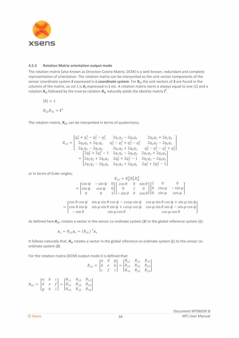
Document MT0605P.B © Xsens MTi User Manual
34
4.5.3 Rotation Matrix orientation output mode
The rotation matrix (also known as Direction Cosine Matrix, DCM) is a well-known, redundant and complete representation of orientation. The rotation matrix can be interpreted as the unit-vector components of the sensor coordinate system S expressed in L-coordinate system. For RLS the unit vectors of S are found in the columns of the matrix, so col 1 is XS expressed in L etc. A rotation matrix norm is always equal to one (1) and a rotation RLS followed by the inverse rotation RSL naturally yields the identity matrix I
3.
The rotation matrix, RLS, can be interpreted in terms of quaternions;
[
]
[
]
or in terms of Euler-angles;
[
] [
] [
]
[
]
As defined here
RLS, rotates a vector in the sensor co-ordinate system (S) to the global reference system (L):
( )
It follows naturally that, RSL rotates a vector in the global reference co-ordinate system (L) to the sensor co-ordinate system (S). For the rotation matrix (DCM) output mode it is defined that:
[
] [
]
[
] [
]

Document MT0605P.B © Xsens MTi User Manual
35
4.6 Sensor data performance specification
This section describes the specifications of the physical sensors of the MTi’s. Not all MTi’s feature all sensors. Per sensor, the applicable MTi’s are mentioned. For more detailed specifications, refer to [MTI_TD].
4.6.1 Gyroscopes
The main difference between the MTi 10-series and the MTi 100-series is the type of gyroscopes used. The two different specifications are listed below. A full range of 1000 º/s is available upon request (export restrictions may apply). Gyroscopes in MTi 10-series: MTi-10, MTi-20, MTi-30 Gyroscopes in MTi 100-series: MTi-100, MTi-200, MTi-300, MTi-G-700
4.6.2 Accelerometers and magnetometer
The MTi 10-series and MTi 100-series use the same accelerometers and magnetometer. The output of the magnetometer is in arbitrary units (a.u.), one a.u. is the magnetic field strength during calibration at Xsens’ calibration lab. This is approximately 40 uT. An accelerometer range of 15g is available as well. Accelerometers/magnetometer: all products: MTi-10, MTi-20, MTi-30, MTi-100, MTi-200, MTi-300, MTi-G-700
Gyroscopes specification MTi 10-series MTi 100-series
Rate of turn Typical Max Typical Max
Standard full range [deg/s] 450 - 450 -
Bias repeatability (1 yr) [deg/s] 0.2 0.5 0.2 0.5
In-run bias stability [deg/h] 18 - 10 -
Bandwidth (-3dB) [Hz] 415 N/A 450 N/A
Noise density [deg/s/√Hz] 0.03 0.05 0.01 0.015
g-sensitivity (calibrated) [deg/s/g] 0.006 0.02 0.003 0.015
Non-orthogonality [deg] 0.05 - 0.05 -
Non-linearity [% FS] 0.03 0.1 0.01 -
A/D resolution [bits] 16 N/A 16 N/A
Accelerometers and magnetometers specification MTi 10-series and MTi 100-series
Acceleration Typical Max
Standard full range [m/s2] 50 -
Bias repeatability (1 yr) [m/s2] 0.03 0.05
In-run bias stability [µg] 40 -
Bandwidth (-3dB) [Hz] 375 N/A
Noise density [µg/√Hz] 80 150
Non-orthogonality [deg] 0.05 0.05
Non-linearity [% FS] 0.03 0.5
A/D resolution [bits] 16 N/A
Magnetic fields
Full range [uT] - 80
Noise density [µGauss/√Hz] 200 -
Non-linearity [% FS] 0.1 -
A/D resolution [bits] 12 N/A

Document MT0605P.B © Xsens MTi User Manual
36
4.6.3 Barometer
The barometer features barometric (atmospheric) pressure. The MTi-100 series feature this barometer. The MTi 100-series has three holes with a protective vent in its casing in order to ensure fast adaptation inside the MTi to atmospheric pressure. Typical latency because of the vent is <10 ms. Barometer: MTi 100-series only: MTi-100, MTi-200, MTi-300, MTi-G-700
4.6.4 GPS receiver
The MTi-G-700 is the only MTi that features a GPS receiver. It requires an active antenna, which is delivered with the Development Kit and can be ordered separately from Xsens as well. It is possible to use a different antenna that better suits your application.
GPS Receiver specification MTi 100-series
Receiver Type: 50 channels GPS L1, C/A code
GPS Update Rate: 4 Hz
Pos/Vel Update Rate: 400 Hz
Horizontal Accuracy Position SPS: 2.5 m CEP
SBAS: 2.0 m CEP
Vertical Accuracy Position SPS: 5 m
Velocity accuracy 0.1 m/s @ 30 m/s
Start-up Time Cold start: 27 s
Re-acquisition: <1 s
Tracking Sensitivity: -161 dBm
Timing Accuracy: 30 ns RMS
Maximum Altitude: 18 km
Maximum Velocity: 515 m/s
Max dynamics GPS: 4 g
Note that when you are not using the default GPS antenna, it is important to use an antenna that is suitable for the MTi-G-700. Please consult www.xsens.com/en/support.
MTi 10-series MTi 100-series
Barometric pressure
N/A
Full range [hPa] - 300-1100
Noise density [hPa/√Hz] 0.01 -

Document MT0605P.B © Xsens MTi User Manual
37
4.7 Built-in self-test
All MTi’s feature a built-in self-test (BIT). The self-test actuates the mechanical structures in the MEMS accelerometer and gyroscope by inducing an electric signal. This allows checking the proper functioning of the mechanical structures in the MEMS inertial sensors as well as the signal processing circuitry. In the magnetometer, a magnetic field is induced by a coil designed around the component, which will generate an offset in the signal. During self-test the MTi will read out all sensors and in case of a successful self-test, a known offset with respect to the signal prior to enabling self-test should be visible in the data. The MTi will internally evaluate the sensors readings, the self-test will return the status of the self-test per individual sensor. The status is stored into the non-volatile memory. A passed self-test will result in a valid self-test flag in the status byte. Because the self-test influences the sensor data, the self-test is only available in Config mode. For more information, refer to [LLCP], function RunSelftest.

Document MT0605P.B © Xsens MTi User Manual
38
4.8 Test and Calibration Certificate
Each MTi is accompanied by an individual Test and Calibration Certificate. This certificate states the calibration values determined during the calibration of the MTi at Xsens’ calibration facilities. The values are explained here in short: The “IMU specifications” chapter contains the full ranges and bandwidths of the physical sensors inside. The “Basic test results” describes the noise of the all internal sensors and contains residuals in orientation. “Calibration data” are the values that describe the conversion from the physical phenomenon to a digital output in an orthogonal coordinate system: Gains (bits): Gains (or scale factor) describe the relation between the digital reading in bits and the measured physical signal. Offsets (bits): Digital reading in bits of the sensor when no physical signal is measured. Alignment matrix: Non-orthogonality of the sensor triade. This includes non-orthogonality in the orientation of the sensitive system inside the MEMS sensor, the mounting of the sensors on the PCB of the MTi, the mounting of the PCB’s and the misalignment of the OEM board in the MTi housing. Next to the basic Test and Calibration values documented in the certificate, each device is calibrated according to more complicated models to ensure accuracy (e.g. non-linear temperature effect, cross coupling between acceleration and angular rate10).
10
Also known as “g-sensitivity”.

Document MT0605P.B © Xsens MTi User Manual
39
4.9 Sensors data outputs
4.9.1 Physical sensor model
This section explains the basics of the individual calibration parameters of each MTi. This explains the values found on the MT Test and Calibration Certificate that comes with each MTi. The physical sensors inside the MTi (accelerometers, gyroscopes and magnetometers) are all calibrated according to a physical model of the response of the sensors to various physical quantities, e.g. temperature. The barometer and GPS receiver do not require calibration. The basic model is linear and according to the following relation:
( )
The model really used is more complicated and is continuously being developed further. From factory calibration each MTi has been assigned a unique gain matrix, KT and the bias vector, bT This calibration data is used to relate the sampled digital voltages, u, (unsigned integers from the 16 bit ADC’s) from the sensors to the respective physical quantity, s. The gain matrix is split into a misalignment matrix, A, and a gain matrix, G. The misalignment specifies the direction of the sensitive axes with respect to the ribs of the sensor-fixed coordinate system (S) housing. E.g. the first accelerometer misalignment matrix element a1,x describes the sensitive direction of the accelerometer on channel one. The three sensitive directions are used to form the misalignment matrix:
[
] [
]
[
] [
]
With O representing higher order models and temperature modelling, g-sensitivity corrections, etc. Each individual MTi is modeled for temperature dependence of both gain and bias for all sensors and other effects. This modeling is not represented in the simple model in the above equations, but is implemented in the firmware. The basic indicative parameters in the above model of your individual MTi can be found on the MT Test and Calibration Certificate and in the MT Manager (MT Settings dialog).

Document MT0605P.B © Xsens MTi User Manual
40
4.9.2 Calibrated delta_q and delta_v outputs
This output is coning- and sculling compensated strap down integrated data in the sensor-fixed coordinate system (S) or (O). Note that the value of the output depends on the output frequency, as the values are integrated over a specific time. Delta_q can also be noted as dq, delta_angle, del_q or OriInc. Delta_v can also be noted as dv, delta_velocity, del_v or VelInc.
Output
Delta_q (DataID 0x8030) a.u. (quaternion values)
Delta_v (DataID 0x4010) m/s
It is possible to multiply consecutive delta_q values to find the total orientation change over a specific period. Note that this data is not drift free, as it has not been processed by the sensor fusion filters. Use the orientation output for drift free orientation.
4.9.3 Calibrated inertial and magnetic data outputs
Output of calibrated 3D linear acceleration, 3D rate of turn (gyro) and 3D magnetic field data is in sensor-fixed coordinate system (S) or (O). The units of the calibrated data output are as follows:
Vector Unit
Acceleration m/s2
Angular velocity (rate of turn) rad/s
Magnetic field a.u. (arbitrary units) normalized to earth field strength
Calibrated data has been going through Strapdown Integration and Inverse Strapdown Integration.
4.9.4 Free acceleration
Free acceleration (Data ID 0x4030) is the acceleration of which gravity is deducted. Output is in m/s2.

Document MT0605P.B © Xsens MTi User Manual
41
4.9.5 Uncalibrated raw output mode
The MTi can output sensor component readout (SCR), i.e. digitized voltages of all sensors, before they are filtered or calibrated using Xsens’ proprietary firmware and calibration parameters. These sensors are the gyroscopes (rate of turn), accelerometers (acceleration), magnetometer (magnetic field), barometer (static pressure) and temperatures (gyroscope temperatures and a general temperature sensor). When selecting sensor component readout, the following outputs are available:
Sensor Digital/analog Unit Maximum frequency
Gyroscopes Analog, not through ADC 2-byte integer 2000 Hz
Accelerometers Analog, not through ADC 2-byte integer 2000 Hz
Magnetometer Digital a.u. 100 Hz
Barometer Digital Pa 50 Hz
Temperature sensors Analog, through ADC ºC 1 Hz
Note that these SCR-values of the gyroscopes and accelerometers are not calibrated for offset, gain, misalignment and temperature. Also, coning and sculling compensation is not applied. It is possible to post-process SCR data with MT Manager, and this output is very suitable if you need to perform your own calibration. Note that this output cannot be combined with any other output.

Document MT0605P.B © Xsens MTi User Manual
42
4.10 Legacy output messages
The MTi 10-series and MTi 100-series are Xsens’ 4th
generation MTi (MkIV). The 2nd
and 3rd
generation products have been released in 2005 and 2008. The 4
th generation can be distinguished by their aluminium casing (or
orange PCB if you are using an OEM). A photo of the 4th
generation MTi can be found on the cover of this manual. The MTi 10-series and MTi 100-series use the same XBus communication protocol as legacy MTi’s, MTx’s and MTi-G’s (see photo on the right). However, because of increased functionality and a different signal processing pipeline, the MTi 10-series and MTi 100-series are not drop-in replaceable in all cases. It is possible to configure the MTi’s in such a way that they are drop-in replaceable in some programs that are based on legacy classes and source code. Note that it is only possible to use the MTi in legacy mode when data is processed onboard the MTi. It is not possible to process raw data (16-bit binary data) with legacy source code into orientation, position or dynamic data. All outputs are only available at frequencies that can be are integer divisions of 400 Hz (400 Hz, 200 Hz, 100 Hz, 80 Hz, etc). The following outputs are available in the MTi legacy data message:
Available ‘legacy’ output modes
Orientation
Quaternions ENU
Euler angles ENU
Rotation Matrix ENU
Calibrated data
Rate of turn
Acceleration
Magnetic Field Note that at a frequency higher than 100 Hz, magnetometer data will be sent out duplicate (200 Hz will result in two duplicate values; 400 Hz will result in 4 duplicate values)
Timestamp
Sample counter 16-bits, wraps after 65536 samples
UTC MTi-G-700 only
Position and velocity
3D Position LLA
3D Velocity ENU
Status
Status byte Self test, valid XKF, GPS-fix (MTi-G-700), NoRotation status
Figure 9: Legacy MTi/x product range
(3rd generation)
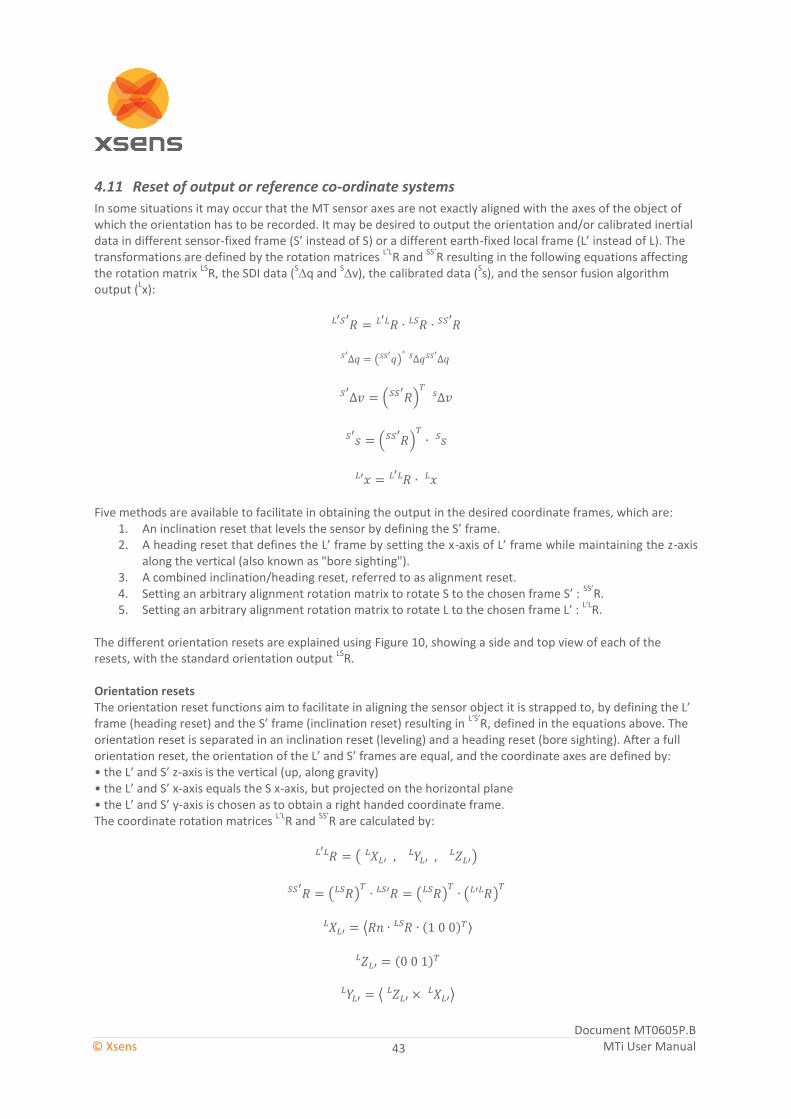
Document MT0605P.B © Xsens MTi User Manual
43
4.11 Reset of output or reference co-ordinate systems
In some situations it may occur that the MT sensor axes are not exactly aligned with the axes of the object of which the orientation has to be recorded. It may be desired to output the orientation and/or calibrated inertial data in different sensor-fixed frame (S’ instead of S) or a different earth-fixed local frame (L’ instead of L). The transformations are defined by the rotation matrices
L’LR and
SS’R resulting in the following equations affecting
the rotation matrix LS
R, the SDI data (S∆q and
S∆v), the calibrated data (
Ss), and the sensor fusion algorithm
output (Lx):
( )
( )
( )
Five methods are available to facilitate in obtaining the output in the desired coordinate frames, which are:
1. An inclination reset that levels the sensor by defining the S’ frame. 2. A heading reset that defines the L’ frame by setting the x-axis of L’ frame while maintaining the z-axis
along the vertical (also known as "bore sighting"). 3. A combined inclination/heading reset, referred to as alignment reset. 4. Setting an arbitrary alignment rotation matrix to rotate S to the chosen frame S’ :
SS’R.
5. Setting an arbitrary alignment rotation matrix to rotate L to the chosen frame L’ : L’L
R.
The different orientation resets are explained using Figure 10, showing a side and top view of each of the resets, with the standard orientation output
LSR.
Orientation resets The orientation reset functions aim to facilitate in aligning the sensor object it is strapped to, by defining the L’ frame (heading reset) and the S’ frame (inclination reset) resulting in
L’S’R, defined in the equations above. The
orientation reset is separated in an inclination reset (leveling) and a heading reset (bore sighting). After a full orientation reset, the orientation of the L’ and S’ frames are equal, and the coordinate axes are defined by: • the L’ and S’ z-axis is the vertical (up, along gravity) • the L’ and S’ x-axis equals the S x-axis, but projected on the horizontal plane • the L’ and S’ y-axis is chosen as to obtain a right handed coordinate frame. The coordinate rotation matrices
L’LR and
SS’R are calculated by:
(
)
( ) ( )
( )
⟨ ( ) ⟩
( )
⟨
⟩

Document MT0605P.B © Xsens MTi User Manual
44
After an inclination and/or heading reset, the equation for L’S’
R is applied (see above). It should be noted that the inclination reset (
SS’R) will not work if the sensor x-axis is aligned along the z-axis of the object, since the
sensor x-axis is used to describe the direction of the object x-axis. Furthermore, after a heading reset, the yaw may not be exactly zero, especially when the x-axis is close to the vertical. This is caused by the definition of yaw in Euler angles, which becomes unstable when the pitch approaches 90 deg.
Figure 10: Top view and side view of an MT with coordinate frame S (left) strapped to an object and local frame L. The different alignments and resets define the S’ and/or L’ frame. (a): the default orientation output of S with respect to L: LSR; (b): after inclination reset, method 1: LS’R (c): after heading reset, method 2: L’SR, (d): after alignment reset, method 3: L’S’R. All of these are also possible to set with arbitrary alignments.
NWU and NED reference coordinate frames The default reference coordinate frame in the MTi is ENU-frame, described in section 4.2.3, the MTi supports two other reference coordinate systems that can be selected. These are NWU and NED. NWU is the reference coordinate system that used to be the default up to the third generation MTi and MTi-G. In order to configure the MTi to output in the NWU local frame, apply the following rotation matrix in RotLocal.
[
]
NED is a reference coordinate system often used in aerospace applications. NED is also a reference coordinate system available in the third generation MTi and MTi-G. In order to configure the MTi in NWU, apply the following two rotation matrices:

Document MT0605P.B © Xsens MTi User Manual
45
[
]
Arbitrary alignment If the measured kinematics is required in a frame S’ and/or a frame L’ with known orientations with respect to standard sensor coordinate frames S and L, the alignment matrices can be set with an arbitrary but known orientation. This can be useful if for mechanical reasons the MT can only be fastened in some specific orientation. The alignment matrices
L’LR or
SS’R are applied to the output data according to the equations above.
Refer to the MT Manager User Manual on how to use these alignment matrices. The different orientation resets can be summarized as follows
- Inclination reset: Applying SS’
R only - Heading reset: Applying
L’LR only
- Alignment reset: Applying both L’L
R, and SS’
R

Document MT0605P.B © Xsens MTi User Manual
46
4.12 Timestamp and packet counter output
Each data message can be accompanied by a packet counter and/or timestamp.
4.12.1 Packet counter
The packet counter is an incremental number that comes with each packet, regardless of what data is in the packet. It can also mean that time differences between packet counters may not be the same. Note that the packet counter is a good indication if data is missed during transmission of the data, as the packet counters are created when generating (composing) a data message prior to sending.
4.12.2 Time UTC
Time UTC is time in the format of UTC, it does not have to be necessarily UTC synchronized. The format is described below:
DATA (B) Description
0 Nanoseconds of second, range 0 .. 1.000.000.000
4 Year, range 1999 .. 2099
6 Month, range 1..12
7 Day of Month, range 1..31
8 Hour of Day, range 0..23
9 Minute of Hour, range 0..59
10 Seconds of Minute, range 0..59
11 0x01 = Valid Time of Week
0x02 = Valid Week Number
0x04 = Valid UTC
When outputted, the Time UTC starts as following:
- At 0.0 sec, unless
- A time is available in the non-volatile memory, unless
- GPS time is available (MTi-G-700 only)
When the time stamp wraps over 0.00h (midnight), the date progresses a day.
4.12.3 Time stamp (Sample Time Fine)
The time stamp is a 0.1 ms resolution 4 byte time stamp. The start time is the following:

Document MT0605P.B © Xsens MTi User Manual
47
4.13 Status byte
The status byte includes information about the status of the MTi, its sensors, the filter and user inputs. The following information can be found in the status byte and status word: Status byte (DataID 0xE010) is the short status byte (8 bits), identical to the status byte of the legacy output message (see section 4.10). Status word (DataID 0xE020) is an extended 32 bits status message. The bits in StatusWord are defined in the following table (note that bit 0:7 are the same as Status Byte):
Bits Field Description
0 Selftest This flag indicates if the MT passed the latest self-test (RunSelftest).
1 Filter Valid This flag indicates if input into the filter orientation filter is reliable and / or complete. If for example the measurement range of internal sensors is exceeded, orientation output cannot be reliably estimated and the filter flag will drop to 0. For the MTi-G, the filter flag will also become invalid if the GPS status remains invalid for an extended period
2 GPS fix This flag indicates if the GPS unit has a proper fix. The flag is only available in MTi-G units.
3:4 NoRotationUpdate Status (only available for legacy devices): This flag indicates the status of the no rotation update procedure in the filter after the SetNoRotation message has been sent.
11: Running with no rotation assumption 10: Error: Rotation detected, procedure not started (sticky) 01: Estimation complete, some samples rejected (sticky) 00: Estimation complete, no errors
5 Timestamp GPS synced
6 Timestamp clock synced
7 On/Off
8 Clipflag Acc X If set an out of range acceleration on the X axis is detected
9 Clipflag Acc Y If set an out of range acceleration on the Y axis is detected
10 Clipflag Acc Z If set an out of range acceleration on the Z axis is detected
11 Clipflag Gyr X If set an out of range angular velocity on the X axis is detected
12 Clipflag Gyr Y If set an out of range angular velocity on the Y axis is detected
13 Clipflag Gyr Z If set an out of range angular velocity on the Z axis is detected
14 Clipflag Mag X If set an out of range magnetic field on the X axis is detected
15 Clipflag Mag Y If set an out of range magnetic field on the Y axis is detected
16 Clipflag Mag Z If set an out of range magnetic field on the Z axis is detected
17:18 NoVelocityUpdate status
19 Clipping indication This flag indicates going out of range of one of the sensors (is set when one or more bits from 8:16 are set)
20 Reserved Reserved for future use
21 SyncIn Marker When a SyncIn is detected, this bit will rise to 1
22 SyncOut Marker When SyncOut is active this bit will rise to 1
23:25 Filter mode Only available for MTi-G-700 000: Without GPS (filter profile is in VRU mode) 001: Coasting mode (GPS has been lost <60 sec ago) 011: With GPS (default mode of MTi-G-700)
26:31 Reserved Reserved for future use

Document MT0605P.B © Xsens MTi User Manual
48
5 Basic communication
5.1 Introduction
This section describes the basics of how to communicate with the MTi directly on low-level using RS-232/422/485 serial communication or USB. For a detailed and complete list of all messages please refer to the MT Low-level Communication Documentation. NOTE: You can skip this chapter if you plan to only interface with the device using Xsens’ MT Manager GUI software or SDK API. The communication protocol, which is message based, enables the user to change the configuration of the MTi and to retrieve the data from the device. The communication protocol used for the MTi is mostly compatible with legacy MTi and MTx devices. The configuration is fully user-settable, e.g. data output modes, in- & output synchronization, baud rate, can all be changed to fit your requirements. All configuration changes must be made while the device is in the so-called Config State. In this state the device accepts messages that set the output mode or changes to other settings. Whenever the preferred configuration is completed the user can set the device to Measurement State. In this state the device outputs data based the current configuration settings.
5.2 States
The MTi has two states, i.e. Config State and Measurement State. In the Config State various settings can be read and written. In the Measurement State the device will output its data message which contains data dependent on the current configuration. There are two different ways to enter the Config State or the Measurement State. At power-up the device starts the WakeUp procedure, if no action is taken it will then enter Measurement State by default, using its latest stored configuration. Prior to entering the Measurement State, the Configuration and eMTS
(extended Motion Tracker Specification messages are always sent to the host. Configuration data is the configuration that is read from the internal non-volatile memory and will be used in the Measurement State. The data in the Configuration message can always be used to determine the output mode and settings. It
is also possible to enter the Config State at power-up, see WakeUp message description in the MT Low-Level
Communication Document. Another way to enter the Config State or Measurement State is to use the GoToConfig or GoToMeasurement messages. The eMTS data is required to be able to later process the
data by Xsens software to calculate calibrated inertial data values as well as estimating orientation etc. The default configuration of the MTi is shown in the following table.
Measurement
WakeUp
procedure
WakeUpAck
received by device
No WakeUpAck
received by device
GotoMeasurement
GotoConfig
Config
Property Value
Output data and frequency Orientation-quaternion legacy @ 100 Hz Sample Counter @ 100 Hz
Baud rate 115k2 bps (serial), for USB not applicable

Document MT0605P.B © Xsens MTi User Manual
49
5.3 Messages
5.3.1 Message structure
The communication with the MTi is done by messages which are built according to a standard structure. The standard MT message can contain zero to 254 bytes of data and the total length is five to 259 bytes. An MT message contains the following fields:
BID MID LEN DATAPRE CS
Preamble (PRE) Every message starts with the preamble. This field always contains the value 250 (=0xFA). Bus identifier (BID) or Address All messages used for the MTi and MTx use the address value 255 (0xFF) indicating a “master device”. MT’s used on the Xbus have other BID’s. Message Identifier (MID) This message field identifies the kind of message. For a complete listing of all possible messages see MTi and MTx Low-Level Communication Document. The message MTData2 is explained in section 5.3.3. Length (LEN) Specifies the number of data bytes in the DATA field. Value 255 (=0xFF) is reserved. This means that a message has a maximum payload of 254 bytes. If Length is zero no data field exists. Data (DATA) This field contains the data bytes and it has a variable length which is specified in the Length field. The interpretation of the data bytes are message specific, i.e. depending on the MID value the meaning of the data bytes is different. See the description of the specific message for more details about interpretation of the data bytes. Checksum This field is used for communication error-detection. If all message bytes excluding the preamble are summed and the lower byte value of the result equals zero, the message is valid and it may be processed. The checksum value of the message should be included in the summation.
5.3.2 Message usage
Generally, a message with a certain MID value will be replied with a message with a MID value that is increased by one, i.e. the acknowledge message. Depending on the type of message the acknowledge message has no or
Field Field width Description
PRE 1 byte Preamble, indicator of start of packet 250 (0xFA)
BID 1 byte Bus identifier / address 255 (0xFF)
MID 1 byte Message identifier
LEN 1 byte Value equals number of bytes in DATA field Maximum value is 254 (0xFE). Value 255 (0xFF) is reserved.
DATA 0 – 254 bytes Data bytes (optional)
CS 1 byte Checksum of message

Document MT0605P.B © Xsens MTi User Manual
50
a certain number of data bytes. In some cases an error message will be returned (MID = 66 (0x42)). This occurs in case the previous message has invalid parameters, is not valid, or could not be successfully executed. An error message contains an error code in its data field. Example Requesting the device ID of an MTi: Sending message: ReqDID = 0xFA 0xFF 0x00 0x00 0x01 (hexadecimal values)
Receiving message (= Acknowledge): DeviceID = 0xFA 0xFF 0x01 0x04 HH HL LH LL CS (hexadecimal values)
The requested Device ID is given in the acknowledged message DeviceID (here shown as: HH HL LH LL, the
checksum is CS). As you can see the MID (Message ID) of the acknowledgement is increased by one in comparison with the sending message ReqDID.
Some messages have the same MID and depending on whether or not the message contains the data field the meaning differs. This is the case with all the messages that refer to changeable settings. For example, the MID of message requesting the output mode (ReqOutputMode) is the same as the message that sets the output
mode (SetOutputMode). The difference between the two messages is that the Length field of
ReqOutputMode is zero and non-zero for SetOutputMode.
Example Request current output mode: Sending message: ReqBaudrate = 0xFA 0xFF 0x18 0x00 0xE7 (hexadecimal values)
Receiving message (= Acknowledge): ReqBaudrateAck = 0xFA 0xFF 0x19 0x01 BR CS (hexadecimal values)
ReqBaudrateAck contains data which represents the current mode (= BR). CS stands for the checksum
value. To change the baud rate you must add the baud rate in the data field of the sending message: Set the output mode: Sending message: SetBaudrate = 0xFA 0xFF 0x18 0x01 BR CS (hexadecimal values)
Receiving message (= Acknowledge): SetBaudrateAck = 0xFA 0xFF 0x19 0x00 0xE8 (hexadecimal values)

Document MT0605P.B © Xsens MTi User Manual
51
5.3.3 Common messages
GoToConfig MID 48 (0x30) Data field n/a Direction To MTi Valid in Measurement State & Config State
Switches the active state of the device from Measurement State to Config State. This message can also be used in Config State to confirm that Config State is currently the active state.
SetOutputConfiguration MID 192 (0xC0) DATA OutputConfig (N*4 bytes) Valid in Config State
Set the output configuration of the device. This supersedes SetPeriod, SetOutputSkipFactor, SetOutputMode and SetOutputSettings. The data is a list of maximum 32 data identifiers combined with a desired output frequency. The response message contains a list with the same format, but with the values actually used by the device. Each entry in the list contains:
Offset Value
0 Data Identifier (2 bytes)
2 Output Frequency (2 bytes)
A full list of all Data Identifiers can be found in the MT Low Level Communication Protocol documentation (under SetOutputConfiguration).
GoToMeasurement MID 16 (0x10) Data field n/a Direction To MTi / MTx Valid in Config State
Switches the active state of the device from Config State to Measurement State. The current configuration settings are used to start the measurement.
MTData2 MID 54 (0x36) DATA DATA (length variable) Direction To host Valid in Measurement State The MTData2 message contains output data according the current OutputConfiguration. Unlike the legacy MTData message an MTData2 message does not have to contain all configured output all the time. Instead of a single fixed output format for a particular configuration an MTData2 message consists of one or more packets, each containing a specific output.

Document MT0605P.B © Xsens MTi User Manual
52
The layout of an MTData2 message is shown below:
The payload of the message consists of multiple (N) packets. Each packet starts with a two byte Data Identifier followed by a one byte Size field. After that follows the Packet Data that is Size bytes long. The Data Identifier determines the format of the Packet Data. This packet scheme makes the output data format very flexible. If a particular output data is not available the packet is omitted from the message. Also if during parsing of the message an unknown Data Identifier is encountered the packet can be skipped using its Size field. It allows for more optimal bandwidth usage and simplifies keeping future devices and/or software backwards compatible. In the MT Low Level Communication Protocol documentation, format descriptions of all data packets are described.

Document MT0605P.B © Xsens MTi User Manual
53
5.4 Communication Timing
For many applications it can be crucial to know exactly the various delays and latencies in a system. In this section it is described how the timing between physical events and the device output are related in the basic usage modes of the MTi When the MTi is in Measurement State, the internal processor core continuously controls a signal processing pipeline, roughly according to the above diagram. Outputting data can be triggered by the device internal clock, or by external software triggers (polling), or hardware triggers. For more information about triggering see section 5.5. Note that sampling of the sensors cannot be externally triggered because of the high sampling rate of 10 kHz. It is possible to adjust the internal sampling clock though by using the ClockSync functionality (see section 5.5.4). The time delay between a physical event (e.g. an orientation change or acceleration) is dictated by two factors;
1. Internal acquisition, calculation time and message generation (signal processing duration) 2. Serial transmission time
Thanks to the system architecture of the Xsens sensor fusion algorithm, the signal processing duration is independent of the filter profile. Using a multi-core processing unit, it is possible to bring down the total time from physical event to data transmission on the USB or serial output to far below 2 ms. The serial transmission time can easily be calculated when the byte message and the baud rate is known:
( )
( )
These two factors will be discussed using the example of two common output configurations of the MTi. The bytes in the message consist of the Preamble, BusID, MessageID, length indicator, data itself and the checksum:
The Preamble, BusID, MesssageID, length indicator and checksum together is always 5 bytes. The length of the various data messages is discussed in [LLCP]. Example 1: Euler angels orientation data at 400 Hz and SDI data (delta_q and delta_v) at 100 Hz with a baud rate of 230400 bps (RS232).
PREAMBLE BID MID LEN DATA CHECKSUM
Sensor fusion Physical calibration Sampling
and ADC
Output formatting and
message generation
Data
Triggering
Hardware/software triggers

Document MT0605P.B © Xsens MTi User Manual
54
Euler angles is 12 bytes, SDI data is 24 bytes. This means that there will be one message of 41 bytes, followed by three messages of 17 bytes, and then one message of 41 bytes again.
( )
( )
Note that, although the average data stream is lower than the baud rate, it is not possible to choose a baud rate lower than 230400 bps in this particular case, as data comes at 400 Hz (every 2.5 ms) and the longest transmission time at a baud rate of 115200 bps would be 3.56 ms. Example 2: Quaternion data output at 100 Hz with a baud rate of 921600 bps (RS232). Quaternion data is 16 bytes.
( )
USB communication timing When the MTi is used with the USB cable, much of the timing depends on the scheduling of the host (e.g. Windows) as the host needs to poll data from the USB devices. For real time interfaces, a serial interface (RS232, RS422 or RS485) is recommended.

Document MT0605P.B © Xsens MTi User Manual
55
5.5 Triggering and synchronization
In case multiple systems are used during a measurement it is important to have the measurement data synchronized between the systems. Processing synchronised data is much easier because there is no need to resample the data to compensate for timing inaccuracies like clock drift and clock deviations. Synchronization using multiple systems involves 2 important issues: starting the measurement at the same time and having a fixed time relationship of the sampling instances. This section will explain how the MTi must be setup when using multiple measurement systems. All MTi’s have a minimum of 3 GPIOs, offering the MTi capabilities to be triggered by external devices, trigger external devices or synchronize clock drift. These three user scenarios are explained in the following subsections.
5.5.1 External device triggers MTi (Send Latest)
In the following figure, a possible configuration is shown where a Motion Tracker and Device A are synchronised. In this example, a clock generator triggers device A and an MTi ensuring that the two devices are synchronized with each other.
The output of the clock generator can be directly connected to the MTi. NOTE: Always check if the SyncIn specification matches with the trigger signal. Once a SyncIn signal is received, the MTi will output the latest available data. It is possible to delay the data to be sent, to choose whether the SyncIn signal needs to be triggered on rising edge or falling edge etc. The internal clock determines when data is available. This data is transmitted only if a trigger is detected on the SyncIn line. This means that the trigger instance will not coincide with the availability of the data. Because two different clocks are used the time difference between the trigger instance and the last sampling instance may vary during the measurement and at most with a time equal to the used sampling period.
5.5.2 Marker in MT data (Trigger Indication)
Next to let the MTi send data to the computer, it is also possible to incorporate a trigger indication in the MTData2 packet (Status Word). The data will not be affected by the trigger indication; the data is marked with the pulse received.

Document MT0605P.B © Xsens MTi User Manual
56
5.5.3 MTi triggers external devices (Interval Transition Measurement)
In case the clock specification of the MTi is accurate enough for the measurement, the MTi can provide a sync pulse which is generated based on its internal clock. For more details on clock accuracy see section 5.6. A SyncOut marker is outputted in the data stream that shows the exact time of the transmission of the SyncOut pulse. The signal can be set to either pulse or toggle mode and in case of pulse mode the polarity can be set to negative or positive. For more information about enabling SyncOut and its settings see [LLCP]. To connect the SyncOut signal to an external device you can either make a custom cable that wires the SyncOut pin (see section 6.3.1.2) directly from the MTi/MTi-OEM or in case you use the CA-MP-MTI cable you can connect directly to the appropriate pin of the Molex header.
NOTE: Always check if the input voltage levels and the input impedance of the external device matches the SyncOut specifications.
5.5.4 Clock synchronization (Clock Bias Estimation)
The MTi features clock synchronization: it is possible to adjust the bias of the MTi’s internal clock with an external clock of which the frequency is known. Note that the adjusted bias is also used in the calibration of the inertial sensors, so that no additional errors are introduced. When a pulse is missed, e.g. because it was not sent or was lost on the input line, this will not have a bad influence on the performance. The maximum time that the pulses may be absent is 30 seconds. The clock synchronization can be used for two distinctive use cases:
When a precise external clock is available (e.g. a GPS time pulse), this frequency can be sent to the MTi to make sure that the time of the MTi follows the UTC time.
When an external device has a time constant that differs from the MTi, the sensor readings will at some point no longer be aligned to each other. If the external device accepts synchronization pulses, it is possible to use SyncOut; if the external device can send synchronization pulses at a frequency that is the same as the required output frequency of the MTi, it is possible to use SyncIn. If these two options are not possible, the Clock Sync is an alternative.
Specification Value
MTi’s internal clock accuracy 10 ppm
Input frequency 0.1 – 1000 Hz
Maximum deviation from MTi’s internal clock 900 ppm
Initialisation time (per ppm difference between internal clock and external clock)
0.72 ms/ppm

Document MT0605P.B © Xsens MTi User Manual
57
5.5.5 Combining synchronization functions
It is possible to configure multiple synchronization functions on the MTi. This can be useful if you need to synchronize multiple devices, e.g. a GPS device (providing a 1 pulse per second (PPS) pulse), an MTi-300 and an external camera that needs 0.2 seconds to make a picture.
In this example, you could use the GPS pulse to synchronize the clock of the MTi with the GPS clock (use Clock Bias Estimation), but you also need to know the timing difference between the GPS and MTi (so connect the 1 PPS to Trigger Indication as well: the 1 PPS trigger will be inside the MT Data2 packet). If you need orientation at a different rate than the camera images, you can send the Interval Transition Measurement (SyncOut) at a SkipFactor and with an offset to give the camera time to make the picture.

Document MT0605P.B © Xsens MTi User Manual
58
5.6 Internal clock accuracy
5.6.1 Clock of MTi’s without GPS receiver
The internal clock jitter of the MTi is less than 25ns. The internal clock of the MTi which generates the sample timing based on the set sample period is accurate to ±10 ppm with a maximum of ±15 ppm (this differs per MTi) over the temperature operating range. Using a typical MT (with an accuracy of 10 ppm), this means that the worst case deviation after a 1 hour log is ± 0.036 seconds (= 3600 s ∙ 10 ppm) or 15 sample counts in 1,440,000 at 400 Hz sample rate (± 25 ns/data packet @ 400 Hz).
5.6.2 Clock of MTi-G-700 GPS/INS
In the case that the MTi-G has a GPS fix the bias of the clock will be estimated and on the long term there will on average be no deviation from GPS time. On the short time scale, the clock jitter is the determining factor. The MTi-G is capable of generating a quite accurate hardware-synchronised time pulse when GPS is available. The time pulse is synchronised to UTC time. This accurate Time Pulse can be used to correct the sampling clock of the MTi-G. This clock bias estimation will improve the accuracy of the crystal used in the MTi-G, under normal operating conditions to below 1ppm. The time pulse used to correct the clock of the MTi-G has minor inaccuracies, caused by the following:
Delay caused by distance between antenna phase centre to input pin of the GPS receiver module in the MTi-G. The cable delay is 5.5ns/m for PFTE, resulting in 16.5ns delay with the development kit antenna (PCTel 3910D).
Quantisation loss, clock of 23.104MHz, results in a resolution of 43ns.
Rise time of Timepulse 7-25ns, best results when loaded with a high impedance.
Software delay, for handling the time pulse interrupt clock_ticks/300Mhz. The first point is compensated in the MT GPS receiver, but will vary with cable length. The internal clock jitter of the MTi is less than 25ns. The internal clock of the MTi which generates the sample timing based on the set sample period is accurate to ±10 ppm with a maximum of ±15 ppm (this differs per MTi) over the temperature operating range. f there is no GPS fix available. Using a typical MT (with an accuracy of 80 ppm), this means that the worst case deviation after a 1 hour log is ± 0.288 seconds (= 3600 s ∙ 80 ppm) or 29 sample counts in 360,000 at 100 Hz sample rate (± 0.8 μs/sample @ 100 Hz). In the case that the MTi-G has a GPS fix the bias of the clock will be estimated and on the long term there will on average be no deviation from GPS time. On the short time scale, the clock jitter is the determining factor. The MTi-G is capable of generating a quite accurate hardware-synchronised time pulse when GPS is available. The time pulse is synchronised to UTC time. This accurate Time Pulse can be used to correct the sampling clock of the MTi-G. This clock bias estimation will improve the accuracy of the crystal used in the MTi-G, under normal operating conditions to below 1ppm. The time pulse used to correct the clock of the MTi-G has minor inaccuracies, caused by the following :
Delay caused by distance between antenna phase centre to input pin of the GPS receiver module in the MTi-G. The cable delay is 5.5ns/m for PFTE, resulting in 16.5ns delay with the development kit antenna (PCTel 3910D).
Quantisation loss, clock of 23.104MHz, results in a resolution of 43ns.
Rise time of Timepulse 7-25ns, best results when loaded with a high impedance.
Software delay, for handling the time pulse interrupt clock_ticks/300Mhz. The first point is compensated in the MT GPS receiver, but will vary with cable length.

Document MT0605P.B © Xsens MTi User Manual
59
5.7 Default Serial Connection Settings
Setting Default Value
Bits/second (bps): 115200
Data bits: 8
Parity: none
Stop bits: 1
Flow control: none
These settings are the same for the RS-232 as the RS-422/RS485 versions. The baud rate (bps) setting can be changed by the user. The maximum is 921600 bps and the minimum 4800 bps. Please refer to the [LLCP] for details.
5.7.1 General definitions for binary data
All binary data communication is done in big-endian format. Example:
Un-calibrated 16 bits accelerometer output 1275 (decimal) = 0x04FB (hexadecimal) Transmission order of bytes = 0x04 0xFB
Calibrated accelerometer output (float, 4 bytes)
9.81 (decimal) = 0x411CF5C3 (hexadecimal) Transmission order of bytes = 0x41 0x1C 0xF5 0xC3
The bit-order in a byte is always:
[MSB…LSB] [bit 7 …bit 0]
5.7.2 Serial or USB communication
The MTi has a parallel serial and USB interface. However, it is not possible to have communication on both the serial and USB interfaces simultaneously. Therefore, the MTi wakes up as a serial device, unless USB is detected. When a USB interface is detected, the communication will be done via that USB interface.

Document MT0605P.B © Xsens MTi User Manual
60
6 Physical Specifications
6.1 Physical properties overview
All products of the MTi product range have the same mechanical and communication interfaces. Note that the RS422 version does not have an on-board USB interface.
6.2 Power supply
The nominal power supply of the MTi is 5V DC. The minimum operating supply voltage is >4.5V (for the external connector) and the absolute maximum is <40V.
The sensor works at a power supply of >4.5-34V. Use only SELV (Separated or Safety extra-low voltage) power supplies (double isolated) that are short-circuit proof.
The average operating power consumption is 530mW (~106 mA @ 5V) for the MTi 10-series. The average power consumption may vary slightly with usage mode (DSP load). Please note that efficiency of the power input stage will decrease with increasing supply voltage. At 3V3, the efficiency is optimal, at 30V DC the efficiency is around 65%.
The peak current at startup (power on) can be up to 200mA12.
When operated in room temperature the temperature inside the sensor will be 35-40°C in normal conditions.
11
Power consumption at 3V3 DC and 5V DC. Increasing baud rate from 115k2 to 460k8 will decrease 10% in power consumption for all configurations. Please note that efficiency of the power input stage will decrease with increasing supply voltage. At 3V3 DC the efficiency is optimal, at 30V DC the efficiency is around 65%. 12
If an alternative power supply is used check if it can supply these peak currents. Do not use a power supply if the peak supply current is lower than stated.
MTi 10-series MTi 100-series
MTi-##-%A#G# MTi-###-%A#G# MTi-G-700-%A#G#
Communication interface:
%=2: RS232 and USB %=4: RS485 and USB %=6: RS422 (no USB)
Additional interfaces: 3x SyncOut/SyncIn (GPIO)
Operating voltage: 4.5-30V or 3V3 (OEM only)
4.5-30V or 3V3 (OEM only)
4.5-30V or 3V3 (OEM only)
Power consumption11: (depending on output mode)
450 mW @ 3V3 530 mW @ 5V
550 mW @ 3V3 650 mW @ 5V
810 mW @ 3V3 960 mW @ 5V
Temperature Operating Range:
-40C - 85C -40C - 85C -40C - 85C
Specified performance Operating Range:
0C - 55C 0C - 55C 0C - 55C
Altitude operating range: N/A N/A -900 m - 9000 m (baro) <18000 m (GPS)
Maximum velocity: N/A N/A 0 - 515 m/s (GPS)
Outline Dimensions:
57 x 42 x 23 mm (W x L x H)
57 x 42 x 23 mm (W x L x H)
57 x 42 x 23 mm (W x L x H)
Weight: 52 g 52 g 55 g

Document MT0605P.B © Xsens MTi User Manual
61
6.3 Mechanical and electrical interface specifications
6.3.1 Encased MTi connectors overview
The MTi is available as OEM version and encased version. The encased version has an external 9-pins connection for power and data and one SMA connector for the antenna (MTi-G-700 only). The colour of the hexagonal nut, together with the colour of the base plate, indicates whether the MTi is an MTi 10-series or MTi 100-series. A grey/silver base plate and nut indicates an MTi 10-series, a dark grey/black base plate and nut indicates an MTi 100-series.
6.3.1.1 Power and data connection
For connection with the Fischer receptacle (Fischer part number: DBPU 102 A059-130), Xsens supplies two cables. The cable with product code CA-USB-MTi can be used to connect the MTi to any USB port (except for MTi’s with an RS422 interface). The cable with product code CA-MP-MTi allows access to all 9 pins of the Fischer connector on the MTi.
6.3.1.2 Pin configuration casing receptacle
CA-USB-MTi Connect the cable to the MTi and the USB cable to any USB port. Under Windows 7 and Windows XP, the Xsens USB driver will be automatically installed if not already installed. In order to lock the CA-MP-MTi to the casing (this will prevent vibration of the push-pull sleeve to be transferred to the casing and MEMS sensors), screw the round nut clockwise. Be sure not to tighten too fast. To unplug the CA-MP-MTi, screw the round locking counter clock wise and pull the connector out of the receptacle by sliding the sleeve of the connector backwards.
The connection between the Fischer connector and USB cable is given below.
Functionality Wire colour Fisher pin no. USB pin no. 10-pins OEM header
GND Black 1 4 4, 8
NC 2
NC 3
Vin Red 4 1 1
NC 5
NC 6
NC 7
USB DP (D+) Green 8 3 9
USB DM (D-) White 9 2 7
Fisher SV 102 A 059-130
2.90 m

Document MT0605P.B © Xsens MTi User Manual
62
CA-MP-MTi Cable CA-MP-MTi allows for full control of the MTi. Hardware synchronization options are available, as well as easy access to the serial interface. Although the USB connection wires of the CA-MP-MTi are connected it is not recommended to use the USB connection as the shielding of the CA-MP-MTi cable is not attached to the Molex header. In order to lock the CA-MP-MTi to the casing (this will prevent vibration of the push-pull sleeve to be transferred to the casing and MEMS sensors), screw the round nut clockwise. Be sure not to tighten too fast. To unplug the CA-MP-MTi, screw the round locking counter clock wise and pull the connector out of the receptacle by sliding the sleeve of the connector backwards.
Functionality Wire color Fisher pin no. Molex pin no. 10-pins MTi-OEM header
GND Black 1 2 4,8
RS232 TX / RS422_Z Yellow 2 4 5
RS232 RX / RS422_Y Grey 3 5 3
Vin (4.5-30V) Red 4 1 1
SyncIn Blue 5 7 2
SyncOut Pink 6 9 6
ClockSync Brown 7 8 10
USB DP (D+) / RS422_A Green 8 3 9
USB DM (D-) / RS422_B White 9 6 7
6.3.1.3 GPS Antenna
The MTi-G-700 has an onboard GPS receiver that needs an active antenna. This antenna can be connected to the SMA connector on the front panel of the MTi-G-700.
Rec
epta
cle
Molex
PicoBlade
Fisher SV 102 A 059-130
2.90 m

Document MT0605P.B © Xsens MTi User Manual
63
6.3.2 OEM connections overview
6.3.2.1 Power en data
All MTi’s are available as OEM-board as well. The connection from the OEM board to the push-pull connector of the encased version is a flexible PCB, which has put to vibration test according to MIL-STD 202. The OEM board contains two headers, one 10-pins header and one 14-pins header. Details of the headers are:
Description Manufacturer Part number
5x2 (10 pins dual row) box header, pitch 1.27 mm Samtec FTS-105-01-F-DV-P-K
7x2 (14 pins dual row) box header, pitch 1.27 mm Samtec FTS-107-01-F-DV-P-K
The two headers both have several functions, of which some are reserved for future use. The 10-pins header offers basic functionality, the 14-pins header features advanced options. Note that MTi’s with an RS422 interface don’t have a USB interface.
Pin Functionality Pin Functionality
10_1 Vin (4.5-34V) 14_1 GND
10_2 SyncIn 14_2 3V3 (to be implemented)
10_3 RS232 RX/RS422_Y 14_3 UART_TX (to be implemented)
10_4 GND 14_4 UART_RX (to be implemented)
10_5 RS232 TX/RS422_Z 14_5 GND
10_6 SyncOut 14_6 Reserved
10_7 USB DM (D-)/RS422_B 14_7 Reserved
10_8 GND 14_8 Reserved
10_9 USB DP (D+)/RS422_A 14_9 Reserved
10_10 ClockSync 14_10 Reserved
14_11 Reserved
14_12 GND
14_13 Reserved
14_14 Reserved
Pin 1 and 10 of the 10-pins header and pin 1 and pin 14 of the 14-pins header are labelled on the PCB.
6.3.2.2 GPS receiver
The MTi-G-700 GPS/INS needs an active antenna. The connection on the OEM board of the MTi-G-700 is done with a u.FL miniature coax.

Document MT0605P.B © Xsens MTi User Manual
64
6.3.2.3 Connecting with the OEM board
Connecting to the OEM board is possible by using sockets with a pitch of 1.27 mm. Notable manufacturers are Samtec, Molex and Hirose. Two examples of such sockets are:
Socket Manufacturer Part number Farnell part number
10-pins 1.27 mm pitch Samtec FFSD-05-01-N 1753841
14-pins 1.27 mm pitch Molex 90635-1143 1392991
These connectors can be connected to ribbon cables without tools to make a cable like below. On the right is an application of such a cable.
6.3.3 Additional interface specifications
The MTi has three GPIO lines on the main 10 pins connector (and thus on the 9-pins external Fischer connector). These 3 lines can be configured individually for synchronization purposes (see section 5.5). The three Sync lines are the following:
Name Fischer pin nr
OEM-1 pin nr
Value high/low Input resistance/ output load
Absolute max input
SyncIn 5 2 Low value: 0 - 0.8 V High value: 2.5 -20 V
Input resistance: ~100 kΩ 0-20V
SyncOut 6 6 Low value: 0 - 0.4 V High value: > 2.9 V
Output load: >330 Ω N/A
ClockSync 7 10 Low value: 0 - 0.8 V High value: 2.5 -20 V
Input resistance: ~100 kΩ 0-20V
For the descriptions of the synchronization functions, see [LLCP].

Document MT0605P.B © Xsens MTi User Manual
65
6.4 Housing mechanical specifications
The top casing of the MTi is made of anodized Aluminum 6060. The bottom plate is made of anodized Aluminum 6060 The MTi connector socket and housing assembly features rubber O-ring sealing. The MTi-100 series feature a vent that allows for the inside pressure to be the same as the ambient pressure without compromising the ingress protection.
6.4.1 Environmental protection of the housing
All encased MTi’s are designed to withstand usage in application where dust and occasional water splashing can be expected. However, Xsens in house testing has confirmed that the casing and connector can withstand temporary environmental circumstances equivalent to Protection Classification IP67 (sealed against dust, 30 minutes immersion at depth of 1 m).
6.4.2 Dimensions MTi
The MTi 10-series and the MTi 100-series (including MTi-G-700) have an identical footprint and (position of the) connector. Differences in casings are limited to colour, barometer holes (MTi 100-series only) and SMA connector (MTi-G-700 only).

Document MT0605P.B © Xsens MTi User Manual
66
6.4.3 MTi 10-series technical drawing
CAD drawings (STEP) are available at request via [email protected]

Document MT0605P.B © Xsens MTi User Manual
67
6.4.4 MTi 100-200-300 technical drawing
CAD drawings (STEP) are available at request via [email protected]

Document MT0605P.B © Xsens MTi User Manual
68
6.4.5 MTi-700-G technical drawing
CAD drawings (STEP) are available at request via [email protected]

Document MT0605P.B © Xsens MTi User Manual
69
7 Important notices
7.1 Safety instructions
It is recommended to study the instructions below
Do not place the MTi near strong magnetic fields.
Do not use cables or connectors other than described in this manual.
7.2 Absolute maximum ratings
Stresses above Absolute Maximum Ratings may cause permanent damage to the device. Shock (any axis): 20000 m/s
2 (2000 g) 0.5 ms (half-sine)
Input Voltage: -0.3 V … 40 V Interface inputs: -25 V … 25 V (RX, A and B inputs) SyncIn: 0 – 20 V
Operating/Storage Temperature: -40 C … 85 C Humidity: Casing is IP67 (for OEM: 95% max, non-condensing) Stresses beyond those listed here may cause permanent damage to the device. These are stress ratings only, and functional operation of the MTi at these or any other conditions beyond those indicated in section 4.6 of the specifications is not implied. Exposure to absolute maximum rating conditions for extended periods may affect device reliability. NOTE: Drops onto hard surfaces can cause shocks of greater than 20000 m/s
2 (2000 g) exceed the absolute
maximum rating of the device. Care should be taken when handling to avoid damage. Drops causing shock greater than absolute maximum ratings may not destroy the device but will permanently alter the properties of the physical motion sensors, which may cause the device to become inaccurate.
7.3 Maintenance
The MTi will not require any maintenance if properly used (see also section 7.1 and 7.2). However, if the Motion Tracker is not functioning according to the specifications please contact Xsens or your local distributor (www.xsens.com/support).

Document MT0605P.B © Xsens MTi User Manual
70
7.4 CE Declaration of Conformity for the MT devices
We, Xsens Technologies BV, of Pantheon 6a 7521 PR Enschede, The Netherlands declare under our sole responsibility that our products:
MTi-10-#A#G# (MTi-10-2A5G4, MTi-10-2A5G0, MTi-10-4A5G4, MTi-10-4A5G0, MTi-10-6A5G4, MTi-10-6A5G0, MTi-10-2A8G4, MTi-10-2A8G0, MTi-10-4A8G4, MTi-10-4A8G0, MTi-10-6A8G4, MTi-10-6A8G0)
MTi-20-#A#G# (MTi-20-2A5G4, MTi-20-2A5G0, MTi-20-4A5G4, MTi-20-4A5G0, MTi-20-6A5G4, MTi-20-6A5G0, MTi-20-2A8G4, MTi-20-2A8G0, MTi-20-4A8G4, MTi-20-4A8G0, MTi-20-6A8G4, MTi-20-6A8G0)
MTi-30-#A#G# (MTi-30-2A5G4, MTi-30-2A5G0, MTi-30-4A5G4, MTi-30-4A5G0, MTi-30-6A5G4, MTi-30-6A5G0, MTi-30-2A8G4, MTi-30-2A8G0, MTi-30-4A8G4, MTi-30-4A8G0, MTi-30-6A8G4, MTi-30-6A8G0)
MTi-100-#A#G# (MTi-100-2A5G4, MTi-100-2A5G0, MTi-100-4A5G4, MTi-100-4A5G0, MTi-100-6A5G4, MTi-100-6A5G0, MTi-100-2A8G4, MTi-100-2A8G0, MTi-100-4A8G4, MTi-100-4A8G0, MTi-100-6A8G4, MTi-100-6A8G0)
MTi-200-#A#G# (MTi-200-2A5G4, MTi-200-2A5G0, MTi-200-4A5G4, MTi-200-4A5G0, MTi-200-6A5G4, MTi-200-6A5G0, MTi-200-2A8G4, MTi-200-2A8G0, MTi-200-4A8G4, MTi-200-4A8G0, MTi-200-6A8G4, MTi-200-6A8G0)
MTi-300-#A#G# (MTi-300-2A5G4, MTi-300-2A5G0, MTi-300-4A5G4, MTi-300-4A5G0, MTi-300-6A5G4, MTi-300-6A5G0, MTi-300-2A8G4, MTi-300-2A8G0, MTi-300-4A8G4, MTi-300-4A8G0, MTi-300-6A8G4, MTi-300-6A8G0)
MTi-G-700-#A#G# (MTi-G-700-2A5G4, MTi-G-700-2A5G0, MTi-G-700-4A5G4, MTi-G-700-4A5G0, MTi-G-700-6A5G4, MTi-G-700-6A5G0, MTi-G-700-2A8G4, MTi-G-700-2A8G0, MTi-G-700-4A8G4, MTi-G-700-4A8G0, MTi-G-700-6A8G4, MTi-G-700-6A8G0)
to which this declaration relates, are in conformity with the essential requirements of the EMC Directive: 2004/108/EC and the following Standards and other Normative Documents: EMC Directive: 2004/108/EEC EN 61326-1 (2006) ; EN 61000-3-2 (2006); EN 61000-3-3 (1995) + A1 (2001) + A2 (2005) Environment to be used is light industrial/laboratory; Class of emission is B and performance criterion B. Dec 18
th 2012, Enschede, the Netherlands
Bart Kooi, PhD VP Engineering Xsens Technologies BV

Document MT0605P.B © Xsens MTi User Manual
71
7.5 FCC Declaration of Conformity for the MT devices
We, Xsens Technologies BV, of Pantheon 6a 7521 PR Enschede, The Netherlands declare under our sole responsibility that our products:
MTi-10-#A#G# (MTi-10-2A5G4, MTi-10-2A5G0, MTi-10-4A5G4, MTi-10-4A5G0, MTi-10-6A5G4, MTi-10-6A5G0, MTi-10-2A8G4, MTi-10-2A8G0, MTi-10-4A8G4, MTi-10-4A8G0, MTi-10-6A8G4, MTi-10-6A8G0)
MTi-20-#A#G# (MTi-20-2A5G4, MTi-20-2A5G0, MTi-20-4A5G4, MTi-20-4A5G0, MTi-20-6A5G4, MTi-20-6A5G0, MTi-20-2A8G4, MTi-20-2A8G0, MTi-20-4A8G4, MTi-20-4A8G0, MTi-20-6A8G4, MTi-20-6A8G0)
MTi-30-#A#G# (MTi-30-2A5G4, MTi-30-2A5G0, MTi-30-4A5G4, MTi-30-4A5G0, MTi-30-6A5G4, MTi-30-6A5G0, MTi-30-2A8G4, MTi-30-2A8G0, MTi-30-4A8G4, MTi-30-4A8G0, MTi-30-6A8G4, MTi-30-6A8G0)
MTi-100-#A#G# (MTi-100-2A5G4, MTi-100-2A5G0, MTi-100-4A5G4, MTi-100-4A5G0, MTi-100-6A5G4, MTi-100-6A5G0, MTi-100-2A8G4, MTi-100-2A8G0, MTi-100-4A8G4, MTi-100-4A8G0, MTi-100-6A8G4, MTi-100-6A8G0)
MTi-200-#A#G# (MTi-200-2A5G4, MTi-200-2A5G0, MTi-200-4A5G4, MTi-200-4A5G0, MTi-200-6A5G4, MTi-200-6A5G0, MTi-200-2A8G4, MTi-200-2A8G0, MTi-200-4A8G4, MTi-200-4A8G0, MTi-200-6A8G4, MTi-200-6A8G0)
MTi-300-#A#G# (MTi-300-2A5G4, MTi-300-2A5G0, MTi-300-4A5G4, MTi-300-4A5G0, MTi-300-6A5G4, MTi-300-6A5G0, MTi-300-2A8G4, MTi-300-2A8G0, MTi-300-4A8G4, MTi-300-4A8G0, MTi-300-6A8G4, MTi-300-6A8G0)
MTi-G-700-#A#G# (MTi-G-700-2A5G4, MTi-G-700-2A5G0, MTi-G-700-4A5G4, MTi-G-700-4A5G0, MTi-G-700-6A5G4, MTi-G-700-6A5G0, MTi-G-700-2A8G4, MTi-G-700-2A8G0, MTi-G-700-4A8G4, MTi-G-700-4A8G0, MTi-G-700-6A8G4, MTi-G-700-6A8G0)
to which this declaration relates, have been tested and found to comply with the limits for a Unintentional Radiator as described in 47 CFR 15 (2007 May, 04 Edition) Class B Digital Device, pursuant to Part 15 of the FCC Rules. Operation is subject to the following two conditions:
1. This device may not cause harmful interference, and 2. This device must accept any interference received, including interference that may cause
undesired operation. Dec 18
th 2012, Enschede, the Netherlands
Bart Kooi, PhD VP Engineering Xsens Technologies BV

Document MT0605P.B © Xsens MTi User Manual
72
7.6 Warranty and liability
Xsens Technologies B.V. warrants the products manufactured by it to be free from defects in material and workmanship for a period of 1 year from the date of delivery. Products not subjected to misuse will be repaired, replaced or credit issued at the sole option of Xsens Technologies B.V. Contact Xsens via www.xsens.com/support for return material authorization (RMA) prior to returning any items for calibration, repair or exchange. The product must be returned in its original packaging to prevent damage during shipping. The warranty shall not apply to products repaired or altered or removed from the original casing by others than Xsens Technologies B.V. so as, in Xsens Technologies B.V. opinion, to have adversely affected the product, products subjected to negligence, accidents or damaged by circumstances beyond Xsens Technologies B.V.’s control. NOTE: Xsens reserves the right to make changes in its products in order to improve design, performance, or reliability. Subject to the conditions and limitations on liability stated herein, Xsens warrants that the Product as so delivered shall materially conform to Xsens’ then current specifications for the Product, for a period of one year from the date of delivery. ANY LIABILITY OF XSENS WITH RESPECT TO THE SYSTEM OR THE PERFORMANCE THEREOF UNDER ANY WARRANTY, NEGLIGENCE, STRICT LIABILITY OR OTHER THEORY WILL BE LIMITED EXCLUSIVELY TO PRODUCT REPAIR, REPLACEMENT OR, IF REPLACEMENT IS INADEQUATE AS A REMEDY OR, IN XSENS' OPINION IMPRACTICAL, TO REFUND THE PRICE PAID FOR THE PRODUCT. XSENS DOES NOT WARRANT, GUARANTEE, OR MAKE ANY REPRESENTATIONS REGARDING THE USE, OR THE RESULTS OF THE USE, OF THE PRODUCT OR WRITTEN MATERIALS IN TERMS OF CORRECTNESS, ACCURACY, RELIABILITY, OR OTHERWISE. Xsens shall have no liability for delays or failures beyond its reasonable control.
7.7 Customer Support
Xsens is glad to help you with any questions you may have about the MTi, or about the use of the technology for your application. Please use the FAQ, contact Xsens’ distributor or if you are a direct customer of Xsens our Customer Support:
Internet and FAQ: http://www.xsens.com/support Distributror network: http://www.xsens.com/en/company-pages/company/distributors Telephone EMEA/Pacific: +31(0)88-9736700 (+31 88 XSENS 00) telephone US (Los Angeles, CA): +1 310-481-1800
To be able to help you, please mention your Motion Tracker Device ID (on the side of the device) and software license registration number in your e-mail.