MT190 Manual
12
INSTRUCTION MANUAL WARNING: For your personal safety, READ and UNDERSTAND before using. SAVE THESE INSTRUCTIONS FOR FUTURE REFERENCE. ENGLISH Power Planer MODEL MT190 004838 DOUBLE INSULATION
-
Upload
damien-butler -
Category
Documents
-
view
41 -
download
1
Transcript of MT190 Manual

I N S T R U C T I O N M A N U A L
WARNING:For your personal safety, READ and UNDERSTAND before using.SAVE THESE INSTRUCTIONS FOR FUTURE REFERENCE.
EN
GL
ISH
Power PlanerMODEL MT190
004838
DOUBLEINSULATION

2
SPECIFICATIONS
• Due to our continuing programme of research and development, the specifications herein are subject to changewithout notice.
• Note: Specifications may differ from country to country.
SYMBOLS END201-1
The following show the symbols used for the tool. Besure that you understand their meaning before use.
...................Read instruction manual.
...................DOUBLE INSULATION
Intended useThe tool is intended for planing wood.Power supplyThe tool should be connected only to a power supply ofthe same voltage as indicated on the nameplate, andcan only be operated on single-phase AC supply. Theyare double-insulated in accordance with EuropeanStandard and can, therefore, also be used from socketswithout earth wire.
Model MT190
Planing width 82 mm
Planing depth 1 mm
Shiplapping depth 6 mm
No load speed (min-1) 16,000
Overall length 290 mm
Net weight 2.5 kg
Safety class /II

3
GENERAL SAFETY RULES ENA100-1
WARNING:Read all instructions. Failure to follow all instructions listed below may result inelectric shock, fire and/or serious injury. The term “power tool” in all of thewarnings listed below refers to your mains operated (corded) power tool or batteryoperated (cordless) power tool.
SAVE THESE INSTRUCTIONSWork area
1. Keep work area clean and well lit. Cluttered anddark areas invite accidents.
2. Do not operate power tools in explosive atmos-pheres, such as in the presence of flammableliquids, gases or dust. Power tools create sparkswhich may ignite the dust or fumes.
3. Keep children and bystanders away while oper-ating a power tool. Distractions can cause you tolose control.
Electrical safety
4. Power tool plugs must match the outlet. Nevermodify the plug in any way. Do not use anyadapter plugs with earthed (grounded) powertools. Unmodified plugs and matching outlets willreduce risk of electric shock.
5. Avoid body contact with earthed or groundedsurfaces such as pipes, radiators, ranges andrefrigerators. There is an increased risk of electricshock if your body is earthed or grounded.
6. Do not expose power tools to rain or wet condi-tions. Water entering a power tool will increase therisk of electric shock.
7. Do not abuse the cord. Never use the cord forcarrying, pulling or unplugging the power tool.Keep cord away from heat, oil, sharp edges ormoving parts. Damaged or entangled cordsincrease the risk of electric shock.
8. When operating a power tool outdoors, use anextension cord suitable for outdoor use. Use of acord suitable for outdoor use reduces the risk ofelectric shock.
Personal safety
9. Stay alert, watch what you are doing and usecommon sense when operating a power tool. Donot use a power tool while you are tired or underthe influence of drugs, alcohol or medication. Amoment of inattention while operating power toolsmay result in serious personal injury.
10. Use safety equipment. Always wear eye protec-tion. Safety equipment such as dust mask, non-skidsafety shoes, hard hat, or hearing protection usedfor appropriate conditions will reduce personal inju-ries.
11. Avoid accidental starting. Ensure the switch isin the off position before plugging in. Carryingpower tools with your finger on the switch or plug-ging in power tools that have the switch on invitesaccidents.
12. Remove any adjusting key or wrench beforeturning the power tool on. A wrench or a key leftattached to a rotating part of the power tool mayresult in personal injury.
13. Do not overreach. Keep proper footing and bal-ance at all times. This enables better control of thepower tool in unexpected situations.
14. Dress properly. Do not wear loose clothing orjewellery. Keep your hair, clothing, and glovesaway from moving parts. Loose clothes, jewelleryor long hair can be caught in moving parts.
15. If devices are provided for the connection ofdust extraction and collection facilities, ensurethese are connected and properly used. Use ofthese devices can reduce dust related hazards.
Power tool use and care
16. Do not force the power tool. Use the correctpower tool for your application. The correctpower tool will do the job better and safer at the ratefor which it was designed.
17. Do not use the power tool if the switch does notturn it on and off. Any power tool that cannot becontrolled with the switch is dangerous and must berepaired.
18. Disconnect the plug from the power source and/or the battery pack from the power tool beforemaking any adjustments, changing accessories,or storing power tools. Such preventive safetymeasures reduce the risk of starting the power toolaccidentally.
19. Store idle power tools out of the reach of chil-dren and do not allow persons unfamiliar withthe power tool or these instructions to operatethe power tool. Power tools are dangerous in thehands of untrained users.
20. Maintain power tools. Check for misalignmentor binding of moving parts, breakage of partsand any other condition that may affect thepower tools operation. If damaged, have thepower tool repaired before use. Many accidentsare caused by poorly maintained power tools.

4
21. Keep cutting tools sharp and clean. Properlymaintained cutting tools with sharp cutting edgesare less likely to bind and are easier to control.
22. Use the power tool, accessories and tool bitsetc. in accordance with these instructions and inthe manner intended for the particular type ofpower tool, taking into account the working con-ditions and the work to be performed. Use of the
power tool for operations different from thoseintended could result in a hazardous situation.
Service
23. Have your power tool serviced by a qualifiedrepair person using only identical replacementparts. This will ensure that the safety of the powertool is maintained.
ADDITIONAL SAFETY RULES FOR TOOL ENB045-3
1. Wait for the cutter to stop before setting the tooldown. An exposed cutter may engage the surfaceleading to possible loss of control and serious injury.
2. Rags, cloth, cord, string and the like shouldnever be left around the work area.
3. Avoid cutting nails. Inspect for and remove allnails from the workpiece before operation.
4. Use only sharp blades. Handle the blades verycarefully.
5. Be sure the blade installation bolts are securelytightened before operation.
6. Hold the tool firmly.
7. Keep hands away from rotating parts.
8. Before using the tool on an actual workpiece, letit run for a while. Watch for vibration or wob-bling that could indicate poor installation or apoorly balanced blade.
9. Make sure the blade is not contacting the work-piece before the switch is turned on.
10. Wait until the blade attains full speed before cut-ting.
11. Keep at least 200 mm away from the tool at alltimes.
12. Always switch off and wait for the blades tocome to a complete stop before any adjusting.
13. Never stick your finger into the chip chute.Chute may jam when cutting damp wood. Cleanout chips with a stick.
14. Do not leave the tool running. Operate the toolonly when hand-held.
15. When leaving the planer, switch off and set itwith the front base up on a wooden block, sothat the blades do not contact anything.
16. Always change both blades or covers on thedrum, otherwise the resulting imbalance willcause vibration and shorten tool life.
17. Use only Makita blades specified in this manual.
SAVE THESE INSTRUCTIONS

5
FUNCTIONAL DESCRIPTION CAUTION:
• Always be sure that the tool is switched off and unplugged beforeadjusting or checking function on the tool.
Adjusting depth of cutDepth of cut may be adjusted by simply turning the knob on the front of thetool.
Switch action
CAUTION:• Before plugging in the tool, always check to see that the switch trigger
actuates properly and returns to the “OFF” position when released.For tool without lock button and lock-off buttonTo start the tool, simply pull the switch trigger. Release the switch trigger tostop.For tool with lock buttonTo start the tool, simply pull the switch trigger. Release the switch trigger tostop.For continuous operation, pull the switch trigger and then push in the lock but-ton.To stop the tool from the locked position, pull the switch trigger fully, thenrelease it.For tool with lock-off buttonTo prevent the switch trigger from being accidentally pulled, a lock-off button isprovided. To start the tool, press the lock-off button and pull the switch trigger.Release the switch trigger to stop.
ASSEMBLYCAUTION:
• Always be sure that the tool is switched off and unplugged beforecarrying out any work on the tool.
Removing or installing planer blades
CAUTION:• Tighten the blade installation bolts carefully when attaching the blades to
the tool. A loose installation bolt can be dangerous. Always check to seethey are tightened securely.
• Handle the blades very carefully. Use gloves or rags to protect yourfingers or hands when removing or installing the blades.
• Use only the Makita wrench provided to remove or install the blades.Failure to do so may result in overtightening or insufficient tightening ofthe installation bolts. This could cause an injury.
004839
1. Lock button/Lock-off button2. Switch trigger
12
004840

6
For tool with mini planer blades
1. Remove the existing blade, if the tool has been in use, carefully clean thedrum surfaces and the drum cover. To remove the blades on the drum,unscrew the three installation bolts with the socket wrench. The drumcover comes off together with the blades.
2. To install the blades, loosely attach the adjusting plate to the set platewith the pan head screws and set the mini planer blade on the gaugebase so that the cutting edge of the blade is perfectly flush with the insideflank of the gauge plate.
3. Set the adjusting plate/set plate on the gauge base so that the planerblade locating lugs on the set plate rest in the mini planer blade groove,then press in the heel of the adjusting plate flush with the back side ofthe gauge base and tighten the pan head screws.
4. It is important that the blade sits flush with the inside flank of the gaugeplate, the planer blade locating lugs sit in the blade groove and the heelof the adjusting plate is flush with the back side of the gauge base.Check this alignment carefully to ensure uniform cutting.
5. Slip the heel of the adjusting plate into the groove of the drum.6. Set the drum plate over the adjusting plate/set plate and screw in the
three hex flange head bolts so that a gap exists between the drum andthe set plate to slide the mini planer blade into position. The blade will bepositioned by the planer blade locating lugs on the set plate.
7. The blade’s lengthwise adjustment will need to be manually positionedso that the blade ends are clear and equidistant from the housing on oneside and the metal bracket on the other.
8. Tighten the three hex flange head bolts (with the socket wrench pro-vided) and rotate the drum to check clearances between the blade endsand the tool body by hand.
9. Check the three hex flange head bolts for final tightness.10. Repeat procedures 1 - 9 for other blade.
1. Pan head screw2. Adjust plate3. Planer blade locating lugs4. Gauge plate5. Heel of adjust plate6. Set plate7. Inside flank of gauge plate8. Gauge base9. Back side of gauge base10.Mini planer blade
004841
1
23
4
5
678910
002565
1. Mini planer blade2. Groove3. Set plate4. Hex. flange head bolt5. Drum plate6. Drum
1
2
3
4
5
6
002566

7
For tool with standard planer bladesTo remove the blades on the drum, unscrew the three installation bolts withthe socket wrench. The drum cover comes off together with the blades.
To install the blades, first clean out all chips or foreign matter adhering to thedrum or blades. Use blades of the same dimensions and weight, or drum oscil-lation/vibration will result, causing poor planing action and, eventually, toolbreakdown.
Place the blade on the gauge base so that the blade edge is perfectly flushwith the inside edge of the gauge plate. Place the adjusting plate on the blade,then simply press in the heel of the adjusting plate flush with the back side ofthe gauge base and tighten two screws on the adjusting plate. Now slip theheel of the adjusting plate into the drum groove, then fit the drum cover on it.Tighten the three installation bolts evenly and alternately with the socketwrench.
For the correct planer blade settingYour planing surface will end up rough and uneven, unless the blade is setproperly and securely. The blade must be mounted so that the cutting edge isabsolutely level, that is, parallel to the surface of the rear base.Below are some examples of proper and improper settings.
004841
1. Bolt2. Drum3. Planer blade4. Drum plate5. Adjusting plate
1
2345
002555
1. Inside edge of gauge plate2. Blade edge3. Planer blade4. Adjusting plate5. Screws6. Heel7. Back side of gauge base8. Gauge plate9. Gauge base
1234567
8
9
002556

8
OPERATIONPlaning operationFirst, rest the tool front base flat upon the workpiece surface without theblades making any contact. Switch on and wait until the blades attain fullspeed. Then move the tool gently forward. Apply pressure on the front of toolat the start of planing, and at the back at the end of planing. Planing will beeasier if you incline the workpiece in stationary fashion, so that you can planesomewhat downhill.The speed and depth of cut determine the kind of finish. The power planerkeeps cutting at a speed that will not result in jamming by chips. For rough cut-ting, the depth of cut can be increased, while for a good finish you shouldreduce the depth of cut and advance the tool more slowly.
(A)(B)
(B)
(A)(B)
(A)
(A) Front base (Movable shoe)(B) Rear base (Stationary shoe)
Correct setting
Nicks in surface
Gouging at start
Gouging at end
Although this side view cannot show it, the edges of the blades run perfectly parallel to the rear base surface.
Cause: One or both blades fails to have edge parallel to rear base line.
Cause: One or both blade edges fails to protrude enough in relation to rear base line.
Cause: One or both blade edges protrudes too far in relation to rear base line.
EN0004-1
1. End2. Start
1
2
004844

9
Shiplapping (Rabbeting)To make a stepped cut as shown in the figure, use the edge fence (guide rule).Draw a cutting line on the workpiece. Insert the edge fence into the hole in thefront of the tool. Align the blade edge with the cutting line.
Adjust the edge fence until it comes in contact with the side of the workpiece,then secure it by tightening the screw.When planing, move the tool with the edge fence flush with the side of theworkpiece. Otherwise uneven planing may result.Maximum shiplapping (rabbeting) depth is 6 mm.
You may wish to add to the length of the fence by attaching an extra piece ofwood. Convenient holes are provided in the fence for this purpose, and alsofor attaching an extension guide (optional accessory).
1. Blade edge2. Cutting line
002580
1
2
004845
1. Screw2. Edge fence
1
2
004846
002584
10
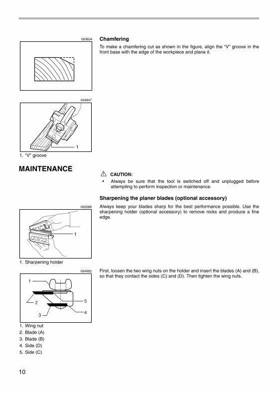
ChamferingTo make a chamfering cut as shown in the figure, align the “V” groove in thefront base with the edge of the workpiece and plane it.
MAINTENANCECAUTION:
• Always be sure that the tool is switched off and unplugged beforeattempting to perform inspection or maintenance.
Sharpening the planer blades (optional accessory)
Always keep your blades sharp for the best performance possible. Use thesharpening holder (optional accessory) to remove nicks and produce a fineedge.
First, loosen the two wing nuts on the holder and insert the blades (A) and (B),so that they contact the sides (C) and (D). Then tighten the wing nuts.
1. “V” groove
003634
1
004847
1. Sharpening holder
1
002588
1. Wing nut2. Blade (A)3. Blade (B)4. Side (D)5. Side (C)
1
2
3
5
4
004952

11
Immerse the dressing stone in water for 2 or 3 minutes before sharpening.Hold the holder so that the both blades contact the dressing stone for simulta-neous sharpening at the same angle.
Replacing carbon brushesRemove and check the carbon brushes regularly. Replace when they weardown to the limit mark. Keep the carbon brushes clean and free to slip in theholders. Both carbon brushes should be replaced at the same time. Use onlyidentical carbon brushes.
Use a screwdriver to remove the chip cover.
Use a screwdriver to remove the brush holder caps. Take out the worn carbonbrushes, insert the new ones and secure the brush holder caps.To maintain product SAFETY and RELIABILITY, repairs, any other mainte-nance or adjustment should be performed by Makita Authorized Service Cent-ers, always using Makita replacement parts.
004953
1. Limit mark
1
001145
1. Chip cover2. Screwdriver
1
2
004848
1. Brush holder cap2. Screwdriver
1 2
004849

Makita Corporation
884522A6