MSP430 Programming - Texas...
22
MSP430 Programming Introduction If you’ve programmed most any mainstream microcontroller, this module shouldn’t be too much of a surprise. What may surprise you is just how little power the MSP430 can draw when the programmer makes some informed decisions. Most microcontrollers operate in a real-time environment and respond to either interrupts or timers. The MSP430 is ideally suited to just this programming model. It can wake quickly, compute quickly and sleep deeply to save power and has a wide selection of highly capable and low power peripherals. Learning Objectives • MSP430 Products • Power Efficient Applications • Operating Modes • Clock Management • Peripherals • Timer • Coding Tips Low Power RF Solutions - MSP430 Programming 3 - 1
Transcript of MSP430 Programming - Texas...

MSP430 Programming
Introduction If you’ve programmed most any mainstream microcontroller, this module shouldn’t be too much of a surprise. What may surprise you is just how little power the MSP430 can draw when the programmer makes some informed decisions. Most microcontrollers operate in a real-time environment and respond to either interrupts or timers. The MSP430 is ideally suited to just this programming model. It can wake quickly, compute quickly and sleep deeply to save power and has a wide selection of highly capable and low power peripherals.
Learning Objectives • MSP430 Products
• Power Efficient Applications
• Operating Modes
• Clock Management
• Peripherals
• Timer
• Coding Tips
Low Power RF Solutions - MSP430 Programming 3 - 1

Module Topics
*** always wear sunscreen ***
3 - 2 Low Power RF Solutions - MSP430 Programming

Module Topics
Module Topics MSP430 Programming.............................................................................................................................. 3-1
Module Topics......................................................................................................................................... 3-3 MSP430 Products and Architecture........................................................................................................ 3-5 Power Efficient Applications and Power Modes..................................................................................... 3-6 Clock Management ................................................................................................................................. 3-7 Hints and Tips......................................................................................................................................... 3-8 Timers ....................................................................................................................................................3-11 Summary ................................................................................................................................................3-13 Lab3 – MSP430 Programming ..............................................................................................................3-15
Description: .......................................................................................................................................3-15 Hardware list: ....................................................................................................................................3-16 Software list:......................................................................................................................................3-16 Procedure...........................................................................................................................................3-17
Low Power RF Solutions - MSP430 Programming 3 - 3

Module Topics
*** I’ve seen an MSP430 run on a couple of grapes ***
3 - 4 Low Power RF Solutions - MSP430 Programming
MSP430 Products and Architecture
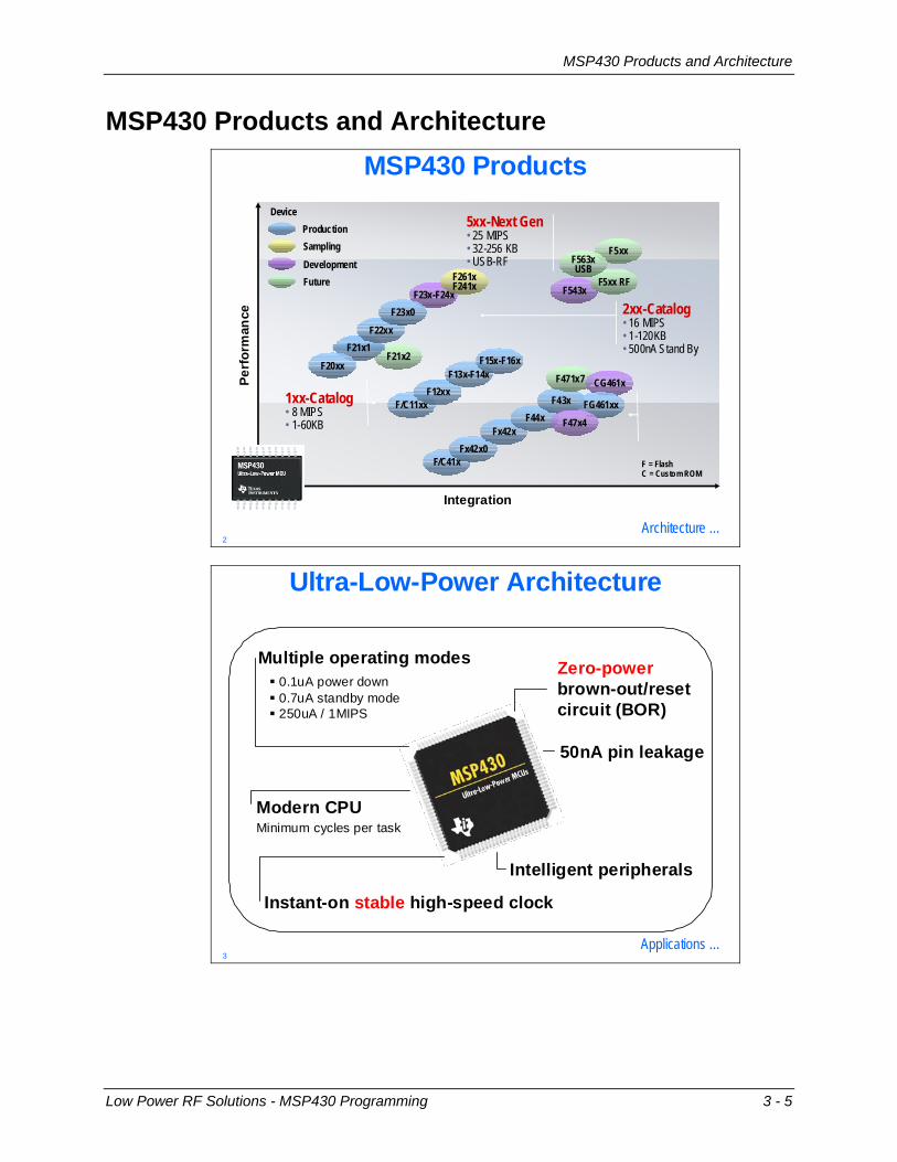
MSP430 Products and Architecture MSP430 Products
Architecture …
Perf
orm
ance
Integration
FutureDevelopmentSamplingProduction
Device5xx-Next Gen
2xx-Catalog
• 25 MIPS• 32-256 KB • USB-RF
• 16 MIPS• 1-120KB• 500nA Stand By
1xx-Catalog• 8 MIPS• 1-60KB
F5xx
F = FlashC = Custom ROM
F543xF5xx RF
F563xUSB
F23x-F24xF261xF241x
F/C11xxF12xx
F13x-F14xF15x-F16x
F/C41xFx42x0
Fx42xF44x
F43x
F471x7 CG461x
FG461xxF47x4
F21x2F21x1
F20xx
F22xxF23x0
2
Ultra-Low-Power Architecture
Modern CPUMinimum cycles per task
Multiple operating modes
Instant-on stable
Zero-power
high-speed clock
brown-out/resetcircuit (BOR)
Intelligent peripherals
50nA pin leakage
0.1uA power down0.7uA standby mode250uA / 1MIPS
Applications …3
Low Power RF Solutions - MSP430 Programming 3 - 5

Power Efficient Applications and Power Modes
Power Efficient Applications and Power Modes Design Power-Efficient Applications
Power-efficient MSP430 apps:Minimize the instantaneous current drawMaximize the time spent in low-power modes
The MSP430 is inherently low-power, but your design has a big impact on power efficiencyProper low-power design techniques make the difference
250uA
1uA
32768
DCOMCLKCPU and peripherals
ACLKlow-power peripherals
MSP430 Always-on
On demand
Operating modes …4
OffAll
Clocks Off0.1uA
OffAll
Clocks Off
Stand-byDCO off
ACLK on
0.1uA
1.0uA
Stand-byDCO offACLK on
1.0uA
LPM3RTC functionLCD driverRAM/SFR retained
CPU OffDCO onACLK on45-65uA
CPU OffDCO onACLK on45-65uA
Operating Modes
RAM/SFR retained
ActiveDCO onACLK on
LPM0 LPM4
300-500uA
ActiveDCO on
ACLK on300-500uA
<1-6us
<6us
Specific values vary by device
Clock Management …5
3 - 6 Low Power RF Solutions - MSP430 Programming

Clock Management
Clock Management Clock Management: 1xx, 2xx, 4xx
MCLK
LFXT1CLK
DCOCLK
CPUOFF
ACLK
SMCLK
SCG1
DCO
SCG0
OSCOFF
LFXT1 Oscillator
LF XT12pF12pF
VCC
Digitally ControlledOscillator
Instant on clock …6
Interrupt
DCO
Instant-On Clock
Near instant response to events, even from sleep modesAs a result, MSP430 can spend more time asleep
Operating modes …7
Low Power RF Solutions - MSP430 Programming 3 - 7

Hints and Tips
Hints and Tips Using MSP430 Operating Modes
Maximize time spent in low-power modesSet up interrupt handling and then go to sleep
Use ACLK for peripheralsAllows use of LPM3 instead of LPM0
Only activate peripherals while used, disable when finished
Effects of temperature …8
Effects of Vcc / MCLK / Temperature
Power draw increases with…VccCPU clock speed (MCLK)Temperature
Slowing MCLK reduces instantaneous power, but usually increases active duty cycle
Power savings nullified – best to use default MCLK (or increase it if required for application performance)
Unused I/Os …9
3 - 8 Low Power RF Solutions - MSP430 Programming
Hints and Tips
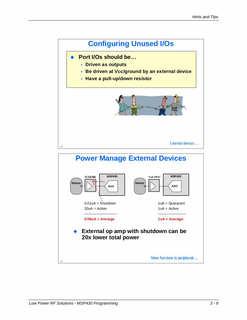
Configuring Unused I/Os
Port I/Os should be…Driven as outputsBe driven at Vcc/ground by an external deviceHave a pull-up/down resistor
External devices …10
Power Manage External Devices
External op amp with shutdown can be 20x lower total power
MSP430MSP430
Sensor
TLV2760SD
ADC
Px.x Sensor
"1uA OPA"
ADC
0.01uA = Shutdown 20uA = Active---------------------------
1uA = Quiescent1uA = Active -----------------------
0.06uA = Average 1uA = Average
Move functions to peripherals …11
Low Power RF Solutions - MSP430 Programming 3 - 9

Hints and Tips
Move Functions to Peripherals
Peripherals use less current than CPUDelegating to them allows CPU to shut down, saving system power“Intelligent” peripherals are more capable, providing more opportunity for CPU shutoffUse DMA for repetitive data handling rather than CPU load/store
Reduce Cycles …12
Reduce CyclesCPU active time is a direct function of how many cycles need to be executedReducing cycles is key to maximizing the use of low-power modesMany ways to do this, but an important one is interrupt-driven coding
100% CPU Load
UARTRXTX9600 baud
// Polling UART ReceiveFor(;;)while (!(IFG2&URXIFG0));TXBUF0 = RXBUF0;
// Polling UART ReceiveFor(;;)while (!(IFG2&URXIFG0));TXBUF0 = RXBUF0;
// UART Receive Interrupt#pragma vector=UART_VECTOR__interrupt void rx (void)TXBUF0 = RXBUF0;
0.1% CPU Load
// UART Receive Interrupt#pragma vector=UART_VECTOR__interrupt void rx (void)TXBUF0 = RXBUF0;
Timer_A …13
3 - 10 Low Power RF Solutions - MSP430 Programming
Timers
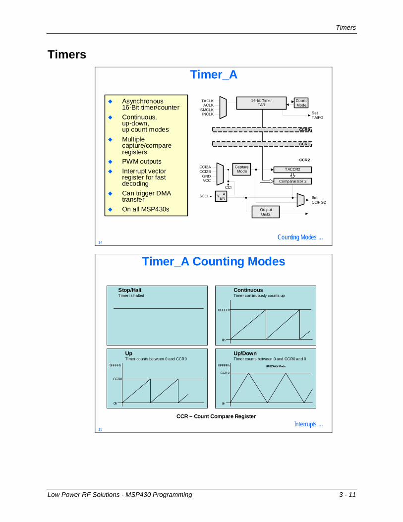
Timers Timer_A
Asynchronous16-Bit timer/counter Continuous,up-down,up count modesMultiple capture/compare registersPWM outputsInterrupt vectorregister for fastdecoding Can trigger DMA transferOn all MSP430s
Compararator 2CCI
CountMode
SetTAIFG
TACCR2
ACLKSMCLK
TACLK
INCLK
GNDVCC
CCI2ACCI2B
SetCCIFG2
OutputUnit2
CCR0
SCCI Y AEN
CCR1
CCR2
CaptureMode
16-bit TimerTAR
Counting Modes …14
Timer_A Counting Modes
0FFFFh
0h
CCR0
Stop/Halt Timer is halted
UpTimer counts between 0 and CCR0
0FFFFh
0h
Continuous Timer continuously counts up
0FFFFh
0h
CCR 0
UP/DOWN Mode
Up/Down Timer counts between 0 and CCR0 and 0
CCR – Count Compare RegisterInterrupts …
15
Low Power RF Solutions - MSP430 Programming 3 - 11

Timers
Timer_A Interrupts
TACCR1 CCIFG
TACCR2 CCIFG
TAIFG
TIMERA1_VECTORTAIV
TACCR1, 2 and TA interrupt flags are prioritized and combined using the Timer_A Interrupt Vector Register (TAIV) into anotherinterrupt vector
TACCR0 CCIFG TIMERA0_VECTOR
The Timer_A Capture/Comparison Register 0 Interrupt Flag (TACCR0) generates a single interrupt vector:
Your code must contain a handler to determine which Timer_A1 interrupt triggered
No handler required
TAIV …16
TAIV Handler Example
#pragma vector = TIMERA1_VECTOR__interrupt void TIMERA1_ISR(void)switch(__even_in_range(TAIV,10))case 2 : // TACCR1 CCIFGP1OUT ^= 0x04; break;
case 4 : // TACCR2 CCIFGP1OUT ^= 0x02; break;
case 10 : // TAIFGP1OUT ^= 0x01; break;
#pragma vector = TIMERA1_VECTOR__interrupt void TIMERA1_ISR(void)switch(case 2 : // TACCR1 CCIFGP1OUT ^= 0x04; break;
case 4 : // TACCR2 CCIFGP1OUT ^= 0x02; break;
case 10 : // TAIFGP1OUT ^= 0x01; break;
Source TAIV Contents
__even_in_range(TAIV,10))
No interrupt pending 0TACCR1 CCIFGTACCR2 CCIFG ReservedReserved TAIFGReservedReserved
02h04h06h08h0Ah0Ch0Eh
0TAIV
15xxxx00000000000
0
C Coding Tips …17
3 - 12 Low Power RF Solutions - MSP430 Programming

Timers
Summary
C Coding TipsUse local variable as much as possible. Local variables use CPU registers where global variables use RAM.Use bit mask instead of bit fields for unsigned int and unsigned char.Use unsigned data types where possibleUse pointers to access structures and unionsUse “static const” class to avoid run-time copying of structures, unions, and arrays.Avoid moduloCount down “for” loopsGet to know your C code and its disassembly
Summary …18
SummaryProper system design is necessary for the best low-power performanceMaximize power efficiency by minimizing program duty cycleMake good use of all power modesReduce program cycles
Lab Time …19
Low Power RF Solutions - MSP430 Programming 3 - 13

Timers
*** this page isn’t really blank, you know ***
3 - 14 Low Power RF Solutions - MSP430 Programming
Lab3 – MSP430 Programming
Lab3 – MSP430 Programming
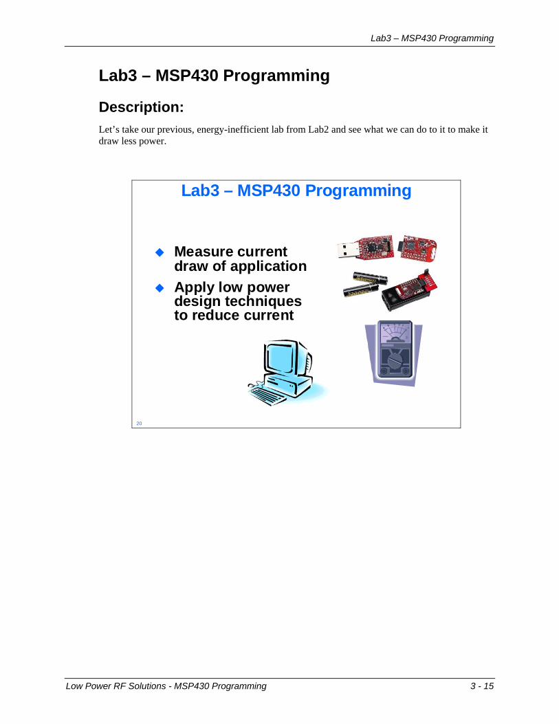
Description: Let’s take our previous, energy-inefficient lab from Lab2 and see what we can do to it to make it draw less power.
Lab3 – MSP430 Programming
Measure current draw of applicationApply low power design techniques to reduce current
20
Low Power RF Solutions - MSP430 Programming 3 - 15

Lab3 – MSP430 Programming
Hardware list:
3 eZ430-RF2500 Target Boards 2 Battery Modules 4 AAA Batteries 1 eZ430-RF2500 Emulator Board 1 USB Extender Cable 1 Volt-Ohm-Milliampmeter 1 set of Banana plug to Mini-Clip test leads
Software list:
IAR Embedded Workbench for MSP430 version 4.11D (You will find shortcuts for the above application on the desktop)
3 - 16 Low Power RF Solutions - MSP430 Programming

Lab3 – MSP430 Programming
Procedure
Measure the Current
1. Baseline Reconnect the Power jumper on the battery module (the one we used at the end of the last lab). The LEDs on the attached target board should be flashing again. Take your Volt-Ohm-Milliameter (VOM) and connect the black banana plug to the COM input and the red banana plug to the VΩmA input. Remove the Power jumper from the battery module and put it where you’ll be able to find it again. On the VOM, select 20m under DCA. Connect the black mini-clip at the other end of the test lead to the battery module pin nearest the batteries. Connect the red mini-clip to the pin furthest away from the batteries. If you manage to get this backwards, the current will merely be negative. The eZ430-RF2500 target board doesn’t just have a MSP430 on it. When connected to the battery, the CC2500 is also powered. When powered up, the CC2500 goes into an idle state and draws about 1.5mA. It is possible to send the device into a sleep state in which it would draw nanoamps, but that would require us to add most of the SimpliciTI software to the project. In the interest of doing things simply, we’ll just subtract 1.5mA from our measurements to get the CPU current. My measurement was about 6.5mA – 1.5MA = 5mA. Fill in yours below. If my memory from my 9th grade electronics class is still accurate, Power (P) = Voltage (E) x Current (I) The Voltage is 2.9V (measure it yourself across the two batteries), so I calculate 14.5mW. You will be awarded demerits for writing down any values below tenths of a mW.
Measured mA – 1.5mA Calculated Power (mW) S/W loop with LEDs S/W loop w/o LEDs LPM0 w/o LEDs LPM3 w/o LEDs
Table 1 Some of this current is for the LEDs. Let’s get rid of that in the next steps.
Low Power RF Solutions - MSP430 Programming 3 - 17

Lab3 – MSP430 Programming
2. Lose those LEDs With the LEDs blinking, a substantial amount of the current draw could be from them alone. Let’s turn them off and see what the MCU draws by itself. Start IAR Embedded Workbench and open the existing workspace Lab3.eww in C:\Texas Instruments\SimpliciTI-1.0.6\Projects\Examples\ Peer applications\eZ430RF\Lab3. This is simply the project from Lab2 copied over into a new folder. Open main.c for editing. Comment out the three LED control statements and replace each of them with BSP_TURN_OFF_LED2(); as shown below. This will execute exactly the same number of instructions, but will not light the LEDs.
3. Build/Load and Measure Build and load the program by clicking the Debug button . When the download is complete, click the Stop Debugging button . Remove the target board, attach it to the battery module and measure the current. I got 4.3mA – 1.5mA = 2.8mA and calculated 8.1mW. Enter your values into the table in step 1.
4. Using a Timer Using CPU cycles to provide a delay time is not only wasteful of CPU cycles and power, it’s the wrong way to program an MSP430. As an example of how a programmer can use the peripherals to save power, we’ll use a timer to provide us with a delay. Every MSP430 has a Timer_A peripheral, so let’s use that one. I didn’t write the code that follows from scratch; I stole it from slac123, which is a downloadable set of code example for the MSP430F2274 and others. www.ti.com/msp430 is where you can find a ton of example code. Save yourself some time and check it out before you start coding your project at home. I dropped the important code pieces into a file named Lab3 Code.txt so you wouldn’t have to type them in. Click the Open button on the menu, navigate to: C:\Texas Instruments\SimpliciTI-1.0.6\Projects\Examples\Peer applications\ eZ430RF\Lab3, select Lab3 Code.txt and click Open to open it for editing.
3 - 18 Low Power RF Solutions - MSP430 Programming

Lab3 – MSP430 Programming
5. LPM0 and Cut/Paste Add LPM0; statements before and after the LED control statements inside the while() loop, like below: Cut/paste the top portion of the code from Lab3 Code.txt into main.c just above the while(1) statement. Cut/paste the middle portion from Lab3 Code.txt into main.c at the end of the file, like below:
Want to find out more about programming MSP430 timers? Search the TI website for the MSP430x2xx User’s Guide.
Low Power RF Solutions - MSP430 Programming 3 - 19

Lab3 – MSP430 Programming
Re-enable the LEDs The code won’t be very interesting if we can’t see it work. Comment/un-comment the LED control statements like below:
6. Build/Load/Run Take a target board and carefully insert it into the emulator, then build the project. Make sure that it builds without error, and then click the Go button. The LEDs should be blinking quite a bit faster than before, but it will do for the purposes of this exercise. Warning: Code Explanation Ahead The code that we added controls Timer_A and its interrupt response. In the code right above while(): TACCTL0 0 = CCIE; enables Timer_A to generate an interrupt TACCR0 = 65535; loads the maximum possible value into the 16-bit count register TACTL = TASSEL_2 +MC_2; selects MCLK as the timer clock and continuous as the count mode _EINT(); enables global interrupts The code we added at the bottom of main.c is the Timer_A interrupt service routine. #pragma vector=TIMERA0_VECTOR places the ISR correctly in memory __interrupt void Timer_A(void) tells the compiler this is an ISR TACCR0 += 65535; adds offset to count register LPM0_EXIT; returns to low power mode By the way, LPM0; drops the MSP430 into this operating mode with the DCO on.
3 - 20 Low Power RF Solutions - MSP430 Programming

Lab3 – MSP430 Programming
7. Turn off the LEDs Click the Stop Debugging button and un-do the LED code changes we just made:
Build and load the project to the target, then click the Stop Debugging button.
8. Measure Current Connect the target board to the battery module and measure the current. I got 2.1mA – 1.5mA = 0.6mA or 1.7mW. Write your values into the table.
9. LPM3 In the existing code, we’re running the MSP430 on the DCO at 8MHz. For this code, that’s overkill. We can easily run it on the VLO (Very Low frequency oscillator) that is internal to the MSP430. But if we simply change out LPM0; statements to LPM3; the code simply won’t work; the VLO needs to be setup and the timer needs to be changed to clock on the VLO. Start out by changing both LPM0; statements to LPM3; .
10. Clock setup Code Delete the four lines of code just above the while() statement and replace them with the six lines of code at the bottom of Lab3 Code.txt . Add #include “VLO_Library.h” as the third include file at the top of main.c. Add VLO_Library.s43 from C:\Texas Instruments\SimpliciTI-1.0.6\Projects\ Examples\Peer applications\eZ430RF\Lab3 to the Source group in the Workspace window. Delete TACCR0 += 65535; from the ISR at the bottom of main.c. Finally, add unsigned int dco_delta; right below the line defining i.
Low Power RF Solutions - MSP430 Programming 3 - 21

Lab3 – MSP430 Programming
11. Build/Load/Run Before testing the code, swap the LED comments back so you can see the code operating. Build/load/run. The numbers I selected for the timer should look about like what we had before. Click the Stop Debugging button, swap the LED comments back so the LEDs stay off and Build/Load the project. Click the Stop Debugging button.
12. Measure Connect this target board to the battery module and measure the current. I got 1.7mA – 1.5mA = 0.2mA or 0.6mW. Write your values into the table.
13. Shut Down Shut the VOM off, wrap the test leads around it and give it to your instructor; we won’t need it again in this workshop. Shut down IAR Embedded Workbench, disconnect the eZ430-RF2500 hardware and extender cable and put them aside. Make sure to get that jumper and place it on one of the battery pins for safekeeping.
You’re done
3 - 22 Low Power RF Solutions - MSP430 Programming