MSC.Software Simulation Solutions Overview for...
61
Presented By: Daniele Catelani – MSC.Software June 13, 2012 MSC.Software Simulation Solutions Overview for Aerospace
Transcript of MSC.Software Simulation Solutions Overview for...
Presented By: Daniele Catelani – MSC.Software
June 13, 2012
MSC.Software Simulation Solutions
Overview for Aerospace

MSC Software Confidential 6/13/20121
1999Addition of
Nonlinear
Simulation
1963MacNeal-
Schwendler
Corporation
founded
1965MSC & NASA:
Nastran is born
1973MSC goes
Global
2009STG Acquires
MSC
2002Addition of
Multibody
Simulation
2010Multidiscipline
Innovation in
MSC Nastran
Solver
1994Addition of
Pre/Post
Processing
1969First MSC
Nastran
Installation
2011Addition of
CFD and
Acoustics
49 years in Simulation for Engineering

MSC Software Confidential
MSC Software: A Global Team
Corporate talent assets
1200 people WW
Corporate Headquarters
Pune
Munich Tokyo Beijing Paris
Ann Arbor
6/13/2012 2

MSC Software Confidential
MSC Software: The Italian Team
• Italy talent assets
• 40 people + external
consultants / partners
• Offices Location
• Roma
• Torino
• Udine
• Genova
MSC Software Confidential
MSC.Software Customers
Trusted by over 10,000 Manufacturers
Worldwide

MSC Software Confidential
MSC Simulation PortfolioBuild, Manage, Solve
56/13/2012
Broadest Range of CAE
Solutions for Engineers
Simulate range of structural and
multiphysics problems
Create, build and simulate
mechanical systems and controls
performance
Model and simulate acoustics
and CFD problems to optimize
designs
Study durability and design
life predictions to improve quality
Manage simulation process and
track pedigree of all data

MSC Software Confidential
Structures
& Multiphysics

MSC Software Confidential
MSC Software Simulation SolutionsStructural and Multiphysics Simulations
Simulate Advanced Linear,
Nonlinear, and Multiphysics
• Linear statics and dynamics
• Frequency domain analyses
• Nonlinear analysis capabilities through supported Marc solver
• Thermal
• Composites
• Optimization
• Superelement and parallelization
• Standard, scalable solution with widely recognized input file format
• Benefits
• Fewer physical prototypes
• Optimized Designs
• Faster results with better reliability

MSC Software Confidential
MSC NastranIntegrated CAE Solver
8
Linear statics•Connectors
•Contact
•Assemblies
Linear Dynamics•Eigen value•Real and complex
•Frequency response
Acoustics•Interior
•Exterior
•Structural-acoustic coupling
Optimization•Shape
•Size
•Topology
•Topometry
•Topography
•NonlinearNonlinear
Structures•Materials
•Large strain/deformation
•Contact
•Failure
•Composites
•Rotor dynamics
Thermal•Conduction
•Convection
•Radiation
•Advection
Coupling•Thermal-structural
•Structural-acoustic
•Fluid-structural
Nonlinear Dynamics•Explicit
•Nonlinear materials
•Contact
•Large deformation
Chaining•Thermal-structural
•Perturbation
•Implicit-explicit-implicit
•Explicit-explicit
High Performance•Shared memory parallel
•Distributed memory
parallel
•Massively parallel
•Iterative solvers
MSC Software Confidential
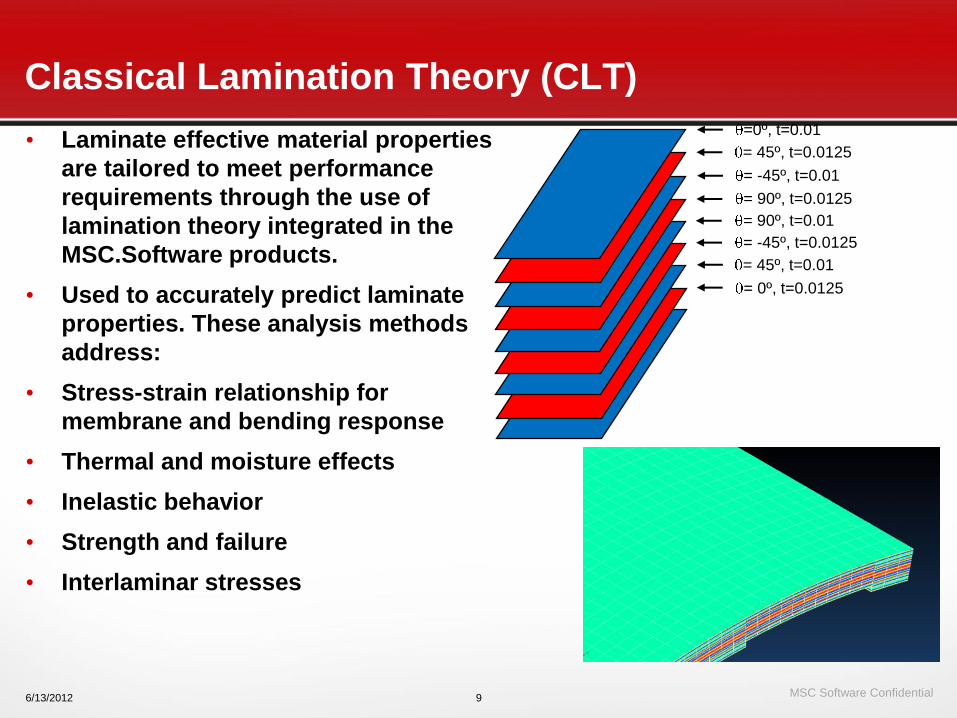
• Laminate effective material properties
are tailored to meet performance
requirements through the use of
lamination theory integrated in the
MSC.Software products.
• Used to accurately predict laminate
properties. These analysis methods
address:
• Stress-strain relationship for
membrane and bending response
• Thermal and moisture effects
• Inelastic behavior
• Strength and failure
• Interlaminar stresses
6/13/2012 9
= 0º, t=0.0125
= 45º, t=0.01
= 90º, t=0.01
= -45º, t=0.01
=0º, t=0.01
= -45º, t=0.0125
= 90º, t=0.0125
= 45º, t=0.0125
Classical Lamination Theory (CLT)

MSC Software Confidential
• Evaluate the load redistribution in a composite structure as the
plies fail progressively
10
CZM
Delamination
PFA
• Simulate delamination growth from initial flaw
• Study crack propagation to design for fail-safe
structures
VCCT
Going Beyond First-Ply-Failure

MSC Software Confidential
• SOL 200 used extensively for
airframe sizing at Boeing,
Lockheed, Fairchild-Dornier
and others
• Recent Examples
– Boeing Sonic Cruiser
– Boeing 7E7
– Lockeed F-35
– FD 728/928 series regional
aircraft
• Typically Multi-disciplinary
– Statics
– Flutter
– Performance/Control
Effectiveness (Static
Aeroelasticity)
Sizing optimization in aerospace structuresAirframe Sizing
• References
– Reference 1: Lockheed-Martin– Integration of External Design Criteria with MSC.Nastran Structural
Analysis and Optimization. Paper No. 2001-15, MSC.Software 2002 Worldwide Aerospace and Technology howcase,D.K. Barker, J.C. Johnson, E.H. Johnson, D.P. Layfield
– Reference 2: Fairchild-Dornier– Multidisciplinary Design Optimization Of A Regional Aircraft Wing Box.
G. Schuhmacher, I. Murra, L. Wang, A. Laxander, O.J. O’Leary. 9th AIAA Symposium on Multidisciplinary Analysis and Optimization, September, 2002. Paper: AIAA 2002 5406
ObjectiveWeight Minimization
Design VariablesThicknesses, areas, offsetsCROD-sections properties and dimensions
Typical constraintsStress and force (DRESP1)Panel Buckling (DRESP1)Design criteria calculations (DRESP1 or DRESP3)Manufacturability criteria (DRESP2 or DRESP3)Flutter damping values (DRESP1)Performance rates and effectiveness - e.g. roll
rate and roll effectiveness (DRESP1 or DRESP2)
MSC Software Confidential
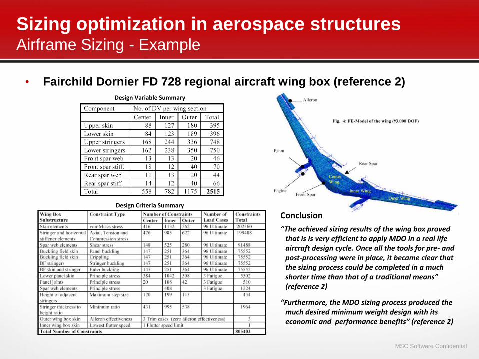
• Fairchild Dornier FD 728 regional aircraft wing box (reference 2)
Sizing optimization in aerospace structuresAirframe Sizing - Example
Design Variable Summary
Design Criteria Summary
Conclusion
“The achieved sizing results of the wing box proved that is is very efficient to apply MDO in a real life aircraft design cycle. Once all the tools for pre- and post-processing were in place, it became clear that the sizing process could be completed in a much shorter time than that of a traditional means” (reference 2)
“Furthermore, the MDO sizing process produced the much desired minimum weight design with its economic and performance benefits” (reference 2)

MSC Software Confidential
• The main objective is to minimize the compliance of the front
mount beam of the engine
The areas highlighted in blue (relative to the constraints regions) should not be touched by the process of topology optimization
DESIGN SPACE
14 loading conditions relative to different load combinations acting in the holes of the connection in case of the most critical maneuvers
XYZ Displacement constraints at 5 selected Grids:
- 6. < Δu > + 6.
Topology optimization - Aircraft Engine Mount
Problem definition
MSC Software Confidential
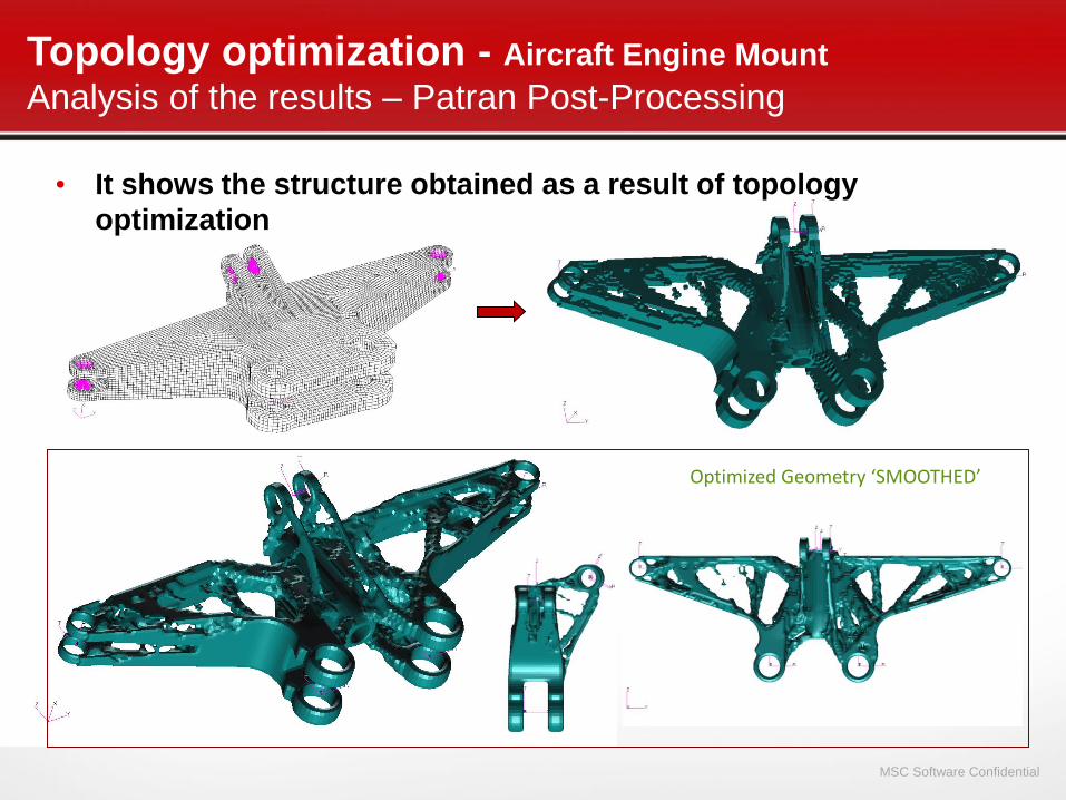
Optimized Geometry ‘SMOOTHED’
• It shows the structure obtained as a result of topology
optimization
Topology optimization - Aircraft Engine Mount
Analysis of the results – Patran Post-Processing
MSC Software Confidential
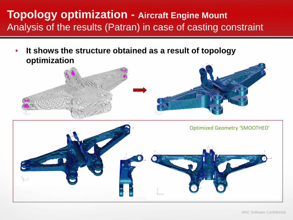
Optimized Geometry ‘SMOOTHED’
Topology optimization - Aircraft Engine Mount
Analysis of the results (Patran) in case of casting constraint
• It shows the structure obtained as a result of topology
optimization
MSC Software Confidential
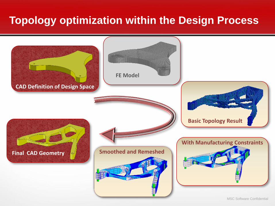
CAD Definition of Design Space
FE Model
Basic Topology Result
With Manufacturing Constraints
Smoothed and RemeshedFinal CAD Geometry
Topology optimization within the Design Process

MSC Software Confidential
Conventional Design
‒ Weight=11.39; F1 = 79.5Hz
Topograpy optimizationSpace Example
- 1 -
Objective: Max Freq
Constraint: none
F1=61.0 Hz
Wt = 10.91
13 cycles
Initial Design is Flat PanelR=90., Θ=28.6°, Z=30., t=.08, Wtinit=10.78, F1init=16.8Hz
- 2 -
Objective: Min Wt
Constraint: F1>35Hz
F1 = 36.0 Hz
Wt = 10.81
6 cycles

MSC Software Confidential Bolt Pre-Loading
Thermal-Structural
Coupling
Multiphysics – Fluid, Thermal, Structural, EM, EE
OpenFSI
Engine Bolts
Magnetostatic-
Structural
Fluid-Structure
MSC Software Confidential
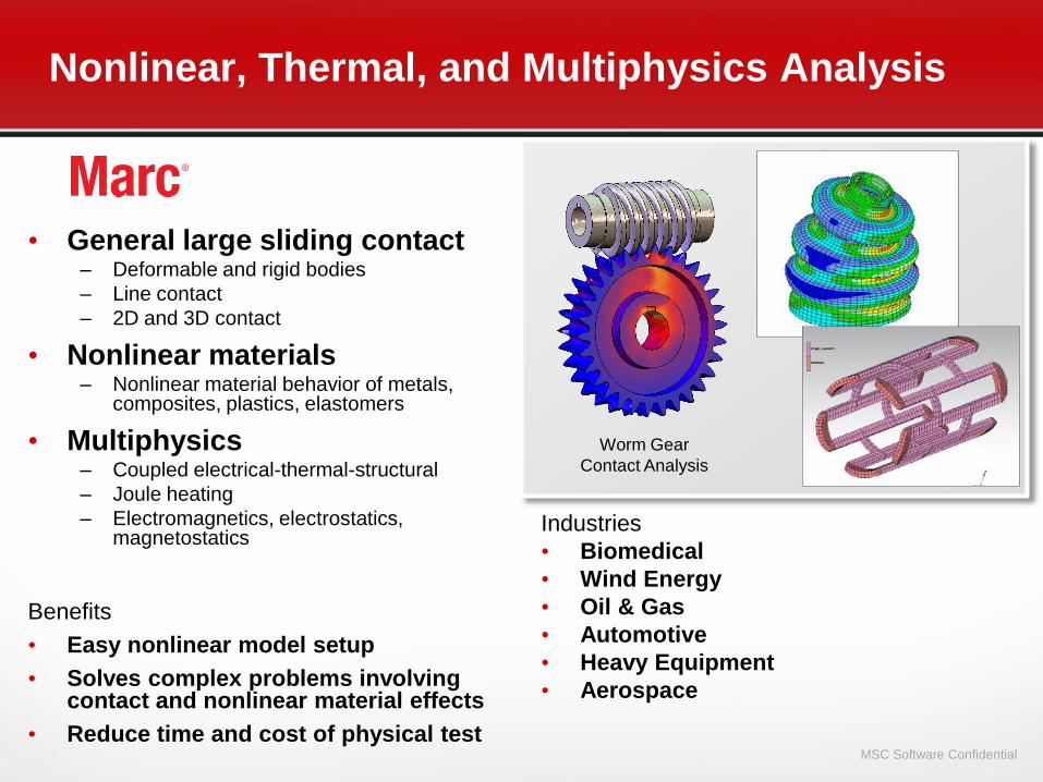
Nonlinear, Thermal, and Multiphysics Analysis
• General large sliding contact– Deformable and rigid bodies
– Line contact
– 2D and 3D contact
• Nonlinear materials– Nonlinear material behavior of metals,
composites, plastics, elastomers
• Multiphysics– Coupled electrical-thermal-structural
– Joule heating
– Electromagnetics, electrostatics, magnetostatics
Benefits
• Easy nonlinear model setup
• Solves complex problems involving contact and nonlinear material effects
• Reduce time and cost of physical test
Industries
• Biomedical
• Wind Energy
• Oil & Gas
• Automotive
• Heavy Equipment
• Aerospace
Worm Gear
Contact Analysis

MSC Software Confidential
Business: Mechanical junctions
Challenge: Simulate the clamping process of a stratified pipe in order to eliminate expensive experimental tests
Solution: MSC.MARC to simulate complete clamping process
MSC.CaseStudy: ITR - Parker
MSC Software Confidential
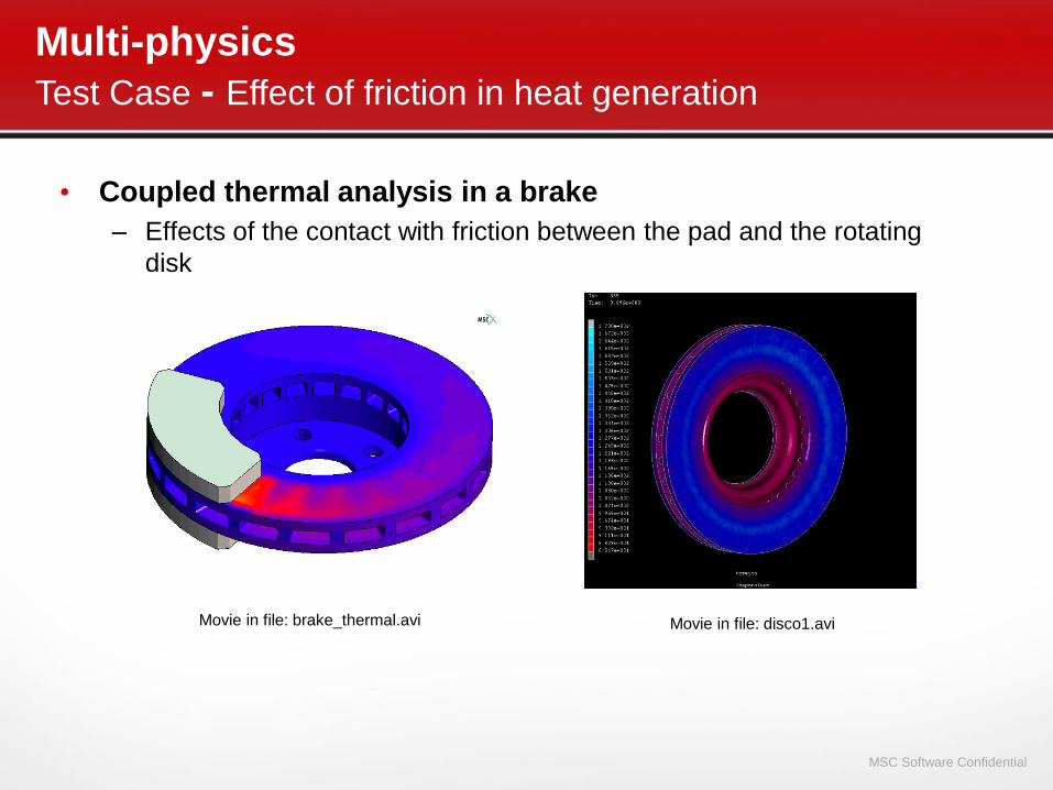
• Coupled thermal analysis in a brake
– Effects of the contact with friction between the pad and the rotating
disk
Multi-physics
Test Case - Effect of friction in heat generation
Movie in file: brake_thermal.avi Movie in file: disco1.avi

MSC Software Confidential
MultiphysicsElectromagnetic Analysis with Structural and Thermal Analysis
• Different coupling capabilities
• Electrostatic – Structural
• Magnetic – Structural• The Lorentz forces are calculated
and applied to the structure
Potential Magnetic Induction Temperature
• Magnetostatic – Thermal• The ferromagnetic lamination loss computation is done with magnetostatic
analysis and the heat generated due to these losses is used in the thermal
analysis
Magnetic Induction
Displacement

MSC Software Confidential
Systems
& Controls
MSC Software Confidential
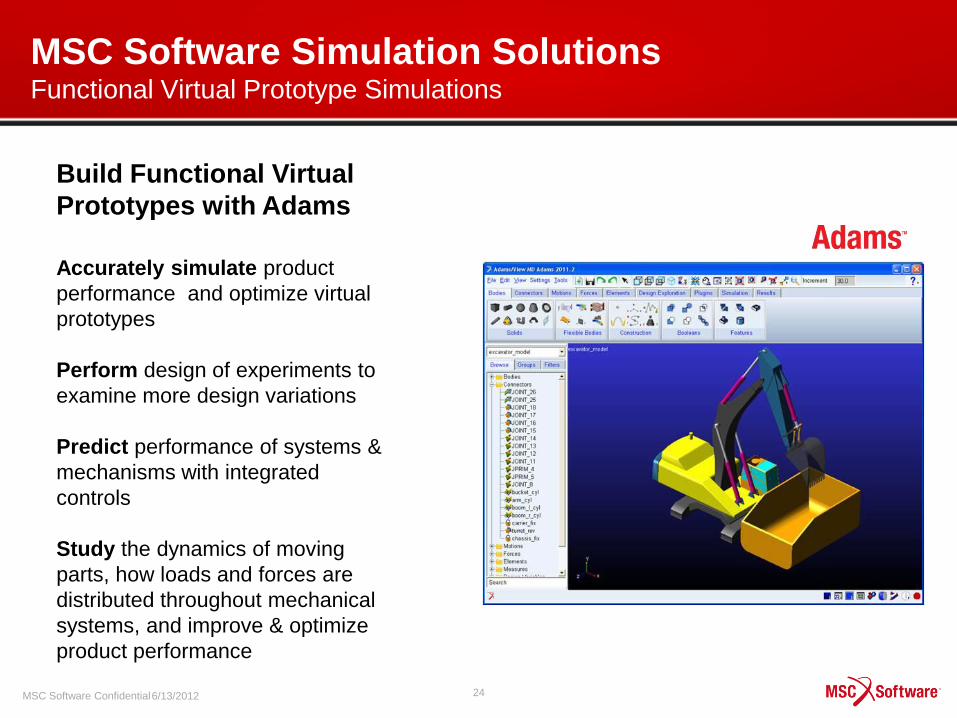
MSC Software Simulation SolutionsFunctional Virtual Prototype Simulations
246/13/2012
Accurately simulate product
performance and optimize virtual
prototypes
Perform design of experiments to
examine more design variations
Predict performance of systems &
mechanisms with integrated
controls
Study the dynamics of moving
parts, how loads and forces are
distributed throughout mechanical
systems, and improve & optimize
product performance
Build Functional Virtual
Prototypes with Adams

MSC Software Confidential
MSC Software Simulation Solutions Powerful Schematic-based Modeling Simulations
• Broad & Powerful Analysis Capabilities:
– Steady-state tool
– System stability via linear analyses tools
– Control system analyses
– DOE
– And More!
• CAE Tool Integration:
– Multibody dynamics via Adams
– DOE, optimization via Adams/Insight
– Flexible bodies via Nastran
– 3rd Party codes
256/13/2012
Quickly create high-fidelity system models with pre-built,
ready-to-use blocks in several Application Libraries

MSC Software Confidential
Case Study : Landing Gear Extraction/Retraction
26
• Integration MBS/Hydraulic system
• Modelization of actuators
• Performance evaluation

MSC Software Confidential
Example: Business Jet
27

MSC Software Confidential
Example: Business Jet
28
From take-off …
… To landing .
MSC Software Confidential
CFD
MSC Software Confidential
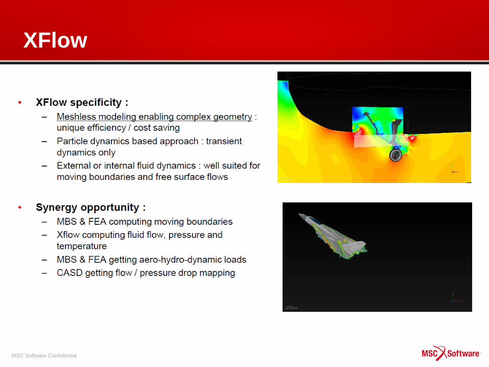
XFlow

MSC Software Confidential
Acoustic

MSC Software Confidential
Noise radiation by a large truck powertrain
FE Model
Noise maps
Contribution
analysis
ACTRAN

MSC Software Confidential
Multidiscipline
Simulation

MSC Software Confidential
Multidiscipline Parts & SystemsControls-MBD-FE Integration + CFD + Fatigue + …..
MBS + Fatigue
MBS + CFD + Fatigue
MBS + CFD + Fatigue + EE + Controls

MSC Software Confidential MSC Software Confidential 35
MB+FEMFlexible Body
Stress&Strains
Loads
CAD MB
Assembly
Modeling
Geometry
MB KIN & DYN
Kinematics
Clearance
Verification
Actuator
Hydraulics
Co-simulation
MB + Controls CFD+FEM+MB
Aerodynamic Loads
Full System
Multi Discipline Value
IPCommon Framework
Common Data Model
OP
MSC Software Confidential
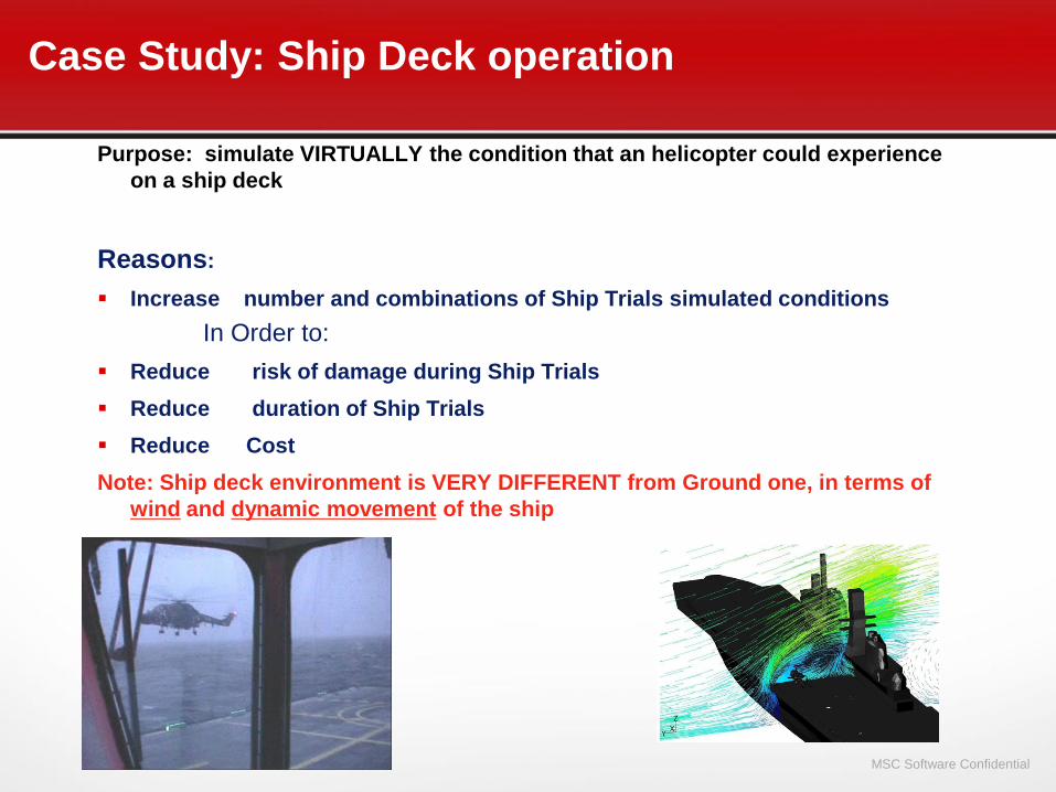
Purpose: simulate VIRTUALLY the condition that an helicopter could experience
on a ship deck
Reasons:
Increase number and combinations of Ship Trials simulated conditions
In Order to:
Reduce risk of damage during Ship Trials
Reduce duration of Ship Trials
Reduce Cost
Note: Ship deck environment is VERY DIFFERENT from Ground one, in terms of
wind and dynamic movement of the ship
Case Study: Ship Deck operation

MSC Software Confidential
Rotor Engage/Disengage: Blade Sailing
Aeroelastic Phenomenon:
• Involves Helicopter Rotor
• Characterized by Large Deflection and Loads
Risk: Tail Boom or Tunnel Strike
Occur: Low Rotational Speed during Rotor Engage and Disengage
Cause:
• Low Centrifugal Stiffening
• Non Uniform Aerodynamic Field (Beam Wind)
• Inertial Loads due to Ship Motions
• Flap Stop Impact
MSC Software Confidential
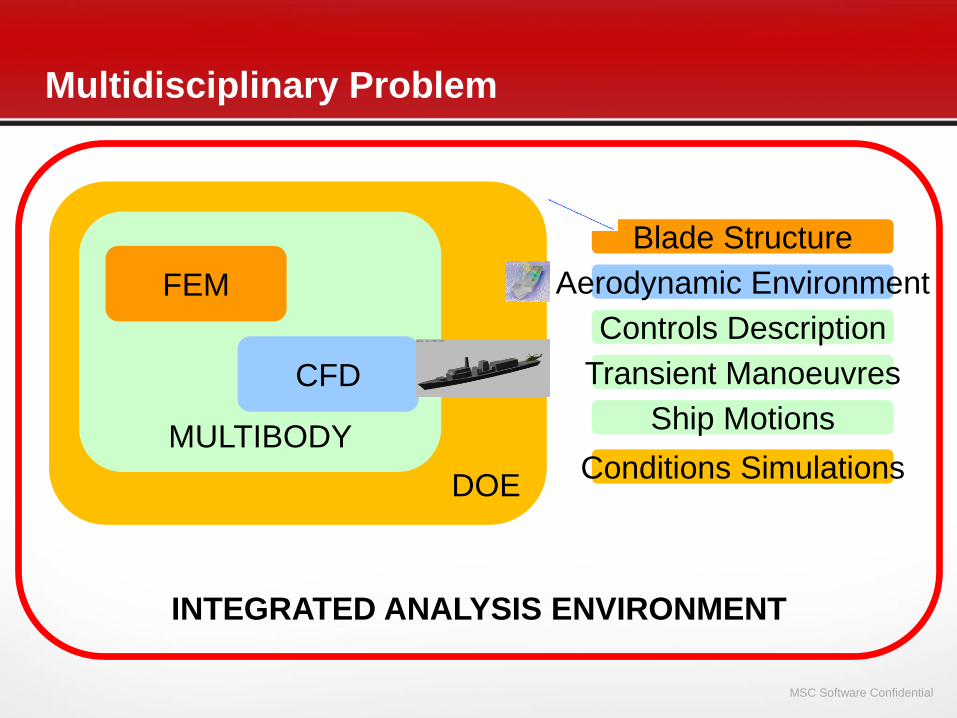
INTEGRATED ANALYSIS ENVIRONMENT
Multidisciplinary Problem
DOE
MULTIBODY
CFD
FEM
Blade Structure
Aerodynamic Environment
Controls Description
Ship Motions
Transient Manoeuvres
Conditions Simulations

MSC Software Confidential
Blade Structure: FEM / ADAMS Flex
MSC.Nastran Beams Model
Component Mode Synthesis
Inertia Structural Stiffness
Centrifugal
Stiffness
Elastic Deflection
Centre Mass

MSC Software Confidential
Aerodynamic Environment
Blade Aerodynamic Forces Complex Routine
•panel method
•steady/unsteady flow
•Inflow effect
•axial/hovering/forward flight
Rotor Aerodynamic Field
•CFD Based
•3D Interpolation
Wind Non Uniform Field

MSC Software Confidential
CFD Based Aerodynamic
CFD Analysis
Wind Components on Grid Points
3D Interpolation
Non Uniform Wind Velocity Field
Ship Motion
Rotor Motions
Wind Additional Components
Aerodynamic Forces

MSC Software Confidential
MultiBody
•Rotor Control Chain
•Blade Flap Stops
•Helicopter
Ship:
• Motions
• Helicopter Spot
Rotor Transient
Submodel

MSC Software Confidential
Doe Analysis
Customized Advanced Design of Experiment:•Single Blade Analysis
•Blade Starting Azimuth
•Wind Maps (CFD)
•Ship Motion Phases
Wind
1
n
Win
d
A1
A4

MSC Software Confidential 44
Helicopter Crash Analysis
• Testing area: Occupant Safety &
Crashworthiness.
• To guarantee FAA about helicopter standards
before it rolls out
• High cost and difficulties involved in real time
testing
• Accuracy of MSC.Dytran in predicting actual
crash events
• High speed computers available in the
market that solves a crash event within
hours/days
• Flexibility to setup the same model with
different crash scenarios (pitch, roll, yaw
angles and initial velocities)
==> Use MSC.ADAMS to initialize crash
events
4000 nodes
7000 elements

MSC Software Confidential 45
• Good Correlation with measured data
• Comparison with photographs and movies
• Accelerometers definition on physical and
virtual model
• Comparison btw numerical and experimental
plots
Helicopter Crash Analysis
MSC Software Confidential
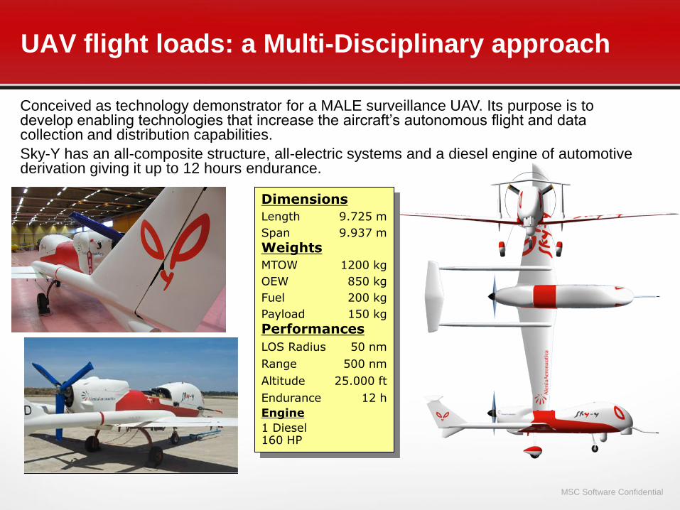
Dimensions
Length 9.725 m
Span 9.937 m
Weights
MTOW 1200 kg
OEW 850 kg
Fuel 200 kg
Payload 150 kg
Performances
LOS Radius 50 nm
Range 500 nm
Altitude 25.000 ft
Endurance 12 h
Engine
1 Diesel 160 HP
Conceived as technology demonstrator for a MALE surveillance UAV. Its purpose is to develop enabling technologies that increase the aircraft’s autonomous flight and data collection and distribution capabilities.
Sky-Y has an all-composite structure, all-electric systems and a diesel engine of automotive derivation giving it up to 12 hours endurance.
UAV flight loads: a Multi-Disciplinary approach
MSC Software Confidential
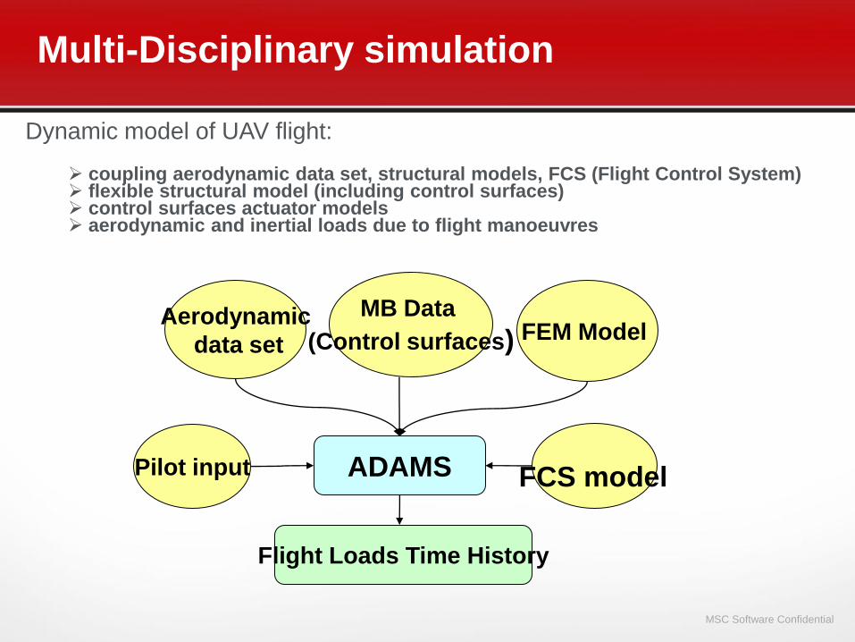
Multi-Disciplinary simulation
ADAMSPilot input FCS model
Aerodynamic
data setFEM Model
MB Data
(Control surfaces)
Flight Loads Time History
Dynamic model of UAV flight:
coupling aerodynamic data set, structural models, FCS (Flight Control System) flexible structural model (including control surfaces) control surfaces actuator models aerodynamic and inertial loads due to flight manoeuvres

MSC Software Confidential 48
Structure Technologies Domain
FEM
+
pressure
distribution
MB controlled
model
Matching
aerod/FEM
Action 1
Aero
data set
FEM
+
inertia
data
Create
modal data
Action 2
Loads on
structure
Manoeuvre
analysis
Action 4
Modal
data
Create MB
model
Action 3
MB
data:
control
surfaces
Actuators
loads and
position
Manoeuvre
response
data
Requirements
CAD & FEM &
MB & CFD
Pre
processing
Action 0 Generic
manoeuvre
response
Data
Extracting
specific
responses
Action 5
System Technologies Domain
Flight Tecnologies Domain
Pilot Input
MD process
FCS
model

MSC Software Confidential 49
Aerodynamic data set
The aerodynamic analysis is accomplished by using various analytical techniques such as Vortex Lattice or Euler formulation methods (CFD - Computational Fluid Dynamics).
These analytical techniques allow to generate an aerodynamic model starting from the
external shape of the air vehicle.
For a set of flight parameters ( , , , Mach), relevant aero-coefficients on predefined grids of the aerodynamic mesh are calculated.
These coefficients are assembled into the aerodynamic data set.
Macropanel
MacropanelPanels
MSC Software Confidential
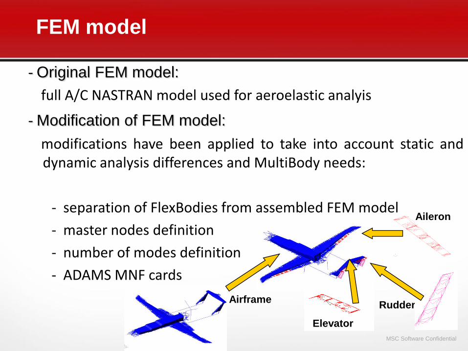
- Original FEM model:
full A/C NASTRAN model used for aeroelastic analyis
- Modification of FEM model:
modifications have been applied to take into account static anddynamic analysis differences and MultiBody needs:
- separation of FlexBodies from assembled FEM model
- master nodes definition
- number of modes definition
- ADAMS MNF cards
Airframe
Elevator
Rudder
FEM model
Aileron

MSC Software Confidential 51
Structural/Aerodynamic coupling
Aerodynamic model mesh Structural model (FEM)
Models coupling
CFD aero coefficent data set are transferred on the structural mesh
(not coincident with the aerodynamic one) using RBE3 element

MSC Software Confidential 52
Flight Control System (FCS) model
A Flight Control System has been developed, using General State Equation
(GSE) element (which allows discrete integration time step)
Input data time history of pilot commands (aileron, elevator, rudder, throttle)
are transferred through FCS model (Alenia Fortran routine – black box) and
GSE to control surfaces
Output are controlled surfaces rotations

MSC Software Confidential 53
The manoeuvre simulation is splitted in two phases:
1. Trim analysis defining the first instanct of the dynamic response. At the required speed, altitude, load factor (Nz), the equilibrium aircraft condition is found with angular acceleration = 0.
2. Dynamic analysis starting from trimmed position imposing pilot commands
Three kind of trimming have been considered:
pull out (Nz ≥ 1 ) steady turn (Nz > 1) inverted flight (Nz = -1)
Manoeuvres description

MSC Software Confidential 54
MD simulation - results
PULL OUT
Alpha

MSC Software Confidential 55
MD simulation - results
STEADY TURN

MSC Software Confidential
MSC Software Simulation SolutionsIntegrated Multidisciplinary Simulations
566/13/2012
Model and analyze structural,
thermal, motion, and systems
simulations in a single, fully
integrated user environment
Access native CAD features for
defeaturing and faster meshing &
pre-processing
Use a common data model across
discipline simulations for higher
accuracy and faster results
Automate standard and repeatable
simulations so simplify simulations
and reduce costs
Optimize Designs by Simulating
Multidisciplinary Problems
Structures ThermalMotion Crash/Explicit
Solution Extensions
Common
Data Model
MSC Software Confidential
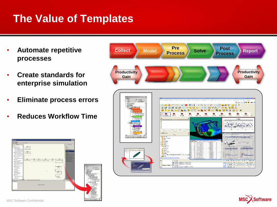
• Automate repetitive
processes
• Create standards for
enterprise simulation
• Eliminate process errors
• Reduces Workflow Time
The Value of Templates
SetupModel
CreateSupports
ApplyConstraints
ApplyLoads
ExportNastran
GRIDPairs
GenerateReport
SetupModel
CreateSupports
ApplyConstraints
ApplyLoads
ExportNastran
GRIDPairs
GenerateReport
Collect ModelPre
ProcessSolve
PostProcess
Report
Productivity
Gain
Productivity
Gain
MSC Software Confidential
Simulation Data
& Process
Management

MSC Software Confidential 6/13/2012
Innovation FrameworkManaging, Integrating, and Automating Simulation
Methods
• Manage diverse simulation content
– Models, files, inputs and outputs
– Instructions, Scripts, Macros, Templates
– Simulation Processes & CAE workflow
– Classify, Store, Protect, Distribute
Information
Motion Structures
CFD
Controls
Calculations
Instructions
Report
Report
Report
Processes
• Manage & automate simulation processes
– Manually repetitive tasks
– Standard procedures
– Multiple method execution sequences
– Schedule management on HPC
Methods
Collect Model Solve Report Pre
Process
Post
Process
Collect Model Solve Report Pre
Process
Post
Process
Collect Model Solve Report Pre
Process
Post
Process
Collect Model Solve Report Pre
Process
Post
Process
Collect Model Solve Report Pre
Process
Post
Process
Collect Model Solve Report Pre
Process
Post
Process
Collect Model Solve ReportPre
Process
Post
Process
Collect Model Solve ReportPre
Process
Post
ProcessCollect Model Solve ReportPre
Process
Post
Process
Collect Model Solve ReportPre
Process
Post
Process
• Document simulation audit trail
– Enable “SEARCH/FIND”
– Satisfy regulatory compliance
– Protect against liability

MSC Software Confidential 6/13/201260
www.mscsoftware.com