MSCom - Microelettrica · The Lite version (MSCom Lite) ... located on the World Wide Web Or,...
46
Doc. N° MO-0073-ING MSCom Rev. 4 Pag 1 di 46 RELAYS INTERFACING PROGRAM M M S S C C o o m m OPERATION MANUAL Copyright 1998 Microelettrica Scientifica
Transcript of MSCom - Microelettrica · The Lite version (MSCom Lite) ... located on the World Wide Web Or,...

Doc. N° MO-0073-ING
MSCom Rev. 4
Pag 1 di 46
RELAYS INTERFACING PROGRAM
MMSSCCoomm
OPERATION MANUAL
Copyright 1998 Microelettrica Scientifica

Doc. N° MO-0073-ING
MSCom Rev. 4
Pag 2 di 46
Copyright 1998 Microelettrica Scientifica
INDEX
1 Introduction to Microelettrica Scientifica and MSCom..................................................................4 1.1 Microelettrica Scientifica ..............................................................................................................................4 1.2 MSCom ...........................................................................................................................................................4
2 Technical Support ............................................................................................................................5 3 Hardware and Software Requirements ...........................................................................................6
3.1 Hardware Requirements ...............................................................................................................................6 3.2 Software Requirements ................................................................................................................................7
4 Getting Started .................................................................................................................................8 4.1 Getting Started...............................................................................................................................................8 4.2 Basics .............................................................................................................................................................9 4.3 File Save .......................................................................................................................................................10 4.4 Printing .........................................................................................................................................................10
5. General Overview and Features ...................................................................................................11 5.1 Relay Manager Window ..............................................................................................................................11 5.2 Menu bar.......................................................................................................................................................12
5.2.1 File menu ...............................................................................................................................................12 5.2.1.1 File | New .........................................................................................................................................12 5.2.1.2 File | Open........................................................................................................................................13 5.2.1.3 File | Close .......................................................................................................................................13 5.2.1.4 File | Save ........................................................................................................................................13 5.2.1.5 File | Save As... ................................................................................................................................13 5.2.1.6 File | Save Relays on network list ....................................................................................................13 5.2.1.7 File | Save Relays on network list As... ............................................................................................14 5.2.1.8 File | Save Active Relay ...................................................................................................................14 5.2.1.9 File | Save Active Relay As... ...........................................................................................................14 5.2.1.10 File | Save Connected/Opened Relays ..........................................................................................14 5.2.1.11 File | Save Connected/Opened Relays As.....................................................................................14 5.2.1.12 File | Print .......................................................................................................................................15 5.2.1.13 File | Printer Setup..........................................................................................................................15 5.2.1.14 File | Exit program ..........................................................................................................................15
5.2.2 Relay menu ............................................................................................................................................16 5.2.2.1 Relay | Connect New Relay .............................................................................................................16 5.2.2.2 Relay | Active relay connect .............................................................................................................16 5.2.2.3 Relay | Active relay disconnect ........................................................................................................16 5.2.2.4 Relay | Active relay close .................................................................................................................16 5.2.2.5 Relay | Open file relay ......................................................................................................................16 5.2.2.6 Relay | Add file relay ........................................................................................................................17 5.2.2.7 Relay | Delete file relay ....................................................................................................................18 5.2.2.8 Relay | Relay Manager.....................................................................................................................18
5.2.3 Measures menu.....................................................................................................................................18 5.2.3.1 Actual Measurements ......................................................................................................................18 5.2.3.2 Maximum values ..............................................................................................................................19 5.2.3.3 Measurements at the last trip...........................................................................................................20 5.2.3.4 Trip number ......................................................................................................................................21 5.2.3.5 Oscillographic data Recorder...........................................................................................................21
5.2.4 Settings menu .......................................................................................................................................25 5.2.4.1 Settings ............................................................................................................................................25 5.2.4.2 F->Relay – Output Relays................................................................................................................26
5.2.5 Status .....................................................................................................................................................27 5.2.6 Test Prg..................................................................................................................................................27 5.2.7 Tool.........................................................................................................................................................28
5.2.7.1 Polling...............................................................................................................................................28 5.2.7.2 Network Synchronization .................................................................................................................34 5.2.7.3 Remote Access ................................................................................................................................35

Doc. N° MO-0073-ING
MSCom Rev. 4
Pag 3 di 46
Copyright 1998 Microelettrica Scientifica
5.2.7.4 Circuit Breaker Control for MX.... .....................................................................................................39 5.2.8 Config Menu ..........................................................................................................................................40
5.2.8.1 Enable Read / Write .........................................................................................................................40 5.2.8.2 Disable Read/Write ..........................................................................................................................40 5.2.8.3 Change Password ............................................................................................................................40 5.2.8.4 Communication parameters .............................................................................................................41 5.2.8.5 Retry Connection..............................................................................................................................41
5.2.9 Help ........................................................................................................................................................42 5.3 Tool Bar ........................................................................................................................................................42 5.4 Status bar .....................................................................................................................................................43 5.5 New Tools.....................................................................................................................................................44
5.5.1 TCP/IP connection ................................................................................................................................44 5.5.2 Windows in Main Table ........................................................................................................................44
5.5.3 Relay Demo...............................................................................................................................................46
Doc. N° MO-0073-ING
MSCom Rev. 4
Pag 4 di 46
Copyright 1998 Microelettrica Scientifica
1 Introduction to Microelettrica Scientifica and MSCom
1.1 Microelettrica Scientifica Microelettrica Scientifica manufactures high-performance, reliable electric components and systems. Its name can
be found in all the most progressive sectors of industry.
Microelettrica Scientifica, particularly dedicated to research and innovation, has always played an active part in the
great technological changes of our time.
Founded in 1953, Microelettrica Scientifica has developed a wide range of products, divided into the following main
lines:
Electronic Relays for Transmission, Distribution and Machinery Protection
Series A: electronic analogic;
Series M: digital microprocessor.
Contactors for railway applications: these contactors have been expressly designed for application on
vehicles for electric traction. They are available as standard for applications from 1000 to 4000 V DC and can
also be used in AC circuits.
Contactors for industrial applications: these contactors find their specific application in the heavy industry,
where high performances and heavy duty are required as in control of cranes, rolling mills, mining equipment
and so on.
Resistors for industrial applications: due to their considerable electrical and mechanical characteristics, and
because of their modular construction, these types of resistors can be used in different applications: starting,
braking and slip control resistors, load resistors, star point earthing resistors, filter resistors, connection and
discharge resistors and current limiting resistors.
Resistors for railway applications: traction resistors have been supplied to railways and underground
systems for various application, like as braking and filter, and they have been designed and manufactured to
operate under the most severe conditions, including extreme environmental temperatures, shocks and
continuous vibration, polluted atmospheres, rain, snow, ice…
1.2 MSCom MSCom is a Windows-based communication program developed by Microelettrica Scientifica.
Microelettrica Scientifica is now delivering two versions of MSCom :
The Lite version (MSCom Lite) is totally free and it’s delivered with any Microelettrica Scientifica
microprocessor relay. It implements the ability to communicate with only one relay at the same time, the saving
of all relay data on the disk, the print of the data, but it doesn’t implement the ability to communicate via
modem, the graphical representation of the oscillographic data…
The Professional version (MSCom Pro) is a stand-alone product implementing the ability to communicate with
more then one relay at the same time (up to 5 relays), the saving of all data on the disk, the configuration of the

Doc. N° MO-0073-ING
MSCom Rev. 4
Pag 5 di 46
Copyright 1998 Microelettrica Scientifica
print out, the TCP/IP connection to the remote substations, a completely configurable polling and more
others…
The Professional version is a program to purchase separately.
MSCom program is suitable to read / modify settings and real measurements and all other stored values in any
Microelettrica Scientifica microprocessor relays.
MSCom is able to support all relays at the moment delivered by Microelettrica Scientifica.
MSCom Pro provides some additional features:
Connection up to 5 five devices at the same time.
Remote access via modem and phone line.
Printing: you can print the active relay data.
Saving: you can save in a file the active relay data, the opened file or the relays data available on the network
Measurements Polling: One or more variables per relay can be periodically read and displayed to the user. All
the data can also be recorded on the P.C.'s hard disk or directly sent to a printer.
Last Trips Polling: MSCom monitors the status of the relays trip counters. A new file containing the relay data at
the last trip is automatically generated whenever a trip counter is incremented by the relay.
MSGraphics : Graphical representation of the oscillographic data
Synchronization : the relays internal clocks can be synchronized through a periodic signal sent out automatically
by MSCom
2 Technical Support For technical support on the installation of MSCom, for questions about the program, to request program or
database upgrades, or to request the addition of new devices to the database, visit the MSCom Support Site
located on the World Wide Web http://www.microelettrica.com/Software
Or, contact:
Microelettrica Scientifica S.p.A. Via Alberelle 56/58
20089 Rozzano (MI)
Tel: +39-2-575731
Fax: +39-2-57510940
e-mail: [email protected]

Doc. N° MO-0073-ING
MSCom Rev. 4
Pag 6 di 46
Copyright 1998 Microelettrica Scientifica
3 Hardware and Software Requirements
3.1 Hardware Requirements PC Hardware Requirements
− PC with Pentium processor.
− At least 32 megabytes RAM.
− At least 100 megabytes free hard disk space.
− Colour monitor capable of VGA resolution ( al least 640x480 resolution with 256 colour)
− Keyboard and mouse.
Serial interface requirements The interface used for connection is RS-485 (half-duplex), which allows to connect in parallel up to 31 units.
The communication bus can be long up to and over 1000m if shielded twisted pairs of cable are used for
connection. Using a simple twisted pair the recommended length is reduced to 500 m. Using a fiber optic
transmission, up to 200 units can be connected on the same bus with distance up to 3 Km between units (glass
fibre optic).
For connection refer to attached diagram SCE1309.
An RS232/485 adapter is needed to use one of the serial ports available on the personal computer for the relay
management.
Microelettrica Scientifica's 232/485 converter automatically recognizes the data flow so no configuration is needed.
Doc. N° MO-0073-ING
MSCom Rev. 4
Pag 7 di 46
Copyright 1998 Microelettrica Scientifica
The use of a P.C. serial port fitted with a UART type 16550 is recommended; normally high speed serial ports
(baud rate over 9600bps) use that component.
If more than 2 serial ports are available on the P.C., please note that normally ports COM1 and COM3 share the
same interrupt (likewise for COM2 and COM4): therefore if for instance the mouse is connected to COM1, the relay
management bus shall not be connected to COM3 but to COM2 or COM4 only.
If a 485 interface card has to be installed in the computer, make sure it is configured so that transmission is
enabled by the RTS signal and that it does not clash with existing communication ports.
3.2 Software Requirements 3.2 Software Requirements
Microsoft Windows operating system: Windows 9x, ME, NT4 SP3, 2000.

Doc. N° MO-0073-ING
MSCom Rev. 4
Pag 8 di 46
Copyright 1998 Microelettrica Scientifica
4 Getting Started
4.1 Getting Started The MSCom main screen consists of different graphical items which allow to use all program features.
For the “Relay Manager Window” description please refer to § 5.1
For the “Menu bar” description please refer to § 5.2
For the “Tool Bar” description please refer to § 5.3
For the “Status Bar” description please refer to § 5.4
Doc. N° MO-0073-ING
MSCom Rev. 4
Pag 9 di 46
Copyright 1998 Microelettrica Scientifica
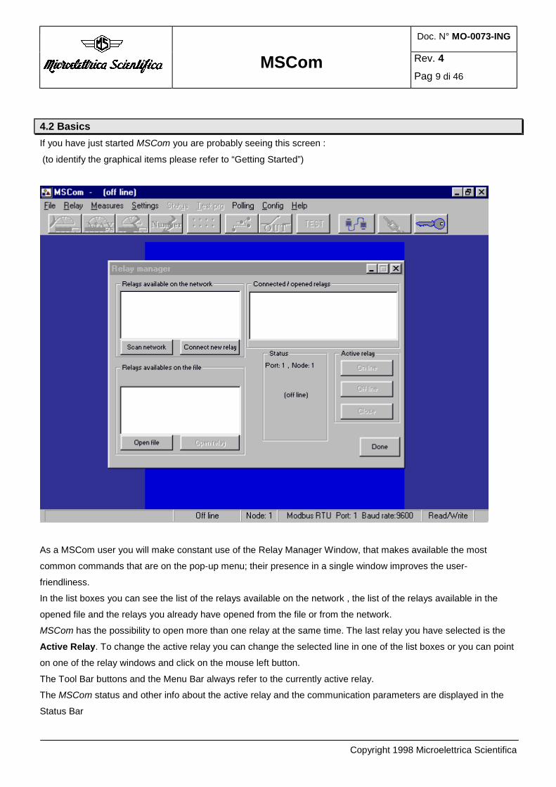
4.2 Basics
4.2 Basics If you have just started MSCom you are probably seeing this screen :
(to identify the graphical items please refer to “Getting Started”)
As a MSCom user you will make constant use of the Relay Manager Window, that makes available the most
common commands that are on the pop-up menu; their presence in a single window improves the user-
friendliness.
In the list boxes you can see the list of the relays available on the network , the list of the relays available in the
opened file and the relays you already have opened from the file or from the network.
MSCom has the possibility to open more than one relay at the same time. The last relay you have selected is the
Active Relay. To change the active relay you can change the selected line in one of the list boxes or you can point
on one of the relay windows and click on the mouse left button.
The Tool Bar buttons and the Menu Bar always refer to the currently active relay.
The MSCom status and other info about the active relay and the communication parameters are displayed in the
Status Bar

Doc. N° MO-0073-ING
MSCom Rev. 4
Pag 10 di 46
Copyright 1998 Microelettrica Scientifica
MSCom program can be in 2 different status:
Read Only Read / Write
In the Read Only Status you can open all windows ( Actual Measurements Window , Maximum values Window ,
Measurements at the last trip Window, Trips Number Window, Status Window, Settings Window , F->Relay
Window) but when you try to send data or commands to the relay, MSCom will ask you to insert the password to
enable the Read / Write status.
In the Read / Write Status all the windows functions are directly available.
4.3 File Save Using MSCom Pro you can save in a file the active relay data, the opened file or the relays data available on the
network.
The save procedure is accomplished through the use of the menu options File | Save Active Relay, File | Save
Relays on network list, File | Save
In any case the data are saved in files having a ".cir" extension. The file format is compatible with the file saved
with V-PRO II 2.1.
4.4 Printing MSCom Pro allows you to print the active relay data. The print procedure is accomplished through the use of the
menu option File | Print. Before selecting menu option File | Print, select the Active Relay you want to print by
clicking it with the mouse left button in the Connected/Opened Relays list box in the Relay Manager Window.
MSCom print configuration enables you to decide what you like to print before you send it to the printer.

Doc. N° MO-0073-ING
MSCom Rev. 4
Pag 11 di 46
Copyright 1998 Microelettrica Scientifica
5. General Overview and Features
MSCom consists of a number of modules which work together to help you to improve the plant control capability.
5.1 Relay Manager Window
The Relay Manager Window is displayed when MSCOM starts and is used to:
Find on the network all the available relays.
Open a file.
Open / Close any relay on the network / on the file.
Connect / Disconnect the active relay.
Relay Manager Window displays all info you need about which relays are in the plant, which relays you have
already opened from the file or connected in the network.
The Scan Network button fills the list box of the Relays available on the network with the list of the relays available
in the network. After you start the procedure, the button changes in Stop Scan and if you click on it you stop the
scan operation.
When the Scan Network procedure is running, MSCom calls the Modbus nodes, trying to receive an answer to
identify the relay model at the specified node. The node number that is called up is reported in the Relay Manager
Status. If it identifies a relay in the network, it adds a new line in the list box of the Relays Available on the
Network.
The Scan Network procedure doesn’t affect the other MSCom procedures, so you can see the active
Measurements window of the active relay updated when the Scan Network is running.
The Connect New Relay button connects a relay available on the network.

Doc. N° MO-0073-ING
MSCom Rev. 4
Pag 12 di 46
Copyright 1998 Microelettrica Scientifica
The Open File button allows to select the file you want to open; after the file selection, it opens the file, it shows in
the “Relays available on the file” box the list of the relays available in the file and stores in memory the data of
relays available in the file.
The Open Relay button is active only if you already have selected a relay in the Relays available on the file list box. It allows the opening of this relay showing the Settings Window and the F->Relay Window and inserting the relay
text identifier in the Connected/opened Relays list box.
5.2 Menu bar
5.2.1 File menu
5.2.1.1 File | New
This menu option allows you to specify the new name of a new file you want to create; it displays a File Save
dialog. In this dialog, you must select the drive (c:, d:, etc...), directory and filename of the file that you want to
create.
After you closed the File Save dialog you are presented with the Add File Relay dialog which allows you to specify
the new relays model, node number in the Modbus network and user defined name. Please refer to § 5.2.2.6 for
more details.
There is no equivalent button on the Tool bar or in Relay Manager Window.
NOTE: the new file is NOT automatically saved on the disk.
Doc. N° MO-0073-ING
MSCom Rev. 4
Pag 13 di 46
Copyright 1998 Microelettrica Scientifica
5.2.1.2 File | Open
The File | Open menu option or the Open File button in the Relay Manager Window allow you to open an existing
file.
When you select the File | Open menu option or click on the Open File button, you are presented with a File Open
dialog. In this dialog, you must select the drive (c:, d:, etc…), directory and filename of the file that you want to
open. Use the left button of the mouse to select the file, and then press the "OK" button.
Files are stored with a .cir extension (required).
5.2.1.3 File | Close
This menu option closes the file currently shown in the Relay Manager Window inside the Relays available on the
file group box.. There is no equivalent button on the Tool bar or in the Relay Manager Window.
If you have made any change to the file since you last saved it, you will be prompted with a message asking
whether or not you want to save the changes. If you answer "No", the file is closed without saving the changes. If
you answer "Yes", the Save File dialog will appear. See File | Save below for more information.
5.2.1.4 File | Save
The File | Save menu option saves the currently active file shown in the Relay Manager Window inside the list box
of Relays available on the file .
If you have not previously saved the file, you will be prompted with a File Save dialog which will require you to
specify a directory location and file name for the file.
MSCom files are required to have a .cir file extension and are compatible with V-PRO II 2.1.
5.2.1.5 File | Save As...
This menu option is used to save a new file that has not been saved before, or to save a previously saved file
under a new name. This option is used, for example, when you want to make incremental changes to a file, and
save each of the incremental versions in a different file.
MSCom files are required to have a .cir file extension and are compatible with V-PRO II 2.1.
5.2.1.6 File | Save Relays on network list
The File | Save Relays on network list menu option allows to save the data of the relays shown in the list box of the
Relays available on the network.
If you have not previously saved the network list file, you will be prompted with a File Save dialog which will require
you to specify a directory location and file name for the file.
MSCom files are required to have a .cir file extension and are compatible with V-PRO II 2.1.

Doc. N° MO-0073-ING
MSCom Rev. 4
Pag 14 di 46
Copyright 1998 Microelettrica Scientifica
5.2.1.7 File | Save Relays on network list As...
The File | Save Relays on network list As.. menu option allows to save the data of the relays shown in the list box
of the Relays available on the network.
This menu option is used to save a new file that has not been saved before, or to save a previously saved file
under a new name. This option is used, for example, when you want to make incremental changes to a file, and
save each of the incremental versions in a different file.
MSCom files are required to have a .cir file extension and are compatible with V-PRO II 2.1.
5.2.1.8 File | Save Active Relay
The File | Save Active Relay menu option allows to save the data of the Active Relay.
If you have not previously saved the Active Relay, you will be prompted with a File Save dialog which will require
you to specify a directory location and file name for the file.
MSCom files are required to have a .cir file extension and are compatible with V-PRO II 2.1.
5.2.1.9 File | Save Active Relay As...
The File | Save Active Relay As.. menu option allows to save the data of the Active Relay
This menu option is used to save a new Active Relay that has not been saved before, or to save a previously saved
Active Relay a new name. This option is used, for example, when you want to make incremental changes to a
Active Relay, and save each of the incremental versions in a different file.
MSCom files are required to have a .cir file extension and are compatible with V-PRO II 2.1.
5.2.1.10 File | Save Connected/Opened Relays
The File | Save Connected/Opened relays menu option allows to save the data of the relays shown in the list box of
the Relays already connected in the network or opened in the file.
If you have not previously saved this list file, you will be prompted with a File Save dialog which will require you to
specify a directory location and file name for the file.
MSCom files are required to have a .cir file extension and are compatible with V-PRO II 2.1.
5.2.1.11 File | Save Connected/Opened Relays As...
The File | Save Connected/Opened relays As.. menu option allows to save the data of the relays shown in the list
box of the Relays already connected in the network or opened in the file.
This menu option is used to save a new file that has not been saved before, or to save a previously saved file
under a new name. This option is used, for example, when you want to make incremental changes to a file, and
save each of the incremental versions in a different file.
MSCom files are required to have a .cir file extension and are compatible with V-PRO II 2.1.

Doc. N° MO-0073-ING
MSCom Rev. 4
Pag 15 di 46
Copyright 1998 Microelettrica Scientifica
5.2.1.12 File | Print
The File | Print menu option allows you to print the Active Relay data.
MSCom shows the Print Selection dialog
which allows you to select what you want to print.
The Print button closes the Print Selection dialog and starts the print procedure.
The Cancel button aborts the print procedure.
5.2.1.13 File | Printer Setup
The File | Print menu option allows you to select the Printer model and to setup the Printer options.
5.2.1.14 File | Exit program
This menu option stops execution of the MSCom program and closes it. If you have any unsaved file, MSCom will
prompt you with a message box to determine whether or not you want to save your changes before terminating the
program.

Doc. N° MO-0073-ING
MSCom Rev. 4
Pag 16 di 46
Copyright 1998 Microelettrica Scientifica
5.2.2 Relay menu
The MSCom Relay Menu holds the same options that are available in the Relay Manager Window.
5.2.2.1 Relay | Connect New Relay
The menu option Relay | Connect new relay and the Connect New Relay button in the Relay Manager Window
allow to inspect one of the relays available on the network.
If you have already selected a line in the list box of the Relays Available on the network the procedure will try to
connect to the selected relay. Otherwise, an input window will ask for the required node number.
The new connected relay became the Active Relay.
5.2.2.2 Relay | Active relay connect
The menu option Relay | Active relay connect and the Connect button in the Relay Manger Window are active if the
Active Relay is OFF LINE.
The menu option Relay | Active relay connect and the Connect button enable the Active Relay communication and
set the Active Relay Status ON LINE. It means that the Measurements Window, if opened, will try to receive the
data from the relay. If you have already opened the Settings Window and the F->Relay Window they don't update
their data . You can do that manually with the Read button in the windows.
5.2.2.3 Relay | Active relay disconnect
The menu option Relay | Active relay Disconnect and the Disconnect button in the Relay Manger Window are
active if the Active Relay is ON LINE.
The menu option Relay | Active relay Disconnect and the Disconnect button disable the Active Relay
communication and set the Active Relay Status OFF LINE . It means that the Measurements Window, if opened,
will stop to receive data from the relay. If you try to Send or Read data in the Settings Window and the F->Relay
Window, MSCom will ask you if you want to Connect the Active Relay.
5.2.2.4 Relay | Active relay close
The menu option Relay | Active relay close and the Active relay close button in the Relay Manager Window close
the Active Relay deleting it from the Connected/opened relays list box and closing all the Active Relay Windows.
If the Active relay Status is FROM FILE, MSCom stores the Active relay data in the file.
5.2.2.5 Relay | Open file relay
The menu option Relay | Open File Relay is a menu which performs the same procedure of Open Relay button in
the Relay Manager Window.
Doc. N° MO-0073-ING
MSCom Rev. 4
Pag 17 di 46
Copyright 1998 Microelettrica Scientifica
The Open Relay button and the menu option Relay | Open File Relay are active only if you have already selected a
line in the list box of the Relays available on the file. They allow to open this relay, to show the Settings Window
and the F->Relay Window and to insert the relay text identifier in the Connected / Opened Relays list box.
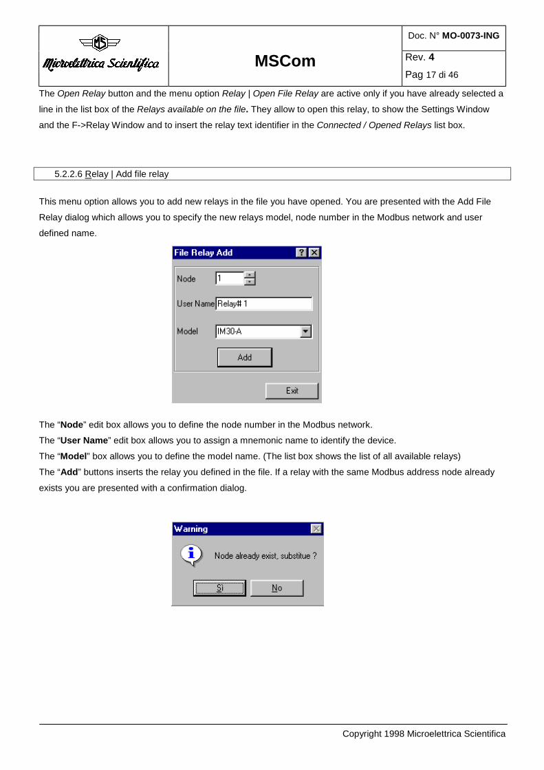
5.2.2.6 Relay | Add file relay
This menu option allows you to add new relays in the file you have opened. You are presented with the Add File
Relay dialog which allows you to specify the new relays model, node number in the Modbus network and user
defined name.
The “Node” edit box allows you to define the node number in the Modbus network.
The “User Name” edit box allows you to assign a mnemonic name to identify the device.
The “Model” box allows you to define the model name. (The list box shows the list of all available relays)
The “Add” buttons inserts the relay you defined in the file. If a relay with the same Modbus address node already
exists you are presented with a confirmation dialog.

Doc. N° MO-0073-ING
MSCom Rev. 4
Pag 18 di 46
Copyright 1998 Microelettrica Scientifica
5.2.2.7 Relay | Delete file relay This menu option allows you to delete a relay in the file you have opened. You are presented with the Delete File
Relay dialog which allows you to specify the node of the relay which you want to delete.
After you selected the “Delete” button you are presented with a confirmation dialog.
Answering “Yes” the relay at the specified node is deleted from the file and all relay data are lost.
NOTE: After you answered “Yes” the relay is deleted in a irreversible way.
5.2.2.8 Relay | Relay Manager
Please refer to §5.1
5.2.3 Measures menu
The Measurements Menu holds several options to display relay actual measurements, stored measurements,
counters and oscillographic data (when available).
5.2.3.1 Actual Measurements
The Measures | Actual Measurements menu option and the tool bar button show the Active Relay Actual
Measurements Window.
The Actual Measurements Window shows the actual values as measured during the relay normal operation . The
values displayed are continuously refreshed.
You can modify the refresh time modifying the Scan Time value in the Actual Measurements Window
Doc. N° MO-0073-ING
MSCom Rev. 4
Pag 19 di 46
Copyright 1998 Microelettrica Scientifica
Example: the UM30-A “Actual Measurements” Window
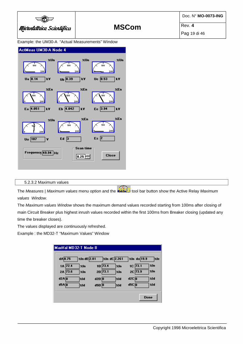
5.2.3.2 Maximum values
The Measures | Maximum values menu option and the tool bar button show the Active Relay Maximum
values Window.
The Maximum values Window shows the maximum demand values recorded starting from 100ms after closing of
main Circuit Breaker plus highest inrush values recorded within the first 100ms from Breaker closing (updated any
time the breaker closes).
The values displayed are continuously refreshed.
Example : the MD32-T “Maximum Values” Window
Doc. N° MO-0073-ING
MSCom Rev. 4
Pag 20 di 46
Copyright 1998 Microelettrica Scientifica
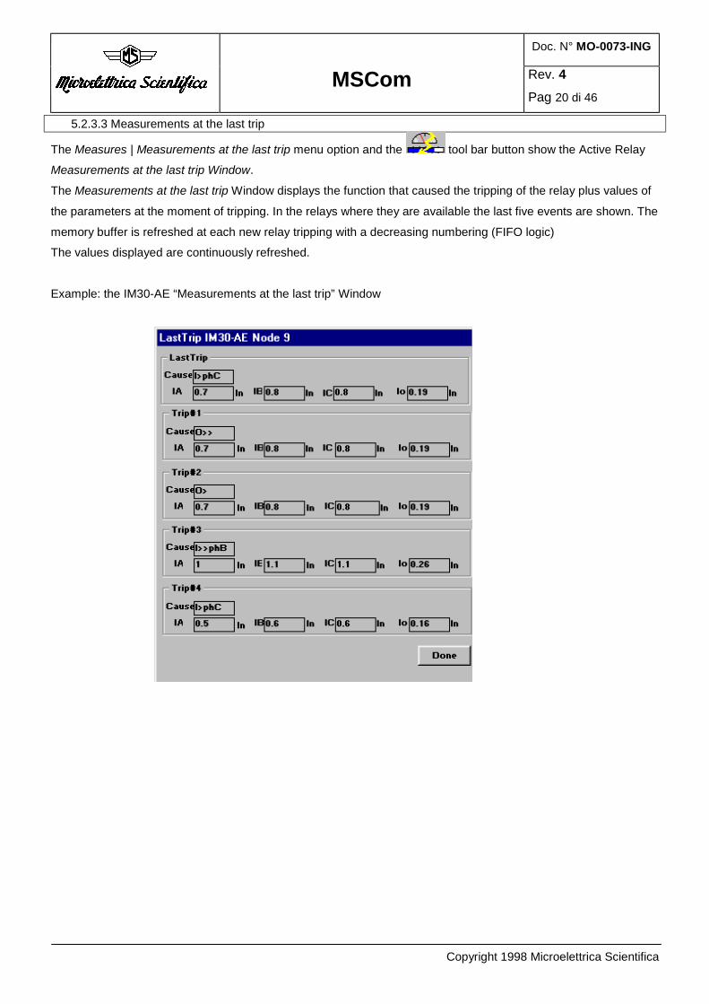
5.2.3.3 Measurements at the last trip
The Measures | Measurements at the last trip menu option and the tool bar button show the Active Relay
Measurements at the last trip Window.
The Measurements at the last trip Window displays the function that caused the tripping of the relay plus values of
the parameters at the moment of tripping. In the relays where they are available the last five events are shown. The
memory buffer is refreshed at each new relay tripping with a decreasing numbering (FIFO logic)
The values displayed are continuously refreshed.
Example: the IM30-AE “Measurements at the last trip” Window

Doc. N° MO-0073-ING
MSCom Rev. 4
Pag 21 di 46
Copyright 1998 Microelettrica Scientifica
5.2.3.4 Trip number
The Measures | Trips number menu option and the tool bar button show the Active Relay Trips number
Window.
TheTrips number Window shows the counters of the number of operations for each of the relay functions.
The values displayed are continuously refreshed.
Example: the MD32-T “Trips number” Window
5.2.3.5 Oscillographic data Recorder
The Measures | Event recorder menu option allows to send to the active relay the trigger command and to save the
oscillographic data.
The oscillograhic feature is available only in some relays (for example: MD32-T, MD32-G and MU30). If the Active
Relay hasn't this feature, the Measures | Event recorder menu option is disabled.
Clicking Measures | Event recorder, MsCom displays the Event recorder dialog
In the Events list box, some info about the last trigger events are showed.
If the relay hasn't an internal clock (i.e. the MD32-T and MD32 -G) no info about the trigger date/time is diplayed
and the Actual time text box is disabled. If the relay has been already triggered the Events list box displays
"Triggered".

Doc. N° MO-0073-ING
MSCom Rev. 4
Pag 22 di 46
Copyright 1998 Microelettrica Scientifica
The Trigger button sends to the relay a Trigger command: the relay stores in memory the oscillographic data.
Please refer to the on line documentation of the relay for more information.
The Update events button allows to update immediately the Events list box. Anyway the events list box is
refreshed automatically each 4 seconds.
The Save Data button allows to save the selected phase oscillographic data in a ASCII file on the hard-disk. This
file has the .xls extension and is compatible with Excel .The box at the right of the Events list box allows to select
one of the phase currents for the Save procedure.
The Save all data button allow to save all phase oscillographic data in different ASCII file. It’s necessary to give a
“common group name” to save files. These files have .xls extension and are compatible with Excel.
The Show data button send the oscillographic data to MSGraphic window.
5.2.3.5.1 MSGraphic
MSGraphic is a MSCom Pro additional tool displaying in graphical way the oscillographic data.
To see the graphic, select an event and the function (in the exemple “I1”) and push the button “Show Data”. Here below a “possible” result:
After some seconds the data will be loaded and you will be able to perform some operations using the
MSGraphic features:
You can resize the window, the graphics scale will be arranged automatically
Doc. N° MO-0073-ING
MSCom Rev. 4
Pag 23 di 46
Copyright 1998 Microelettrica Scientifica
To delete the displayed data push the “Clear” button.
To display the configuration window or to use the mathematical functions push the Options button.
The Print button prints the window graphic area . The standard print configuration features are available.
To load the file, in excel format, push the Load button.
To save the graphic in .bmp or .wmf format, push Save button.
The Close button hides MSGraphic without deleting the graphic data representation until the closure of
MSCom or the pressure of Clear button
A zoom feature is available: select the left up corner of the area you want to display and drag the mouse
cursor up to the right bottom corner. The displayed area will be the selected area as you release the mouse
button. To reset the zoom factor redo the same operation but from the right bottom corner to the left up
corner.
To display other data change the selection in the Oscillographic data recorder combo box and push the
Show data button. Another way to add new curves is to perform graphical operations on the already
displayed curves.
Warnings: the maximum number of curves displayed at the same time is 7.
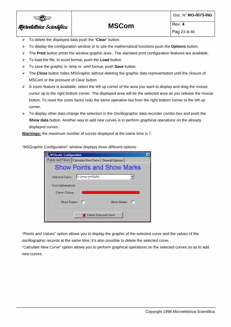
“MSGraphic Configuration” window displays three different options:
“Points and Values” option allows you to display the graphic of the selected curve and the values of the
oscillographic records at the same time; it’s also possible to delete the selected curve.
“Calculate New Curve” option allows you to perform graphical operations on the selected curves so as to add
new curves.

Doc. N° MO-0073-ING
MSCom Rev. 4
Pag 24 di 46
Copyright 1998 Microelettrica Scientifica
The available options are:
• Legend: you can assign to the calculated curve a new name; the default name is “Calculated”.
• Source1 and Source 2: these radio button group boxes allow to select the curves from which you calculate
the new curve.
• Operation: this combo box allows to select the mathematical operator.
• The Calculate button draws the new curve and closes the window.
Warning: the points of both curves involved in the mathematical transformation must have the same x
coordinates.
“General Options” window allows you to set the number of points for graphics and to display the curves in 3D
(this option is very useful when the curves are superimposed)

Doc. N° MO-0073-ING
MSCom Rev. 4
Pag 25 di 46
Copyright 1998 Microelettrica Scientifica
5.2.4 Settings menu
The Settings menu holds only two options, which allow to display the values of the relay’s operation parameters
(Settings) and the output relay associated to the different functions (F->Relay).
5.2.4.1 Settings
The Settings | Settings menu option and the tool bar button show the Active Relay Settings Window.
The Settings Window shows values of the relay's operation parameters as programmed.
The first time you open Settings Window, MSCom loads all the parameters from the relay. To reload the data after
any modification accomplished through the relay frontal keyboard, you must click on the Read button.
After any parameters modification in the Settings Window, you must click on the Send button to program the relay.
If the MSCom status is Read Only, the program will ask you to insert the password to enable the Read/Write
Status.
WARNING: When you close the Settings Window clicking on the Done button all the modified data are sent to the
relay.
Example The IM3G-V “Settings” Window:

Doc. N° MO-0073-ING
MSCom Rev. 4
Pag 26 di 46
Copyright 1998 Microelettrica Scientifica
5.2.4.2 F->Relay – Output Relays
The Settings | F->Relay menu option and the tool bar button show the Active Relay F->Relay Window.
The F->Relay Window shows the output relay associated to the different functions as programmed.
The first time when you open F->Relay Window, MSCom loads from the relay all the parameters. To reload the
data after any modification accomplished through the relay frontal keyboard you must click on the Read button.
After any parameters modification in the F->Relay Window, to program the relay you must click on the Send
button. If the MSCom status is Read Only the program will ask to insert the password to enable the Read/Write
Status.
WARNING: When you close the F->Relay Window clicking on the Done button all the modified data are sent to the
relay.
Example: the Im30-AE “Output relays” Window:

Doc. N° MO-0073-ING
MSCom Rev. 4
Pag 27 di 46
Copyright 1998 Microelettrica Scientifica
5.2.5 Status
The Status menu and the tool bar button show the Active Relay Status Window.
The Status Window shows the relay diagnostic and the protection function status for each of the relay functions.
The values displayed are continuously refreshed.
Example : The MD32-T “Status” Window:
5.2.6 Test Prg
The Test Prg menu and the tool bar button show the Active Relay Command Window.
The Command Window allows to send to the relay the commands to test the hardware and to accomplish special
operations.
The command buttons to test the hardware are :
Test only : to activate a complete test of the electronics and the process routines
Test + Trip : to activate a complete test which also includes the activation of all the output relays.
Example: The Um30-A “Test Prg” window:
Doc. N° MO-0073-ING
MSCom Rev. 4
Pag 28 di 46
Copyright 1998 Microelettrica Scientifica
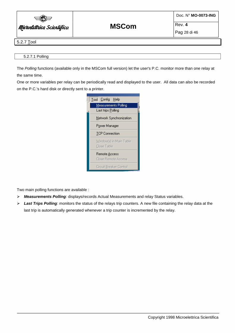
5.2.7 Tool
5.2.7.1 Polling
The Polling functions (available only in the MSCom full version) let the user's P.C. monitor more than one relay at
the same time.
One or more variables per relay can be periodically read and displayed to the user. All data can also be recorded
on the P.C.'s hard disk or directly sent to a printer.
Two main polling functions are available :
Measurements Polling: displays/records Actual Measurements and relay Status variables.
Last Trips Polling: monitors the status of the relays trip counters. A new file containing the relay data at the
last trip is automatically generated whenever a trip counter is incremented by the relay.

Doc. N° MO-0073-ING
MSCom Rev. 4
Pag 29 di 46
Copyright 1998 Microelettrica Scientifica
5.2.7.1.1 Measurements Polling
Selecting the Polling | Measurements Polling menu, MSCom displays the Measurements Polling Management
dialog .
The Data Output frame allows you to configure the required output device. Clicking the Printer radio button,
MSCom prints directly the data during the polling. Otherwise, clicking the Hard Disk radio button, MSCom
stores in an ASCII file the polling data. You must select Printer or Hard Disk before starting the polling.
The Start button starts the polling procedure and clears the list box showing the polling data.
The Stop button stops the polling procedure without terminating it. You can restart the polling clicking this
button again (which is changed in Continue button)
The End button terminates the polling procedure.
The Format File frame displays the file path used by the Polling procedure to find the Polling Data.
The Output File frame displays the file path used by the Polling procedure to create the output file if the Hard
Disk radio button in the Data Output frame is selected.
Checking the Data Auto Scroll box, the list box is continuously updated to show the last polling cycle data.
Disabling the Data Auto Scroll you are able to change the list box scroll bar position to examine the data
received in the past.
The Polling Real Time is the measured time between two Polling cycles. (i.e your required polling time is 0.4 s
but the achieved Polling Real Time is 0.75 s because you have specified in the polling format file a (too) long
data list to receive from the relays)

Doc. N° MO-0073-ING
MSCom Rev. 4
Pag 30 di 46
Copyright 1998 Microelettrica Scientifica
The Configuration button displays the Polling Data Config dialog which allows to modify the polling
configuration.
5.2.7.1.2 Measurements Polling Config
The Measurements Polling Config dialog is displayed by the Configuration button in the Measurements Polling
Management dialog.
This dialog allows to modify the Format Files. The Format file is an ASCII file that defines the polling data
output format.
The Header list box and the Data Lines list box show the 2 different parts of the format file contents. The first is
printed or saved on the disk only when you start the polling or restart after you have stopped it. The second
contains the definition of the data which are polled at each cycle. You can add in these parts whatever you want
to make the polling results clearer. The generic data format is:
[Node#-Variable name]
where # is the Relay Node number (in the Modbus network)
Variable name is one of the strings in Available variables list box
The separator between the Node definition and the variable name must be “-“. Here is an example:
[Node1-Ia] A [Node1-Ib] A

Doc. N° MO-0073-ING
MSCom Rev. 4
Pag 31 di 46
Copyright 1998 Microelettrica Scientifica
You can add the time stamping writing [TIMER ].
Example :
[TIMER ] [Node1-Ia] A [Node1-Ib] A
You can write the data definition manually or you can automatically insert the node and variable name selecting
the required variable in the Available variable list box, the node number in the Node selected frame and click the
Add button in the Available variable frame.
If you are working with the relays on line you can select a node with the Node Selected frame and click the
“Show var.” button: MSCom will show the Relay model and the available variables. Otherwise you can select
directly the Relay Model and MSCom will fill the Available Variables list box with the names of the variables
available in the Actual Measurements and in the Status Window.
The format file path is showed in the Format File frame.
The Open button allows you to load another format file. The Save button stores on the disk the format file which
is showed in the Header and in Data Lines list boxes.
Anyway, when you close the Polling Data Config Window clicking the OK button, MSCom will automatically
save the format file.
The Output File frame shows the file path for the polling data disk output .The Modify button allows you to
change this path. The output file is segmented in daily portions: data are never deleted, but added at the end of
each file.
5.2.7.1.3 Last Trips Polling
The Last Trips Polling option allows to control trip counter status.
Selecting the Polling | Last Trips Polling menu, MSCom displays the Last Trips Polling Management dialog.
This dialog is very similar to the Measurements Polling Management dialog of the Measurements Polling, the
only difference is the Configuration button that shows the Last Trips Polling Config Dialog.

Doc. N° MO-0073-ING
MSCom Rev. 4
Pag 32 di 46
Copyright 1998 Microelettrica Scientifica
Here below an example of the Last Trips Polling Management dialog.

Doc. N° MO-0073-ING
MSCom Rev. 4
Pag 33 di 46
Copyright 1998 Microelettrica Scientifica
5.2.7.1.4 Last Trips Polling Config
The Last Trips Polling Config dialog box is displayed by the Configuration button in the Last Trips Polling
Management dialog.
This dialog allows you to modify the Format Files of last trip (with extension .frp).
The format file is an ASCII file and contains general information, such as selected relays, scan time, compact
text status, etc.
The Header list box is a part of the format file and contains what is printed or saved on the disk only when you
start the last trip polling or restart after you have stopped it.
There are also 2 list boxes: Relay Available and Relay Selected.
The first one displays a list of relays available on the Network (if you haven't done scan network yet, no relay
will be displayed and a message will report it), while the second one displays a list of Relays that will be polled.
The Add button adds the selected relay to the Relay Selected List.
The Remove button removes the selected relay from the Relay Selected List.
The Add All button adds all the relays to the Relay Selected List.
The Remove All button removes all the relays from the Relay Selected List.
The 'Format File' group shows the format file name and allows to Open and Save a new format file.

Doc. N° MO-0073-ING
MSCom Rev. 4
Pag 34 di 46
Copyright 1998 Microelettrica Scientifica
The 'Output File' group does the same things with the output file name, but only the Save button is available in
this case.
The Check Node group allows the user to check whether or not a relay is present at a given node address. To
use this function, select the node number and click on the Check button. If a relay exists, it will be added to the
Relay Selected list.
The ScanTime group sets the Trip Counter polling time.
The Add Simulation Relays button adds all the available relays at node 0 to the 'Relay available' list; this
makes the function executable in simulation mode.
The Compact text button lets you compress the output text. There are three modes available:
• 'Compact text OFF': in this mode no output message is deleted.
• 'Compact text ON': in this mode all the groups of messages not containing a trip message are deleted.
• 'Compact MAX': in this mode only trip messages are displayed.
5.2.7.2 Network Synchronization
The protective relays clocks synchronization is performed by a broadcasting message (a message to node 0).
The Network Sync | Tool menu option displays the Network Synchronization Config dialog window.
Inside this dialog you can specify the synchronization messages frequency
To start the automatic synchronization select a synchronization time and push the “START Auto Synchronization”
button. A warning message will ask you to set correctly the TSync settings inside each protective relays connected
in the network.
Pushing the “Cancel” button inside the message box you can stop the procedure and set conveniently the TSync
values.

Doc. N° MO-0073-ING
MSCom Rev. 4
Pag 35 di 46
Copyright 1998 Microelettrica Scientifica
Pushing the “Ok” button inside the message box, if you inserted a correct value for the synchronization time, the
message box “Synchronization timer started.” appears and the Automatic Synchronization procedure starts.
On the top of the window a countdown counter starts: MSCom calculated the time before the next synchronization
time and used this value to set the initial point of the counter; now you can close the window. When the countdown
counter will be zero the broadcasting synchronization message will be sent out and a graphical confirmation
message (“Sending sync..”) will be showed on the screen for a couple of seconds. To stop the automatic
synchronization procedure, you have to push the “STOP Auto Synchronization” button.
When we talk about the Synchronization we mean that we set all the relays clocks at the same date and time.
Please refer to the Microelettrica Scientifica protective relays operation manual for more details about the TSyn
setting meaning and the Synchronization relays feature. Note: During the synchronization procedure we send:
- Date and time at the Modbus address 5120 (4 words)
- Latency Time at the Modbus address 5470.
- Synchronization command (we write the value 9 at the Modbus address 8000).
Latency time The synchronization message is a write Modbus message: it consists of 11 bytes. With a transmission baud rate of
9600 bit/s, the message is received by the relays after 11 milliseconds.
Since the required precision is 10 ms, we must take care of the transmission delay that we call “Latency time”
At the relays database we added a setting at the Modbus address 5470 to save the “Latency time” value.
When the relay receives the synchronization message it uses the value stored at the Modbus address 5470 to
recover the time lost during the transmission.
Latency time default = (1 / {Baud rate default }) * 10 * 11 * 1000
Obviously the Modbus master must update the Latency time in the Modbus slaves if the baud rate is changed.
This task is performed automatically by MSCom.
5.2.7.3 Remote Access
This menu option allows you to connect remote relays via 2 modems and a phone line.
After you selected the Tool / Remote Access menu, you are presented with a warning dialog:
This dialog allows you to change the active serial port: if you select “Yes” MSCom displays the
Communication Parameters Dialog (please refer to 5.2.8.4).

Doc. N° MO-0073-ING
MSCom Rev. 4
Pag 36 di 46
Copyright 1998 Microelettrica Scientifica
MSCom tries to initialize the modem reading the “Modem.ini” file and executing the AT commands listed (please
feel free to modify the modem.ini file saved in the MSCom directory to fulfill your special needs). If the initialization
procedure fails an error message will be displayed.
NOTE : to disable the menu option “Remote Access” and return to the normal functioning of serial communication,
select the option Tool / Close Remote Access .

Doc. N° MO-0073-ING
MSCom Rev. 4
Pag 37 di 46
Copyright 1998 Microelettrica Scientifica
In the table below you can find an example of the different functions in the different modem models.
Function Robotics
56k Fax
Modem
Generic
Modem with
Rockwell
chipset
Robotics
Flash x2
Trust
AE/AC
1414
BOCA
Modem
Strings for error codes DCE->DTE ( V0 =
Numbers, V1 = String)
V1 V1 V1 V1 V1
Only for modem connected to PC, no
AutoAnswer
s0=0 s0=0 s0=0 s0=0 s0=0
Only for modem connected to relays,
AutoAnswer
s0=2 s0=2 s0=2 s0=2 s0=2
Speaker disable M0 M0 M0 M0 M0
Dialing type
(T = Tone, P = Pulse )
T T T T T
DTE->DCE and
DCE->DCE fixed to 9600 baud with V32 or
V32bis modulation
&U6
&N6
&B1
&U6
&N6
&B1
&U6
&N6
&B1
N0
S37=9
N0
S37=9
Modulation Standard
( B0 = CCITT , B1 = BELL)
B0 B0 B0 B0
Data compression disabled &K0 &K0 &K0 %C0 %C0
Errors compression disabled &M0
S15=136
&M0
S15=136
&M0
S15=136
\N0 \N1
DCD data carrier status (enabled) &C1 &C1 &C1 &C1 &C1
Flow control RTS/CTS disabled &R1
&I0
&H0
&R1
&I0
&H0
&R1
&I0
&H0
&R1
&K0
&K0
DTR stop the communication &D2 &D2 &D2 &D2
&Q0
&D2
Disables monitoring of busy tones, enables
result codes
X0
Q0
X0
Q0
X0
Q0
X0
Q0
X0
Q0
Selection of starting configuration of the modem
(NVRAM profile 0)
&Y0
&Y0
&Y0
&Y0 &Y0
Save the current configuration as user profile 0 &W0
&W0
&W0
&W0 &W0
Function X2 disabled -
-
S32=32
S58=4
-

Doc. N° MO-0073-ING
MSCom Rev. 4
Pag 38 di 46
Copyright 1998 Microelettrica Scientifica
If the modem initialization procedure is completed successfully, you will be asked to insert the phone number to call
(an other modem with the auto-answer feature must be present at the phone number you specify)
If you insert a phone number and select “OK”, MSCom will try to create a phone connection with an other modem.
When the connection is created successfully an Info message is displayed, otherwise an error message provides
more info about the problem.
The connection modem-converter RS232/RS485 is never direct, but it always need a special cable, as displayed in
the following drawing:
In the table below you can find the correspondence between the input and output pin of the special cable
connecting modem and converter.
INPUT (from modem) OUTPUT (to converter)
1 – DCD 1 – DCD
2 – RD 3 – TX
3 – TD 2 – RX
4 – DTR 4 – DTR
5 – GND 5 – GND
6 – DSR 6 – DSR
7 – RTS 7 – RTS
8 – CTS 8 – CTS
9 – RI 9 - RI
Computer
Modem
retetelefonica
Modemrelè
RS232/485
cavo speciale

Doc. N° MO-0073-ING
MSCom Rev. 4
Pag 39 di 46
Copyright 1998 Microelettrica Scientifica
5.2.7.4 Circuit Breaker Control for MX....
The menu option Tool Circuit Breaker Control displays this window:
ON and OFF buttons allow to force outputs relay value (relay have to be set in “remote” mode): to update the
values of the outputs flags push these buttons. Inputs flags display the status of the inputs.
“Modify Inputs Labels” or “Modify Outputs Labels” buttons allow you to modify the labels of the flags both for the
inputs and for the outputs.

Doc. N° MO-0073-ING
MSCom Rev. 4
Pag 40 di 46
Copyright 1998 Microelettrica Scientifica
5.2.8 Config Menu
The Config Menu holds several options to modify MSCom password status and communication settings.
5.2.8.1 Enable Read / Write
The menu option Config | Enable Read/Write is active only if the program status is Read Only.
In the Read only program status button accomplishes the same function.
Selecting Config | Enable Read/Write or the tool bar button, MSCom will ask you to insert the password
throw the dialog
If you insert the right password, the program status will become Read/Write.
5.2.8.2 Disable Read/Write
The menu option Config | Disable Read/Write is active only if the program status is Read/Write.
Selecting Config | Disable Read/Write, MSCom returns in the Read Only status.
5.2.8.3 Change Password
The Config | Change Password menu option is active only if the MSCom status is Read/Write.
In the Read/Write program status tool bar button accomplishes the same function.
Selecting Config | Change Password or the button , MSCom will ask you to insert the password to enable
the Read/Write status and then, will ask you to insert the new password. Another request to insert the new
password checks if you didn't make any error typing the new password.

Doc. N° MO-0073-ING
MSCom Rev. 4
Pag 41 di 46
Copyright 1998 Microelettrica Scientifica
5.2.8.4 Communication parameters
The menu option Config | Communication parameters and the tool bar button allow to modify the active
serial port and baud rate.
Selecting this option, MSCom will display the Comunication parameters dialog:
Clicking on the OK button, MSCom checks if the selected Serial port is available. If the program detects an error, it
will avoid to close the dialog and will display an error message.
Time Out default value is “Short”: it’s better to change this value to “Long” when the connection is made trough
MCR relay or when the communication conditions are critical.
5.2.8.5 Retry Connection
The Config | Retry Connection menu option and the tool bar button are active only after a communication
error.
If the Active relay status is On line and MSCom can't communicate, the error message shown below is displayed
If you answer "NO", MSCom doesn't retry to communicate with the relay and makes active Config | Retry
Connection option and button.
The status frame displays "Communication Error".
Selecting Config | Retry Connection or , MSCom will retry to communicate with the relay.
Doc. N° MO-0073-ING
MSCom Rev. 4
Pag 42 di 46
Copyright 1998 Microelettrica Scientifica
5.2.9 Help This menu activates the “Help on Line”.
The option Help On Line Help displays the operation manual, in English or Italian, of the program MSComPro in
pdf version.
The option Help About shows the actual version of the program.
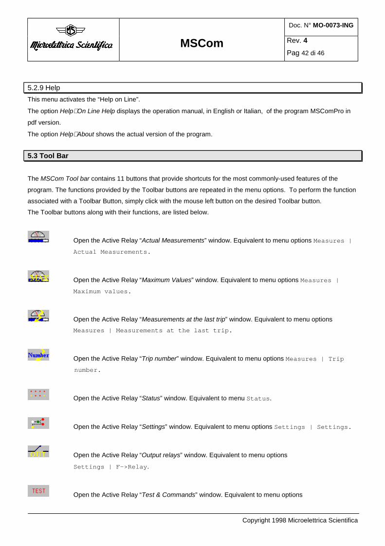
5.3 Tool Bar
The MSCom Tool bar contains 11 buttons that provide shortcuts for the most commonly-used features of the
program. The functions provided by the Toolbar buttons are repeated in the menu options. To perform the function
associated with a Toolbar Button, simply click with the mouse left button on the desired Toolbar button.
The Toolbar buttons along with their functions, are listed below.
Open the Active Relay “Actual Measurements” window. Equivalent to menu options Measures |
Actual Measurements.
Open the Active Relay “Maximum Values” window. Equivalent to menu options Measures |
Maximum values.
Open the Active Relay “Measurements at the last trip” window. Equivalent to menu options Measures | Measurements at the last trip.
Open the Active Relay “Trip number” window. Equivalent to menu options Measures | Trip
number.
Open the Active Relay “Status” window. Equivalent to menu Status.
Open the Active Relay “Settings” window. Equivalent to menu options Settings | Settings.
Open the Active Relay “Output relays” window. Equivalent to menu options
Settings | F->Relay.
Open the Active Relay “Test & Commands” window. Equivalent to menu options

Doc. N° MO-0073-ING
MSCom Rev. 4
Pag 43 di 46
Copyright 1998 Microelettrica Scientifica
Settings | TestPrg.
Open the “Communication Parameters” window. Equivalent to menu options Config |
Communication Parameters.
In case of communication error, retry to communicate. Equivalent to menu option Config |
Retry Connection.
If the program status is Read Only, it’s necessary to insert the Password to enable the Read/Write
Status. Equivalent to menu options Config | Enable Read/Write
If the program status is Read/Write, the button allows to change Password. Equivalent to menu
options Config | Change Password
atus bar
5.4 Status bar
The Status Bar located at the bottom of the MSCom main window displays various info about the Active Relay , the
program Status and the communication parameters.
5.5 Actual Measurements
5
Doc. N° MO-0073-ING
MSCom Rev. 4
Pag 44 di 46
Copyright 1998 Microelettrica Scientifica
5.5 New Tools
New functions, to improve network control, will be available in the next version of MSCom Professional.
These new functions will be:
TCP Connection
Windows in Main Table
Actually these tools are in pre-release: the functions are active (appear in the menu and are selectable), but only as
a demonstration.
Here below there is a short description of these tools operation.
5.5.1 TCP/IP connection
This feature allows to connect two PCs through the TCP/IP protocol and monitor the relays connected to the
remote PC serial port; the TCP/IP connection physical medium can be a LAN , a phone line to a modem on the
other PC or a phone line to an internet service provider.
The remote PC must run MSCom but the remote user can use his own copy of the program. Possible connection procedure and software requirements:
Through a LAN: Window95 or Windows 98.
Through remote access (i.e.: via modem): Windows 98 or Windows 95.
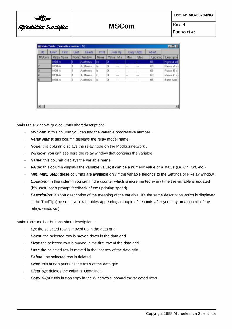
5.5.2 Windows in Main Table The “Windows in Main Table” menu option displays a window with an “old fashion” data browser: the data are
displayed in a grid. Data coming from more than one window and from different relays can be displayed in the
same data grid.
This menu is activated only when at least one relay is opened or connected and at least one window is on the
screen. Selecting “Windows in Main Table” the data available in the opened windows of the Active Relays will be
inserted in the “Main Table “ Window. The “Main Table “ Window doesn’t affect the performances of the serial communication. The data are required to
the opened relay windows without asking more data to the relay through the serial communication.
The variables showed in the “Main Table” window are updated only if the related relay windows are opened.
Doc. N° MO-0073-ING
MSCom Rev. 4
Pag 45 di 46
Copyright 1998 Microelettrica Scientifica
Main table window grid columns short description:
− MSCom: in this column you can find the variable progressive number.
− Relay Name: this column displays the relay model name.
− Node: this column displays the relay node on the Modbus network .
− Window: you can see here the relay window that contains the variable.
− Name: this column displays the variable name .
− Value: this column displays the variable value; it can be a numeric value or a status (i.e. On, Off, etc.).
− Min, Max, Step: these columns are available only if the variable belongs to the Settings or FRelay window.
− Updating: in this column you can find a counter which is incremented every time the variable is updated
(it’s useful for a prompt feedback of the updating speed)
− Description: a short description of the meaning of the variable. It’s the same description which is displayed
in the ToolTip (the small yellow bubbles appearing a couple of seconds after you stay on a control of the
relays windows )
Main Table toolbar buttons short description :
− Up: the selected row is moved up in the data grid.
− Down: the selected row is moved down in the data grid.
− First: the selected row is moved in the first row of the data grid.
− Last: the selected row is moved in the last row of the data grid.
− Delete: the selected row is deleted.
− Print: this button prints all the rows of the data grid.
− Clear Up: deletes the column “Updating”.
− Copy ClipB: this button copy in the Windows clipboard the selected rows.

Doc. N° MO-0073-ING
MSCom Rev. 4
Pag 46 di 46
Copyright 1998 Microelettrica Scientifica
Some useful advices to use the “Main table”:
To select a row, use the arrow keys on the keyboard to change the selected row or use the mouse and click on
the row you want to select.
To select more than one row, using the mouse, click and drag the mouse cursor, using the arrow keys on the keyboard, push the “SHIFT ” button.
To delete one or more rows, select the rows you want to delete and push the “Canc” button; a confirmation
message will appear.
The “Main Table” window is a stand alone program interfaced with MSCom. If The “Main Table” window is
overlapped by the MSCom standard windows, use the keyboard keys ALT and TAB to switch to the “Main
Table” application and to put it in foreground.
The “Main Table” window is useful if you want to monitor the behavior of some variables belonging to different
windows or to different relays. This feature is also nice if you want to print out only some variables in the order you
prefer.
5.5.3 Relay Demo
The menu option Relay | Open Demo Relay allows you to open a relay in demo mode (off line status)
Note: this option is active only if there is no Active Relay.
You are presented with the Demo Relay dialog which allows you to select the node number and the relay model.
The Ok button allows you to create the relay, after this all MSCom options, for Off Line status, will be available.
The Cancel button allows you to delate the operation.