MSC Software Composites Solution
50
MSC Software Composites Solution MSC Composites Technology Day
Transcript of MSC Software Composites Solution

MSC Software Composites Solution
MSC Composites Technology Day

Agenda for Today Time Agenda: Composites Technology Day with MSC Nastran
9:00-9:15 Welcome
9:15-9:45 Overview of MSC’s Composites Solution
9:45-10:30
Introduction to Analysis of Composites Structures
Hands-on Training
Workshop 1: Stress Analysis of a Composite Wing
10:30-10:45 Break
10:45-12:15
Solid Composite Elements
Hands-on Training
Workshop 2: Solid Shell Composites Modeling
12:15-12:45 Lunch
12:45-2:15
Progressive Ply Failure and Delamination Modeling
Hands-on Training
Workshop 3: Open-Hole-Tension Test Coupon
2:15-2:30 Break
2:30-4:00
Optimization of Composite Structures
Hands-on Training
Workshop 4: Minimizing the Weight of a Composite Wing
4:00-4:30 Curing, Draping, and Direct CAD Interface
4:30-4:45 Feedback/Wrap-up

Composites Technology Day, January 2012
Copyright 2012 MSC.Software Corporation 2
Global Composite Applications • What percentage of global composite fiber usage is
Carbon Fiber?

Composites Technology Day, January 2012
Copyright 2012 MSC.Software Corporation 3
Carbon Fiber Composite Applications

Composites Technology Day, January 2012
Copyright 2012 MSC.Software Corporation 4
2010 Distribution of Composite Applications

Composites Technology Day, January 2012
Copyright 2012 MSC.Software Corporation 5
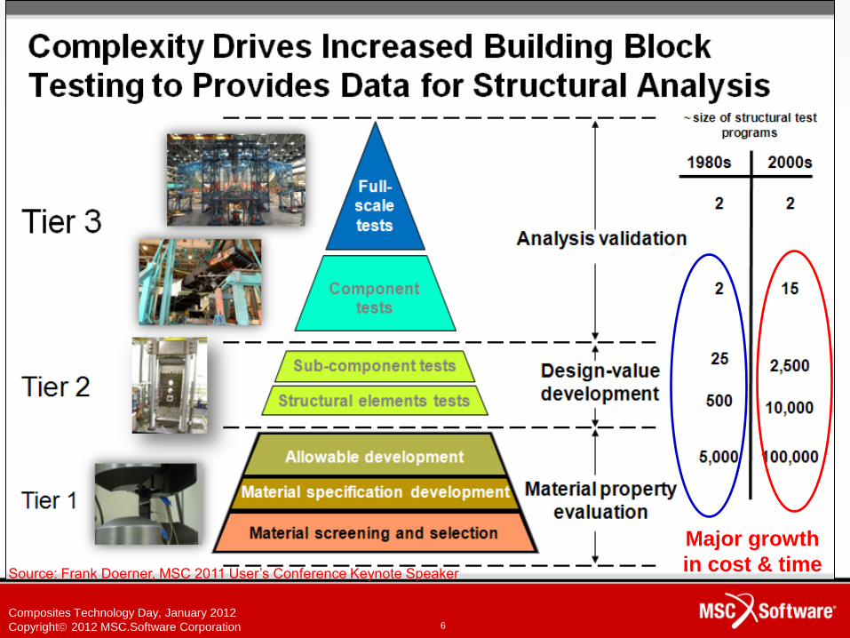
Aerospace Composites Usage • Boeing's 787 Dreamliner is
• 50% composite material by weight
• 80% composite materials by volume
• What were some of the challenges faced by this
composites program?
Composites Technology Day, January 2012
Copyright 2012 MSC.Software Corporation 6
Major growth
in cost & time Source: Frank Doerner, MSC 2011 User’s Conference Keynote Speaker

Composites Technology Day, January 2012
Copyright 2012 MSC.Software Corporation 7
Source: Frank Doerner, MSC 2011 User’s Conference Keynote Speaker

MSC Software
Composites
Solution
Extensive 1D, 2D, 3D composite
element library
Progressive Ply Failure
Analysis and Delamination
Optimization
Curing and Shrinkage
Draping and
CAD Interface
Static and Dynamics Analyses
Critical Margin
of Safety

Composites Technology Day, January 2012
Copyright 2012 MSC.Software Corporation 9
Extensive 1D, 2D, 3D Composite
Element Library

Composites Technology Day, January 2012
Copyright 2012 MSC.Software Corporation 10
MSC Software Composites Solution
• A comprehensive library of composite elements are supported in MSC’s pre/post processors and solvers
• FEA Solvers – MSC Nastran
– Marc
• Pre/Post Processors – Patran/Laminate Modeler
– SimXpert
– Mentat
• For today’s hands-on exercises we will use Patran and Nastran.

Composites Technology Day, January 2012
Copyright 2012 MSC.Software Corporation 11
Composite Elements Library
Shell Element
Solid Element
Beam Element

Composites Technology Day, January 2012
Copyright 2012 MSC.Software Corporation 12
Defining the Composite
• The general approach is to define a laminate
material representation of the layup
1. Define the ply material properties first
2. Then define the laminate – ply
thickness, orientation, and layup
sequence
3. Assign the laminate to elements
Composites Technology Day, January 2012
Copyright 2012 MSC.Software Corporation 13
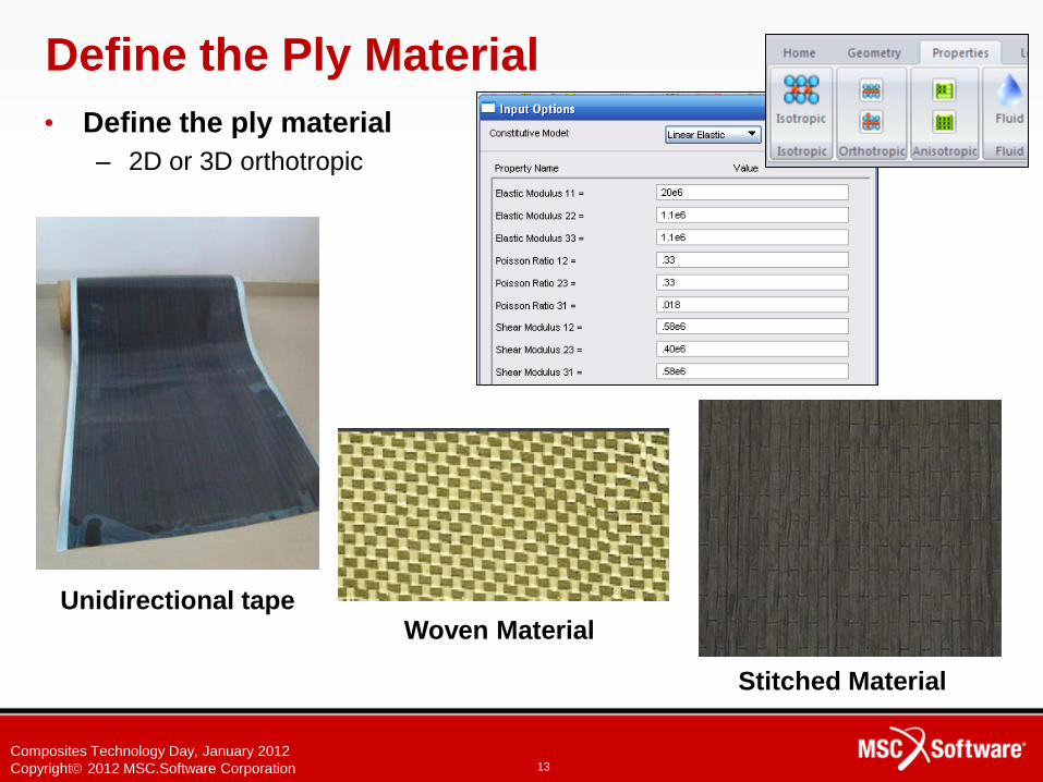
Define the Ply Material
• Define the ply material
– 2D or 3D orthotropic
Unidirectional tape Woven Material
Stitched Material

Composites Technology Day, January 2012
Copyright 2012 MSC.Software Corporation 14
User-friendly interface to define the laminate
• Define the layup
– Material
– Thickness
– Orientation angle

Composites Technology Day, January 2012
Copyright 2012 MSC.Software Corporation 15
2D and 3D Composite Elements
• Shell and solid composite elements
– Both support progressive ply failure analysis
– Two types of solid composite elements
2
1
3
2
Solid Layered Composites
1
3
2
One integration point per layer
Solid Shell Composites

MSC Software
Composites
Solution
Extensive 1D, 2D, 3D composite
element library
Progressive Ply Failure
Analysis and Delamination
Optimization
Curing and Shrinkage
Draping and
FiberSIM Interface
Static and Dynamics Analyses
Critical Margin
of Safety

Composites Technology Day, January 2012
Copyright 2012 MSC.Software Corporation 17
Static and Dynamics
Analyses

Composites Technology Day, January 2012
Copyright 2012 MSC.Software Corporation 18
Static and Dynamics Strength Evaluation
• Static Analysis and Dynamics Analysis
– Stress and Strain computation
– Failure Theories
– Failure indices
– Strength ratios

Composites Technology Day, January 2012
Copyright 2012 MSC.Software Corporation 19
Geometry Zone Layup Ply Layup Ply Details Verification
Simulate Simulate Simulate Simulate
Manufacture
OK!
feedback loop ...
Zone vs. Ply Layup
Detailed
design Preliminary
design

Composites Technology Day, January 2012
Copyright 2012 MSC.Software Corporation 20
Results Viewable by Layer Number or Global Ply ID
View by Layer Number
Layer 1
Layer 2
Laye
r 3
View by Global Ply ID
Glo
bal P
ly 1
G
lobal P
ly 2
G
loba
l P
ly 3

Composites Technology Day, January 2012
Copyright 2012 MSC.Software Corporation 21
Define plies Define Layup
Ply Based Modeling in Laminate Modeler
Show/Verify Layup
• Ply based approach

MSC Software
Composites
Solution
Extensive 1D, 2D, 3D composite
element library
Progressive Ply Failure
Analysis and Delamination
Optimization
Curing and Shrinkage
Draping and
FiberSIM Interface
Static and Dynamics Analyses
Critical Margin
of Safety

Composites Technology Day, January 2012
Copyright 2012 MSC.Software Corporation 23
Optimization
of
Composites
Composites Technology Day, January 2012
Copyright 2012 MSC.Software Corporation 24
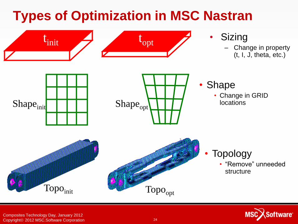
Types of Optimization in MSC Nastran
• Sizing – Change in property
(t, I, J, theta, etc.)
tinit topt
Shapeinit Shapeopt
Topoinit Topoopt
• Topology • “Remove” unneeded
structure
• Shape • Change in GRID
locations

Composites Technology Day, January 2012
Copyright 2012 MSC.Software Corporation 25
Types of Optimization in MSC Nastran
• Topography
– Special form of shape
optimization
• Topometry
– Special form of sizing
optimization
– Each element is
separately designed
All elements with same
initial thickness
Varied thickness after
optimization
Initially “flat” sheet Optimized with “bead”

Composites Technology Day, January 2012
Copyright 2012 MSC.Software Corporation 26
Composites in Optimization
• Composites optimization is
specifically supported in
– Sizing optimization
– Topometry optimization

Composites Technology Day, January 2012
Copyright 2012 MSC.Software Corporation 27
Sizing Optimization
• Objective
– Minimize weight
– Minimize compliance
– Etc.
• Design Variables
– Ply orientation
– Thickness
– Material properties
• Constraints
– Failure indices
– Strength ratios
– Weight
– Stress
– Strain
– Etc.

Composites Technology Day, January 2012
Copyright 2012 MSC.Software Corporation 28
Sizing Optimization Sizing Optimization
• Composite sizing optimization example
– Optimize ply angles
– Optimize ply thicknesses
– Minimize weight 45
o
5o
Ply Angles
0.06
Ply Thickness
Initial weight = 1.598
Final weight = 9.589E-2
Total Weight

Composites Technology Day, January 2012
Copyright 2012 MSC.Software Corporation 29
Topometry Optimization
• Topometry optimization for
composites
– Material distribution is optimized
across all elements
– Ply-by-ply element thickness
optimization
0 degree Ply 90 degree Ply +45 degree Ply -45 degree Ply
Composite element
combined thickness distribution

MSC Software
Composites
Solution
Extensive 1D, 2D, 3D composite
element library
Progressive Ply Failure
Analysis and Delamination
Optimization
Curing and Shrinkage
Draping and
FiberSIM Interface
Static and Dynamics Analyses
Critical Margin
of Safety

Composites Technology Day, January 2012
Copyright 2012 MSC.Software Corporation 31
Progressive Failure Analysis (PFA) and
Delamination

Composites Technology Day, January 2012
Copyright 2012 MSC.Software Corporation 32
Going Beyond First-Ply-Failure (FPF)
• Evaluate the load redistribution in a composite
structure as the plies fail progressively
32
• Simulate delamination growth from initial flaw
• Study crack propagation to design for fail-safe
structures

Composites Technology Day, January 2012
Copyright 2012 MSC.Software Corporation 33
33
VCCT CZM
Delamination Breaking Glue PFA
Failure and Delamination Methods
Ply Material
Failure Delamination

Composites Technology Day, January 2012
Copyright 2012 MSC.Software Corporation 34
Progressive Failure Analysis (PFA) • The user selects the failure criteria
– Puck, Hashin, Tsai-Wu, etc.
• Composite failure on a layer by layer basis
• Upon failure, scale down E and G
Pin bearing on hole

Composites Technology Day, January 2012
Copyright 2012 MSC.Software Corporation 35
Animation shows region
released from glued
Animation shows glued
region
VCCT Example – delamination growing along
glued interface
Composites Technology Day, January 2012
Copyright 2012 MSC.Software Corporation 36
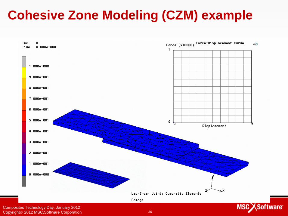
Cohesive Zone Modeling (CZM) example

Composites Technology Day, January 2012
Copyright 2012 MSC.Software Corporation 37
Breaking Glued Contact example
• Release glued contact
when the following stress
criterion is met
• Use contact normal and
tangential stresses
• After break, do regular
contact with friction and
separation

Composites Technology Day, January 2012
Copyright 2012 MSC.Software Corporation 38
• Split up mesh between materials or within a material when the following stress criterion is met
• Use stresses normal and tangential to interface
Delamination example

MSC Software
Composites
Solution
Extensive 1D, 2D, 3D composite
element library
Progressive Ply Failure
Analysis and Delamination
Optimization
Curing and Shrinkage
Draping and
FiberSIM Interface
Static and Dynamics Analyses
Critical Margin
of Safety

Composites Technology Day, January 2012
Copyright 2012 MSC.Software Corporation 40
Curing and Shrinkage
during
Manufacturing

Composites Technology Day, January 2012
Copyright 2012 MSC.Software Corporation 41
MSC Composite Curing Capability
• Cure-induced heating and curing shrinkage
– Thermal heat generation due to curing
– Shrinkage strains associated with curing
– Causes distortion and residual stress in parts
– Prediction is critical for predicting final shape
• Coupled thermo-mechanical analysis
– Critical capability for process development
– Available for solid and shell elements
– Marc has this unique capability in the industry

Composites Technology Day, January 2012
Copyright 2012 MSC.Software Corporation 42
0°/90°, +/- 45°
Case Study : Sikorsky S-92 Helicopter
Orthotropic Layup

Composites Technology Day, January 2012
Copyright 2012 MSC.Software Corporation 43
Case Study
.345” predicted
Springback
.35” actual

MSC Software
Composites
Solution
Extensive 1D, 2D, 3D composite
element library
Progressive Ply Failure
Analysis and Delamination
Optimization
Curing and Shrinkage
Draping and
FiberSIM Interface
Static and Dynamics Analyses
Critical Margin
of Safety

Composites Technology Day, January 2012
Copyright 2012 MSC.Software Corporation 45
Draping and FiberSIM Interface

Composites Technology Day, January 2012
Copyright 2012 MSC.Software Corporation 46
Laminate Modeler
• Process simulation
– Ply draping
– Scissor - draping
behavior exhibited by
fabrics
– Slide - draping behavior
exhibited by tapes
– Splits and darts
• Direct interface to CAD
– FiberSIM

Composites Technology Day, January 2012
Copyright 2012 MSC.Software Corporation 47
Define plies Define Layup
Ply Draping Simulation in Laminate Modelr
Show/Verify Layup
• Define ply material and layup on doubly curved surfaces

Composites Technology Day, January 2012
Copyright 2012 MSC.Software Corporation 48
Interface to FiberSIM
• Directly access layup data from
FiberSIM
– FiberSIM plies and layup files are
imported and mapped onto analysis
mesh

Composites Technology Day, January 2012
Copyright 2012 MSC.Software Corporation
End of Composites Solution
Overview
49