MSC-05805 - NASA · APOLLO 15 MISSION MAIN PARACHUTE FAILURE Anomaly Report No. 1 PREPARED BY...
33
MSC-05805 NATIONAL AERONAUTICS AND SPACE ADMINISTRATION (NASA-TM-X-6835() PARACHUTE FAILURE (NASA) Dec. 1971 ::::::::::::::::::::::: -:-:-:·:· :-: -:·:.:. :·:· ·.·.·.·.·.·.·.·.·.·.·.· ::::::::::::::::::::::: :-:·: -: ·=·:.: ·:·: -: -:·: .·.·.·.·.·.·.·.·.·.·.·. ::::::::::::::::::::::: .·.·.·.·.·.·.·.·.·.·.· . . ·.·.·.·.·.·.·.·.·.·.·. ·= .. : .. :· :-:.:. :·:.:. :· :· ::::::::::::::::::::::: .·.·.·.·.·.·.·.·.·.·.·. ::::::::::::::::::::::: ::::::::::::::::::::::: ·.·.·.·.·.·.· .. ·.·.·.·.· ::::::::::::::::::::::: ::::::::::::::::::::::: :::·:·:·········;·;·£= APOLLO 15 MISSION ANOMALY REPORT NO. 1 MAIN PARACHUTE FAILURE APOLLO 15 MISSION Anomaly Report no. MAIN 1 N72-25848 32 p CSCL 22C G3/31 Unclas 27572 DISTRIBUTION AND REFERENCING This _paper is not far general distribution or referenctng. It may be referenced only 1n other work•ng correspondence and documents !ly participating organizations. MANNED SPACECRAFT CENTER HOUSTON.TEXAS DECEMBER 1971
Transcript of MSC-05805 - NASA · APOLLO 15 MISSION MAIN PARACHUTE FAILURE Anomaly Report No. 1 PREPARED BY...

MSC-05805
NATIONAL AERONAUTICS AND SPACE ADMINISTRATION
(NASA-TM-X-6835() PARACHUTE FAILURE (NASA) Dec. 1971
::::::::::::::::::::::: -:-:-:·:· :-: -:·:.:. :·:· ·.·.·.·.·.·.·.·.·.·.·.· ::::::::::::::::::::::: :-:·: -: ·=·:.: ·:·: -: -:·: .·.·.·.·.·.·.·.·.·.·.·. ::::::::::::::::::::::: .·.·.·.·.·.·.·.·.·.·.· . . ·.·.·.·.·.·.·.·.·.·.·. ·= .. : .. :· :-:.:. :·:.:. :· :· ::::::::::::::::::::::: .·.·.·.·.·.·.·.·.·.·.·. ::::::::::::::::::::::: ::::::::::::::::::::::: ·.·.·.·.·.·.· .. ·.·.·.·.· ::::::::::::::::::::::: ::::::::::::::::::::::: :::·:·:·········;·;·£=
APOLLO 15 MISSION
ANOMALY REPORT NO. 1
MAIN PARACHUTE FAILURE
APOLLO 15 MISSION Anomaly Report no.
MAIN 1
N72-25848
32 p CSCL 22C
G3/31 Unclas 27572
DISTRIBUTION AND REFERENCING
This _paper is not ~uitoble far general distribution or referenctng. It may be referenced only 1n other work•ng correspondence and documents !ly participating organizations.
MANNED SPACECRAFT CENTER HOUSTON.TEXAS
DECEMBER 1971

APOLLO 15 MISSION
MAIN PARACHUTE FAILURE
Anomaly Report No. 1
PREPARED BY
Mission Evaluation Team
APFROVED BY
_L,o_~g~ James A. McDivitt
· Colonel~ USAF Marl er ~ Apollo Spacecraft. Program
NATIONAL AERONAUTICS AND SPACE ADMINISTRATION
MANNED SPACECRAF'r CENTER
HOUSTON, TEXAS
December 1971
MSC-05805

1
MAIN PARACHUTE FAILURE
The three main parachutes of the Apollo 15 spacecraft deployed and inflated properly at approximately 10 000 feet altitude. Films show that all three p~achutes disreefed and opened fully in the proper sequence. The spacecraft and its parachutes were obscured by clouds at about 7000 feet altitude. Upon emerging from the clouds at about 6000 feet altitude 9
one of the three main parachutes was deflated as shown in figure 1. The spacecraft and parachute system descended in this configuration to water landing. The three parachutes were disconnected and one of the good main parachutes was recovered. The failure occurred abruptly. At about the altitude and time of the failure 9 the forward heat shield was in close proximity to the spacecraft and the reaction control system propellant depletion firing was about completed. An inspectior1 of the recovered parachute showed one of the six riser links had a broken stud and three others had cracks. The inve~tigation of the failure was 9 therefore, focused on the reaction control system propellant depletivn firing. the forward heat shield, and the failed links.
DESCRIPTION AND SYSTEM OPERATION
The earth landing system decelerates and stabilizes the command module to safe conditions for landing. The landing sequence is initiated at a nominal altitude of 24 000 feet with jettisoning ~f the forward heat shield. In:anediately after separation of the he~:.t u~:ield from the command module, a 7 .2-foot-diameter parachute is mortar ... dE:T•loyed from the forward heat shield. This parachute prevents initial reco{.tact between the heat shield and the command module.
Two 16.5-foot diameter conical ribbon~type drogue parachutes are mortar-deployed 1.6 seconds after forward heat sl:ield .1ettison. The drogue parachutes are deployed in a reefed condition and, LO seconds later, in ... fla.te to the fully open configuration. The drogue ;>arachutes are released from the command module at an altitude of abcut 11 JOO feet. At drogue parachute disconnect! three 7 .2-foot diameter l''ing.-slot pilot parachutes are mortar-deployed. The pilot parachutes provide the force necessary to release the m&in parachute retention system and pul~ the main parachute pack assemblies from the upper deck. As the main parachute packs are pulled away from the command module, the parachute::; are extracted from their deployment bags. Each main parachute infl-~es through two reefing stages to the fully open configuration. The thre·e main parachute assemblies (fig. 2) decelerate the command module to the final descent velocity.
Et..~h main parachute canopy consists of twelv.~ rings of sails with each ri · divided into 68 gores. The canopy terminates in 6A suspension


4
lines which are attached by six steel connector links tu ~ix individual legs of a fabric riser. The six legs of the fabric ris~r coverge into a single leg which connects tc the end of a steel cable riser. The three steel cable risers of th~ parachute system coverge and attach to the command module through the parachute attachment and disconnect assembly.
DISCUSSION
A discussion of the analysis, tests, conclusions, anL ~orrective actions are contained in this report. All times sho~~ in t~is report are elapsed time from range zero. Range zero is the nearest integral second prior to lift-off.
FLIGHT DATA
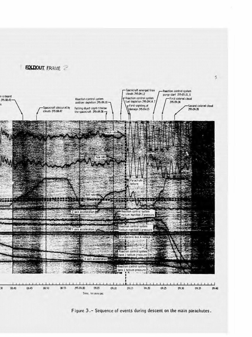
Pertinent data and the sequence of events are shown in figure 3. The data showed no abnormal conditions or events prior to the fai~~e. About 3.5 seconds before the failure, the reaction control system manifold pressure abruptly increased to a new level, indicating the regulator had closed because all the oxidizer was expelled from the tanks. The fuel, however, was still being expelled and was calculated to have been depleted about 4. 7 seconds after the oxidizer depletion. This was based on a determination of about 7 pounds of fuel remaining at oxidizer deple~ tion. About 8 seconds after the failure, the reaction control system purge was ini tia.ted by the crew. (The crew was unaware of the failure until some time after the purge.) The time of the purge is indicated in figure 3 by the abrupt decrease in system pressure.
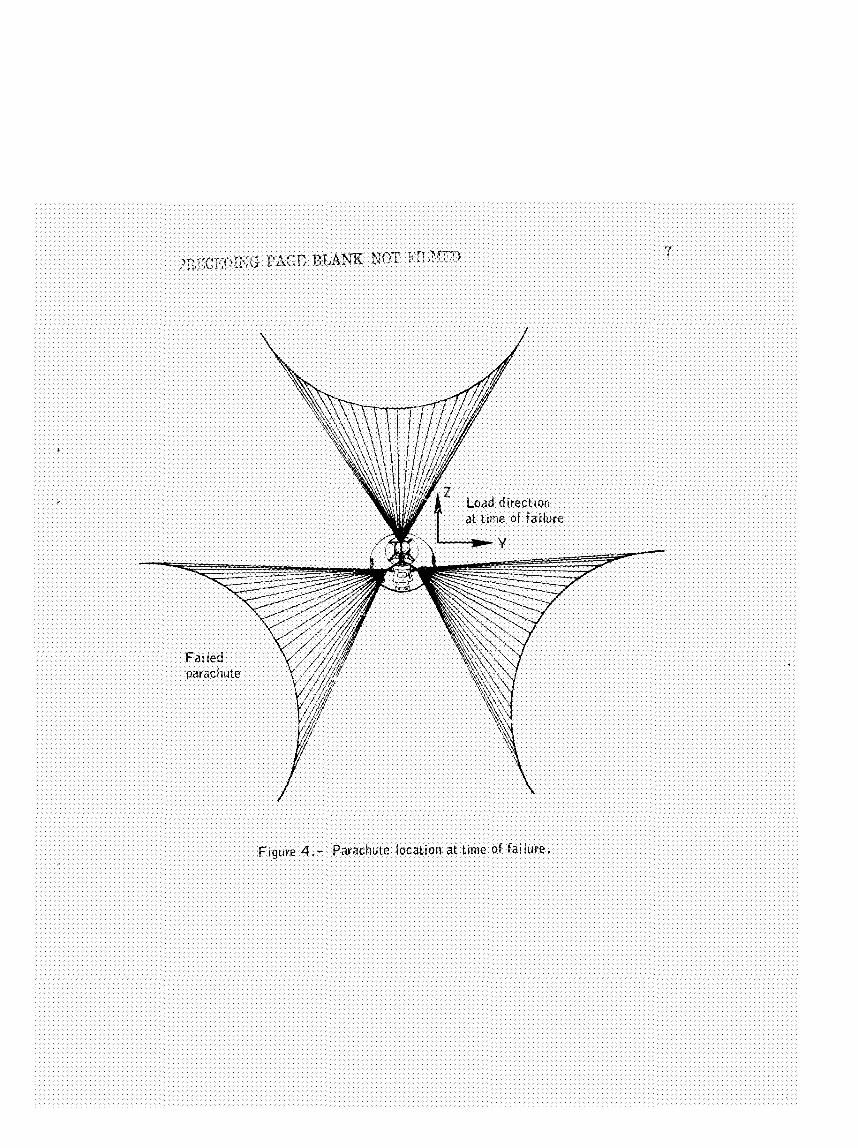
The forces acting upon the spacecraft at ihe time the parachute failed were determined from body-mounted accelerometer data. The force vector change at the parachute attach point was:
F = -1379 X + 356 Y + 886 Z pounds - - - -This resultant vector locates the failed parachute as shmm in fig
ure 4. The computed force vector was substantiated by body~mounted rate gyro data.
PHOTOGRAPHIC DATA
Figure 5 shows the spacecraft and lower parachute system when the spacecraft was relatively close to landing. The following observations resulted from study of this figure and other photographic data.


Failed parachute
BLANK NOT
Figure 4.- Parachute location at time of failure.
7

9
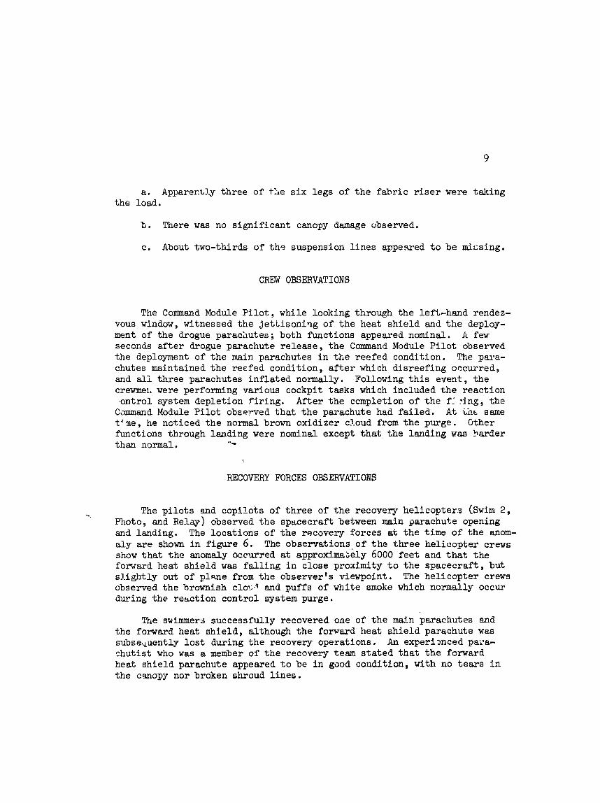
a. Apparer.tJ.y three of t::-!e six legs of the fabric riser were taking the load.
b. There was no significant canopy damage 0bserved.
c. About two-thirds of th~ suspension lines appe~.red to be mi:.:sing.
CREW OBSERVATIONS
The Command Module Pilot, while looking through the left ... hand rendezvous window, witnessed the jetlisoni~g of the heat shield and the deployment of the drogue paracautes; both functions appeared nominal. A few seconds after drogue parachute release, the Command Module Pilot observed the deployment of the main parachutes in the reefed condition. The parachutes maintained the reefed condition, after which disreefing o~curred, and all three parachutes inflated normally. Following this event, the crewme1~ were performing various e:ockpi t tasks which included the reaction ·antral system depletion firing. After the completion of the r: ~ing, the
c,·llnmand Module Pilot obsP.rved thut the parachute had failed. At ·i.il.t same t~ :ne, he noticed the normal brown oxidizer cJ.oud from the purge. Other functions through landing were nominal except that. the landing was ~arder than normal. ~-
RECOVERY FORCES OBSERVATIONS
The pilots and copilots of three of the recovery helicopter.:; (Swim 2, Photo, and Relay) observed the sp~cecraft between main parachute opening and landing. The locations of the recovery forces at the time of the anomaly are shown in figure 6. The observations.of the tl~ee helicopter crews show that the anomaly oc~urred at approxima~ely 6000 feet and that the forward heat shield was falling in close proximity to the spacecraft, but sJ.ightly out of pll=l.tle from the observer 1 s viewpoint. The helicopter crews observed the brownish clo•.;--'~ and puffs of white smoke which normally occur during the re~ction control system purge.
The swimmer3 successfully recovered one of the main parachutes and the forward heat shield, although the forward heat shield parachute was subse'-!uently lost during the recovery operations. An experi :meed pa:..·a~hutist who was a member of the recovery team stated that the forward heat shield parachute appeared to be in good condition, with no tears in the c~opy nor broken shroud lines.

Swim 1 4000 ft.
~
0
North
t
5
Nautical miles
Russian ship~
Okinawa\
10
Photo 2400 ft.
Recove>ry ® 1500 ft.
~Relay 8000ft.
Swim 2 5200ft.
Spacecraft 6200ft.
• ~
Figure 6.- Approximate location of recovery forces at 295 hours 9 min"f"":,.
b

ll
RECOVERED PARACHUTE INSPECTION
The recovered main parachute which had not failed was inspected and the results of the insrection were:
a. Nine consecutive suspension lines were cut approximately 19 feet above the riser/suspension-line connector link. Additionally, s~e 25 feet of line was missing from each of the eut suspension lines. (Lines were cut by Navy swimmers to free the parachute from the command module.)
b. Gore ll of panel 9 had a tear approximately 12 inches by 12 inches which did not appear to have been caused by stress or friction burning, but probably occurred during retrieval.
c. Gore 55 of panel 5 had an 8-inch horizontal tear which also appeared to be the result of retrieval or postflight handling operations rather than that of flight damage.
d. There were numerous small (l/l6~inch to l/4~inch) holes in the canopy. (These were probably caused by postflight handling.)
e. The pilot parachute and riser were in excellent condition, and the main parachute deployment bag had only minimal (normal) damage.
f. The canopy was stained with oil and grease.
g. A broken riser/suspension-line connector link was found after the prote~tive Dacron boot1e had been removed (fig. 7).
h. Evidence of high temperature was noted on the Dacron riser pro~ tective cover (fig. 8} and the Dacron connector link bootie.
FORWARD HEAT S~IELD INSPECTION
The overall appearance of the forward heat shield was consistent with that of the fo1~ard heat shields previously recovered. The heat shield was examined for evidence of foreign material and none was found. The following specific points were noted:
a. The leading edge seal was not damaged.
b. Parachute cable riser marks were present on the outside of the fo~iard heat shield. These marks occurred as a result of the normal forward heat shield parachute deployment.


14
c. The forward heat shield mortar had fired and the ramp had its normal scratches. One pyrotechnic connector was bent, probably as aresult of ground handling.
d. The handrail had been severely heated and approximately ·7 inches of rail was missing. This condition was caused by reentry heating.
e. The minus Z ~ide was slightly flattened from impact with the water.
f. The l&...y....rus and pins from the forward heat shield switch appeared to be normal.
g. The umbilicals appeared to be normal.
h. A slice from the base of the ablator (7 inches by 1.5 inches by 0.75 inch) on the plus Z side was missing, but the room-temperature vulcanizing seal was undamaged. The damage to the ablator was probably caused by the recovery operation.
i. All forward heat shield thrusters appeared to have functioned normally from. the appearance of the area surrounding the piston rods.
j. Approximately 50 inches of the fabric parachute riser were still attached to the steel riser. The fabric portion of the forward heat shield riser was cut by the swimmers.
FAILURE ASSESSMENT
The investigation was essentially divided into three areas which were likely suspects as to the cause of the parachute failure.
l. The forward heat shield was suspect because of the close proximity of the heat shield to the spacecraft flight path during the period when the failure occurred.
2. A broken riser/suspension-li~e connector link was found on the recovered parachute indicating the possibility of broken links in the failed parachute.
3. The command module reaction control system propellant depletion firing had just been completed and fuel expulsion was in progress at the time of the failure, indicating the possibility of damage from the propellants.
The analyses and tests performed to investigate each possibility are presented in the following paragraphs.

15
Forward Heat Shield
Trajectory analysis.- A trajectory analysis was performed using simulations to determine if the forward heat shield could have contacted the main parachu+es. The simulations were based on the point-mass equations of motion, which used the known mass and aerodynamic characteristics of the forward heat shield and spacecraft parachute systems and the measured downrange and crossrange winds.
The simulations and analysis showed that, at approximately 150 seconds after the 24 000-foot altitude had been reached, the spacecraft and fo~vard heat shield were at the same altitude of about 5700 feet with a miss dastance of approximately 150 feet. This correlates with observations of the recovery personnel. Further, the analysis indicates that, at landing, the spacecraft and the forward heat shield were about 850 feet apart. This agrees with the estimated separation distance of 900 feet on the water.
Since the wind data were measured several minutes before landing, some deviations were expected. A wind profile within the expec·'- :d deviation of ±2 knots was constructed to determine if contact between the forward heat .shield and command module parachute system was possible.
Based on the wind profile trajectory simultdions, the forward heat shield could have contacted the spacecraft parac1~ute system at an altitude near 6000 feet. The inaccuracies in the measured data and the simulations are such that it cannot be conclusively stated that the contact did or did not occur. It can only be stated that, in all probability, the miss distance was small.
Photographic analysis.- A close examination of the television record of spacecraft descent on the main parach~tes establishes that the forward heat shield was below the spacecraft at tre time of the failure. Specifically, the forward heat shield is seen below the spacecraft in frame 588 (fig. 9) at 295:09:11:3, approximately 2 seconds before the anomaly occur~ red. By correlation with frame 775, which shows the parachute and forward heat shield in the same frame at 295:09:17.5, and by direct measurement of the separation distance between the two objects and measurement of the known parachute dimensions, the vertical separat~.on distances between the forward heat shield and the spacecraft were 58o feet for frame 588 and 1020 feet for frame 775.
The position of the forward heat shield relative to the guidanceand-navigation-estimated trajectory is shown in figure 10. By extrapolating the forward heat shield trajectory, the forward heat shield would have intercepted the spacecraft at 295:09:03. This is 10.5 seconds before the spacecraft data indicate the anomaly occurred.

Television frame 588
295:09:11.3 elapsed time
~H = j·.~i <1020 ft.)= 580ft
~H =580ft
Television frame 775
295:09:17.5 elapsed time
t.H = 574 <60/33) ft = 1042 ft
or 574 (140/80)ft = 1004 ft
~H = 1020 ft
't 1
Direct measurement 4.04 inches
"_j_ 633units~
,til I 1
~~~~;1'\~I@;);J~ " 80 units~ 140 ft
't [;;;' -- ----+--
574 units
<Direct measurement- 7.11 in.)
9----......... -
-------- ------- - -------~V = 1020- 580 ft/sec
17.5-11.3
~V =71ft/sec
Figure 9.- Television frame and trajectory analysis.

6400 r-.. --6000
........ r--r-...
Apollo 15 command mod•Jie
5600 t-- best estimate trajectory
~ 5200 Q; Tl
-~ ~
~ 4800
4400
4000
3600 295:08:42 295:08:50
"\I, :
,, tr ~----"
~ ~ t- Command :..._
i module Probable-~ ."' ........... 1-Q. intercept ""'-1-.
L\Hc5so ft ! --.c ~ :
"" L\H 2=1020 ft
~.l . :
1\.. :
~' ~ J '
V object - V eM= 71 ft/ sec _/
"I\.. ' J.
i
i
i
295:08:58 295:09:06 295:09:14
Ground elapsed time, hr~min:sec
(b) Trajectory of command module and object.
Figure 10.- Position of forward heat shield relative to spacecfaft trajectory.
r7 v 1-- .....
Object
', ' "'
295:09:22
.!::l

18
Assessment of probability of forward hea! shield contacting spacecraft.- An assessment of the probability of t~c forward heat shield contacting the spacecraft was made to determine the hazard associated with contact. Actual 1·rind data in the form of frequency of occurrence of winds as a function of altitude, viind velocity, and direction were used as a basis for the study. Wind data were applied to nominal trajectories of the spacecraft and forward heat shield in a planar (2 dimensional) analysis which yielded the frequency of occurrence of specific values of range separation betw·een the two bodies at intercept altitude. Range separation values of less than 100 feet between the two vehicles were considered contact. The cumulative probability of contact is 0.093 percent. This analysis considered no trajectory dispersions. Subsequent refinement of the planar analysis to include ef~ects of :~teral dispersion (due to the moderate lift of the forward heat shield system and the spacecraft on the drogue parachute) provided a method which is much less sensitive to variation in initial conditions, principally in flight path angle. The refined analysis also yields a contact probability of about 0.1 percent.
The wind data are based on measurements during the month of August over a 13-year perlod for an area near the Apollo 15 recovery zone. Wind frequencies were concentrated in the east-northeast and west-southwest directions. These winds, and winds ±22-1/2 degrees from east-northeast and west-southwest, were used to provide a conservative planar wind profile which permitted the analysis.
The winds were used to modulate point mass, zero .. l:!.ft nominal tra.jectories of the forward heat shield and spacecraft. Characteristics of the trajectories are shown in table I.
Forvrard heat shield/parachute suspension system impact tests.~ Drop tests were conducted to determine the nature and extent of the damage to the main parachute suspension li1~es and fabric risers when impacted by a forward heat shield at simulated flight condi ti::ms. In +.est-s of the parachute components, the risers and associated Jines were ·:JcUI'ted at the flight angle (38 degrees from vertical), with th~ ]~ ·es ~8r~ectly fanned and pre-tensioned (fig. 11). In the suspension liJH ··: 2st, Ghe forward heat shield impacted 5 feet above the connector lin.k:1, striking all 22 of the lines used, breaking four, and damaging 10 ,- · "'er·s (fig. 11). The room-temperature vulcanizing material on the forward heat shield edge was cut and gouged where it struck the suspension lines.
Two riser tests were made. In the first, the forward heat shield impacted 1-3/4 inches above the fabric confluence point, and in the second, the forward heat shield impa.cted near the center of the 42-inch riser legs. In both cases, the forward heat shield bounced off without damaging the risers. However, the room-temperature vul~anizing material on the leading edge of the forvrard heat shield was gouged (fig. 12).
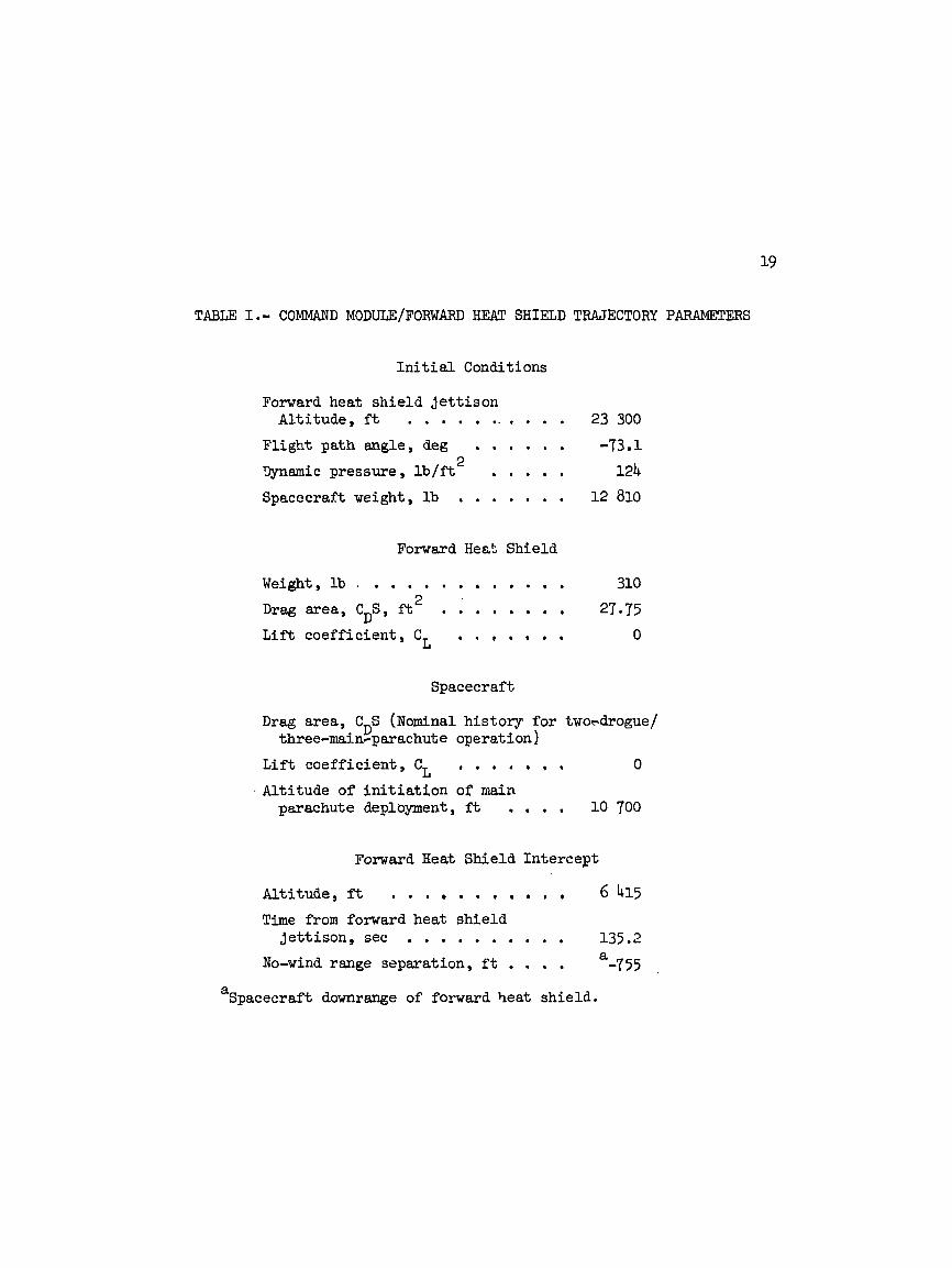
TABLE I.- COMMAND MODULE/FORWARD HEAT SHIELD TRAJECTORY PARAMETERS
Initial Conditions
Forward heat shield jettison Altitude, ft . . . • . .. . . . .
Flight path angle, deg
Dynamic pressure, lb/ft2
Spacecraft weight, lb
. . .
Forward Heat Shield
Weight, lb • • • • • • , • 2
Drag area, CDS' ft •••••
Lift coefficient, CL ' • • • • • t
Spacecraft
23 300
-73.1
124
12 810
310
27.75
0
Drag area, CDS (Nominal history for two~drogue/ three-main~parachute operation}
Lift coefficient, CL •••• • • • 0
· Altitude of initiation of main parachute deployment, ft • • • • 10 700
ForNard Heat Shield Intercept
Altitude, ft • • • • • • ' • • ' t
Time from forward heat shield jettison, sec
No-wind range separation, ft ••••
aSpacecraft downrange of forward ~eat shield.
6 415
135.2
a-755
19

20
./ ~F,.wanl heat shield loadi"g edge
Broken and damagt!d lines
70ft/sec
Two risers
----- ---Figure 11.- Results of f\h.'lard heat shield/suspension system impact test.

These tests shoved that the forward heat shield contacting the parachute could damage some of the S<l.Spension lines~ but would probably not cause a loss of riser legs.
Forward lteat shield/command module impact tests.- Using the suspendon line/riser test setup, two additional drop tests vi th the forward heat shield imracting the spacecraft were performed. In the first test, the forward heat shield impacted the spacecraft upper deck in the minus Y and minus Z bays , causing very light surface damage to the spacecraft , but severe da'l!lage tc. the forward heat shield. In the second test, the forward heat shie l_d impacted the spacecraft near the hatch, breaking the outer hatch window and gouging the ablator. Again, the forward heat shield vas severly damaged.
Based or. the impact tests and analysis, the worst-case damage which could be expected would occur if ... he forward heat shield : .mpacted the crew compartment heat shield window. There is a possibil::.ty toct both the heat shield window and inner window would be broken.
Forward heat shield/parachute canopy test.- A test in which a for~ ward heat shield vas dr0pped onto a parachute vas performed to assess the damage which .might result to the parachute canopy. To simulate the in ... flated main parachute, a 95-foot diame~er polyethylene balloon vas inflated to 0.2-inch of vaT.er (the dynamic pressure during steady-state descent) with the parachute placed over the balloon and the suspension lines weighted. By using a guide cable, the forward heat shield vas guided to impact the parachute canopy. The impact produced cutting, tearing, and burn-type damage. One parachute radial seam was broken, another vas cut , and six sails were damaged. If this type of damage had been experienced in flight, the parachute probably would have rem:rlned inflated providing a near-nominal drag effect.
Conclu~ions froffi forward heat shield investigations .... The forward heat shielrl was not the cause of the failure ·of the main parachute based on two separate sets of data. First, the television tape shows the forV3rd heat shield eml!rging from the clouds approximately 3 seconds prior to the anomaly. Second, the results of the suspension line and riser impact tests with the forwara heat shield show that substantial damage to the room-temperature vulcanizing material on the leading edge of the forward heat shield would have occurred had there been contact. The recovered forward heat shield did not have this type of damage. There vas no evidence of heat shield contact with the parachute.
Both the trajectory analysis and the television and observer data sltow that the for.,ard heat shield did come close to the spacecraft. The analysis predicts that, for future flights, probabili ty.-of-contact is less than 1 in 1000. In d.ddi tion, the tests of the forward heat shield impact.ing the suspensic.n and riser lines, the spacecrat~, and the canopy, indicate that, should contact occur, the resulting damage 'wuld not be catastrophic. Therefore, based on the low probability of contact, and the

23
acceptable damage should the heat shield contact the spacecraft and its parachute system, no corrective action is required.
Riser/Suspension Line Conn~ctor Links
One stud in ~ connector link assembly on the Apollo 15 recovered parachute failed. The failure was caused by stre ;s corrosion cracking, hydrogen embrittlement, or some unkno'W!l mechan.:sm. Stress corrosion is a possible cause because the high-strength steel (4130) used in the links is susceptible at high stress levels to cracking in salt water. Hydrogen embrittlement is a possibility because of the susce~tibility of the highstrength steel to cracking from dissolved hydrogen. Earlier in the Apollo program, studs which were not properly processed after plating failed because of hydrogen embrittlement.
Link testing.- Several tests were performed on the connector links. Tht. results are discussed in the following paragraphs:
Sustained-load test: Two link assemblies were sustain loaded in tension, axially along the studs, to a stress of 132 000 psi at the minor diameter of the stud threads. The test was to reveal the presence of hydrogen embri ttled material; however, the tested links had been exposed to salt water, and therefore, this test vas not sufficient to distinguish between delayed failure from salt-water immersion or hydrogen.
The first specimen failed 7.6 hours after load application. The fracture surface had approximately two~thirds of the cross sectional area at the stud shoulder exposed to a corrosive environment (probably sea water) prior to the start bf the test.
The second link specimen failed 48.9 hours after load application. This specimen did not have the large pre-corroded area observed on the first specimen; however, approximately 10 percent of the cross-section h&.d corrosion present. The sustained-load induced ... fracture area was duc.tile on both specimens.
Stress corrosion tes~s: Four studs from the recovered parachute links (lot U) were loaded to a stress of 132 000 psi in t~nsion at the minimum section of the studs. Three of these studs were notched, and the fourth specimen was tested in the original configuration. All four specimens survived 200 hours of s~stained load in air. After 200 hours, sea water was placed in contact with the notched area of two of the studs and the load was maintained for an additional 48 hours. The third notched specimen remained in sustained load as a control specimen. Although the sides of the notches exposed to salt water were highly corroded, no failure occurred. The unnotched specimen was removed after 200 hours of sustained load in air and inspected under 25-pover magnification for cracks
and none were observed. This unnotched stud was then remounted in a link assembly, torqued to 120 in-lb, which is twice specification level, and 'laced in sea water for 24 hours. The links ari studs were then air dried, disassembled, anci examined for cracks. No cracks were found.
Eight additiQnal studs were torqued to 200 in-lb in order to simulate the effect of tolerance buildup of stresses at specification torque levels. Two studs failed during exposure to sea water, thus confirming the possibility of generating salt-water-induced stress corrosion cracking if the parts are within drawing limits.
Tensile tests: Two lot T studs, which had not been exposed to salt water, were placed under load as studs to a stress level of 132 000 psi , as computed for the minor diameter of the stud threads. This stress was maintained for 200 hours in an air environment. The stress was maintained while sea water was placed in contact with the stressed threads. After 48 hours, the sea water was allowed to dry and the specimen was maintained under load for an additional 24 hours. No cracks were found when the speci~ men was examined under 25-power magnification. Both specimens were then pulled to failure in tension, after exhibiting yielding, at 254 000 psi (normal notch strengthening for this material]. No evidence of pre-existing flaws or corrosion was found on the fracture surface.
A total of ten studs (two each from: a pack life parachute, lot U that had not been flown, and recovered parachutes used on Apollo 10, 12, and 13) were loaded in tension to 132 000 psi as calculated for the minor diameter of the threads. No failures occurred in the accumulated 150 hours of air exposure test time on each specimen.
Two other tests were performed to provide base~line data on stud failures. An Apollo 10 stud was purposely charged with eydrogen and placed under a net section stress load of 132 000 psi. The stud failed in 30 minutes and thus validated the hydrogen embrittlement screening test. The second test used lot R links that had originally been rejected due to hydrogen e~brittlement. These links were tested to 132 000 psi for 200 hours without failure, indicating that the hydrogen embrittlement characteristics had decayed.
The results of metallurgical examinations and these tests support the following conclusions:
1. Physical evidence for hydrogen-inducea delayed failures of lot U and lot T studs does not now exist but, due to the long elapsed time since plating, hydrogen-induced failure cannot be ruled rut.
2. Sea water does not induce cracks at the times and nomina] stress levels expected. although general rusting of exposed steel occurs rapidly. Stress corrosion cracks can be induced by exposure to salt water at stress levels higher than those expected for a nominal 60 in~lb torque.

3. For the failed studs, the flaws probably occurred after the plating operation.
25
Studs exposed to hypergolic propellants are to be tested in order to date:rrr,ine if propellant exposure could have caused the observed flaws.
Pull tests: A series of connector link pull tests were conducted. A.'1. Apollo link which had been preloade.d (nuts torqued} for more than 2 years with no salt water contact was pull tested to destruction (12 700 pounds) to provide a strength r6ference. Two special high-strength studs were fabricated to allow pull testing of the link end plates. However, the high-strength studs failed at a load of 12 850 pounds, and the end pl~tcs remained intact, verifying that the Apollo link studs are the weakest structural members.
The recovered Apollo 15 connector link with the separated stud was fitted with a riser and suspension lines and pull tested to eval11ate its capability in the three-nut configuration. The link had failed in the stud thread and the stud had a shoulder remaining in the end plate which could carry load. This link was successfully subjected to two complete flight load cycles, then the load was increased to 5000 pounds (which cor~ responds to canopy ultimate strength) and successfully held for 2 minutes. These tests demonstrated that the stud failure could have occurred prior to parachute deployment. A final test was made with one end plate removed, simulating a tensile failure of one stud at the shoulder, or t1·ro sheared studs • This link failed at 1300 pounds , a value below the opening loads but higher than the steady-state loads.
Reliability and guality assurance records review • .- A review was made of the manufacturing and inspection history records of the parachute li-'lk assembly manufactured by Northrop Ventura •. Records were researched at North American Rockwell, Downey, California; Metal Surfaces, Inc. , Bell Gardens, California; and Northrop Ventura, Thousand Oaks, California.
The records show that the parts for Apollo 15 (lot Q plates, and lot U studs) and Apollo 16 (lot W plates and studs) were properly processed in accordance with the latest revision of the Northrop plating specification.
One significant item disclosed by the review was that lot R studs which should have been scrapped were accepted and installed in flight parachutes. Lot R studs were flown in one parachute on Apollo 14, and were installed in a parachute to be used for future flight.
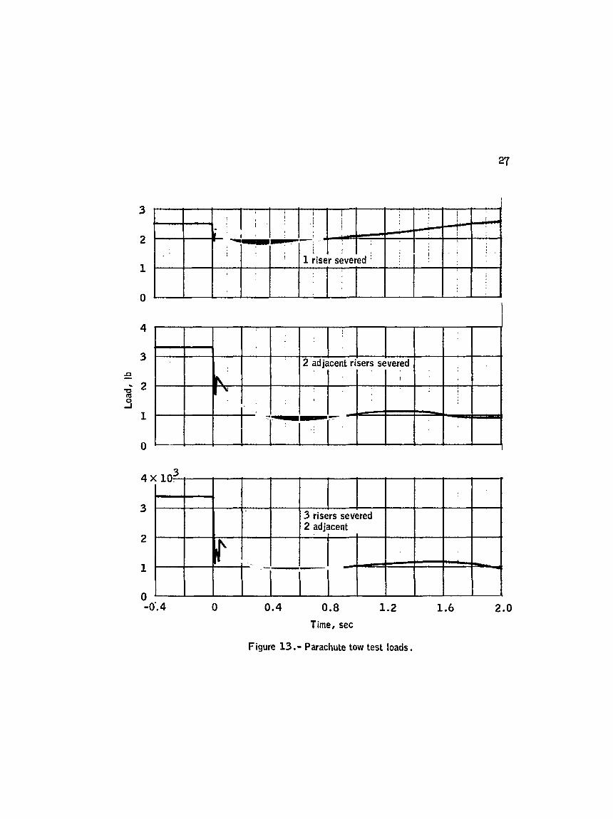
Parachute tow tests.- A series of ground tow tests was conducted to evaluate the characteristics of the inflated parachute and riser load re~ sponse resulting from severing one, two, and three riser legs of a fully inflated main parachute. Inflation was obtained b:r towing the parachute

into the wind. When the canopy was fully inflated and stable, selected risers were pyrotechnically severed. Individual riser leg loads, total riser load, and photographic documentation were obtained.
When one of the six r:i.ser legs was severed, the canopy remained fully inflated and, in approximately 2 seconds, exhibited full riser load. When two adjacent riser legs were severed, the canopy collapsed but did continue to provide a drag force of approximately one-third the fully inflated value. Three risers were severed in the third test; two were adjacent and the third was separated from them by a good riser leg. When the risers were severed, the canopy collapsed, with the portion opposite the severed risers holding air for several seconds. The load histories for each of the three tests are shown in figure 13. The initial load drop for the one-, two-, and three-riser test was 600, 1700, and 2300 lb, respectively.
These tests indicated that the Apollo main parachute will remain fully inflated and provide normal drag with one of its six riser legs severed. When two or more adjacent riser legs are severed, the canopy will collapse, and lose at least two-thirds of its load-carrying capability.
Conclusions from connector link investigations.- The failed link on the recovered parachute implies the possibility of a similar occurrence on the failed parachute. However, the parachute tow tests indicate that a single link failure would not have caused the load change (approximately 1300 pounds) determined from the spacecraft data. Although the link failure is not believed to have caused the parachute anomaly, a complete records review and a materials test program were performed to determine the cause of the flaws. The records show that the Apollo 15 lot links were processed in accordance with all requirements. The link tests showed that the broken link can carry the flight loads (in the case of Apollo 15 type break) • The available evidence cannot rule out either hydrogen em ... brittlement or salt-water-induced stress corrosion at higher ... than-expected stress levels as the possible cause of the failure. In fact, the cause of the flaw is not known.
Command r!Jodule Reaction Control System
The command module reaction control system was considered as a possi ... ble cause of the anomaly for the following reasons:
a. The propellant depletion firing terminated 3,5 seconds before the spacecraft rates gave evidence of a major disturbance. The excess fuel expulsion which followed the depletion firing was still in progress at the time of failure
b. The damaged parachute held a position generally above the minus Y roll engines while the fuel expulsion was in progress.
27
'·.· I . ! ! __L
2 .I JJ;~d:±::t!!:O !
t---+---...11- ~-..... -:.' -&2·----:'. 1
0
4
1
0
4X 3 10~
2
1
0 -0'.4
:
It\. "-i
t 0
' I I '
1 riser severed :
'
2 adjacent risers severed !
: ; '
' :
~T~--~~-" . I . .
3 risers severed 2 adjacent
--n-, 0.4 0.8 1.2 1.6 2.0
Time, sec
Figure 13.- Parachute tow test loads.
c. Burning fuel can cause damage to the risers, suspension lines, or parachute canopy.
d. Evidence of melting was found on the Dacron protective covering of the fabric riser and the connector links on the recovered parachute assembly.
S~stem Operation.- Both command module reaction control systems were activated normally at 294:0[:14. Both systemz were used during entry as opposed to previous missions where one system was turned off prior to entry. System performance during the controlled portion of entry was nominal as verified by pressure and temperature data and from spacecraft rates produced by commanded engine firings.
The command module reaction control system control firings were terminated normally at 295:06:44 when the systems were electrically disabled. At this point in the mission, the engines had been fired approximately 680 times and the total firing time was about 160 seconds • The propellant usage had been 20 pounds of fuel and 36 pounds of oxidizer, divided equally between the two systems. Propellant consumption was established by pressure, temperature, and volume calculations and confirmed by the summation of the engine firing times. Usable propellant remai~ing at 295:06:44, prior to the start of the depletion firing, was 30 pounds of fuel and 53 pounds of oxidizer in each system for a total of 60 pounds of fuel and 106 pounds of oxidizer. Total propellant remaining, including the trapped propellants , was 69 pounds of fuel and 120 pounds of oxidizer.
The command module reaction control system depletion firing was manually initiated at 295:08:22. During this firing, the two systems were interconnected by opening squib valves between the helium manifolds, the fuel manifolds, and the oxidizer manifolds •. The engine valves on all but the two plus pitch engines were also opened using the direct coils. System pressures indicated that the depletion firing was normal with oxidizer depletion at 295:09:10. Fuel depletion followed 4.7 seconds later. These times were. confirmed by calculations using the propellant remaining prior to the firing, and a mixture ratio and propellant flow rate commensurate with steady-state firing from 10 engines. Between the time of oxidizer depletion and fuel depletion, about 7 pounds of raw fuel were being expelled.
The command module reaction control system line purge operation was manually idtiated at 295:09:22. This operation opened four squib valves that enabled the helium gas to bypass the propellant tanks and purge the residual or trapped propellants from the system manifold lines. Regulated helium pressure and helium source pressure data verified a normal purge operation. At 295:09:25 and 295:09:28, colored clouds were seen coming from the spacecraft. This is normal and is caused by the expulsion of unburned oxidizer through the engines by the purge operation. Unburned fuel is also often seen about this time in the form of a white cloud.

29
Postflight testing of the command module reaction control syst.:=!m showed it to be in normal working order. Testing included leak checks of the propellant tank bladders, engine valve leak tests, engine valve signature traces to verifY proper opening characteristics, and electronic tests to verify the electrical wiring and terminal board connections.
Command module reaction control system fuel expulsion tests.- Two tests were performed to investigate the potential effects of a raw fuel expulsion on the parachutes:
The first test was a feasibility demonstration to determine if fuel sprayed on the parachute risers and suspension lines would burn, assuming that there could be an ignition source. A simple nozzle was used to sprey raw fuel into a 30 ft/sec air stream and onto a sample of the riser and suspension lines, part of which was surrounded by a Dacron bootie. Hotwire ignition sources were imbedded in the bootie and riser to sim\uate an inflight ignition source. These tests demonstrated that, above certain threshold fuel concentration levels, the fuel on the booties would burn in a wick-like mannsr. This resulted in riser and suspension line failures due to melting of the nylon material.
rhe second test consisted of firing a command mouule reaction control system engine followed by fuel cold flow (simulated fuel expulsion). It was performed to investigate the effects of cold flowing raw fuel through a hot engine. For these tests, a reaction control srstem engine and a minus-pitch nozzle extension wera mounted horizontall~ in an ambient test cell. There was no attempt to simulate the relative air velocitr surrounding a descending command module. T.1e test firings consisted of a series of hot firings of 10 to 45 seconds in duration, each followed by a 5~second fuel cold flow (about 0. 6 pound of fuel) • In every case, the rav fuel ex.pulsion sequence produced burning outside of the engine. Burning fuel vapor, burning fuel droplets, and some unburned fuel were observed during these tests. The flame front existed up to 8 feet from the engine exit plane and unburned fuel was sprayed up to lO.feet from the engine and then ignited by burning droplets.
Conclusions from reaction c~. system investigations.- As a result of these tests, the hazard of a raw fuel expulsion was demonstrated. In addition, since the failed parachute was positioned over the roll engines for the time period just prior to the anomaly, the effects noted in the second test were, most likely, the cause of the Apollo 15 para~hute failure.
CONCLUSIONS
The analysis of the data and results of the special tests lead to the following conclusions:
30
a. The most probable cause of the anomaly was the burning of raw fuel (monomethyl hydrazine) being expelled during the latter portion of the depletion firing and this resulted in exceeding the parachute-riser and suspension-line temperature limits.
b. The forward heat shield passed extremely close to the command module during the descent phase; however, at the time of the anomaly, the heat shield was 700 feet below the command module.
c. Impact of the forward heat shield on the parachute risers, suspension lines, canopy, or spacecraft will not cause catastrophic damage.
d. The failure of a single connector link will not cause a main parachute to fail.
e. The flaw observed in the recovered parachute connector link probably occurred after the plating operation, and could be due either to saltwater-induced stress corrosion or hydrogen embrittlement.
CORRECTIVE ACTION
Corrective actions for the reaction control syst~ include landing with the propellants onboard for a normal landing and biasing the propellant load to provide a slight excess of oxidizer. Thus, for the lowaltitude abort land landing case, burning the propellants while on the parachutes will sut~ect the parachutes to some acceptable oxidizer damage but will eliminate the dangerous burning fuel condition. In addition, the time delay which inhibits the rapid propellant dump is being changed from 42 to 61 seconds. This will provide more assurance that the propellant will not have to be burned through the reaction control system engines in the event of a land landing.
The design of the suspension line connector links has been modified. to preclude the development of high stress levels due to torque levels and to reduce the uncertainty of loads due to tolerance buildup. The link material has been changed to Inconel 718 to eliwinate the requirement for plating and, therefore, the possibility of hydrogen embrittlement. In addition, the link stud threads are rolled rather than machined to improve metallurgical properties of the material, and the studs are subjected to a proof test designed to screen flaws which could subsequently propagate under salt water exposure.