MS3X/V3.0 Hardware Manual - Megasquirt UK Official...
212
MS3X/V3.0 Hardware Manual Megasquirt-3 Product Range MS3 1.3.x DRAFT Dated: 2014-08-29 This version of the documentation applies to: • MS3 on a V3.0 mainboard with MS3X as shown above running firmware MS3 1.3.x Does not apply to other Megasquirt products or other firmware versions. (c) 2014 James Murray
Transcript of MS3X/V3.0 Hardware Manual - Megasquirt UK Official...

MS3X/V3.0 Hardware Manual
Megasquirt-3 Product RangeMS3 1.3.x
DRAFT Dated: 2014-08-29
This version of the documentation applies to:
• MS3 on a V3.0 mainboard with MS3X as shown above running firmware MS3 1.3.x
Does not apply to other Megasquirt products or other firmware versions.
(c) 2014 James Murray

MS3X/V3.0 Hardware Guide
Table of Chapters1: Introduction.............................................................................................................................82: Megasquirt System Hardware..............................................................................................103: Wiring...................................................................................................................................124: Fuel System..........................................................................................................................525: Ignition System - fundamentals............................................................................................656: Ignition system - specific operating modes..........................................................................987: Throttles..............................................................................................................................1698: Optional Hardware.............................................................................................................1709: Example wiring...................................................................................................................17010: Further information...........................................................................................................17811: Appendix A Schematics....................................................................................................17912: Appendix B: junkyard guide to finding EDIS....................................................................19313: Appendix C: V3.0 Board Assembly..................................................................................19814: Revision history................................................................................................................212
(c) 2014 James Murray 2014-08-29 Page 2/212

MS3X/V3.0 Hardware Guide
Contents1: Introduction.............................................................................................................................8
1.1 Emissions and disclaimer................................................................................................81.2 Required tools..................................................................................................................81.3 How to use this manual....................................................................................................81.4 Scope of advice with MS3X.............................................................................................9
2: Megasquirt System Hardware..............................................................................................102.1 Overview........................................................................................................................102.2 Megasquirt Installation...................................................................................................102.3 Wiring Harness and fuses..............................................................................................112.4 Crank / Cam Inputs........................................................................................................112.5 Sensor Inputs.................................................................................................................112.6 Outputs...........................................................................................................................112.7 Tuning interface..............................................................................................................11
3: Wiring...................................................................................................................................123.1 Best Practices................................................................................................................12
3.1.1 Wire and connector choice.....................................................................................123.1.2 Soldering or crimping..............................................................................................123.1.3 Re-pinning the DB37..............................................................................................123.1.4 Fusing.....................................................................................................................123.1.5 4-pin relay pin-out note...........................................................................................123.1.6 Relay and accessory power routing.......................................................................12
3.2 Grounding (Earthing) Schemes.....................................................................................133.3 Core Wiring Diagram......................................................................................................14
3.3.1 Optional Connections.............................................................................................143.3.2 Additional internal inputs/outputs............................................................................15
3.4 Inputs..............................................................................................................................203.4.1 Crank and Cam Tach inputs...................................................................................203.4.2 MAP (Manifold Absolute Pressure) sensor.............................................................203.4.3 IAT/MAT (Intake/Manifold Air Temperature) sensor................................................213.4.4 CLT (Coolant Temperature) sensor........................................................................243.4.5 TPS (Throttle Position Sensor)...............................................................................243.4.6 O2 (Oxygen) Sensor / Lambda Sensor..................................................................253.4.7 MAF (Mass Air Flow) Sensor..................................................................................273.4.8 Flex / Switch input...................................................................................................323.4.9 Spare Analog (ADC) inputs.....................................................................................333.4.10 Switch inputs.........................................................................................................333.4.11 B/LD boot jumper..................................................................................................343.4.12 CAN comms..........................................................................................................353.4.13 Knock sensor........................................................................................................353.4.14 Realtime clock......................................................................................................383.4.15 PT4 input / output.................................................................................................393.4.16 Speed sensor inputs.............................................................................................39
3.5 Outputs...........................................................................................................................393.5.1 Fuel Injector outputs...............................................................................................39
(c) 2014 James Murray 2014-08-29 Page 3/212

MS3X/V3.0 Hardware Guide
3.5.2 Ignition outputs.......................................................................................................403.5.3 Fuel pump output....................................................................................................403.5.4 Idle valve.................................................................................................................403.5.5 Tacho output...........................................................................................................463.5.6 Mid current PWM / relay output..............................................................................46
3.6 Bench test wiring............................................................................................................483.6.1 Minimal connection.................................................................................................483.6.2 JimStim connection.................................................................................................483.6.3 V10 and V12 support (DIY mods)...........................................................................49
4: Fuel System..........................................................................................................................524.1 Introduction....................................................................................................................52
4.1.1 Existing EFI Vehicle................................................................................................534.1.2 Retro-fit EFI Vehicle................................................................................................53
4.2 Single Fuel pump...........................................................................................................534.3 Low pressure / high pressure - twin pump.....................................................................534.4 Wiring the Fuel Pump.....................................................................................................544.5 Fuel Line.........................................................................................................................544.6 Fuel filter.........................................................................................................................554.7 Fuel Pressure Regulator................................................................................................554.8 Injector installation.........................................................................................................564.9 Fuel Rails.......................................................................................................................564.10 Fuel Injectors................................................................................................................56
4.10.1 Injector Size..........................................................................................................564.10.2 Injector Impedance and wiring..............................................................................584.10.3 Staged injection....................................................................................................634.10.4 More wiring examples...........................................................................................64
5: Ignition System - fundamentals............................................................................................655.1 Safety Notes...................................................................................................................655.2 Crank and Cam tach inputs...........................................................................................65
5.2.1 Coil Negative Input.................................................................................................665.2.2 VR (magnetic) sensor input....................................................................................675.2.3 Hall sensor input.....................................................................................................685.2.4 Hall sensor input (built-in pull-up)...........................................................................725.2.5 Gear-tooth sensor input..........................................................................................745.2.6 GM LS 24X crank/cam sensors..............................................................................745.2.7 GM LS 58X crank/cam sensors..............................................................................745.2.8 Optical sensor.........................................................................................................755.2.9 Distributor points input............................................................................................755.2.10 Combined Ignition module (TFI, EDIS, HEI, GMDIS)..........................................765.2.11 Nissan CAS...........................................................................................................765.2.12 4G63 / 6G72.........................................................................................................785.2.13 Mitsubishi CAS with aftermarket disc...................................................................785.2.14 Cam sensor input..................................................................................................78
5.3 Ignition outputs...............................................................................................................805.3.1 Building ignition outputs..........................................................................................805.3.2 Logic coils...............................................................................................................815.3.3 Amplifiers (ignitor, power transistor, ignition module).............................................88
(c) 2014 James Murray 2014-08-29 Page 4/212

MS3X/V3.0 Hardware Guide
5.3.4 High current coils....................................................................................................925.3.5 CDI modules (e.g. MSD, Crane etc.)......................................................................945.3.6 Mazda Rotary ignition wiring..................................................................................955.3.7 Toyota DLI ignition wiring........................................................................................96
6: Ignition system - specific operating modes..........................................................................986.1 Coil negative for fuel only.............................................................................................1006.2 Distributor pickup.........................................................................................................101
6.2.1 Traditional vac/mech distributor............................................................................1016.2.2 Rotor / Output phasing - all distributor installs......................................................1046.2.3 Distributor with hall/optical 'trigger return'.............................................................1056.2.4 Distributor with basic crank trigger.......................................................................1076.2.5 Distributor with crank trigger wheel......................................................................107
6.3 Ford TFI........................................................................................................................1076.4 GM HEI7.......................................................................................................................1086.5 GM HEI8.......................................................................................................................1106.6 Dual Sync Distributor....................................................................................................1116.7 Ford EDIS.....................................................................................................................111
6.7.1 System components..............................................................................................1116.7.2 ECU wiring............................................................................................................1126.7.3 Module wiring........................................................................................................1126.7.4 36-1 trigger wheel and VR sensor........................................................................1146.7.5 Checking the timing..............................................................................................1186.7.6 Optional cam sensor.............................................................................................118
6.8 GM DIS (for reference only).........................................................................................1196.9 Toothed Wheel..............................................................................................................119
6.9.1 Wheel combinations.............................................................................................1206.9.2 Terminology notes.................................................................................................1216.9.3 Wheel naming.......................................................................................................1216.9.4 Retrofit install........................................................................................................1226.9.5 Existing install.......................................................................................................1236.9.6 Missing tooth crank wheel....................................................................................1236.9.7 Missing tooth cam wheel......................................................................................1256.9.8 Missing tooth crank wheel and single tooth cam wheel.......................................1256.9.9 Missing tooth crank wheel and polled cam wheel................................................1286.9.10 Nippondenso CAS..............................................................................................1326.9.11 Non-missing tooth crank wheel with one cam tooth...........................................1376.9.12 Mitsubishi CAS with aftermarket disc - single coil / wasted spark.....................1406.9.13 Mitsubishi CAS with aftermarket disc - coil-on-plug...........................................1416.9.14 Other wheel arrangements.................................................................................1426.9.15 Example: Ford Zetec..........................................................................................142
6.10 Neon/420A.................................................................................................................1436.11 36-2+2 (NGC).............................................................................................................1456.12 36-2-2-2......................................................................................................................1466.13 Miata 99-05................................................................................................................1466.14 Subaru 6/7..................................................................................................................1476.15 6G72...........................................................................................................................1476.16 IAW Weber.................................................................................................................148
(c) 2014 James Murray 2014-08-29 Page 5/212
MS3X/V3.0 Hardware Guide
6.17 Mitsubishi CAS 4/1.....................................................................................................1496.18 Mitsubishi 4G63 (and Miata)......................................................................................1496.19 Twin trigger.................................................................................................................1516.20 Chrysler 2.2/2.5..........................................................................................................1526.21 Renix 44-2-2 (66-2-2-2).............................................................................................1526.22 Suzuki Swift................................................................................................................1526.23 Suzuki Vitara 2.0........................................................................................................1536.24 Daihatsu 3cyl..............................................................................................................1536.25 Daihatsu 4cyl..............................................................................................................1536.26 VTR1000....................................................................................................................1536.27 Rover#1......................................................................................................................1546.28 Rover#2......................................................................................................................1546.29 Rover#3......................................................................................................................1546.30 GM7X.........................................................................................................................1556.31 QR25DE.....................................................................................................................1556.32 Honda RC51..............................................................................................................1556.33 GM LS1 (24X)............................................................................................................1556.34 GM LS2 (58X)............................................................................................................1576.35 YZF1000.....................................................................................................................1586.36 HD 32-2......................................................................................................................1596.37 Miata 36-2..................................................................................................................1596.38 Fiat 1.8 16V................................................................................................................1596.39 Optispark....................................................................................................................1596.40 Nissan SR20..............................................................................................................1616.41 Nissan RB25..............................................................................................................1626.42 Honda Acura V6.........................................................................................................1636.43 VQ35DE.....................................................................................................................1646.44 Jeep 2000..................................................................................................................1646.45 Jeep 2002..................................................................................................................1646.46 Zetec VCT..................................................................................................................1656.47 Flywheel tri-tach.........................................................................................................1656.48 2JZ VVTi.....................................................................................................................1666.49 Honda TSX/D17.........................................................................................................1666.50 Mazda6 2.3 VVT........................................................................................................1666.51 Viper V10 (gen 2).......................................................................................................1676.52 Viper V10 (gen 1).......................................................................................................1676.53 Honda K24A2.............................................................................................................167
7: Throttles..............................................................................................................................1698: Optional Hardware.............................................................................................................170
8.1 Expansion boards........................................................................................................1709: Example wiring...................................................................................................................170
9.1 Sequential fuel and spark............................................................................................1709.1.1 Inline 4 : 1-3-4-2....................................................................................................1709.1.2 V6 : 1-6-5-4-3-2....................................................................................................1739.1.3 Inline 6 : 1-5-3-6-2-4.............................................................................................1749.1.4 V8 : 1-8-4-3-6-5-7-2..............................................................................................1759.1.5 V8 : 1-8-7-2-6-5-4-3..............................................................................................176
(c) 2014 James Murray 2014-08-29 Page 6/212
MS3X/V3.0 Hardware Guide
9.2 Nitrous..........................................................................................................................1779.3 Other examples............................................................................................................178
10: Further information...........................................................................................................17811: Appendix A Schematics....................................................................................................17912: Appendix B: junkyard guide to finding EDIS....................................................................193
12.1 North America - EDIS4...............................................................................................19312.2 Europe - EDIS4..........................................................................................................19412.3 Europe - EDIS6..........................................................................................................19612.4 Europe - EDIS8..........................................................................................................19612.5 Europe - 36-1 trigger disc..........................................................................................19612.6 Europe - VR sensor...................................................................................................19712.7 World - Coilpack(s).....................................................................................................197
13: Appendix C: V3.0 Board Assembly..................................................................................19813.1 Introduction................................................................................................................19813.2 Build choices..............................................................................................................19813.3 Assembly....................................................................................................................19913.4 Testing Stage.............................................................................................................206
14: Revision history................................................................................................................212
(c) 2014 James Murray 2014-08-29 Page 7/212

MS3X/V3.0 Hardware Guide
1: IntroductionThe MS3X/V3.0 is an ECU based on Megasquirt-3 technology, consisting internally of an MS3 card and an MS3X expansion card installed on a through-hole DIY V3.0 mainboard. This manual covers MS3X/V3.0 specific installation details and should be used in conjunction with the general Megasquirt-3 Setting up and Megasquirt-3TunerStudio reference manuals.
1.1 Emissions and disclaimerAll parts are sold for OFF ROAD RACE-ONLY ground-vehicle use only, or vehicles that pre-date any federal and state emissions control requirements. Aftermarket EFI/EMS systems are not for sale or use on pollution controlled vehicles. Alteration of emission related components constitutes tampering under the US EPAguidelines and can lead to substantial fines and penalties. Your country/state/district may also have specific rules restricting your tampering with your vehicle’s emissions system.
Race parts are inherently dangerous and may cause injury or damage if improperly modified or altered before use. The publishers of this manual will not be held liable for and will not pay you for any injuries or damage caused by misuse, modification, redesign, or alternation of any of our products. The publishers of this manual will not be held in any way responsible for any incidental or consequential damages including direct or indirect labor, towing, lodging, garage, repair, medical, or legal expense in any way attributable to the use of any item in our catalog or to the delay or inconvenience caused by the necessity of replacing or repairing any such item.
1.2 Required toolsTuning laptop
Stroboscopic timing light
Multi-meter (volts, ohms)
Screwdrivers
Wire cutters
Terminal crimpers
Soldering iron and solder
Heat-shrink tubing
Fire extinguisher
Although not essential, the following are highly recommended:
Oscilloscope or scope-meter or soundcard scope
Test light
Power probe
1.3 How to use this manualCustomers new to EFI are advised to read all of sections 1-5 as these cover some fundamental concepts and give an overview of how to connect up the various EFI components.
More experienced customers can likely skim through sections 1-5.
Section 3.3 is the external wiring diagram, you should print that out.
Section 6 covers the many different tach trigger input schemes (wheel decoders) that exist to support numerous OEM trigger wheel patterns. Find the section that is appropriate for your engine and read that one.
(c) 2014 James Murray 2014-08-29 Page 8/212

MS3X/V3.0 Hardware Guide
This guide includes a number of notes which are indicated as follows:
This symbol indicates an “Information” note.
This symbol indicates a “Caution” note.
This symbol indicates a “Warning” note.
Installing or tuning your Megasquirt incorrectly can potentially cause damage to your engine, the Megasquirt or external hardware. Warning notes indicate specific areas where you need to exercise extreme care.
Do not rely on these warnings as your only criteria for taking care !
For additional help and support, visit the website www.msextra.com
1.4 Scope of advice with MS3XThis manual is written for the MS3X/V3.0 with MS3X board. It is assumed the MS3X inputs and outputs will be used where possible as these are easy to use without DIY.
The MS3X card is an input/output board for the MS3 and features:
8 hi-z injector drivers (or low-z with external resistors)
8 logic level spark outputs
6 mid current outputs for driving small solenoids or relays (on/off or PWM)
3 analogue inputs (0-5V)
4 switch inputs
Flex-fuel sensor input
Cam sensor input
Generally, instructions for DIY modifications of the mainboard for additional inputs and outputs are not discussed - see the MS3/V3.0 manual if desired.
(c) 2014 James Murray 2014-08-29 Page 9/212
MS3X/V3.0 Hardware Guide
2: Megasquirt System Hardware
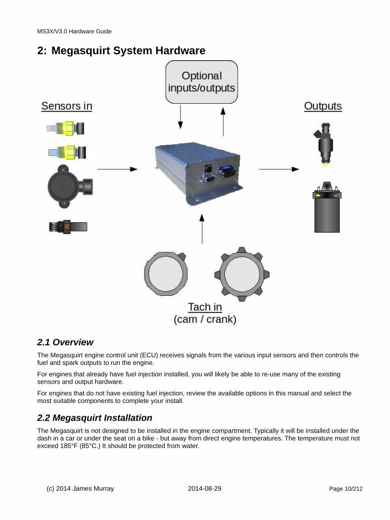
2.1 Overview The Megasquirt engine control unit (ECU) receives signals from the various input sensors and then controls the fuel and spark outputs to run the engine.
For engines that already have fuel injection installed, you will likely be able to re-use many of the existing sensors and output hardware.
For engines that do not have existing fuel injection, review the available options in this manual and select the most suitable components to complete your install.
2.2 Megasquirt InstallationThe Megasquirt is not designed to be installed in the engine compartment. Typically it will be installed under the dash in a car or under the seat on a bike - but away from direct engine temperatures. The temperature must not exceed 185°F (85°C.) It should be protected from water.
(c) 2014 James Murray 2014-08-29 Page 10/212

MS3X/V3.0 Hardware Guide
2.3 Wiring Harness and fusesThe Megasquirt can be supplied with a "pigtail" wiring harness to form the basis of your own wiring.
2.4 Crank / Cam InputsThe Crank and Cam sensors provide the Megasquirt with engine position information which is critical for ignition timing. Fuel-only installs will often take a signal from an existing inductive ignition coil.
2.5 Sensor InputsThe sensor inputs provide the ECU with information about current engine operating conditions and are used to calculate the fuel and spark outputs.
The primary inputs are MAP sensor, MAT sensor, CLT sensor, TPS and O2 input.
2.6 OutputsBased on the crank/cam and sensor inputs the Megasquirt calculates the required fuel and spark outputs.
2.7 Tuning interfaceThe Megasquirt uses either:
a) an RS232 interface for tuning. This is provided as a standard DB9 serial connector. Your computer will likely require a USB-serial adapter also - adapter cables based on the FTDI chipset are recommended. Some customers have reported unreliability with Prolific based cables.
b) a built in USB-serial interface for tuning. This is based on the FT232 chipset from FTDI.
Do not connect both interfaces at the same time.
Megasquirt also has CAN communications for connection to add-on modules or dashes.
(c) 2014 James Murray 2014-08-29 Page 11/212

MS3X/V3.0 Hardware Guide
3: WiringA main step in your Megasquirt installation is connecting up the wiring. Be sure to follow the guidance here to avoid common mistakes that will often lead to problems.
3.1 Best Practices
3.1.1 Wire and connector choiceFor many first-time users, it may be tempting to re-use old connectors and wiring. While this may sometimes be cost-effective, beware of false economy. Using fresh connectors and suitable automotive grade wiring can save many a headache. Be particularly aware of using wire or components that are not temperature rated high enough, engines get HOT and the insulation on sub-standard wires can melt or degrade leading to erratic connections or short circuits. All components must be rated for 105°C / 220°F as a minimum.
There are many suppliers dedicated to supplying the required items to construct wiring harnesses.
3.1.2 Soldering or crimpingThis is mainly down to personal choice, some installers prefer a soldered joint, others swear that crimped connections are superior. The key task is to make a reliable connection.
In your wiring harness you will need to ensure that all joints are effective both electrically and mechanically. Always test by tugging on the wires to ensure that they are not loose. Use heat-shrink tubing over connections to insulate them and prevent shorts.
Don't even think about using scotch blocks - they are bad enough for installing a radio or trailer plug!
3.1.3 Re-pinning the DB37Optionally, to create the smallest wiring harness possible, the DB37 connector in a pre-made loom can have anyunused spare wires removed.
3.1.4 FusingIt is required that the system be fused - as shown in the general wiring diagram. Remember that an automotive battery is capable of supplying hundreds of amps into a short circuit which can easily melt wires or start a fire. Appropriate fuses can help reduce this risk and save component damage.
If there is a risk of the connections becoming damp then it can be worth applying petroleum jelly (e.g. Vaseline) to the connections to slow the corrosion.
3.1.5 4-pin relay pin-out noteBe aware that there are two incompatible "standards" for four-pin automotive relays. Mixing them up will usually cause a short-circuit in your wiring harness. The type where pin 85 is opposite 86 is preferred as this is the same as 5-pin relays.
3.1.6 Relay and accessory power routingAny relays, solenoids or lamps operated by the Megasquirt must only be powered when the Megasquirt is on. Typically it is easiest to take their power from the "fuel pump relay" so they are only powered when the engine isrunning. Miswiring accessories can cause power to backfeed into the Megasquirt causing unexpected behavior such as running-on.
(c) 2014 James Murray 2014-08-29 Page 12/212

MS3X/V3.0 Hardware Guide
3.2 Grounding (Earthing) Schemes
Implementing a correct grounding scheme is critical to a successful Megasquirt install.
Connecting sensors to the wrong ground, using corroded ground points or dubious original wiring are sure-fire ways to give you a headache.
There are two key rules:
1. All sensors must ground at the Megasquirt
2. Ground the Megasquirt at the engine block/head using both available ground wires.
Reasoning:
When a current flows through a wire there is always a voltage drop, the bigger the current, the bigger the drop (this is ohm's law.) During cranking there is a very large current flowing through the ground strap from battery to engine and perhaps a few volts may be dropped across it. Even during running, a number of amps will flow through the Megasquirt grounds to the engine.
The sensors (coolant, air temp, throttle position, wideband, tach input) all use low current, low voltage signals. The Megasquirt measures the voltage from the sensor and converts it into a temperature, position etc. reading. If that sensor is grounded to anything other than the Megasquirt itself, then that input voltage will be altered by any external voltage drops. For a sensitive measurement such as AFR (lambda) this can be a real problem. All good wideband controllers offer a high-current ground (connects to engine) and a sensor/signal ground (connects to Megasquirt.)
Tach input (e.g. crank, cam sensors) will be even worse - they can show false or missed teeth and cause sync-loss due to the ground voltage difference.
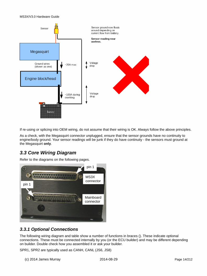
The following two diagrams illustrate good and bad wiring schemes showing where the troublesome voltage drops are created and how that would cause sensor readings to be garbage.
(c) 2014 James Murray 2014-08-29 Page 13/212
MS3X/V3.0 Hardware Guide
If re-using or splicing into OEM wiring, do not assume that their wiring is OK. Always follow the above principles.
As a check, with the Megasquirt connector unplugged, ensure that the sensor grounds have no continuity to engine/body ground. Your sensor readings will be junk if they do have continuity - the sensors must ground at the Megasquirt only.
3.3 Core Wiring DiagramRefer to the diagrams on the following pages.
3.3.1 Optional ConnectionsThe following wiring diagram and table show a number of functions in braces (). These indicate optional connections. These must be connected internally by you (or the ECU builder) and may be different depending on builder. Double check how you assembled it or ask your builder.
SPR1, SPR2 are typically used as CANH, CANL (JS6, JS8)
(c) 2014 James Murray 2014-08-29 Page 14/212
MS3X connector
Mainboard connector
pin 1
pin 1

MS3X/V3.0 Hardware Guide
SPR3, SPR4 have no standard function and are spare
IAC1A, IAC1B, IAC2A, IAC2B are typically connected to the stepper outputs from the MS3 card.
FIDLE as standard is only suitable for switching a relay. To use it with a 2-wire PWM idle valve the transistor on the mainboard needs uprating. This is covered later.
IGN is typically connected internally to a high-current ignition driver (BIP373)
Installs with MS3X will typically use the MS3X outputs for sequential logic spark, sequential fuel and idle valve.
All of the GND pins are connected internally, the wiring here is recommended.
Extra high current fuel pumps may benefit from their own relay for minimal voltage drop.
3.3.2 Additional internal inputs/outputsThe following pin connections are available within the ECU, instructions on using them are contained within the MS3base/V3.0 Hardware manual.
Pin/pad CPU port In/Out Function Max amps
JS0* PJ0 +PJ6 Out IAC1A, 0-12V switched pair with IAC1B 0.5A
JS1* PJ0 + PJ6 Out IAC1B, 0-12V switched pair with IAC1A 0.5A
JS2* PJ1 + PJ6 Out IAC2A, 0-12V switched pair with IACAB 0.5A
JS3* PJ1 + PJ6 Out IAC2B, 0-12V switched pair with IAC2A 0.5A
JS4# AD7 In Spare 0-5V analog input -
JS5# AD6 In Spare 0-5V analog input -
JS7# PE0 In Spare ground-switch input -
JS10# PT5 In/Out Optional cam input or general input/output. 0.02A
JS11# PJ7 In/Out General input/output. 0.02A
D14 PM3 Out LED negative can be used for relay output. 0.2A
D15 PM5 Out LED negative can be used for relay output. 0.2A
D16 PM4 Out LED negative can be used for relay output. 0.2A
Pins marked * operate in pairs. When JS0 is 12V, JS1 is 0V. JS0-3 are typically wired to IAC1A,1B,2A,2B and can be directly connected to a stepper idle motor.
All pins marked # in this table are raw CPU pins and must not be directly connected to anything outside of the Megasquirt case without a protective circuit.
(c) 2014 James Murray 2014-08-29 Page 15/212

MS3X/V3.0 Hardware Guide
(c) 2014 James Murray 2014-08-29 Page 16/212

MS3X/V3.0 Hardware Guide
Main plug (DIYAutoTune.com colors)
Pin# Name Color In/Out Function Max amps
1 GND Black GND Crank sensor ground -
2 GND - GND Crank sensor shield -
3 SPR1 Tan (Comms) (CAN communications) -
4 SPR2 Tan/Red (Comms) (CAN communications) -
5 SPR3 Tan/Green - spare -
6 SPR4 Tan/Orange - spare -
7 GND Black/White GND Sensor ground -
8 GND - GND spare GND -
9 GND - GND spare GND -
10 GND - GND spare GND -
11 GND - GND spare GND -
12 GND - GND spare GND -
13 GND - GND spare GND -
14 GND - GND spare GND -
15 GND Black GND POWER GROUND -
16 GND Black GND POWER GROUND -
17 GND Black GND POWER GROUND -
18 GND Black GND POWER GROUND -
19 GND Black GND POWER GROUND -
20 MAT Orange In MAT sensor input -
21 CLT Yellow In CLT sensor input -
22 TPS Light Blue In TP Sensor input -
23 O2 Pink In Oxygen/lambda sensor in -
24 TACH IN White in shielded wire In 'Crank' Tach input -
25 IAC1A Blue/White (Out) (IAC1A) 0.5A
26 TPSVREF 5V Gray Out 5V supply for TPS 0.1A
27 IAC1B Blue/Red (Out) (IAC1B) 0.5A
28 +12V In Red In Main power feed < 1A
29 IAC2A Green/White (Out) (IAC2A) 0.5A
30 FIDLE Light Green Out Idle valve output 0.1A *
31 IAC2B Green/Red (Out) (IAC2B) 0.5A
32 INJ1 Blue Out Injector bank 1 output 7A
33 INJ1 Blue Out Injector bank 1 output 7A
34 INJ2 Green Out Injector bank 2 output 7A
35 INJ2 Green Out Injector bank 2 output 7A
36 IGN Brown (Out) (High current ignition) 7A
37 FP (Pump) Violet Out Fuel pump relay output 0.1A
(c) 2014 James Murray 2014-08-29 Page 17/212
MS3X/V3.0 Hardware Guide
(c) 2014 James Murray 2014-08-29 Page 18/212

MS3X/V3.0 Hardware Guide
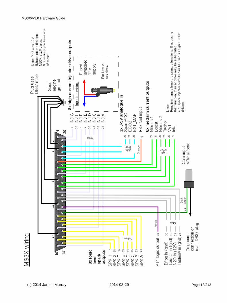
MS3X plug (DIYAutoTune.com colors)
Pin# Name Color/Stripe In/Out Function Max amps
1 Inj G White/Dark Blue Out Injector G output 5A
2 GND Black GND POWER GROUND -
3 GND Black GND POWER GROUND -
4 Inj F White/Dark Green Out Injector F output 5A
5 Flex Orange In Flex fuel -
6 Boost Light Green/Red Out Mid-current output 3A
7 Inj E White/Red Out Injector E output 5A
8 GND Black GND POWER GROUND -
9 Idle Light Green/Pink Out Mid-current output 3A
10 Inj D White/Pink Out Injector D output 5A
11 Launch in Gray/Red In Ground-switch input -
12 GND Black GND POWER GROUND -
13 Inj C White/Light Green Out Injector C output 5A
14 Spark A Yellow Out 0-5V logic spark A output 0.03A
15 Spark C Yellow/Light Green Out 0-5V logic spark C output 0.03A
16 Inj B White/Orange Out Injector B output 5A
17 GND Black GND POWER GROUND -
18 Spark G Yellow/Dark Blue Out 0-5V logic spark output 0.03A
19 Inj A White Out Injector A output 5A
20 Inj H White/Purple Out Injector H output 5A
21 SpareADC Light Blue In 0-5V analog input -
22 EGO2 Light Blue/Dark Blue In 0-5V analog input -
23 EXT_MAP Light Blue/Red In 0-5V analog input -
24 Nitrous 1 Light Green Out Mid-current output 3A
25 Nitrous 2 Light Green/Dark Blue Out Mid-current output 3A
26 Tacho Light Green/Orange Out Mid-current output 3A
27 VVT Light Green/Dark Green Out Mid-current output 3A
28 Tableswitch in Gray/Purple In Ground-switch input -
29 Nitrous in Gray/Dark Blue In +12V switch input -
30 Datalog in Gray In Ground-switch input -
31 PT4 Purple In/Out 0/5V input or output 0.02A
32 Cam input Dark Green In 'Cam' Tach input -
33 Spark B Yellow/Orange Out 0-5V logic spark B output 0.03A
34 Spark D Yellow/Pink Out 0-5V logic spark D output 0.03A
35 Spark E Yellow/Red Out 0-5V logic spark E output 0.03A
36 Spark F Yellow/Dark Green Out 0-5V logic spark F output 0.03A
37 Spark H Yellow/Purple Out 0-5V logic spark H output 0.03A
(c) 2014 James Murray 2014-08-29 Page 19/212

MS3X/V3.0 Hardware Guide
3.4 Inputs
3.4.1 Crank and Cam Tach inputs
These sensors provide the Megasquirt with engine position information and are used to schedule fuel and spark.See chapter 5 for more information.
3.4.2 MAP (Manifold Absolute Pressure) sensorThe MS3/V3.0 uses an internal MAP sensor.
This sensor measures air pressure on absolute scale where zero is a complete vacuum and sea-level ambient pressure is around 101kPa. This sensor is the primary input for the "Speed-Density" fuel algorithm. Alpha-N users do not require a MAP sensor and can optionally use the built-in sensor as a baro sensor.
The pressure barb is connected to a full-vacuum source at the intake manifold. When tapping into any existing vacuum ports on a throttle body be sure to select one that gives full vacuum when the throttle is closed. (i.e. not a "ported vacuum" source that would connect to a distributor.)
(c) 2014 James Murray 2014-08-29 Page 20/212
MAP sensor hose connects here

MS3X/V3.0 Hardware Guide
0 50 100 150 200 250 3000
1
2
3
4
5
MAP sensor response
Absolute pressure kPa
Vo
ltag
e
Optionally a second sensor may be installed to measure barometric pressure. This works in the same way but typically a 1-bar sensor is used. The pressure feed port is left open to the atmosphere and will help the engine respond to changes in ambient pressure or elevation.
3.4.3 IAT/MAT (Intake/Manifold Air Temperature) sensor
This external sensor measures the temperature of the air entering the engine. This is used to calculate air density and is a key factor in the Speed-Density fuel calculation.
The temperature sensor is a variable resistor (a thermistor). Higher temperatures give a lower resistance, the response is non-linear.
Any install not using a MAT should connect the MAT input to sensor ground to prevent the reading "floating".
A good sensor will have two wires, one wire connects to sensor ground, the other to the MAT input on the ECU.
One-wire sensors are not recommended.
The sensor may either be an "open-element" or "closed-element" type sensor. "Open-element" sensor have a thermistor directly exposed to the air-stream - this type of sensor is required for turbo-charged application wherethe air temperature can change quickly. The "closed-element" type sensor is identical to a coolant temperature sensor and has an encapsulated thermistor - these respond too slowly for turbo-charged application.
(c) 2014 James Murray 2014-08-29 Page 21/212
MS3X/V3.0 Hardware Guide
-40 10 60 110 160 210 260 3100
20000
40000
60000
80000
100000
120000
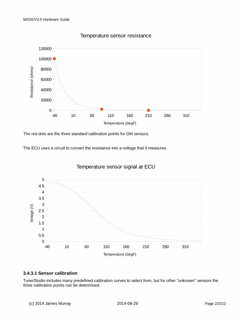
Temperature sensor resistance
Temperature (degF)
Re
sist
an
ce (
oh
ms)
The red dots are the three standard calibration points for GM sensors.
The ECU uses a circuit to convert the resistance into a voltage that it measures.
-40 10 60 110 160 210 260 3100
0.5
1
1.5
2
2.5
3
3.5
4
4.5
5
Temperature sensor signal at ECU
Temperature (degF)
Vo
ltag
e (
V)
3.4.3.1 Sensor calibration
TunerStudio includes many predefined calibration curves to select from, but for other "unknown" sensors the three calibration points can be determined.
(c) 2014 James Murray 2014-08-29 Page 22/212

MS3X/V3.0 Hardware Guide
The manual calibration process requires the use of a multimeter set to measure resistance and ideally a thermometer. Without a thermometer your calibration will be fairly close but not perfect.
1. Set the meter to ohms and connect the meter to the two terminals on the MAT or CLT sensor.
2. Allow the sensor to reach room temperature.
3. Take the resistance reading.
4. Measure room temperature using a thermometer (typically 20°C / 68°F)
5. Place the end of the sensor in a mixture of ice melting in water and allow it to stabilize.
6. Take the resistance reading.
7. Measure the ice/water temperature using a thermometer (typically 0°C / 32°F)
8. Place the end of the sensor in a pan of boiling water and allow it to stabilize.
9. Take the resistance reading.
10. Measure the boiling water temperature using a thermometer (typically 100°C / 212°F)
You now have the three calibration points for TunerStudio.
For a GM sensors these should be close to:Where °C °F Ohms
Ice/water 0 32 9441
Room temp. 20 68 3518
Boiling water 100 212 172
Note that the default calibration data in TunerStudio goes down to -40° but that's rather difficult to measure in the normal workshop.
(c) 2014 James Murray 2014-08-29 Page 23/212

MS3X/V3.0 Hardware Guide
3.4.4 CLT (Coolant Temperature) sensor
This external sensor measures the temperature of the engine coolant (or cylinder head for air-cooled engines.) Itis primarily used to provide additional fuel during engine warm-up.
The coolant temperature is a thermistor and works in the same way as the air temperature sensor.
Any install not using a CLT should connect the CLT input to sensor ground to prevent the reading "floating".
A good sensor will have two wires, one wire connects to sensor ground, the other to the CLT input on the ECU.
One-wire sensors are not recommended.
3.4.5 TPS (Throttle Position Sensor)
This external sensor measures the position of the throttle plate. It is a variable resistor (potentiometer) and sends a 0-5V signal back to the Megasquirt. The sensor has three wires, 5V supply (TPSVREF), Ground (sensor ground return) and signal. The Megasquirt converts the signal to a 0-100% scale using your calibration numbers. 0% corresponds to fully closed, 100% to fully open.
Switch-type throttle position sensors are not recommended.
(c) 2014 James Murray 2014-08-29 Page 24/212
MS3X/V3.0 Hardware Guide
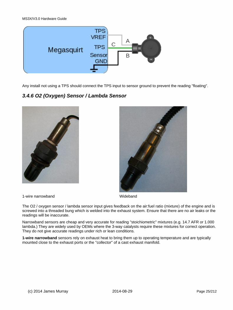
Any install not using a TPS should connect the TPS input to sensor ground to prevent the reading "floating".
3.4.6 O2 (Oxygen) Sensor / Lambda Sensor
1-wire narrowband Wideband The O2 / oxygen sensor / lambda sensor input gives feedback on the air:fuel ratio (mixture) of the engine and is screwed into a threaded bung which is welded into the exhaust system. Ensure that there are no air leaks or thereadings will be inaccurate.
Narrowband sensors are cheap and very accurate for reading "stoichiometric" mixtures (e.g. 14.7 AFR or 1.000 lambda.) They are widely used by OEMs where the 3-way catalysts require these mixtures for correct operation.They do not give accurate readings under rich or lean conditions.
1-wire narrowband sensors rely on exhaust heat to bring them up to operating temperature and are typically mounted close to the exhaust ports or the "collector" of a cast exhaust manifold.
(c) 2014 James Murray 2014-08-29 Page 25/212

MS3X/V3.0 Hardware Guide
4-wire narrowband sensors include a heater and a signal ground. These can be mounted further away from theexhaust port as they are self heating. Preferable to a 1-wire.
Typical wiring
Blacks = heater power and ground
Blue = signal ground
White = O2 signal
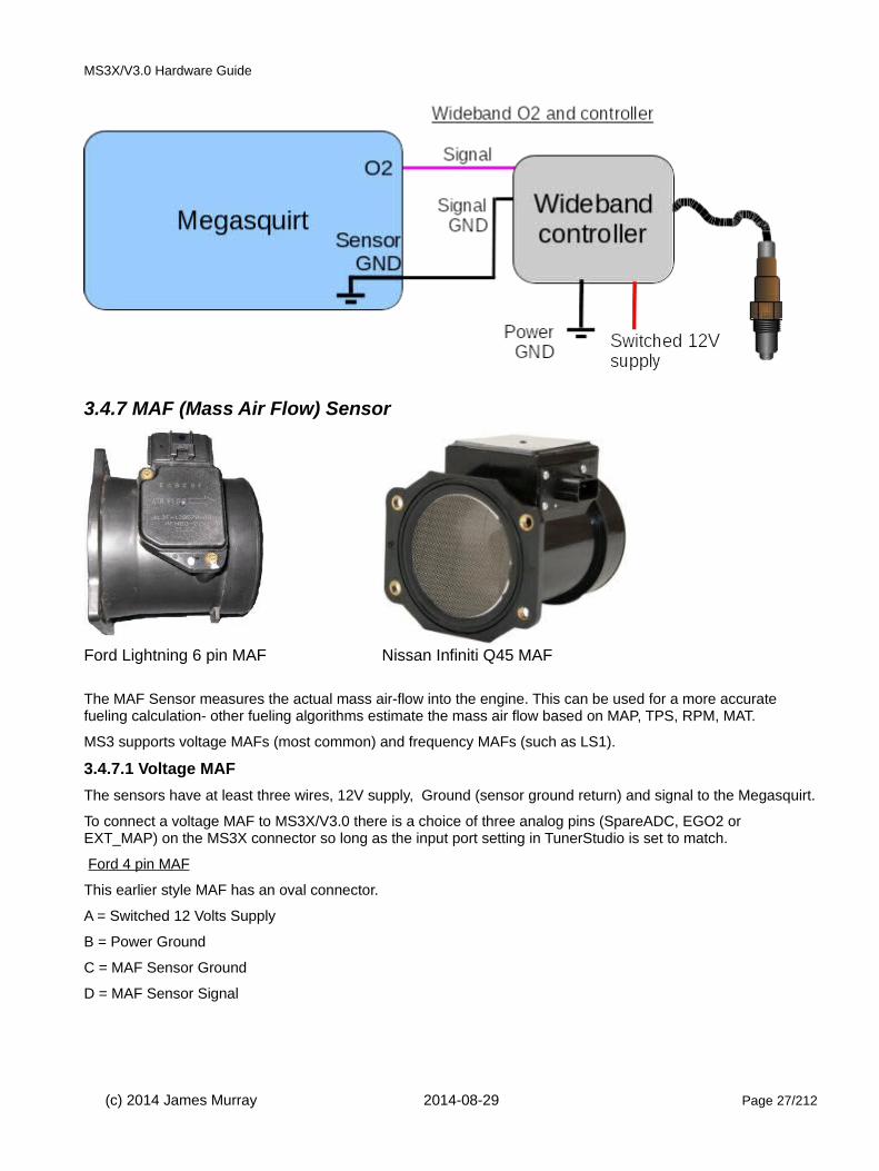
Wideband sensors require an external controller for use with the Megasquirt. Widebands are more expensive than narrowband sensors but give readings over a far wider range of exhaust mixtures. When used with a Megasquirt they give you the ability to tune your engine in the rich (power) and lean (cruise) regions. Strongly recommended.
The better controllers offer a signal ground which should be connected to the Megasquirt sensor ground. Other models require grounding to the engine block only. Consult the directions that came with your wideband controller.
(c) 2014 James Murray 2014-08-29 Page 26/212
MS3X/V3.0 Hardware Guide
3.4.7 MAF (Mass Air Flow) Sensor
Ford Lightning 6 pin MAF Nissan Infiniti Q45 MAF
The MAF Sensor measures the actual mass air-flow into the engine. This can be used for a more accurate fueling calculation- other fueling algorithms estimate the mass air flow based on MAP, TPS, RPM, MAT.
MS3 supports voltage MAFs (most common) and frequency MAFs (such as LS1).
3.4.7.1 Voltage MAF
The sensors have at least three wires, 12V supply, Ground (sensor ground return) and signal to the Megasquirt.
To connect a voltage MAF to MS3X/V3.0 there is a choice of three analog pins (SpareADC, EGO2 or EXT_MAP) on the MS3X connector so long as the input port setting in TunerStudio is set to match.
Ford 4 pin MAF
This earlier style MAF has an oval connector.
A = Switched 12 Volts Supply
B = Power Ground
C = MAF Sensor Ground
D = MAF Sensor Signal
(c) 2014 James Murray 2014-08-29 Page 27/212

MS3X/V3.0 Hardware Guide
Ford 6 pin MAF
This MAF also includes an intake air temperature sensor, so an additional MAT is not required.
E = IAT Sensor Ground
A = Switched 12 volts supply
B = Power Ground
C = MAF Sensor Ground
D = MAF Sensor Signal
F = IAT Sensor Signal
Nissan Infiniti Q45 90mm MAF
B = MAF Sensor Signal (White)
(c) 2014 James Murray 2014-08-29 Page 28/212

MS3X/V3.0 Hardware Guide
D = Ground (Black)
E = Switched 12 volts supply (Black/white)
3.4.7.2 Frequency MAF
Many GM (USA) vehicles from 1994 onwards use an AC Delco frequency MAF. (Earlier Bosch units are voltage type.)
The frequency signal has the potential advantage of not being susceptible to any ground differences. Due to the way that the frequency is measured, the reading becomes more coarse at higher frequencies. At 10kHz the measurement has 1% accuracy, 15kHz is 1.5%. For better repeatability, it is suggested to get a largerMAF and recalibrate in preference to running above 10kHz.
The sensors have at least three wires, 12V supply, Ground (sensor ground return) and signal to the Megasquirt.
To connect a frequency MAF to MS3X/V3.0, typically PT4 on the MS3X connector should be used. Set the input port setting in TunerStudio to match.
Pin 'JS10 PT5' is also usable but requires hardware modifications inside the Megasquirt case. (See the MS3/V3.0 Hardware manual)
Be sure to set the minimum and maximum frequencies before altering the flow curve. Pre-defined calibration curves are available for GM LT1, LS1, LSx MAFs. When using the 650g/s file (~800hp) set the min/max frequencies to 1000Hz and 11500Hz When using the 1300g/s file (~1600hp) set the min/max frequencies to 1000Hz and 14125Hz For larger flowing MAFs a custom calibration will be required.
(c) 2014 James Murray 2014-08-29 Page 29/212

MS3X/V3.0 Hardware Guide
GM 3 wire MAF (1994-2000)
A = MAF Sensor Signal (Yellow)
B = Power Ground (Black/white)
C = Switched 12 volts supply (Pink)
GM MAF sensors require a 1k pullup resistor to be installed between the signal output and 5V.
GM LS1 5 wire MAF (2001-2006)
This MAF also includes an intake air temperature sensor, so an additional MAT is not required.
Pinout is provided for reference only – double check your application. LS3/LS7 believed to be different.
A = IAT Sensor Ground
B = IAT Output Signal
C = Power Ground
D = Switched 12 volts supply
E = MAF Sensor Signal
(c) 2014 James Murray 2014-08-29 Page 30/212

MS3X/V3.0 Hardware Guide
3.4.7.3 MAF flow curve
The flow response of MAF sensors is non-linear and uses a calibration tuning curve in the Megasquirt to convertthe input signal into a grammes/second flow rate number.
0 0.5 1 1.5 2 2.5 3 3.5 4 4.5 50
50
100
150
200
250
300
MAF sensor response (Ford V8)
Voltage (V)
Ma
ss a
ir fl
ow
(g
/se
c)
(c) 2014 James Murray 2014-08-29 Page 31/212

MS3X/V3.0 Hardware Guide
3.4.8 Flex / Switch input
The Flex fuel (or fuel composition) sensor detects the percentage of ethanol within the fuel passing through it. This can be used by the Megasquirt to automatically adjust fuel and spark to allow for the change in fuel. Higher ethanol blends require more pulsewidth and additional spark advance.
The GM sensor (shown) uses barbed pipes, the Ford sensor uses screw in fittings.
Looking into sensor connector from left.
Ground (GM = white, Ford = Black)
+12 Volt supply (GM/Ford = pink)
Output signal, (GM = purple, Ford = white)
GM and Ford appear to use the same sensor but the letters on the connector may be different.
To connect a Flex Fuel sensor to MS3X/V3.0, typically the 'FLEX' pin will be used so long as the input port setting in TunerStudio is set to match.
(c) 2014 James Murray 2014-08-29 Page 32/212
MS3X/V3.0 Hardware Guide
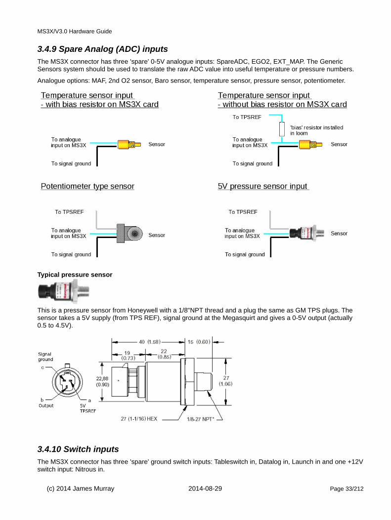
3.4.9 Spare Analog (ADC) inputsThe MS3X connector has three 'spare' 0-5V analogue inputs: SpareADC, EGO2, EXT_MAP. The Generic Sensors system should be used to translate the raw ADC value into useful temperature or pressure numbers.
Analogue options: MAF, 2nd O2 sensor, Baro sensor, temperature sensor, pressure sensor, potentiometer.
Typical pressure sensor
This is a pressure sensor from Honeywell with a 1/8"NPT thread and a plug the same as GM TPS plugs. The sensor takes a 5V supply (from TPS REF), signal ground at the Megasquirt and gives a 0-5V output (actually 0.5 to 4.5V).
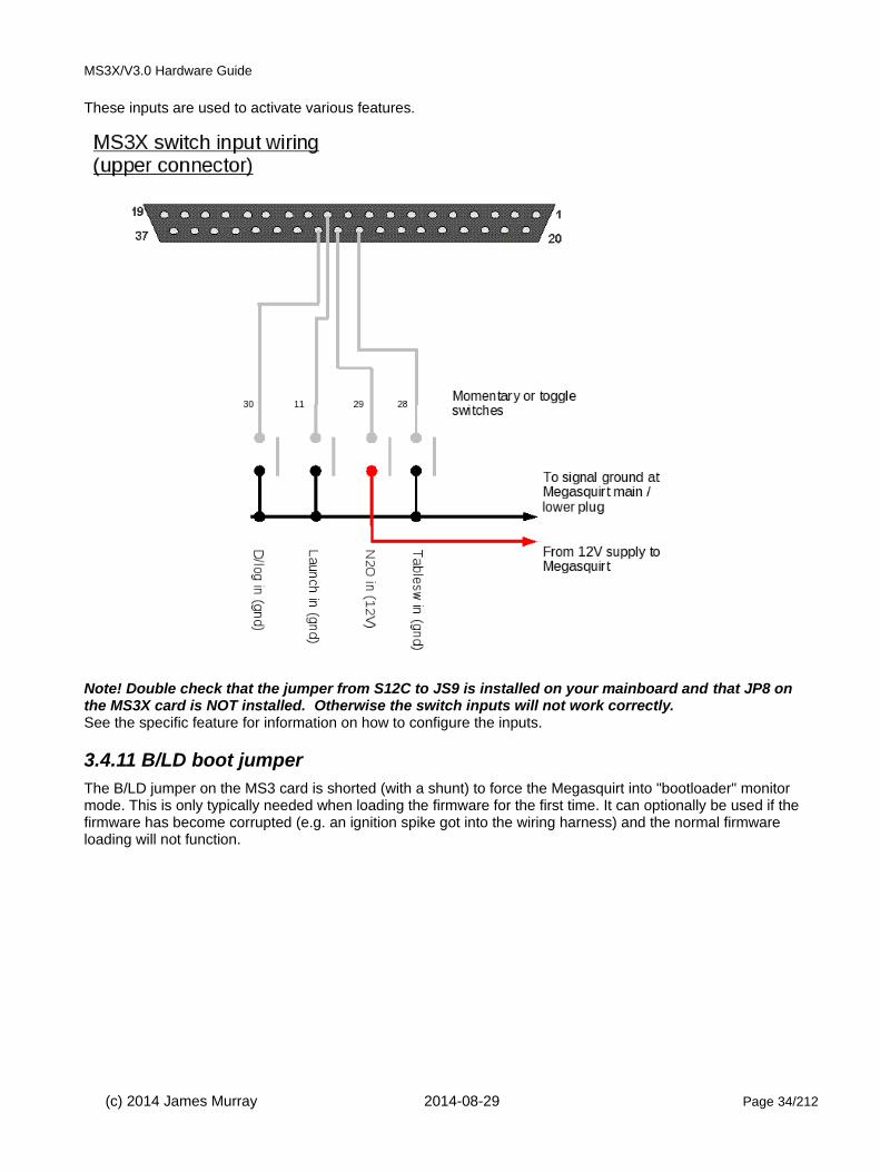
3.4.10 Switch inputsThe MS3X connector has three 'spare' ground switch inputs: Tableswitch in, Datalog in, Launch in and one +12Vswitch input: Nitrous in.
(c) 2014 James Murray 2014-08-29 Page 33/212
MS3X/V3.0 Hardware Guide
These inputs are used to activate various features.
Note! Double check that the jumper from S12C to JS9 is installed on your mainboard and that JP8 on the MS3X card is NOT installed. Otherwise the switch inputs will not work correctly.See the specific feature for information on how to configure the inputs.
3.4.11 B/LD boot jumperThe B/LD jumper on the MS3 card is shorted (with a shunt) to force the Megasquirt into "bootloader" monitor mode. This is only typically needed when loading the firmware for the first time. It can optionally be used if the firmware has become corrupted (e.g. an ignition spike got into the wiring harness) and the normal firmware loading will not function.
(c) 2014 James Murray 2014-08-29 Page 34/212

MS3X/V3.0 Hardware Guide
3.4.12 CAN comms The CANH/L wires are used to connect to add-on units such as transmission control, CANEGT interfaces, data capture or compatible dashboards.
The Megasquirt includes a terminating resistor.
To use the CAN connections, you need to run internal jumper wires:
JS6 -> SPR1 = CANH
JS8 -> SPR2 = CANL
3.4.13 Knock sensorMegasquirt supports knock sensing with an internal or external interface to the knock sensor.
You can only connect a sensor directly to the Megasquirt when the internal knock module is installed.
Three configurations are available - on/off, analogue or internal
The on/off mode can be used with a GM ESC module (16022621, 16052401)
(c) 2014 James Murray 2014-08-29 Page 35/212

MS3X/V3.0 Hardware Guide
The connection to the Megasquirt is on JS4 or JS5.
In the analogue mode, 0-5V signal is fed into JS4 or JS5 using a protective circuits as in 3.4.9.1.
In the internal mode, an add-on card is required. This gives superior knock-sensing control with software control. It allows per-cylinder detection and tuning to specific engine bores size.
(c) 2014 James Murray 2014-08-29 Page 36/212

MS3X/V3.0 Hardware Guide
3.4.13.1 Internal Knock Module
The knock module uses a purpose designed knock-sensing amplifier chip to filter knock signals from a standard OEM style knock sensor and interface with the Megasquirt-3. The module uses the signals for the LEDs and JS11. So you need to use the MS3X outputs to control ignition. i.e. "LED spark" will not work.
The module requires soldering to the top of the MS3 card.
• First ensure you are confident in this task, if not entrust to someone else or consult your dealer. • Remove the upper case and MS3X card for access. • Position the knock module as shown in line with rear or the DIP40 pins (i.e. adjacent to C3 on the MS3
card) • Solder on the six connecting pins visible and the two support pins on the other side.
Use a magnifying glass if required to ensure you have created a good connection.
• Remove the MS3 card from the board.
• Solder a flying wire from the PM2 pad on the knock module to the PM2 pin header on the reverse of the MS3 card.
(c) 2014 James Murray 2014-08-29 Page 37/212

MS3X/V3.0 Hardware Guide
• Re-install MS3 card.
• Pads K1 and K2 are inputs for knock channels 1 and 2. They should be connected to a spare connector pin of your choice (e.g. SPR3,4)
A typical knock sensor:
Effectively, it consists of a microphone and listens to the engine. Connect one wire to ground at the Megasquirt and the other wire to the knock input. (K1 or K2)
See the TunerStudio Reference for settings.
3.4.14 Realtime clockThe real time clock module allows the Megasquirt-3 to maintain time and date when the power is removed. The main benefit from this is to allow the timestamp to be recorded with SDcard datalogs to enable easier future identification.
The module requires soldering to the top of the MS3X card.
• First ensure you are confident in this task, if not entrust to someone else or consult your dealer. • Remove the upper case and MS3X card. • Position the RTCC module as shown i.e. GND aligns with GND : 5V aligns with VCC : the empty pad H2
is above H2. • Solder on the four connecting pins from below the MS3X card keeping the RTCC module level.
Use a magnifying glass if required to ensure you have created a good connection.
(c) 2014 James Murray 2014-08-29 Page 38/212
MS3X/V3.0 Hardware Guide
• Carefully install the CR1220 Lithium battery, noting polarity. The larger (+) side is upwards, matching the(+) on the retainer. Be aware that once the battery is installed, the circuit is live and you must prevent short circuits.
• If your install is subjected to vibration it is strongly recommended that some glue is used to retain the battery and a support is made beneath the exposed end of the module.
• In TunerStudio go to CANbus/testmodes->Real Time Clock, set the input type to "On-board"
• Power cycle as instructed. • You can set the clock by pressing the button. The new time will show next time you enter the menu.
3.4.15 PT4 input / outputPT4 can be used as a low current 0-5V logic output or a 0-5V logic input.
3.4.16 Speed sensor inputsThe speed sensors system expects to receive a 0-5V pulsed signal internally at the processor.
The switch inputs 'Datalog in', 'Tableswitch in', 'Launch in' can be used for low frequency signals from a hall/gear-tooth sensor e.g. picking up from the rear or wheel studs.
High tooth count sensors such as ABS rings will create too high a frequency for these inputs. The PT4 input can accomodate a high frequency 0-5V input signal.
With some DIY, the spare inputs internally on the mainboard can be used for higher frequencies with a suitable interface circuit - replicate the PT4 input circuit shown in the schematics.
VR sensors will need a suitable interface circuit to convert the AC signal into a 0-5V pulsed signal.
3.5 Outputs
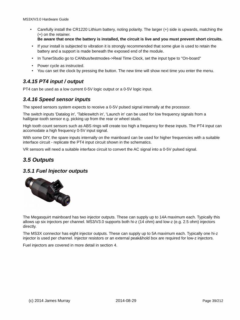
3.5.1 Fuel Injector outputs
The Megasquirt mainboard has two injector outputs. These can supply up to 14A maximum each. Typically this allows up six injectors per channel. MS3/V3.0 supports both hi-z (14 ohm) and low-z (e.g. 2.5 ohm) injectors directly.
The MS3X connector has eight injector outputs. These can supply up to 5A maximum each. Typically one hi-z injector is used per channel. Injector resistors or an external peak&hold box are required for low-z injectors.
Fuel injectors are covered in more detail in section 4.
(c) 2014 James Murray 2014-08-29 Page 39/212

MS3X/V3.0 Hardware Guide
3.5.2 Ignition outputs
The MS3X connector has eight 0-5V logic ignition outputs.
Ignition outputs and the ignition system are covered in more detail in section 5.
3.5.3 Fuel pump outputThe Fuel Pump output is low current low-side output used to drive a relay that switches the high current fuel pump. The coils and injectors should also take power from this relay so that when the engine is shutdown or stalls these are positively disconnected from power.
3.5.4 Idle valveAn idle valve is used to allow additional air into the engine, bypassing the throttle plate. This works similarly to the part of the choke mechanism on a carburettor and raises idle speed during warmup. Additionally it can be used for "closed-loop idle" to maintain a steady idle RPM under varying engine loads (lights on vs. off etc.)
As standard, the MS3/V3.0 supports on/off type valves and stepper idle motors. Servo type idle valves are not currently supported.
3.5.4.1 On/Off Idle Valve
The standard V3.0 circuit is used to operate a relay to drive the idle valve.
(c) 2014 James Murray 2014-08-29 Page 40/212
Megasquirt
12V85
86
FP output
87
30
Standard 4 pin automotive relay

MS3X/V3.0 Hardware Guide
3.5.4.2 2-wire PWM idle valve (mainboard)
2-wire PWM idle valves are used by Ford, VW, Volvo and many others. The MS3/V3.0 mainboard requires an internal modification to be able to drive this type of valve.
MS3X customers do not need to do this! See section 3.5.4.4
Parts required:
TIP122
mica insulation kit
1N4001
a) Remove Q4, Q20, D8 if fitted.
b) Cut the legs of the TIP122 so they are half the length they were as new.
c) Fit a piece of mica insulation under it and using plastic screws bolt it to the heatsink in a spare position, or boltonto the case.
d) Solder a wire from the center pin of Q4 to the pin 1 of the TIP122.
e) Solder a wire from the right of R39 to the pin 3 of the TIP122
(Some installs might connect pin 3 to the bottom of R43, that's fine too.)
f) Ensure D8 is not fitted or remove it if it is.
g) Get an IN4001 and install the non banded end into the right hole of D8 and the banded end to S12.
h) Solder a wire from the non-banded side of the 1N4001 diode to pin 2 of the TIP122.
(c) 2014 James Murray 2014-08-29 Page 41/212
Megasquirt
12V85
86
FIDLE output
87
30
Standard 4 pin automotive relay
V3.0 standard

MS3X/V3.0 Hardware Guide
The 12V supply for the idle valve must be a fused switched supply - ideally from the fuel pump relay. It must never be supplied power when the Megasquirt is off.
(c) 2014 James Murray 2014-08-29 Page 42/212
Megasquirt
12V
FIDLE output
Solenoid type PWM idle valve
V3.0 modified

MS3X/V3.0 Hardware Guide
3.5.4.3 4-wire or 6-wire stepper idle valve
4-wire stepper idle valves are common on many GM vehicles. MS3 can control these directly.
All that is required is that internal jumper wires are installed
a) JS0 to IAC1A
b) JS1 to IAC1B
c) JS2 to IAC2A
d) JS3 to IAC2B
e) JS9(+12V) to S12C
The 4-wire stepper motors commonly used by GM are "bi-polar" type.
(c) 2014 James Murray 2014-08-29 Page 43/212

MS3X/V3.0 Hardware Guide
Other manufacturers use 5- or 6-wire steppers which are uni-polar.
These are usually wired as shown in the schematic below, with a center tap on each of two windings. In use, thecenter taps of the windings are typically wired to the 12V supply, and the two ends of each winding are alternately grounded to reverse the direction of the field provided by that winding.
3.5.4.4 2-wire PWM idle valve (MS3X)
The MS3X connector allows direct connection of 2-wire idle valves without extensive internal modifications.
(c) 2014 James Murray 2014-08-29 Page 44/212
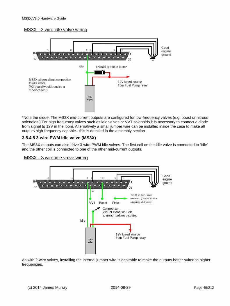
MS3X/V3.0 Hardware Guide
*Note the diode. The MS3X mid-current outputs are configured for low-frequency valves (e.g. boost or nitrous solenoids.) For high frequency valves such as idle valves or VVT solenoids it is necessary to connect a diode from signal to 12V in the loom. Alternatively a small jumper wire can be installed inside the case to make all outputs high-frequency capable - this is detailed in the assembly section.
3.5.4.5 3-wire PWM idle valve (MS3X)
The MS3X outputs can also drive 3-wire PWM idle valves. The first coil on the idle valve is connected to 'Idle' and the other coil is connected to one of the other mid-current outputs.
As with 2-wire valves, installing the internal jumper wire is desirable to make the outputs better suited to higher frequencies.
(c) 2014 James Murray 2014-08-29 Page 45/212

MS3X/V3.0 Hardware Guide
3.5.5 Tacho outputA tacho output typically provides a 0-12V pulsed signal that is suitable for driving an aftermarket tachometer (revcounter.)
Some older tachometers expect the high-current "spike" from the ignition coil and may not work directly with a 0-12V signal.
As standard, the MS3X connector 'Tacho' output will provide a 0-12V signal that is suitable for most aftermarket tachometers. (Ensure that JP2 is in place on the MS3X card.)
Alternatively, if not using a stepper idle valve, outputs IAC1A, IAC1B, IAC2A, IAC2B provide a 0-12V signal which could be used directly for a tacho output. Ensure that the jumpers in section 3.5.4.5 are connected.
High-voltage tachometers may require the addition of a relay coil to generate the voltage "spike" they require. It is suggested that the mechanism inside the relay is removed or it will buzz loudly!
Circuit for high voltage tacho.
3.5.6 Mid current PWM / relay outputThe MS3X connector has six mid-current outputs that can be used for boost solenoids, relays or small lamps. The 12V feed for the relays, solenoids etc. must turn off when the Megasquirt is turned off, so take it from the Main Relay or Fuel Pump Relay - otherwise you may backfeed the Megasquirt.
(c) 2014 James Murray 2014-08-29 Page 46/212
MS3X Tacho output
12V
Relaycoil
Tacho
Megasquirt
12V
Solenoid valve
Mid current output

MS3X/V3.0 Hardware Guide
All outputs are low-side ground-switching.
(c) 2014 James Murray 2014-08-29 Page 47/212
Megasquirt
12V
Solenoid valve
Mid current output

MS3X/V3.0 Hardware Guide
3.6 Bench test wiringBefore installing on your engine, it can be useful to install the Megasquirt on the bench to become familiar with the tuning software.
3.6.1 Minimal connectionThe bare minimum for testing is a fused 12V supply, ground and the serial connection to your tuning computer.
3.6.2 JimStim connectionFor more extensive testing, the JimStim can be used. This has the mating DB37 connector to plug directly into your Megasquirt and can simulate many of the engine sensors. Make sure that the JimStim does not touch anything conductive as it is uninsulated.
(c) 2014 James Murray 2014-08-29 Page 48/212
1928
GN
D
12V
DC
1A fuse

MS3X/V3.0 Hardware Guide
3.6.3 V10 and V12 support (DIY mods)The MS3 firmware supports V10 and V12 engines in full sequential fuel and coil-on-plug. However, the stock hardware only has provision for eight channels so DIY is required to add the addition channels - or purchase pre-configured from your vendor. (Consider MS3-Pro for a non-DIY alternative.)
For V10 you need to add spkI,J, injI,J. For V12 you need to add spkI,J,K,L and injI,J,K,L. As always the coils and injectors are wired up in firing-order.
On the software side, in your Project Properties->Settings in TunerStudio, enable CYL_10_16_SUPPORT.
Injection For injection, a suitable PCB is available from JB Perf. The ignition FETs and resistors are not required.
The recommended connection points for injI,J,K,L are the 'spare' pins on the MS3X card.
(c) 2014 James Murray 2014-08-29 Page 49/212

MS3X/V3.0 Hardware Guide
Users of the Realtime clock add-on cannot use H3 and H4 as they are already taken, there is a software option to use the mainboard injector channels instead. However, you must still use identical injector drivers for each injector.
When using the JBperf board, connect: Function MS3X JBperf board
Inj I H3 inj 1
Inj J H4 inj 2
Inj K H1 inj 3
Inj L H2 inj 4Ignition The recommended method to add the extra ignition channels is to replicate the circuits used on the MS3X card by installing components in the prototype area of the mainboard (or on your own additional PCB.)
(c) 2014 James Murray 2014-08-29 Page 50/212

MS3X/V3.0 Hardware Guide
Having built that circuit, either connect to your own connector, or route through the JBperf board mentioned above. The ignition FETs are not needed and should not be installed. Jumper from the output of the buffer circuityou built to the middle pin of each FET. i.e. spkI -> ign1, spkJ -> ign2 etc.
The output connection from the JBperf is
Injector I/J outputs setting should be set to match your wiring.Spark hardware on the ignition settings page should be set to "MS3X"
(c) 2014 James Murray 2014-08-29 Page 51/212
MS3X/V3.0 Hardware Guide
4: Fuel SystemFuel is extremely flammable and fuel systems run at high pressures. Be sure to have a fire extinguisher to hand in case of mishap and take appropriate caution when working on fuel systems.
4.1 IntroductionThe fuel system install comprises electrical and plumbing work.
The Megasquirt mainboard has two injector outputs. These can supply up to 14A maximum each. Typically this allows up six injectors per channel. MS3/V3.0 supports both hi-z (14 ohm) and low-z (e.g. 2.5 ohm) injectors directly.
The MS3X connector has eight injector outputs. These can supply up to 5A maximum each. Typically one hi-z injector is used per channel. Injector resistors or an external peak&hold box are required for low-z injectors.
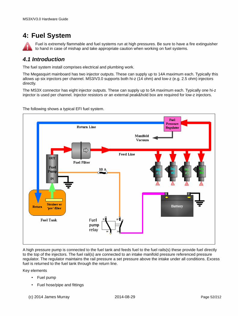
The following shows a typical EFI fuel system.
A high pressure pump is connected to the fuel tank and feeds fuel to the fuel rails(s) these provide fuel directly to the top of the injectors. The fuel rail(s) are connected to an intake manifold pressure referenced pressure regulator. The regulator maintains the rail pressure a set pressure above the intake under all conditions. Excess fuel is returned to the fuel tank through the return line.
Key elements
• Fuel pump
• Fuel hose/pipe and fittings
(c) 2014 James Murray 2014-08-29 Page 52/212

MS3X/V3.0 Hardware Guide
• Injectors
• Injector mounting
• Fuel rails
• Pressure regulator
4.1.1 Existing EFI VehicleMost vehicles with EFI already fitted are readily adaptable to use Megasquirt for control. Typically all of the fuel system components will be readily suitable.
However, if like many users you are increasing the power of your engine, you will need to consider whether yourinjectors are large enough and whether your fuel pump has adequate flow. In particular note that all fuel pumps flow less fuel as the pressure increases - so if you are boosting your engine you will be needing more fuel underthe conditions when your pump can supply less!
Some recent engines use ECU controlled fuel pumps or dead-head systems with no regulator. At this time, these are not easily controlled and you are advised to convert to a conventional system with a vacuum referenced bypass regulator and return line.
4.1.2 Retro-fit EFI VehicleWhen installing EFI on a previously carburetted vehicle or a new build you have to source all the required fuel system components. There are many choices open to the retro-fit market. Be aware that a high horsepower install will often spend more on the fuel system than the ECU.
4.2 Single Fuel pumpYou will need a high pressure pump with enough volume at your operating pressure to feed you engine under maximum load. Typical pressures needed in the neighborhood of ~45 psi for port fuel injection, ~10-20 psi for TBI injection. A port injection pump will work with TBI, but not vice-versa.
A standard EFI install uses a single high pressure pump connected as per the diagram in 4.1 above. Depending on your target power output, many OEM style pumps may be suitable. Surprisingly, some of the Bosch inline EFI pumps installed on 100hp cars are actually rated to 450hp fuel capacity. OEM style pumps are a usually a good choice as they are designed for trouble free operation for tens of thousands of miles.
OEMs sometimes place the pump inside the fuel tank. In an EFI retrofit it is generally easier to use an external fuel pump.
If an OEM style pump does not offer sufficient output, there are plenty of aftermarket high volume EFI pumps onthe market.
4.3 Low pressure / high pressure - twin pumpFor a basic retrofit, you may find that a low pressure/high pressure system is a simpler way to avoid tank modifications for the fuel pickup, although a fuel return to the tank is still required.
(c) 2014 James Murray 2014-08-29 Page 53/212

MS3X/V3.0 Hardware Guide
The low pressure side can be your existing electric fuel pump. You need to add the surge/swirl tank and high pressure side. For the tank return you may already have an return or evap canister connection or could connect into the filler neck, ensuring that fuel returns to the tank and cannot leak out of the vehicle.Surge/swirl tank can be purchased or you can make your own. Use thick wall TIGed aluminium or brazed steel. Ensure it is totally leak free.
4.4 Wiring the Fuel PumpTo activate the fuel pump, the Megasquirt provides a ground for the fuel pump relay circuit -see the main wiring diagram.Ordinarily, at power on, the Megasquirt will run the fuel pump for 2 seconds, then when you start cranking the fuel pump is enabled again. If you stop cranking before the engine starts or you stall, the pump is turned off.
An inertial safety shut off switch is a good safety feature – it is used to kill power to the pump if there is significant impact to vehicle.
4.5 Fuel LineSteel tubing or Cunifer (Bundy tubing) is recommended, but you MUST have short sections of flexible line in the feed and return lines between the engine and frame to allow for engine movement. The return line should have minimal restriction. For reference, GM systems typically have 3/8" feed lines and 5/16" return lines.
You may be able to use your original fuel line as a return line, plumbing a new 3/8" (10mm) line for fuel supply. You can run the return line into the tank, or reroute it to a fitting or nipple you install in the fuel tank filler neck/tube assembly (in which case you may be able to use the original pick-up for your supply line). If you run a new pick-up into the tank, it will need a filter.
You may have to fabricate fuel lines for your system. Tubing is available in steel, cunifer (bundy), stainless steel,
(c) 2014 James Murray 2014-08-29 Page 54/212

MS3X/V3.0 Hardware Guide
and aluminum for this purpose. Do not use plain copper and it can fatigue fail with dangerous leaks resulting. The size is generally given as the outside diameter of the tubing. Unless you have a very unusual combination (or very high horsepower, well over 500+), you should be able to use 3/8" tubing for both the supply and return lines.
Buy a good tubing bender (there are numerous styles in various price ranges) so that you don't kink or collapse the tubing while bending it.
Most fittings and adapters in the USA automotive aftermarket are based on a 37° sealing angle (SAE J514 37° -formerly known as JIC). These are also often referred to simply as AN fittings. Male and female 37° fittings will mate together for a leak-proof connection. Be aware that 45° fittings (commonly available in the USA) are not interchangeable with 37° fittings.
Abrasion (the rubbing of the hose against some other component) is the number one cause of hose failure. A leaking fuel hose can start a very dangerous fire in your car, so make sure hose assemblies are routed properly to reduce the chance of any abrasion damage. Use a support every 12 to 18 inches (30 to 45 cm) to secure the hose. For chafe protection, be sure to install a grommet at any point a hose passes through a panel or bulkhead.
Besides steel or aluminum tubing fuel line, you can also use one of the steel or nylon braided hoses from various suppliers. Generally these use the same AN 'dash' sizing system, and can use appropriate fittings to connect to 37° flare, NPT thread, or other systems.
Note that if you are using a factory fuel rail, you may be able to find an aftermarket adapter to mate your OEM fuel fitting to an AN hose.
IMPORTANT: Keep the fuel lines out of passenger compartment and routed safely away from moving or hot parts to avoid damage/excessive heat. For flexible rubber hose use the SAE 30R9 EFI hose which is rated at 250 psi. EFI hose clamps are also recommended rather than gear clamps. Check with someone who knows if you are not sure about your installation. Nobody needs a 50 psi gasoline fed fire to ruin their day!
4.6 Fuel filterUse a fuel injection fuel filter rated for the pressure at which your system operates. DO NOT use a universal carburettor filter - the higher pressure of fuel injection systems may cause it to burst! Position the filter downstream of the pump so that a clogged fuel filter will not over heat the fuel-cooled pump.However, if you fuel pickup does not include a strainer, it is wise to install a coarser filter ahead of the pump. When using original old steel fuel tanks, pieces of rust can dislodge and jam the fuel pump.
4.7 Fuel Pressure RegulatorThe vacuum referenced fuel pressure regulator is essential. It provides constant pressure differential between fuel at injector nozzle and manifold air pressure [port EFI] or atmospheric pressure [TBI]. This makes the injected fuel quantity solely a function of the injector open time. Without the vacuum/boost reference connection you would need an excessively small pulsewidth under cruise/idle and an enlarged pulsewidth under wide open throttle or boost. Make sure the regulator is connected to a full vacuum source, not ported-vacuum. Check it hasvacuum with the engine idling and the throttle shut.
If you have an adjustable fuel pressure regulator (FPR), set the pressure with the fuel pump running, but the engine not running - that's your base fuel pressure (it is referenced to atmospheric pressure).
The regulator is typically at the far end of the fuel rail (after the injectors) which recirculates all of the fuel, keeping it cool and free from air pockets. However, it can be installed anywhere after the fuel pump, but you may experience fuel heating and air pockets.
If you are using an aftermarket fuel pressure regulator, it is a good idea to also install a pressure gauge, since most of these are adjustable. For TBI, use a 0-30 psi gauge. For port injection use a 0-60 psi or 0-100 psi gauge. Most of these gauges will mount directly on a fuel fitting using a 1/8" NPT thread.
(c) 2014 James Murray 2014-08-29 Page 55/212

MS3X/V3.0 Hardware Guide
4.8 Injector installationMany "high performance" vendors offer ready made EFI intake manifolds for engines that did not originally comefitted with EFI. Or you can choose to modify your existing intake by welding, glueing or screwing in injector bungs. Many aftermarket vendors offer suitable injector bungs.
4.9 Fuel RailsMost injector systems will use one or more fuel rails. These serve two functions: they supply fuel to a multiple number of injectors (4 on a 4 cylinder, for example), and they physically locate the tops of the injectors. Most OEM rails can be made to work with standard engine configurations, but if you are doing a custom conversion you may have to fabricate fuel rails. Many place supply blank aluminum fuel rail extrusions in whatever length you need.
4.10 Fuel Injectors
4.10.1 Injector SizeIt is important that your injectors are correctly sized for your engine size and power requirements.Too small and you will run out of fuel at high power and rpms, with likely engine damage from going lean. Too large and you will encounter tuning difficulties for idle and cruise conditions.
You can use the following chart to select injectors based on the total horsepower of your engine and the total number of injectors:
(c) 2014 James Murray 2014-08-29 Page 56/212

MS3X/V3.0 Hardware Guide
Injectors Rating Required in cc/min (lbs/hr)
Number of Injectors
Horsepower 1 2 4 5 6 8
100 620 (59) 305 (29) 158 (15) 126 (12) 105 (10) -
150 924 (88) 462 (44) 231 (22) 189 (18) 158 (15) 116 (11)
200 - 620 (59) 305 (29) 252 (24) 210 (20) 158 (15)
250 - 777 (74) 389 (37) 305 (29) 263 (25) 189 (18)
300 - 924 (88) 462 (44) 368 (35) 305 (29) 231 (22)
350 - - 524 (51) 431 (41) 357 (34) 273 (26)
400 - - 620 (59) 494 (47) 410 (39) 305 (29)
500 - - 777 (74) 620 (59) 515 (49) 389 (37)
600 - - 924 (88) 746 (71) 620 (59) 462 (44)
800 - - 1239 (118) 987 (94) 819 (78) 620 (59)
1000 - - 1544 (147) 1240 (118) 1030 (98) 777 (74)
1500 - - - - 1575 (150) 1187 (113)
2000 - - - - - 1554 (148)
Based on 0.50 BSFC and 85% duty cycleTurbo/supercharged engines should add 10% to listed minimum injector size
Injectors are usually rated in either lbs/hour or cc/min. The accepted conversion factor between these depends somewhat on fuel density, which changes with formulation (i.e., by season), but the generally used conversion for gasoline is:
1 lb/hr ~ 10.5 cc/min
Another way to select injectors is to take them from an engine that makes nearly the same power as your engine will [assuming the same number of injectors].
If your regulator is adjustable (many aftermarket ones are), you can also adjust the fuel pressure to achieve different flow rates. Changing the fuel pressure doesn't affect the flow rate as much as you might assume, since it is based on the square root of the pressure ratio. The formula is:
new flow rate = old flow rate × √(new pressure ÷ old pressure)
So for example, if you had 30 lb/hr injectors rated at 43.5 psi, and you went to 50 psi, you would get:
flow rate = 30 * √(50/43.5) = 32 lb/hr
Do not run more than 70 psi fuel pressure, or the injectors may not open/close properly.
However, do not install injectors with a much larger flow capacity than you need. Very large injectors will create idle pulse width issues that will make tuning very difficult.
(c) 2014 James Murray 2014-08-29 Page 57/212

MS3X/V3.0 Hardware Guide
4.10.2 Injector Impedance and wiringInjectors can typically be categorized as either high impedance (hi-z, high-ohm, saturated) or low impedance (low-z, low-ohm, peak and hold.) It is important to know which type your injectors are. Both types can be used with Megasquirt although high impedance tend to be easier to use.
New injectors will specify which type they are or list the ohms. If you are unsure, measure them with your meter on the ohms setting.
• High impedance injectors are typically 12-16 Ohms.
• Low impedance injectors are often 2.5 Ohms or less.
Do not simply connect and hope.
The MS3 with MS3X has ten injector outputs. The eight sequential channels on the MS3X card support high-impedance injectors directly. The two batch-fire channels on the mainboard connector support high-impedance or low-impedance injectors directly.
The next sections will first address injector wiring to the batch fire outputs and then to the sequential outputs.
4.10.2.1 Batch-fire - high impedance injectors (12-16 Ohms)
These injectors can be directly connected to the Megasquirt. No need for injector resistors and Injector PWM should be turned off.
Up to 6 injectors per channel may be connected.
4.10.2.2 Batch-fire - low impedance injectors (less than 3 Ohms)
These injectors can be used, with a few connection options.
• Injector PWM
• Injector resistors
• External peak-and-hold adapter
4.10.2.3 Batch-fire - low impedance injectors - Injector PWM
Injector PWM is built into the MS3/V3.0 and allows direct connection of low-z injectors to the two batch fire outputs. The PWM mode is effectively "peak and hold" controlled by software. At each injection event, full poweris applied to the injector until it opens, then the output drops back to a pulsed output to hold the injector open.
During cranking full current is applied to the injectors.
(c) 2014 James Murray 2014-08-29 Page 58/212
MegasquirtINJ2
INJ1
Bank 1Switched and fused 12V supply
Switched and fused 12V supply
Bank 2
High-z injector wiring

MS3X/V3.0 Hardware Guide
30% PWM duty is recommended with MS3/V3.0.
Be sure that you have sufficient power grounds from your Megasquirt to the engine.
A small number of installs have reported interference from the PWMing of injectors. Re-routing the flyback current can help. (See Appendix.)
4.10.2.4 Batch-fire - low impedance injectors - Injector Resistors
This method has been used by many OEMs as a simple approach to driving low-z injectors. The installer has the option of installing a power resistor (typically with a 20 to 25 watt rating) in series with each injector (in effect converting them to high impedance.)
The series resistors will slow down the opening of the injector slightly, so it is suggested that the resistance of the resistors be kept to a minimum but staying within the 14A limit of each injector channel. One resistor must beused for each injector - do not try to share resistors.
For typical 2.5ohm low impedance injectors, the following resistances can be used
Number of injectors per channel Resistor value
1 3.3 ohm
2 4.7 ohm
4 10 ohms
(c) 2014 James Murray 2014-08-29 Page 59/212
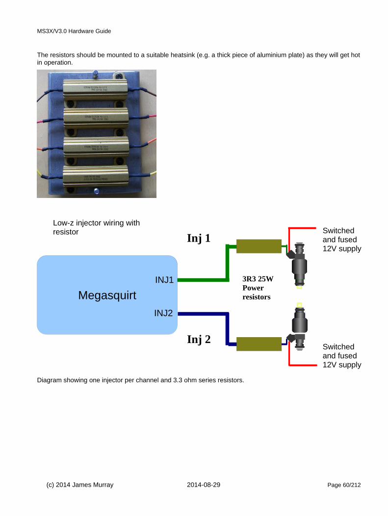
MS3X/V3.0 Hardware Guide
The resistors should be mounted to a suitable heatsink (e.g. a thick piece of aluminium plate) as they will get hotin operation.
Diagram showing one injector per channel and 3.3 ohm series resistors.
(c) 2014 James Murray 2014-08-29 Page 60/212
Megasquirt
INJ2
INJ1
Inj 1Switched and fused 12V supply
Switched and fused 12V supply
Inj 2
Low-z injector wiring with resistor
3R3 25W Power resistors

MS3X/V3.0 Hardware Guide
4.10.2.5 Batch-fire - low impedance injectors - Peak and hold
Aftermarket peak and hold controllers are available, these take the low-side injector output from the Megasquirt and provide the required peak and hold drive for the injectors. Typically this is a peak to 4A and then a hold at 1A.
Refer to supplier's documentation for exact wiring - the following diagram is representative only.
4.10.2.6 Sequential - high impedance injectors (12-16 Ohms)
These injectors can be directly connected to the Megasquirt. No need for injector resistors or external drivers.
Up to 2 injectors per channel may be connected.
Injectors are wired in firing order. Inj A is always #1, Inj B is second cylinder in firing order etc.
(c) 2014 James Murray 2014-08-29 Page 61/212
MegasquirtINJ2
INJ1
Switched and fused 12V supply
Peak & Hold wiring
4 wayPeak
& Hold
Switched and fused 12V supply
4 wayPeak
& Hold
Meg
asqu
irt
INJ A
Switched and fused 12V supply
High-z injector wiring
INJ B
INJ C
INJ D
INJ E
INJ F
INJ G
INJ H

MS3X/V3.0 Hardware Guide
4.10.2.7 Sequential - low impedance injectors (less than 3 Ohms)
These injectors can be used, with a few connection options.
• Injector resistors
• External peak-and-hold adapter
4.10.2.8 Sequential - low impedance injectors - Injector Resistors
This method has been used by many OEMs as a simple approach to driving low-z injectors. The installer has the option of installing a power resistor (typically with a 20 to 40 watt rating) in series with each injector (in effect converting them to high impedance.)
The series resistors will slow down the opening of the injector slightly, so it is suggested that the resistance of the resistors be kept to a minimum but staying within the 5A limit of each injector channel. One resistor must be used for each injector - do not try to share resistors.
For typical 2.5ohm low impedance injectors, the following resistances can be used
Number of injectors per channel Resistor value
1 3.3 ohm
2 4.7 ohm
The resistors should be mounted to a suitable heatsink (e.g. a thick piece of aluminium plate) as they will get hotin operation.
(c) 2014 James Murray 2014-08-29 Page 62/212

MS3X/V3.0 Hardware Guide
Diagram showing two channels with one injector per channel and 3.3 ohm series resistors. Repeat for Inj C-H asrequired.
4.10.2.9 Sequential - low impedance injectors - Peak and hold
Aftermarket peak and hold controllers are available, these take the low-side injector output from the Megasquirt and provide the required peak and hold drive for the injectors. Typically this is a peak to 4A and then a hold at 1A.
Refer to supplier's documentation for exact wiring - the following diagram is representative only.
4.10.3 Staged injectionStaged injection is a method that allows for two sets of injectors to give a better dynamic range of fueling - more precise control at idle, but still flowing enough fuel at full load. Typically, at low load, idle or cruise only the smaller primary injectors are in operation. At higher fuel demands, the secondary injectors are enabled.
(c) 2014 James Murray 2014-08-29 Page 63/212
Megasquirt
INJ B
INJ A
Switched and fused 12V supply
Switched and fused 12V supply
Low-z injector wiring with resistor
3R3 25W Power resistors
Switched and fused 12V supply
Peak & Hold wiring
4 wayPeak
& Hold
Switched and fused 12V supply
4 wayPeak
& Hold
Meg
asqu
irt
INJ A
INJ B
INJ C
INJ D
INJ E
INJ F
INJ G
INJ H

MS3X/V3.0 Hardware Guide
When using "Staged Injection" there are a number of wiring combinations possible.
• Primaries on sequential MS3X outputs, secondaries on sequential MS3X outputs (up to 4cyl only)
• Primaries on sequential MS3X outputs, secondaries as batch fire
• Primaries on batch 1, secondaries on batch 2.
See the TunerStudio reference manual for configuration details.
4.10.4 More wiring examplesSee section 9.1 for example wiring diagrams for seuquential fuel and spark.
(c) 2014 James Murray 2014-08-29 Page 64/212

MS3X/V3.0 Hardware Guide
5: Ignition System - fundamentalsThe ignition system comprises both the crank and cam tach inputs and the ignition outputs to drive coils. There are many different combinations possible, this chapter will describe some of the possibilities.
Note: A tach input is required on ALL installs including fuel-only.
5.1 Safety Notes
Ignition systems produce dangerous voltages in excess of 30,000V. Take care to avoid shock.
5.2 Crank and Cam tach inputsThe tach input is one of the most important signals going into the Megasquirt and correct system operation is not possible until the tach input is correctly installed and configured. Until the Megasquirt reads the correct RPM, nothing else will work.
Even if you are starting with fuel injection only (not controlling ignition) you must still provide the Megasquirt witha tach input - see coil negative triggering in section 5.2.1
The MS3X/V3.0 as standard has a two tach inputs. You must customize the board internally to select whether this input connects to the opto-isolator input for coil-negative triggering, or to the 'universal' tach input circuit.
There are many different options for tach input and this is probably one of the largest areas of difficulty with any after-market EFI install. The firmware contains software decoders to suit many stock installs using original sensors. If your engine is supported, then this is the recommended approach.
Two key pieces of information you need to know are:
• Sensor type(s)
• Toothed wheel pattern
The sensor types fall into a few basic families of sensors and the right way to use the sensor depends more on the type rather than the particular vehicle or manufacturer. There are also a few "special" systems in use from the eighties that combine a sensor input with an ignition driver output in one module. These will be discussed
(c) 2014 James Murray 2014-08-29 Page 65/212
2 wire typically VR, 3 wire hall
12V
su
pply
if
hal
l sen
sor
Screen grounded at Megasquirt
24
2

MS3X/V3.0 Hardware Guide
later - Ford TFI, Ford EDIS, GM HEI, GM DIS.
If you are considering an after-market, non-OEM sensor you must ENSURE that it has a suitable temperature rating. Typically engines run at around 100°C/212°F so a minimum of 105°C rating is required, 125°C desired. Do not consider using 85°C rated parts around the engine as they will degrade and cause you trouble. Be awareof heat radiated from exhaust components - these can overheat sensors and cause failure.
5.2.1 Coil Negative InputFor fuel-only installs it is possible to obtain a tach in trigger from the negative terminal of a single coil.
Opto-isolator (for coil negative fuel-only triggering):
a) Fit a 36V Zener Diode in reverse into position D2. Note, the Zener Diode must be fitted backwards, so the strip on the diode is the opposite end to the stripe on the main board! (This component is part of the kit from good suppliers)
b) Ensure C30 is fitted. (This is needed for noise elimination)
c) Ensure D1 is fitted.
d) Ensure R12 is fitted (390R 1/2W)
e) Solder a jumper from XG1 to XG2. In exceptionally noisy situations it might be required to remove that jumperand instead runs XG1 out through a spare connection on the DB37 and through the wiring harness direct to the engine.
f) Link TACHSELECT to OPTOIN
g) Link TSEL to OPTOOUT
See also section 6.1 for fuel only setup.
(c) 2014 James Murray 2014-08-29 Page 66/212
Tach in (DB37 pin 24)
Coil negative (not CDI)

MS3X/V3.0 Hardware Guide
5.2.2 VR (magnetic) sensor input
The VR sensor is a very commonly used sensor. Usually it is seen as a two wire sensor although some manufacturers install a screen on the cable, so yours may have three wires. In CAS (crank angle sensor) units amultiplug may be used to combine multiple sensors. The sensor itself generates an AC voltage when a piece of steel (the trigger) moves past it. Non-ferrous trigger wheels will not work. The voltage varies from less than a volt during cranking to tens of volts at higher revs.
Typically it is suggested that the magnetic tip of the sensor is around the same size as the teeth on the wheel.
In order to use a VR sensor a "conditioner" circuit is required to convert the AC voltage into a DC square wave signal while retaining the timing information. The Megasquirt has this conditioner built in. The two signal wires from the VR sensor are connected to Tach-in and GND at the Megasquirt. Ideally use a screened twisted pair cable and connect the screen to sensor ground at the Megasquirt end only.
The mainboard needs to be set as follows:
VR Input for VR (magnetic) sensor
a) Solder a link between VRIN and TACHSELECT
(c) 2014 James Murray 2014-08-29 Page 67/212
Screened cable
VR+
VR-
Shield
VR sensor
Sensor ground at Megasquirt
Tach in (DB37 pin 24)

MS3X/V3.0 Hardware Guide
b) Solder a wire between VrOUT and TSEL
c) With a small screwdriver, turn the pots, R52 and R56, about 12 turns anticlockwise (sometimes you may feel a "click" when the end position is reached, they can't be damaged by turning too far.) This sets them up for mostVR sensors.
Some installs may find it necessary to install a resistor inline with the VR+ wire to reduce the signal voltage at higher RPMs. Typically a 10k 1/4W resistor is sufficient.
5.2.3 Hall sensor inputThe Hall sensor is another commonly used category of sensor. These are almost exclusively a three wire sensor. In CAS (crank angle sensor) units a multi-plug may be used to combine multiple sensors. The sensor itself acts like a switch to ground in the presence of a magnetic field. Hall sensors are commonly seen in distributors where vanes or shutters mask off the magnetic field causing the sensor to rapidly switch on or off at the edge of the vane. Another way that a hall sensor can be used is with a "flying magnet" installed on a rotatingpart of the engine (crank, cam sprocket etc.). As the magnet passes the hall sensor, the output switches to ground.
The most common OEM arrangement for a hall sensor is within a distributor. The vanes in the distributor rotate and block or unblock a magnet.
With no vane between the magnet and sensor - the output is grounded.
With a vane between the magnet and sensor - the output is inactive.
(c) 2014 James Murray 2014-08-29 Page 68/212
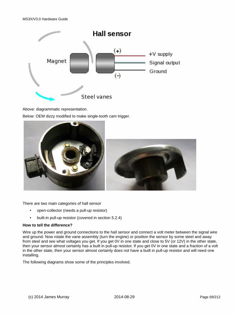
MS3X/V3.0 Hardware Guide
Above: diagrammatic representation.
Below: OEM dizzy modified to make single-tooth cam trigger.
There are two main categories of hall sensor
• open-collector (needs a pull-up resistor)
• built-in pull-up resistor (covered in section 5.2.4)
How to tell the difference?
Wire up the power and ground connections to the hall sensor and connect a volt meter between the signal wire and ground. Now rotate the vane assembly (turn the engine) or position the sensor by some steel and away from steel and see what voltages you get. If you get 0V in one state and close to 5V (or 12V) in the other state, then your sensor almost certainly has a built in pull-up resistor. If you get 0V in one state and a fraction of a volt in the other state, then your sensor almost certainly does not have a built in pull-up resistor and will need one installing.
The following diagrams show some of the principles involved.
(c) 2014 James Murray 2014-08-29 Page 69/212

MS3X/V3.0 Hardware Guide
The hall sensor requires a supply voltage which is usually 12V from a fused 12V supply or 5V from the TPSREFoutput of the Megasquirt. The sensor is then grounded at the Megasquirt sensor ground and the signal wire connects to the Tach input. A pull-up resistor is required in the wiring harness or inside the Megasquirt.
(c) 2014 James Murray 2014-08-29 Page 70/212

MS3X/V3.0 Hardware Guide
VR Input with pullup for hall sensors, LS2/58X, optical sensors or points
a) Solder a link between VRIN and TACHSELECT
b) Solder a wire between VrOUT and TSEL
c) Install a 1k resistor (any value 470R - 2k2 is likely OK) in the proto area. Connect one end to the 5V hole and join the other end to VRIN with a jumper wire.
d) With a small screwdriver, turn the pots, R52 and R56, about 12 turns anticlockwise (sometimes you may feel a "click" when the end position is reached, they can't be damaged by turning too far.) and then turn R56 back about 6 turns clockwise.
(c) 2014 James Murray 2014-08-29 Page 71/212
Screened cable - if used
SignalGroundShield
Open-collector hall / geartooth / optical sensor
Tach in (DB37 pin 24)
Sensor ground at Megasquirt
12V or 5V power to sensorPWR
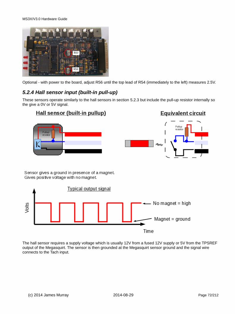
MS3X/V3.0 Hardware Guide
Optional - with power to the board, adjust R56 until the top lead of R54 (immediately to the left) measures 2.5V.
5.2.4 Hall sensor input (built-in pull-up)These sensors operate similarly to the hall sensors in section 5.2.3 but include the pull-up resistor internally so the give a 0V or 5V signal.
The hall sensor requires a supply voltage which is usually 12V from a fused 12V supply or 5V from the TPSREFoutput of the Megasquirt. The sensor is then grounded at the Megasquirt sensor ground and the signal wire connects to the Tach input.
(c) 2014 James Murray 2014-08-29 Page 72/212

MS3X/V3.0 Hardware Guide
VR Input for logic input e.g. TFI, EDIS, GMDIS, LS1/24X, modules, hall sensor with built-in pullup
a) Solder a link between VRIN and TACHSELECT
b) Solder a wire between VrOUT and TSEL
c) With a small screwdriver, turn the pots, R52 and R56, about 12 turns anticlockwise (sometimes you may feel a "click" when the end position is reached, they can't be damaged by turning too far.)
d) Turn R56 back about 6 turns clockwise.
Optional - with power to the board, adjust R56 until the top lead of R54 (immediately to the left) measures 2.5V.
(c) 2014 James Murray 2014-08-29 Page 73/212
Screened cable - if used
SignalGroundShield
Hall / geartooth / logic / optical sensor
Tach in (DB37 pin 24)
Sensor ground at Megasquirt
12V or 5V power to sensorPWR
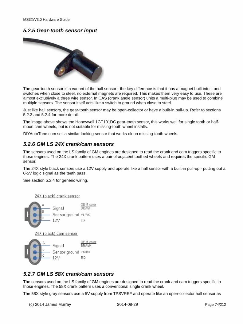
MS3X/V3.0 Hardware Guide
5.2.5 Gear-tooth sensor input
The gear-tooth sensor is a variant of the hall sensor - the key difference is that it has a magnet built into it and switches when close to steel, no external magnets are required. This makes them very easy to use. These are almost exclusively a three wire sensor. In CAS (crank angle sensor) units a multi-plug may be used to combine multiple sensors. The sensor itself acts like a switch to ground when close to steel.
Just like hall sensors, the gear-tooth sensor may be open-collector or have a built-in pull-up. Refer to sections5.2.3 and 5.2.4 for more detail.
The image above shows the Honeywell 1GT101DC gear-tooth sensor, this works well for single tooth or half-moon cam wheels, but is not suitable for missing-tooth wheel installs.
DIYAutoTune.com sell a similar looking sensor that works ok on missing-tooth wheels.
5.2.6 GM LS 24X crank/cam sensorsThe sensors used on the LS family of GM engines are designed to read the crank and cam triggers specific to those engines. The 24X crank pattern uses a pair of adjacent toothed wheels and requires the specific GM sensor.
The 24X style black sensors use a 12V supply and operate like a hall sensor with a built-in pull-up - putting out a0-5V logic signal as the teeth pass.
See section 5.2.4 for generic wiring.
5.2.7 GM LS 58X crank/cam sensorsThe sensors used on the LS family of GM engines are designed to read the crank and cam triggers specific to those engines. The 58X crank pattern uses a conventional single crank wheel.
The 58X style gray sensors use a 5V supply from TPSVREF and operate like an open-collector hall sensor as
(c) 2014 James Murray 2014-08-29 Page 74/212

MS3X/V3.0 Hardware Guide
they require a pull-up resistor.
See section 5.2.3 for generic wiring.
5.2.8 Optical sensor
The optical sensor is another commonly used category of sensor. These are almost exclusively a three wire sensor. In CAS (crank angle sensor) units a multi-plug may be used to combine multiple sensors. The sensor itself acts like a switch to ground when light shines through the trigger disc. Optical sensors are commonly seen in distributors where vanes or shutters block the light causing the sensor to rapidly switch off and back on when light is present again. A pull-up resistor is almost certainly required.
See section 5.2.3 for wiring.
Note: One OEM application for optical sensors is the Mitsubishi/Nissan/Optispark CAS. Megasquirt-2 does not support the 360 slit "hi-res" tach input from these CASes, see the specific manual section for configuration details.
5.2.9 Distributor points inputNOTE: re-phasing a distributor can be quite awkward - installing a toothed-wheel for tach input is strongly recommended instead.
It is possible to convert a points distributor to give a tach input to Megasquirt and have control of your timing. In this case the points now only provide a tach signal and the Megasquirt is used to control the coil. Most conventional points distributors have a mechanical advance (weights) and a vacuum canister. In the original system these change the timing depending on engine RPM and load. Now that Megasquirt will be controlling thetiming you will need to lock out these mechanisms in your distributor and likely change the phasing.
Set the engine to approx 10BTDC. Rotate the distributor so that the point are just opening when the engine rotates forwards.
Now set the engine to approx 25BTDC - the rotor arm needs to be pointing directly to a tower on the distributor cap.
(c) 2014 James Murray 2014-08-29 Page 75/212

MS3X/V3.0 Hardware Guide
You will likely need to make mechanical changes (cutting, bolting, welding) inside the distributor to achieve this.
With incorrect rotor arm phasing you will very likely end up with cross-firing to the wrong cylinder.
The low-tension side of the coil must be disconnected from the distributor and is now controlled by the Megasquirt (see ignition outputs section.)
The points are grounded within the distributor and the points terminal is connected to the Megasquirt tach input.
A pull-up resistor is required in the wiring harness or inside the Megasquirt.
Set mainboard as per section 5.2.3.
5.2.10 Combined Ignition module (TFI, EDIS, HEI, GMDIS)Some ignition modules, particularly from the 1980s combine the tach input and coil driving ignition output within one module. All of them supply a simple square wave digital signal to the Megasquirt and should be connected to the Tach input.
It is important to be aware that while Ford EDIS and GM DIS both have special toothed wheels, the module handles all the decoding and presents a signal to the Megasquirt that looks like a distributor input. With these two modules, the Megasquirt does not know or care how many teeth are actually on thewheel, so do not use the "toothed wheel" setting. This also means that normally you cannot use sequential fuel with these systems as no engine position information is available to the Megasquirt.
Full configuration details for these specific installs are covered in the section 6.
5.2.11 Nissan CASThe Mitsubishi CASes used on many Nissans and GM LT1 Optispark use a dual optical pickup and a trigger disc with a high-resolution series of 360 outer slits and a low-resolution series of inner slots - one per cylinder.
(c) 2014 James Murray 2014-08-29 Page 76/212
Points
Tach in (DB37 pin 24)
Megasquirt
Tach in(crank/cam)
Ignition out
Ignition module
Tach in
IGN
Tach output
Spark input
* exact connection depends on module - see specific section

MS3X/V3.0 Hardware Guide
Nissan CAS GM Optispark
The Megasquirt-3 code supports the high-resolution outer signal. Both hi-res and low-res must be connected. Specific details are in the GM Optispark, Nissan RB25 and Nissan SR20 ignition sections. The hi-res tach input needs to be connected to PT4 through the MS3X board.
Optionally, the low-resolution inner signal alone can be used with a single coil and distributor in "Basic Trigger" mode.
When using the stock trigger disc and "Basic Trigger", the high-resolution outer track is not used. The low-resolution inner track is connected to the Tach input.
Set the mainboard as per section 5.2.3
Optispark.
(c) 2014 James Murray 2014-08-29 Page 77/212
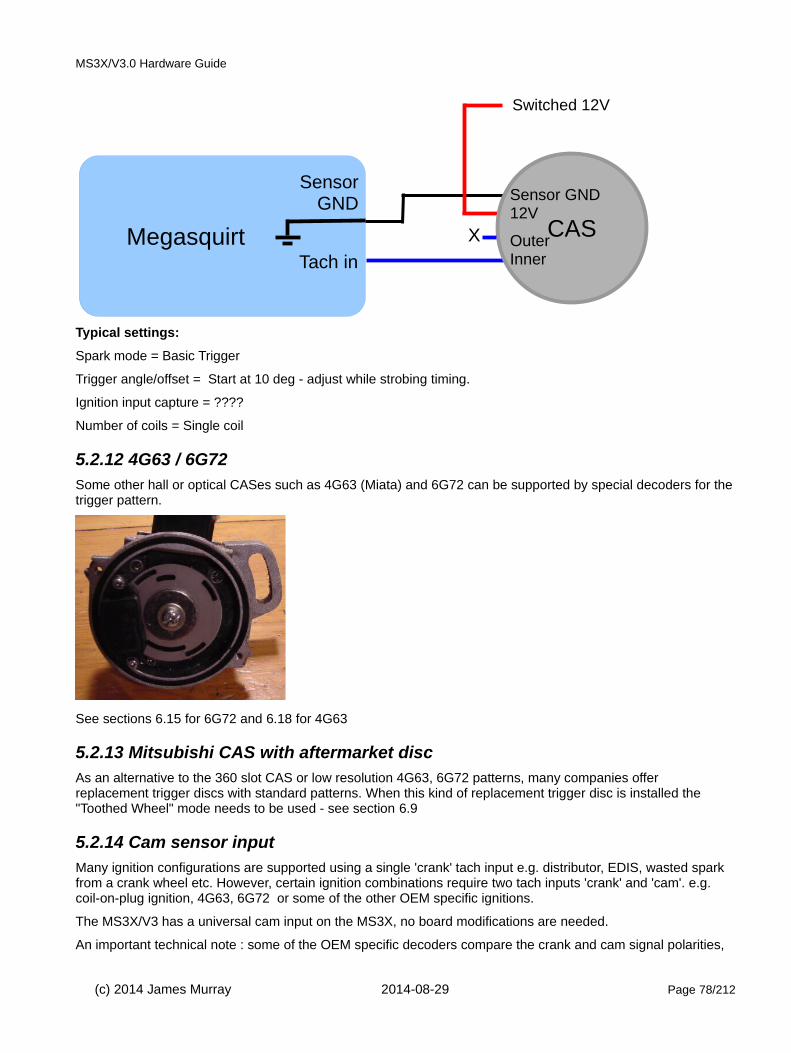
MS3X/V3.0 Hardware Guide
Typical settings:
Spark mode = Basic Trigger
Trigger angle/offset = Start at 10 deg - adjust while strobing timing.
Ignition input capture = ????
Number of coils = Single coil
5.2.12 4G63 / 6G72Some other hall or optical CASes such as 4G63 (Miata) and 6G72 can be supported by special decoders for thetrigger pattern.
See sections 6.15 for 6G72 and 6.18 for 4G63
5.2.13 Mitsubishi CAS with aftermarket discAs an alternative to the 360 slot CAS or low resolution 4G63, 6G72 patterns, many companies offer replacement trigger discs with standard patterns. When this kind of replacement trigger disc is installed the "Toothed Wheel" mode needs to be used - see section 6.9
5.2.14 Cam sensor inputMany ignition configurations are supported using a single 'crank' tach input e.g. distributor, EDIS, wasted spark from a crank wheel etc. However, certain ignition combinations require two tach inputs 'crank' and 'cam'. e.g. coil-on-plug ignition, 4G63, 6G72 or some of the other OEM specific ignitions.
The MS3X/V3 has a universal cam input on the MS3X, no board modifications are needed.
An important technical note : some of the OEM specific decoders compare the crank and cam signal polarities,
(c) 2014 James Murray 2014-08-29 Page 78/212
Megasquirt
SensorGND
Tach in
CAS
Sensor GND12V
OuterInner
Switched 12V
X

MS3X/V3.0 Hardware Guide
the main tach input inverts the incoming signal, so the added cam tach input must do the same. The instructionshere respect that requirement.
MS3X card cam configuration.
5.2.14.1 Cam sensor input - VR/magnetic sensor
a) Ensure JP7 is not jumpered.b) Turn both pots (R11 and R32) 7 turns anti-clockwise (sometimes you may feel a "click" when the end position is reached, they can't be damaged by turning too far.)
5.2.14.2 Cam sensor input - open-collector hall sensor / optical sensor
a) Install the jumper across JP7b) Turn both pots (R11 and R32) 7 turns anti-clockwise (sometimes you may feel a "click" when the end position is reached, they can't be damaged by turning too far.)c) Then turn the top one (R11) 3 turns clockwise.
Optional - with power on, adjust R11 until the voltage at ZC TESTPOINT is 2.5V
5.2.14.3 Adding a cam sensor input - hall or logic sensor
a) Ensure JP7 is not jumpered.b) Turn both pots (R11 and R32) 7 turns anticlockwise (sometimes you may feel a "click" when the end position is reached, they can't be damaged by turning too far.)c) Then turn the top one (R11) 3 turns clockwise.
Optional - with power on, adjust R11 until the voltage at ZC TESTPOINT is 2.5V
(c) 2014 James Murray 2014-08-29 Page 79/212
R11
R32

MS3X/V3.0 Hardware Guide
5.3 Ignition outputsThe MS3X output has provision for eight sequential logic spark outputs. The mainboard has provision for a single high-current ignition output as standard.
On regular ignition installs, the ignition outputs must be connected in firing order sequence.
e.g. a 4-cyl engine with coil-on-plug and a 1-3-4-2 firing order would connect A=1, B=3, C=4, D=2
Rotary engines are wired differently - refer to the specific section.
Double check your Spark Output setting - this is a critical !
Setting it incorrectly could result in melted coils.
It is strongly advised that ignition coils are powered from the fuel-pump relay. This ensures that the coils can only be powered when the engine is running.
5.3.1 Building ignition outputs
5.3.1.1 High current output (one)
This provides a single high-current ignition output suitable for directly driving one inductive coil.
Internally, the follow is required:
- BIP373 (marked as 30115) needs to be installed in Q16 with a mica insulator.
- Jumper IGBTOUT-IGN.
- Connect a 330R 1/4W resistor between IGBTin and the top of R26.
- Ensure R57 is absent.
- Ensure R43 is fitted or jumpered.
Typical settings
Spark Output = Going High
Dwell Type = Standard Dwell
Dwell ~ 3ms for a standard coil
5.3.1.2 Additional mainboard ignition outputs
These are not covered in this manual as the preference is to use the sequential MS3X outputs. See the
(c) 2014 James Murray 2014-08-29 Page 80/212
Megasquirt
IGN(36)
Fused +12V from fuel pump relay
(With BIP373 wired to top of R26)

MS3X/V3.0 Hardware Guide
MS3base/V3.0 Hardware manual.
5.3.2 Logic coilsThese coils can directly accept the 0-5V logic level signal from the Megasquirt. The contain an ignition driver and a coil within the package.
LS1 (left), LS2 middle), Truck (right) coils
A dwell figure of 3.5ms is advised for LS1 coils.(was 4.5)
Note that some coils have a built-in over-dwell protection feature. If given too much dwell the coil will automatically spark. This can give a dangerous advanced spark. Be sure to strobe your timing at high revs to ensure this is not happening.
Set the Spark Output to Going High.
(c) 2014 James Murray 2014-08-29 Page 81/212

MS3X/V3.0 Hardware Guide
A dwell figure of 3.5ms is advised for LS2 coils. (was 4.5)
Note that some coils have a built-in over-dwell protection feature. If given too much dwell the coil will automatically spark. This can give a dangerous advanced spark. Be sure to strobe your timing at high revs to ensure this is not happening.
Set the Spark Output to Going High.
D585 truck coil
Pin-outA = Power ground to engine blockB = Signal ground (connect to sensor ground)C = Spark input signal D = 12V supply
Common colors:A = blackB = brownC = varies per coilD = pink
A dwell figure of 3.5ms is advised for truck coils.
Note that some coils have a built-in over-dwell protection feature. If given too much dwell the coil will automatically spark. This can give a dangerous advanced spark. Be sure to strobe your timing at high revs to ensure this is not happening.
Set the Spark Output to Going High.
LS coilpack multi-plug
Pin-out and typical colorsA = black = power groundB = red = signal coil WC = green = signal coil XE = brown = signal groundF = light blue = signal coil YG = purple = signal coil ZH = pink = 12V supply
(c) 2014 James Murray 2014-08-29 Page 82/212
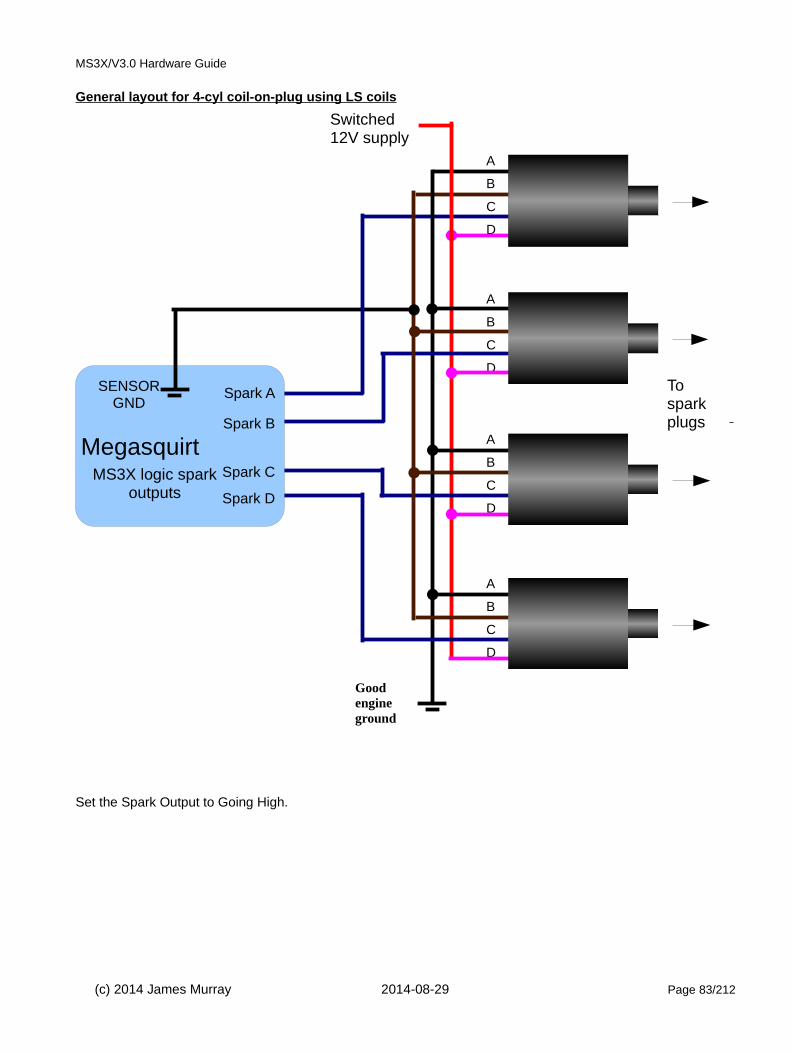
MS3X/V3.0 Hardware Guide
General layout for 4-cyl coil-on-plug using LS coils
Set the Spark Output to Going High.
(c) 2014 James Murray 2014-08-29 Page 83/212
Megasquirt Spark C
Spark D
Spark B
Spark ASENSOR GND
Tosparkplugs
A
B
C
D
Switched 12V supply
A
B
C
D
A
B
C
D
A
B
C
D
Good engine ground
MS3X logic spark outputs

MS3X/V3.0 Hardware Guide
IGN1A logic coil
A - Ignition signal from Megasquirt
B - Logic ground, connect to Megasquirt sensor ground
C - Spark wire ground, connect to cylinder head
D - Power ground, connect to battery negative
E - 12 volt power (switched and fused)
Set the Spark Output to Going High.
This is a high energy aftermarket logic coil available from DIYAutoTune.com.
0 004- 402 001 - single logic coil
Pin-out
1 = Power Ground (Brown)
2 = Spark input signal 1 (Black/Red)
3 = 12V supply (Black)
Set the Spark Output to Going High.
Fitted to many VAG vehicles including 2.0 litre mk3 Golfs 1993-1999. Designed to be used as a single coil with adistributor.
Intermotor 12916
(c) 2014 James Murray 2014-08-29 Page 84/212
Switched 12V supply
Megasquirt
Good engine ground
3
2
1Spark A
MS3X logic spark output
Ignitor +
coil
Todistributor

MS3X/V3.0 Hardware Guide
032 905 106B - 4 tower wasted spark logic coil
Pin-out
1 = Spark input signal 1
2 = 12V supply
3 = Spark input signal 2
4 = Power Ground
Set the Spark Output to Going High.
The connector is 1J0 973 724
This cost effective OEM logic wasted coil has a built-in ignitor.
Fitted to many VAG vehicles including 1.6 litre mk4 Golfs.
Intermotor 12919
(c) 2014 James Murray 2014-08-29 Page 85/212
Switched 12V supply
Megasquirt
Good engine ground
4
1
To sparkplugs 2&3
Spark A
Spark B
032 9
06
10 6
B
4 3 2 1
To sparkplugs 1&4
MS3X logic spark outputs

MS3X/V3.0 Hardware Guide
06A905097 - 4 way logic coil
4 way logic coil from VW Golf / Jetta, Skoda Octavia
Uses part numbers 0040102029, 06A905097, 06A905104, ZSE029
The connector is a polarised Bosch Kompact 6 way. 1J0973726 - 6 Way Sealed Female Connector. The contacts are 2.8 mm
Set the Spark Output to Going High.
Pin-out
1 = Power Ground
2 = Spark input signal 1
3 = Spark input signal 2
4 = Spark input signal 3
5 = Spark input signal 4
6 = 12V supply
(c) 2014 James Murray 2014-08-29 Page 86/212
06A 905 097
Switched 12V supply
Megasquirt
Goodengineground
1
6
Tosparkplugs
MS3X logic spark outputs
Spark B
Spark A
Spark C
Spark D

MS3X/V3.0 Hardware Guide
06B 905 115 - 4 wire logic COP
VAG P/N 06B 905 115 COPs: used on VW 1.8t and may other VAG cars.
Pin 1: Connects to Pin 1 on all other coils and then to +12v ignition feed (or fuel pump relay)
Pin 2: Signal ground (connect to engine block)
Pin 3: Spark Signal from Megasquirt
Pin 4: Power ground (connect to engine block)
Earlier than 2001 coils, PN - 06B 905 115, 06B 905 115 rev B and E.
These have an input resistance of ~1k and should work OK with the Megasquirt outputs.
Cranking dwell = 4.0ms Running dwell= 3.0ms
Set the Spark Output to Going High.
Later than 2001 coils, PN 06B 905 115 rev L and R have a low input resistance. The MS3X logic outputs outputs cannot drive these coils directly - see the MS3base/V3.0 manual for example circuits or use an external buffer designed for these coils.
Aside from these specific examples, there are many generic 3, 4, 5 wire COPs that can be used with the Megasquirt.
Before using an "unknown" coil it is necessary to check the resistance to ground on the input.
Using a multimeter set to resistance, check between the Spark Signal Input and Signal Ground.
If you have a reading of say ~1k then the Megasquirt MS3X outputs can be used directly.
(c) 2014 James Murray 2014-08-29 Page 87/212

MS3X/V3.0 Hardware Guide
3-wire COPs are ambiguous, many are high-current (needing an ignitor), some may be logic level with a built in driver. Perform a resistance check on the signal input to confirm. High current will have an input resistance to 12V of a few ohms only.
COPs with 4 or 5 wires have a built in amplifier (ignitor) and can typically be directly connected to the MS3X outputs.
Set the Spark Output to Going High.
5.3.3 Amplifiers (ignitor, power transistor, ignition module)An ignition amplifier module takes a 5V logic signal from the Megasquirt and drives a high-current ignition coil.
This can be advantageous to keep ignition noise outside of the Megasquirt, or your engine may already have one.
There are many different modules available on the market with 1, 2, 4 ignition channels.
Bosch style 1, 2, 4 channel ignitors and Quadspark 4 channel ignitor.
Bosch 0 227 100 124
Cross references Intermotor 15015.
This single channel module can be used to drive a single high-current coil. Dwell is controlled by the Megasquirt.
Set the Spark Output to Going High.
Pin-out
1 = Coil negative output
2 = Power Ground
3 = Input screen (if used)
4 = 12V supply
(c) 2014 James Murray 2014-08-29 Page 88/212

MS3X/V3.0 Hardware Guide
5 = Spark input signal
6 = NC
(7 = NC)
Bosch 0 227 100 200
Cross references Intermotor 15867.
This dual channel module can be used to drive a high-current wasted spark coil-pack for full spark control on a four-cylinder engine, or a pair of COPs on a two-cylinder engine. Dwell is controlled by the Megasquirt.
Set the Spark Output to Going High.
Pin-out
1 = Coil negative output 1
2 = Spark input signal 1
3 = NC
4 = Power Ground
5 = NC
6 = Coil negative output 2
7 = Spark input signal 2
(c) 2014 James Murray 2014-08-29 Page 89/212

MS3X/V3.0 Hardware Guide
Bosch 0 227 100 211
Cross references Intermotor 15857. Typically used on VW Golf 1.8t yr 2000.
This four channel module is typically used to drive four COPs on a four-cylinder engine, it could also be used to drive a pair of high-current wasted spark coil-packs for full spark control on an eight cylinder engine. Dwell is controlled by the Megasquirt.
Set the Spark Output to Going High.
Pin-out (5 pin)
1 = Spark input signal 1
2 = Spark input signal 2
3 = Power Ground
4 = Spark input signal 3
5 = Spark input signal 4
Pin-out (4 pin)
1 = Coil negative output 4
2 = Coil negative output 3
3 = Coil negative output 2
4 = Coil negative output 1
(c) 2014 James Murray 2014-08-29 Page 90/212

MS3X/V3.0 Hardware Guide
Quadspark
This aftermarket four channel module operates similarly to the Bosch 211, but is typically more cost effective.
Pin-out Thickness Function
Yellow 20 gauge Spark Input A (from Megasquirt)
White 16 gauge Spark Output A (to coil negative)
Orange 20 gauge Spark Input B (from Megasquirt)
Pink 16 gauge Spark Output B (to coil negative)
Dark green 20 gauge Spark Input C (from Megasquirt)
Light Green 16 gauge Spark Output C (to coil negative)
Blue 20 gauge Spark Input D (from Megasquirt)
Violet 16 gauge Spark Output D (to coil negative)
Black 4 x 14 gauge Ground (to engine block or cylinder head)
(c) 2014 James Murray 2014-08-29 Page 91/212

MS3X/V3.0 Hardware Guide
Set the Spark Output to Going High.
The diagram shows connection to COPs, but the module can also be used to drive high current coilpacks (Ford, Chrysler etc.)
5.3.4 High current coilsThis type of coil requires a a high current driver as per section 5.3.1.1 or an amplifier as per section 5.3.3
(c) 2014 James Murray 2014-08-29 Page 92/212

MS3X/V3.0 Hardware Guide
Shown are conventional single coil, GM wasted spark coil, Ford wasted spark coil-pack, Renault 2-wire COP. All of these coils are high current coils and require an ignition amplifier module (ignitor) to connect to the Megasquirt.
Conventional coils and ''dumb' 2-wire COPs.
The connections are :
• switched/fused 12V supply
• output from ignitor. The resistance measured between the inputs will be a few ohms only.
Requires an ignitor or customization for high current outputs.
2 wire wasted spark coils - like the GM coil.
The connections are :
• switched/fused 12V supply
• output from ignitor. The resistance measured between the inputs will be a few ohms only.
Requires an ignitor or customization for high current outputs.
(c) 2014 James Murray 2014-08-29 Page 93/212
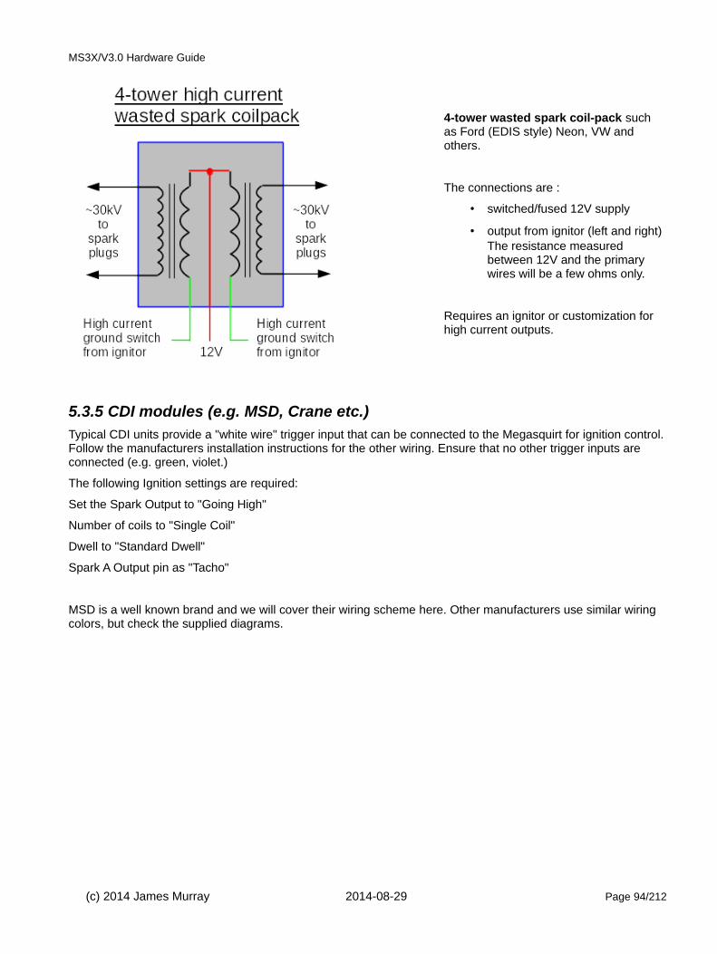
MS3X/V3.0 Hardware Guide
4-tower wasted spark coil-pack such as Ford (EDIS style) Neon, VW and others.
The connections are :
• switched/fused 12V supply
• output from ignitor (left and right)The resistance measured between 12V and the primary wires will be a few ohms only.
Requires an ignitor or customization for high current outputs.
5.3.5 CDI modules (e.g. MSD, Crane etc.)Typical CDI units provide a "white wire" trigger input that can be connected to the Megasquirt for ignition control.Follow the manufacturers installation instructions for the other wiring. Ensure that no other trigger inputs are connected (e.g. green, violet.)
The following Ignition settings are required:
Set the Spark Output to "Going High"
Number of coils to "Single Coil"
Dwell to "Standard Dwell"
Spark A Output pin as "Tacho"
MSD is a well known brand and we will cover their wiring scheme here. Other manufacturers use similar wiring colors, but check the supplied diagrams.
(c) 2014 James Murray 2014-08-29 Page 94/212
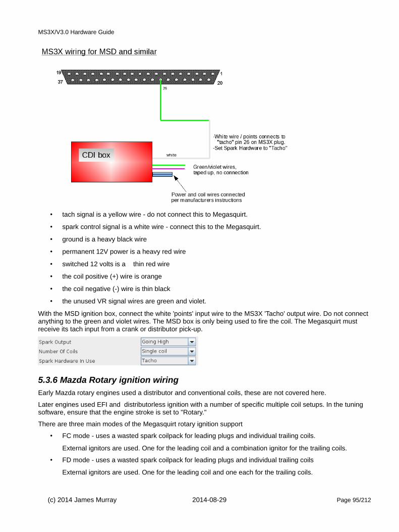
MS3X/V3.0 Hardware Guide
• tach signal is a yellow wire - do not connect this to Megasquirt.
• spark control signal is a white wire - connect this to the Megasquirt.
• ground is a heavy black wire
• permanent 12V power is a heavy red wire
• switched 12 volts is a thin red wire
• the coil positive (+) wire is orange
• the coil negative (-) wire is thin black
• the unused VR signal wires are green and violet.
With the MSD ignition box, connect the white 'points' input wire to the MS3X 'Tacho' output wire. Do not connect anything to the green and violet wires. The MSD box is only being used to fire the coil. The Megasquirt must receive its tach input from a crank or distributor pick-up.
5.3.6 Mazda Rotary ignition wiringEarly Mazda rotary engines used a distributor and conventional coils, these are not covered here.
Later engines used EFI and distributorless ignition with a number of specific multiple coil setups. In the tuning software, ensure that the engine stroke is set to "Rotary."
There are three main modes of the Megasquirt rotary ignition support
• FC mode - uses a wasted spark coilpack for leading plugs and individual trailing coils.
External ignitors are used. One for the leading coil and a combination ignitor for the trailing coils.
• FD mode - uses a wasted spark coilpack for leading plugs and individual trailing coils
External ignitors are used. One for the leading coil and one each for the trailing coils.
(c) 2014 James Murray 2014-08-29 Page 95/212
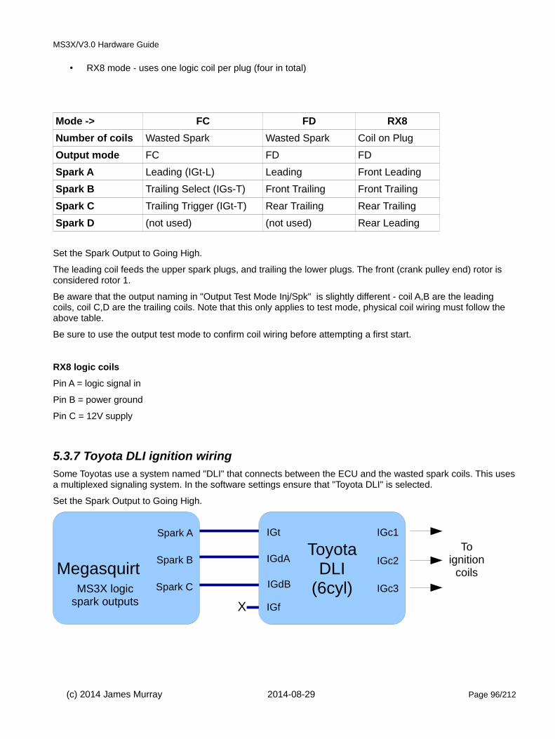
MS3X/V3.0 Hardware Guide
• RX8 mode - uses one logic coil per plug (four in total)
Mode -> FC FD RX8
Number of coils Wasted Spark Wasted Spark Coil on Plug
Output mode FC FD FD
Spark A Leading (IGt-L) Leading Front Leading
Spark B Trailing Select (IGs-T) Front Trailing Front Trailing
Spark C Trailing Trigger (IGt-T) Rear Trailing Rear Trailing
Spark D (not used) (not used) Rear Leading
Set the Spark Output to Going High.
The leading coil feeds the upper spark plugs, and trailing the lower plugs. The front (crank pulley end) rotor is considered rotor 1.
Be aware that the output naming in "Output Test Mode Inj/Spk" is slightly different - coil A,B are the leading coils, coil C,D are the trailing coils. Note that this only applies to test mode, physical coil wiring must follow the above table.
Be sure to use the output test mode to confirm coil wiring before attempting a first start.
RX8 logic coils
Pin A = logic signal in
Pin B = power ground
Pin C = 12V supply
5.3.7 Toyota DLI ignition wiringSome Toyotas use a system named "DLI" that connects between the ECU and the wasted spark coils. This usesa multiplexed signaling system. In the software settings ensure that "Toyota DLI" is selected.
Set the Spark Output to Going High.
(c) 2014 James Murray 2014-08-29 Page 96/212
Megasquirt Spark C
Spark B
Spark A
ToyotaDLI
(6cyl)IGdB
IGf
IGdA
IGt
X
IGc3
IGc2
IGc1
Toignition
coils
MS3X logicspark outputs
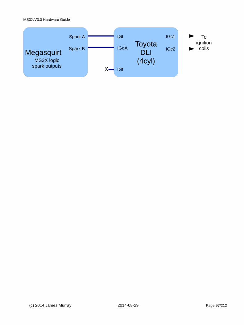
MS3X/V3.0 Hardware Guide
(c) 2014 James Murray 2014-08-29 Page 97/212
Megasquirt Spark B
Spark A
ToyotaDLI
(4cyl)IGf
IGdA
IGt
X
IGc2
IGc1 Toignition
coils
MS3X logicspark outputs

MS3X/V3.0 Hardware Guide
6: Ignition system - specific operating modesThe Megasquirt range supports many different tach input and output schemes including many OEM specific configurations.
For installations on engines without a supported tach input, a 36-1 trigger wheel on the crankshaft is the suggested setup.
Here are all of the 'spark modes' supported by the Megasquirt-3 product range and whether they support wastedspark (W/S) and COP/seq (coil-on-plug or sequential fuel) or not on a 4-stroke engine. 2-stroke engines only need a missing tooth wheel on the crankshaft for sequential fuel and spark.
Note that even if your trigger input could support COP/sequential, your ECU may not have enough outputs.
Spark Mode Caminput
needed?
W/S ? COP/seq ?
Applications
Fuel only N N N Various for fuel only (no spark control)
EDIS N Y N Early to mid 1990s Fords 4,6,8cyl
Basic trigger (distributor) N N N Widespread - HEI7, GMDIS, TFI, distributor
Trigger Return N N N Typically 1980s VW hall distributors
Toothed wheel"Missing tooth wheel" on crank"Missing tooth wheel" on cam"Missing tooth wheel" on crank + single tooth on cam"Dual wheel" non missing on crank+ single tooth on cam(36-1, 60-2, 4-1, 24/1, 24/2, 6-1 etc.)
Varies Varies Varies Ford, Bosch ECUs, very widespread. e.g. Ford, BMW, Vauxhall/Opel, many Japanesevehicles using Nippondenso CAS, GM LS2This is the most common selection covering thousands of installs.See detail pages for all variations
420A/Neon N Y If camused
420A Neons
36-2+2 N Y If camused
"Next Generation" Crank Chryslers including Jeep.
36-2-2-2 N Y If camused
Some Subaru and Mazda RX8 with stock trigger wheel phasing.
Subaru 6/7 Y Y Y Subarus flat fours
Miata 99-05 Y Y Y 1999-2005 Miata with 4 tooth crank trigger and 1,2 cam trigger.
6G72 Y Y Y Mitsubishi 3000GT/Galant
IAW Weber* Y Y Y Fiat / Cosworth engines with 4 tooth crank trigger and uneven distributor trigger.
CAS 4/1* Y Y Y Mitsubishi 4G91
4G63 Y Y Y Mitsubishi, Mazda Miata (MX5)
Twin trigger* (Y) Y N Bike engine with one reluctor and two trigger coils. Typically 4 cylinder wasted-spark.
Chrysler 2.2/2.5* N Y Y Distributor pickup. YMMV
(c) 2014 James Murray 2014-08-29 Page 98/212

MS3X/V3.0 Hardware Guide
Spark Mode Caminput
needed?
W/S ? COP/seq ?
Applications
Renix 44-2-2 N N If camused
Renault 4cyl, also V6 with 66-2-2-2
Suzuki Swift* N N N Distributor trigger wheel
Suzuki Vitara 2.0* N Y N Suzuki Vitara 2.0
Daihatsu 3cyl* N N N 3+1 cam trigger
Daihatsu 4cyl* N N N 4+1 cam trigger
VTR1000* N Y N 12-3 on crank
Rover#1* N ? If camused
Rover K Series 36-1-1
Rover#2* N ? If camused
Rover K Series 36-1-1-1-1
Rover#3* N ? If camused
Rover K Series 36-2-2
GM7X* N Y If camused
Direct from sensor bypassing GMDIS modules.
QR25DE* Y Y Y Nissan
Honda RC51* Y Y Y Also other versiants
Fiat 1.8 16V* Y Y Y
Optispark Y Y Y GM LT1 V8 engines
Nissan SR20 Y Y Y Stock high-res trigger disc
Nissan RB25 Y Y Y Stock high-res trigger disc
LS1 N Y If camused
GM LS1, LM7 etc. with 24X crank
YZF1000* N Y N
Honda Acura N Y If camused
VQ35DE* Y Y Y
Jeep 2000* Y Y Y
Jeep 2002* Y Y Y
Zetec VCT Y Y Y Ford Zetec with 4+1 cam pattern
Flywheel tri-tach* Y Y Y Audi engines with flywheel tooth sensor
2JZ VVTi* Y Y Y
Honda TSX/D17 Y Y Y
Mazda6 2.3 VVT* Y Y Y
(c) 2014 James Murray 2014-08-29 Page 99/212

MS3X/V3.0 Hardware Guide
Spark Mode Caminput
needed?
W/S ? COP/seq ?
Applications
Viper V10 Y Y Y 2nd Gen Viper V10
Viper V10 Gen1 Y Y Y 1st Gen Viper V10
Honda K24A2 Y Y Y
HD 32-2* N N Y Harley 45deg V-twin. Can use MAP sensor for phase detection or use a cam sensor.
Miata 36-2* N Y If camused
Flyin' Miata custom 36-2 wheel fitted to 99-05 engine.
Daihatsu 12+1 (N) Y Y Daihatsu EF-SE engine 3 cyl
* indicates a configuration that has received less usage in the field and may be less well proven. Proceed with caution or discuss with your supplier before using.
Running excessive timing under load will almost always cause severe engine damage suchas broken pistons.
It is essential that timing is confirmed with a timing-light on EVERY install.
NOTE! The tach input polarities provided in section 6 are for reference only and subject to review.
6.1 Coil negative for fuel onlyFor fuel-only installs it is possible to obtain a tach in trigger from the negative terminal of a single coil. Note that this won't work well on a wasted spark setup and must never be connected to a CDI type coil with a high primary voltage.
Coil negative input CANNOT be used for installs using the Megasquirt to control ignition.
Typical Settings
Spark mode = "Fuel only"
Set mainboard for Optoisolator input as per section 5.2.1
(c) 2014 James Murray 2014-08-29 Page 100/212
Tach in (DB37 pin 24)
Coil negative (not CDI)

MS3X/V3.0 Hardware Guide
6.2 Distributor pickupThe distributor is the traditional method of timing spark and distributing the high-tension spark voltage to individual spark plugs. Typically this used a set of breaker points, a condenser and a single ignition coil. Most distributors feature mechanical and vacuum advance systems to match spark timing somewhere close to optimal for different operating conditions. Later systems were "breakerless" and replaced the high-maintenance points with VR, hall or optical sensors. When combined with OEM fuel injection systems, the distributor may be "locked" in that there is no advance mechanism - the timing is controlled by the computer. Some OEM systems retain a distributor only for the high-tension spark distribution and use a trigger-wheel arrangement for tach input.
The first step in an install is to identify what kind of system is already fitted to your engine. Usually this is relatively straight forward to establish.
Note that Ford TFI, GMHEI7, GMHEI8 are special cases using a locked distributor and are covered in their own subsections.
6.2.1 Traditional vac/mech distributorFor distributor triggering you need one pulse per spark event. e.g. a normal distributor on a typical 4 stroke, 4 cylinder engine will have four lobes/teeth/vanes/slots in the distributor.
This applies to points, optical, VR, hall.
See section 5.2 for wiring details on the tach input.
Shown above is a "large cap" General Motors HEI4 distributor, typical on mid 1970s V8s.
(c) 2014 James Murray 2014-08-29 Page 101/212

MS3X/V3.0 Hardware Guide
Typical original arrangement
Typical arrangement with ECU ignition timing control and locked distributor
6.2.1.1 Input phasing
A typical distributor includes advance mechanisms which were originally used to control the timing. These are not used when using computer control and must be locked out to give a "locked" distributor.
Correctly modifying an old distributor to give a reliable tach input may well be more difficult than adding a crank trigger wheel and will never be as accurate. You are advised to consider installing a crank trigger wheel (e.g. 36-1) and sensor instead.
Early distributors such as points, HEI4, Duraspark etc, all have advance mechanisms built in. The HEI4 distributor shown above illustrates these mechanisms and is typical of pre-computer distributors. Similar distributors can be converted to computer control-
Remove ignition module (if present)
Connect pickup sensor (VR, hall, opto, points) to ECU.
Remove and weld up mechanical advance mechanism.
Remove vacuum canister.
Use remnants of vacuum advance mechanism to achieve correct input:output phasing.
You may be able to set the rotor output phasing FIRST and then rotate the baseplate to achieve the correct
(c) 2014 James Murray 2014-08-29 Page 102/212

MS3X/V3.0 Hardware Guide
input phasing.
Later engines may feature a distributor in conjunction with computer controlled timing - usually these distributor are "locked" from the factory and should already have good input and output phasing. (e.g. Ford TFI, GM HEI7/8, Bosch hall effect.) Align as per the factory manuals and determine how it is phased before you modify anything!
The crank angle at which the tach input triggers is of importance and needs to be configured in the Megasquirt. For best spark control there are some optimal and some disallowed crank angles.
A typical engine will have an operating advance range of say 10-50 BTDC timing (depending on engine type.) The trigger must not happen during this range of angles.
It can be really helpful to install timing tape on your crank pulley or temporarily mark on a range of angles.
For best accuracy at high revs or during transients, aim for the trigger to align at 60-90 BTDC. This also allows afull range of timing (including ATDC timing should you need it for boosted conditions.) This range of trigger angleis preferred for new installs.
For slightly better starting, but not quite such good running accuracy, aim for a trigger ~10BTDC or your desired cranking advance. This is the typical trigger angle for TFI and HEI7/8. You cannot retard timing later than the trigger angle. e.g. 9BTDC and lower are not possible with a 10 BTDC trigger angle.
The VR sensor input presents a simple pulse as the reluctor passes the sensor, this gives a timing position easily identified by eye. Use "Basic Trigger"
Rotate the engine to 60 BTDC (or 10 BTDC if chosen) and then align the distributor so the reluctor aligns with the center of the sensor.
Be aware of the allowable values for "trigger angle". Do not use angles in the disallowed range or you will have unreliable or unexpected operation.
(c) 2014 James Murray 2014-08-29 Page 103/212

MS3X/V3.0 Hardware Guide
Allowed high angles
Timing allowed in normal range (up to 5 degrees less than trigger angle.) Retarded ATDC timing possible.
Disallowed angles.
Do not use a trigger angle between 16 and 54 degrees.
Timing will not work correctly.
Distributor must be moved or re-phased.
Allowed low angles
Timing allowed in normal range (greater than trigger angle.) Retarded ATDC timing not possible.
Once the tach input is setup it is important to confirm the output phasing is correct.
6.2.2 Rotor / Output phasing - all distributor installs
Rotor phasing is CRITICAL.Without it you will get cross firing and the engine will run extremely badly.
Rotate your engine to ~25 BTDC.
The rotor arm MUST point towards a tower on the distributor.
(c) 2014 James Murray 2014-08-29 Page 104/212

MS3X/V3.0 Hardware Guide
When using the distributor for the tach input as well, beware of just rotating the distributor - that would change the input phasing that you already set - you may need to make a physical modification to rotate the rotor arm. (e.g. weld up the locating slot and cut a new one.) If you moved the distributor, go back and re-set the input phasing.
This potential conflict between input and output phasing is why a crank trigger is strongly recommended.
If you are crank triggering and the distributor is only used for the spark distribution then you can simply rotate the dizzy to achieve the required rotor phasing.
6.2.3 Distributor with hall/optical 'trigger return'The purpose of the "Trigger Return" mode is to have accurate cranking timing as well as accurate running timing. It achieves this by using the signal from both edges of a vane/slot. One edge is used for the timing calculations during running and will typically pass the sensor at 55BTDC or more. The other edge is used for cranking timing and must pass the sensor at the desired cranking advance angle e.g. 10BTDC
This scheme was commonly used by VW during the 1980s with a locked hall-effect distributor.
'Trigger return' may only be used if the slots/shutters/vanes in the distributor are evenly spaced and equal sized.
Do not try to use 'trigger return' with many Nissan optical pickups or with signature-PIP TFI as these have uneven slots/vanes.
See section 5.2 for wiring details on the tach input.
Configuring trigger return requires knowing the crank angle that each vane edge passes the sensor. You can check this visually or by wiring up the system and using a multimeter to measure the output from the sensor.
(c) 2014 James Murray 2014-08-29 Page 105/212

MS3X/V3.0 Hardware Guide
A. Hall/opto distributor showing inactive trigger.
B. Engine rotated forwards until edge at sensor.The crank angle here isthe "Trigger Angle"
C. Engine turned forwards some more.
D. Engine turned forwards some more.
This is the Return angle and needs to match your setting for cranking advance. This needs to be ~10BTDC.
Rotate your distributor if needed, then repeat steps B,C,D.
(c) 2014 James Murray 2014-08-29 Page 106/212
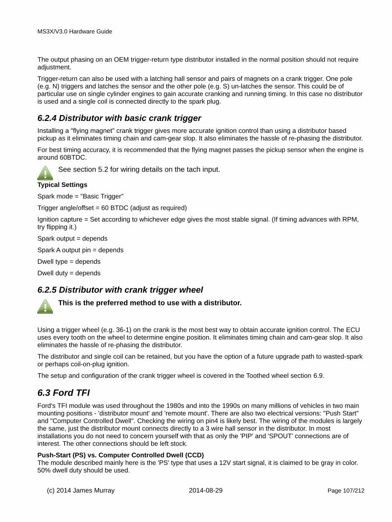
MS3X/V3.0 Hardware Guide
The output phasing on an OEM trigger-return type distributor installed in the normal position should not require adjustment.
Trigger-return can also be used with a latching hall sensor and pairs of magnets on a crank trigger. One pole (e.g. N) triggers and latches the sensor and the other pole (e.g. S) un-latches the sensor. This could be of particular use on single cylinder engines to gain accurate cranking and running timing. In this case no distributoris used and a single coil is connected directly to the spark plug.
6.2.4 Distributor with basic crank triggerInstalling a "flying magnet" crank trigger gives more accurate ignition control than using a distributor based pickup as it eliminates timing chain and cam-gear slop. It also eliminates the hassle of re-phasing the distributor.
For best timing accuracy, it is recommended that the flying magnet passes the pickup sensor when the engine isaround 60BTDC.
See section 5.2 for wiring details on the tach input.
Typical Settings
Spark mode = "Basic Trigger"
Trigger angle/offset = 60 BTDC (adjust as required)
Ignition capture = Set according to whichever edge gives the most stable signal. (If timing advances with RPM, try flipping it.)
Spark output = depends
Spark A output pin = depends
Dwell type = depends
Dwell duty = depends
6.2.5 Distributor with crank trigger wheel
This is the preferred method to use with a distributor.
Using a trigger wheel (e.g. 36-1) on the crank is the most best way to obtain accurate ignition control. The ECU uses every tooth on the wheel to determine engine position. It eliminates timing chain and cam-gear slop. It alsoeliminates the hassle of re-phasing the distributor.
The distributor and single coil can be retained, but you have the option of a future upgrade path to wasted-sparkor perhaps coil-on-plug ignition.
The setup and configuration of the crank trigger wheel is covered in the Toothed wheel section 6.9.
6.3 Ford TFIFord's TFI module was used throughout the 1980s and into the 1990s on many millions of vehicles in two main mounting positions - 'distributor mount' and 'remote mount'. There are also two electrical versions: "Push Start" and "Computer Controlled Dwell". Checking the wiring on pin4 is likely best. The wiring of the modules is largely the same, just the distributor mount connects directly to a 3 wire hall sensor in the distributor. In most installations you do not need to concern yourself with that as only the 'PIP' and 'SPOUT' connections are of interest. The other connections should be left stock.
Push-Start (PS) vs. Computer Controlled Dwell (CCD)The module described mainly here is the 'PS' type that uses a 12V start signal, it is claimed to be gray in color. 50% dwell duty should be used.
(c) 2014 James Murray 2014-08-29 Page 107/212

MS3X/V3.0 Hardware Guide
The 'CCD' type is claimed to be black in color. and pin 4 runs as a diagnostic signal to the original ECU. These modules need standard dwell control e.g. 3ms instead of a fixed duty. Other wiring should be the same.
Base Timing and phasing"Base Timing" on the distributor (with computer control 'SPOUT' disconnected) is around 10BTDC. This is the number you should use as your initial Trigger Offset. As these distributors were designed for ECU control, the rotor arm phasing should already be correct.
Signature PIPNote that there is a TFI variant with "Signature PIP" that in the original install allows for cylinder identification and sequential fuel. This signature is not used in Megasquirt-2.
These distributors should be configured as "Basic Trigger".
Set the mainboard as per section 5.2.4
Typical Settings
Spark mode = "Basic Trigger"
Trigger angle/offset = 10 BTDC as a starting point, fine tune with a timing light.
Ignition capture = "Falling edge"
Spark output = "Going High"
Spark A output pin = "Tacho"
Dwell type = "Fixed duty"
Dwell duty = "50%"
(c) 2014 James Murray 2014-08-29 Page 108/212
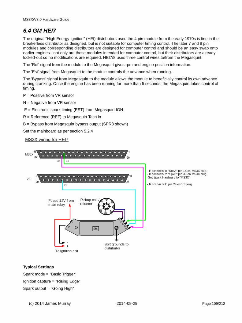
MS3X/V3.0 Hardware Guide
6.4 GM HEI7The original "High Energy Ignition" (HEI) distributors used the 4 pin module from the early 1970s is fine in the breakerless distributor as designed, but is not suitable for computer timing control. The later 7 and 8 pin modules and corresponding distributors are designed for computer control and should be an easy swap onto earlier engines - not only are those modules intended for computer control, but their distributors are already locked-out so no modifications are required. HEI7/8 uses three control wires to/from the Megasquirt.
The 'Ref' signal from the module to the Megasquirt gives rpm and engine position information.
The 'Est' signal from Megasquirt to the module controls the advance when running.
The 'Bypass' signal from Megasquirt to the module allows the module to beneficially control its own advance during cranking. Once the engine has been running for more than 5 seconds, the Megasquirt takes control of timing.
P = Positive from VR sensor
N = Negative from VR sensor
E = Electronic spark timing (EST) from Megasquirt IGN
R = Reference (REF) to Megasquirt Tach in
B = Bypass from Megasquirt bypass output (SPR3 shown)
Set the mainboard as per section 5.2.4
Typical Settings
Spark mode = "Basic Trigger"
Ignition capture = "Rising Edge"
Spark output = "Going High"
(c) 2014 James Murray 2014-08-29 Page 109/212

MS3X/V3.0 Hardware Guide
Spark A output pin = "MS3X spark"
Dwell type = "Standard Dwell"
Nominal Dwell = "3.0"
GM/HEI options = "GM bypass"
6.5 GM HEI8This works the same as HEI7, but the module is packaged differently.
The same board configuration is required as for HEI7 in section 6.4
P = Positive from VR sensor
N = Negative from VR sensor
G = Ground to Megasquirt Sensor ground
B = Bypass from Megasquirt bypass output (SPR3 shown)
R = Reference (REF) to Megasquirt Tach in
E = Electronic spark timing (EST) from Megasquirt IGN
Typical Settings
Spark mode = "Basic Trigger"
Ignition capture = "Rising Edge"
Spark output = "Going High"
(c) 2014 James Murray 2014-08-29 Page 110/212

MS3X/V3.0 Hardware Guide
Spark A output pin = "MS3X spark"
Dwell type = "Standard Dwell"
Nominal Dwell = "3.0"
GM/HEI options = "GM bypass"
6.6 Dual Sync DistributorA dual-sync distributor is an aftermarket locked distributor that provides a clean trigger signal for an ECU. The signal can be used for sequential fuel and spark.
Setting the rotor arm phasing is important as shown in section 6.2.2.
It is possible to use both signals from the dual-sync distributor and control a distributorless ignition system (wasted spark or wasted-COP.) Use the "Dual wheel" option in the Trigger Wheel system. Set the rotor arm phasing, then determine the tooth#1 angle from the Trigger Wheel page.
Alternative: It is possible to ignore the "reference" signal from the distributor and configure as a regular distributor using "Basic Trigger." This will allow batch fire fuel only.
6.7 Ford EDIS
Ford's Electronic Distributorless Ignition System (EDIS) is an ignition system that does not require a cam position signal. It requires a variable reluctor (VR) sensor and a 36-1 tooth crank wheel (36-1 means '36 teeth minus one', and refers to 36 evenly spaced teeth, one of which has been removed), it will not work with other pattern wheels or hall sensors.
EDIS is a particularly easy way to install programmable ignition control on an older engine with a distributor. TheEDIS modules are very reliable and the system works well. The EDIS module itself handles all the decoding of the toothed wheel and sends one pulse per cylinder to the ECU.
It is strongly advised to use Ford VR sensors and Ford coilpacks with the EDIS modules. They were designed towork together and do.
Note! If your engine already has a different supported trigger wheel setup, consider utilizing that before retro-fitting EDIS.
6.7.1 System componentsThe EDIS system is made up of:
• EDIS module,
• crank wheel,
• crank variable reluctor (VR) sensor and
• one or more coil pack(s).
See appendix B for a junk-yard hunters guide to finding EDIS.
(c) 2014 James Murray 2014-08-29 Page 111/212

MS3X/V3.0 Hardware Guide
6.7.2 ECU wiring
Set the mainboard as per section 5.2.4.
Typical Settings
Spark mode = "EDIS"
Ignition capture = "Rising Edge"
Spark output = "Going High"
Spark A output pin = "MS3X spark"
6.7.3 Module wiringThe EDIS system comes in three varieties : EDIS4, EDIS6, EDIS8 which are suited to even-fire 4, 6, 8 cylinder
(c) 2014 James Murray 2014-08-29 Page 112/212
Megasquirt
Spk A
Tachin
EDIS
SAW
PIP
Optional diagnostic jumper
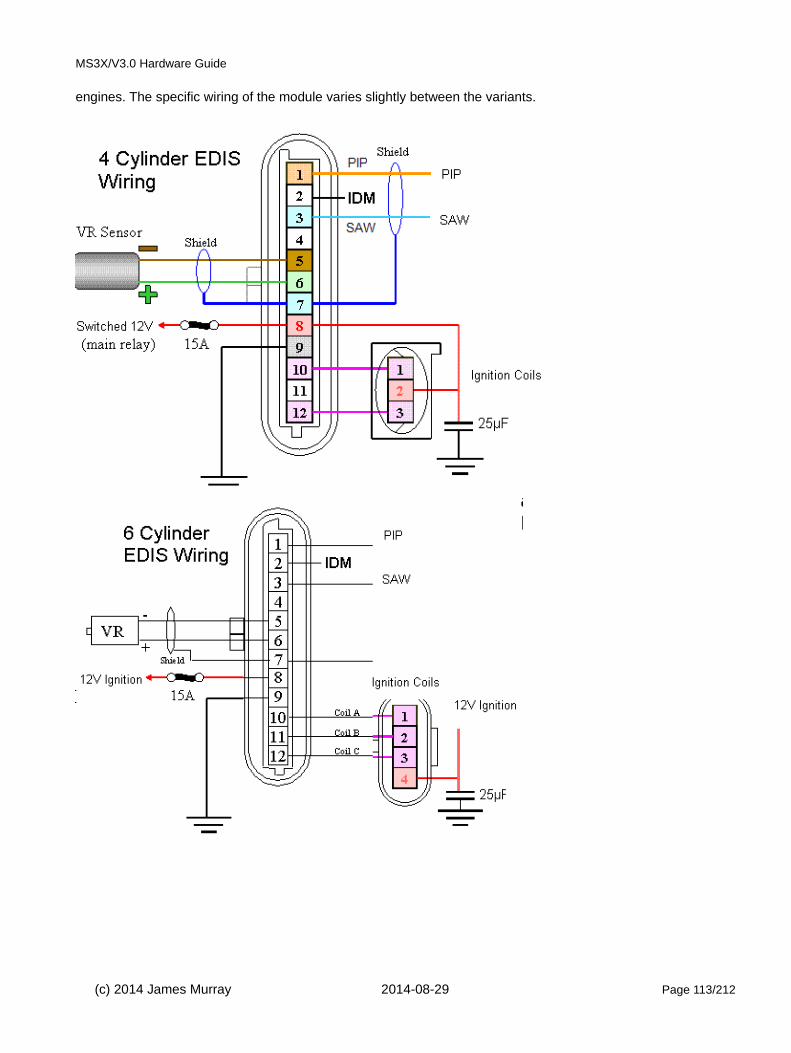
MS3X/V3.0 Hardware Guide
engines. The specific wiring of the module varies slightly between the variants.
(c) 2014 James Murray 2014-08-29 Page 113/212

MS3X/V3.0 Hardware Guide
6.7.4 36-1 trigger wheel and VR sensorThe relationship of the VR sensor and the missing tooth is critical. The EDIS module expects and requires a specific phasing.
On engines originally equipped with EDIS this will already be set. Later Ford engines also maintain the same phasing even though the EDIS function is now built into the ECU.
Note that while the relationship of the VR sensor and the missing tooth is critical, the actual placement of the VRsensor on your engine is not. i.e. the VR sensor could be at 12 o'clock, 3 o'clock, 6 o'clock, 9 o'clock - it really does not matter - so long as the wheel is phased to match.
See the diagrams below EDIS4, EDIS6, EDIS8. The main diagrams show clockwise engine rotation as that is the most common, there is an anti-clockwise example afterwards.
For each module type there are two phasing diagrams shown.
Both methods achieve the same result.
• method a - engine is set to TDC and teeth counted
• method b - engine is set to angle X BTDC and missing tooth aligned with sensor
Use method 'a' if you can. Alternatively, some installers may find method b easier to understand.
6.7.4.1 EDIS4 - Clockwise rotation (normal) - method a
Set your engine at TDC, then put the missing tooth 9 teeth earlier (more clockwise) than the sensor. This will putthe center of a tooth central to the sensor.
(c) 2014 James Murray 2014-08-29 Page 114/212
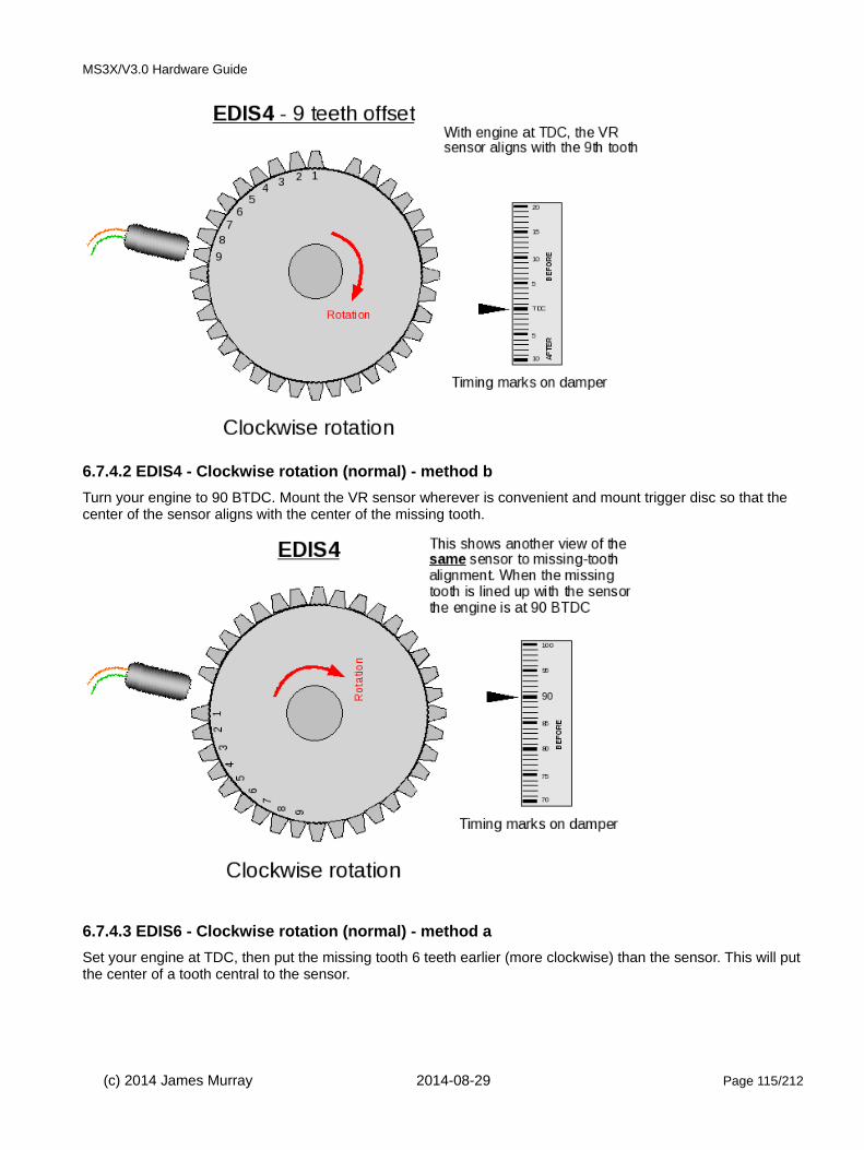
MS3X/V3.0 Hardware Guide
6.7.4.2 EDIS4 - Clockwise rotation (normal) - method b
Turn your engine to 90 BTDC. Mount the VR sensor wherever is convenient and mount trigger disc so that the center of the sensor aligns with the center of the missing tooth.
6.7.4.3 EDIS6 - Clockwise rotation (normal) - method a
Set your engine at TDC, then put the missing tooth 6 teeth earlier (more clockwise) than the sensor. This will putthe center of a tooth central to the sensor.
(c) 2014 James Murray 2014-08-29 Page 115/212

MS3X/V3.0 Hardware Guide
6.7.4.4 EDIS6 - Clockwise rotation (normal) - method b
A different way of looking at the SAME phasing.Turn your engine to 60 BTDC. Mount the VR sensor wherever is convenient and mount trigger disc so that the center of the sensor aligns with the center of the missing tooth.
6.7.4.5 EDIS8 - Clockwise rotation (normal) - method a
Set your engine at TDC, then put the missing tooth 5 teeth earlier (more clockwise) than the sensor. This will putthe center of a tooth central to the sensor.
(c) 2014 James Murray 2014-08-29 Page 116/212

MS3X/V3.0 Hardware Guide
6.7.4.6 EDIS8 - Clockwise rotation (normal) - method b
Turn your engine to 50 BTDC. Mount the VR sensor wherever is convenient and mount trigger disc so that the center of the sensor aligns with the center of the missing tooth.
6.7.4.7 EDIS4 anti-clockwise
Anti-clockwise rotation.The same applies, but directions are reversed.
(c) 2014 James Murray 2014-08-29 Page 117/212

MS3X/V3.0 Hardware Guide
6.7.5 Checking the timingAs with all installs, it is important to confirm the timing is correct. To test this it is best to first run the EDIS in limphome mode. This can be achieved by disconnecting the SAW plug/socket or switching off/unplugging the ECU. Fit your strobe onto no.1 plug lead as normal (you may need to try the other tower of the pair).
A dumb strobe is advised, or use a strobe that is compatible with wasted-spark or 2-stroke.
Ensure EDIS still has power and crank your engine, check that the timing is exactly 10deg. If not, adjust your sensor until it is. It is safe to idle the engine with the SAW lead disconnected, timing should be rock solid at 10BTDC. Don't forget to reconnect the plug when done!
Now that you have confirmed that the EDIS is correctly running at 10BTDC base timing, you need to check that ECU is correctly commanding timing on the EDIS.Start the engine and then on the Ignition settings menu on your tuning computer, select "Fixed Timing" and enter15 BTDC, check that you strobe 15 BTDC on the crank.
When done, return the setting to "Use table" and Burn.
6.7.6 Optional cam sensorMegasquirt-3 supports a cam sensor with EDIS for sequential fuel. A single tooth at cam speed is required, this should pass the sensor before the engine reaches TDC #1 compression.
The cam sensor should be wired following the standard cam sensor instructions in section 5.2.14.
(c) 2014 James Murray 2014-08-29 Page 118/212

MS3X/V3.0 Hardware Guide
6.8 GM DIS (for reference only)As far as the ECU is concerned, GMDIS works similarly to HEI7. Even though the module is controlling wasted spark ignition, the ECU does not receive any cylinder identification or phase information.
The same internal modifications are required as for HEI7 in section 6.4
This wiring need confirming.
P = Positive from VR sensor
N = Negative from VR sensor
G = Ground to Megasquirt Sensor ground
B = Bypass from Megasquirt SPR3
R = Reference (REF) to Megasquirt Tach in.
E = Electronic spark timing (EST) from Megasquirt IGN (36)
These settings need confirming.
Ignition capture = "Falling" (check!)
Spark output = "Going High" (check!)
Spark A output pin = "MS3X spark"
Dwell type = "Standard Dwell"
(c) 2014 James Murray 2014-08-29 Page 119/212
GMDIS General layout
Megasquirt
Spk A
Tach in
Spk B
SensorGND
GMDIS
E
B
G
R
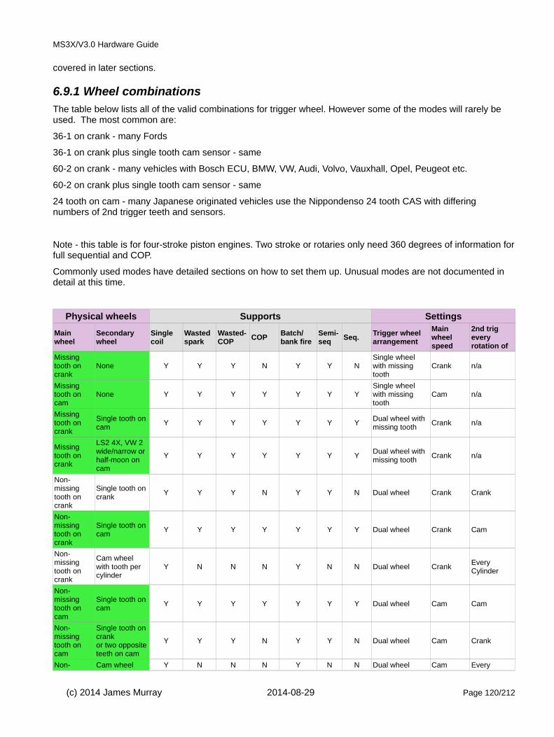
MS3X/V3.0 Hardware Guide
covered in later sections.
6.9.1 Wheel combinationsThe table below lists all of the valid combinations for trigger wheel. However some of the modes will rarely be used. The most common are:
36-1 on crank - many Fords
36-1 on crank plus single tooth cam sensor - same
60-2 on crank - many vehicles with Bosch ECU, BMW, VW, Audi, Volvo, Vauxhall, Opel, Peugeot etc.
60-2 on crank plus single tooth cam sensor - same
24 tooth on cam - many Japanese originated vehicles use the Nippondenso 24 tooth CAS with differing numbers of 2nd trigger teeth and sensors.
Note - this table is for four-stroke piston engines. Two stroke or rotaries only need 360 degrees of information forfull sequential and COP.
Commonly used modes have detailed sections on how to set them up. Unusual modes are not documented in detail at this time.
Physical wheels Supports Settings
Main wheel
Secondary wheel
Single coil
Wasted spark
Wasted-COP
COPBatch/bank fire
Semi-seq
Seq.Trigger wheel arrangement
Main wheel speed
2nd trig every rotation of
Missing tooth on crank
None Y Y Y N Y Y NSingle wheel with missing tooth
Crank n/a
Missing tooth on cam
None Y Y Y Y Y Y YSingle wheel with missing tooth
Cam n/a
Missing tooth on crank
Single tooth on cam
Y Y Y Y Y Y YDual wheel with missing tooth
Crank n/a
Missing tooth on crank
LS2 4X, VW 2 wide/narrow or half-moon on cam
Y Y Y Y Y Y YDual wheel with missing tooth
Crank n/a
Non-missing tooth on crank
Single tooth on crank
Y Y Y N Y Y N Dual wheel Crank Crank
Non-missing tooth on crank
Single tooth on cam
Y Y Y Y Y Y Y Dual wheel Crank Cam
Non-missing tooth on crank
Cam wheel with tooth per cylinder
Y N N N Y N N Dual wheel CrankEvery Cylinder
Non-missing tooth on cam
Single tooth on cam
Y Y Y Y Y Y Y Dual wheel Cam Cam
Non-missing tooth on cam
Single tooth on crankor two oppositeteeth on cam
Y Y Y N Y Y N Dual wheel Cam Crank
Non- Cam wheel Y N N N Y N N Dual wheel Cam Every
(c) 2014 James Murray 2014-08-29 Page 120/212
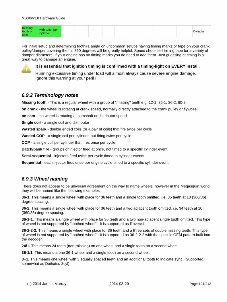
MS3X/V3.0 Hardware Guide
missing tooth on cam
with tooth per cylinder
Cylinder
For initial setup and determining tooth#1 angle on uncommon setups having timing marks or tape on your crank pulley/damper covering the full 360 degrees will be greatly helpful. Speed shops sell timing tape for a variety of damper diameters. If your engine has no timing marks you do need to add them. Just guessing at timing is a great way to damage an engine.
It is essential that ignition timing is confirmed with a timing-light on EVERY install.
Running excessive timing under load will almost always cause severe engine damage. Ignore this warning at your peril !
6.9.2 Terminology notes Missing tooth - This is a regular wheel with a group of "missing" teeth e.g. 12-1, 36-1, 36-2, 60-2
on crank - the wheel is rotating at crank speed, normally directly attached to the crank pulley or flywheel
on cam - the wheel is rotating at camshaft or distributor speed
Single coil - a single coil and distributor
Wasted spark - double ended coils (or a pair of coils) that fire twice per cycle
Wasted-COP - a single coil per cylinder, but firing twice per cycle
COP - a single coil per cylinder that fires once per cycle
Batch/bank fire - groups of injector fired at once, not timed to a specific cylinder event
Semi-sequential - injectors fired twice per cycle timed to cylinder events
Sequential - each injector fires once per engine cycle timed to a specific cylinder event
6.9.3 Wheel naming There does not appear to be universal agreement on the way to name wheels, however in the Megasquirt world,they will be named like the following examples.
36-1. This means a single wheel with place for 36 teeth and a single tooth omitted. i.e. 35 teeth at 10 (360/36) degree spacing.
36-2. This means a single wheel with place for 36 teeth and a two adjacent tooth omitted. i.e. 34 teeth at 10 (360/36) degree spacing.
36-1-1. This means a single wheel with place for 36 teeth and a two non-adjacent single tooth omitted. This typeof wheel is not supported by "toothed wheel" - it is supported as Rover#1
36-2-2-2. This means a single wheel with place for 36 teeth and a three sets of double missing teeth. This type of wheel is not supported by "toothed wheel" - it is supported as 36-2-2-2 with the specific OEM pattern built intothe decoder.
24/1. This means 24 teeth (non-missing) on one wheel and a single tooth on a second wheel.
36-1/1. This means a one 36-1 wheel and a single tooth on a second wheel.
3+1. This means one wheel with 3 equally spaced teeth and an additional tooth to indicate sync. (Supported somewhat as Daihatsu 3cyl)
(c) 2014 James Murray 2014-08-29 Page 121/212

MS3X/V3.0 Hardware Guide
Spark Mode - set to "Toothed Wheel"
Trigger Angle/Offset - always zero
Angle between main and return - n/a
Oddfire small angle - for oddfire engines this specifies the smallest of the crank angles between ignition events
GM HEI/DIS options - n/a
420A/NGC alternate cam - n/a
Use cam signal if available - n/a
Oddfire phasing - usually "Alternate" but for Vmax use "Paired"
Skip pulses - number of input pulses at startup that are ignored before decoding begins. Safe to leave at 3.
Ignition Input Capture - see ignition page
Spark output - see ignition page
Number of coils - see ignition page
Spark hardware in use - see ignition page
Cam input - see ignition page
Trigger wheel arrangement - see table above for correct settings
Trigger wheel teeth - the number of effective teeth, counting the missing teeth as if they existed. i.e. a 36-1 wheel has 35 physical teeth, but enter 36.
Missing Teeth - the number of missing teeth. Common are 1 for 36-1, or 2 for 60-2 or 36-2
Tooth #1 angle - definition depends on whether main wheel is missing or non-missing type. See sections below.
Main wheel speed - Does the main wheel rotate at crankshaft speed or camshaft (distributor) speed.
Second trigger active on - Like ignition input capture above, specifies which voltage level is considered "active"
Level for phase 1 - only applies in "Poll level" mode. See Dual+Missing section.
and every rotation of - how often are second trigger input pulses received. See Dual Wheel section
All of the settings on the right hand side of the page are general and will be covered in the Ignition manual.
There are two main categories of install - Retrofit and Existing.
6.9.4 Retrofit installIf you have an engine that did not originally come equipped with a trigger wheel (e.g. a distributor based, pre-EFI engine) then you have to mount a wheel and sensor and set the phasing correctly.
Suggestion for a typical car engine
Install a 36-1 wheel on the crank for accurate wasted spark ignition and batch-fire fuel.
For installs requiring COP or sequential fuel, install a 36-1 wheel on the crank and a 50/50 cam tooth with gear-tooth hall sensor.
60-2 works great on most engines too.
For very high revving engines (such as motorcycle engines) due to the number of teeth per second, 36-1, 24-1 or 12-1 are preferred. (Megasquirt-3 can reliably support higher revs and more teeth than Megasquirt-2.)
(c) 2014 James Murray 2014-08-29 Page 122/212

MS3X/V3.0 Hardware Guide
While the code can cope with any sensor/tooth phasing, during cranking the rpms vary up and down greatly as the engine rotates. It is desirable to place the missing tooth such that it passes the sensor when the engine speed is somewhat stable or it may be impossible for the ECU to "see" the missing tooth. The OEMs have foundthat certain tooth#1 angles work well and it is worth following their lead.
It is suggested to align your wheel and sensor to arrive at the following tooth #1 angles.
4 cylinders ~90-120 deg
6 cylinders ~50 deg
8 cylinders ~40 deg
Take a look at Appendix B pages for places to source used trigger wheels, sensors and coilpacks. Note that you do NOT need the EDIS module, so later ('internal-EDIS') cars are useful donors too.
Mounting the wheel is quite critical in that it MUST be mounted so it rotates without moving up, down, left or right as the sensor needs to see all of the teeth with a gap of 0.75 - 1.0mm.
Having mounted the wheel and sensor, you can proceed for an existing install.
6.9.5 Existing installIn this case where you are fitting Megasquirt to an engine already fitted with a trigger wheel, your main task is towire up the sensor(s), determine the tooth #1 angle and wire up your coil(s). It should not normally be necessaryto modify the trigger wheels.
6.9.6 Missing tooth crank wheelThis is a very common configuration for wasted spark with the most typical wheels being 36-1 (Ford) and 60-2 (Bosch.) Note that the missing teeth are in a single group - if your wheel has multiple groups then you need a special wheel decoder. Many custom decoders already exist e.g. 36-2-2-2 and the one matching your wheel must be used instead of this generic "toothed wheel" mode.
The software benefits from a reasonable number of teeth (hence 36 or 60) for best ignition timing accuracy. Lowtooth count wheels such as 4-1 are not advised.
6.9.6.1 What is Tooth #1
With the engine rotating in the normal direction...
Tooth #1 is the first tooth to pass the sensor after the missing tooth gap.
(c) 2014 James Murray 2014-08-29 Page 123/212

MS3X/V3.0 Hardware Guide
We use the term "tooth#1" as it is consistent across wheels with one, two, three or four missing teeth in the group.
Once the software knows the tooth#1 angle it automatically calculates other needed information internally.
The following table shows examples, in this case the tooth#1 angle happens to be 80 degrees.
Clockwise rotation (normal) - method aSet your engine at TDC, then count the number of GAPS to tooth#1 in the direction of rotation (clockwise here) and multiply by the angular size of the tooth. e.g. 8 teeth * 10 deg/tooth = 80 deg
36-1 wheels are 10 deg per tooth 60-2 wheels are 6 deg per tooth24-2 wheels are 15 deg per tooth
Clockwise rotation (normal) - method bA different way of looking at the SAME phasing.Turn your engine so that tooth #1 aligns with the sensor.
Read off the tooth#1 angle from timing marks/tape on the crank pulley.
Typical settings:
Spark mode = Toothed wheel
Trigger angle/offset = 0 (not used in toothed wheel mode)
(c) 2014 James Murray 2014-08-29 Page 124/212

MS3X/V3.0 Hardware Guide
Trigger wheel arrangement = Single wheel with missing tooth
Trigger wheel teeth = number of teeth including missing teeth (e.g. 36, 60 etc.)
Missing teeth = number of missing teeth (e.g. 1, 2)
Tooth #1 angle = tooth #1 angle as determined above
Main wheel speed = Crank wheel
Common combinations:
Ford 4 cyl = 36-1, 80deg tooth #1
Ford 6 cyl = 36-1, 50deg tooth #1
Ford 8 cyl = 36-1, 40deg tooth #1
Bosch 4 cyl (Peugeot, Vauxhall) = 60-2, 114 deg tooth #1
6.9.7 Missing tooth cam wheelThis arrangement is not commonly used by OEMs but does support full sequential with a single wheel and sensor. Cam triggering is less accurate than crank triggering due to timing belt or chain stretch.
The software benefits from a reasonable number of teeth (hence 36 or 60) for best ignition timing accuracy. Lowtooth count wheels such as 8-1 are not advised.
The previous section on missing tooth crank wheel generally applies when the wheel is mounted to the cam, butremember that one rotation of the cam is 720 crank degrees. The settings are in crank degrees. So a tooth#1 that is 8 gaps earlier than the sensor on a 36-1 wheel would give a 160deg tooth#1 angle (8 * 10 * 2 [for cam] )
Typical settings:
Spark mode = Toothed wheel
Trigger angle/offset = 0 (not used in toothed wheel mode)
Trigger wheel arrangement = Single wheel with missing tooth
Trigger wheel teeth = number of teeth including missing teeth (e.g. 36, 60 etc.)
Missing teeth = number of missing teeth (e.g. 1, 2)
Tooth #1 angle = tooth #1 angle as determined above
Main wheel speed = Cam wheel
6.9.8 Missing tooth crank wheel and single tooth cam wheelThis is a very common arrangement that supports full sequential and coil on plug.
(For 50/50 half-moon or 4-window wide/narrow or other polled cam wheels see section 6.9.9)
(c) 2014 James Murray 2014-08-29 Page 125/212

MS3X/V3.0 Hardware Guide
The definition of tooth#1 is the same as the basic missing tooth crank wheel and should be phased in the same way. Ensure you also read the section above. The cam input tells the code which engine cycle/phase it is on. From the crank wheel alone the code knows when cylinder one is at TDC, but it cannot distinguish TDC compression or TDC exhaust. The cam sensor adds this information which is why it needs to be one pulse only per engine cycle.
The cam signal is a single pulse usually generated by a narrow tooth, vane or window. During setup, you will need to use the composite logger in TunerStudio to verify the phasing between the crank and cam signals is acceptable.
To confirm correct cam sensor phasing proceed as follows. (Note that some engines should not be rotated backwards, use tape or pen marks on the pulleys or sprockets to remember positions and rotate forwards only.)
(c) 2014 James Murray 2014-08-29 Page 126/212
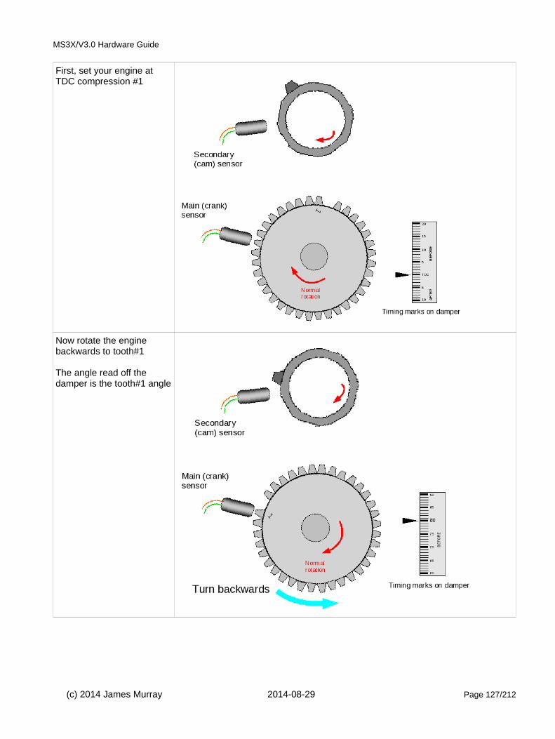
MS3X/V3.0 Hardware Guide
First, set your engine at TDC compression #1
Now rotate the engine backwards to tooth#1
The angle read off the damper is the tooth#1 angle
(c) 2014 James Murray 2014-08-29 Page 127/212

MS3X/V3.0 Hardware Guide
Now rotate the engine backwards some more - this is the best place for the cam tooth to pass the sensor.
Typical settings:
Spark mode = Toothed wheel
Trigger angle/offset = 0 (not used in toothed wheel mode)
Trigger wheel arrangement = Dual wheel with missing tooth
Trigger wheel teeth = number of teeth including missing teeth (e.g. 36, 60 etc.)
Missing teeth = number of missing teeth (e.g. 1, 2)
Tooth #1 angle = tooth #1 angle as determined above
Main wheel speed = Crank wheel
Second trigger active on = Rising edge (confirm with composite logger)
6.9.9 Missing tooth crank wheel and polled cam wheelThis is a fairly common arrangement that supports full sequential and coil on plug. Here a missing tooth wheel isused on the crank in the common way and a hall-effect or gear-tooth sensor is used on the cam with a long tooth or window or vane. This gives you the ability to have full sequential, but the engine syncs up as fast as a regular missing tooth crank wheel.
Different OEM implementations exist - some engines use a 50/50 cam pattern, Vauxhall red-top engines use a window in the distributor rotor that spans the missing tooth region. Many newer engines with Bosch ECUs utilizea 4 tooth wide/narrow cam trigger, this is used on some VW, GM LS2, LS4 and some Mercedes. As far as the code is concerned these are equivalent because it only 'looks at' (polls) the cam just after the missing tooth to determine engine phase.
The wide/narrow type is used for VVT control on some engines and is supported by Megasquirt-3.
(c) 2014 James Murray 2014-08-29 Page 128/212

MS3X/V3.0 Hardware Guide
Typical polled cam triggers:
4 tooth wide/narrow type
e.g. GM LS2 4X / VW / Mercedes
Vane cup with single window
e.g. 1 window Bosch dizzy in Vauxhall red-top.
Half-moon type
(c) 2014 James Murray 2014-08-29 Page 129/212
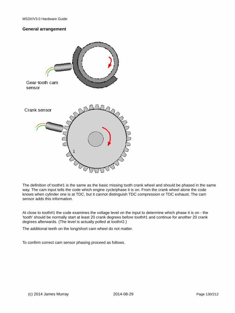
MS3X/V3.0 Hardware Guide
General arrangement
The definition of tooth#1 is the same as the basic missing tooth crank wheel and should be phased in the same way. The cam input tells the code which engine cycle/phase it is on. From the crank wheel alone the code knows when cylinder one is at TDC, but it cannot distinguish TDC compression or TDC exhaust. The cam sensor adds this information.
At close to tooth#1 the code examines the voltage level on the input to determine which phase it is on - the 'tooth' should be normally start at least 20 crank degrees before tooth#1 and continue for another 20 crank degrees afterwards. (The level is actually polled at tooth#2.)
The additional teeth on the long/short cam wheel do not matter.
To confirm correct cam sensor phasing proceed as follows.
(c) 2014 James Murray 2014-08-29 Page 130/212
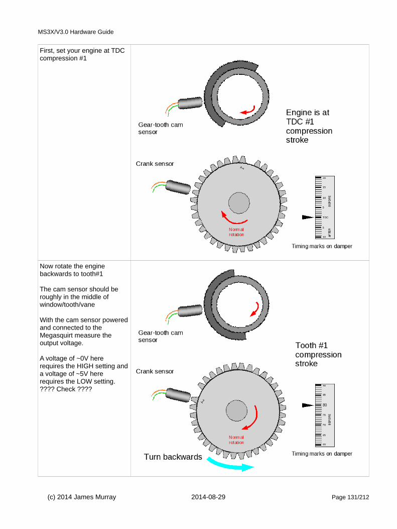
MS3X/V3.0 Hardware Guide
First, set your engine at TDC compression #1
Now rotate the engine backwards to tooth#1
The cam sensor should be roughly in the middle of window/tooth/vane
With the cam sensor poweredand connected to the Megasquirt measure the output voltage.
A voltage of ~0V here requires the HIGH setting anda voltage of ~5V here requires the LOW setting.???? Check ????
(c) 2014 James Murray 2014-08-29 Page 131/212

MS3X/V3.0 Hardware Guide
Now rotate the engine backwards a full revolution.
The cam sensor will be opposite that previous window/tooth/vane. (If there was a window before it must be a vane now and vice-versa.)
Typical settings:
Spark mode = Toothed wheel
Trigger angle/offset = 0 (not used in toothed wheel mode)
Trigger wheel arrangement = Dual wheel with missing tooth
Trigger wheel teeth = number of teeth including missing teeth (e.g. 36, 60 etc.)
Missing teeth = number of missing teeth (e.g. 1, 2)
Tooth #1 angle = tooth #1 angle as determined above
Main wheel speed = Crank wheel
Second trigger active on = Poll level
Level for phase one = as determined above
6.9.10 Nippondenso CASThe Nippondenso CAS (crank angle sensor) comes in a number of versions which all use a 24 tooth main wheeland a second wheel with one, two, three or four teeth. There is a single sensor (called Ne) pointing at the 24 tooth wheel and one (G1) or two (G1 and G2) sensors pointing at the second wheel.
This style of CAS is very common on Toyota and Mazda engine from the 1980s and 1990s.
The number of teeth on the second wheel determines whether it can be used (without modification) for single coil distributor, wasted spark or coil-on-plug (COP) and sequential.
The version with a single tooth and two pickup sensors is intended for sequential. The two sensors are used by the OEM to allow the engine to synchronize within one engine revolution. Presently we only support using one of the 'G' sensors.
(c) 2014 James Murray 2014-08-29 Page 132/212
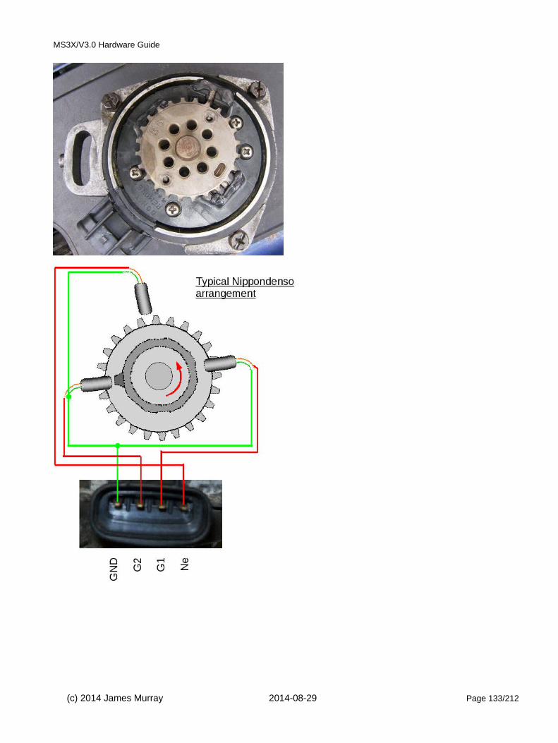
MS3X/V3.0 Hardware Guide
(c) 2014 James Murray 2014-08-29 Page 133/212
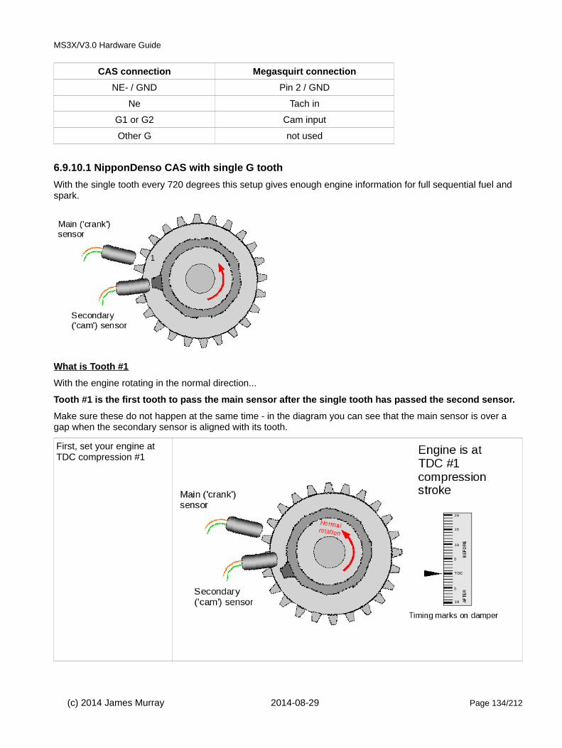
MS3X/V3.0 Hardware Guide
CAS connection Megasquirt connection
NE- / GND Pin 2 / GND
Ne Tach in
G1 or G2 Cam input
Other G not used
6.9.10.1 NipponDenso CAS with single G tooth
With the single tooth every 720 degrees this setup gives enough engine information for full sequential fuel and spark.
What is Tooth #1
With the engine rotating in the normal direction...
Tooth #1 is the first tooth to pass the main sensor after the single tooth has passed the second sensor.
Make sure these do not happen at the same time - in the diagram you can see that the main sensor is over a gap when the secondary sensor is aligned with its tooth.
First, set your engine at TDC compression #1
(c) 2014 James Murray 2014-08-29 Page 134/212

MS3X/V3.0 Hardware Guide
Now rotate the engine backwards until the 'cam' sensor and tooth line up.If you rotated more than one turn, then add 360 to your tooth#1 angle.
Now rotate the engine forwards until the next 'crank' tooth aligns with its sensor.The crank angle now is thetooth#1 angle.(Note that angles shown indiagram are examples only)
Typical settings:
Spark mode = Toothed wheel
Trigger angle/offset = 0 (not used in toothed wheel mode)
Trigger wheel arrangement = Dual wheel
Trigger wheel teeth = number of teeth
Tooth #1 angle = tooth #1 angle as determined above
Main wheel speed = Cam wheel
Second trigger active on = Rising (verify with composite logger)
and every rotation of = Cam
(c) 2014 James Murray 2014-08-29 Page 135/212

MS3X/V3.0 Hardware Guide
6.9.10.2 NipponDenso CAS with two G teeth
With the cam tooth every 360 degrees this setup gives enough engine information for semi-sequential fuel and wasted spark. (On a rotary such as the RX7, or a two-stroke engine, full sequential fuel and spark is possible as the engine cycle spans 360 degrees.)
What is Tooth #1
With the engine rotating in the normal direction...
Tooth #1 is the first tooth to pass the main sensor after either cam tooth has passed the second sensor.
Make sure these do not happen at the same time - in the diagram you can see that the main sensor is over a gap when the secondary sensor is aligned with its tooth.
Use the instructions in the previous single cam tooth section to determine your tooth#1 angle. It will always be between 0 and 360 degrees.
Typical settings:
Spark mode = Toothed wheel
Trigger angle/offset = 0 (not used in toothed wheel mode)
Trigger wheel arrangement = Dual wheel
Trigger wheel teeth = number of teeth
Tooth #1 angle = tooth #1 angle as determined above
Main wheel speed = Cam wheel
Second trigger active on = Rising (verify with composite logger)
and every rotation of = Crank
(c) 2014 James Murray 2014-08-29 Page 136/212

MS3X/V3.0 Hardware Guide
6.9.10.3 NipponDenso CAS with three or four G teeth
This version is used on three and four cylinder engines with one G tooth per cylinder.
There is only enough position information to run a distributor and untimed injection.
It is not strictly necessary to use both Ne and G wheels. Using both will give you the improved timing accuracy from the 'every-tooth' wheel decoder system, but for simpler installs it is possible to use the 'G' input only and configure as "Basic Trigger" instead. Timing will not be as accurate though.
What is Tooth #1
With the engine rotating in the normal direction...
Tooth #1 is the first tooth to pass the main sensor after either cam tooth has passed the second sensor.
Make sure these do not happen at the same time - in the diagram you can see that the main sensor is over a gap when the secondary sensor is aligned with its tooth.
Use the instructions in the previous single cam tooth section to determine your tooth#1 angle. It will always be between 0 and 360 degrees.
Typical settings:
Spark mode = Toothed wheel
Trigger angle/offset = 0 (not used in toothed wheel mode)
Trigger wheel arrangement = Dual wheel
Trigger wheel teeth = number of teeth
Tooth #1 angle = tooth #1 angle as determined above
Main wheel speed = Cam wheel
Second trigger active on = Rising (verify with composite logger)
and every rotation of = Every cylinder
6.9.11 Non-missing tooth crank wheel with one cam toothThis arrangement is not commonly used by OEMs but could be used to extend a simple 'distributor' crank trigger
(c) 2014 James Murray 2014-08-29 Page 137/212

MS3X/V3.0 Hardware Guide
to support sequential. It can also be useful on bike engines with very uneven cranking RPMs that struggle to detect the gap in a missing tooth wheel.
Generally Megasquirt benefits from many crank teeth to improve ignition timing accuracy. However, with this wheel arrangement, you need to beware of trying to use too many teeth on the crank as there is a risk of the trigger inputs overlapping as the cam belt or chain stretches. If this overlap occurs, it will cause sync-loss as the cam tooth moves from being seen "before" to "after" a crank tooth or vice-versa.
12 crank teeth is the suggested maximum.
What is Tooth #1
With the engine rotating in the normal direction...
Tooth #1 is the first tooth to pass the main sensor after the cam tooth has passed the second sensor.
Make sure these do not happen at the same time - in the diagrams below you can see that the main sensor is over a gap when the secondary sensor is aligned with its tooth.
(c) 2014 James Murray 2014-08-29 Page 138/212

MS3X/V3.0 Hardware Guide
First, set your engine at TDC compression#1
Now rotate the engine backwards until thecam sensor and tooth line up.If you rotated more than one turn, then add 360 to your tooth#1 angle.
(c) 2014 James Murray 2014-08-29 Page 139/212

MS3X/V3.0 Hardware Guide
Now rotate the engine forwards until the next crank tooth aligns with its sensor.The crank angle now is the tooth#1 angle.(Note that angles shown in diagram are examples only)
Typical settings:
Spark mode = Toothed wheel
Trigger angle/offset = 0 (not used in toothed wheel mode)
Trigger wheel arrangement = Dual wheel
Trigger wheel teeth = number of teeth
Tooth #1 angle = tooth #1 angle as determined above
Main wheel speed = Cam wheel
Second trigger active on = Rising (verify with composite logger)
and every rotation of = Cam
6.9.12 Mitsubishi CAS with aftermarket disc - single coil / wasted spark
This replacement trigger disc is equivalent to a 12-1 wheel at crank speed with a single pulse on the cam.
The inner signal alone is good enough to run a single coil or distributor.
The addition of the outer single slot signal allows for coil-on-plug or sequential fuel.
Other variants exist.
For single-coil or wasted spark, only the inner track is required.
(c) 2014 James Murray 2014-08-29 Page 140/212
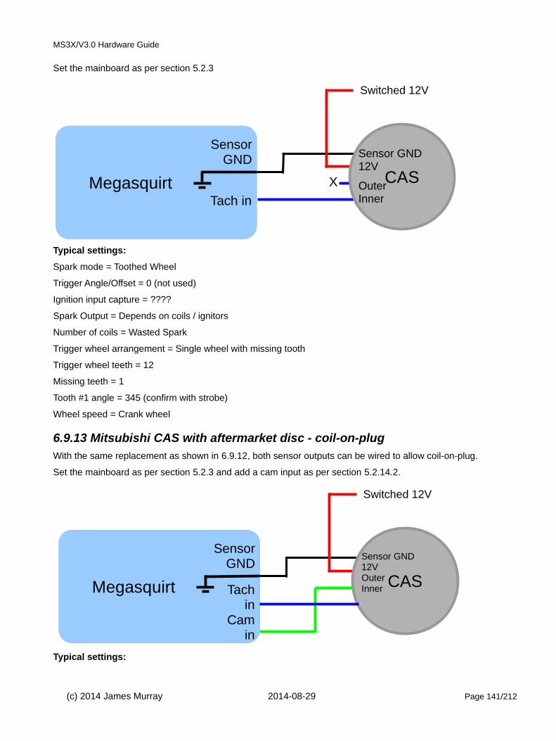
MS3X/V3.0 Hardware Guide
Set the mainboard as per section 5.2.3
Typical settings:
Spark mode = Toothed Wheel
Trigger Angle/Offset = 0 (not used)
Ignition input capture = ????
Spark Output = Depends on coils / ignitors
Number of coils = Wasted Spark
Trigger wheel arrangement = Single wheel with missing tooth
Trigger wheel teeth = 12
Missing teeth = 1
Tooth #1 angle = 345 (confirm with strobe)
Wheel speed = Crank wheel
6.9.13 Mitsubishi CAS with aftermarket disc - coil-on-plugWith the same replacement as shown in 6.9.12, both sensor outputs can be wired to allow coil-on-plug.
Set the mainboard as per section 5.2.3 and add a cam input as per section 5.2.14.2.
Typical settings:
(c) 2014 James Murray 2014-08-29 Page 141/212
Megasquirt
SensorGND
Tach in
CAS
Sensor GND12V
OuterInner
Switched 12V
X
Megasquirt
SensorGND
CAS
Sensor GND12VOuterInner
Switched 12V
Tachin
Cam in

MS3X/V3.0 Hardware Guide
Spark mode = Toothed Wheel
Trigger Angle/Offset = 0 (not used)
Ignition input capture = ????
Spark Output = Depends on coils / ignitors
Number of coils = Coil on plug
Trigger wheel arrangement = Dual wheel with missing tooth
Trigger wheel teeth = 12
Missing teeth = 1
Tooth #1 angle = 345 (confirm with strobe)
Wheel speed = Crank wheel
Second trigger active on = poll level
Level for phase 1 = ???
6.9.14 Other wheel arrangementsThe examples shown here are not an exhaustive list of all the combinations that are possible, for other arrangements of crank and cam wheels you will need to apply the general principles to your install.
6.9.15 Example: Ford ZetecThe Ford Zetec is a popular four-cylinder four-stroke used on many Fords from the mid nineties onwards. As standard these engines use a 36-1 crank wheel and a VR sensor. Set the mainboard as per section 5.2.2.
A high-current coilpack is used and requires an external 2 channel ignitor.
Megasquirt-3 only needs the crank signal to run wasted-spark and batch fire fuel, this is the simplest configuration.
(Connecting and configuring the cam signal would allow sequential fuel and coil-on-plug ignition with suitable coils.)
Alternative #1: Customise the mainboard for two high current outputs - see the MS3base/V3.0 manual.
Alternative #2: use a logic wasted spark coil pack such as the VW item (032 905 106B) shown in section: 5.3.2 instead of the stock coilpack.
Typical settings:
Spark mode = Toothed Wheel
Trigger Angle/Offset = 0 (not used)
Ignition input capture = Rising (confirm with tooth logger)
Spark Output = Going High
Number of coils = Wasted Spark
Trigger wheel arrangement = Single wheel with missing tooth
Trigger wheel teeth = 36
Missing teeth = 1
Tooth #1 angle = 90 (tweak with strobe)
(c) 2014 James Murray 2014-08-29 Page 142/212

MS3X/V3.0 Hardware Guide
Wheel speed = Crank wheel
6.10 Neon/420AThe "Neon/420A" mode supports the following vehicles when equipped with a 2.0 or 2.4 4-cylinder Chrysler engine. Also known as "1st gen Neon".
"NS" body models:
1996-2000 Chrysler Town and Country
1996-2000 Dodge Caravan/Grand Caravan
1996-2000 Plymouth Voyager/Grand Voyager
"JA" body models:
1995-02 Chrysler Cirrus
1995-02 Dodge Stratus
1996-2000 Plymouth Breeze
"JX" body models:
1996-02 Chrysler Sebring Convertible
"PL" body models:
1995-02 Dodge Neon
1995-2001 Plymouth Neon
"PT" body models:
01-02 Chrysler PT Cruiser
"FJ" body models:
1995-02 Chrysler Sebring Coupe
1995-2000 Dodge Avenger
The crank and cam signal pattern looks as follows:
Megasquirt-3 only needs the crank signal to run wasted-spark and batch fire fuel, this is the simplest configuration.
(Connecting and configuring the cam signal would allow sequential fuel and coil-on-plug ignition with suitable coils.)
(c) 2014 James Murray 2014-08-29 Page 143/212

MS3X/V3.0 Hardware Guide
The following diagram shows the recommended wiring using an external ignitor to drive the standard 420A high-current coilpack.
Alternative #1: Use an a different ignitor such as the Quadspark.
Alternative #1: Customise the mainboard for high current outputs - see the MS3base/V3.0 Hardware manual.
Alternative #2: use a logic wasted spark coil pack such as the VW item (032 905 106B) shown in section: 5.3.2 instead of the stock coilpack.
(c) 2014 James Murray 2014-08-29 Page 144/212

MS3X/V3.0 Hardware Guide
Typical settings:
Spark mode = 420A
Trigger Angle/Offset = 0 (tweak if required)
Ignition input capture = Rising edge
Spark Output = Going High
Number of coils = Wasted Spark
Injectors are wired up using the general diagrams in section 4.10.2
6.11 36-2+2 (NGC)This ignition mode supports Chrysler's "next gen crank" pattern which was an attempt to consolidate the multitude of crank and cam patterns in use across Chrysler engines. It consists of 36 evenly space slots in a crank wheel, with a -1 (or -2) and +1 (or +2) pattern. The cam patterns vary across 4, 6, 8 cylinder variants.
NGC patterns came into use around 2002.
Megasquirt-3 only needs the crank signal to run wasted-spark and batch fire fuel, this is the simplest configuration. Set the mainboard as per section 5.2.3.
Four cylinder example, wired up the same as 420A in section 6.10
Typical settings:
Spark mode = 36-2+2
Trigger Angle/Offset = 0 (tweak if required)
Ignition input capture = Rising Edge
Spark Output = Going High
Number of coils = Wasted Spark
(c) 2014 James Murray 2014-08-29 Page 145/212

MS3X/V3.0 Hardware Guide
Six and eight cylinder variants are wired up similarly, following the general ignitor and coil wiring diagrams in section 5.3.
6.12 36-2-2-2The 36-2-2-2 mode is designed for use with 4-cyl Subarus and Mazda RX8 engines with stock trigger wheels and sensor positions. (Firmware 1.4.x supports 6-cyl Subaru also.)
As standard, these engines use VR type crank sensors.
See the generic instructions in section 5.2.
Mazda RX8 engines
RX8 engines use rotary specific coils - see section 5.3.6 for wiring.
Typical settings:
Spark mode = 36-2-2-2
Trigger Angle/Offset = 0 (tweak if required)
Ignition input capture = Falling Edge (typically)
Spark Output = Going High
Number of coils = Coil on Plug
Subaru 4cyl engines
Typically, the cam sensor is not used and "wasted spark" or "wasted COP" should be used. An external ignitor will be required to drive the high current coil.
Typical settings:
Spark mode = 36-2-2-2
Trigger Angle/Offset = 0 (tweak if required)
Ignition input capture = Falling Edge (typically)
Spark Output = Going High
Number of coils = Wasted Spark
6.13 Miata 99-05The 99-05 Miata uses a low resolution crank trigger for primary timing and teeth on camshaft to detect phase. Both crank and cam inputs need to be connected.
See the generic instructions in section 5.2.
Most engines of this era run coil-on-plug ignition using logic coils.
See the generic instructions in section 5.3.2 for wiring four logic coils.
Improved timing accuracy can be obtained by upgrading to a regular toothed wheel on the crank shaft, such as the Flyin-Miata 36-2 wheel. (See also section 6.37)
Typical settings:
Spark mode = Miata 99-05
Trigger angle/offset = 0 (adjust with strobe)
(c) 2014 James Murray 2014-08-29 Page 146/212

MS3X/V3.0 Hardware Guide
Ignition input capture = Set according to whichever edge gives the most stable signal. (If timing advances with RPM, try flipping it.)
Spark output = Going High
Number of coils = Wasted Spark
6.14 Subaru 6/7This mode is designed for the EJ series engines with the unique "6/7" trigger - there are six unevenly spaced teeth on the crank wheel and seven teeth in total on the cam sprocket for cylinder identification. Both crank and cam inputs need to be connected..
VR sensors are used which can be directly connected, although some experimentation may be required with resistor "shunts" as the signals have been troublesome for some.
See the generic instructions in section 5.2.
Some/most engines use a wasted spark coil pack. These are believed to be high current and will require an external ignitor.
Typical settings:
Spark mode = Subaru 6/7
Trigger angle/offset = 0 (adjust with strobe)
Ignition input capture = Set according to whichever edge gives the most stable signal. (If timing advances with RPM, try flipping it.)
Spark output = Going High
Number of coils = Wasted Spark
6.15 6G72Known applications include:
• Mitsubishi 3000GT
• Mitsubishi Galant V6
• Some other Mitsubishi and Chrysler V6 models
1991-1992 6G72 use an optical CAS.
Electrically, the two signals on these CAS are connected the same as two hall sensors.
See sections 5.2.3 and 5.2.14.2 for mainboard modifications.
The outer track is considered to be the 'crank' signal and the inner track is the 'cam'.
(c) 2014 James Murray 2014-08-29 Page 147/212
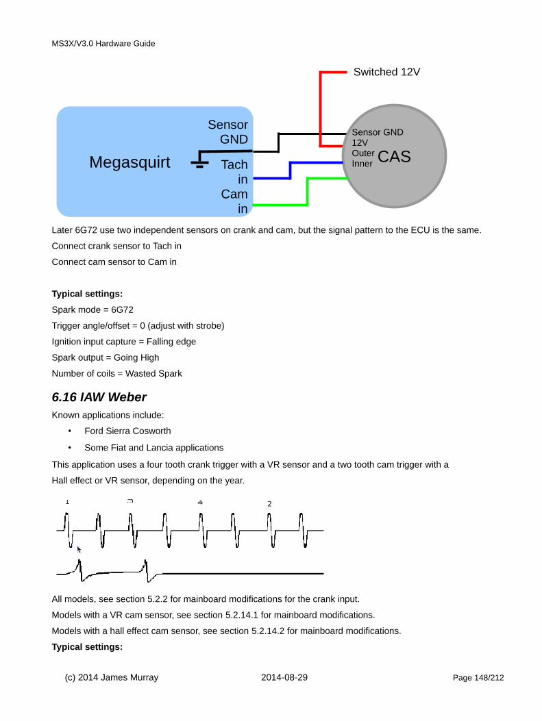
MS3X/V3.0 Hardware Guide
Later 6G72 use two independent sensors on crank and cam, but the signal pattern to the ECU is the same.
Connect crank sensor to Tach in
Connect cam sensor to Cam in
Typical settings:
Spark mode = 6G72
Trigger angle/offset = 0 (adjust with strobe)
Ignition input capture = Falling edge
Spark output = Going High
Number of coils = Wasted Spark
6.16 IAW WeberKnown applications include:
• Ford Sierra Cosworth
• Some Fiat and Lancia applications
This application uses a four tooth crank trigger with a VR sensor and a two tooth cam trigger with a
Hall effect or VR sensor, depending on the year.
All models, see section 5.2.2 for mainboard modifications for the crank input.
Models with a VR cam sensor, see section 5.2.14.1 for mainboard modifications.
Models with a hall effect cam sensor, see section 5.2.14.2 for mainboard modifications.
Typical settings:
(c) 2014 James Murray 2014-08-29 Page 148/212
Megasquirt
SensorGND
Tachin
Cam in
CAS
Sensor GND12VOuterInner
Switched 12V

MS3X/V3.0 Hardware Guide
Spark mode = IAW Weber
Trigger angle/offset = 0 (adjust with strobe)
Ignition input capture = Falling edge
Spark output = Going High
Number of coils = Depends on application
Some applications use a single high current coil, others use coil-on-plug. External ignitors are likely required.
6.17 Mitsubishi CAS 4/1Known applications include:
• Mitsubishi 4G91
• Mazda Protege and 323 with optical distributor
See sections 5.2.3 and 5.2.14.2 for mainboard modifications.
Typical settings:
Spark mode = CAS 4/1
Trigger angle/offset = 0 (adjust with strobe)
Ignition input capture = Falling edge
Spark output = Going High
Number of coils = Depends on application
You will need to set the “Angle between main and return” parameter to the distance between edges of the optical sensor.
Note that if you are not able to get a stable signal off both edges, you should instead use "Toothed
Wheel", mode with "Dual wheel" and 4 teeth at cam speed set.
6.18 Mitsubishi 4G63 (and Miata)Known applications include:
• Mitsubishi 4G63 with distributorless ignition, as used in Eclipse, Galant VR4, and Lancer Evolution
• 1990-1997 Mazda MX5 Miata
(c) 2014 James Murray 2014-08-29 Page 149/212
Megasquirt
SensorGND
Tachin
Cam in
CAS
Sensor GND12VOuterInner
Switched 12V

MS3X/V3.0 Hardware Guide
• 2G 4G63
• pre-1999 Miata (MX5) use a Mitsubishi optical CAS.
• Mitsubishi EVO
4G63 2G CAS
Electrically, the two signals on these CAS are connected the same as a hall sensor and require a pair of pull-up resistors in the wiring harness.
The outer track is considered to be the 'crank' signal and the inner track is the 'cam'.
(c) 2014 James Murray 2014-08-29 Page 150/212
Megasquirt
SensorGND
Tachin
Cam in
CAS
Sensor GND12VOuterInner
Switched 12V
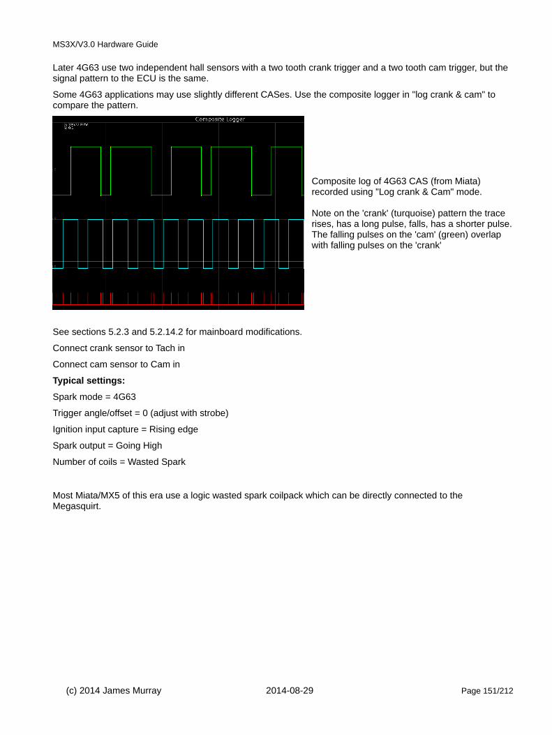
MS3X/V3.0 Hardware Guide
Later 4G63 use two independent hall sensors with a two tooth crank trigger and a two tooth cam trigger, but the signal pattern to the ECU is the same.
Some 4G63 applications may use slightly different CASes. Use the composite logger in "log crank & cam" to compare the pattern.
Composite log of 4G63 CAS (from Miata) recorded using "Log crank & Cam" mode.
Note on the 'crank' (turquoise) pattern the trace rises, has a long pulse, falls, has a shorter pulse.The falling pulses on the 'cam' (green) overlap with falling pulses on the 'crank'
See sections 5.2.3 and 5.2.14.2 for mainboard modifications.
Connect crank sensor to Tach in
Connect cam sensor to Cam in
Typical settings:
Spark mode = 4G63
Trigger angle/offset = 0 (adjust with strobe)
Ignition input capture = Rising edge
Spark output = Going High
Number of coils = Wasted Spark
Most Miata/MX5 of this era use a logic wasted spark coilpack which can be directly connected to the Megasquirt.
(c) 2014 James Murray 2014-08-29 Page 151/212
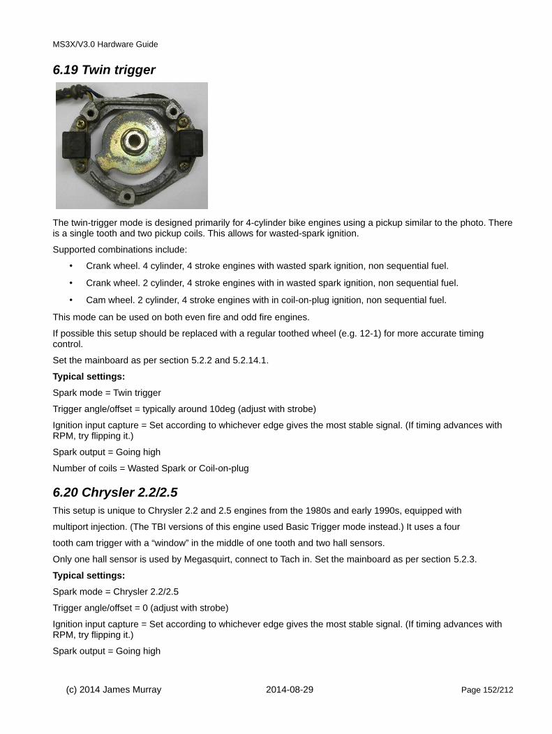
MS3X/V3.0 Hardware Guide
6.19 Twin trigger
The twin-trigger mode is designed primarily for 4-cylinder bike engines using a pickup similar to the photo. Thereis a single tooth and two pickup coils. This allows for wasted-spark ignition.
Supported combinations include:
• Crank wheel. 4 cylinder, 4 stroke engines with wasted spark ignition, non sequential fuel.
• Crank wheel. 2 cylinder, 4 stroke engines with in wasted spark ignition, non sequential fuel.
• Cam wheel. 2 cylinder, 4 stroke engines with in coil-on-plug ignition, non sequential fuel.
This mode can be used on both even fire and odd fire engines.
If possible this setup should be replaced with a regular toothed wheel (e.g. 12-1) for more accurate timing control.
Set the mainboard as per section 5.2.2 and 5.2.14.1.
Typical settings:
Spark mode = Twin trigger
Trigger angle/offset = typically around 10deg (adjust with strobe)
Ignition input capture = Set according to whichever edge gives the most stable signal. (If timing advances with RPM, try flipping it.)
Spark output = Going high
Number of coils = Wasted Spark or Coil-on-plug
6.20 Chrysler 2.2/2.5This setup is unique to Chrysler 2.2 and 2.5 engines from the 1980s and early 1990s, equipped with
multiport injection. (The TBI versions of this engine used Basic Trigger mode instead.) It uses a four
tooth cam trigger with a “window” in the middle of one tooth and two hall sensors.
Only one hall sensor is used by Megasquirt, connect to Tach in. Set the mainboard as per section 5.2.3.
Typical settings:
Spark mode = Chrysler 2.2/2.5
Trigger angle/offset = 0 (adjust with strobe)
Ignition input capture = Set according to whichever edge gives the most stable signal. (If timing advances with RPM, try flipping it.)
Spark output = Going high
(c) 2014 James Murray 2014-08-29 Page 152/212
MS3X/V3.0 Hardware Guide
Number of coils = Single coil
6.21 Renix 44-2-2 (66-2-2-2)Known applications include:
• 1987-1990 Jeep Cherokee 4.0
• Many 1980s era Renault products
This trigger mode came in a four cylinder variation which used 44 base teeth with two gaps 180 degrees apart, and a six cylinder version with 66 base teeth and three gaps 120 degrees apart.
Typically Renault installs utilize a crank sensor only and output to a single coil and distributor.
Wasted spark or coil-on-plug require a single tooth on the cam and a cam sensor. The cam pulse needs to occurbefore the missing tooth region that precedes TDC#1 firing.
Typical settings:
Spark mode = Renix 44-2-2
Trigger angle/offset = 0 (adjust with strobe)
Ignition input capture = Set according to whichever edge gives the most stable signal. (If timing advances with RPM, try flipping it.)
Spark output = Going high
Number of coils = Single coil
6.22 Suzuki SwiftKnown applications include:
• Suzuki Swift engines with a distributor with a VR sensor and 12 irregularly spaced teeth.
A high-current ignition driver will be required.
Typical settings:
Spark mode = Suzuki swift
Trigger angle/offset = 0 (adjust with strobe)
Ignition input capture = Set according to whichever edge gives the most stable signal. (If timing advances with RPM, try flipping it.)
Spark output = Going high
Number of coils = Single coil
6.23 Suzuki Vitara 2.0Known applications include:
• Vitara 2.0
This variant uses an uneven crank wheel with eleven teeth.
6.24 Daihatsu 3cylKnown applications include:
• Some 3 cylinder Daihatsu
This mode is considered experimental. The Daihatsu three cylinder version has 3 equally spaced
(c) 2014 James Murray 2014-08-29 Page 153/212

MS3X/V3.0 Hardware Guide
teeth in a distributor with a fourth tooth adjacent to one of the teeth (3+1) and a VR sensor.
A high-current ignition driver will be required.
Typical settings:
Spark mode = Daihatsu 3cyl
Trigger angle/offset = 0 (adjust with strobe)
Ignition input capture = Set according to whichever edge gives the most stable signal. (If timing advances with RPM, try flipping it.)
Spark output = Going high
Number of coils = Single coil
6.25 Daihatsu 4cylKnown applications include:
• Some 4 cylinder Daihatsu
This mode is considered experimental. The Daihatsu four cylinder version has 4 equally spaced
teeth in a distributor with a fourth tooth adjacent to one of the teeth (4+1) and a VR sensor.
A high-current ignition driver will be required.
Typical settings:
Spark mode = Daihatsu 4cyl
Trigger angle/offset = 0 (adjust with strobe)
Ignition input capture = Set according to whichever edge gives the most stable signal. (If timing advances with RPM, try flipping it.)
Spark output = Going high
Number of coils = Single coil
6.26 VTR1000Known applications include:
• Some Honda V-twin motorcycles
It uses a 12-3 crank trigger with a VR sensor and no cam sensor.
Typical settings:
Spark mode = VTR1000
Trigger angle/offset = 0 (adjust with strobe)
Ignition input capture = Set according to whichever edge gives the most stable signal. (If timing advances with RPM, try flipping it.)
Spark output = Going high
Number of coils = Wasted spark
Must also set 2 cylinders and Odd-fire.
6.27 Rover#1Known applications include:
(c) 2014 James Murray 2014-08-29 Page 154/212
MS3X/V3.0 Hardware Guide
• Rover K-series engines
The crank trigger wheel has 36 base teeth and two one tooth gaps, 180 degrees apart. This only allows a single coil and batch fire injection. Cam input is not supported.
Typical settings:
Spark mode = Rover#1
Trigger angle/offset = 0 (adjust with strobe)
Ignition input capture = Set according to whichever edge gives the most stable signal. (If timing advances with RPM, try flipping it.)
Spark output = Going high
Number of coils = Single coil
6.28 Rover#2Known applications include:
• Rover K-series engines
The crank trigger wheel with 36 base teeth and four one tooth gaps. This only allows a single coil or wasted spark ignition and batch fire or semi-sequential injection. Cam input is not supported.
Typical settings:
Spark mode = Rover#2
Trigger angle/offset = 0 (adjust with strobe)
Ignition input capture = Set according to whichever edge gives the most stable signal. (If timing advances with RPM, try flipping it.)
Spark output = Going high
Number of coils = Single coil or Wasted Spark
6.29 Rover#3Known applications include:
• Rover K-series engines
Similar to Rover #2, but the gaps are two teeth wide and positioned differently. As with Rover #2, supports wasted spark and semi-sequential injection, but does not support cam input.
Typical settings:
Spark mode = Rover#3
Trigger angle/offset = 0 (adjust with strobe)
Ignition input capture = Set according to whichever edge gives the most stable signal. (If timing advances with RPM, try flipping it.)
Spark output = Going high
Number of coils = Single coil or Wasted Spark
6.30 GM7XKnown applications include:
• Some GM four and six cylinder engines with distributorless ignitions.
(c) 2014 James Murray 2014-08-29 Page 155/212
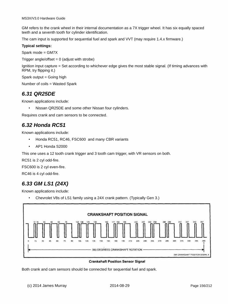
MS3X/V3.0 Hardware Guide
GM refers to the crank wheel in their internal documentation as a 7X trigger wheel. It has six equally spaced teeth and a seventh tooth for cylinder identification.
The cam input is supported for sequential fuel and spark and VVT (may require 1.4.x firmware.)
Typical settings:
Spark mode = GM7X
Trigger angle/offset = 0 (adjust with strobe)
Ignition input capture = Set according to whichever edge gives the most stable signal. (If timing advances with RPM, try flipping it.)
Spark output = Going high
Number of coils = Wasted Spark
6.31 QR25DEKnown applications include:
• Nissan QR25DE and some other Nissan four cylinders.
Requires crank and cam sensors to be connected.
6.32 Honda RC51Known applications include:
• Honda RC51, RC46, FSC600 and many CBR variants
• AP1 Honda S2000
This one uses a 12 tooth crank trigger and 3 tooth cam trigger, with VR sensors on both.
RC51 is 2 cyl odd-fire.
FSC600 is 2 cyl even-fire.
RC46 is 4 cyl odd-fire.
6.33 GM LS1 (24X)Known applications include:
• Chevrolet V8s of LS1 family using a 24X crank pattern. (Typically Gen 3.)
Both crank and cam sensors should be connected for sequential fuel and spark.
(c) 2014 James Murray 2014-08-29 Page 156/212

MS3X/V3.0 Hardware Guide
Set the mainboard as per section 5.2.4 and 5.2.14.3
The coils are wired individually
SpkA = 1, SpkB = 8, SpkC = 7, SpkD = 2, SpkE = 6, SpkF = 5, SpkG = 4, SpkH = 3
Typical settings:
Spark mode = LS1
(c) 2014 James Murray 2014-08-29 Page 157/212

MS3X/V3.0 Hardware Guide
Trigger angle/offset = 0 (adjust with strobe)
Ignition input capture = Falling edge
Spark output = Going high
Number of coils = Coil on plug
6.34 GM LS2 (58X)Known applications include:
• Chevrolet V8s of LS2 family using a 58X crank pattern. (Typically Gen 4.)
Both crank and cam sensors should be connected for sequential fuel and spark.
Set the mainboard as per section 5.2.3 and 5.2.14.2.
The coils are wired as shown in section 6.33
Typical settings:
Spark mode = Toothed wheel
Ignition input capture: Falling edge
Spark output: Going High
Number of coils = Coil on plug
Trigger wheel arrangement = Dual wheel with missing tooth
Trigger wheel teeth = 60
Missing teeth = 2
Tooth #1 angle = 15 (adjust with strobe)
Main wheel speed = Crank wheel
Second Trigger Active on = Falling edge
6.35 YZF1000Known applications include:
• Yamaha YZF1000 / Thunderace
(c) 2014 James Murray 2014-08-29 Page 158/212
MS3X/V3.0 Hardware Guide
• Yamaha FZR1000
• Yamaha FZR750
• Yamaha FZ700
Typical settings:
Spark mode = YZF1000
Trigger angle/offset = 0 (adjust with strobe)
Ignition input capture = Falling edge
Spark output = Going high
6.36 HD 32-2Known applications include:
• Harley Davidson with 32-2 crank trigger
A VR sensor is used on the crank trigger. As standard there is no cam sensor. Phase detection is possible using the MAP sensor.
Typical settings:
Spark mode = HD 32-2
Trigger angle/offset = 0 (adjust with strobe)
Ignition input capture = Set according to whichever edge gives the most stable signal. (If timing advances with RPM, try flipping it.)
Spark output = Going high
Cam sensor = MAP
The front cylinder is considered cyl#1 and therefore connects to SpkA. Sequential fuel is allowed.
6.37 Miata 36-2Known applications include:
• Mazda Miata (MX5) 99-05 fitted with aftermarket 36-2 crank trigger
Typical settings:
Spark mode = Miata 36-2
Trigger angle/offset = 0 (adjust with strobe)
Ignition input capture = Set according to whichever edge gives the most stable signal. (If timing advances with RPM, try flipping it.)
Spark output = Going high
Both crank and cam sensors are VR type and need to be connected.
6.38 Fiat 1.8 16VKnown applications include:
• Fiat with 1.8 16V engine
Typical settings:
Spark mode = Fiat 1.8 16V
(c) 2014 James Murray 2014-08-29 Page 159/212

MS3X/V3.0 Hardware Guide
Trigger angle/offset = 0 (adjust with strobe)
Ignition input capture = Set according to whichever edge gives the most stable signal. (If timing advances with RPM, try flipping it.)
Spark output = Going high
Uses an irregular six tooth crank trigger and a three tooth cam trigger, with a VR crank trigger and Hall effect
cam signal. Both sensors need to be connected.
Set the mainboard as per section 5.2.2 and 5.2.14.1.
6.39 OptisparkKnown applications include:
• Chevrolet LT1 variants
• Nissan VH45 V8
The Optispark system was used on GM vehicles from 1993 to 1997 on LT1, LT4 and L99 applications. Internallyit uses a Mitsubishi / Nissan derived optical trigger arrangement. There is a "hi-res" track of 360 slits and a "low-res" track of 8 slots of varying length. The pickup design is sound, but the high-tension side can be problematic with the "correct-a-cap" design - especially if a high energy aftermarket ignition system is used.
The Megasquirt-3 Optispark decoder uses both low and high resolution tracks for improved ignition accuracy. (Most other aftermarket implementation only use the low resolution track.) The system allows for sequential fuel and the single coil as per the original install. However, as an enhancement the single coil can be replaced by a wasted-spark or coil-on-plug setup which would eliminate the troublesome high-tension cap.
The Optispark requires a fused 12V supply. This can be tapped into the same 12V supply as the Megasquirt. The Ground connection should be run to the sensor ground at the Megasquirt.
The high and low resolution tach signals each require a "pull up" resistor to operate correctly. The unit has been tested with 330R resistors as shown:
(c) 2014 James Murray 2014-08-29 Page 160/212

MS3X/V3.0 Hardware Guide
Set the mainboard as per section 5.2.4
Typical settings:
Spark mode = Optispark
Trigger angle/offset = Start at 0 deg - adjust while strobing timing.
Ignition input capture = Falling edge
Number of coils = Single coil
Flip polarity on hi-res should be set to "Inverted"
6.40 Nissan SR20Known applications include:
• RWD version of the SR20DET with coil on plug ignition.
• CA18
These engines use an optical CAS with four unequally sized slots and a row of 360 slots.
The CAS requires a fused 12V supply. This can be tapped into the same 12V supply as the Megasquirt. The Ground connection should be run to the sensor ground at the Megasquirt.
(c) 2014 James Murray 2014-08-29 Page 161/212

MS3X/V3.0 Hardware Guide
The high and low resolution tach signals each require a "pull up" resistor to operate correctly. The unit has been tested with 330R resistors as shown:
Set the mainboard as per section 5.2.4
Typical settings:
Spark mode = Nissan SR20
Trigger angle/offset = Start at 0 deg - adjust while strobing timing.
Ignition input capture = Falling edge
Number of coils = Coil on plug
Flip polarity on hi-res should be set to "Inverted"
6.41 Nissan RB25Known applications include:
• RB25
• RB26
(c) 2014 James Murray 2014-08-29 Page 162/212

MS3X/V3.0 Hardware Guide
These engines use an optical CAS with six unequally sized slots and a row of 360 slots.
The CAS requires a fused 12V supply. This can be tapped into the same 12V supply as the Megasquirt. The Ground connection should be run to the sensor ground at the Megasquirt.
The high and low resolution tach signals each require a "pull up" resistor to operate correctly. The unit has been tested with 330R resistors as shown:
Set the mainboard as per section 5.2.4
Typical settings:
Spark mode = Nissan RB25
Trigger angle/offset = Start at 0 deg - adjust while strobing timing.
Ignition input capture = Falling edge
Number of coils = Coil on plug
Flip polarity on hi-res should be set to "Inverted"
(c) 2014 James Murray 2014-08-29 Page 163/212

MS3X/V3.0 Hardware Guide
6.42 Honda Acura V6Known applications include:
• Honda and Acura J series V6 motors.
This mode uses a crank trigger with 24 base teeth and two separate missing teeth, along with a cam sensor.
Typical settings:
Spark mode = Honda Acura
Trigger angle/offset = 0 (adjust with strobe)
Ignition input capture = Set according to whichever edge gives the most stable signal. (If timing advances with RPM, try flipping it.)
Spark output = Going high
6.43 VQ35DEKnown applications include:
• Nissan 350Z and other VQ35DE applications
Requires crank and cam sensors to be connected.
Typical settings:
Spark mode = VQ35DE
Trigger angle/offset = 0 (adjust with strobe)
Ignition input capture = Set according to whichever edge gives the most stable signal. (If timing advances with RPM, try flipping it.)
Spark output = Going high
6.44 Jeep 2000Known applications include:
• 1991-2000 Jeep 4.0 inline six
• Dodge Avenger 2.5 V6
• Some Chrysler V6 minivans
This mode has thee sets of four notches on the crank trigger and a one tooth distributor trigger.
Requires crank and cam sensors to be connected.
Typical settings:
Spark mode = Jeep 2000
Trigger angle/offset = 0 (adjust with strobe)
Ignition input capture = Set according to whichever edge gives the most stable signal. (If timing advances with RPM, try flipping it.)
Spark output = Going high
6.45 Jeep 2002Known applications include:
• 3.7 V6
(c) 2014 James Murray 2014-08-29 Page 164/212
MS3X/V3.0 Hardware Guide
This mode appears on the last run of the Jeep 4.0 inline six, with coil packs instead of the distributor. Uses the same crank trigger as the Jeep 2000 mode, but with a more complex cam pattern.
Requires crank and cam sensors to be connected.
Typical settings:
Spark mode = Jeep 2002
Trigger angle/offset = 0 (adjust with strobe)
Ignition input capture = Set according to whichever edge gives the most stable signal. (If timing advances with RPM, try flipping it.)
Spark output = Going high
6.46 Zetec VCTKnown applications include:
• 3.7 V6
Used on Ford Zetec and other four cylinder engines with variable valve timing. Features a 36-1 crank trigger likemany other Fords, but a five tooth cam wheel instead of a one tooth. Uses VR sensors on both, and supports full sequential operation and variable valve timing.
Requires crank and cam sensors to be connected.
Typical settings:
Spark mode = Zetec VCT
Trigger angle/offset = 0 (adjust with strobe)
Ignition input capture = Set according to whichever edge gives the most stable signal. (If timing advances with RPM, try flipping it.)
Spark output = Going high
6.47 Flywheel tri-tachKnown applications include:
• Early 1980s Porsche 911
• Porsche 944 Turbo (951)
• 1986 and earlier BMW 325e
• E30 chassis BMW M3 with S14 motor
• Many 1980s and early 1990s Audis
This application uses a VR sensor that counts flywheel teeth, with a second flywheel sensor that reads a single post and, in most implementations, a cam sensor. Note that the number of teeth is hard coded for a specific number of cylinders. With a cam sensor, this will support full sequential.
Most installs require three tach inputs
- flywheel tooth sensor (VR)
- flywheel reset pin sensor (VR)
- distributor sensor (hall)
This mode is considered experimental.
Number of teeth Number of cylinders
(c) 2014 James Murray 2014-08-29 Page 165/212

MS3X/V3.0 Hardware Guide
135 5
135 6
136 8
132 4
130 4
Typical settings:
Spark mode = Flywheel tri-tach
Trigger angle/offset = 0 (adjust with strobe)
Ignition input capture = Set according to whichever edge gives the most stable signal. (If timing advances with RPM, try flipping it.)
Spark output = Going high
6.48 2JZ VVTiKnown applications include:
• Lexus IS300
• many 2000 and later Toyota six cylinder engines with VVTi.
This uses a 36-2 crank trigger and a three tooth cam trigger, with VR sensors. Supports sequential injection and variable valve timing.
Both sensors need to be connected for VVT.
Typical settings:
Spark mode = 2JZVVTi
Trigger angle/offset = 0 (adjust with strobe)
Ignition input capture = Set according to whichever edge gives the most stable signal. (If timing advances with RPM, try flipping it.)
Spark output = Going high
6.49 Honda TSX/D17Known applications include:
• D17 engine
Uses a 12 tooth crank sensor with one tooth added for a total of 13 real teeth, combined with a cam sensor. Thisallowed Honda to add continuously variable valve timing. Uses VR sensors.
Both sensors need to be connected for VVT.
Typical settings:
Spark mode = Honda TSX/D17
Trigger angle/offset = 0 (adjust with strobe)
Ignition input capture = Set according to whichever edge gives the most stable signal. (If timing advances with RPM, try flipping it.)
Spark output = Going high
(c) 2014 James Murray 2014-08-29 Page 166/212

MS3X/V3.0 Hardware Guide
6.50 Mazda6 2.3 VVTKnown applications include:
• Mazda 6 with VVT
This one has a 36-1 crank trigger and an uneven cam pattern.Typical settings:
Spark mode = Mazda6 VVT
Trigger angle/offset = 0 (adjust with strobe)
Ignition input capture = Set according to whichever edge gives the most stable signal. (If timing advances with RPM, try flipping it.)
Spark output = Going high
6.51 Viper V10 (gen 2)Known applications include:
• 1996 and later Vipers and V10 Rams with JTEC ECU
This one has a crank trigger with five groups of two teeth. A cam sensor is also required, with a one tooth triggerwheel.
Coil-on-plug is beyond the scope without MS3X, so wasted spark should be used.
Factory Chrysler coils are high-current type and require internal or external ignitors.
Typical settings:
Spark mode = Viper V10
Trigger angle/offset = 0 (adjust with strobe)
Ignition input capture = Set according to whichever edge gives the most stable signal. (If timing advances with RPM, try flipping it.)
Spark output = Going high
6.52 Viper V10 (gen 1)Known applications include:
• 1995 and earlier Vipers and V10 Rams.
This one has a crank trigger with five groups of two teeth. A cam sensor is also required, with a one, two tooth trigger wheel.
Coil-on-plug is beyond the scope without MS3X, so wasted spark should be used.
Factory Chrysler coils are high-current type and require internal or external ignitors.
Typical settings:
Spark mode = Viper V10 Gen1
Trigger angle/offset = 0 (adjust with strobe)
Ignition input capture = Set according to whichever edge gives the most stable signal. (If timing advances with RPM, try flipping it.)
Spark output = Going high
(c) 2014 James Murray 2014-08-29 Page 167/212

MS3X/V3.0 Hardware Guide
6.53 Honda K24A2Known applications include:
• Honda K24A2
This works very similarly to the TSX/D17 mode, but the crank phasing is different.
Typical settings:
Spark mode = K24A2
Trigger angle/offset = 0 (adjust with strobe)
Ignition input capture = Set according to whichever edge gives the most stable signal. (If timing advances with RPM, try flipping it.)
Spark output = Going high
(c) 2014 James Murray 2014-08-29 Page 168/212

MS3X/V3.0 Hardware Guide
7: ThrottlesThe major influence on engine speed on a spark-ignition (gasoline) engine is air-flow. (Contrast a compression-ignition (diesel) engine where there is no throttling and fuel flow governs engine speed.)
For normal running the main throttle plates control the air-flow. At idle an idle valve can be used to provide controlled flow, or a throttle stop screw can be used on the main throttles to allow a low flow during "closed" throttle conditions.
Throttles need to be appropriately sized for the engine displacement and RPM range. Too small and the engine will "run out of steam" at higher RPMs. Too large and tiny throttle movement will allow a large airflow giving jerkylow-load operation.
There are a wide range of throttles available. Most factory EFI installs use a single throttle plate. Many aftermarket companies offer USA style 4 barrel carburettor replacement throttle-bodies. Another option that is particularly common on 4-cylinder engines is to fit bike throttle bodies.
Independent throttle body installs free up the most power from the engine, but will need to be balanced (equal airflow for each throttle) and the MAP signal will be weak - consider using "ITB mode" or "Alpha-N."
All throttles will need to be fitted with a TPS if not already included.
Example 4150 style 4-barrel EFI throttle body.
(c) 2014 James Murray 2014-08-29 Page 169/212

MS3X/V3.0 Hardware Guide
8: Optional Hardware
8.1 Expansion boardsThe Megasquirt was designed with enough inputs and outputs to control a simple engine. If additional inputs and outputs are desired, an add-on expansion board may be used.
The Megasquirt has CAN communications that allow the simple 2-wire connection.
Example expansion boards are:
• CANEGT - allows K-type thermocouples for per-cylinder exhaust gas temperature monitoring
• GPIO/ trans - allows control of electronically shifted automatic transmissions
• IO-Expander - DIY assembled product for additional analogue input, relay outputs, GPS, accelerometer,thermocouple.
• Dashes / loggers - many vendors dashboards are compatible with the Megasquirt-2 data stream.
For specific product features and configuration details, please refer to your supplier's documentation.
9: Example wiring
9.1 Sequential fuel and sparkNote that injector and coil outputs are always wired in firing order.
9.1.1 Inline 4 : 1-3-4-2
(c) 2014 James Murray 2014-08-29 Page 170/212

MS3X/V3.0 Hardware Guide
(c) 2014 James Murray 2014-08-29 Page 171/212

MS3X/V3.0 Hardware Guide
(c) 2014 James Murray 2014-08-29 Page 172/212

MS3X/V3.0 Hardware Guide
9.1.2 V6 : 1-6-5-4-3-2
(c) 2014 James Murray 2014-08-29 Page 173/212

MS3X/V3.0 Hardware Guide
9.1.3 Inline 6 : 1-5-3-6-2-4
(c) 2014 James Murray 2014-08-29 Page 174/212
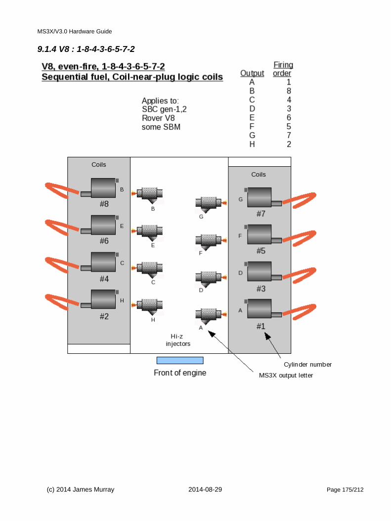
MS3X/V3.0 Hardware Guide
9.1.4 V8 : 1-8-4-3-6-5-7-2
(c) 2014 James Murray 2014-08-29 Page 175/212

MS3X/V3.0 Hardware Guide
9.1.5 V8 : 1-8-7-2-6-5-4-3
(c) 2014 James Murray 2014-08-29 Page 176/212
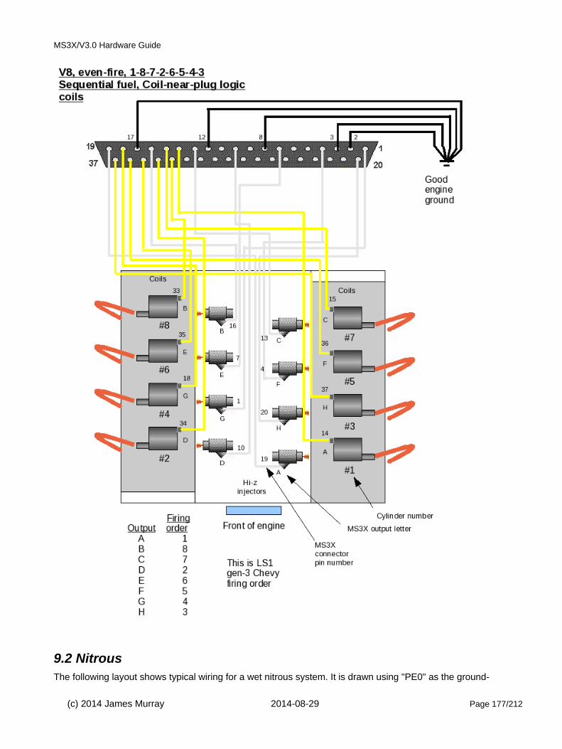
MS3X/V3.0 Hardware Guide
9.2 NitrousThe following layout shows typical wiring for a wet nitrous system. It is drawn using "PE0" as the ground-
(c) 2014 James Murray 2014-08-29 Page 177/212

MS3X/V3.0 Hardware Guide
switched input and IAC1/2 as the stage 1 and 2 outputs.
With the appropriate software settings other pins may be used for inputs and/or FIDLE+D15 may be used as theoutputs.
Optionally a double pole switch can be used as the master switch. Use one set of terminals for the +12V supply and the second set for the ground input and then omit the top relay
9.3 Other examplesMore to follow.
10: Further informationFor additional information or to join the community forums for Megasquirt, please visit:
www.msextra.com
(c) 2014 James Murray 2014-08-29 Page 178/212

MS3X/V3.0 Hardware Guide
11: Appendix A SchematicsThe copyrighted Megasquirt schematics are provided for repair, interfacing and education purposes only.
(c) 2014 James Murray 2014-08-29 Page 179/212
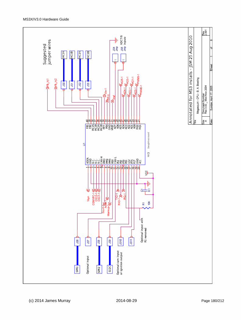
MS3X/V3.0 Hardware Guide
(c) 2014 James Murray 2014-08-29 Page 180/212
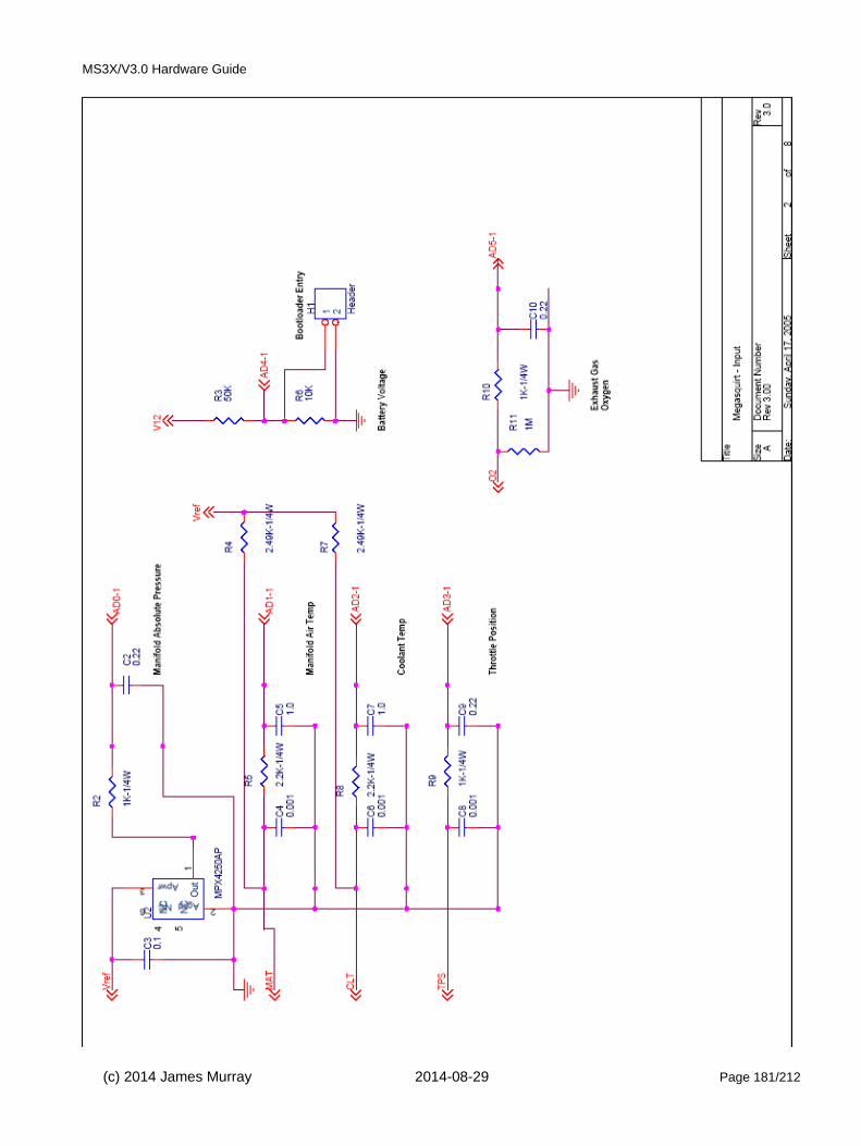
MS3X/V3.0 Hardware Guide
(c) 2014 James Murray 2014-08-29 Page 181/212

MS3X/V3.0 Hardware Guide
(c) 2014 James Murray 2014-08-29 Page 182/212

MS3X/V3.0 Hardware Guide
(c) 2014 James Murray 2014-08-29 Page 183/212

MS3X/V3.0 Hardware Guide
(c) 2014 James Murray 2014-08-29 Page 184/212

MS3X/V3.0 Hardware Guide
(c) 2014 James Murray 2014-08-29 Page 185/212

MS3X/V3.0 Hardware Guide
(c) 2014 James Murray 2014-08-29 Page 186/212

MS3X/V3.0 Hardware Guide
(c) 2014 James Murray 2014-08-29 Page 187/212

MS3X/V3.0 Hardware Guide
There are no plans to publish the schematics for the MS3 card.
(c) 2014 James Murray 2014-08-29 Page 188/212
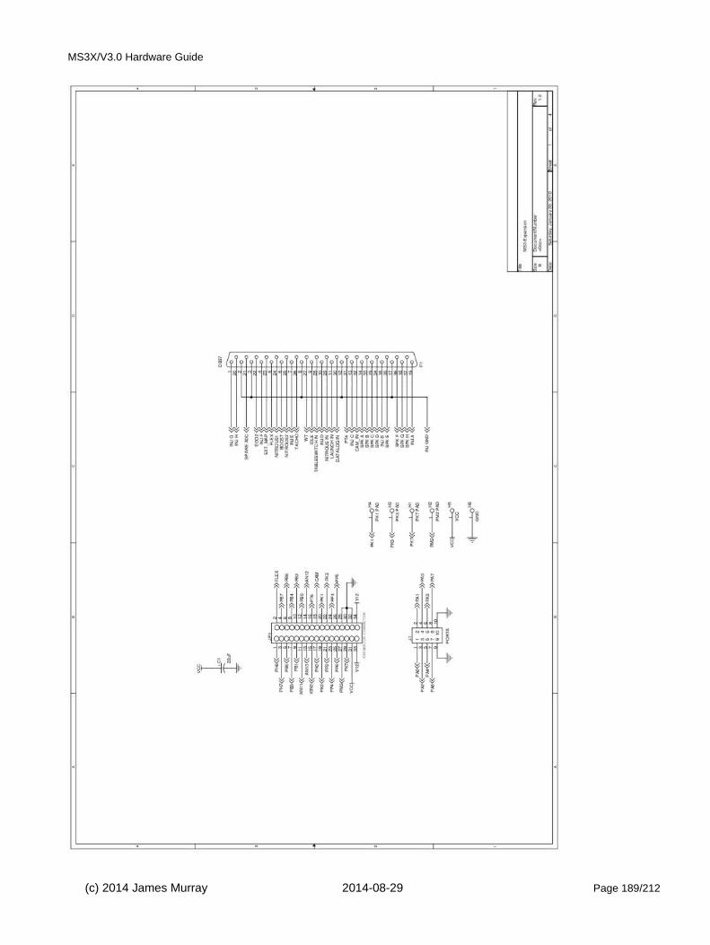
MS3X/V3.0 Hardware Guide
(c) 2014 James Murray 2014-08-29 Page 189/212
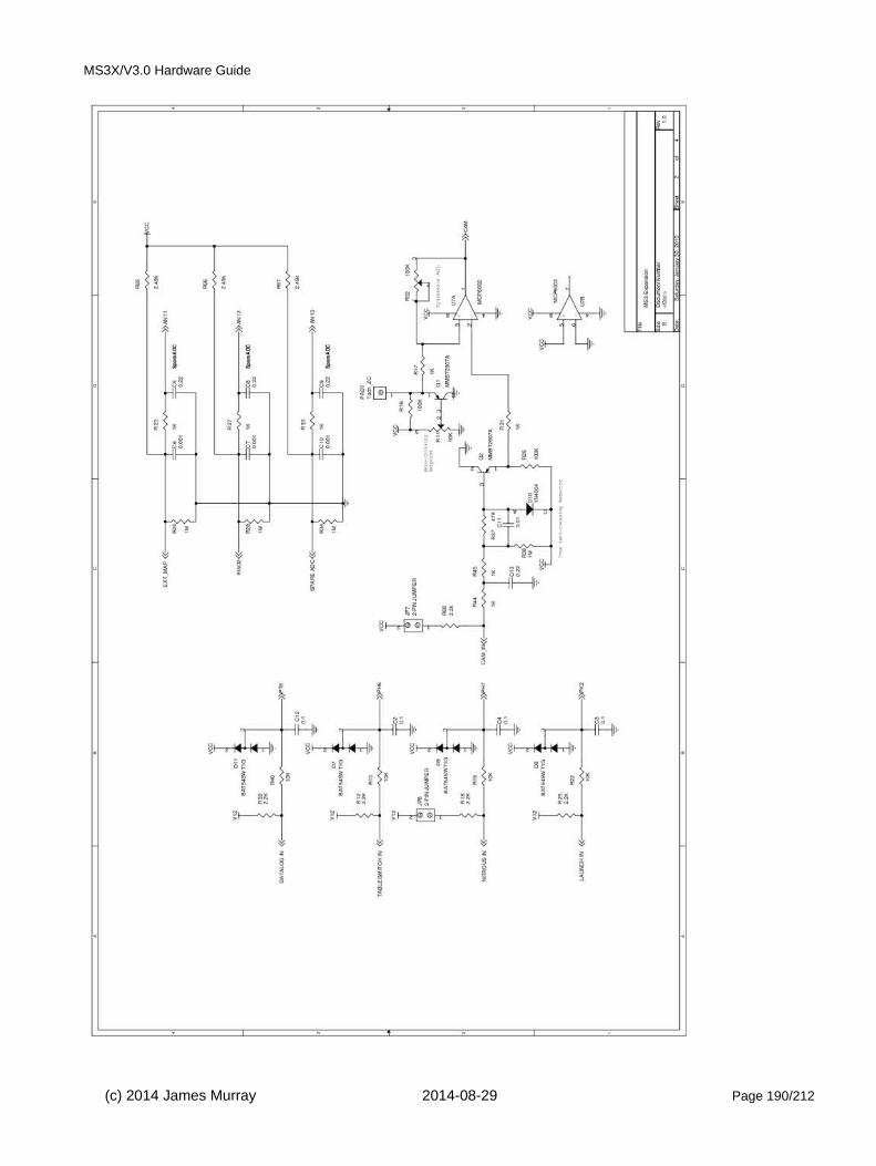
MS3X/V3.0 Hardware Guide
(c) 2014 James Murray 2014-08-29 Page 190/212

MS3X/V3.0 Hardware Guide
(c) 2014 James Murray 2014-08-29 Page 191/212
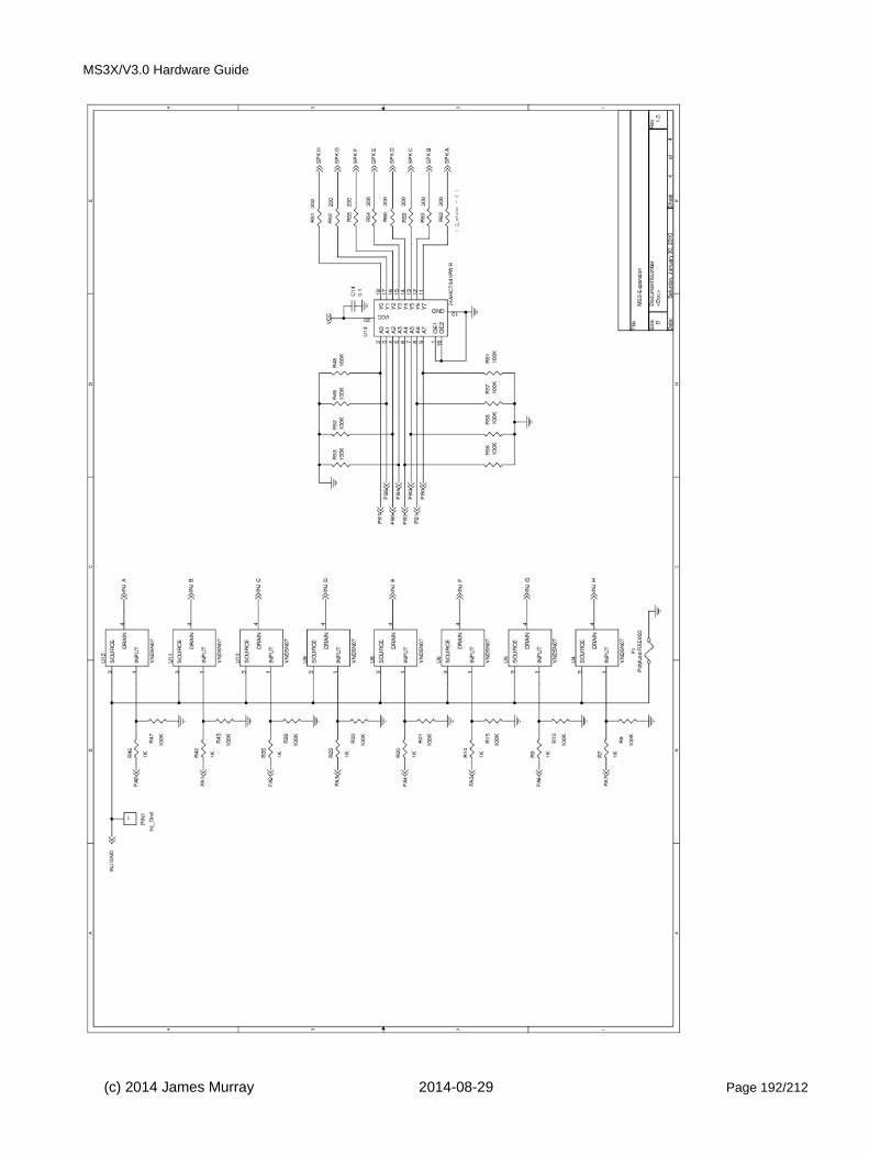
MS3X/V3.0 Hardware Guide
(c) 2014 James Murray 2014-08-29 Page 192/212

MS3X/V3.0 Hardware Guide
12: Appendix B: junkyard guide to finding EDIS
12.1 North America - EDIS4Early to mid 1990s Ford Escort/ Mercury Tracer with base 1.9L SOHC engine were fitted with the EDIS4 system. You can tell the engine because it has a tubular aluminium (NOT cast) inlet manifold.
The EDIS4 module is mounted just behind the fuse box on the drivers side of the engine bay, it has a label on the plug that says EDIS4. The bolts are 10mm AF. You are advised to remove the fuse box first for easier access. Cut off as much as the harness as you can.
Looking toward the passenger side end of the engine, the VR sensor is above and to the left of the end of the crankshaft. The easiest way to access the sensor is to remove the front wheel (if it's not already removed), lie onyour back, and reach up from the bottom to access the sensor mounting bolts. The bolts are either small metric or star bit. Once it's off, the cable is most easily cut from the top.
The crank pulley bolt is 19mm. You will need to stop engine from turning, various methods have been suggested. 1) remove the head, put some rocks into the bore and refit the head. 2) remove a spark plug and puta long bar down the hole 3) remove a plug from cylinder with piston at BTDC and coil in some rope, remove rope when finished.
(c) 2014 James Murray 2014-08-29 Page 193/212

MS3X/V3.0 Hardware Guide
12.2 Europe - EDIS41989-1993 Fiesta XR2i 1.6
1990-1992 Fiesta RS turbo
1989-1994 Escort 1.6i
1990-1994 Orion 1.6i
Modules are all in the engine bay and typically located in the middle of the bulkhead or the right hand side as you face the car.
Known part numbers are: 89FB-12K072-AC, 91AB-12K072-AA
Orion CVH MPI
Fiesta / crossflow Escort
(c) 2014 James Murray 2014-08-29 Page 194/212

MS3X/V3.0 Hardware Guide
Mondeo with 1800/2000 engine.
Location of the VR sensor varies. On the small CVH engines it pokes through the rear flange of the engine towards the flywheel. 1.8CVH Sierra has one on the front. 2.0DOHC Sierra/ Granada is in the block at the left side way below the inlet manifold. Duratec V6 (Mondeo) is mounted near the front, it also has a cam sensor thatworks too.
The mounting bolts are either small metric or star bit.
Escort / Fiesta location on engine flange above starter.
Do not confuse with the ESC II hybrid module which has a vacuum tube and comes on the carb model cars.
There is also an aluminium one to avoid as well.
(c) 2014 James Murray 2014-08-29 Page 195/212

MS3X/V3.0 Hardware Guide
12.3 Europe - EDIS6up to 1995ish Mondeo V6 automatic
Ford/Cosworth Granada Scorpio 24v V6
Module located rear left of engine bay as you face the car.
Known part numbers are: 90GB-12K072-AB
12.4 Europe - EDIS8Chances of finding one of these in a scrapyard are very low! Not known to have been installed on any Europeanbuilt vehicles. Your best bet is either to import a module from the USA or buy new. I would suggest buying the other bits locally.
For connectors try one off another car if all the wires are in use or one off an ESC module. The number of wires used in the connector varies so check they are all there!
There is a possibility of using 2 EDIS4 modules to drive a V8. But now that the MS ECU can directly drive 4 coils(V8 in wasted spark) this is no longer necessary.
12.5 Europe - 36-1 trigger disc The 1.8CVH Sierra has a useful disc pressed onto the back of the crank pulley
All of the other CVH installs have the trigger teeth cut into the flywheel and so are useless.
For a scrap yard trigger disc, remove from 1.8CVH Sierra. You will need to stop engine from turning, various methods have been suggested.
1) remove the head, put some old bolts or other junk into the bore and refit the head.
2) remove a spark plug and put a long bar down the hole
3) remove a plug from cylinder with piston at BTDC and coil in some rope, remove rope when finished
4) Jam something into the flywheel teeth
If you are after a pressed steel disc, try part no. 1078767 from Ford, this came on the 16v DOHC Granada engines. Alternatively many retailers sell universal 36-1 trigger wheels.
(c) 2014 James Murray 2014-08-29 Page 196/212

MS3X/V3.0 Hardware Guide
12.6 Europe - VR sensor
Usually it is easiest to get from the same vehicle as the EDIS module so the wiring harness wiring colors match.
Or any vehicle with a trigger disc will yield one, so CVH Fiesta/Escort/Orion or Fiesta with Valencia (crossflow) engine with ESCII hybrid, DOHC Sierra/Granada, Mondeo.
12.7 World - Coilpack(s)Fords from the EDIS era and beyond use suitable coilpacks.
(c) 2014 James Murray 2014-08-29 Page 197/212
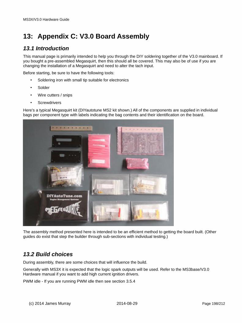
MS3X/V3.0 Hardware Guide
13: Appendix C: V3.0 Board Assembly
13.1 IntroductionThis manual page is primarily intended to help you through the DIY soldering together of the V3.0 mainboard. If you bought a pre-assembled Megasquirt, then this should all be covered. This may also be of use if you are changing the installation of a Megasquirt and need to alter the tach input.
Before starting, be sure to have the following tools:
• Soldering iron with small tip suitable for electronics
• Solder
• Wire cutters / snips
• Screwdrivers
Here's a typical Megasquirt kit (DIYautotune MS2 kit shown.) All of the components are supplied in individual bags per component type with labels indicating the bag contents and their identification on the board.
The assembly method presented here is intended to be an efficient method to getting the board built. (Other guides do exist that step the builder through sub-sections with individual testing.)
13.2 Build choicesDuring assembly, there are some choices that will influence the build.
Generally with MS3X it is expected that the logic spark outputs will be used. Refer to the MS3base/V3.0 Hardware manual if you want to add high current ignition drivers.
PWM idle - If you are running PWM idle then see section 3.5.4
(c) 2014 James Murray 2014-08-29 Page 198/212

MS3X/V3.0 Hardware Guide
13.3 Assembly1) It is assumed you can already solder, if not then there are lots of good articles that explain how to do that on the internet already, so we won't cover that here.
If you are inexperienced at soldering then assembling the Megasquirt simulator (stim) or another electronics kit first is strongly advised. Some components on the board are quite fiddly and one small solder-bridge is enough to cause big problems.
For self assembly it is expected that you will have bought a kit from one of the recommended suppliers. The description below assumes all of the same valued components are in bags (e.g. R39 and R40 are the same value, so would be in one bag, C16 and C17 are the same values, so would be in another bag, etc) as they would be from a MegaSquirt kit supplier.
(While it is possible to buy all the parts individually, for a single Megasquirt build this is likely to be extremely time consuming and not worth the effort - just buy a complete kit, really.)
2) Clear space on a work bench with good lighting. Get your tools together - soldering iron, solder, stand, wire snippers etc.
3) Start the build by soldering in the 2 connectors (37 pinned and 9 pinned items)
4) Next get all the bags of resistors together, keeping them in the bags. (R1, etc)
Find R12, R37, R38, R43, R39 and R57. Put them out of the way for the moment as you don’t need them yet.R57 is never needed and should not actually be part of the kit.
(c) 2014 James Murray 2014-08-29 Page 199/212

MS3X/V3.0 Hardware Guide
5) Now solder all of the rest of the ordinary resistors in place - soldering from the top. Note: There is no polarity for resistors, so they can fit in either way round.
6) Now solder in the two variable resistors R52 and R56 ensure the adjusting screw matches the legend on the silkscreen. Even though these look identical, they are different values so do not mix them up. Solder from below.
7) Next get all the bags of diodes together, keeping them in the bags. (D1, etc) Note, ALL of the diodes have a strip on them that MUST go the same side as the strip marked on the board!
8) Find D1 and D2 and put them to one side. Keep both these diodes as you may need them (FIdle output mods). Note, D1 may need installing if your using a coil -ve triggering setup.
9) Find D8 and keep this to one side as you may need it later. (It's a 22V Zener)
10) -
11) Next you can fit all the rest of the diodes.
(c) 2014 James Murray 2014-08-29 Page 200/212
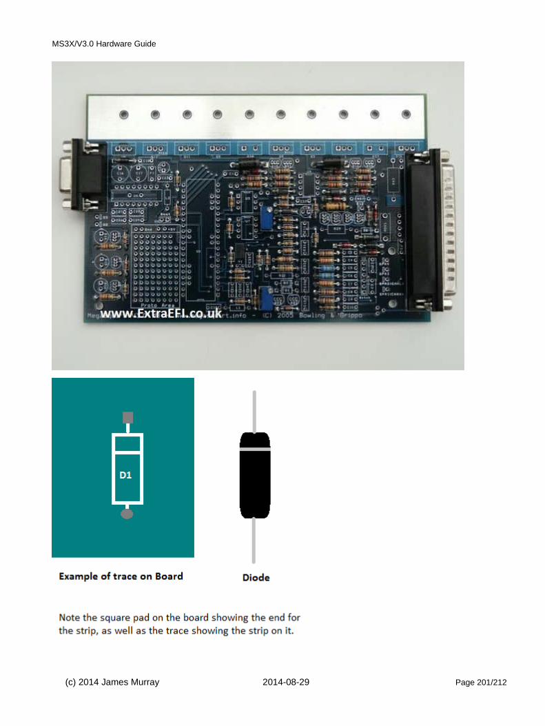
MS3X/V3.0 Hardware Guide
(c) 2014 James Murray 2014-08-29 Page 201/212

MS3X/V3.0 Hardware Guide
12) Next get all the bags of capacitors together, keeping them in the bags (C1, etc).
If you’re using the coil –ve as the trigger input go to step 14 (This is rare now.) Note that you CANNOT trigger from coil negative if you are trying to run ignition or sequential fuel - you need a toothed-wheel arrangement.
13) As long as you’re NOT using the coil –ve as the trigger input (Fuel only) find C30 and instead install it in H1/Boot (This adds smoothing to the battery voltage measurement and reduces the chance of noise getting injected into the CPU from the 12V line.)
14) Find C22 and C14, C16 and C17. Solder these in. Note, these are polarised, ensure the lead with the “+” next to it on the component goes into the square pad on the board, this is also labeled with a ”+” on the board.
15) Now solder all the rest of the capacitors in. Solder from above.
(c) 2014 James Murray 2014-08-29 Page 202/212

MS3X/V3.0 Hardware Guide
15B) Solder in the two polyfuses F1 and F2. Solder in the two inductors L1 and L2, leave a little gap underneath.Solder in MOV1 (looks like a big round capacitor.) (Not shown installed in this photo.)
16) Now find the bag with all the chips in it, U6, U3, U7, U4 and the 40 pin socket for U1. Solder these in place, be careful to get them the correct way round! Also, be sure not to mix up U4 (IXDI404) and U7 (MC33072)
U7 could be one of two parts, the LM2904 works in 99% of cases though is being phased out and replaced with a substitute (MC33072) that has been shown to solve problems that a very small number of vehicles (e.g. LS1) may experience.
Note, the notch in the component must line up with the notch shown on the board. For the chips it usually works well to solder one leg in from above (to hold the part in place) then turn the board over and solder in all legs from below for a better joint and less heat into the chip.
17) Find Q16, (Ignition Transistor), D14, D15 and D16 (LEDs) Q4 and Q20 (small transistors) and MS3 CPU card. Put these to one side but don’t lose them!!
18) Now place the metal strip (heatsink) in place and start fitting the main power components (U5, Q12, Q11, Q5, R38, Q9, Q3, Q1, R37), remembering Q9 and Q12 have a piece of mica insulation under them to stop them touching the heatsink!
Note, you can temporarily fit a couple of screws to hold the heatsink in place whilst you put the parts in. All power components should be fitted with a smear of thermal grease.
See step 28 before installing Q16.
TIP125, TIP122, BIP373 require a mica insulator.
(c) 2014 James Murray 2014-08-29 Page 203/212

MS3X/V3.0 Hardware Guide
Without mica
With mica
(c) 2014 James Murray 2014-08-29 Page 204/212

MS3X/V3.0 Hardware Guide
19) Find Y1 (crystal) This is not needed for MS3, but for completeness you can fit it so that the body of the crystal lays on the metal pad above the holes. You should glue this to the board or very carefully solder it so it doesn't move about.
20) You can now fit all the other components (polyfuses, MOV etc), except for those that you put to one side! I fitthe MAP sensor last, don’t forget to bolt it in place with the plastic screws then solder it in once it's secure. It mounts on the underside of the board. Note, if using metal screws, don’t tighten them up too much or the sensor
(c) 2014 James Murray 2014-08-29 Page 205/212

MS3X/V3.0 Hardware Guide
case will distort and read incorrectly. This is installed with the writing facing you, the 'round' side goes towards the board. One of the pins has a small notch out of it which goes in the hole with 'notch' next to it.
When installing the small transistors, the rounded side of the package aligns with the rounded symbol on the circuit board. To reduce the change of the leads becoming bridged, bend the leads outwards slightly and solder the middle lead first. Double check for solder-bridges with a magnifying glass after assembly.
Note, if using the SPR1-4 connections you should install the jumper wires before the MAP sensor.
21) R37 and R38 are 'sense' resistors for the current limiting circuits on the injector drivers. Normally these should be installed.
(If, however, you prefer to do without the current limiting and want to make two spaces on the heatsink bar, then you can instead link out R37 and R38 by soldering a copper wire between the 2 holes in each. Ensure the link isflat to the board as you may need a component on the heat sink later on in the build. Remember that without these current sense resistors, there is no over-current protection on the injector circuits.)
22) R43 is intended to allow coil current to be measured if you are using the Q16 high current coil driver. Unless you have access to an oscilloscope and plan on performing this test you won't need it. Either install R43 or link itout.
23) Solder a wire between s12c and JS9, this feeds the stepper motor driver on the MS3 CPU card. Even if you are not going to use a stepper idle valve, it is needed to use those outputs for other purposes. Do install it.
13.4 Testing Stage
(c) 2014 James Murray 2014-08-29 Page 206/212

MS3X/V3.0 Hardware Guide
24) The board is now built to a basic level and is ready for a few tests:
a) Start by looking at ALL of the diodes and ensure they are the right way round.
b) Check that you fitted the mica insulators under Q9 and Q12 on the heatsink and that they look OK.
c) Now you can plug it into your Stim (in the absence of a stim, you need a loom-pigtail and a 12V DC supply with a low value fuse e.g. 1A. Check the external wiring diagram, +12V goes to pin 28 and ground to any of pins1,2,7-19 ) and measure the voltage on the 40 pin connector U1:
Put the -ve probe of you're voltmeter on pin 32 of the 40pin connector (U1) Note, this is WITHOUT the CPU card in place!
Put the +ve probe onto pin 20 (Top pin right side)
Ensure you read 5V (+- 0.1V)
d) Keep the +ve probe on pin 20 and move the -ve probe to pin 19 and pin 2, ensure you have 5V on the meter for both measurements. If its OK go to the next step (25).
e) If you don't get 5V then put the -ve probe on the 0V on the proto area and put the +ve probe onto the left pin of U5 (top left hand side on heatsink) check the voltage on the meter, it should be 12V (9V if using a battery) ifthis isn't there then you have a stim/battery problem as the ECU isn't getting any power. It could also be a diode in the wrong way round, so check D10, D11, D12 and D13!
f) If they are all OK then check the mica insulation on Q9 and Q12, with an ohmmeter (multimeter) put one probe on the metal heatsink and another on the metal tab of Q9 and Q12, you should read 300+ Ohms. If youread less then you have a short, remove the insulator and fix the issue with a new one.
If you have any smoke then its likely you’ve put a diode in the wrong way round, this will mean finding it and fitting a new component. Once any component smokes it is no longer any use!
(c) 2014 James Murray 2014-08-29 Page 207/212
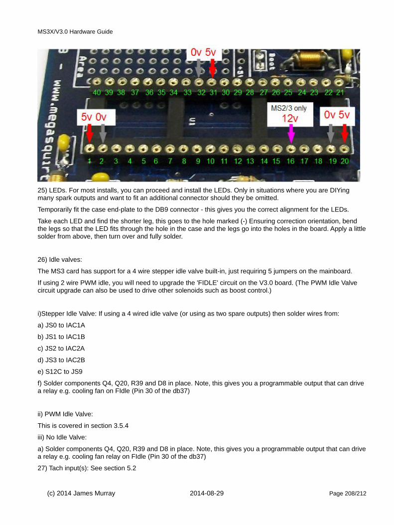
MS3X/V3.0 Hardware Guide
25) LEDs. For most installs, you can proceed and install the LEDs. Only in situations where you are DIYing many spark outputs and want to fit an additional connector should they be omitted.
Temporarily fit the case end-plate to the DB9 connector - this gives you the correct alignment for the LEDs.
Take each LED and find the shorter leg, this goes to the hole marked (-) Ensuring correction orientation, bend the legs so that the LED fits through the hole in the case and the legs go into the holes in the board. Apply a littlesolder from above, then turn over and fully solder.
26) Idle valves:
The MS3 card has support for a 4 wire stepper idle valve built-in, just requiring 5 jumpers on the mainboard.
If using 2 wire PWM idle, you will need to upgrade the 'FIDLE' circuit on the V3.0 board. (The PWM Idle Valve circuit upgrade can also be used to drive other solenoids such as boost control.)
i)Stepper Idle Valve: If using a 4 wired idle valve (or using as two spare outputs) then solder wires from:
a) JS0 to IAC1A
b) JS1 to IAC1B
c) JS2 to IAC2A
d) JS3 to IAC2B
e) S12C to JS9
f) Solder components Q4, Q20, R39 and D8 in place. Note, this gives you a programmable output that can drive a relay e.g. cooling fan on FIdle (Pin 30 of the db37)
ii) PWM Idle Valve:
This is covered in section 3.5.4
iii) No Idle Valve:
a) Solder components Q4, Q20, R39 and D8 in place. Note, this gives you a programmable output that can drivea relay e.g. cooling fan relay on FIdle (Pin 30 of the db37)
27) Tach input(s): See section 5.2
(c) 2014 James Murray 2014-08-29 Page 208/212

MS3X/V3.0 Hardware Guide
28) Spark output(s): See section 5.3
29) Next we need to check that everything is OK before we plug in the microprocessor. Plug the mainboard into your stim (or 12V supply as in step 24c) and power it up.
Ensure you have 0-5V on TSEL, if you get any more than 5V you have a wiring issue with the trigger input side which would likely destroy the MS3 CPU card. As long as you have 0-5V you can proceed to step 30.
30) Now your ready to test the board with the microprocessor in place. Fit the MS3 CPU card into socket U1. Note that it is normal for some of the pins on the large square chip on the MS3 card to appear 'bridged'.
• Noting orientation, install the MS3 card onto the mainboard (V357 shown, V3.0 works the same) noting the two 40pin socket/spacers that fit between the mainboard and the card. These ensure that the card sits at the right height to align with the end-plate.
Installing bolts
• If fitted, carefully unscrew and remove the mounting bolt and nuts from U5 and Q11. • Install the mounting kit on U5 and Q11. The long bolt and a washer install from below. The short bolt
and washer from above. Depending on the exact sizes of the components supplied in your kit, you may only install one of the standoffs.
• If required, additional washers may be installed between the standoff and the MS3 card to fine-tune the height.
Side view of completed assembly
(c) 2014 James Murray 2014-08-29 Page 209/212
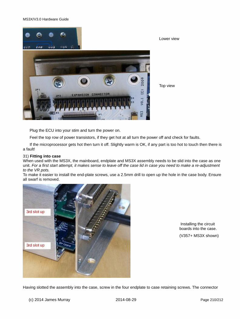
MS3X/V3.0 Hardware Guide
Lower view
Top view
Plug the ECU into your stim and turn the power on.
Feel the top row of power transistors, if they get hot at all turn the power off and check for faults.
If the microprocessor gets hot then turn it off. Slightly warm is OK, if any part is too hot to touch then there is a fault!
31) Fitting into case When used with the MS3X, the mainboard, endplate and MS3X assembly needs to be slid into the case as one unit. For a first start attempt, it makes sense to leave off the case lid in case you need to make a re-adjustment to the VR pots. To make it easier to install the end-plate screws, use a 2.5mm drill to open up the hole in the case body. Ensure all swarf is removed.
Installing the circuit boards into the case.
(V357+ MS3X shown)
Having slotted the assembly into the case, screw in the four endplate to case retaining screws. The connector
(c) 2014 James Murray 2014-08-29 Page 210/212
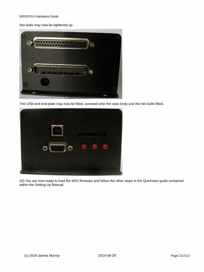
MS3X/V3.0 Hardware Guide
hex bolts may now be tightened up.
The USB end end-plate may now be fitted, screwed onto the case body and the hex bolts fitted.
32) You are now ready to load the MS3 firmware and follow the other steps in the Quickstart guide contained within the Setting Up Manual.
(c) 2014 James Murray 2014-08-29 Page 211/212

MS3X/V3.0 Hardware Guide
14: Revision history2014-08-26 First revision.
(c) 2014 James Murray 2014-08-29 Page 212/212