Ms en 1997 1 2012 Malaysia National Annex to Eurocode 7 Geotechnical Designs Part 1 General Rules...
29
MS EN 1997-1:2012 (National Annex) Malaysia National Annex to Eurocode 7: Geotechnical design - Part 1: General rules ICS: 91.010.30 Descriptors: soil mechanics, structural systems, buildings, construction engineering works, structural design, construction operations, foundations, pile foundations, retaining structures, embankments, subsoil, anchorages, mathematical calculations, design calculations, site investigations, stability © Copyright 2012 DEPARTMENT OF STANDARDS MALAYSIA MALAYSIAN STANDARD Licensed to University College of Technology Sarawak / Downloaded on : 24-Nov-2014 10:30:02 AM / Single user license only, copying and networking prohibited
-
Upload
azrul-zulwali -
Category
Documents
-
view
657 -
download
160
description
Ms en 1997 1 2012
Transcript of Ms en 1997 1 2012 Malaysia National Annex to Eurocode 7 Geotechnical Designs Part 1 General Rules...

MS EN 1997-1:2012 (National Annex)
Malaysia National Annex to Eurocode 7: Geotechnical design - Part 1: General rules ICS: 91.010.30 Descriptors: soil mechanics, structural systems, buildings, construction engineering works, structural
design, construction operations, foundations, pile foundations, retaining structures, embankments, subsoil, anchorages, mathematical calculations, design calculations, site investigations, stability
© Copyright 2012
DEPARTMENT OF STANDARDS MALAYSIA
MALAYSIAN STANDARD
Lice
nsed
to U
nive
rsity
Col
lege
of T
echn
olog
y S
araw
ak /
Dow
nloa
ded
on :
24-N
ov-2
014
10:3
0:02
AM
/ S
ingl
e us
er li
cens
e on
ly, c
opyi
ng a
nd n
etw
orki
ng p
rohi
bite
d

DEVELOPMENT OF MALAYSIAN STANDARDS
The Department of Standards Malaysia (STANDARDS MALAYSIA) is the national
standards and accreditation body of Malaysia.
The main function of STANDARDS MALAYSIA is to foster and promote standards,
standardisation and accreditation as a means of advancing the national economy,
promoting industrial efficiency and development, benefiting the health and safety of
the public, protecting the consumers, facilitating domestic and international trade
and furthering international cooperation in relation to standards and standardisation.
Malaysian Standards (MS) are developed through consensus by committees which
comprise balanced representation of producers, users, consumers and others with
relevant interests, as may be appropriate to the subject at hand. To the greatest
extent possible, Malaysian Standards are aligned to or are adoption of international
standards. Approval of a standard as a Malaysian Standard is governed by the
Standards of Malaysia Act 1996 [Act 549]. Malaysian Standards are reviewed
periodically. The use of Malaysian Standards is voluntary except in so far as they
are made mandatory by regulatory authorities by means of regulations, local by-
laws or any other similar ways.
STANDARDS MALAYSIA has appointed SIRIM Berhad as the agent to develop,
distribute and sell the Malaysian Standards.
For further information on Malaysian Standards, please contact:
Department of Standards Malaysia OR SIRIM Berhad Ministry of Science, Technology and Innovation (Company No. 367474 - V) Level 1 & 2, Block 2300, Century Square 1, Persiaran Dato’ Menteri Jalan Usahawan Section 2 63000 Cyberjaya 40000 Shah Alam Selangor Darul Ehsan Selangor Darul Ehsan MALAYSIA MALAYSIA Tel: 60 3 8318 0002 Tel: 60 3 5544 6000 Fax: 60 3 8319 3131 Fax: 60 3 5510 8095 http://www.standardsmalaysia.gov.my http://www.sirim.my E-mail: [email protected] E-mail: [email protected] Li
cens
ed to
Uni
vers
ity C
olle
ge o
f Tec
hnol
ogy
Sar
awak
/ D
ownl
oade
d on
: 24
-Nov
-201
4 10
:30:
02 A
M /
Sin
gle
user
lice
nse
only
, cop
ying
and
net
wor
king
pro
hibi
ted

MS EN 1997-1:2012
© STANDARDS MALAYSIA 2012 - All rights reserved i
CONTENTS
Page Committee representation .................................................................................................... iii Foreword.............................................................................................................................. iv NA0 Introduction...............................................................................................................1 NA1 Scope.......................................................................................................................1 NA2 Nationally determined parameters.............................................................................2 NA3 Decisions on the status of informative annexes .........................................................5 NA4 References to Non-Contradictory Complementary Information (NCCI) ......................6 NA5 Country specific data (informative) ............................................................................7 Table NA1 Provisions of this national annex related to clauses in MS EN 1997-1:2012
where "national choice" is to be exercised .......................................................2 Table NA2 Degree of decomposition of wet peat as determined by squeezing ..................7 Table A1 Partial factors on actions (F) for the equilibrium (EQU) limit state ..................10 Table A2 Partial factors for soil parameters (for the EQU limit state) .............................10 Table A3 Partial factors on actions (F) or the effects of actions (E) for the structural
(STR) and geotechnical (GEO) limit states.....................................................11 Table A4 Partial factors for soil parameters (M) for the STR and GEO limit states ........12 Table A5 Partial resistance factors (R) for spread foundations for the STR and GEO
limit states.....................................................................................................12 Table A6 Partial resistance factors (R) for driven piles for the STR and GEO limit
states ............................................................................................................13 Table A7 Partial resistance factors (R) for bored piles for the STR and GEO limit
states ............................................................................................................14 Table A8 Partial resistance factors (R) for continuous flight auger CFA piles for the
STR and GEO limit states..............................................................................14
Lice
nsed
to U
nive
rsity
Col
lege
of T
echn
olog
y S
araw
ak /
Dow
nloa
ded
on :
24-N
ov-2
014
10:3
0:02
AM
/ S
ingl
e us
er li
cens
e on
ly, c
opyi
ng a
nd n
etw
orki
ng p
rohi
bite
d

MS EN 1997-1:2012
ii © STANDARDS MALAYSIA 2012 - All rights reserved
CONTENTS (continued)
Page Table A9 Correlation factors (ξ) to derive characteristic values of the resistance of
axially loaded piles from static pile load tests (n-number of tested piles).........15 Table A10 Correlation factors (ξ) to derive characteristic values of the resistance of
axially loaded piles from ground test results (n-number of profiles of tests).....15 Table A11 Correlation factors (ξ) to derive characteristic values of the resistance of
axially loaded piles from dynamic impact tests (where n is the number of tested piles)...................................................................................................16
Table A12 Partial resistance factors (R) for pre-stressed anchorages at the STR and
GEO limit states ............................................................................................16 Table A13 Partial resistance factors (R) for retaining structures at the STR and GEO
limit states.....................................................................................................16 Table A14 Partial resistance factors (R) for slopes and overall stability at the STR and
GEO limit states ............................................................................................17 Table A15 Partial factors on actions (F) at the UPL limit state ........................................17 Table A16 Partial factors for soil parameters (M) and resistance (R) at the UPL limit
state..............................................................................................................18 Table A17 Partial factors on actions (F) at the Hydraulic Heave (HYD) limit state...........18 Annex A Design approach and values of partial, correlation and model factors for
ultimate limit states to be used in conjunction with MS EN 1997-1:2012...........9 Bibliography ........................................................................................................................20
Lice
nsed
to U
nive
rsity
Col
lege
of T
echn
olog
y S
araw
ak /
Dow
nloa
ded
on :
24-N
ov-2
014
10:3
0:02
AM
/ S
ingl
e us
er li
cens
e on
ly, c
opyi
ng a
nd n
etw
orki
ng p
rohi
bite
d
MS EN 1997-1:2012
© STANDARDS MALAYSIA 2012 - All rights reserved iii
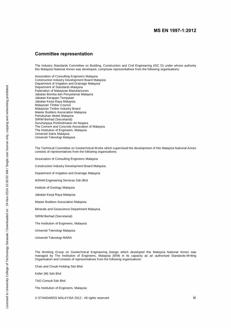
Committee representation The Industry Standards Committee on Building, Construction and Civil Engineering (ISC D) under whose authority this Malaysia National Annex was developed, comprises representatives from the following organisations: Association of Consulting Engineers Malaysia Construction Industry Development Board Malaysia Department of Irrigation and Drainage Malaysia Department of Standards Malaysia Federation of Malaysian Manufacturers Jabatan Bomba dan Penyelamat Malaysia Jabatan Kerajaan Tempatan Jabatan Kerja Raya Malaysia Malaysian Timber Council Malaysian Timber Industry Board Master Builders Association Malaysia Pertubuhan Akitek Malaysia SIRIM Berhad (Secretariat) Suruhanjaya Perkhidmatan Air Negara The Cement and Concrete Association of Malaysia The Institution of Engineers, Malaysia Universiti Sains Malaysia Universiti Teknologi Malaysia The Technical Committee on Geotechnical Works which supervised the development of this Malaysia National Annex consists of representatives from the following organisations: Association of Consulting Engineers Malaysia Construction Industry Development Board Malaysia Department of Irrigation and Drainage Malaysia IKRAM Engineering Services Sdn Bhd Institute of Geology Malaysia Jabatan Kerja Raya Malaysia Master Builders Association Malaysia Minerals and Geoscience Department Malaysia SIRIM Berhad (Secretariat) The Institution of Engineers, Malaysia Universiti Teknologi Malaysia Universiti Teknologi MARA The Working Group on Geotechnical Engineering Design which developed this Malaysia National Annex was managed by The Institution of Engineers, Malaysia (IEM) in its capacity as an authorised Standards-Writing Organisation and consists of representatives from the following organisations: Chan and Chuah Holding Sdn Bhd Keller (M) Sdn Bhd TAO Consult Sdn Bhd The Institution of Engineers, Malaysia
Lice
nsed
to U
nive
rsity
Col
lege
of T
echn
olog
y S
araw
ak /
Dow
nloa
ded
on :
24-N
ov-2
014
10:3
0:02
AM
/ S
ingl
e us
er li
cens
e on
ly, c
opyi
ng a
nd n
etw
orki
ng p
rohi
bite
d

MS EN 1997-1:2012
iv © STANDARDS MALAYSIA 2012 - All rights reserved
FOREWORD The Malaysia National Annex was developed by the Working Group on Geotechnical Engineering Design under the authority of the Industry Standards Committee on Building, Construction and Civil Engineering. Development of this national annex was carried out by The Institution of Engineers, Malaysia which is the Standards-Writing Organisation (SWO) appointed by SIRIM Berhad to develop standards for geotechnical works. This Malaysia National Annex shall be used together with MS EN 1997-1:2012, Eurocode 7: Geotechnical design - Part 1: General rules. Acknowledgement is given to BSI for the use of information from UK National Annex to Eurocode 7: Geotechnical design - Part 1: General rules. Compliance with a Malaysian Standard does not of itself confer immunity from legal obligations.
Lice
nsed
to U
nive
rsity
Col
lege
of T
echn
olog
y S
araw
ak /
Dow
nloa
ded
on :
24-N
ov-2
014
10:3
0:02
AM
/ S
ingl
e us
er li
cens
e on
ly, c
opyi
ng a
nd n
etw
orki
ng p
rohi
bite
d

MS EN 1997-1:2012
© STANDARDS MALAYSIA 2012 - All rights reserved 1
MALAYSIA NATIONAL ANNEX TO MS EN 1997-1:2012, EUROCODE 7: GEOTECHNICAL DESIGN - PART 1: GENERAL RULES
NA0 Introduction This national annex has been prepared by Working Group on Geotechnical Engineering Design. In Malaysia, it shall be used in conjunction with MS EN 1997-1:2012, Eurocode 7: Geotechnical design - Part 1: General rules and MS EN 1990:2010, Eurocode - Basis of structural design. NA1 Scope This national annex gives: a) the Malaysia decisions for the nationally determined parameters (See NA2) described in
the following subclauses in the body of MS EN 1997-1:2012:
2.1(8)P 2.4.7.4(3)P 7.6.2.4(4)P
2.4.6.1(4)P 2.4.7.5(2)P 7.6.3.2(2)P
2.4.6.2(2)P 2.4.8(2) 7.6.3.2(5)P
2.4.7.1(2)P 2.4.9(1)P 7.6.3.3(3)P
2.4.7.1(3) 2.5(1) 7.6.3.3(4)P
2.4.7.2(2)P 7.6.2.2(8)P 7.6.3.3(6)
2.4.7.3.2(3)P 7.6.2.2(14)P 8.5.2(2)P
2.4.7.3.3(2)P 7.6.2.3(4)P 8.5.2(3)
2.4.7.3.4.1(1)P 7.6.2.3(5)P 8.6(4)
7.6.2.3(8) 11.5.1(1)P
and the following subclauses in Annex A of MS EN 1997-1:2012: - A.2 - A.3.1, A.3.2, A.3.3.1, A.3.3.2, A.3.3.3, A.3.3.4, A.3.3.5, A.3.3.6 - A.4 - A.5; b) the procedure to be used where alternative procedures are given in MS EN 1997-1:2012
(see NA2 first paragraph); c) the Malaysia’s decisions on the status of MS EN 1997-1:2012 informative annexes (see
NA3); d) references to non-contradictory complementary information (see NA4); and e) country specific data.
Lice
nsed
to U
nive
rsity
Col
lege
of T
echn
olog
y S
araw
ak /
Dow
nloa
ded
on :
24-N
ov-2
014
10:3
0:02
AM
/ S
ingl
e us
er li
cens
e on
ly, c
opyi
ng a
nd n
etw
orki
ng p
rohi
bite
d

MS EN 1997-1:2012
2 © STANDARDS MALAYSIA 2012 - All rights reserved
NA2 Nationally determined parameters National choice is permitted in the use of a Design Approach for the STR and GEO limit states (see MS EN 1997-1:2012, 2.4.7.3.4.1(1)P). As indicated in Table NA1, only Design Approach 1 is to be used in Malaysia. Annex A of MS EN 1997-1:2012 lists the partial and correlation factors for ultimate limit states; the values of these factors are nationally determined parameters. Table NA1 of this national annex lists the clauses in MS EN 1997-1:2012 where national choice may be exercised in respect of factor values for design in Malaysia. Where choice applies, Table NA1 indicates where values are given, or states a value to be used, or describes the procedure for specifying the factor. The values given in the Tables in Annex A of this national annex replace the recommended values in Annex A of MS EN 1997-1:2012. Where reference is made in MS EN 1997-1:2012 to the use of Annex A as a guide to the required levels of safety, this reference should be taken to mean Annex A of this national annex. MS EN 1997-1:2012 contains several references to "model factors" without making recommendations for the values to be used. Table NA1 of this national annex also lists these references. In some cases, values of the model factors are given in A6 of Annex A of this national annex. Where no values are given, the values should be agreed, where appropriate, with the client and the relevant authorities. Subclauses 2.4.1(8) and 2.4.1(9) in MS EN 1997-1:2012 give guidance on how the values of such model factors should be selected. Model factors for pile design are given in A3.3.2 of Annex A of this national annex.
Table NA1. Provisions of this national annex related to clauses in MS EN 1997-1:2012 where "national choice" is to be exercised
Subclause Feature Provisions of this national annex
2.1(8)P Minimum requirements for light and simple structures and small earthworks.
Minimum requirements are not given in this national annex and should be agreed where appropriate with the client and relevant authorities.
2.4.6.1(4)P The value of partial factor F for persistent and transient situations.
Use the values given in A2.1 (EQU); A3.1 (STR/GEO); A4.1 (UPL) and A5 (HYD) in Annex A of this national annex.
2.4.6.1(5) Directly assessed design values for actions.
Where design values of actions are assessed directly the values of the partial factors for actions given in Annex A of this national annex should be used as a guide to the required level of safety.
2.4.6.2(2)P The value of partial factor M for persistent and transient situations.
Use the values given in A2.2 (EQU); A3.2 (STR/GEO) and A4.2 (UPL) in Annex A of this national annex.
2.4.6.2(3) Directly assessed design values for geotechnical parameters.
Where design values of soil parameters are assessed directly, the values of the partial factors for soil parameters given in Annex A of this national annex should be used as a guide to the required level of safety.
Lice
nsed
to U
nive
rsity
Col
lege
of T
echn
olog
y S
araw
ak /
Dow
nloa
ded
on :
24-N
ov-2
014
10:3
0:02
AM
/ S
ingl
e us
er li
cens
e on
ly, c
opyi
ng a
nd n
etw
orki
ng p
rohi
bite
d

MS EN 1997-1:2012
© STANDARDS MALAYSIA 2012 - All rights reserved 3
Table NA1. Provisions of this national annex related to clauses in MS EN 1997-1:2012 where "national choice" is to be exercised (continued)
Subclause Feature Provisions of this national annex
2.4.7.1(2)P The values of partial factors to be used in persistent and transient situations.
Use the values given in the appropriate tables in Annex A of this national annex.
2.4.7.1(3) The value of partial factors to be used in accidental situations.
Take as equal to 1.0.
2.4.7.1(3) The values of partial factors for resistance.
Use the values given in the appropriate tables in Annex A of this national annex.
2.4.7.1(4) The values of partial factors to be used in cases of abnormal risk or unusual or exceptionally difficult ground or loading conditions.
Values are not provided in this national annex and should be agreed with the client and relevant authorities, where appropriate, for the specific situation.
2.4.7.1(5) Reduced values of partial factors to be used for special situations for temporary structures or transient design situations, where the likely consequences justify it.
Values are not provided in this national annex and might need to be agreed with the client and relevant authorities, for the specific situation.
2.4.7.1(6) Values for model factors for resistance and the effects of actions.
See A6.1 to A6.5 of Annex A of this national annex.
2.4.7.2(2)P The values of partial factors to be used in persistent and transient situations for the EQU limit state.
Use the values given in A2 in Annex A of national annex.
2.4.7.3.2(3)P The values of partial factors to be used in equations (2.6a) and (2.6b) of MS EN 1997-1:2012 for determining the design effects for STR and GEO limit states.
Use the values given in A3 in Annex A of this national annex.
2.4.7.3.3(2)P The values of partial factors to be used in equations (2.7a), (2.7b) and (2.7c) of MS EN 1997-1:2012 for determining the design resistances in the STR and GEO limit states.
Use the values given in A3.3.1, A3.3.2, A3.3.3, A3.3.4, A3.3.5 and A3.3.6 in Annex A of this national annex.
2.4.7.3.4.1(1)P The particular Design Approach to be used for the STR and GEO limit states.
Use Design Approach 1 only.
2.4.7.4(3)P The values of partial factors for persistent and transient situations for the UPL limit state.
Use the values given in A4 in Annex A of this national annex.
2.4.7.5(2)P The values of partial factors for persistent and transient situations for the HYD limit state.
Use the values given in A5 in Annex A of this national annex.
2.4.8(2) The values of partial factors for serviceability limit state.
Take as equal to 1.0.
2.4.9(1)P The amounts of permitted foundation movement.
Values are not provided in this national annex. Advice is given on foundation movements for buildings in Annex H of MS EN 1997-1:2012.
2.5(1) Conventional and generally conservative rules.
The use of prescriptive measures for design should be agreed, where appropriate, with the client and the relevant authorities. (see 2.1(8) above).
7.6.2.2(8)P The values of correlation factors ξ1 and ξ2.
Use the values given in A3.3.3 of Annex A of this national annex.
Lice
nsed
to U
nive
rsity
Col
lege
of T
echn
olog
y S
araw
ak /
Dow
nloa
ded
on :
24-N
ov-2
014
10:3
0:02
AM
/ S
ingl
e us
er li
cens
e on
ly, c
opyi
ng a
nd n
etw
orki
ng p
rohi
bite
d
MS EN 1997-1:2012
4 © STANDARDS MALAYSIA 2012 - All rights reserved
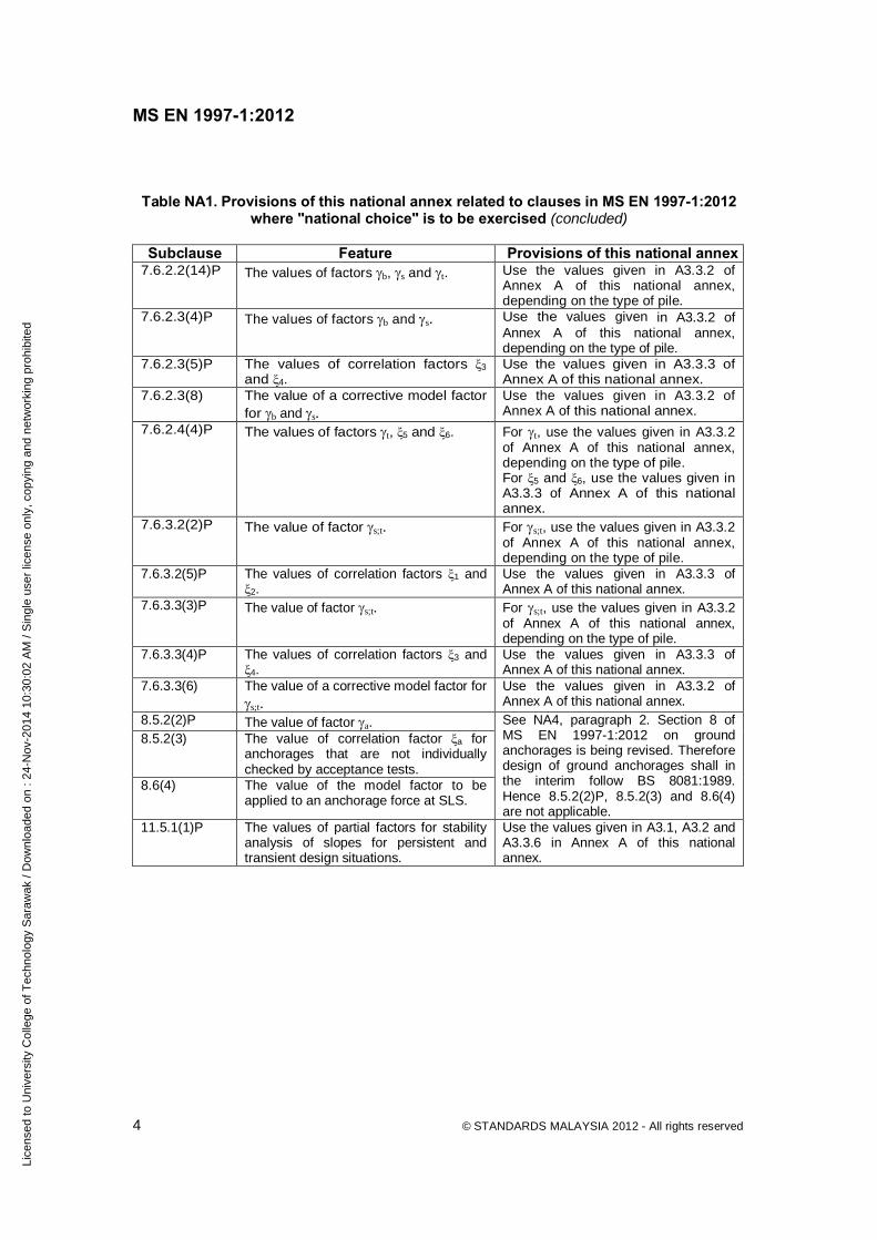
Table NA1. Provisions of this national annex related to clauses in MS EN 1997-1:2012 where "national choice" is to be exercised (concluded)
Subclause Feature Provisions of this national annex
7.6.2.2(14)P The values of factors b, s and t. Use the values given in A3.3.2 of Annex A of this national annex, depending on the type of pile.
7.6.2.3(4)P The values of factors b and s. Use the values given in A3.3.2 of Annex A of this national annex, depending on the type of pile.
7.6.2.3(5)P The values of correlation factors ξ3 and ξ4.
Use the values given in A3.3.3 of Annex A of this national annex.
7.6.2.3(8) The value of a corrective model factor for b and s.
Use the values given in A3.3.2 of Annex A of this national annex.
7.6.2.4(4)P The values of factors t, ξ5 and ξ6. For t, use the values given in A3.3.2 of Annex A of this national annex, depending on the type of pile. For ξ5 and ξ6, use the values given in A3.3.3 of Annex A of this national annex.
7.6.3.2(2)P The value of factor s;t. For s;t, use the values given in A3.3.2 of Annex A of this national annex, depending on the type of pile.
7.6.3.2(5)P The values of correlation factors ξ1 and ξ2.
Use the values given in A3.3.3 of Annex A of this national annex.
7.6.3.3(3)P The value of factor s;t. For s;t, use the values given in A3.3.2 of Annex A of this national annex, depending on the type of pile.
7.6.3.3(4)P The values of correlation factors ξ3 and ξ4.
Use the values given in A3.3.3 of Annex A of this national annex.
7.6.3.3(6) The value of a corrective model factor for s;t.
Use the values given in A3.3.2 of Annex A of this national annex.
8.5.2(2)P The value of factor a. 8.5.2(3) The value of correlation factor ξa for
anchorages that are not individually checked by acceptance tests.
8.6(4) The value of the model factor to be applied to an anchorage force at SLS.
See NA4, paragraph 2. Section 8 of MS EN 1997-1:2012 on ground anchorages is being revised. Therefore design of ground anchorages shall in the interim follow BS 8081:1989. Hence 8.5.2(2)P, 8.5.2(3) and 8.6(4) are not applicable.
11.5.1(1)P The values of partial factors for stability analysis of slopes for persistent and transient design situations.
Use the values given in A3.1, A3.2 and A3.3.6 in Annex A of this national annex.
Lice
nsed
to U
nive
rsity
Col
lege
of T
echn
olog
y S
araw
ak /
Dow
nloa
ded
on :
24-N
ov-2
014
10:3
0:02
AM
/ S
ingl
e us
er li
cens
e on
ly, c
opyi
ng a
nd n
etw
orki
ng p
rohi
bite
d

MS EN 1997-1:2012
© STANDARDS MALAYSIA 2012 - All rights reserved 5
NA3 Decisions on the status of informative annexes NA3.1 Annex B MS EN 1997-1:2012, Annex B may be used. MS EN 1997-1:2012, B.1(3), B.1(4) and B.1(5) and B.2(6) and B.2(7) relate to Design Approach 2 and 3 and are therefore not applicable to designs in Malaysia. NOTE. Design resistances are expressed in three forms in MS EN 1997-1: 2012, 2.4.7.3.3, namely Equations (2.7a), (2.7b) and (2.7c). Equations (2.7a) and (2.7b) are simplifications of Equation (2.7c) for the specific cases where M =1 and R =1, respectively. The reference to Equation (2.7) in B.3(1) is strictly relevant to Equation (2.7c). NA3.2 Annex C MS EN 1997-1:2012, Annex C may be used. The values of Ka and Kp given in Figures C.1.1 to C.1.4 and Figures C.2.1 to C.2.4 relate to vertical retained faces. Where the retained face is inclined, Equations (C.6) and (C.9) should be used. The note under Equation (C.9) says the expression is on the safe side; this can be taken to mean that it over-estimates the active pressure and under-estimate the passive pressure. When the active pressure is favourable and passive pressure is unfavourable the results are therefore not on the safe side. The values of Ka and Kp given in Figures C.1.1 to C.1.4 and Figures C.2.1 to C.2.4 are based on different theories from those on which Equations (C.6) and (C.9) are based. The two methods will therefore yield different results when δ is not equal to zero. The equations are more soundly based in theory but there is long experience of use of the graphs (i.e. Figures C.1.1 to C.1.4 and Figures C.2.1 to C.2.4). They differ mainly for high values of φ’ and δ/φ’ for which it might be difficult to establish the reliability of the experience. NA3.3 Annex D Annex D may be used with the following modifications: a) The factor N in Equation (D.2) should be determined by the following equation which
supersedes the formula for N given in the Annex D: N = (Nq-1) tan (1.4φ’) b) The sample method given in MS EN 1997-1:2012, Annex D omits depth and ground
inclination factors which are commonly found in bearing resistance formulations. The omission of the depth factor errs on the side of safety, but the omission of the ground inclination factor does not. To determine the ground inclination factor, one of the methods which may be considered is described in Foundations and Earth Structures Design Manual[23].
Lice
nsed
to U
nive
rsity
Col
lege
of T
echn
olog
y S
araw
ak /
Dow
nloa
ded
on :
24-N
ov-2
014
10:3
0:02
AM
/ S
ingl
e us
er li
cens
e on
ly, c
opyi
ng a
nd n
etw
orki
ng p
rohi
bite
d

MS EN 1997-1:2012
6 © STANDARDS MALAYSIA 2012 - All rights reserved
NA3.4 Annex H MS EN 1997-1:2012, Annex H may be used. NOTE. The limiting values of structural deformation and foundation movement relate primarily to buildings. Limiting value of structural deformation and foundation movement for other civil engineering works should be determined for the project and agreed, where appropriate, with the client and relevant authorities. NA3.5 Other annexes MS EN 1997-1:2012, Annex E, Annex F, Annex G and Annex J may be used. NA4 References to Non-Contradictory Complementary Information (NCCI) The following is a list of references that contain Non-Contradictory Complementary Information (NCCI) for use with MS EN 1997-1:2012. MS 1056 (all parts), Soils for civil engineering purposes - Test method; MS 1754, Earthworks - Code of practice; MS 1756, Foundations - Code of practice; BS 1377 (all parts), Methods of test for soils for civil engineering purposes; BS 5930, Code of practice for site investigations; BS 6031, Code of practice for earthworks; BS 8002, Code of practice for earth retaining structures; BS 8004, Code of practice for foundations; BS 8008, Safety precautions and procedures for the construction and descent of machine-bored shafts for piling and other purposes; BS 8081, Code of practice for ground anchorages; PD 6694-1, Recommendations for the design of structures subject to traffic loading to BS EN 1997-1; CIRIA C580, Embedded retaining walls - guidance for economic design[24]; UK Design Manual for Roads and Bridges[29]; ISO 14688-1:2002, Geotechnical investigation and testing - Identification and classification of soil - Part 1:Identification and description; ISO 14688-2:2004, Geotechnical investigation and testing - Identification and classification of soil - Part 2:Principles for a classification. Design aspects of some of these, or parts of them, might be in conflict with the design principles in the MS EN 1997-1:2012. Until such time as "residual" documents are prepared to remove such conflicts and in the event that use of these documents presents a conflict, the Eurocode takes precedence other than design of ground anchorages. Section 8 of MS EN 1997-1:2012 on ground anchorages is being revised and EN 1537 (execution standard of ground anchors) is under major revision in the design and testing sections of the execution standard. Until the revisions are completed and the revised documents published, design and testing of ground anchorages shall follow relevant parts of BS 8081, and execution of ground anchorages shall follow the execution sections of EN 1537. MS EN 1997-1:2012, Geotechnical design does not cover the design and execution of reinforced soil structures. The design and execution of reinforced fill structures and soil nailing should be carried out in accordance with BS 8006, BS EN 14475 and BS EN 14490. The partial factors set out in BS 8006 should not be replaced by similar factors from MS EN 1997-1:2012 or this national annex.
Lice
nsed
to U
nive
rsity
Col
lege
of T
echn
olog
y S
araw
ak /
Dow
nloa
ded
on :
24-N
ov-2
014
10:3
0:02
AM
/ S
ingl
e us
er li
cens
e on
ly, c
opyi
ng a
nd n
etw
orki
ng p
rohi
bite
d

MS EN 1997-1:2012
© STANDARDS MALAYSIA 2012 - All rights reserved 7
NA5 Country specific data (informative) NA5.1 Foundations in limestone areas Ground conditions in limestone areas are considered as exceptionally difficult. Relevant local publications should be referred on this subject[21]. Foundation design in limestone areas shall be classified as Geotechnical Category 3 in accordance with Clause 2.1(8)P. The requirements described in MS EN 1997-1:2012 are minimum. The extent and content of geotechnical investigations may need to be expanded, design control and construction control shall be stringent. The amount of investigations required will be at least the same as indicated for Geotechnical Category 2 projects described in BS EN 1997-2. Additional investigations and more specialised tests may be necessary; for example, because of karstic features of limestone formations and possible presence of pinnacles and cavities, the recommendations on spacing and depth of investigations in Annex B.3 of BS EN 1997-2 need to be modified. Design supervision level (DSL) shall be DSL3 described in Table B4 of MS EN 1990:2010. Inspection level shall be IL3 described in Table B5 of MS EN 1990:2010. Additional requirements are described in Section 4 of MS EN 1997-1:2012. NA5.2 Geotechnical works in peat Peat is identified by its dark colour, characteristic mouldy odour and presence of plant remains. Peat is classified as fibrous peat, pseudo-fibrous peat or amorphous peat according to the degree of decomposition. The degree of decomposition can be established by squeezing a wet sample. Refer Table 5 of ISO 14688-1:2002. The table is reproduced below for ease of reference.
Table NA2. Degree of decomposition of wet peat as determined by squeezing
Term Decomposition Remains Squeeze Fibrous Not Clearly
recognisable Only water No solids
Pseudo-fibrous Moderate Recognisable Turbid water <50% solids
Amorphous Full Not recognisable
Paste >50% solids
Description of the genesis and characteristics of peat in Malaysia can be found in some local publications[25][26]. It should be noted that peat in Malaysia is a tropical peat and some of its properties are different from those of the peat found in the temperate countries, for example the rate of land subsidence in a developed peat area. Therefore, drainage management may need to be included as part of the design.
Lice
nsed
to U
nive
rsity
Col
lege
of T
echn
olog
y S
araw
ak /
Dow
nloa
ded
on :
24-N
ov-2
014
10:3
0:02
AM
/ S
ingl
e us
er li
cens
e on
ly, c
opyi
ng a
nd n
etw
orki
ng p
rohi
bite
d

MS EN 1997-1:2012
8 © STANDARDS MALAYSIA 2012 - All rights reserved
Engineering properties of fibrous peat are significantly different from most of inorganic soils; for example the almost indefinite prolonged post-construction settlement with time[27].Therefore, design of structures in peat would include considerations of factors which are not necessary or crucial for a similar design in inorganic soils. NA5.3 Partially saturated fill Collapse compression of a partially saturated fill could result in large post-construction settlement or ground movement. The problem is associated with the movement of groundwater or the ingress of surface water. It is a major hazard for buildings on fill. As collapse compression can occur unpredictably many years after embankment construction and may be localised, this form of settlement is also hazardous to road pavement. The potential for collapse compression is linked to the uncompacted state of the fill with air voids being a key parameter. In Malaysia, such problems have been encountered, for example, in large post-construction settlement of deep fill subjected to ingress of water. Therefore, in designing embankment or structures on deep fill, effects of post-construction ground movement due to long term wetting of the fill should be considered[22].
Lice
nsed
to U
nive
rsity
Col
lege
of T
echn
olog
y S
araw
ak /
Dow
nloa
ded
on :
24-N
ov-2
014
10:3
0:02
AM
/ S
ingl
e us
er li
cens
e on
ly, c
opyi
ng a
nd n
etw
orki
ng p
rohi
bite
d

MS EN 1997-1:2012
© STANDARDS MALAYSIA 2012 - All rights reserved 9
Annex A (normative)
Design approach and values of partial, correlation and model factors for ultimate limit states to be used in conjunction with MS EN 1997-1:2012
A1 Nationally determined parameters A1.1 This annex gives: a) partial factors for geotechnical actions (F) or the effects of geotechnical actions (E) for
ultimate limit states in the persistent and transient design situations;
b) partial factors for soil properties (M) for ultimate limit states in the persistent and transient design situations;
c) partial factors for resistances (R) for ultimate limit states in the persistent and transient
design situations; d) correlation factors (ξ) for pile foundations and anchorages in all design situations; and e) advice on the use of model factors. A1.2 As stated in NA2, paragraph 1, only Design Approach 1 is used in Malaysia for the STR and GEO limit states. This annex therefore only provides partial factors appropriate for Design Approach 1. In applying Design Approach 1, the design resistance for both Combination 1 and Combination 2 can be found using Equation (2.7c) in MS EN 1997-1:2012. Equations (2.7a) and (2.7b) are simplified versions of Equation (2.7c) which can be used in situations where R =1 and M =1, respectively. For sliding, Equations (6.3a) and/or (6.4a) in MS EN 1997-1:2012 can be used for both Combination 1 and Combination 2. Equations (6.3a) and (6.4a) are simplified versions of the full expressions for sliding resistance for situations where R;h =1. The partial factors specified for permanent actions in this annex have been established to be consistent with the principle that a single partial factor can be applied to permanent actions arising from a single source for the STR and GEO limit states (see note to 2.4.2(9)P of MS EN 1997-1:2012). A2 Partial factors for the equilibrium limit state (EQU) verification A2.1 Partial factors on actions (F) For the verification of the equilibrium limit state (EQU), the values of the partial factors on actions are given in Table A1. In cases where overturning instability of a structure could occur without the resistance of the ground being exceeded the partial factors specified in the national annex to MS EN 1990:2010 can give an overall factor of safety on overturning lower than that from which confidence has been gained through past Malaysia practice. In such cases, it is recommended that consideration be given to the use of higher partial factors.
Lice
nsed
to U
nive
rsity
Col
lege
of T
echn
olog
y S
araw
ak /
Dow
nloa
ded
on :
24-N
ov-2
014
10:3
0:02
AM
/ S
ingl
e us
er li
cens
e on
ly, c
opyi
ng a
nd n
etw
orki
ng p
rohi
bite
d
MS EN 1997-1:2012
10 © STANDARDS MALAYSIA 2012 - All rights reserved
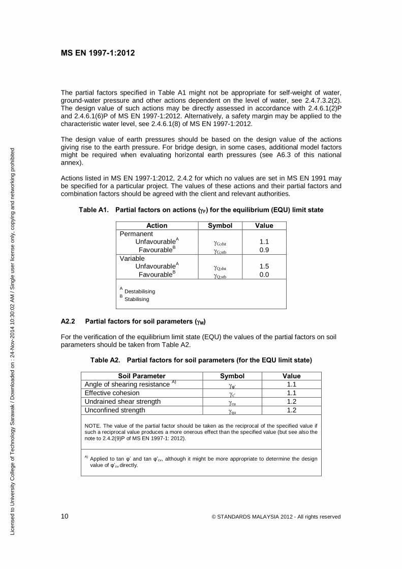
The partial factors specified in Table A1 might not be appropriate for self-weight of water, ground-water pressure and other actions dependent on the level of water, see 2.4.7.3.2(2). The design value of such actions may be directly assessed in accordance with 2.4.6.1(2)P and 2.4.6.1(6)P of MS EN 1997-1:2012. Alternatively, a safety margin may be applied to the characteristic water level, see 2.4.6.1(8) of MS EN 1997-1:2012. The design value of earth pressures should be based on the design value of the actions giving rise to the earth pressure. For bridge design, in some cases, additional model factors might be required when evaluating horizontal earth pressures (see A6.3 of this national annex). Actions listed in MS EN 1997-1:2012, 2.4.2 for which no values are set in MS EN 1991 may be specified for a particular project. The values of these actions and their partial factors and combination factors should be agreed with the client and relevant authorities.
Table A1. Partial factors on actions (F) for the equilibrium (EQU) limit state
Action Symbol Value Permanent
UnfavourableA G;dst 1.1 FavourableB G;stb 0.9
Variable UnfavourableA Q;dst 1.5 FavourableB Q;stb 0.0
A Destabilising B Stabilising
A2.2 Partial factors for soil parameters (M) For the verification of the equilibrium limit state (EQU) the values of the partial factors on soil parameters should be taken from Table A2.
Table A2. Partial factors for soil parameters (for the EQU limit state)
Soil Parameter Symbol Value Angle of shearing resistance A) φ’ 1.1 Effective cohesion c’ 1.1 Undrained shear strength cu 1.2 Unconfined strength qu 1.2
NOTE. The value of the partial factor should be taken as the reciprocal of the specified value if such a reciprocal value produces a more onerous effect than the specified value (but see also the note to 2.4.2(9)P of MS EN 1997-1: 2012).
A) Applied to tan φ’ and tan φ’cv, although it might be more appropriate to determine the design value of φ’cv directly.
Lice
nsed
to U
nive
rsity
Col
lege
of T
echn
olog
y S
araw
ak /
Dow
nloa
ded
on :
24-N
ov-2
014
10:3
0:02
AM
/ S
ingl
e us
er li
cens
e on
ly, c
opyi
ng a
nd n
etw
orki
ng p
rohi
bite
d

MS EN 1997-1:2012
© STANDARDS MALAYSIA 2012 - All rights reserved 11
A3 Partial factors for structural (STR) and geotechnical (GEO) limit states verification A3.1 Partial factors on actions (F) or the effects of actions (E) Table A3. Partial factors on actions (F) or the effects of actions (E) for the structural
(STR) and geotechnical (GEO) limit states
Set Action Symbol A1 A2 Unfavourable 1.35 1.0 Permanent Favourable G 1.0 1.0 Unfavourable 1.5 1.3 Variable Favourable Q 0.0 0.0
For the verification of the structural (STR) and geotechnical (GEO) limit states, the values of the partial factors on actions (F) or the effects of actions (E) should be taken from Table A3. The partial factors values specified in Table A3 might not be appropriate for self-weight of water, ground-water pressure and other actions dependent on the level of water, see 2.4.7.3.2(2). The design value of such actions maybe directly assessed in accordance with 2.4.6.1(2)P and 2.4.6.1(6)P of MS EN 1997-1:2012. Alternatively, a safety margin may be applied to the characteristic water level, see 2.4.6.1(8) of MS EN 1997-1:2012. The design value of earth pressures should be based on the design value of the actions giving rise to the earth pressure. For bridge design, in some cases, additional model factors might be required when evaluating horizontal earth pressures, see A6.3 of this national annex. Actions listed in 2.4.2 of MS EN 1997-1:2012 for which no values are set in MS EN 1991:2010 may be specified for a particular project. The values of these actions and their partial factors and combination factors might need to be agreed with the client and relevant authorities. A3.2 Partial factors for soil parameters (M) For the verification of the structural (STR) and geotechnical (GEO) limit states, the values of the partial factors on soil parameters should be taken from Table A4.
Lice
nsed
to U
nive
rsity
Col
lege
of T
echn
olog
y S
araw
ak /
Dow
nloa
ded
on :
24-N
ov-2
014
10:3
0:02
AM
/ S
ingl
e us
er li
cens
e on
ly, c
opyi
ng a
nd n
etw
orki
ng p
rohi
bite
d

MS EN 1997-1:2012
12 © STANDARDS MALAYSIA 2012 - All rights reserved
Table A4. Partial factors for soil parameters (M) for the STR and GEO limit states
Set Soil parameter Symbol M1 M2
(Other than slopes and
embankments)
M2 (Slopes and
embankments)
Angle of shearing resistance A) φ’ 1.0 1.25 1.35B) Effective cohesion c’ 1.0 1.25 1.35B)
Undrained shear strength cu 1.0 1.40 1.50B) Unconfined strength qu 1.0 1.40 1.50B)
NOTE. The value of the partial factor should be taken as the reciprocal of the specified value if such a reciprocal value produces a more onerous effect than the specified value (but see also the note to 2.4.2(9)P in MS EN 1997-1: 2012.
A) Applied to tan φ’ and tan φ’cv although it might be more appropriate to determine the design value of φ’cv directly. B) Less severe M value may be used for temporary structures or transient design situations (for example, end of construction stability for embankment) where the likely consequences justify it. Variation of these factors is permitted in particular, circumstances when justified by thorough consideration and documented experience, and after being agreed, where appropriate, with the relevant authorities.
A3.3 Partial resistance factors (R) A3.3.1 Partial resistance factors for spread foundations For the verifications of the structural (STR) and geotechnical (GEO) limit states the values of the partial factors R;v on bearing resistance and R;h on sliding resistance should be as given in Table A5. Table A5. Partial resistance factors (R) for spread foundations for the STR and GEO
limit states
Resistance Symbol Set R1
Bearing R;v 1.0
Sliding R;h 1.0
A3.3.2 Partial resistance factors for pile foundations The values of factors provided here are considered to be generally applicable for pile foundations. However, variation of these factors is permitted in particular circumstances when justified by thorough consideration and documented experience, and after being agreed, where appropriate, with the relevant authorities.
Lice
nsed
to U
nive
rsity
Col
lege
of T
echn
olog
y S
araw
ak /
Dow
nloa
ded
on :
24-N
ov-2
014
10:3
0:02
AM
/ S
ingl
e us
er li
cens
e on
ly, c
opyi
ng a
nd n
etw
orki
ng p
rohi
bite
d

MS EN 1997-1:2012
© STANDARDS MALAYSIA 2012 - All rights reserved 13
For verifications of the structural (STR) and geotechnical (GEO) limit states of pile foundations, the values of the partial factors on resistance (R) should be those given in Table A6, Table A7 and Table A8. These values are used to convert characteristic resistances to design values for ultimate limit state calculations. They apply irrespective of the process by which the characteristic resistances are derived. Jack-in piles are classified as driven piles. Table A6 applies also to jack-in piles. Characteristic resistances may be derived from static load tests using MS EN 1997-1:2012, 7.6.2.2 (7.6.3.2 for tensile loading), or from ground test results using MS EN 1997-1:2012, Equations (7.8) or (7.9) ((7.17) or (7.18) for tensile loading). When the approach of Equations (7.9) or (7.18) is used to derive the characteristic resistances, a model factor should be applied to the shaft and base resistance calculated using characteristic values of soil properties by a method complying with MS EN 1997-1:2012, 2.4.1(6). The value of the model factor should be 1.4, except that it may be reduced to 1.2 if the resistance is verified by a maintained load test taken to the calculated, unfactored ultimate resistance. The trial pile static load test should meet the requirements spelt out in 7.5.1 and 7.5.2 of MS EN 1997-1:2012. The required number of trial piles shall comply with 7.5.2.2 of MS EN 1997-1:2012. ICE Specification[28] can be used in determining the appropriate level of pile testing.
Table A6. Partial resistance factors (R) for driven piles for the STR and GEO limit states
Set
Resistance Symbol R1 R4 without
explicit verification of
SLSA)
R4 with explicit verification of
SLSA)
Base b 1.0 1.87 1.65 Shaft (compression) s 1.0 1.65 1.43
Total/combined (compression)
t 1.0 1.87 1.65
Shaft in tension s;t 1.0 2.20 1.87 A) The lower R values in R4 may be adopted
a) if serviceability is verified by static load tests (preliminary and/or working) carried out on more than 1% of the constructed piles to loads not less than 1.5 times the representative load for which they are designed, or
b) if settlement is explicitly predicted by a means not less reliable than in a), or c) if settlement at the serviceability limit state is of no concern.
Lice
nsed
to U
nive
rsity
Col
lege
of T
echn
olog
y S
araw
ak /
Dow
nloa
ded
on :
24-N
ov-2
014
10:3
0:02
AM
/ S
ingl
e us
er li
cens
e on
ly, c
opyi
ng a
nd n
etw
orki
ng p
rohi
bite
d

MS EN 1997-1:2012
14 © STANDARDS MALAYSIA 2012 - All rights reserved
Table A7. Partial resistance factors (R) for bored piles for the STR and GEO limit states
Set
Resistance Symbol R1 R4 without
explicit verification of
SLSA)
R4 with explicit
verification of SLSA)
Base b 1.0 2.20 1.87 Shaft (compression) s 1.0 1.76 1.54
Total/combined (compression)
t 1.0 2.20 1.87
Shaft in tension s;t 1.0 2.20 1.87 A) The lower R values in R4 maybe adopted
a) if serviceability is verified by static load tests (preliminary and/or working) carried out on more than 1% of the constructed piles to loads not less than 1.5 times the representative load for which they are designed, or
b) if settlement is explicitly predicted by a means not less reliable than in a), or c) if settlement at the serviceability limit state is of no concern.
Table A8. Partial resistance factors (R) for continuous flight auger CFA piles for the STR and GEO limit states
Set
Resistance Symbol R1 R4 without
explicit verification of
SLSA)
R4 with explicit
verification of SLSA)
Base b 1.0 2.20 1.87 Shaft (compression) s 1.0 1.76 1.54
Total/combined (compression)
t 1.0 2.20 1.87
Shaft in tension s;t 1.0 2.20 1.87
A) The lower R values in R4 maybe adopted a) if serviceability is verified by static load tests (preliminary and/or working) carried out on more
than 1% of the constructed piles to loads not less than 1.5 times the representative load for which they are designed, or
b) if settlement is explicitly predicted by a means not less reliable than in a), or c) if settlement at the serviceability limit state is of no concern.
Lice
nsed
to U
nive
rsity
Col
lege
of T
echn
olog
y S
araw
ak /
Dow
nloa
ded
on :
24-N
ov-2
014
10:3
0:02
AM
/ S
ingl
e us
er li
cens
e on
ly, c
opyi
ng a
nd n
etw
orki
ng p
rohi
bite
d

MS EN 1997-1:2012
© STANDARDS MALAYSIA 2012 - All rights reserved 15
A3.3.3 Correlation factors for pile foundations For the verifications of Structural (STR) and Geotechnical (GEO) limit states, the following correlation factors ξ should be applied to derive the characteristic resistance of axially loaded piles: ξ1 on the mean values of the measured resistances in static load tests; ξ2 on the minimum value of the measured resistances in static load tests; ξ3 on the mean values of the calculated resistances from ground test results; ξ4 on the minimum value of the calculated resistances from ground test results; ξ5 on the mean values of the measured resistances in dynamic load tests; ξ6 on the minimum value of the measured resistances in dynamic load tests. Table A9, Table A10 and Table A11 give the correlation factor values.
Table A9. Correlation factors (ξ) to derive characteristic values of the resistance of axially loaded piles from static pile load tests (n-number of tested piles)
ξ for n= 1 2 3 4 = > 5
ξ1 1.40 1.30 1.20 1.10 1.00 ξ2 1.40 1.20 1.05 1.00 1.00
NOTE. For structures having sufficient stiffness and strength to transfer loads from "weak" to "strong" piles, values of ξ1 and ξ2 may be divided by 1.1, provided that ξ1 is never less than 1.0, see MS EN 1997-1:2012, 7.6.2.2(9).
Table A10. Correlation factors (ξ) to derive characteristic values of the resistance of
axially loaded piles from ground test results (n-number of profiles of tests)
ξ for n= 1 2 3 4 5 7 10 ξ3 1.40 1.35 1.33 1.31 1.29 1.27 1.25 ξ4 1.40 1.27 1.23 1.20 1.15 1.12 1.08
NOTE. For structures having sufficient stiffness and strength to transfer loads from "weak" to "strong" piles, values of ξ3 and ξ4 may be divided by 1.1, provided that ξ3 is never less than 1.0, see MS EN 1997-1:2012, 7.6.2.2(9).
Lice
nsed
to U
nive
rsity
Col
lege
of T
echn
olog
y S
araw
ak /
Dow
nloa
ded
on :
24-N
ov-2
014
10:3
0:02
AM
/ S
ingl
e us
er li
cens
e on
ly, c
opyi
ng a
nd n
etw
orki
ng p
rohi
bite
d

MS EN 1997-1:2012
16 © STANDARDS MALAYSIA 2012 - All rights reserved
Table A11. Correlation factors (ξ) to derive characteristic values of the resistance of axially loaded piles from dynamic impact tests (where n is the number of tested piles)
ξ for n= ≥2 ≥5 ≥10 ≥15 ≥20
ξ5 1.60 1.50 1.45 1.42 1.40 ξ6 1.50 1.35 1.30 1.25 1.25
NOTES: 1. The ξ-values may be multiplied with a model factor of 0.85 when using dynamic impact tests with signal matching. 2. The ξ-values should be multiplied with a model factor of 1.10 when using a pile driving formula with measurement of the quasi-elastic pile head displacement during the impact. 3. The ξ-values should be multiplied with a model factor of 1.20 when using a pile driving formula without measurement of the quasi-elastic pile head displacement during the impact. 4. If different piles exist in the foundation, groups of similar piles should be considered separately when selecting the number n of test piles.
A3.3.4 Partial resistance factors (R) for pre-stressed anchorages Section 8 of MS EN 1997-1:2012 on ground anchorages is being revised and EN 1537 (the executive standard of ground anchors) is under some major revision on design and testing sections of this execution standard. Until the revisions are complete and the revised documents published, design and testing of ground anchorages shall follow relevant parts of BS 8081, and execution of ground anchorages shall follow the execution sections of EN 1537. Therefore the partial resistance factors R; will not be applicable and no values are set.
Table A12. Partial resistance factors (R) for pre-stressed anchorages at the STR and
GEO limit states
Set Resistance Symbol R1 R2
Temporary a;t A) A) Permanent a;p A) A)
A) Not applicable in Malaysia
A3.3.5 Partial resistance factors (R) for retaining structures For retaining structures and verifications of the structural (STR) and geotechnical (GEO) limit states, the partial factors to be applied on resistance (R) should be as given in Table A13.
Table A13. Partial resistance factors (R) for retaining structures at the STR and GEO limit states
Resistance Symbol Set R1
Bearing capacity R;v 1.0 Sliding resistance R;h 1.0 Earth resistance R;e 1.0
Lice
nsed
to U
nive
rsity
Col
lege
of T
echn
olog
y S
araw
ak /
Dow
nloa
ded
on :
24-N
ov-2
014
10:3
0:02
AM
/ S
ingl
e us
er li
cens
e on
ly, c
opyi
ng a
nd n
etw
orki
ng p
rohi
bite
d

MS EN 1997-1:2012
© STANDARDS MALAYSIA 2012 - All rights reserved 17
A3.3.6 Partial resistance factors (R) for slopes and overall stability For slopes and overall stability verifications of the structural (STR) and geotechnical (GEO) limit states, the partial factors to be applied on ground resistance (R;e) should be as given in Table A14. Table A14. Partial resistance factors (R) for slopes and overall stability at the STR and
GEO limit states
Resistance Symbol Set R1 Bearing capacity R;e 1.0
A4 Partial Factors for the uplift limit state (UPL) verification A4.1 Partial factors on actions (F) For verifications of the uplift limit state (UPL), the values for the partial factors on action (F) should be as given in Table A15.
Table A15. Partial factors on actions (F) at the UPL limit state
Action Symbol Set Unfavourable A G;dst 1.1 Permanent Favourable B G;stb 0.9 Unfavourable A Q;dst 1.5 Variable Favourable B Q;stb 0.0
NOTE. The partial factor specified for permanent unfavourable actions does not account for uncertainty in the level of ground water or free water. In cases where the verification of the UPL limit state is sensitive to the level of ground water or free water, the design value of uplift due to water pressure may be directly assessed in accordance with 2.4.6.1(2)P and 2.4.6.1(6)P of MS EN 1997-1:2012. Alternatively, a safety margin may be applied to the characteristic water level, see 2.4.6.1(8) of its MS EN 1997-1:2012.
A Destabilising B Stabilising
Lice
nsed
to U
nive
rsity
Col
lege
of T
echn
olog
y S
araw
ak /
Dow
nloa
ded
on :
24-N
ov-2
014
10:3
0:02
AM
/ S
ingl
e us
er li
cens
e on
ly, c
opyi
ng a
nd n
etw
orki
ng p
rohi
bite
d

MS EN 1997-1:2012
18 © STANDARDS MALAYSIA 2012 - All rights reserved
A4.2 Partial factors on soil parameters (M) and resistances (R) For verification of the uplift limit state (UPL), the partial factors on soil parameters (M) and resistance (R) should be as given in Table A16.
Table A16. Partial factors for soil parameters (M) and resistance (R) at the UPL limit state
Soil Parameter Symbol Value
Angle of shearing resistance A) φ’ 1.25 Effective cohesion c’ 1.25 Undrained shear strength cu 1.40
Resistance Symbol Value Tensile pile resistance s;t See Note.2 Anchorage a B) NOTES: 1. The value of the partial factor for soil parameters should be taken as the reciprocal of the specified value if such a reciprocal value produces a more onerous effect than the specified value (but see also the note to 2.4.2(9)P of MS EN 1997-1:2012). 2. Pile design should comply with clauses A3.3.2 and A3.3.3.
A) Applied to tan φ’ and tan φ’cv although it might be more appropriate to determine the design value of φ’cv directly.
B) Not applicable because design of anchorage does not follow MS EN 1997-1:2012 for the time being.
A5 Partial factors for actions for the Hydraulic Heave limit state (HYD) verification For verification of the Hydraulic Heave limit state (HYD), the values for the partial factors on action (F) are given in Table A17.
Table A17. Partial factors on actions (F) at the Hydraulic Heave (HYD) limit state
Action Symbol Set Unfavourable A G;dst 1.35 Permanent Favourable B G;stb 0.9 Unfavourable A Q;dst 1.5 Variable Favourable B Q;stb 0.0
NOTE. In applying the specified partial factors in Equation (2.9a) of MS EN 1997-1:2012, the hydrostatic component of the destabilizing total pore water pressure (udst;d) and the stabilising total vertical stress (σstb;d) can be considered to arise from a single source, see note to 2.4.2(9)P in MS EN 1997-1:2012.
A Destabilising B Stabilising
Lice
nsed
to U
nive
rsity
Col
lege
of T
echn
olog
y S
araw
ak /
Dow
nloa
ded
on :
24-N
ov-2
014
10:3
0:02
AM
/ S
ingl
e us
er li
cens
e on
ly, c
opyi
ng a
nd n
etw
orki
ng p
rohi
bite
d

MS EN 1997-1:2012
© STANDARDS MALAYSIA 2012 - All rights reserved 19
A6 Model factors A6.1 MS EN 1997-1:2012, 2.4.7.1(6) states that model factors may be applied to the design value of a resistance or the effect of an action to ensure that the results of the design calculation model are either accurate or err on the safe side. A6.2 For buildings designed using conventional calculation methods, it can be assumed that the necessary model factors are incorporated in the partial factors given in this Appendix except as specified in A6.5. A6.3 For bridges and other structures subject to highway loading, an additional model factor may be introduced for the evaluation of the earth pressure coefficient K, see PD 6694-1. A6.4 Additionally, where the method of analysis of a building or a bridge is innovative, or where the results of a calculation are of uncertain reliability, model factors may be applied. In such cases the values should be agreed with the client and relevant authorities. In selecting the values of a model factor, the principles described in MS EN 1997-1:2012, 2.4.1(8) and 2.4.1(9) should be applied. A6.5 Model factors required in pile design are provided in A3.3.2 and A3.3.3.
Lice
nsed
to U
nive
rsity
Col
lege
of T
echn
olog
y S
araw
ak /
Dow
nloa
ded
on :
24-N
ov-2
014
10:3
0:02
AM
/ S
ingl
e us
er li
cens
e on
ly, c
opyi
ng a
nd n
etw
orki
ng p
rohi
bite
d

MS EN 1997-1:2012
20 © STANDARDS MALAYSIA 2012 - All rights reserved
Bibliography [1] MS 1056 (all parts), Soils for civil engineering purposes - Test method [2] MS 1754, Earthworks - Code of practice [3] MS 1756, Foundations - Code of practice [4] MS EN 1990, Eurocode - Basis of structural design [5] MS EN 1997-1, Eurocode 7: Geotechnical design - Part 1: General rules [6] ISO 14688-1, Geotechnical investigation and testing - Identification and classification of soil - Part 1: Identification and description [7] ISO 14688-2, Geotechnical investigation and testing - Identification and classification of soil - Part 2: Principles for a classification [8] EN 14475, Execution of special geotechnical work - Reinforced fill [9] EN 14490, Execution of special geotechnical works - Soil nailing [10] EN 1537, Execution of special geotechnical work - Ground anchors [11] EN 1997-2, Eurocode 7: Geotechnical design - Part 2: Ground investigation and testing [12] BS 1377 (all parts), Methods of test for soils for civil engineering purposes [13] BS 5930:1999, Code of practice for site investigations [14] BS 6031:1981, Code of practice for earthworks [15] BS 8002:1994, Code of practice for earth retaining structures [16] BS 8004:1986, Code of practice for foundations [17] BS 8006:1995, Code of practice for strengthened/reinforced soils and other fills [18] BS 8008:1996, Safety precautions and procedures for the construction and descent of
machine-bored shafts for piling and other purposes [19] BS 8081:1989, Code of practice for ground anchorages [20] PD 6694-1, Recommendations for the design of structures subject to traffic loading to BS
EN 1997-1
Lice
nsed
to U
nive
rsity
Col
lege
of T
echn
olog
y S
araw
ak /
Dow
nloa
ded
on :
24-N
ov-2
014
10:3
0:02
AM
/ S
ingl
e us
er li
cens
e on
ly, c
opyi
ng a
nd n
etw
orki
ng p
rohi
bite
d

MS EN 1997-1:2012
© STANDARDS MALAYSIA 2012 - All rights reserved 21
Bibliography (continued) [21] Chan, S.F. (1986) - Foundation problems in limestone areas of Peninsular Malaysia. The
Institution of Engineers, Malaysia. [22] Charles, J.A. and Watt, K.S. (2001) - Building on fill: Geotechnical Aspects (2nd Edition).
BRE Report: BR 424. [23] Foundations and Earth Structures: NAVFAC DM 7.02, Naval Facilities Engineering
Command, Virginia, 1986, pp. 7.2-135. [24] Gaba, A.R., Simpson, B., Powrie, W. and Beadman, D.R. (2003) - Embedded retaining
walls - Guidance for economic design. C580. London: CIRIA1. [25] Lam, S.K. (1997) - Quaternary Geology Report 9 - Quaternary Geology of the Kuching
Area, Sarawak. Minerals and Geoscience Department Malaysia. [26] Lam, S.K. (1998) - Quaternary Geology Report 10 - Quaternary Geology of the Sibu
Town Area, Sarawak. Minerals and Geoscience Department Malaysia. [27] Mesri, G. and Ajilouni, M. (2007) - Engineering properties of fibrous peats. Journal of
Geotechnical and Geoenvironmental Engineering, ASCE, Vol.133, No.7, pp.850-866. [28] Specification for piling and embedded retaining walls, Table C15.1, Institution of Civil
Engineering (ICE), The Federation of Piling Specialists; in association with BGA. June 2007.
[29] UK Design Manual for Roads and Bridges. London: The Stationery Office.
1 CIRIA Classic House 174-180 Old Street London EC1V9BP, U.K
Lice
nsed
to U
nive
rsity
Col
lege
of T
echn
olog
y S
araw
ak /
Dow
nloa
ded
on :
24-N
ov-2
014
10:3
0:02
AM
/ S
ingl
e us
er li
cens
e on
ly, c
opyi
ng a
nd n
etw
orki
ng p
rohi
bite
d

© STANDARDS MALAYSIA 2012 - All rights reserved
Acknowledgements Members of Technical Committee on Geotechnical Works Name Organisation Ir Dr Mohamad Nor Omar (Chairman) Jabatan Kerja Raya Malaysia Ms Nadiah Mohamed (Secretary) SIRIM Berhad Ir Wan Husin Wan Embong/ Association of Consulting Engineers Malaysia Mr Jamaluddin Harun Ir M Ramuseren Construction Industry Development Board
Malaysia Mr Ng Kok Seng Department of Irrigation and Drainage Malaysia Ir Haji Abdul Ghani Haji Shaaban IKRAM Engineering Services Sdn Bhd Mr Tan Boon Kong Institute of Geology Malaysia Dr Che Hassandi Abdullah Jabatan Kerja Raya Malaysia Ir Lim Keh Seng Master Builders Association Malaysia Mr Zakaria Mohamad/ Mr Basharuddin Ismail
Minerals and Geoscience Department Malaysia
Ir Mun Kwai Peng/ The Institution of Engineers, Malaysia Ir Yee Yew Weng Assoc Prof Ir Dr Ramli Nazir Universiti Teknologi Malaysia Assoc Prof Dr Mohd Jamaludin Md Noor Universiti Teknologi MARA Members of Working Group on Geotechnical Engineering Design Name Organisation Dr Ting Wen Hui (Chairman) The Institution of Engineers, Malaysia Dr Chan Sin Fatt Chan and Chuah Holding Sdn Bhd Ir Yee Yew Weng Keller (M) Sdn Bhd Dr Ooi Teik Aun TAO Consult Sdn Bhd Ir Tan Yang Kheng/ The Institution of Engineers, Malaysia Ir Tan Ek Khai
Lice
nsed
to U
nive
rsity
Col
lege
of T
echn
olog
y S
araw
ak /
Dow
nloa
ded
on :
24-N
ov-2
014
10:3
0:02
AM
/ S
ingl
e us
er li
cens
e on
ly, c
opyi
ng a
nd n
etw
orki
ng p
rohi
bite
d

© Copyright 2012 All rights reserved. No part of this publication may be reproduced or utilised in any form or by any means, electronic or mechanical, including photocopying and microfilm, without permission in writing from the Department of Standards Malaysia.
Lice
nsed
to U
nive
rsity
Col
lege
of T
echn
olog
y S
araw
ak /
Dow
nloa
ded
on :
24-N
ov-2
014
10:3
0:02
AM
/ S
ingl
e us
er li
cens
e on
ly, c
opyi
ng a
nd n
etw
orki
ng p
rohi
bite
d


![EN 1993-1-1: Eurocode 3: Design of steel structures - Part ... · PDF fileEN 1996 Eurocode 6: Design of masonry structures EN ]997 Eurocode 7: Geotechnical design EN 1998 Eurocode](https://static.fdocuments.in/doc/165x107/5a71061f7f8b9aa2538c9518/en-1993-1-1-eurocode-3-design-of-steel-structures-part-nbsppdf.jpg)