(MS DOS Version) EM61MK2A - UTEP Geological … 1745 Meyerside Drive, Mississauga, Ontario, Canada...
62
EM61MK2A 1745 Meyerside Drive, Mississauga, Ontario, Canada L5T 1C6 Tel: (905) 670 9580 Fax: (905) 670 9204 E-mail: [email protected] Geonics L imited February, 2005 Version 2.20 EM61MK2 DATA LOGGING SYSTEM FOR FIELD COMPUTER Allegro Field PC OPERATING INSTRUCTIONS (MS DOS Version)
Transcript of (MS DOS Version) EM61MK2A - UTEP Geological … 1745 Meyerside Drive, Mississauga, Ontario, Canada...

EM61MK2A
1745 Meyerside Drive, Mississauga, Ontario, Canada L5T 1C6Tel: (905) 670 9580 Fax: (905) 670 9204
E-mail: [email protected]
Geonics Limited
February, 2005
Version 2.20
EM61MK2 DATA LOGGING SYSTEMFOR FIELD COMPUTER Allegro Field PC
OPERATING INSTRUCTIONS
(MS DOS Version)


Table of Contents1. Introduction ................................................................................................ 1
2. Program Requirements ................................................................................. 2 2.1 Contents of EM61MK2 disk ................................................................. 2
3. Installing EM61MK2A .................................................................................. 2
4. Running EM61MK2A Program...................................................................... 3
5. Main Menu................................................................................................. 4 5.1 Short description of Main menu options ................................................. 4
6. Antenna Size Menu ..................................................................................... 5
7. Monitor/Null Menu ..................................................................................... 6 7.1 Description of Monitoring/Nulling menu options ..................................... 8
8. Logger SetUp Menu .................................................................................. 12
9. Set Port for GPS ........................................................................................ 15 9.1 Monitoring GPS Receiver Output ......................................................... 16
10. Set Output Port ......................................................................................... 18
11. Advanced COM Setup............................................................................... 19
12. Acquiring Data Menu and Logging ............................................................. 21 12.1 Create File Menu ............................................................................. 21 12.2 Survey SetUp Menu .......................................................................... 22 12.3 Survey SetUps .................................................................................. 26 12.4 LOG DATA Menu ............................................................................. 27 12.5 Field Options ................................................................................... 30
13. File Manager ............................................................................................ 37
14. Data Transfer (Upload Files) ....................................................................... 37 14.1 Data File Formats ............................................................................. 37 14.2 Upload Files Procedure ..................................................................... 38
15. View Files ................................................................................................. 42
16. Delete Files ............................................................................................... 43
17. End Program............................................................................................. 44
Appendix A ....................................................................................................... 45 A.1 Using the EM61MK2A with a GPS Receiver .......................................... 45 A.2 Description of GGA and GSA Data Messages ...................................... 46

Appendix B ....................................................................................................... 47 B.1 Description of Data File in EM61MK2 Format ....................................... 47 B.2 Conversion Factors ............................................................................. 50 B.3 Example of File in EM61MK2 Format ................................................... 52 B.4 Example of Converted Output Format .................................................. 53
Appendix C ...................................................................................................... 54 C.1 Performing Hard Reset in Allegro and Pro4000 .................................... 54 C.2 Panning the Display in Allegro and Pro4000 ........................................ 54 C.3 Operating DOS in Allegro .................................................................. 54 C.4 Short Overview of Programs FileScout/ProShell and Lynx ....................... 54 C.5 File Transfer Using Lynx ...................................................................... 55
Appendix D ...................................................................................................... 56 D.1 Installation of the Quatech QSP-100 Card in Allegro (or Pro4000) ........ 56 D.2 Installation of the Quatech SSP-100 Card in Allegro (or Pro4000).......... 58

1EM61MK2 Data Logging System (DAS70/61MK2)
1. Introduction1. Introduction1. Introduction1. Introduction1. Introduction
The Geonics EM61MK2 Data Logging System (DAS70/61MK2) consists of a field computerAllegro (or Pro4000), data logging program EM61MK2A (or EM61MK2P for Pro4000), andassociated cable to connect the Polycorder to the Geonics EM61-MK2 instrument. The programEM61MK2A is designed for the Allegro field computer, although, if necessary it can be used withany other IBM compatible computer running a MS DOS operating system and equipped withserial port. The only disadvantage of using a standard laptop computer, will be small size of thedisplay which is limited for the Allegro. This documentation describes the use of the EM61MK2Aprogram used with the Allegro field computer, and the Geonics EM61-MK2.
The program EM61MK2A records data together with a time stamp at each station. Data filescreated with this program can be used to position a survey according to locations recorded separatelyby a Global Positioning System (GPS).
The EM61MK2A will also accept NMEA-0183 compatible data from a GPS receiver directlyconnected to an Allegro field computer. GPS data which are embedded in the EM61MK2 data filecan be processed later in the Geonics DAT61MK2 program. The connected GPS must be able tostream NMEA-0183 compatible messages. The EM61MK2A uses two NMEA messages GGAand GSA. While message GGA is mandatory, the GSA string is used only to provide informationrelated to the GPS signal quality.
Program EM61MK2A acquires and records survey data from the EM61-MK2 system, under thecontrol of the operator. It also records various field information such as survey line number (linename), starting station, increment, comments, etc. Readings can be displayed in text or graphicmode. Readings are displayed in real time in mV. In addition, the program allows to monitor theinstrument output while data are not recorded. The EM61MK2A also continuously monitors thecondition of the instrument battery, without leaving the program. The EM61MK2A also providesthe possibility of automatic nulling of the instrument output.
The program allows the user to set the EM61-MK2 into a specific instrument mode of operation:AUTO, Wheel, or Manual modes. In AUTO mode readings can be automatically recorded in desiredtime intervals. In WHEEL mode readings are triggered by a counter installed at the EM61-MK2wheel assembly, and in MANUAL mode readings are triggered manually by the operator. Theprogram allows you to record data while using the standard EM61-MK2 antennas (0.5 x 1 m, 1 x 1m, or 0.5 x 0.5 m sensors) as well as Geonics EM61-MK2 Hand Held sensor.
Survey setup parameters are saved in a file, therefore they can be automatically used during subsequentdata collection sessions. In addition, ten preset survey setups are provided. These setups are userselectable, they can be edited and saved for future use.
The EM61MK2A also continuously monitors the condition of the instrument battery, withoutleaving the program.
In addition to logging EM61-MK2 data, the EM61MK2A provides data file management tasks.The program allows you to upload data files to a PC running the DAT61MK2 program. It also hasoptions allowing viewing and deleting data files. Data files are always saved to the programs currentdirectory. Data file names, which can be set by the program based on the computer clock or theyare user specified, have extension names R61.

2 Geonics Limited
Over 1,000,000 readings can be collected in the field computer Allegro with the standard memoryof 8 Mb. The maximum speed of data collection is approximately 15 readings per second in textmode, and 12 readings per second in graphic display mode. In graphic display mode, the profilecontaining the last 140 (or 84 in Pro4000) data readings for each channel is displayed.
2. P2. P2. P2. P2. Program Rrogram Rrogram Rrogram Rrogram Requirementsequirementsequirementsequirementsequirements
To successfully use this software, you will need :
ComputerField computer Allegro or Pro4000
or alternatively:- IBM PC and compatibles,- Minimum 640 Kbytes of available memory,- DOS 3.1 or higher,- Floppy drive or other mean to transfer files,- CGA graphics capability,- One Serial Port- optionally, Two Serial Ports if directly connected GPS system is to be used.
Geonics EM61-MK2The EM61-MK2 instrument with associated cables.
2.1 Contents of EM61MK2A disk2.1 Contents of EM61MK2A disk2.1 Contents of EM61MK2A disk2.1 Contents of EM61MK2A disk2.1 Contents of EM61MK2A diskThe program EM61MK2A is stored on DAT61MK2 CD disk or on one 3.5" floppy disk. Allnecessary initial files (with extension names .INI) are created in your computer after the program isrun for the first time. Check that the file EM61MK2A.EXE (and EM61MK2P for Pro4000) isincluded on the CD or floppy disk.
3. Installing EM61MK2A3. Installing EM61MK2A3. Installing EM61MK2A3. Installing EM61MK2A3. Installing EM61MK2A
While using the Allegro, Pro4000, or other field computer which is not equipped with a floppydrive disk, the EM61MK2A.EXE file should be transferred from a PC computer using softwareand serial cable provided by manufacturer.
On other computers the EM61MK2A program can be installed by copying the EM61MK2A.EXEfile to a directory on your hard disk. This can be performed by using Windows Explorer or at DOSprompt (described below). It is assumed that A: indicates floppy drive, and C: indicates hard diskdrive.
A directory (i.e. EM61) can be created with the command MD from DOS.

3EM61MK2 Data Logging System (DAS70/61MK2)
C:\MD EM61
In order to access directory EM61, type:C:\CD EM61
Once in EM61 directory the EM61MK2A.EXE file can be copied from the distribution disk.
C:\EM61\ COPY A:EM61MK2A.EXE
After you run the program for the first time it will create permanent initial files EM61MK2.INI,SURVEY0.INI, SURVEY1.INI, etc. which contain some of the program settings. If the abovefiles do not exist on the default drive they will be created with default parameters during the firstexecution of the program.
The EM61MK2 data files with extension name R61 will be created in the program current directory.
4. R4. R4. R4. R4. Running EM61MK2A Punning EM61MK2A Punning EM61MK2A Punning EM61MK2A Punning EM61MK2A Programrogramrogramrogramrogram
The EM61MK2A is a menu-driven program designed to be simple to use.
Most of the menus contains (from the top):- name of the menu,- informative window (instrument type, file name, etc.),- list of options and parameters,- list of available commands.
Menu selections are made using the Up/Down arrow keys. The selected option is highlighted andcan be executed by pressing <ENTER> key.
Left and Right arrow keys are used to edit selected parameter. When editing Up or Down arrowkeys can be used to exit current parameter.
The carriage return key is described as <ENTER>, <CR>, or symbol. Where permitted by theprogram, the <Esc> key is used to quit the current menu and return to the former one.
In general, settings for most menus can be saved by the function key F1. The function key F2 isused to cancel editing and to return to former settings.
While using the Allegro field computer the program can be started from the FileScout (or ProShellfor Pro4000) utility program by selecting its name. Otherwise, the program is started from a copyon the working disk, by entering the name EM61MK2A in response to the DOS prompt, i.e.:
C:\EM61\EM61MK2AEM61MK2AEM61MK2AEM61MK2AEM61MK2A <CR>
While using the Pro4000 ProShell DOS utility or FileScout DOS File Manager in Allegro Field PC,the computer system will prompt for parameters. Since there is no parameters required press simply<ENTER> key.
After name EM61MK2A is entered, the menu, presented in the next section and afterwards calledMAIN MENU, is displayed.

4 Geonics Limited
5. Main Menu5. Main Menu5. Main Menu5. Main Menu5. Main Menu
The Main Menu appears always as the first menu after the program is started. It contains the nameof the program, its version number, and list of available options. The EM61MK2A Main Menu isdisplayed below.
These options are selected by using the Down and Up arrow keys. Use <ENTER> to executethe highlighted item. Short description for each of the options follows.
5.1 Short description of Main menu options5.1 Short description of Main menu options5.1 Short description of Main menu options5.1 Short description of Main menu options5.1 Short description of Main menu optionsMonitor/Null
This option allows to monitor the EM61-MK2 output and optionally to null the instrument,perform Internal and External QC coil calibration, and check available memory and batterylevel of the logger.
Acquiring DataExecuting this option leads to the Data Acquiring Menu which allows to set up surveyoptions and logging parameters.
Antenna SizeThis option allows to specify size of the standard sensor used for the EM61-MK2. It doesnot apply if the EM61-MK2 Hand Held sensor is used.
Setup LoggerMenu that is associated with this option is used to set the date and time of the computer,audio click, serial port number, type of pause key, and type of display (text or graphic).
Set GPS PortThis menu allows to disable and enable GPS data acquisition. This menu is also used to setthe serial port number used for GPS input, and to specify necessary serial portcommunication settings.

5EM61MK2 Data Logging System (DAS70/61MK2)
Set Output PortThis menu allows to disable and enable optional output to other devices.. This menu isalso used to set the format of the output string, serial port number used for output, and tospecify necessary serial port communication settings.
Advanced COM SetupThis option allows you to set address and interrupt level for each used serial port. Theseparameters are necessary if more than two serial ports are used during data collection.
File ManagerThis option contains three following items listed in File Manager menu:
Upload FilesThis option allows to upload recorded data files to a PC computer runningDAT61MK2 program.
View FilesThe program will display list of available data files that can be reviewed.
Delete FilesThis option allows to delete permanently not needed data files from the fieldcomputer disk.
ExitSelecting this option will terminate the program execution.
6. Antenna Size Menu6. Antenna Size Menu6. Antenna Size Menu6. Antenna Size Menu6. Antenna Size Menu
The Antenna Size menu allows to select the size of the EM61-MK2 sensor. If the EM61HH-MK2Hand Held antenna is used this option can be ignored. If the standard antennas are used (1 x 0.5 m,1 x 1 m, or 05 x 0.5 m) the size of the sensor must be specified before monitoring the instrumentoutput. This menu is presented below.
To select proper instrument type use Up and Down arrow keys and when highlighted press<ENTER>. The currently selected instrument type will be displayed in the top portion of mostmenus.
6 Geonics Limited
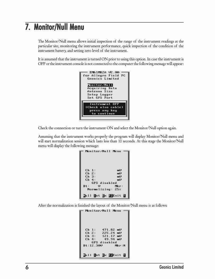
7. Monitor/Null Menu7. Monitor/Null Menu7. Monitor/Null Menu7. Monitor/Null Menu7. Monitor/Null Menu
The Monitor/Null menu allows initial inspection of the range of the instrument readings at theparticular site, monitoring the instrument performance, quick inspection of the condition of theinstrument battery, and setting zero level of the instrument.
It is assumed that the instrument is turned ON prior to using this option. In case the instrument isOFF or the instrument console is not connected to the computer the following message will appear:
Check the connection or turn the instrument ON and select the Monitor/Null option again.
Assuming that the instrument works properly the program will display Monitor/Null menu andwill start normalization session which lasts less than 10 seconds. At this stage the Monitor/Nullmenu will display the following message:
After the normalization is finished the layout of the Monitor/Null menu is as follows:

7EM61MK2 Data Logging System (DAS70/61MK2)
The EM61-MK2 readings are updated approximately 10 times per second during monitoring session.If Mode 4 was selected on the instrument panel channels 1, 2, 3, and 4 will be displayed, and whenMode D was selected (for Top and Bottom antennas) channels 1, 2, 3, and T will be given in theMonitoring menu. The level of the instrument battery is continuously updated (Bt:) in Volts. Batteryvoltage is followed by label Mkr: which indicates state of the fiducial marker. When fiducial markeris pressed then Y is displayed, otherwise label Mkr: is followed by N.
When GPS was Disabled in the Set Port for GPS menu a message GPS Disabled will be displayed.If the GPS port is Enabled and a working GPS system is connected to the field computer theMonitoring screen will display a few more parameters, as presented below.
In the above Figure one line of the display is dedicated to show the GPS status. A label DGPS(Differential Global Positioning System) indicates that GPS readings are differentially corrected inreal time, while label AGPS (Autonomous Global Positioning System) indicates lack of differentialcorrection. On the right side of DGPS or AGPS label small square is displayed. This square shouldmove down and up with the frequency of GPS update rate (usually 1 second intervals). If thesquare is not moving for long periods of time it means that the GPS system is not working or thatit is not connected to the field computer. The next label P with a value varying between 0 and 99.9represents an index called Position Dilution of Precision (PDOP). The last label S and followingnumber shows number of currently tracked satellites. Refer to section 9 (Set Port for GPS), AppendixA, and to GPS manuals for more information about GPS parameters.
A list of program functions available directly from the Monitor/Null menu is given at the botomof the screen. The screen (presented below) containing all available options is displayed after key ?or H is pressed. Available options are as follows: N - Nulling, I - Internal Q-coil calibration, E -External Q-coil calibration, M (or V) - displays field computer available memory, B - displays fieldcomputer battery level (may not work correctly for loggers other than Allegro or Pro4000), key<del> is available only in StandBy mode (see section 12), the function key F2 - exits the Monitor/Null menu.

8 Geonics Limited
7.1 Description of Monitoring/Nulling menu options7.1 Description of Monitoring/Nulling menu options7.1 Description of Monitoring/Nulling menu options7.1 Description of Monitoring/Nulling menu options7.1 Description of Monitoring/Nulling menu optionsNulling
To perform null of the instrument press the key N. At this moment the computer takes 25readings and calculates the instrument offset.
The calculated offset is applied to all the readings that follow this operation. If needed,this procedure can be repeated several times until satisfactory results are obtained. However,there is no associated “Undo” function. If original values (without calculated offsets) ofthe EM61-MK2 readings are needed, exit the EM61MK2A program and run it again. TheEM61-MK2 instrument does not have to be turned OFF. Null operation can be alsoperformed later during data collection.
Internal QC Coil Calibration
The Internal QC coil calibration is described in detail in the EM61-MK2 OperatingInstructions.
To start the calibration using Internal QC coil press key I. This action begins by performingthe automatic nulling which in this case is only in effect for the duration of the calibrationprocess. It will not affect EM61-MK2 readings. After the nulling is completed (less than 5seconds) the Internal QC coil Calibration screen is displayed.
This screen displays timer with elapsed seconds and EM61-MK2 readings. This displaylasts for 60 seconds. During this time please follow the instructions provided on the Allegroscreen.

9EM61MK2 Data Logging System (DAS70/61MK2)
Calibration can end in the following four ways:
The process can be stopped by an operator at any time by pressing key <Esc>.
The calibration may end by time out (60 seconds) if QC coil button was notpressed or this action did not activate QC coil. The following screen will then bedisplayed:
After pressing any key the program returns to Monitoring/Nulling manu. To repeatInternal QC coil calibration please press key I again.
The logger will determine if the instrument has passed test. If after activating theQC coil, the program determines that the reading is inside the standard valueswithin +/- 10% tolerances then a message “CALIBRATION OK” will be displayed(see below).
Otherwise, if the program determines that the reading is outside of the test valuesrange the corresponding message “CALIBRATION FAILED” is displayed.

10 Geonics Limited
Regardless of the test result (OK or FAILED) the readings will be saved on screen. Theprogram returns to Monitoring/Nulling menu after any key is pressed. Then the calibrationprocess can be repeated.
External QC Coil Calibration
The External QC coil calibration is described in detail in the EM61-MK2 OperatingInstructions.
The procedure for the instrument check using External QC coil calibration is very similarto the one described above for Internal QC coil calibration. To start the calibration processusing External QC coil press key E . This action begins by performing the automatic nullingwhich in this case is only in effect for the duration of the calibration process. It will notaffect EM61-MK2 readings. After the nulling is completed (less than 5 seconds) the ExternalQC coil Calibration screen is displayed.
This screen displays timer with elapsed seconds and EM61-MK2 readings. This displaylasts for 60 seconds. During this time please follow the instructions provided on the Allegroscreen.
Calibration can end in the following four ways:
The process can be stopped by ann operator at any time by pressing key <Esc>.
The calibration may end by time out (60 seconds) if QC coil button was notpressed or this action did not activate QC coil. After pressing any key the programreturns to Monitoring/Nulling manu. To repeat External QC coil calibration pleasepress key E again.
The logger will determine if the instrument has passed test. If after activating theQC coil, the program determines that the reading is inside the standard valueswithin +/- 10% tolerances then a message “CALIBRATION OK” will bedisplayed.
Otherwise, if the program determines that the reading is outside of the test valuesrange the corresponding message “CALIBRATION FAILED” is displayed.
Regardless of the test result (OK or FAILED) the readings will be saved on screen. Theprogram returns to Monitoring/Nulling menu after any key is pressed. Then the calibrationprocess can be repeated by pressing key E .

11EM61MK2 Data Logging System (DAS70/61MK2)
Memory Check
After key M (or V) is pressed a small window that shows the amount of available memoryfor data is displayed. The amount of available memory is given in Kbytes and in numberof EM61-MK2 readings (one EM61-MK2 record is 22 bytes long). If GPS data is takenconcurrently, one GPS record is equal to 5 or 6 EM61-MK2 readings (110 or 132 bytes).
Available memory is also checked automatically during data collection. In cases where theamount of available memory in the logger is less than 10 Kbytes, the program will stop,data file will close, and a proper message will be displayed.
Battery Check
After key B is pressed a small window that shows the voltage of Allegro or Pro4000battery (in Volts) is displayed. If other than Allegro or Pro4000 field computer is used thedisplayed value may not be accurate (as shown in Figure below).
In addition Allegro and Pro4000 systems will also warn the user when battery voltage istoo low.
Help Screen
When key ? or H is pressed a help screen that list all available options is displayed.
Option “<Del> Delete Reading” is available only during data collection.

12 Geonics Limited
Exit Monitor/Nulling menu
To exit the Monitor/Null option press the function key F2.
8. Logger Setup Menu8. Logger Setup Menu8. Logger Setup Menu8. Logger Setup Menu8. Logger Setup Menu
This option allows you to set several parameters in the logger. The Logger Set Up menu is presentedbelow.
Description of Parameters:
DateThis option allows you to change the date in the field computer clock. When the option ishighlighted pressing the ENTER, or Left or Right arrow keys, enables editor that allowsthe operator to change day, month and year.The new date is accepted (and set in the computer) after the function key F1 is pressed.Use Down or Up arrow key to exit the editor and cancel any changes.

13EM61MK2 Data Logging System (DAS70/61MK2)
TimeThis option allows you to change time of the day in the field computer clock. When thisoption is highlighted pressing the ENTER, or Left or Right arrow keys, enables editorthat allows the operator to change hour, minute, and second.
The modified time is accepted (and set in the computer clock) after the function key F1 ispressed.Use Down or Up arrow key to exit the editor and cancel any changes.
UnitsTwo selections are available: Meters or Feet.
COM PortThe number of serial port that is assigned to the EM61-MK2. Available selections: COM1and COM 2. The program default is COM1. Communication parameters for the selectedserial port are set by the program, since the EM61-MK2 operates Baud Rate (9600), Parity(N), Data Bits (8), and Bit Stop (1).This port must be different than the port specified in the Set Port for GPS menu (seenext), otherwise a message will be displayed and ports will have to be reassigned.
AudioTwo selections are available: Yes or No. The audible click will be generated at each readingwhen this option is enabled.

14 Geonics Limited
Pause keyThree selections are available: Any key, Alt+F1, and Ctrl+F5. This feature is used topause data recording during logging session. Default setting Any key can be changed toone of the two key combinations for field conditions where a logger key can be accidentallypushed causing unwanted stop of data logging.
DisplayThis parameter specifies the display type during data collection. Two types of the displaycan be selected: Text mode or Graphic mode.In the text mode data for four channels is displayed in digital form. This mode isrecommended for the instrument AUTO mode when the highest possible frequency ofdata collection is used. The same applies to Wheel mode since the data triggering can beaccelerated at any given moment (while passing a curb, downhill, etc.).The graphic mode allows to display profiles for any selected channels in real time as well assimultaneous display of readings in digital form for all four channels. When the DisplayGraphic is selected, five additional parameters are activated (see menu below).
Parameters Ch 1, Ch 2 , Ch 3, and Ch 4 (applies to Ch T as well ) allow you to enable (Yes)or disable (No) display of each channel separately, while the option Amp. (AmplitudeScale) can be selected as Compressed scale or Linear scale. The compressed amplitudeallows you to display the high dynamic range of the EM61-MK2 data in a legible way andis recommended.Regardless of which channels are chosen, data for all four channels will be displayed indigital form below profile display.
Please note, that readings in digital form are always given in mV (linear scale) regardlessof the amplitude scale (compressed or linear) selection. Further, graphic display in thecompressed scale does not affect readings saved in the data file. Data are always written tofile in original form.
After all the parameters in the Logger Setup menu are updated press the function key F1 to acceptthe displayed settings. The program will return to the Main menu.
To return to the original settings (state before this option was selected) press the function key F2.All parameters will be reset to the initial settings and the program will return to the Main menu.

15EM61MK2 Data Logging System (DAS70/61MK2)
9. Set P9. Set P9. Set P9. Set P9. Set Port for GPS Menuort for GPS Menuort for GPS Menuort for GPS Menuort for GPS Menu
After the Set Port for GPS option is selected in the Main Menu the Set Port for GPS menu appearson the screen. This menu allows you to enable and disable the GPS input, specify serialcommunication parameters matching GPS receiver settings, and to monitor the GPS output interminal mode (key F3). The menu is presented below.
GPS InputThis option allows you to Enable/Disable a serial port for GPS input. When Disabled ischosen logging and monitoring screens will display message “GPS disabled” in place ofGPS parameters.The GPS Input can be Enabled even if there is no GPS system connected to the Allegro.In such case data file will contain proper sequence of EM61-MK2 readings without anyGPS input.
COM PortThe number of serial port that is assigned to the GPS input. Available selections: COM1and COM 2. The program default is COM2. Communication parameters for the selectedserial port can be determined in options described below.This port must be different than the port specified in the Logger Set Up menu (for EM61-MK2), otherwise a message will be displayed and ports will have to be reassigned.
Baud RateSpecify Baud Rate for the output port, the selected value should much the Baud Rate ofthe GPS system, default is 9600.
ParitySelect Parity for the output port, the entered parameter should much the Parity set in theGPS serial port settings, default is N.
Data BitsSpecify Data Bits for the output port, the entered value should much settings in the GPSsystem, default is 8.
Stop BitsSpecify Stop Bits for the output port, the entered value should much settings in the GPSsystem, default is 1.

16 Geonics Limited
After all the parameters in the Logger Setup menu are updated press the function key F1 to acceptthe displayed settings. The program will return to the Main menu.
To return to the original settings (state before this option was selected) press the function key F2.All parameters will be reset to the initial settings and the program will return to the Main menu.
To activate terminal mode which allows you to monitor GPS receiver output press the function keyF3. The monitoring mode will work regardless of the GPS Input being Enabled or Disabled. Thisoption is described in the following section.
9.1 Monitoring GPS R9.1 Monitoring GPS R9.1 Monitoring GPS R9.1 Monitoring GPS R9.1 Monitoring GPS Receiver Outputeceiver Outputeceiver Outputeceiver Outputeceiver OutputAfter the function key F3 is pressed in Set Port for GPS menu the program will display the screenin terminal mode. In this mode the screen is divided into three parts. The top portion of thescreen, labeled Receive GPS Data, displays the GPS receiver output. The middle portion labeledNMEA Command is used to enter NMEA commands to be sent to the GPS receiver, and at thebottom, the screen menu with available options is displayed. This screen is shown below.
As soon as the EM61MK2A screen is in terminal mode and the GPS is streaming data, the first 20characters of each message will appear in the top portion of the display. The display is updatedwith the frequency the GPS receiver outputs data. This allows you to recognize the GPS updaterate and type of messages being sent by the connected GPS. In cases where the GPS data is notreceived by the logger a message NO DATA and current time will appear in the top window of thedisplay, as shown below.
The message NO DATA is normally updated with a rate of 6 seconds. This may indicate thefollowing: serial port number not correctly specified in Set Port for GPS menu, GPS receiver not

17EM61MK2 Data Logging System (DAS70/61MK2)
sending any data, and not working or not connected GPS receiver. If the message is updated moreoften than 6 seconds (i.e. every 1 or 2 seconds) or the display doeas not show legible characters, itis possible that the GPS is working correctly and is connected to the proper serial port, howevercommunication parameters are not specified correctly. In most cases the Baud Rate or Parity mustbe adjusted.
The NO DATA message may also appear if the GPS data are received correctly, but the GPSreceiver was set to send data with a time interval longer than 6 seconds. In this case the NO DATAmessage will be displayed in between GPS messages. This indicates that the GPS is working correctly,however the operator should consider adjustment of the GPS receiver output update rate. Mosthigh resolution geophysical surveys require positioning update of 1 or 2 seconds, and a 5 secondsinterval can be used only when the survey is carried out at an even pace and along relatively straightsurvey lines.
The monitoring display can be stopped any time by pressing the function key F1 (labeled Stop). Atthat time scrolling of the GPS output will be stopped, and the function key F1 will be labeled Go.The next pressing of this key will activate receiving and display of GPS data.
The function key F2 allows you to send a NMEA command to the GPS receiver. It is preferable ifthe GPS receiver parameters are set using the GPS manufacturer software or controller (GPSlogger or panel keys). However, when the operator is familiar with NMEA protocol andstructure of commands for a given GPS system, this function can be very convenient anduseful when the update rate and enabling or disabling messages in the data stream is required.
After the function key F2 is pressed the portion of the screen labeled NMEA Command is activatedand the beginning of the standard NMEA command, $PASHS, is displayed. After the entireNMEA command is typed in, press the key <ENTER> to send the command to the GPS receiver.Pressing the <Esc> key will cancel the command and deactivate the NMEA Command window.An example of a command that will remove the NMEA message SAT is given in the below figure(it is assumed that the GPS receiver output serial port is A).
After this command is reived by the GPS receiver, the confirmation message will be send by thereceiver ($PASHR, ACK*3D) and data stream will not contain the message SAT ($PASHR, SAT,.....in the above figure).
Please note, that not every GPS system accepts and uses the same standard set of NMEA commandsand messages. In addition, some GPS systems do not accept commands sent by the serial port atall. The configuration of these type of receivers can be updated only by the controlling device(usually GPS logger, controllel, or the receiver panel keys).

18 Geonics Limited
10. Set Output P10. Set Output P10. Set Output P10. Set Output P10. Set Output Portortortortort
This option can be used to enable simultaneous output of collected data through selected serialport. Data can be sent to other logging devices, including remote computers connected by wirelessmodem or digital radio.
After the Set Output Port option is selected in the Main Menu the Set Output Port menu appearson the screen. This menu allows you to enable and disable the serial port output, specify format ofthe output, and to select serial communication parameters matching an external device settings.The menu is presented below.
OutputThis option allows you to Enable/Disable a serial port output.If the Output function is not used please select Disabled, otherwise the program performsthis task unnecessarily.
FormatThis option allows you to specify format of the output string: Raw Data or Converted.The Raw Dara format indicates that the string will be sent in binary format (22 bytes longrecords) and the format is exactly the same as the raw data file format (R61) described inAppendix A. Data file collected in the external device may be converted to ASCII formatusing the option Convert in the data processing program DAT61MK2.If Converted is selected then the string sent by the output serial port will contain converteddata in mV and GPS NMEA message will be sent as it is received from the employed GPSreceiver. The example of output data format is shown in Appendix B.The Raw Data format is preferable since it is more than three times smaller.
COM PortThe number of serial port that is assigned to the serial output. Available selections: COM1,COM2, COM3, and COM 4. The program default is COM3. Communication parametersfor the selected serial port can be determined in options described below.This port must be different than the port specified in the Logger Set Up menu (for EM61-MK2 and GPS), otherwise a message will be displayed and ports will have to be reassigned.

19EM61MK2 Data Logging System (DAS70/61MK2)
Baud RateSpecify Baud Rate for the output port, the entered value should much the Baud Rate ofthe GPS system, default is 9600.
ParitySelect Parity for the output port, the entered parameter should much the Parity set in theGPS serial port settings, default is N.
Data BitsSpecify Data Bits for the output port, the entered value should much settings in the GPSsystem, default is 8.
Stop BitsSpecify Stop Bits for the output port, the entered value should much settings in the GPSsystem, default is 1.
11. Advanced COM Setup11. Advanced COM Setup11. Advanced COM Setup11. Advanced COM Setup11. Advanced COM Setup
The Advanced COM Setup menu, presented below, allows for specifying parameters of each selectedserial port.
To select any option use the Down and Up keys. To start the editing of any setting press Left orRight key. Parameter Irq (from 1 to 15) can be simply toggled by Left or Right keys, while Addressmust be typed in for each serial port.
The Allegro (or Pro4000) two serial ports have parameters:
COM1 - base I/O address 3F8, IRQ 4COM2 - base I/O address 2F8, IRQ 3
These are standard settings in MS DOS operating system. Names for additional serial ports (COM3 and COM4) have only identification meaning in DOS environment, and they are fully describedby I/O address and interrupt level.

20 Geonics Limited
Please note, that in this menu, when i.e. port name COM4 is given the address 3F8 and IRQ 4,physically it will refer to Allegro COM1 port connector. At the same time the serial port nameCOM1 can be given different address and IRQ level.
The base I/O address of the extension card is given in hexadecimal notation and resides on aneven 32-byte (20H) boundary. This address is assigned usually to the first serial port of the card.The following ports require 8 bytes of I/O space for each port.
Settings shown in the menu describe COM1 as a standard Allegro (or Pro4000) serial port COM1,and two ports COM3 and COM4 (associated with extension card) are set based on the assigned I/O Base Address 380H and IRQ 5 for the serial extension card. This base address is usually displayedduring rebooting Allegro and Pro4000 (see Appendix D).
Please note that any names from COM1 to COM12 can be specified in proper menus, as long ascorrect parameters (address and IRQ level) will be assigned to these names in Advanced COMSetup menu.
Please refer to Appendix D (PCMCIA Card Installation) of this manual or to serial extension cardmanufacturer documentation for more information regarding serial port settings.
After all the parameters in the Advanced COM Setup menu are updated press the function key F1to accept the displayed settings. The program will return to the Main menu. Updated settings willbe written to the initial file and they will be given as default parameters in the subsequent SystemSetup menu display.
To return to original settings (state before this option was selected) press the function key F2. Allparameters will be reset to initial settings and the program will return to the Main menu.

21EM61MK2 Data Logging System (DAS70/61MK2)
12. Acquiring Data Menu and Logging12. Acquiring Data Menu and Logging12. Acquiring Data Menu and Logging12. Acquiring Data Menu and Logging12. Acquiring Data Menu and Logging
After the Acquiring Data option is selected in the Main Menu the Acquiring Data menu appears onthe screen. This menu is presented below.
At the top of the screen the current name of the data file is displayed. If data file is not created itsname is displayed as NONE. The menu contains several options listed below.
Create FileThis option creates data file.
Survey SetupThe Survey Setup menu will be displayed. Instrument mode and survey settings can bespecified in this menu.
Preset SetupsList of 10 predesigned survey setups will be displayed. Each survey setup can be editedand saved by the user for later use.
LOG DATAThis option is used for actual monitoring and logging EM61-MK2 data.
Main MenuThe program returns to the EM61MK2A Main Menu.
End ProgramExecuting this option will end the program.
12.1 Create File Menu12.1 Create File Menu12.1 Create File Menu12.1 Create File Menu12.1 Create File MenuThe Create File option can be executed before or after the Survey Setup parameters are specified.
The log file is created in the current directory (containing the EM61MK2A program). The name ofthe file is given by the field computer clock and it consists of month (2 digits), day (2 digits), hour(2 digits), and one alphabetic character A, B, C, etc. (If all letters during one hour are used use theOverwrite option). The Create File menu is presented below.
The file can be created by pressing the function key F1, this option can be skipped by pressing the

22 Geonics Limited
function key F2., or by pressing key F3 the file name can be overwritten. After key F3 is pressed theCreate File menu will be displayed as follows.
Each data file in the field computer (raw data file) has an extension name R61 and it is created in theprogram current directory. The R61 files are created in the instrument binary format. They can beviewed using the Main menu option “View Files”. These files can be also converted to ASCIIformat and processed in the Geonics program DAT61MK2.
12.2 Survey Setup Menu12.2 Survey Setup Menu12.2 Survey Setup Menu12.2 Survey Setup Menu12.2 Survey Setup MenuThe Survey Setup menu, presented below, contains several parameters which affect two importantprocedures: instrument settings (instrument mode, frequency of data collection, etc.) and surveygeometry layout (survey line names, line spacing, start station, station increment, etc.).

23EM61MK2 Data Logging System (DAS70/61MK2)
To select any option use the Down and Up keys. To start the editing of any setting press Left orRight key. Some parameters that have only a few possible options (e.g. EM61 Mode) can be simplytoggled by Left or Right keys.
Description of the Survey Setup menu options and parameters.
EM61-MK2 ModeSet the EM61MK2 mode of operation by pressing Left or Right arrow keys. Availablemodes are: Auto, Wheel, and Manual. These modes of operation are described below.
Auto ModeReadings will be triggered automatically at a specified frequency (see optionReadings/s).Please note that when Auto mode is selected parameter Wheel Inc. is not available,see figure above. At the same time the Stn Incr (station increment) has only twooptions: Positive or Negative.
Wheel ModeReadings will be triggered automatically by a counter attached to the wheel. Wheelincrement is approximately 20 cm (or 0.64 foot) for the EM61-MK2 equippedwith 1 x 0.5 m or 1 x 1 m antennas. The Hand Held EM61HH-MK2 has twowheel increments 0.1 and 0.2 m. Check the wheel increment setting on the antennaassembly.Please note that when Wheel mode is selected option Reading/s is not available,see figure below. At the same time the station increment (Stn Incr) has only twooptions: Positive or Negative.
Manual ModeReadings will be taken only while the manual trigger (switch on the logger cable)is pressed. This mode may be used only in very specific applications since thehighly dynamic EM61-MK2 response requires finely spaced data points.Please note that when Manual mode is selected options Wheel Inc. and Reading/s are not available. In this mode any value can be entered for the station increment(Stn Incr) parameter.

24 Geonics Limited
Wheel Inc.When this option is highlighted press Left or Right arrow key to activate editor and thenenter desired value.Wheel increment is approximately 20 cm (or 0.64 feet) for the EM61-MK2 equipped with1 x 0.5 m, 1 x 1 m, and 0.5 x 0.5 m antennas. The Hand Held EM61-MK2 has two wheelincrements 0.1 and 0.2 m. Check the wheel increment setting on the antenna assembly.This option is available only when the Wheel mode was selected.Use Down or Up arrow key to leave editor.
Readings/sWhen this option is highlighted press Left or Right arrow key to activate editor and thenenter desired value.This parameter describes number of readings per second that will be taken. Any numberlarger than zero can be entered, however the EM61-MK2 maximum frequency of dataoutput is 16 readings per second.At high frequencies (above 10 readings per second) obtained frequency may differ fromthe specified rate, however speed of data collection will be consistent for a given fieldcomputer. The real speed of data collection (in Auto mode) depends on the field computerused and display type. In general, displaying data in the text mode allows for faster datacollection and while using fast computers the difference between specified and obtainedfrequency is very small.This parameter is available only when the Auto Mode was selected.Use Down or Up arrow key to leave editor.
Surv Line (survey line name)When this option is highlighted press Left or Right arrow key to activate editor and thenenter desired value. Use Down or Up arrow key to leave editor.This is a user’s tag number/name for the profile line. The length of the name can notexceed 8 characters. The line name is usually used as a coordinate perpendicular to thesurvey lines direction. For example, when survey lines are laid out along W-E directionstations describe W-E coordinate, while Line names may describe S-N (vertical on a map)coordinate.
Line Incr. (survey line name)When this option is highlighted press Left or Right arrow key to activate editor and thenenter desired value.This parameter specifies the distance by which survey lines will be separated. This setting

25EM61MK2 Data Logging System (DAS70/61MK2)
will be used to determine number (name) of the next survey line.Use Down or Up arrow key to leave editor.
SequenceWhen this option is highlighted press Left or Right to toggle between two available settings:Alternate and One Way.Alternate is used when neighboring lines are surveyed in the opposite direction, which isthe most common procedure during field surveys.One Way is used when each survey line is traversed in the same direction.The choice of this parameter will affect the default start station, a signature of the stationincrement, and line direction when parameters for the next survey lines is determined.
DirectionWhen this option is highlighted press Left or Right to toggle between four availablesettings: East, West, South, and North.This parameter indicates the heading of the survey line.Use Down or Up arrow key to leave editor.
Start Stn (start station of a survey line)When this option is highlighted press Left or Right arrow key to activate editor and thenenter desired value.This parameter specifies the starting station number for the selected survey line. Thisvalue is used in conjunction with Station Increment to calculate the current station numberfor display purposes.Use Down or Up arrow key to leave editor.
Stn Incr (station increment)When this option is highlighted press Left or Right arrow key to activate editor.In case the EM61-MK2 Manual mode was selected enter desired value for the stationincrement. If Auto or Wheel modes were selected then, the Left and Right arrow keyswill toggle between two available options: Positive and Negative.This parameter specifies the station increment for the selected survey line. This value isused in conjunction with Start Station to calculate the current station number for displaypurposes.In Auto mode the increment is assumed +1 (Positive) or -1 (Negative), while in Wheelmode it will be Positive or Negative value of the specified Wheel Increment.Use Down or Up arrow key to leave editor.
After all the parameters in the Survey Setup menu are updated press the function key F1 to acceptthe displayed settings. The program will return to the Acquiring Data menu. Updated settings willbe written to the initial file and they will be given as default parameters in the subsequent SurveySetup menu display.
To return to original settings (state before this option was selected) press the function key F2. Allparameters will be reset to initial settings and the program will return to the Acquiring Data menu.

26 Geonics Limited
12.3 Survey Setups12.3 Survey Setups12.3 Survey Setups12.3 Survey Setups12.3 Survey SetupsThe Preset Survey Setups menu, presented below, contains list of ten predesigned Survey Setup.Each Survey Setup can be configured and saved by the user for subsequent use. As a defaultsurveys 1 to 4 are assigned for various settings of survey conducted in EM61-MK2 Wheel mode,surveys 5 to 8 contain settings for EM61-MK2 Auto mode, and surveys 9 and 10 are set for theEM61-MK2 Manual mode.
To select any survey set up number use Down and Up keys, and to start editing particular SurveySetup menu press <ENTER>. Press <Esc> key. to return to the Acquiring Data menu.
After a Survey Setup number (e.g. Survey Set Up #2) is selected the following screen will appear:
The survey parameters are updated in the exactly same way as in the Survey Setup menu (seesection 12.2).
After all parameters are specified three options represented by function keys F1, F2, and F3 areavailable :
F1 (OK)The display returns to Acquiring Data menu. The selection will become the current SurveySetup parameters, however settings will not be saved as a Survey Setup # for subsequentuse.
27EM61MK2 Data Logging System (DAS70/61MK2)
F2 (Cancel)The display returns to Acquiring Data menu. The selection is cancelled and it will not besaved.
F3 (Save)The selection is saved as a particular Survey Setup number. The display does not return toAcquiring Data menu, nor it becomes the current Survey Setup. In order to use the editedparameters as a current Survey Setup use function key F1.
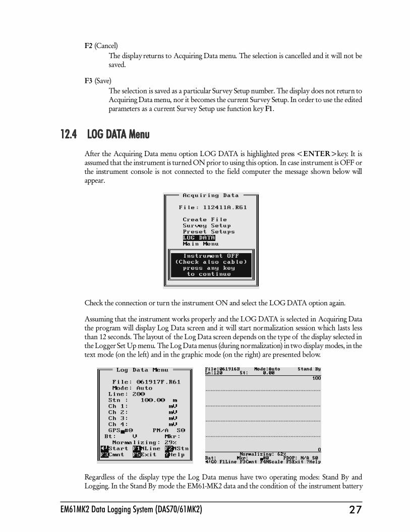
12.4 L12.4 L12.4 L12.4 L12.4 LOG DOG DOG DOG DOG DAAAAATTTTTA MenuA MenuA MenuA MenuA MenuAfter the Acquiring Data menu option LOG DATA is highlighted press <ENTER> key. It isassumed that the instrument is turned ON prior to using this option. In case instrument is OFF orthe instrument console is not connected to the field computer the message shown below willappear.
Check the connection or turn the instrument ON and select the LOG DATA option again.
Assuming that the instrument works properly and the LOG DATA is selected in Acquiring Datathe program will display Log Data screen and it will start normalization session which lasts lessthan 12 seconds. The layout of the Log Data screen depends on the type of the display selected inthe Logger Set Up menu. The Log Data menus (during normalization) in two display modes, in thetext mode (on the left) and in the graphic mode (on the right) are presented below.
Regardless of the display type the Log Data menus have two operating modes: Stand By andLogging. In the Stand By mode the EM61-MK2 data and the condition of the instrument battery

28 Geonics Limited
are monitored with the update rate of approximately 10 times per second. In this mode the operatorcan monitor the instrument output (without recording the data), GPS parameters (if Enabled), aswell as change the operation to the Logging mode, and access several field options. In the Loggingmode when the EM61-MK2 data is recorded in the data file, field options can not be accessed.
When the Log Data menu is displayed for the first time it appears always in the Stand By mode.
Stand By mode
The Log Data menus in two display modes, in the text mode (on the left) and in the graphic mode(on the right) are presented below.
The main portion of the screen in the graphic mode is occupied by the plot area. Readings in theplot area can be displayed in compressed amplitude scale (recommended and shown in this manualfigures), which corresponds to Square Root of the amplitude. In compressed amplitude scale 0 to100 corresponds to 0 to 10,000 mV, and compressed range 0 to 200 corresponds to 0 to 40,000 mV.Plotting data in compressed amplitude allows to show details in the low range of amplitude, as wellas relatively good resolution in the high range of data on the small screen. Please note, that datadisplayed in the digital form are always given in the standard, linear scale. The amplitudescale is divided by four or five dotted grid lines. In the case where the amplitude scale starts with anegative value, then the grid line corresponding to zero is always plotted as a solid line.
Readings for channels 1, 2, 3, and 4 (or T) are shown in digital form in the central portion of thescreen in the text mode, and below plot area in the graphic mode. The EM61MK2A programprepared for the Allegro field computer, displays labeled channels in graphic mode. Units (mV) arenot displayed in the graphic mode. If program EM61MK2P is used in graphic mode labels are notdisplayed due to smaller screen in Pro4000. Values of readings are displayed in the following order(from the left): Channel 1, 2, 3, and 4 (or T).
Both modes show the log file name and optional GPS parameters. Name of the Log Data menumode is displayed in the text mode, and it is shown as an abbreviation in the top right corner of thescreen in graphic mode, STB for Stand By mode, and LOG for logging mode. The instrumentbattery level (Bt) is updated continuously (in Volts) in both modes.
Current survey line name and station number is displayed at the top of the screen. In the Stand Bymode the station number will not change. Stations in the EM61MK2A program are incrementedby 1 or station increment value after each reading is written to the data file.
Similarly, the stations with the GPS readings (assuming that the GPS is connected to the logger)remain the same in the Stand By mode. Number of GPS positions is incremented by 1 after each

29EM61MK2 Data Logging System (DAS70/61MK2)
GPS reading is written to the data file. In the text mode number of GPS positions follows labelDGPS (or AGPS positions are not differentially corrected), the corresponding label in graphicmode is D (or A). Small square moving up and down in Stand By mode indicates that the GPSsystem is monitored and it is working. Two other GPS parameters: PDOP (represented by label P)and Number of Tracked Satellites (label S) are updated continuously in Stand By mode.
Several available field options are listed at the bottom of the Stand By mode screen. They will bedescribed in the following section 12.5.
Logging Mode
The Logging mode is enabled by pressing the <ENTER> key, which corresponds to label Start inthe Text Display, and GO in the Graphic display mode. After this key is pressed the bottom portionof the screen will change and data will be logged in the mode corresponding to the selected EM61-MK2 mode in the Survey Setup menu. Log Data screens in logging mode in the text (on the left)and graphic (on the right) display modes are presented below.
After the screen changes to Logging mode current station (Stn in Text and St in Graphic displaymode) is updated according to the station interval. Similarly, if GPS Input was enabled, totalnumber of GPS positions in the data file is incremented every time (usually once a second) GPSposition is written to the file. If the Graphic display mode is enabled profiles (or profile) curves areupdated after each reading is written to the data file. The audible click sounds at each reading ifSound option was enabled in the Setup Logger menu.
There is only one option available in the Logging mode - pause logging. After a Pause key (any key,Alt+F1, or Ctrl+F5) selected in Logger Setup menu is pressed the recording is stopped and theLog Data menu returns to the Stand By mode. The EM61-MK2 data will be displayed with theupdate rate approximately 10 readings per second, however data will not be saved in the log file,audible click will stop if Sound option was enabled, and if graphic mode is used, profile curves willbe not updated.
Exit from the logging session and access to field options are available only from the Log Datamenu in the Stand By mode.

30 Geonics Limited
12.5 Field Options12.5 Field Options12.5 Field Options12.5 Field Options12.5 Field OptionsSeveral field options are available while the Log Data screen is in the Stand By mode. These optionsare listed at the bottom of the screen.
<ENTER>This option is labeled Start in the Text display mode, and GO in the Graphic displaymode. The Log Data screen changes from Stand By to Logging.
? or H (Help)This option displays a window that lists additional, less frequently used options which arenot visible on the main screen, however they are available while the program is running.These are: Nulling, Internal QC Coil Calibration, External QC Coil Calibration, MemoryCheck, Battery Level (for logger), Delete Reading, and New Station.
F1 (New Line)This option is labeled NLine in the Text display mode, and L in the Graphic displaymode. The New Line menu is displayed, which is the same for Text and Graphic displaymodes.Selecting this option allows the operator to enter a new survey line number (name) andassociated information (Direction, Start Station, and Station Increment). The new linenumber and associated parameters will be prompted by the program based on parametersspecified in the Survey Setup menu.
At the top of the screen the last survey line name and the last station are displayed. Defaultname for the new line is given based on the Line Increment parameter. The default Start

31EM61MK2 Data Logging System (DAS70/61MK2)
Station, direction of the Station Increment, and Direction are determined based on Sequenceselection. All these parameters can be overwritten by the user as described in the SurveySetup menu description (section 10.2).After selection is updated, it can be accepted by pressing the function key F1. The displayreturns to the Log Data screen with new settings for the new survey line.Pressing key F2 or <Esc> will disregard any New Line menu changes and the programwill return to the Log Data screen and measurements can be continued.
F2 (New Station)This option is labeled NStn in the Text display mode, and S in the Graphic display mode.The New Station menus in two display modes, in the text mode (on the left) and in thegraphic mode (on the right) are given below.
Selecting this option allows the operator to enter a new station number. In the Text modeStart Station and Current Stations are displayed at the top of the screen. In the Graphicmode only the Current Station is displayed. The New Station can be entered in the similarway as editing parameters in Survey Setup menu, and in the provided message box in theGraphic display mode.After the New Station is entered, it can be accepted by pressing the function key F1. Thedisplay return to the Log Data screen with new station..Pressing key F2 or <Esc> will disregard new entry and the program will return to the LogData screen and measurements can be continued.
F3 (Comment)This option is labeled Cmnt in the Text display mode, and C in the Graphic display mode.Menus containing Enter Comment box in the text mode (on the left) and in the graphicmode (on the right) are given below.

32 Geonics Limited
Selecting this option allows the operator to enter a comment at any point of the survey. Amaximum of 11 characters can be entered as a comment. Text of the comment is saved inthe file with a corresponding time stamp.The user must exit the comment mode by pressing <ENTER> key.
F4 (New Scale) only graphic displayThis option is available only in the Graphic display mode and it is labeled N. The Log Datascreen with the entry box for New Scale parameters is given below.
Selecting this option allows the operator to enter new scale parameters for the amplitudedisplay. After minimum and maximum values are specified, the function key F1 (OK) willaccept new values and the display will be redrawn (see below). When the key F2 (Cancel) ispressed the new entry is cancelled.
<Del>(delete reading)This option is labeled Rdg in both display modes. The Delete Reading box that appearson the screen, in the text mode (on the left) and in the graphic mode (on the right) isshown below.

33EM61MK2 Data Logging System (DAS70/61MK2)
This function allows operator to delete previously recorded reading(s). The reading (station)to be deleted is displayed on the screen. The data will only be deleted when the key D ispressed. The program will then display the next previous station, and allow it to be deletedin a similar fashion. If there is no further data available, the program will provide relatedinformation.To exit delete reading mode press key E .
N (Nulling)
To perform null of the instrument press the key N. During data collection a confirmationmessage will be displayed (there is no such message if Nulling is performed in Monitoring/Nulling menu).
After above message is confirmed the program collects 25 readings and calculates theinstrument offset.
The calculated offset is applied to all the readings that follow this operation. If needed,this procedure can be repeated several times until satisfactory results are obtained. However,there is no associated “Undo” function. If original values (without calculated offsets) ofthe EM61-MK2 readings are needed, exit the EM61MK2A program and run it again. TheEM61-MK2 instrument does not have to be turned OFF.
I (Internal QC Coil Calibration)
The Internal QC coil calibration is described in detail in the EM61-MK2 OperatingInstructions.To start the calibration using Internal QC coil press key I. This action begins by performingthe automatic nulling which in this case is only in effect for the duration of the calibrationprocess. It will not affect EM61-MK2 readings. After the nulling is completed (less than 5seconds) the Internal QC coil Calibration screen is displayed.

34 Geonics Limited
This screen displays timer with elapsed seconds and EM61-MK2 readings. This displaylasts for 60 seconds. During this time please follow the instructions provided on the Allegroscreen.
Calibration can end in the following four ways:The process can be stopped by an operator at any time by pressing key <Esc>.The calibration may end by time out (60 seconds) if QC coil button was notpressed or this action did not activate QC coil (see following Figures). After pressingany key the program returns to Monitoring/Nulling manu. To repeat Internal QCcoil calibration please press key I again.
The logger will determine if the instrument has passed test. If after activating theQC coil, the program determines that the reading is inside the standard valueswithin +/-10% tolerances then a message “CALIBRATION OK” will be displayed:
Otherwise, if the program determines that the reading is outside of the test valuesrange the corresponding message “CALIBRATION FAILED” is displayed.

35EM61MK2 Data Logging System (DAS70/61MK2)
Regardless of the test result (OK or FAILED) the readings will be saved on screen. Theprogram returns to Monitoring/Nulling menu after any key is pressed. Then the calibrationprocess can be repeated.
E (External QC Coil Calibration)
The External QC coil calibration is described in detail in the EM61-MK2 OperatingInstructions.The procedure for the instrument check using External QC coil calibration is very similarto the one described above for Internal QC coil calibration. To start the calibration processusing External QC coil press key E . This action begins by performing the automatic nullingwhich in this case is only in effect for the duration of the calibration process. It will notaffect EM61-MK2 readings. After the nulling is completed (less than 5 seconds) the ExternalQC coil Calibration screen is displayed.
This screen displays timer with elapsed seconds and EM61-MK2 readings. This displaylasts for 60 seconds. During this time please follow the instructions provided on the screen.
Calibration can end in the following four ways:The process can be stopped by ann operator at any time by pressing key <Esc>.The calibration may end by time out (60 seconds) if QC coil button was notpressed or this action did not activate QC coil. After pressing any key the programreturns to Monitoring/Nulling manu. To repeat External QC coil calibration pleasepress key E again.The logger will determine if the instrument has passed test. If after activating theQC coil, the program determines that the reading is inside the standard valueswithin +/-10% tolerances then a message “CALIBRATION OK” will be displayed.Otherwise, if the program determines that the reading is outside of the test valuesrange the corresponding message “CALIBRATION FAILED” is displayed.

36 Geonics Limited
Regardless of the test result (OK or FAILED) the readings will be saved on screen. Theprogram returns to Monitoring/Nulling menu after any key is pressed. Then the calibrationprocess can be repeated by pressing key E .
M or V (memory check, no prompt on the screen)This option is not shown on the screen. After key M or V is pressed a small window thatshows the amount of available memory for data is displayed. The amount of availablememory is given in Kbytes and in number of EM61-MK2 readings (one EM61-MK2record is 22 bytes long). If GPS data is taken concurrently, one GPS record is equal to 5 or6 EM61-MK2 readings (110 or 132 bytes).
Available memory is also checked automatically during data collection. In cases where theamount of available memory in the logger is less than 10 Kbytes, the program will stop,data file will close, and a proper message will be displayed.
B (Battery Check)
After key B is pressed a small window that shows the voltage of Allegro or Pro4000battery (in Volts) is displayed. If other than Allegro or Pro4000 field computer is used thedisplayed value may not be accurate. In addition Allegro and Pro4000 systems will alsowarn the user when battery voltage is too low.
F5 (exit LOG DATA mode)This option is labeled Exit in the text display mode, and X in the graphic display mode.After key F5 is pressed a confirmation prompt Exit Logging Y(es)/N(o) will appear:
When the key Y is pressed the data file is closed and the program returns to the AcquiringData menu. In order to continue survey a new data file must be created.If the key N is pressed the program returns to current logging mode.

37EM61MK2 Data Logging System (DAS70/61MK2)
13. File Manager13. File Manager13. File Manager13. File Manager13. File Manager
After the File Manager option is selected in the Main Menu the File Manager menu is displayed.
Three options Upload Files, View Files, and Delete Files are described in following sections 14, 15,and 16. Select and execute option Main Menu to return to the main menu of the EM61MK2A.
14. Data T14. Data T14. Data T14. Data T14. Data Transfer (Upload Files)ransfer (Upload Files)ransfer (Upload Files)ransfer (Upload Files)ransfer (Upload Files)
This chapter describes the transfer of data files from a field computer Allegro (or Pro4000) to PCcomputer using Download EM61-MK2 Files option of the DAT61MK2 program. Data files canbe downloaded by alternative utilities (e.g. ProShell, Lynx, or FileScout in Allegro Field PC) andthen these files can be converted to DAT61MK2 format using option Convert|Allegro (R61) toDAT61MK2 (M61) Format in the DAT61MK2 menu.
14.1 Data File Formats14.1 Data File Formats14.1 Data File Formats14.1 Data File Formats14.1 Data File FormatsData files in the field computer are formatted in proprietary EM61MK2 format. The EM61-MK2data is saved in one data file with the extension name R61.
Files in the logger format are converted to the DAT61MK2 format during the downloading ofdata. These new files have same base name with an added extension name M61. Files in theDAT61MK2 format can be loaded and processed by the DAT61MK2 program.
While only the DAT61MK2 format is used in data processing, it is strongly advised that data in theraw (EM61MK2) format be saved as well. In the case of any hardware malfunction, i.e. a damagedinstrument cable, only the file in logger format may indicate the source of the problem. Additionally,raw data files also contain useful information about the instrument settings used during field work.Files in the EM61MK2 format can be converted to the DAT61MK2 format at any time using theConvert Files option of the DAT61MK2 menu.
Description and sample of the EM61-MK2 files in the EM61MK2 format, as well as an exampleof a file converted to the DAT61MK2 format are placed in Appendix B.

38 Geonics Limited
14.2 Upload Files P14.2 Upload Files P14.2 Upload Files P14.2 Upload Files P14.2 Upload Files ProcedurerocedurerocedurerocedurerocedureTo start downloading files from the field computer, select the Data Transfer item in the programmenu and then click on Download EM61-MK2 Files from the menu item (Figure below).
After you click the Download EM61MK2 Files item, the Download EM61MK2 File from Allegroor Pro4000 window will appear.
The Download window has three list boxes. The first from the left, labeled Logger Files will contain,after the List Files button is clicked, a list of data files located in the field computer and availableto download. File names, with their size in bytes will be displayed as well. The second list box,labeled Downloaded Files, will list downloaded data files in the EM61MK2 format, and the third,Converted Files, will list files converted to DAT61MK2 format. If a file name already exists on thecomputer hard disk, an underscore followed by a letter will be added to the base name. (ie. file nameABC.R61 would be changed to ABC_1.R61, ABC_2.R61, and so on.)
To select the directory where transferred files will be placed click the Browse button. The SelectDirectory for EM61MK2 Files window will be displayed (Figure below).

39EM61MK2 Data Logging System (DAS70/61MK2)
After the directory is selected, it will be displayed in the text box labelled Save In at bottom part ofthe Download EM61MK2 Files window. The selected directory will be saved and it will be used asthe default directory during subsequent DAT61MK2 executions. If this directory is removed theC:\ directory will be used instead.Change of the port assignment can be done by clicking the Down arrow button in the field labeledCurrent Port. The pull down list box will be displayed, as shown in Figure below. Select requiredCOM port number.
Selecting Baud Rate can be done by clicking the Down arrow button in the field labeled Baud Rate.The pull down list box will be displayed. Select Auto setting or specify one of the given Baud Rates.

40 Geonics Limited
The Auto setting will cause the program to establish and test the highest possible speed for datatransmission for particular computer and logger. This setting is adequate for most computers.However if the program will prompt that one or more bytes were lost during transmission click onthe Disconnect button, select a lower Baud Rate, and then repeat downloading.
To start downloading the data files, connect the field computer (Allegro or Pro4000) and PC computerwith the serial cable.
Run the EM61MK2A program in the logger. In the Main menu of the program select UploadFiles option, and press <ENTER>. The logger screen will display the message “Waiting forPC” (shown in Figure below) for up to 1 minute (if time elapses repeat the procedure). On the
computer click the List Files button in the Download EM61MK2 Files window. At that time bothprograms (EM61MK2A and DAT61MK2) will establish and test the communication at the highestpossible (if Auto was selected) or selected speed of data transfer. After several seconds the LoggerFiles list box will be updated with the names and sizes of data files available for download (seeFigure below). At the same time, the Download and Disconnect buttons will be activated, and theList Files button will be deactivated. To start downloading the data files, connect the Allegro (orPro4000) and computer with the serial cable.
Select the files to be downloaded from the logger by clicking on individual file names in the list box(Figure below) or click the Select All button to select all available files. When all files are selectedthe Select All button will change to the Unselect All button.

41EM61MK2 Data Logging System (DAS70/61MK2)
When file selection is complete click the Download button. The name of each transferred file isdisplayed at the bottom of the window as it transfers and a progress bar indicates the percentagecompleted, as shown in the following Figure.
At the same time the logger screen displays transmitted file name and percentage of completeduploading (Figure below). The transfer procedure can be stopped at any time by pressing <Esc>key on the logger keypad.

42 Geonics Limited
Transferred files (in EM61MK2 format) will be displayed in the centre list box. After the transferof all selected files is complete, files in the EM61MK2 format are automatically converted to theDAT61MK2 format (with extension name M61). Converted files will be displayed in the ConvertedFiles list box (see Figure below). Converted files (with extension name M61) can be loaded andprocessed further in the program.
Click the Disconnect button to cancel communication with logger. The Download EM61MK2Files window will remain on the screen and next data transfer session (i.e. from another logger) canbe performed. Clicking the Exit button will stop Data Transfer function and the DownloadEM61MK2 Files window will disappear.
15. View Files15. View Files15. View Files15. View Files15. View Files
This option allows to view recorded data files. After the View Files option is selected in the FileManager menu the View Files menu with a list of data files and their size appears on the screen.This menu is presented below.
Select the file by using Down and Up arrow keys. When the desired file is highlighted press function

43EM61MK2 Data Logging System (DAS70/61MK2)
key F1 to view contents of this file. Pressing key F2 will return the program to the EM61MK2AFile Manager menu.
After key F1 is pressed the View File menu with readings taken at the first station of the first surveyline in the file is displayed, as shown below.
At the top of the screen name of the data file and the EM61 mode are displayed. Then the LineName, Station, and readings for four channels 1, 2, 3, 4 or T are shown. The survey line direction(Dir) and the fiducial marker (Mkr) presence Y(es) or N(o) are displayed as well. If the file containscomments, the text will be displayed between neighbouring stations.
The Right arrow key is used to show next station (NextStn) and the Left arrow key will movedisplay to previous station (PrevStn) readings. Survey lines can be changed by pressing Down andUp arrow keys. The Down arrow key will switch the display to the first station of the next surveyline (NextL), and the Up arrow key will show the first station readings of the previous survey line(PrevL). If the last or first station of a survey line will be reached, or the last survey line in the filewill be encountered, the program will provide appropriate information.
16. Delete Files16. Delete Files16. Delete Files16. Delete Files16. Delete Files
This option allows you to delete data files from the field computer memory. After the Delete Filesoption is selected in the Main Menu the Delete Files menu with a list of data files and their sizeappears on the screen. This menu is presented below.

44 Geonics Limited
Select the file by using Down and Up arrow keys. When the file to be deleted is highlighted pressfunction key F1 to delete the file. Pressing key F2 will return the program to the EM61MK2 FileManager menu.
After key F1 is pressed a confirmation prompt appears on the screen, as shown below.
If key Y will be pressed the file will be permanently deleted from the field computer memory.When key N is pressed the confirmation prompt disappears and display shows the list of availabledata files.
Exit the Delete Files menu by pressing the function key F2. The program will return to theEM61MK2A File Manager menu.
17. End P17. End P17. End P17. End P17. End ProgramrogramrogramrogramrogramTo end the program highlight the Exit option in the Main Menu and press the <ENTER> key. Theprogram will stop, and it will return to the DOS prompt.

45EM61MK2 Data Logging System (DAS70/61MK2)
Appendix AAppendix AAppendix AAppendix AAppendix A
AAAAA.1 Using the EM61MK2A with a GPS R.1 Using the EM61MK2A with a GPS R.1 Using the EM61MK2A with a GPS R.1 Using the EM61MK2A with a GPS R.1 Using the EM61MK2A with a GPS ReceivereceivereceivereceivereceiverThe EM61MK2A program accepts input from GPS receiver that stream NMEA-0183 compatibledata. through their output port. The program uses two NMEA messages: GGA and GSA. Theentire GGA message is written to the EM61MK2 data file, while the GSA message is used only todisplay PDOP index on the logger screen.
The GPS system means (control device, receiver panel, or manufacturer software) must be used toset GPS receiver communication parameters, to specify frequency of GPS output, and number andtype of NMEA messages sent by the GPS system output port. Any GPS system can send variousNMEA messages. It is important to select only two messages (GGA and GSA) that are actuallyused by EM61MK2A. The program will accept any GPS string sent by the GPS receiver, howeverit uses time to process GPS data that is not being used. Therefore, selecting a larger number ofNMEA messages for GPS output will result in slower data acquisition of EM61MK2A. Normally,the EM61MK2A running in Allegro (or EM61MK2P in Pro4000) logger uses less than 100 ms toprocess and record GPS data from two NMEA messages, GGA and GSA.
Only message GGA is necessary to position EM61MK2 data. If message GSA is not available in aparticular system, the EM61MK2A will function and record position data based on GGA message.Lack of GSA message will result in PDOP index displayed as Not Available (N/A) on the loggerdisplay. Using message GGA alone will also result in slightly faster operation of the program. Thespeed can be further improved by setting higher Baud Rate (if it is supported by the employed GPSreceiver) in Set GPS Port menu.
The EM61MK2A dedicates one line of the display to show GPS status. A label DGPS (DifferentialGlobal Positioning System) in text mode or D in graphic mode indicates that GPS readings aredifferentially corrected in real time Label AGPS (Autonomous Global Positioning System) or A ingraphic mode indicates lack of differential correction. On the right side of DGPS or AGPS (D orA in graphic mode) a label small square is displayed. This square should move down and up withthe frequency of GPS update rate (usually 1 second intervals). If the square is not moving forlonger period of time it means that GPS system is not working or that it is not connected to thefield computer. Number of recorded GPS positions are displayed on the right side of the smallsquare. This number is updated only in the logging mode, when the data are recorded. (In Stand Bymode or during Monitoring only the moving square, and updated values of PDOP and number oftracked satellites, indicate presence of GPS input).
Two more GPS parameters are displayed on the logger screen. These are index PDOP shown bylabel P and number of tracked satellites represented by label S. The index called PDOP (PositionDilution of Precision) measures the strength of satellite coverage for a given area. PDOP is affectedby the number of satellites visible and their relative positions in the sky. The smaller the number ofPDOP the stronger the satellite coverage is. When there are more than 5 satellites widely spacedvisible, the PDOP is 4 or less. However, when there are less satellites visible, or they are unevenlyspaced in the sky, PDOP values can be 6 or higher. In most cases, the PDOP in an open sky is lessthan 3, and most accuracies given for many GPS systems are given for this norm. Refer to GPSdocumentation and literature for more information related to error sources of GPS positioning.

46 Geonics Limited
AAAAA.2 Description of GGA and GSA Data Messages.2 Description of GGA and GSA Data Messages.2 Description of GGA and GSA Data Messages.2 Description of GGA and GSA Data Messages.2 Description of GGA and GSA Data Messages
GGA Data MessageGGA Data MessageGGA Data MessageGGA Data MessageGGA Data Message
The GGA message contains the GPS position information and it is the most widely used NMEAdata message. This message takes the following form:
$GPGGA,hhmmss.ss,ddmm.mmmmm,s,dddmm.mmmmm,s,n,qq,pp.p,saaaaa.aa,u,+xxxx.x,M,sss,aaaa*cc<CR><LF>
Definition of GGA message component:
hhmmss.ss UTC time in hours, minutes, seconds of the GPS positionddmm.mmmmm Latitude in degrees, minutes, and decimal minutess s=N or s=S, for North and South latitudedddmm.mmmmm Longitude in degrees, minutes, and decimal minutess s=E or s=W, for East and West longituden Quality indicator, 0 = no position, 1 = raw, no differentially corrected
position, 2 = differentially corrected position, 9 = position computedusing almanac information
qq Number of satellites used in position computationpp.p HDOP = 0.0 to 99.9saaaaa.aa Antenna altitudeu Altitude units, M=meters+xxxx.x Geoidal separation (requires geoidal height option)M Geoidal separation units, M = meterssss Age of differential corrections in secondsaaaa Base station identification*cc Checksum<CR><LF> Carriage return and Line feed
GSA Data MessageGSA Data MessageGSA Data MessageGSA Data MessageGSA Data Message
The GSA message contains active satellites and PDOP value. The GSA message is given in thefollowing form:
$GPGSA,c1,d1,d2,d3,d4,d5,d6,d7,d8,d9,d10,d11,d12,d13,f1,f2,f3*cc<CR><LF>
Definition of GSA message components:
c1 Mode, M = manual, A = automaticd1 Mode, 2 = 2D, 3 = 3Dd2-d13 Satellites used in position computation (range 0 to 32)f1 PDOP (range 0 to 99.9)f2 HDOP (range 0 to 99.9)f3 VDOP (range 0 to 99.9)*cc Checksum<CR><LF> Carriage return and Line Feed

47EM61MK2 Data Logging System (DAS70/61MK2)
Appendix BAppendix BAppendix BAppendix BAppendix B
B.1 Description of Data File in EM61MK2 FormatB.1 Description of Data File in EM61MK2 FormatB.1 Description of Data File in EM61MK2 FormatB.1 Description of Data File in EM61MK2 FormatB.1 Description of Data File in EM61MK2 FormatEach record contains 22 characters, including line feed at the end of each record.Header of the file (contains six records starting with characters E, H, O, O, O, and O)
EM61MK2 - identification of program fileV220 - version number (V2.20)Survey Type - GPS (if GPS Input Enabled) or GRD (grid)UT - unit type (0 = meters, 1 = feet)IT - instrument type
(0 = sensor 1x0.5m, 1 = 1x1m, 2 = 0.5x0.5m, 3 = HH61)IM - instrument mode (0 = Auto, 1 = Wheel, and 2 = Manual)File Name - file name, maximum 8 charactersTime Increment - time increment (Auto Mode) in secondsOffset - offset for indicated channels in mVIC - QC coil calibration (=N not performed, <>N otherwise)QC coil value - value of QC coil calibration for indicated channels in mV10 - Line Feed character
Header at the start of survey line (contains four records starting with L, B, A, and Z)1 2 3 4 5 6 7 8 9 10 11 12 13 14 15 16 17 18 19 20 21
10
22
L Line Name - 8 characters
A
10B Start Station (Format F11.2)
Dir Increment (Format F11.2)
Z D YYYMM Y H H : M M : S SD
10
10
O Offset for Ch1 (F9.2) 10
O Offset for Ch3 (F9.2) 10
O Offset for Ch2 (F9.2) 10
O Offset for Ch4/T (F9.2) 10
Former Offset for Ch1 (F9.2)
Former Offset for Ch2 (F9.2)
Former Offset for Ch3 (F9.2)
Former Offset for Ch4/T (F9.2)
1 2 3 4 5 6 7 8 9 10 11 12 13 14 15 16 17 18 19 20 21
M 6 1 M K V 2 2 UT0 IT IM 10
22
E 2 Survey Type
O Offset for Ch1 (F9.2) 10
O Offset for Ch3 (F9.2) 10
O Offset for Ch2 (F9.2) 10
O Offset for Ch4/T (F9.2) 10
H File Name Time Increment [s] (F7.3) 10
QC coil value Ch1 (F9.2)
QC coil value Ch2 (F9.2)
QC coil value Ch3 (F9.2)
QC coil value Ch4/T (F9.2)
IC
IC
IC
IC

48 Geonics Limited
Line Name - Line Name, maximum 8 charactersStart Station - Start Station for the Line, format F11.2Dir - Direction of the Line (E, W, N, or S)Station Inc. - Station Increment, format F11.3Date - Date when Line was created, format DD-MM-YYYYTime - Real Time when Line was created, format HH:MM:SSOffset - Offset for indicated channels in mV at the start of LineFormer Offset - Former offset for indicated channels in mV10 - Line Feed character
Reading
I - indicator T, D, E, F, M, N, P, or Q. Each record representing readingstarts with one of the following character, which indicates type ofreading:T - Standard, Mode 4, channels 1, 2, 3, 4D - Standard, Mode D, channels 1, 2, 3, TE - Hand Held, Mode 4, channels 1, 2, 3, 4F - Hand Held, Mode D, channels 1, 2, 3, TM - Standard, Mode 4, channels 1, 2, 3, 4 +MarkerN - Standard, Mode D, channels 1, 2, 3, T +MarkerP - Hand Held, Mode 4, channels 1, 2, 3, 4 +MarkerQ - Hand Held, Mode D, channels 1, 2, 3, T +Marker
Gn - one character parameter (Hex format), contains Gain,see table of ranges at the end of this section.
1h - higher byte of the 2’s complement Hex number of Channel 11l - lower byte of Channel 12h - higher byte of the 2’s complement Hex number of Channel 22l - lower byte of Channel 23h - higher byte of the 2’s complement Hex number of Channel 33l - lower byte of Channel 34h - higher byte of the 2’s complement Hex number of Channel 44l - lower byte of Channel 45h - higher byte of the 2’s complement Hex number of TX current5l - lower byte of TX current6 - fraction of current (5h 5l), Hex numberHH - time stamp, contains hourMM - time stamp, contains minutesSS - time stamp, contains secondshh - time stamp, contains hundreths of second (hh)10 - Line Feed character
Comment
New Station
S New Station (Format 11.2) 10Time Stamp (HH:MM:SS.hh)1 2 3 4 5 6 7 8 9 10 11 12 13 14 15 16 17 18 19 20 21 22
I Gn 3l3h2l2h 4h 5h 5l 6 H H M M S4l S h h 101h 1l
1 2 3 4 5 6 7 8 9 10 11 12 13 14 15 16 17 18 19 20 21 22
C Comment (maximum 11 characters) 10Time Stamp (HH:MM:SS.hh)1 2 3 4 5 6 7 8 9 10 11 12 13 14 15 16 17 18 19 20 21 22

49EM61MK2 Data Logging System (DAS70/61MK2)
Deleted Records
Nulling
QC Coil Calibration
IC - II indicates Inrenal QC coil calibration,IE indicates External QC coil calibration.
GPS Data Message Records
Each GPS record (GGA Message) is broken in to several 20 characters strings and placed in theEM61MK2 data file which contains 22 characters records, including one character indicator andline feed at the end of each record. The GPS sequence starts at the line which contains character @as the first character, then records that contain continuation of the same message start with character# . The GPS sequence ends with a line starting with the character !. The last line contains loggertime stamp in milliseconds for given GPS reading. A sample of the GPS message written inEM61MK2 format is given below.
The GPS sequence may contain 5 or 6 records. Component of the GGA message may differ inlength, however they are placed in the same number of columns. Refer to Appendix A (sectionA.2) for definition of each component of GGA data message.
X Gn 3l3h2l2h 4h 5h 5l 6 H H M M S4l S h h 101h 1l
1 2 3 4 5 6 7 8 9 10 11 12 13 14 15 16 17 18 19 20 21 22
X Comment (maximum 11 characters) 10Time Stamp (HH:MM:SS.hh)
O Offset for Ch1 (F9.2)
O Offset for Ch3 (F9.2)
O Offset for Ch2 (F9.2)
O Offset for Ch4/T (F9.2)
10
10
10
10
Former Offset for Ch1 (F9.2)
Former Offset for Ch2 (F9.2)
Former Offset for Ch3 (F9.2)
Former Offset for Ch4/T (F9.2)
I QC coil value for Ch1 (F9.2)
I QC coil value for Ch3 (F9.2)
I QC coil value for Ch2 (F9.2)
I QC coil value for Ch4/T (F9.2)
10
10
10
10
C
C
C
C
1 2 3 4 5 6 7 8 9 10 11 12 13 14 15 16 17 18 19 20 21 22
@ $ ,AGG h m m s s . s s ,h d d m 10G P
# m mmmm , , d d d m m . ms m m m 10. m
# m q,n, q p p . p , s a a, a a a 10, s
# . +,u, x x x . x , M , sx s s , 10a a
# a CRcc* LF 10a a
! M M S S h h 10HH

50 Geonics Limited
B.2 Conversion FB.2 Conversion FB.2 Conversion FB.2 Conversion FB.2 Conversion FactorsactorsactorsactorsactorsEM61MK2 has four channels. Channels 1, 2, and 3 are common for Mode 4 and Mode D. Channel4 in Mode D is named Channel T (it corresponds to Top coil).
The instrument response is converted to output voltage in mV for each sampling channel as givenbelow.
Channel 1 to 4 - converted dataDATA1 (to 4) - instrument output for each channel as recorded in loggerRANGE - range is controlled by the EM61MK2, it can be 1, 10, 100
Standard Unit - Mode 4 (One Sensor 1 x 0.5 m or 1 x 1 m)Channel 1=(DATA1 x 4.8333 x 2)/RANGEChannel 2=(DATA2 x 4.8333 x 2)/RANGEChannel 3=(DATA3 x 4.8333 x 2)/RANGEChannel 4=(DATA4 x 4.8333 x 2)/RANGE
Standard Unit - Mode D (Two Sensors 1 x 0.5 m or 1 x 1 m, Top and Bottom coils))Channel 1=(DATA1 x 4.8333 x 2)/RANGEChannel 2=(DATA2 x 4.8333 x 2)/RANGEChannel 3=(DATA3 x 4.8333 x 2)/RANGEChannel T=(DATA4 x 4.8333 x 4)/RANGE
if coil is 1 x 0.5 m Channel T is further multiplied by a factor 1.114.
Hand Held Unit - Mode 4 (One Sensor)Channel 1 = 0.902500 x (DATA1 x 4.8333)/RANGEChannel 2 = 1.363000 x (DATA2 x 4.8333)/RANGEChannel 3 = 2.026795 x (DATA3 x 4.8333)/RANGEChannel 4 = 3.018856 x (DATA4 x 4.8333)/RANGE
Hand Held Unit - Mode D (Two Sensors, Top and Bottom coils))Channel 1 = 0.9025 x (DATA1 x 4.8333)/RANGEChannel 2 = 1.3630 x (DATA2 x 4.8333)/RANGEChannel 3 = 2.0430 x (DATA3 x 4.8333)/RANGEChannel T = 12.152 x (DATA4 x 4.8333)/RANGE
Further each channel is normalized by current following formula:
Standard UnitChannel = Channel x 3000/Current
Hand Held UnitChannel = Channel x 1800/Current
where, current is a value represented by 5h, 5l, and 6 in EM61MK2 data file (see section B.1)

51EM61MK2 Data Logging System (DAS70/61MK2)
HEX Ch1 Ch2 Ch3 Ch4
C0 100 1 1 1C1 100 1 1 10C3 100 1 1 100C4 100 1 10 1C5 100 1 10 10C7 100 1 10 100CC 100 1 100 1CD 100 1 100 10CF 100 1 100 100D0 100 10 1 1D1 100 10 1 10D3 100 10 1 100D4 100 10 10 1D5 100 10 10 10D7 100 10 10 100DC 100 10 100 1DD 100 10 100 10DF 100 10 100 100F0 100 100 1 1F1 100 100 1 10F3 100 100 1 100F4 100 100 10 1F5 100 100 10 10F7 100 100 10 100FC 100 100 100 1FD 100 100 100 10FF 100 100 100 100
HEX Ch1 Ch2 Ch3 Ch4
40 10 1 1 141 10 1 1 1043 10 1 1 10044 10 1 10 145 10 1 10 1047 10 1 10 1004C 10 1 100 14D 10 1 100 104F 10 1 100 10050 10 10 1 151 10 10 1 1053 10 10 1 10054 10 10 10 155 10 10 10 1057 10 10 10 1005C 10 10 100 15D 10 10 100 105F 10 10 100 10070 10 100 1 171 10 100 1 1073 10 100 1 10074 10 100 10 175 10 100 10 1077 10 100 10 1007C 10 100 100 17D 10 100 100 107F 10 100 100 100
HEX Ch1 Ch2 Ch3 Ch4
0 1 1 1 1 1 1 1 1 10 3 1 1 1 100 4 1 1 10 1 5 1 1 10 10 7 1 1 10 100 C 1 1 100 1 D 1 1 100 10 F 1 1 100 10010 1 10 1 111 1 10 1 1013 1 10 1 10014 1 10 10 115 1 10 10 1017 1 10 10 1001C 1 10 100 11D 1 10 100 101F 1 10 100 10030 1 100 1 131 1 100 1 1033 1 100 1 10034 1 100 10 135 1 100 10 1037 1 100 10 1003C 1 100 100 13D 1 100 100 103F 1 100 100 100
Table of Ranges Determined by the EM61MK2 Microprocessor

52 Geonics Limited
B.3 Example of Data File in EM61MK2 FormatB.3 Example of Data File in EM61MK2 FormatB.3 Example of Data File in EM61MK2 FormatB.3 Example of Data File in EM61MK2 FormatB.3 Example of Data File in EM61MK2 FormatThe EM61MK2 data file records are written in binary format, therefore the file may have differentshape when displayed or printed, depending on particular video or printer settings.
EM61MK2 V220GPS000H lg 0.100O 354.56N 0.00O 134.94N 0.00O 58.97N 0.00O 20.39N 0.00L100B 0.00AW 1.000Z10172000 20:02:34O 354.56N 0.00O 134.94N 0.00O 58.97N 0.00O 20.39N 0.00FÿY••géJO20024276FÿZ3•Ò(JO20024336FÿZ:´‡óMO20024347FÿX À›üNO20024358@$GPGGA,000230.00,433#6.59281,N,07936.6513#3,W,2,7,1,139.93,M,-#35,M,6,118*52! 20024369FÿYoëöBPO20024374FÿZ$jèRO20024385FÿYI–•üSO20024396FÿYvœÀNO20024407FÿZg§QO20024418FÿZ<b’öQO20024429FÿY}]·MO20024440FÿZC¼CNO20024451FÿZT©–ëQO20024462@$GPGGA,000231.00,433#6.59281,N,07936.6513#5,W,2,7,1,140.29,M,-#35,M,5,118*59! 20024473FÿY0Ó§LO20024473FÿYÔƒÛ-FO20024484FÿZdð}èIO20024495FÿZÍuæDO20024506FÿY…ȈûHO20024517@$GPGGA,000232.00,433#6.59280,N,07936.6513#4,W,2,7,1,140.27,M,-#35,M,6,118*57! 20024572FÿYk- FO20024578FÿXü,å+HO20024589FÿY=™DEO20024600FÿZÒ²›GO20024611FÿYߟˆ÷JO20024622FÿZÉ£FO20024633FÿZøó›HO20024644

53EM61MK2 Data Logging System (DAS70/61MK2)
B.4 Example of Converted Output FormatB.4 Example of Converted Output FormatB.4 Example of Converted Output FormatB.4 Example of Converted Output FormatB.4 Example of Converted Output FormatIf Output in Set Output Port was enabled and Format was set to Converted the data will be sendthrough serial port to external device in the following format.
082216G.R61L1010ASZ08222002 16:43:15.750E 14.00 164.60 90.09 40.10 123.70 16:43:18.010E 13.00 166.18 88.16 40.48 124.96 16:43:18.560$GPGGA,214218.00,4336.59343,N,07936.65086,W,2,7,1,139.61,M,-35,M,4,118*50 16:43:18.770E 12.00 161.02 91.85 41.33 120.28 16:43:19.100E 11.00 165.47 92.22 37.72 123.65 16:43:19.600$GPGGA,214219.00,4336.59342,N,07936.65088,W,2,7,1,139.50,M,-35,M,5,118*5D 16:43:19.760E 10.00 168.53 90.49 41.03 127.45 16:43:20.150E 9.00 168.09 89.97 42.26 126.31 16:43:20.700$GPGGA,214220.00,4336.59340,N,07936.65086,W,2,7,1,139.48,M,-35,M,4,118*53 16:43:20.810E 8.00 161.19 83.53 45.38 120.79 16:43:21.250E 7.00 167.16 87.46 44.43 125.57 16:43:21.800$GPGGA,214221.00,4336.59344,N,07936.65087,W,2,7,1,139.71,M,-35,M,5,118*5C 16:43:21.850E 6.00 163.30 91.15 42.72 121.75 16:43:22.350$GPGGA,214222.00,4336.59342,N,07936.65087,W,2,7,1,139.55,M,-35,M,6,118*5C 16:43:22.780Ccars 16:43:28.940S 0.00 16:43:40.910E 0.00 159.82 87.55 41.14 120.02 16:43:42.670$GPGGA,214242.00,4336.59338,N,07936.65084,W,2,7,1,139.31,M,-35,M,4,118*54 16:43:42.780E -1.00 164.09 85.39 42.08 123.52 16:43:43.220E -2.00 168.11 89.50 38.59 125.47 16:43:43.770$GPGGA,214243.00,4336.59333,N,07936.65081,W,2,7,1,139.40,M,-35,M,5,118*5C 16:43:43.820E -3.00 163.27 91.27 39.43 121.26 16:43:44.320$GPGGA,214244.00,4336.59338,N,07936.65082,W,2,7,1,139.39,M,-35,M,4,118*5C 16:43:44.810E -4.00 173.31 85.18 39.15 129.80 16:43:44.970E -5.00 167.73 86.50 40.46 125.44 16:43:45.470$GPGGA,214245.00,4336.59337,N,07936.65082,W,2,7,1,139.39,M,-35,M,5,118*53 16:43:45.800E -6.00 160.22 89.60 41.87 119.69 16:43:46.020E -7.00 156.22 86.11 41.21 116.17 16:43:46.570$GPGGA,214246.00,4336.59340,N,07936.65081,W,2,7,1,139.39,M,-35,M,6,118*50 16:43:46.790E -8.00 166.34 82.56 42.52 124.57 16:43:47.120E -9.00 162.43 91.53 41.76 122.31 16:43:47.670L1011ANZ08222002 16:43:52.830E -13.00 164.46 86.29 42.02 123.07 16:43:54.970E -12.00 166.59 90.96 38.07 124.89 16:43:55.470$GPGGA,214255.00,4336.59338,N,07936.65086,W,2,7,1,139.40,M,-35,M,5,118*57 16:43:55.790E -11.00 162.35 84.26 36.85 121.94 16:43:56.010E -10.00 164.98 84.38 39.85 122.63 16:43:56.510$GPGGA,214256.00,4336.59336,N,07936.65084,W,2,7,1,139.56,M,-35,M,4,118*5E 16:43:56.780E -9.00 158.19 83.68 42.57 118.85 16:43:57.060E -8.00 160.18 89.11 41.25 120.10 16:43:57.610$GPGGA,214257.00,4336.59339,N,07936.65086,W,2,7,1,139.69,M,-35,M,5,118*5F 16:43:57.770E -7.00 162.64 88.78 37.40 122.74 16:43:58.160E -6.00 166.85 89.09 39.56 124.83 16:43:58.710$GPGGA,214258.00,4336.59338,N,07936.65082,W,2,7,1,139.59,M,-35,M,6,118*55 16:43:58.760E 3.00 167.44 84.42 40.87 124.98 16:44:03.980E 4.00 165.91 82.21 37.78 124.29 16:44:04.530$GPGGA,214304.00,4336.59336,N,07936.65084,W,2,6,1,139.48,M,-35,M,6,118*54 16:44:04.800E 5.00 167.22 86.83 38.72 125.98 16:44:05.080E 6.00 164.38 90.12 39.10 122.34 16:44:05.630$GPGGA,214305.00,4336.59336,N,07936.65083,W,2,6,1,139.45,M,-35,M,5,118*5C 16:44:05.790E 7.00 166.56 86.78 39.47 125.01 16:44:06.180E 8.00 163.56 84.19 40.42 124.17 16:44:06.720$GPGGA,214306.00,4336.59336,N,07936.65088,W,2,6,1,139.49,M,-35,M,5,118*58 16:44:06.780E 9.00 168.66 87.61 42.58 128.10 16:44:07.220C END FILE 16:44:10.300

54 Geonics Limited
Appendix CAppendix CAppendix CAppendix CAppendix C
C.1 PC.1 PC.1 PC.1 PC.1 Performing Hard Rerforming Hard Rerforming Hard Rerforming Hard Rerforming Hard Reset in Allegro and Peset in Allegro and Peset in Allegro and Peset in Allegro and Peset in Allegro and Pro4000ro4000ro4000ro4000ro4000To perform hard reset in Allegro or Pro4000 hold down the ON/OFF key for 8 to 10 seconds.Release the key when the reboot process begins.
C.2 PC.2 PC.2 PC.2 PC.2 Panning the Display in Allegro and Panning the Display in Allegro and Panning the Display in Allegro and Panning the Display in Allegro and Panning the Display in Allegro and Pro4000ro4000ro4000ro4000ro4000If the display in Allegro or Pro4000 is shifted at the beginning of the program you can do following:
You can move the display window by pressing the GOLD key plus the desired arrow key in Allegro,while in Pro4000 the display window can be moved by pressing the GREEN key plus the desiredarrow key.
C.3 Operating DOS in AllegroC.3 Operating DOS in AllegroC.3 Operating DOS in AllegroC.3 Operating DOS in AllegroC.3 Operating DOS in AllegroTo start DOS (if the Allegro operates under control of Windows CE), tap the Start button on theWindows CE Desktop and select Programs|Boot to DOS. In DOS you can operate the Allegroby using standard DOS commands from the DOS prompt or through FileScout, a DOS FileManagement Utility.
C.4 Short Overview of PC.4 Short Overview of PC.4 Short Overview of PC.4 Short Overview of PC.4 Short Overview of Programs FileScout/Programs FileScout/Programs FileScout/Programs FileScout/Programs FileScout/ProShell and LroShell and LroShell and LroShell and LroShell and LynxynxynxynxynxTwo programs, FileScout and Lynx, are supplied with the Allegro system and can be used to transferfiles between the Allegro and a desktop Windows based computer. Programs ProShell (similar toFileScout) and Lynx are supplied with the Pro4000 system.
To run FileScout in Allegro, type FS at the DOS prompt and then press <ENTER>. To runProShell in Pro4000, type PS at the DOS prompt and press <ENTER>. Use the function keys andarrow keys to make selections in both, FileScout and ProShell.
The program ProLink which is used to transfer files between Allegro or Pro4000 is factory installedin the Allegro/Pro4000 ROM (drive A:). When FileScout or ProShell is run ProLink is automaticallyinitiated.
Lynx runs on computers equipped with Windows 95 or higher. To install Lynx from Allegro diskinsert CD disk follow the instructions given by the install programs. To install Lynx from Pro4000disks, insert the Pro4000 Setup disk (Utility disk #1) into drive A: on your computer and run theSetup program. The Lynx icon will appear on your desktop after installation is complete. WhenLynx is started two Windows Explorer type screens will be displayed. The top screen, labeledLocal, displays the contents of the PC. The bottom screen, labeled Remote, displays the contentsof the Allegro or Pro4000 assuming a connection is established. Several file management functionscan be performed using Lynx, including File Transfer, renaming folders, creating new folders orsub-folders, and deleting files.

55EM61MK2 Data Logging System (DAS70/61MK2)
C.5 File TC.5 File TC.5 File TC.5 File TC.5 File Transfer Using Lransfer Using Lransfer Using Lransfer Using Lransfer Using Lynxynxynxynxynx
Establishing CommunicationEstablishing CommunicationEstablishing CommunicationEstablishing CommunicationEstablishing Communication
To transfer data to and from a base computer, attach the cable (null modem serial communicationcable) between the Allegro (or Pro4000) and the computer COM ports. Run FileScout on theAllegro (type command FS to run FileScout) or ProShell on the Pro4000 (type command PS torun ProShell) and Lynx on the PC computer.
Correct communication ports must be selected on both computers. To set up the serial port on thePC, from Lynx select the Transfer/Select COM Port menu option. To set up the communicationport on the Allegro/Pro4000, press <F5>(Xfer) from main screen of FileScout or ProShell, andthen press <F1> to toggle between ports COM1 and COM2.
Juniper Systems recommends that the Allegro (or Pro4000) is in auto baud rate detection mode(the default setting). In this mode, the Allegro (or Pro4000) tries to establish communication at115K baud, and in case communication fails at this rate, it automatically steps down to the nextslowest rate until communication is established.
To start communication click on the Connect button (the green circulating arrows in the centretool bar) or select the Transfer/Connect to Remote menu option from Lynx. When connection isestablished the contents of the Allegro (or Pro4000) Field Computer will be displayed in the Lynxbottom Remote view screen.
TTTTTransferring Files to the Allegro from the PCransferring Files to the Allegro from the PCransferring Files to the Allegro from the PCransferring Files to the Allegro from the PCransferring Files to the Allegro from the PCSelect the folder in the Remote view screen. Transferred files will be saved in this folder.In the Local view screen select files to be transferred to the Allegro (or Pro4000).Click the Down arrow button or select Transfer/Send to Remote from the main menu. File transferstarts immediately. In cases where the selected file exists in the logger the program will prompt forpermission to overwrite.
TTTTTransferring Files from the Allegro to the PCransferring Files from the Allegro to the PCransferring Files from the Allegro to the PCransferring Files from the Allegro to the PCransferring Files from the Allegro to the PCSelect the folder in the Local view screen. Transferred files will be saved in this folder.In the Remote view screen select files to be transferred to the PC.Click the Up arrow button or select Transfer/Receive from Remote from the main menu. Filetransfer starts immediately. If selected files exist in the selected folder in the PC the program willprompt for permission to overwrite.
When the transferring session is finished click the Disconnect button before disconnecting the serial cable.Otherwise, the Esc key must be pressed on the logger to return the Allegro (or Pro4000) to normal function.Please refer to Allegro or Pro4000 Field Computer User’s Manual (Section 5) for more detailed descriptionof FileScout/ProShell and Lynx functions.

56 Geonics Limited
Appendix DAppendix DAppendix DAppendix DAppendix DInstallation of a serial port extension card may be necessary only in case an external simultaneous output isused. In this case three serial ports may be needed, one for EM61-MK2, one for GPS receiver, and one forexternal output.
DDDDD.1 Installation of the Quatech QSP.1 Installation of the Quatech QSP.1 Installation of the Quatech QSP.1 Installation of the Quatech QSP.1 Installation of the Quatech QSP-100 Card in Allegro (or P-100 Card in Allegro (or P-100 Card in Allegro (or P-100 Card in Allegro (or P-100 Card in Allegro (or Pro4000)ro4000)ro4000)ro4000)ro4000)Installation of the Quatech QSP-100 PCMCIA 4 channel card is described in detail in QuatechUser’s Manual “QSP-100 Four Channel Asynchronous RS-232 PCMCIA Adapter”. The card canbe installed in DOS environment using two configuration software programs; a Client Driver,QSP100CL.SYS, and a card Enabler, QSP100EN.EXE. The differences between these two programsare discussed in section 2 of the Quatech User’s Manual, however the Client Driver is the preferredmethod of installation and configuration.
The Allegro (and Pro4000) system is configured with necessary Card and Socket Services software.Default configuration of CONFIG.SYS is given in Pro4000 User’s Manual (page 6-6). Installationof the QSP-100 Client Driver requires modification of a startup file CONFIG.SYS. TheCONFIG.SYS startup file containing default configuration settings is stored in the ROM (drive A:)and the C: drive. The file on the C: drive is used by the Pro4000 during boot up. ThereforeCONFIG.SYS on drive C: has to be modified using a text editor or more conveniently, option F2in the program ProShell (ProShell is activated by typing ps at the DOS command prompt).
The following procedure can be used to install the QSP-100 Client Driver in Pro4000:
Copy the file QSP100CL.SYS from the QSP-100 diskette onto the Pro4000 system driveC: (i.e. to directory C:\UTIL) using the Juniper Systems communication software Lynx(see Appendix C).
Using text editor (option F2 in FileScout or ProShell), open the CONFIG.SYS located inthe root directory of the drive C:.
Locate lines in the file where the Card and Socket Services software is installed. After thelines installing this software (likely at the end of the file), add the following line to theCONFIG.SYS file:
DEVICEHIGH=C:\UTIL\QSP100CL.SYS or DEVICE=C:\UTIL\QSP100CL.SYS
(assuming that the file QSP100CL.SYS is located in directory C:\UTIL.). Two programs,ProShell (includes ProLink) and Lynx, are supplied with the Pro4000 system and can beused to transfer files between the Pro4000 and a desktop Windows basedcomputer.(assuming that the file QSP100CL.SYS is located in directory C:\UTIL.). Severalcommand line options can be specified at this line. These options are discussed in section2.1.2 of the Quatech User’s Manual, however installation of the Client Driver on severalPro4000 computers revealed that these options can be omitted and a base address andinterrupt level are assigned Card and Socket Services.
Insert the QSP-100 card into one of the system’s PCMCIA slots. The QSP-100 ClientDriver supports “Hot Swapping” which means that it is not necessary to have the card

57EM61MK2 Data Logging System (DAS70/61MK2)
installed when booting the system. However, by inserting the card before booting Pro4000,the Client Driver will provide the card configuration and this information (base addressand interrupt level - IRQ) is necessary to set up properly communication parameters (option“Advance COM Setup” in the ML61MK2 Main Menu).
Reboot the system (power ON or press keys Ctrl+Alt+Del) and note the message displayedwhen the QSP-100 Client Driver is loaded. The message has following form (screen panningmay be necessary to view the entire message):
QSP-100 Client Driver, Version 1.00Copyright 1996 Quatech, Inc. All rights reserved.
Socket 0 Configuration:I/O Base Address 1 = 0380HInterrupt = IRQ 5
Note the I/O Base Address and Interrupt since these parameters will be necessary toassign QSP-100 serial ports in ML61MK2 software.
The base I/O address of the QSP-100 is in hexadecimal notation and resides on an even 32-byte(20H) boundary. This address is assign to the first serial port of the card (a first left cable, seeFigure B.1). The following ports require 8 bytes of I/O space for each port.
The Allegro (or Pro4000) serial ports have parameters:
COM1 - base I/O address 3F8, IRQ 4COM2 - base I/O address 2F8, IRQ 3
Names for additional serial ports have only identification meaning in DOS environment, and theyare fully described by I/O address and interrupt level.
Assuming that in the EM61MK2A program the serial ports associated with QSP-100 card will benamed COM3, COM4, COM5, and COM6, and the assigned I/O Base Address is 380H and IRQis 5, the following settings must be specified in “Advance COM Setup” menu:
COM3 - address: 380Irq: 5
COM4 - address: 388Irq: 5
COM5 - address: 390Irq: 5
COM6 - address: 398Irq: 5
In case I/O Base Address will be 300H, addresses for ports will be as follows:COM3 - 300COM4 - 308COM5 - 310COM6 - 318
If I/O Base Address is 120H, then the corresponding numbers will be 120H, 128H, 130H, and138H.

58 Geonics Limited
DDDDD.2 Installation of the Quatech SSP.2 Installation of the Quatech SSP.2 Installation of the Quatech SSP.2 Installation of the Quatech SSP.2 Installation of the Quatech SSP-100 Card in Allegro (or P-100 Card in Allegro (or P-100 Card in Allegro (or P-100 Card in Allegro (or P-100 Card in Allegro (or Pro4000)ro4000)ro4000)ro4000)ro4000)Installation of the Quatech QSP-100 PCMCIA 1 channel card is described in detail in QuatechUser’s Manual “SSP-100 RS-232 Serial Port Type II PCMCIA Card”. The card can be installed inDOS environment using two configuration software programs; a Client Driver, SSP100CL.COM,and a card Enabler, SSP100EN.EXE. The differences between these two programs are discussedin section 2 of the Quatech User’s Manual, however the Client Driver is the preferred method ofinstallation and configuration.
The Allegro (and Pro4000) system is configured with necessary Card and Socket Services software.Default configuration of AUTOEXEC.BAT is given in Pro4000 User’s Manual (page 6-6).Installation of the SSP-100 Client Driver requires modification of a startup file AUTOEXEC.BAT.The AUTOEXEC.BAT startup file containing default configuration settings is stored in the ROM(drive A:) and the C: drive. The file on the C: drive is used by the Pro4000 during boot up. ThereforeAUTOEXEC.BAT on drive C: has to be modified using a text editor or more conveniently, optionF2 in the program ProShell (ProShell is activated by typing ps at the DOS command prompt).
The following procedure can be used to install the SSP-100 Client Driver in Allegro (Pro4000):
Copy the file SSP100CL.COM from the SSP-100 diskette onto the Allegro system drive C:(i.e. to directory C:\UTIL) using the Juniper Systems communication software Lynx (seeAppendix C).
Using text editor (option F2 in File Scout or ProShell), open the AUTOEXEC.BAT locatedin the root directory of drive C:.
Add the following line to the AUTOEXEC.BAT file:
C:\UTIL\SSP100CL.COM
(assuming that the file SSP100CL.COM is located in directory C:\UTIL.). Several commandline options can be specified on this line. These options are discussed in section 2.1.1 and2.2 of the Quatech User’s Manual, however installation of the Client Driver on severalPro4000 computers revealed that these options can be omitted and the card serial port willbe assigned to the next available port, i.e. COM3, assuming that COM1 and COM2 arealready occupied. If a second SSP-100 is installed, then it will be configured at COM4.
Reboot the system (power ON or press keys Ctrl+Alt+Del) and note that the confirmationmessage is displayed when the SSP-100 Client Driver is loaded. The SSP-100 Client Driversupports “Hot Swapping” which means that it is not necessary to have the card installedwhen booting the system.
Standard COM port resources are:COM1: I/O Base Address = 3F8, IRQ Level = 4COM2: I/O Base Address = 2F8, IRQ Level = 3COM3: I/O Base Address = 3E8, IRQ Level = 4COM4: I/O Base Address = 2E8, IRQ Level = 3
The I/O Base Address and Interrupt will be necessary to assign SSP-100 serial ports in EM61MK2Asoftware (Advanced COM Setup).