Audio Coding MPEG1 Layers I, II, III MPEG2MPEG4 Sherida Subrati Anthony Caliendo.
Upload
lora-gregoryCategory
view
215download
1
MPEG1 Coding Standard
By: Richard M Tarbell

MPEG: Motion Picture Expert Group
• First devised in 1988 by a group of almost 1000 experts
• Primary motivations:– High compression rate for video storage comparable
to VHS quality– Random access capability
• Overall MPEG standard combines video and audio signal into one large compression algorithm

Standard Specs of MPEG1
• Works at 1.5 megabits per second bitrate– Bitrate = (length * width * depth * fps) / (compression ratio)
• Makes use of the 8x8 discrete cosine transform (DCT) for intraframe compression
• Uses an algorithm to reduce both temporal redundancy and spatial redundancy
• The code can use several different variable length codebooks to achieve a higher compression ratio – the more codebooks used, the higher the potential
compression ratio

• Was specifically designed for digital storage media
• Did not initially lend itself to:
• Real time applications such as videophone and video-over-IP
• Applications that involve no long-term storage medium
• Uses a complex compression algorithm to allow for a simple decompression algorithm
• Simple decompression algorithm allows for real-time decompression
MPEG1

MPEG1 Compression Aspects
• Interframe compression– Correlation/compression between like frames– Based on H.261 compression standard
• Intraframe compression– Correlation/compression within a frame– Based on “baseline” JPEG compression
standard
• Audio compression– Three different layers (MP3)
• Lossless and Lossy compression are both used for a high compression rate

What defines good video quality?• Size of pictures
• Bitrate of channel medium (especially in real-time applications)
• Resolution of the original images and/or frames
• Frame rate of source AND frame rate of reproduction medium (24 frames per second is standard movie quality)
If any one of these factors is inferior, it can bottleneck the overall system and cause reduction in video quality:
GIGO garbage in = garbage out !!!

Intraframe Coding: Compression within each individual frame
• Intraframe Compression:
• Reduces spatial redundancy to reduce necessary transmission rate
• Encoding I blocks are practically identical to JPEG standard
• Makes use of the DCT transform along with zigzag ordering

Video Coloring Scheme
• Translate the RGB system into a YUV system• Human perception is less sensitive to
chrominance than to brightness– Translate brightness into chrominance and then the
resolution does not have to be as good lower necessary bitrate
Coloring Scheme:
Normal JPEG Coloring Blocks
Red
Blue
Green
Yellow
Cr
Cb
Cg
Translation formulas:Y = Wr*R + Wb*B + Wg*GCr = Wr* (R - Y)Cb = Wb* (B - Y)Cg =Wg* (G - Y)

chro·mi·nance P Pronunciation Key (kr m -n ns)n.
The difference between one color and a reference color of the same brightness and chromaticity.
According to dictionary.com:
Macroblock: composed of six blocks (4:2:0 or 4:1:1 format)
• Four blocks of yellow (luminance)
• One block of Cb (chrominance)
• One block of Cr (chrominance)
GOB: Group of Blocks, composed of 33 macroblocks in an 11x3 arrangement

Encoding an Image Into a JPEG Block
1. Divide the image into blocks, the size of each block is 8x8
2. Level shift and use the 8x8 DCT transform
• If there exists a block or several blocks that are not of size 8x8, then force them to be by replicating the last column or row until proper dimension is achieved
23.88 22.91 3.44 1.24 1.2 1.25 1.36 2.1220.11 12.44 2.77 1.01 -1.99 0.77 -0.99 1.452.34 6.45 2.73 1.06 0.65 -0.86 0.92 1.685.19 2.31 1.67 2.01 -0.5 -1.53 1.08 0.984.09 1.22 2.12 4.23 1.34 -0.77 0.44 1.07-1.22 -2.91 2.81 -0.89 1.93 0.23 -0.29 1.097.44 -0.11 -0.61 1.22 -0.74 1.33 0.27 0.531.07 -0.32 2.97 3.01 2.33 1.01 0.98 0.18
DC and low frequencies
High frequencies
• Once the 8x8 matrix has been formed, it is quantized…..
23.88 22.91 3.44 1.24 1.2 1.25 1.36 2.1220.11 12.44 2.77 1.01 -1.99 0.77 -0.99 1.452.34 6.45 2.73 1.06 0.65 -0.86 0.92 1.685.19 2.31 1.67 2.01 -0.5 -1.53 1.08 0.984.09 1.22 2.12 4.23 1.34 -0.77 0.44 1.07-1.22 -2.91 2.81 -0.89 1.93 0.23 -0.29 1.097.44 -0.11 -0.61 1.22 -0.74 1.33 0.27 0.531.07 -0.32 2.97 3.01 2.33 1.01 0.98 0.18
24 22 3 1 1 1 1 220 12 3 1 -2 1 -1 12 6 3 1 1 -1 1 25 2 2 2 0 -2 1 14 1 2 4 1 -1 0 1-2 -3 3 -1 1 0 0 17 0 -1 1 -1 1 0 11 0 3 3 2 1 0 0

• After quantization, the 8x8 matrix is transformed into a single vector using zigzag extraction:
DataVector = Cat(1,2,3,4,5,…….63,64)

Why a zig-zag pattern?
• The zig-zag pattern starts with DC and low frequency values first and proceeds to high frequency values last
• Most individual frames and blocks have much more energy in the low frequency spectrum than in the high frequency spectrum
• Allows for better prediction to be made once the data vector has been assembled:
……………………..
Data vector is generally monotonically decreasing in energy, most energy is in first few blocks

Data Compression of the New Vector
Run-length code for grey:• long “runs” of grey can be stored like so:
(Grey color) (* 3) (regular color) (regular color) (Grey color) (* 4)
Huffman coding:• Lossless coding
• Use tree diagram to decide how to encode all values
• Assign the shortest codewords to the most frequent values
• Assign longest codewords to least frequent values

Random Access and Interframe Compression
• Prediction that does not depend upon the user accessing the first frame (skipping through movie scenes, arbitrary point pick-up
• Temporal Redundancy
• Only perform repeated encoding of the parts of a picture frame that are rapidly changing
• Do not repeatedly encode background elements and still elements
• Random access capability

Decoding with non-random access
• Decoding and playing sub-frames located in section G,
• All frames before section G must be decoded as well
• Synchronization algorithm issues.
• If section G is far along in the movie, this could take a considerable amount of time.

Decoding with random access
• When decoding any frame after an I frame (frame G in this example)
• we only have to decode past frames until we reach an I frame
• saves time when skipping from frame to frame
Introduce “I” frames, frames that are NOT predictively encoded by design
Frames that are still encoded using a prediction algorithm are called “P” frames
•I frames are not predictively encoded
• reduction in compression ratio
•Depending on the concentration of I frames, there is a tradeoff:
More I frames faster random
access time
Less I frames better compression ratio

• Most MPEG1 implementations use a large number of I frames to ensure fast access
-Somewhat low compression ratio by itself
• For predictive coding, P frames depend on only a small number of past frames
-Using less past frames reduces the propagation error
• To further enhance compression in an MPEG1 file, introduce a third frame called the “B” frame bi-directional frame
• B frames are encoded using predictive coding of only two other frames: a past frame and a future frame
• By looking at both the past and the future, this helps reduce prediction error due to rapid changes from frame to frame (i.e. a fight scene or fast-action scene)
I P P

Predictive coding hierarchy: I, P, and B frames
• I frames (black) do not depend on any other frame and are encoded separately
• Called “Anchor frame”
• P frames (red) depend on the last P frame or I frame (whichever is closer)
• Also called “Anchor frame”
• B frames (blue) depend on two frames: the closest past P or I frame, and the closest future P or I frame
• B frames are NOT used to predict other B frames, only P frames and I frames are used for predicting other frames

MPEG1 Temporal Order of Compression
• I frames are generated and compressed first
• Have no frame dependence
• P frames are generated and compressed second
• Only depend upon the past I frame values
• B frames are generated and compressed last
• Depend on surrounding frames
•Forward prediction needed
1 3 4 5 6 151312 142 798 10 11

Differences Between MPEG1 and H.261
• MPEG1 uses I, P, and B frames, H.261 uses I and P frames– Large gaps between I frames and P frames– Predicted frame and reference frame are not necessarily adjacent– Higher coding rate – More prediction error due to larger distance between predicted frame
and reference frames
• Prediction of B frame uses two references– One past frame and one future frame forward prediction
• MPEG1 was intended for motion pictures not real time
- H.261 was intended for video conferencing
• Computational cost- MPEG1 is more advanced higher computation
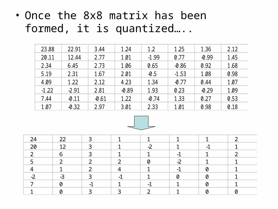
Rate control and MPEG1
• Although MPEG1 is for storage, rate control is possible in certain software packages/modifications
• Techniques to increase code rate• Increase quantizer step size to reduce picture quality
• B frame quality is reduced first to reduce net error– No other frame depends on a B frame

MPEG Audio Compression
• First developed to compress 1.5 Mbits/sec (normal uncompressed audio stream) into 56 kbits/sec (the rate of a basic dialup modem)
• Can encode mono, stereo, and joint-stereo audio
• Designed for generic waveforms (not partial to speech)
• Many different standard sampling rates:
• 16kHz, 22.05kHz, 24kHz, 32 kHz, 44.1 kHz, 48 kHz
• Uses sub-band filtering
• 32 filter bands for layers I and II
• 32 filter bands and 18 sub-bands for layer III (576 bands total)
• Each is equidistant in bandwidth (width = Fs / 64)

Layers of MPEG Audio• Layer I
• 12 samples per sub-band (384 total samples)
• Compression ratio: approx 4:1
• Around 384kbps (depends on chosen sampling rate)
• Layer II
• 36 samples per sub-band (1152 total samples)
• Compression ratio: approx 6:1 to 8:1
• Around 256kbps to 192kbps
• Layer III
• 12 samples per sub-band (384 total samples)
• Compression ratio: approx 10:1 to 12:1

Perceptual Coding and Psychoacoustics
• Similar concept to MPEG interframe coding: irrelevancy is identified and then removed – This is called auditory masking
• Input signal is quantized according to a level that meets both bitrate and masking requirements
• DFT of the input is taken, masking takes place on several levels

Two major types of masking take place for encoding:
• Temporal Masking: loud noises that occur close to each other in time (about 3 to 5 milliseconds) can be approximated by a single loud noise
• Frequency Masking: areas of the spectrum that have high energy and are close together can be filtered to eliminate “spikes” in the spectrum

Human Perception• Smallest signal perception is 0dB (JBN)• Largest signal perception is about 135dB (threshold of
pain) Dynamic range of about 5,000,000 to 1 (ratio of largest
signal to smallest signal)

0
10
20
30
40
50
60
70
80
90
0 2000 4000 6000 8000 10000 12000 14000 16000 18000 20000
Frequency
Am
plit
ud
e
Normal Spectrum

0
10
20
30
40
50
60
70
80
90
0 2000 4000 6000 8000 10000 12000 14000 16000 18000 20000
Frequency
Am
plit
ud
e
Auditory Masking Spectrum

Encoding model for Layer I
=========
========
==
==
==
==
=

MPEG1 Audio Encoding Process
1. Break the signal into frames (a frame is usually several milliseconds in length)
2. Determine spectral energy distribution by taking the DFT, then break this distribubtion into sub-bands via filtering
3. Consider the specified bit rate (this will determine the number of bits per frame that can be used)
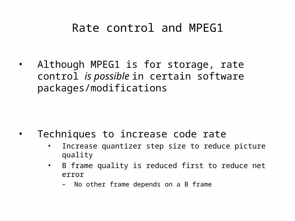
4. Compare the DFT signal to the human psychoacoutic model, perform masking
5. Use a modified Huffman code to achieve compression
6. After each frame has been compressed, place a header on each frame
7. Reassemble the new frames with headers back into a continuous bit stream

MPEG1 Audio is Used:
• In CD format (first intentions were for the CD)
• VCD and DVD formats (even though MPEG1 picture format is obsolete for these kinds of media)
• As a basis for AAC audio (AAC was modeled to rival MPEG2 audio, AAC is considered to be superior to MP3 audio)
• MPEG1 layers I and II were based off of Sony MUSICAM technology

Primary References:
1. http://www.MPEG.org
2. Sayood, Khalid. Introduction to Data Compression, 2nd Edition. 2000, Morgan Kaufmann Publishers: San Diego.
3. Berkely Multimedia Research Center
http://www.bmrc.berkely.edu