mpc unit 1
45
Unit 1 MOBILE NETWORKS 1.CELLULAR WIRELESS NETWORK INTRODUCTION TO CELLULAR NETWORK Cellular network or mobile network is a radio network scattered over land areas called cells. A cell is a coverage of base station connected to other stations via wire or fibre or wirelessly through switching centre. Cellular network employ Space division multiplexing (SDM). Cellular network consist of Cellular Base station. Mobile telephone switching offices (MTSO). Mobile communication devices. Base station: Each cell is served by at least one fixed-location transceiver, known as a cell site or base station. It contains a radio transceiver and controller and provides radio communication to mobile units located in cell. Mobile telephone switching offices (MTSO): The MTSO links calls together using traditional copper, fiber optic, or microwave technology. It also allows mobile communication devices in the cell to dial out and alerts devices in the cell of incoming calls. The MTSO monitors the quality of the communications signal and transfers the call to another base station which is better suited to provide communication to the mobile device. Mobile communication devices: The mobile communication devices consist of hand held phones, car phones, notebook computers, palm-top computers, and portable data collection devices. When these mobile units communicate to the network, they must register with the system by subscribing to a carrier service. If the cell size is preferred as circle, then a overlap and gap occurs. The cell which gives the actual radio coverage is called footprint of a cell. It might so happen that either there may be an overlap between any two such side by side circles or there might be a gap between the coverage areas of two adjacent circles. In a cellular radio system, a land region to be supplied with radio service is divided into regular shaped cells, even though hexagonal cells are conventional. A regular shape for cellular design over a territory which can be served by 3 regular
description
mobile and pervasive computing
Transcript of mpc unit 1

Unit 1
MOBILE NETWORKS
1.CELLULAR WIRELESS NETWORK
INTRODUCTION TO CELLULAR NETWORK
Cellular network or mobile network is a radio network scattered over land
areas called cells. A cell is a coverage of base station connected to other stations
via wire or fibre or wirelessly through switching centre. Cellular network employ
Space division multiplexing (SDM). Cellular network consist of
Cellular Base station.
Mobile telephone switching offices (MTSO).
Mobile communication devices.
Base station: Each cell is served by at least one fixed-location transceiver,
known as a cell site or base station. It contains a radio transceiver and controller
and provides radio communication to mobile units located in cell.
Mobile telephone switching offices (MTSO): The MTSO links calls together
using traditional copper, fiber optic, or microwave technology. It also allows
mobile communication devices in the cell to dial out and alerts devices in the cell
of incoming calls. The MTSO monitors the quality of the communications signal
and transfers the call to another base station which is better suited to provide
communication to the mobile device.
Mobile communication devices: The mobile communication devices consist of
hand held phones, car phones, notebook computers, palm-top computers, and
portable data collection devices. When these mobile units communicate to the
network, they must register with the system by subscribing to a carrier service.
If the cell size is preferred as circle, then a overlap and gap occurs. The cell
which gives the actual radio coverage is called footprint of a cell. It might so
happen that either there may be an overlap between any two such side by side
circles or there might be a gap between the coverage areas of two adjacent circles.
In a cellular radio system, a land region to be supplied with radio service is
divided into regular shaped cells, even though hexagonal cells are conventional. A
regular shape for cellular design over a territory which can be served by 3 regular

WWW.VIDYARTHIPLUS.COM V+ TEAM
polygons, namely, equilateral triangle, square and regular hexagon, which can
cover the entire area without any overlap and gaps.
Along with its regularity, a cell must be designed such that it is most
reliable too, i.e., it supports even the weakest mobile with occurs at the edges of
the cell. For any distance between the center and the farthest point in the cell from
it, a regular hexagon covers the maximum area. In a cellular network, each cell
uses a dissimilar set of frequencies from neighboring cells, to avoid interference
and provide assured bandwidth within each cell.
Fig:1.1 Foot Print of cell showing overlap and gaps
Cell radius differ from tens of meters in buildings, and hundreds of meters
in cities, up to tens of kilometers in the landscape. The set of frequencies can be
reused in other cells, provided that the same frequencies are not reused in adjacent
nearby cells as that would cause co-channel interference.
Fig:1.2 Typical cellular network
FUNDAMENTAL CONCEPT IN CELLULAR TECHNOLOGY
The radio spectrum contains many bands that are allocated and used for
commercial, personal, and military applications. Fifty (50) MHz of spectrum
allocated to cellular networks exists in the 824-849 MHz and the 869-894 MHz
bands (Pagett, 1995). These bands are then further subdivided into 832 channels
allowing many users in the same area to simultaneously access the network. Types
of cellular network access are :
Advanced mobile phone system(AMPS).
Time division multiple access(TDMA).
Code division multiple access(CDMA).
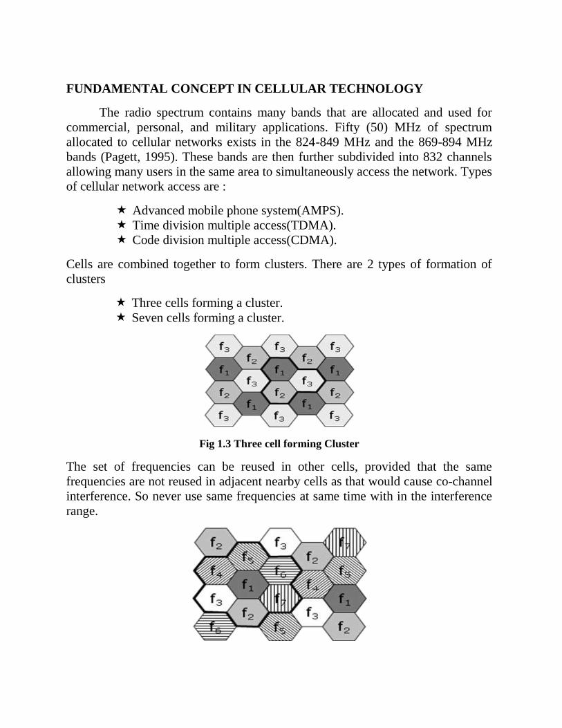
Cells are combined together to form clusters. There are 2 types of formation of
clusters
Three cells forming a cluster.
Seven cells forming a cluster.
Fig 1.3 Three cell forming Cluster
The set of frequencies can be reused in other cells, provided that the same
frequencies are not reused in adjacent nearby cells as that would cause co-channel
interference. So never use same frequencies at same time with in the interference
range.
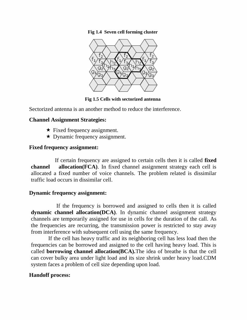
Fig 1.4 Seven cell forming cluster
Fig 1.5 Cells with sectorized antenna
Sectorized antenna is an another method to reduce the interference.
Channel Assignment Strategies:
Fixed frequency assignment.
Dynamic frequency assignment.
Fixed frequency assignment:
If certain frequency are assigned to certain cells then it is called fixed
channel allocation(FCA). In fixed channel assignment strategy each cell is
allocated a fixed number of voice channels. The problem related is dissimilar
traffic load occurs in dissimilar cell.
Dynamic frequency assignment:
If the frequency is borrowed and assigned to cells then it is called
dynamic channel allocation(DCA). In dynamic channel assignment strategy
channels are temporarily assigned for use in cells for the duration of the call. As
the frequencies are recurring, the transmission power is restricted to stay away
from interference with subsequent cell using the same frequency.
If the cell has heavy traffic and its neighboring cell has less load then the
frequencies can be borrowed and assigned to the cell having heavy load. This is
called borrowing channel allocation(BCA).The idea of breathe is that the cell
can cover bulky area under light load and its size shrink under heavy load.CDM
system faces a problem of cell size depending upon load.
Handoff process:
G
Typewritten Text
G
Typewritten Text
WWW.VIDYARTHIPLUS.COM
WWW.VIDYARTHIPLUS.COM V+ TEAM
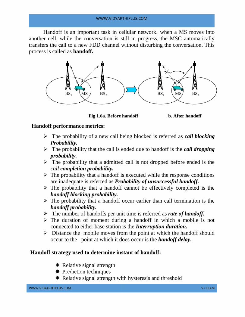
Handoff is an important task in cellular network. when a MS moves into
another cell, while the conversation is still in progress, the MSC automatically
transfers the call to a new FDD channel without disturbing the conversation. This
process is called as handoff.
Fig 1.6a. Before handoff b. After handoff
Handoff performance metrics:
The probability of a new call being blocked is referred as call blocking
Probability. The probability that the call is ended due to handoff is the call dropping
probability. The probability that a admitted call is not dropped before ended is the
call completion probability.
The probability that a handoff is executed while the response conditions
are inadequate is referred as Probability of unsuccessful handoff.
The probability that a handoff cannot be effectively completed is the
handoff blocking probability.
The probability that a handoff occur earlier than call termination is the
handoff probability.
The number of handoffs per unit time is referred as rate of handoff.
The duration of moment during a handoff in which a mobile is not
connected to either base station is the Interruption duration.
Distance the mobile moves from the point at which the handoff should
occur to the point at which it does occur is the handoff delay.
Handoff strategy used to determine instant of handoff:
Relative signal strength
Prediction techniques
Relative signal strength with hysteresis and threshold
WWW.VIDYARTHIPLUS.COM
WWW.VIDYARTHIPLUS.COM V+ TEAM
Relative signal strength with hysteresis
Relative signal strength with threshold
Frequency reuse:
Frequency reuse, or, frequency planning, is a technique of reusing
frequencies and channels within a communication system to improve capacity and
spectral efficiency.
The characteristic of a cellular network is the ability to re-use frequencies to
increase both coverage and capacity. Adjacent cells must use different frequencies
to avoid interference, however there is no difficult with two cells sufficiently far
apart in use on the same frequency. 10 to 50 frequencies are assigned to each cell.
The elements that determine frequency reuse are the reuse distance and the reuse
factor. The reuse distance, D is calculated as
R Cell radius and N- number of cells per cluster.
The rate at which the same frequency can be used in the network is called
frequency reuse factor. It is 1/K
K Number of cells which cannot use the same frequencies for
transmission.
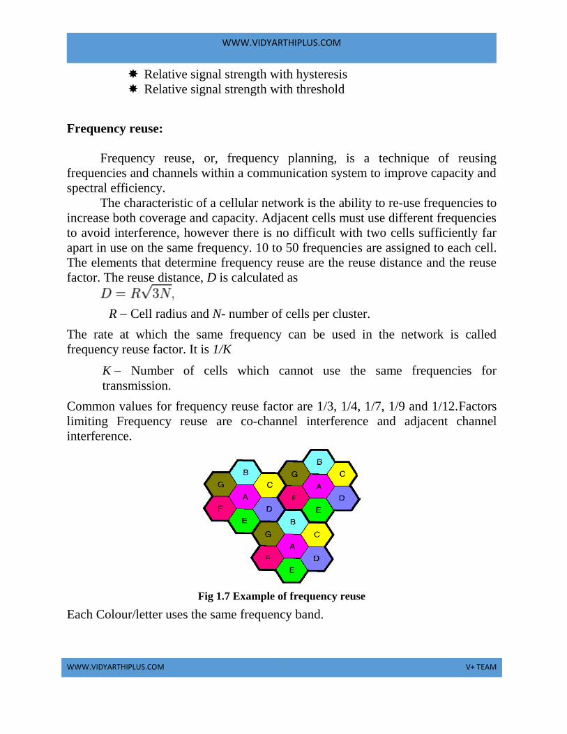
Common values for frequency reuse factor are 1/3, 1/4, 1/7, 1/9 and 1/12.Factors
limiting Frequency reuse are co-channel interference and adjacent channel
interference.
Fig 1.7 Example of frequency reuse
Each Colour/letter uses the same frequency band.

WWW.VIDYARTHIPLUS.COM
WWW.VIDYARTHIPLUS.COM V+ TEAM
ADVANTAGES OF CELLULAR SYSTEMS WITH MINIATURE CELLS
1. Higher capacity: If SDM is employed it allows frequency reuse. If two
transmitter is far away then frequency reuse is possible. If the cell is
small, then more number of
users are allowed.
2. Less transmission power: A mobile or hand held devices needs more
power. The devices which are closer to Base station needs less power for
transmission.
3. Local interference: If there is a large distance between sender and
receiver then there will be more interference. If the cell size is small then
mobile station and base station need to deal with local interference.
4. Robustness: The cellular systems are decentralized. If one antenna fails
it will affect small region.
LIMITATIONS:
1. Infrastructure needed: Complex infra structure is needed to connect
all base station which include antenna, switches, location register which
make the system expensive.
2. Handover needed: Handling over the mobile from one cell to another
if the signal strength decreases when the mobile station moves far away
from BTS. If the cell size is small, then handover take place.
3. Frequency planning: Frequencies have to be distributed carefully to
avoid interference between transmitter using same frequencies. Limited
number of frequencies are available hence interference should be
avoided.
CELLULAR OPERATION:
Cellular network organization uses low power transmitter(100W or
less).The areas are divided into cells. Each cell is served by its own antenna and a
base station consisting of transmitter, receiver, and control unit.
There are three basic devices they are:
A mobile station(MS)
A base transceiver Station(BS)
A Mobile Telecommunications Switching Office
(MTSO)
Base station include an antenna, a controller, and a number of receivers.

WWW.VIDYARTHIPLUS.COM
WWW.VIDYARTHIPLUS.COM V+ TEAM
Base station is at center of each cell. Base station is connected to MTSO. One
MTSO serve as multiple Base station. The link between MTSO to BS is by wire
or wireless.MTSO connects calls between mobile units and from mobile to fixed
telecommunications network .It assigns voice channel and performs handoffs and
monitors calls (billing).
Two channels are available between mobile unit and BS, they are:
1. Control channel: They are used to exchange information and perform
setup and maintaining calls. It establishes a relationship between
Mobile unit and nearest BS.
2. Traffic channel: It carries voice or data connection between users.
Public Land Mobile Network (PLMN) refer to a cellular network that has
land and radio based sections.
Fig 1.8 Overview of cellular network
This network consist of:
Mobile station (MS) is a device used for communication over the
network.
Base station transceiver (BST) is a transmitter/receiver that are used to
transmit/receive signals over the network.
Mobile switching center (MSC) is used to Sets up and maintain calls
made over the network.
Base station controller (BSC) which provides a Communication
between a group of BSTs and a single MSC is controlled by the BSC
Public switched telephone network (PSTN) Consist of Section of the
network that is land base.

WWW.VIDYARTHIPLUS.COM
WWW.VIDYARTHIPLUS.COM V+ TEAM
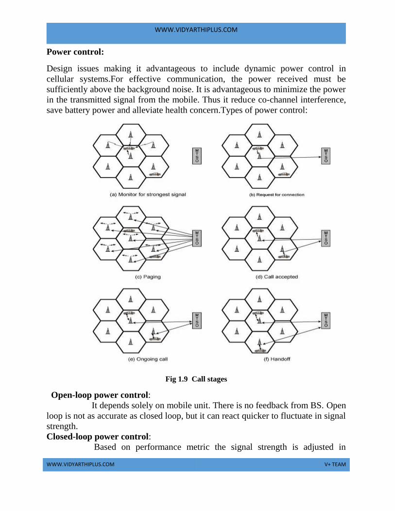
Steps in MTSO controlled call connecting mobile units:
1. Mobile unit initialization scans and choose strongest set up control
channel and automatically pick up a BS antenna of cell. Handshake is
used to spot user and register location. Scan is recurring to allow for
movement of change of cell.
2. Mobile originated call check if the set up channel is free and Send
number on pre-selected channel.
3. In Paging MTSO attempts to connect to mobile unit. Depending on
called mobile number the paging message will be sent to BSs. By
using the setup channel Paging signal is transmitted.
4. In call accepted, the Mobile unit recognizes the number on the set up
channel and responds to BS which in turn send response to MTSO.
Then the MTSO sets up a circuit between calling and called BSs and
select a available traffic channel within cells and notifies BSs. The
BSs notify mobile unit of channel.
5. In Ongoing call the Voice/data is exchanged through respective BSs
and MTSO.
6. If the signal strength decreases as the mobile moves out of range
from BTS it is called handoff. And the traffic channel changes to the
one assigned to new BS.
Other Functions:
1. Call blocking: On mobile-initiated call stage, if all the traffic
channels are busy, the mobile tries again and again. After numeral
retries, a busy tone will be returned.
2. Call termination: The User will hang up, MTSO is informed and the
traffic channels at two BSs are released.
3. Call drop: If the BS cannot maintain a required signal strength then
call drop will occur and the traffic channel is dropped and MTSO
informed.
4. Calls to/from fixed and remote mobile subscriber: Here the MTSO
connects to PSTN and can connect to mobile user and fixed
subscriber via PSTN. MTSO can also connect to remote MTSO via
PSTN or via dedicated line.
Mobile Radio Propagation Effects: Signal strength between BS and mobile
unit is strong enough to maintain signal quality at the receiver. Signal propagation
effects may interrupt the signal and causes error. This is called fading.
WWW.VIDYARTHIPLUS.COM
WWW.VIDYARTHIPLUS.COM V+ TEAM
Power control:
Design issues making it advantageous to include dynamic power control in
cellular systems.For effective communication, the power received must be
sufficiently above the background noise. It is advantageous to minimize the power
in the transmitted signal from the mobile. Thus it reduce co-channel interference,
save battery power and alleviate health concern.Types of power control:
Fig 1.9 Call stages
Open-loop power control:
It depends solely on mobile unit. There is no feedback from BS. Open
loop is not as accurate as closed loop, but it can react quicker to fluctuate in signal
strength.
Closed-loop power control:
Based on performance metric the signal strength is adjusted in

WWW.VIDYARTHIPLUS.COM
WWW.VIDYARTHIPLUS.COM V+ TEAM
reverse channel.BS makes power tuning decision and communication to mobile
on control channel.
Traffic Engineering:
Traffic engineering is a method of optimizing the performance of
a telecommunication network by vigorously analyzing, predicting and regulating
the behavior of data transmitted over that network. Traffic engineering is also
known as tele traffic engineering and traffic management. The method of traffic
engineering can be applied to networks of all kinds, together with
the PSTN (public switched telephone network), LANs (local area
networks), WANs (wide area networks), cellular telephone networks, proprietary
business and the Internet .For N simultaneous user capacity and L subscribers
L < N – non-blocking system, L > N – blocking system.
Traffic Intensity:
Load accessible to a system:
Where
-mean rate of calls attempted per unit time
h -mean holding time per successful call
A -average number of calls arriving during average holding period, for
normalized
2.GSM
INTRODUCTION
GSM was formally known as Groupe Speciale Mobile (found
in1982) and now it is abbreviated as Global System for mobile communications. It
is a standard set developed by the European Telecommunications Standards
Institute (ETSI) to describe protocols for second generation (2G) digital cellular
networks used by mobile phones. It became the de facto global standard for
mobile communications with over 80% market share. The GSM standard was
developed as a replacement for first generation (1G) analog cellular networks, and
originally described a digital, circuit switched network optimized for full duplex
A= h

WWW.VIDYARTHIPLUS.COM
WWW.VIDYARTHIPLUS.COM V+ TEAM
voice telephony. Further improvements were made when the 3GPP developed
third generation (3G) UMTS standards followed by fourth generation (4G) LTE
Advanced standards.
The primary goal of GSM was to provide a mobile
phone system that allows user to roam throughout Europe and provides voice
services compatible to ISDN and other PSTN systems. GSM has initially been
deployed in Europe using 890-915MHz for uplinks and 935-960 for downlinks.
GSM 1800: Otherwise called as Digital cellular Systems DCS 1800
Uplink1710 to 1785 MHz
Downlink 1805 to 1880 MHz
GSM 1900 : Otherwise called as Personal Communication Service PLS
1900
Uplink 1850 to 1910 MHz
Downlink 1930 to 1990 MHz
GSM 400: Uplink 450.4 to 478 MHz
Downlink 460 to 496 MHz
GSM Rail is used in European Countries and railroad systems.
FEATURES OF GSM RAIL
It offers 19 exclusive channels for voice and data traffic. The
special features like emergency calls, voice group call service etc. are
available. Calls are prioritized. Mostly used to control the trains, switches,
signals, gates.
GSM SERVICES
GSM allows the integration of voice and data services and also the
internetworking with the existing network.
There are three types of services offered by GSM

WWW.VIDYARTHIPLUS.COM
WWW.VIDYARTHIPLUS.COM V+ TEAM
Bearer Service
Tele Service
SupplementaryService
REFERENCE MODEL FOR GSM SERVICES
Fig 2.1 GSM services
EXPLANATION:
A mobile station MS is connected to the GSM public land
mobile network PLMN via Um interface. PLMN is the infrastructure needed for
the GSM networks. This network is connected to transit
networks(eg.)PSTN,ISTN,etc. There will be additional network the source/
destinations network before another terminal TE is connected.
BEARER SERVICES:
Bearer Services comprises of all the services that enables the
transparent transmission of data between the interface to the network. It permits
transparent/non transparent , synchronous and asynchronous data transmission.
WWW.VIDYARTHIPLUS.COM
WWW.VIDYARTHIPLUS.COM V+ TEAM
TRANSPARENT BEARER SERVICES:
This services uses the functions of physical layer to transmit data.
Data transmission has a constant delays and throughout if no error occurs but not
in real time. FEC is used to increase the transmission quality. It does not try to
recover the lost data in case of handover.
NON TRANSPARENT BEARER SERVICES:
It uses the protocols of layers data link and network to transmit data.
These services uses transparent bearer service radio link protocol (RLP). RLP has
mechanisms of high level data link control HDLC. It allows retransmission of
erroneous data by using elective reject mechanisms.
TELE SERVCIES:
Tele services are application specific and need all the 7 layers of
ISO/OSI reference model. Services are specified end to end. There tele services
are voice oriented tele service. They are encrypted voice transmission, message
services and data communication with terminals from PSTN/ISDN.
There are some important services:
Telephony services: It has high quality digital voice transmission.
Emergency Number: Mandatory service for all service providers. Its of free
of charge. This connection has the highest priority with pre-emption.
Short Message Service: It is used fro simple message transfer with the
maximum of 160 characters. SMS does not use the standard data channels
of GSM uses the signaling channels. Sending andg receiving SMS is
possible during the data/ voice transmission.
Enhanced Message Service : It is used for large message size with 760
characters, animated pictures, small images can be transmitted.
Multimedia Message Service : It is used to transmit large pictures of GIF/
JPEG , video clips.
Group 3 fax : Fax data is transmitted as digital data over analog telephone
network using modem.
SUPPLEMENTARY SERVICES:
User Identification

WWW.VIDYARTHIPLUS.COM
WWW.VIDYARTHIPLUS.COM V+ TEAM
Call Redirecting / Forwarding
Closed User Group
Multiparty communication
GSM ARCHITECTURE
The architecture of GSM comes in hierarchy, consisting of many
entities, interfaces and subsystems.
The GSM system consist of three subsystems namely,
The Radio Subsystems(RSS)
Network and Switching Subsystems(NSS)
Operation Subsystem(OSS)
The customer is able to notice few components of the network viz. Mobile
Station and Antenna of the Base Transceiver Station(BTS). Remaining
entities are not visible.
1.RADIO SUBSYSTEM:
As the name implies, the radio subsystem (RSS) comprises all
radio specific entities. i.e. the mobile stations(MS) and the base station
subsystem(BSS).

WWW.VIDYARTHIPLUS.COM
WWW.VIDYARTHIPLUS.COM V+ TEAM
Fig 2.2 GSM Architecture
As they are in same frequency they form a cell . The components
of RSS are
Mobile station
Base Transceiver Station
Base Station Subsystem
Base Station Controller
MOBILE STATION: (MS)
MS has all user equipment and software needed for mobile
communications. It has user independent hardware and software. Subscriber
Identity Module (SIM) stores all user specific data. Mobile Station can be
identified as International Mobile equipment identity (IMEI). The sim card
constitutes of Personal Identity number(PIN), PIN unlocking key(PUK),
WWW.VIDYARTHIPLUS.COM
WWW.VIDYARTHIPLUS.COM V+ TEAM
Authentication key k, International Mobile subscriber identity (IMSI). It also has
Identifiers and tables. The current location of MS is found using Temporary
Mobile Subscriber Identity(TMSI) . With TMSI and Location Area Identification
(LAI) the current location can be identified.
BASE TRNSCEIVER STATION: (BTS)
BTS contains the equipment for transmitting and receiving of
radio signals,antennas and equipment for encrypting and decrypting
communications with the Base station controller(BSC). A BTS is controlled by ap
parent BSC via the base station control function(BSCF). The BCF is
implemented as a discrete unit or even incorporated in a TRX in compact base
stations. The BCF provides an operations and maintenance (O&M) connection to
the Network Management System(NMS)and manage operational state of each
TRX as well as soft handling and alarm collection.
The function of BTS vary depending on the cellular technology used
and cellula telephone provider. There are vendors in which the BTS is a plain
transceiver which receives information from MS through Um(Air Interface) and
then it converts into TDM based interface, the Abis and it sends it towards the
BSC. A GSM cell can measure between some 100m and 35km depending on the
environment.
BASE STATION SUBSYSTEM: (BSS)
The base station subsystem is the section of traditional cellular
telephone network which is responsible for handling traffic and signaling between
a mobile phone and the network switching subsystem. The BSS carries out
transcoding of speech channels, allocation of radio channels to mobile phones,
paging, quality management of transmission and reception over the Air interface
and many other tasks related to the radio network.
BASE STATION CONTROLLER : (BSC)
The BSC basically manages the BTSs. It reverses radio frequencies
and handles the handover from one BTS to another within BSS, and performs
paging of the MS. The BSC also multiplexes the radio channels onto the fixed
network connections at A interface.
b) NETWORK AND SWITCHING SUBSYSTEM:
This network and switching subsystem is the heart of GSM. Their
function are to connect wireless network with standard public network, performs
WWW.VIDYARTHIPLUS.COM
WWW.VIDYARTHIPLUS.COM V+ TEAM
handover between different BSS, localization (to locate the mobile
station),Charging, Accounting and roaming of users.The NSS contains the
following switches and databases.
MOBILE SERVIES SWITCHING CENTER(MSC):
MSC are digital ISDN switches. It establishes connection qith
other MSC and BSC via A interfacet Gateway MSC connects to fixed
networks(eg.) PSTN, ISDN. With the help of Internet Working Functions, MSC
can connect to public data Network PDN. It handles all signaling needed for
connection setup, connection release and handover.
HOME LOCATION REGISTER : (HLR)
It is an important database. It stores user relevant information and also
has static information and dynamic information.
Static Information:
Mobile subscriber ISDN number is available. It has subscribed
services for a particular number. It is also an international mobile subscriber
identity.
Dynamic Information :
It is a current location area(LA) of MS. It consist of Mobile
subscriber roaming number (MSRN), VLR and MSC in it. When MS leaves the
current LA, then the information is updated in HLR. The Usage of the information
is to locate the user.
VISITOR LOCATION REGISTER: (VLR)
The VLR is associated to each MSC. It is a dynamic database. It
stores all the information needed for the MS currently in LA. If new MS comes to
LA then the VLR is responsible for copying the information needed from HLR.
c) OPERATION SUBSYSTEM :
The third part of a GSM system is operation subsystem (OSS) which
contains the necessary functions for network operation and maintenance. The OSS
possesses network entities of its own and accesses other entities via SS7 signaling.
The following entities have been defined:

WWW.VIDYARTHIPLUS.COM
WWW.VIDYARTHIPLUS.COM V+ TEAM
OPERATION AND MAINTENANCE CENTER (OMC):
The OMC monitors and controls all other network entities via the
O interface (SS7 with X.25). Typical OMC management functions are traffic
monitoring, status reports of network entities, subscriber and security
management, or accounting and billing. OMCs use the concept of
telecommunication management network (TMN) as standardized by the ITU-T.
Authentication centre (AuC): As the radio interface and mobile stations are
particularly vulnerable, a separate AuC has been defined to protect user identity
and data transmission. The AuC contains the algorithms for authentication as well
as the keys for encryption and generates the values needed for user authentication
in the HLR.
EQUIPMENT IDENTITY REGISTER (EIR):
The EIR is a database for all IMEIs, i.e., it stores all device
identifications registered for this network. As MSs are mobile, they can be easily
stolen. With a valid SIM, anyone could use the stolen MS. The EIR has a blacklist
of stolen (or locked) devices. In theory an MS is useless as soon as the owner has
reported a theft. Unfortunately, the blacklists of different providers are not usually
synchronized and the illegal use of a device in another operator‟s network is
possible (the reader may speculate as to why this is the case). The EIR also
contains a list of valid IMEIs (white list), and a list of malfunctioning devices
(gray list).
GSM PROTOCOL SUITES :
The layers are
PHYSICAL LAYER:
The physical layer handles all radio specific functions.
Functions :
1. Creation of burst in any one of 5 format.
WWW.VIDYARTHIPLUS.COM
WWW.VIDYARTHIPLUS.COM V+ TEAM
2. Multiplexing burst into a TDMA frame.
3. Synchronization with BTS.
4. Detection of idle channel.
5. Channel Quality measurement.
6. Channel coding and error detection and correction.
The Um interfaces use GMSK for modulation and perform encryption and
decryption.
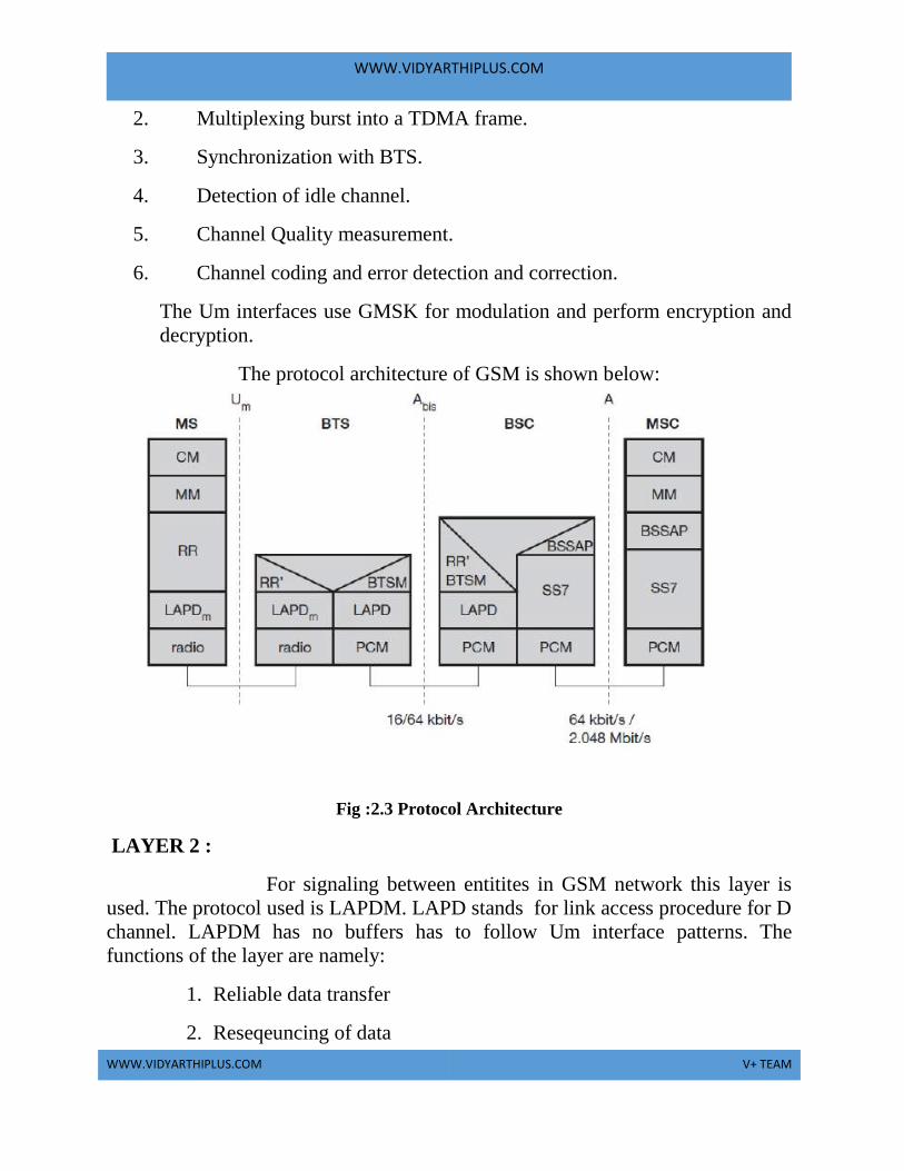
The protocol architecture of GSM is shown below:
Fig :2.3 Protocol Architecture
LAYER 2 :
For signaling between entitites in GSM network this layer is
used. The protocol used is LAPDM. LAPD stands for link access procedure for D
channel. LAPDM has no buffers has to follow Um interface patterns. The
functions of the layer are namely:
1. Reliable data transfer
2. Reseqeuncing of data

WWW.VIDYARTHIPLUS.COM
WWW.VIDYARTHIPLUS.COM V+ TEAM
3. Flow control
LAYER 3 : NETWORK LAYER
The network layer has sublayers. They are,
1. RADIO RESOURCE MANAGEMENT:
This is the lowest sub layer and it’s a part of RR and RR’ is
implemented by BSC. The function of RR are Setup, Maintenance, Release of
radio channels. RR directly access the physical layer. It supports BTS
management. The function of RR’ are supported by BSC via BSTM.
2. MOBILITY MANAGEMENT:
The main function of Mobility management are Registration,
Authentication, Identification, Location Updating, Providing TMSI, IMSI.
LAYER 4 : CALL MANAGEMENT:
This layer contains three entities. They are Call control, SMS,
Supplementary services. Call control provides point to point connection between
two terminals and also used for call clearance, change of call parameters. SMS
allows messages transfer using control channels. The supplementary services
discussed already is to be reproduced here.
CONNECTION ESTABLISHMENT:
The number dialed to reach a mobile subscriber (MSISDN) contains
no information at all about the current location of the subscriber. In order to
establish a complete connection to a mobile subscriber, however, one must
determine the current location and the locally responsible switch (MSC). In order
to be able to route the call to this switch, the routing address to this subscriber
(MSRN) has to be obtained. This routing address is assigned temporarily to a
subscriber by its currently associated VLR. At the arrival of a call at the GMSC,
WWW.VIDYARTHIPLUS.COM
WWW.VIDYARTHIPLUS.COM V+ TEAM
the HLR is the only entity in the GSM network which can supply this information,
and therefore it must be interrogated for each connection setup to a mobile
subscriber. An ISDN switch recognizes from the MSISDN that the called
subscriber is a mobile subscriber, and therefore can forward the call to the GMSC
of the subscriber's home PLMN based on the CC and NDC in the MSISDN. This
GMSC can now request the current routing address (MSRN) for the mobile
subscriber from the HLR using the MAP . By way of the MSRN the call is
forwarded to the local MSC, which determines the TMSI of the subscriber and
initiates the paging procedure in the relevant location area . After the MS has
responded to the paging call, the connection can be switched through.Several
variants for determining the route and interrogating the HLR exist, depending on
how the MSRN was assigned and stored, whether the call is national or
international and depending on the capabilities of the associated switching centers.
To locate a MS and to address the MS, several numbers are needed:
MOBILE STATION INTERNATIONAL ISDN NUMBER (MSISDN):
The only important number from the user of GSM is phone number.
Remember that the phone number is not associated with certain device but with
the SIM, which is personalized for user. The number consist of country code(CC)
as eg.+49 179 1234567 with 49 for germany. National Destination Code (NDC) is
used to locate the network provider and Subscriber number.
INTERNATIONAL MOBILE SUBSCRIBER IDENTITY(IMSI):
GSM uses the IMSI for internal unique identification of a subscriber. IMSI consist
of a mobile country code (MCC) and mobile network code(MNC) and finally the
mobile subscriber identification number(MSIN).
TEMPORARY MOBILE SUBSCRIBE IDENTITY(TMSI):
To hide the IMSI, which would give away the exact identity of user
signaling over the air interface, GSM uses the 4 byte.TMSI is selected by current
VLR and is only valid temporarily and within location area of VLR.
WWW.VIDYARTHIPLUS.COM
WWW.VIDYARTHIPLUS.COM V+ TEAM
MOBILE STATION ROAMING NUMBER (MSRM):
Another temporary address which hides the identity and location of a
subscriber is MSRN. The VLR generates this address on request from MSC, and
the address is stored in the HLR . MSRN contains current visitory and visitor
national destination code(VNDC).
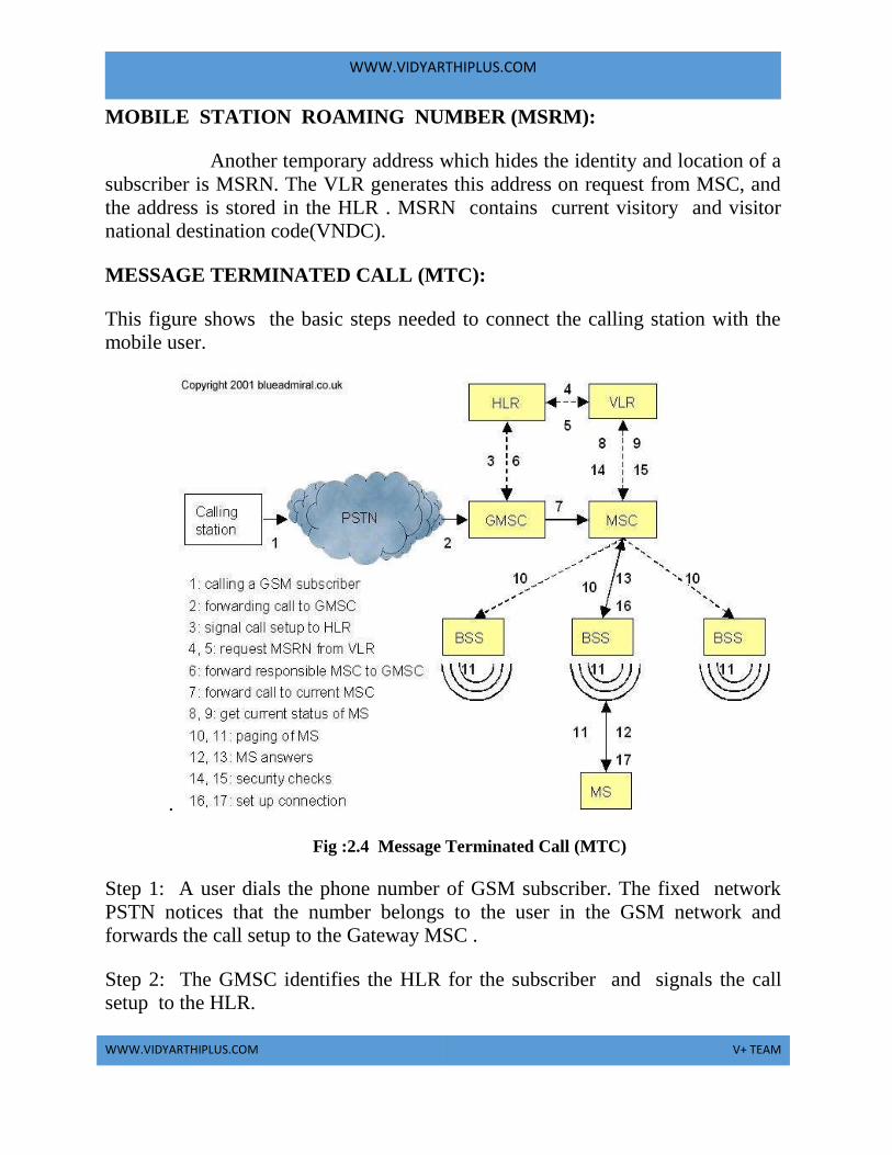
MESSAGE TERMINATED CALL (MTC):
This figure shows the basic steps needed to connect the calling station with the
mobile user.
.
Fig :2.4 Message Terminated Call (MTC)
Step 1: A user dials the phone number of GSM subscriber. The fixed network
PSTN notices that the number belongs to the user in the GSM network and
forwards the call setup to the Gateway MSC .
Step 2: The GMSC identifies the HLR for the subscriber and signals the call
setup to the HLR.
WWW.VIDYARTHIPLUS.COM
WWW.VIDYARTHIPLUS.COM V+ TEAM
Step 3: The HLR now checks whether the number exists and whether the user has
subscribed to the requested services, and the requests an MSRN from the current
VLR.
Step 4 : After receiving the request from MSRN
Step 5 : HLR can determine the MSC responsible for the MS and forwards this
information to GMSC
Step 6 : GMSC can now forward the call setup request to MSC indicated.
Step 7: From this, MSC is responsible for all further steps. First it requests the
current status of MS from VLR.
Step 8 : If MS is available, then MSC initiates paging in all cells it is responsible
for as searching for the right cell would be too time consuming.
Step 9: This approach puts some load on signalling channels so optimization
exist.
Step 10 : Location area (LA) can be determined.
Step 11 : The BTSs of all BSSs transmit this paging signal to MS.
Step 12 & 13 : If MS answers ( 12 and 13) the VLR has to perform security
checks set up be encryption techniques.
Steps 14 to 17 : The VLR signals to MSC to setup a connection to MS.
MESSAGE ORIGINATED CALL (MOC):
It is simpler to perform message originated call(MOC)
compared to MTC.

WWW.VIDYARTHIPLUS.COM
WWW.VIDYARTHIPLUS.COM V+ TEAM
Fig 2.5 Message Originated Call (MOC)
The basic steps for MOC are,
Step 1: MS transmits a request for a new connection.
Step 2: BSS forwards the request to MSC.
Steps 3 & 4 : MSC then checks if the user is allowed to set up a call with the
requested service(3 and 4) and checks the availability of resources through GSM
network into PSTN.
Steps 5to 8 : If all resources are available, MSC sets up a connection between MS
and fixed network.
Steps 9 & 10 : Its set up a call with the help of BSS and MS.
MESSAGE FLOW FOR MTC AND MOC :
In addition to the above steps mentioned above , the other
messages are exxchanged between an MS and BTS during connection setup.
These messages can be quite often heard in radios or badly sheileded speakers as
crackling noise before the phone rings. Figure shows the message for an MTC
and MOC. Paging is only necessary for an MTC, then similar message exchanges
follow. The next step which are needed for a communication security
comprises the authentication of MS and switching to encrytpted communication
WWW.VIDYARTHIPLUS.COM
WWW.VIDYARTHIPLUS.COM V+ TEAM
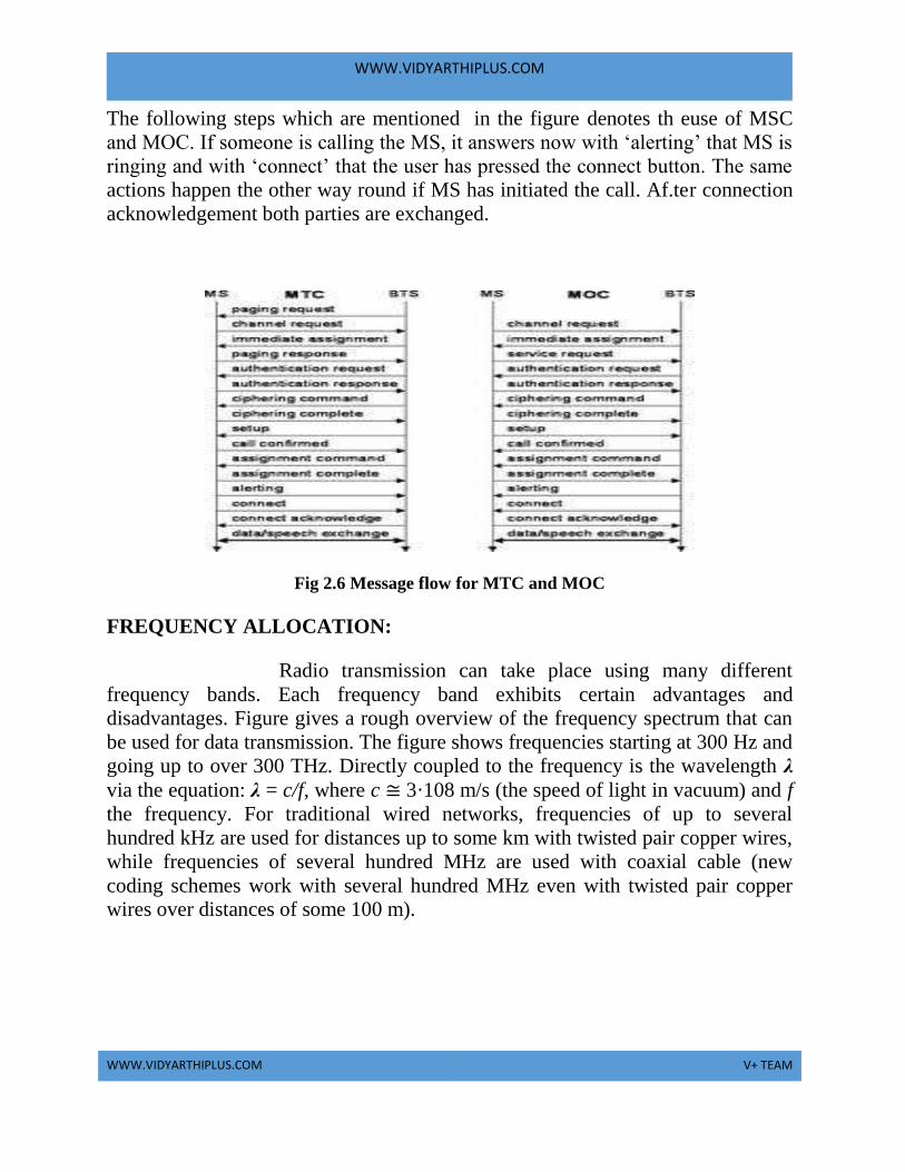
The following steps which are mentioned in the figure denotes th euse of MSC
and MOC. If someone is calling the MS, it answers now with ‘alerting’ that MS is
ringing and with ‘connect’ that the user has pressed the connect button. The same
actions happen the other way round if MS has initiated the call. Af.ter connection
acknowledgement both parties are exchanged.
Fig 2.6 Message flow for MTC and MOC
FREQUENCY ALLOCATION:
Radio transmission can take place using many different
frequency bands. Each frequency band exhibits certain advantages and
disadvantages. Figure gives a rough overview of the frequency spectrum that can
be used for data transmission. The figure shows frequencies starting at 300 Hz and
going up to over 300 THz. Directly coupled to the frequency is the wavelength λ
via the equation: λ = c/f, where c ≅ 3·108 m/s (the speed of light in vacuum) and f
the frequency. For traditional wired networks, frequencies of up to several
hundred kHz are used for distances up to some km with twisted pair copper wires,
while frequencies of several hundred MHz are used with coaxial cable (new
coding schemes work with several hundred MHz even with twisted pair copper
wires over distances of some 100 m).

WWW.VIDYARTHIPLUS.COM
WWW.VIDYARTHIPLUS.COM V+ TEAM
Fig 2.7 Frequency allocation
Fiber optics are used for frequency ranges of several hundred THz,
but here one typically refers to the wavelength which is, e.g., 1500 nm, 1350 nm
etc. (infra red). Radio transmission starts at several kHz, the very low frequency
(VLF) range. These are very long waves. Waves in the low frequency (LF) range
are used by submarines, because they can penetrate water and can follow the
earth‟s surface. Some radio stations still use these frequencies, e.g., between
148.5 kHz and 283.5 kHz in Germany. The medium frequency (MF) and high
frequency (HF) ranges are typical for transmission of hundreds of radio stations
either as amplitude modulation (AM) between 520 kHz and 1605.5 kHz, as short
wave (SW) between 5.9 MHz and 26.1 MHz, or as frequency modulation (FM)
between 87.5 MHz and 108 MHz. The frequencies limiting these ranges are
typically fixed by national regulation and, vary from country to country. Short
waves are typically used for (amateur) radio transmission around the world,
enabled by reflection at the ionosphere
. Transmit power is up to 500 kW – which is quite high compared to
the 1 W of a mobile phone. As we move to higher frequencies, the TV stations
follow. Conventional analog TV is transmitted in ranges of 174–230 MHz and
470–790 MHz using the very high frequency (VHF) and ultra high frequency
(UHF) bands. In this range, digital audio broadcasting (DAB) takes place as well
(223–230 MHz and 1452–1472 MHz) and digital TV is planned or currently being
installed (470– 862 MHz), reusing some of the old frequencies for analog TV.
UHF is also used for mobile phones with analog technology (450–465 MHz), the
digital GSM (890–960 MHz, 1710–1880 MHz), digital cordless telephones
following the DECT standard (1880–1900 MHz), 3G cellular systems following
the UMTS standard (1900–1980 MHz, 2020–2025 MHz, 2110–2190 MHz) and
many more. VHF and especially
UHF allow for small antennas and relatively reliable connections for
mobile telephony. Super high frequencies (SHF) are typically used for directed
WWW.VIDYARTHIPLUS.COM
WWW.VIDYARTHIPLUS.COM V+ TEAM
microwave links (approx. 2–40 GHz) and fixed satellite services in the C-band (4
and 6 GHz), Ku-band (11 and 14 GHz), or Ka-band (19 and 29 GHz). Some
systems are planned in the extremely high frequency (EHF) range which comes
close to infra red. All radio frequencies are regulated to avoid interference, e.g.,
the German regulation covers 9 kHz–275 GHz. The next step into higher
frequencies involves optical transmission, which is not only used for fiber optical
links but also for wireless communications. Infra red (IR) transmission is used
for directed links, e.g., to connect different buildings via laser links. The most
widespread IR technology, infra red data association (IrDA), uses wavelengths of
approximately 850–900 nm to connect laptops, PDAs etc. Finally, visible light has
been used for wireless transmission for thousands of years. While light is not very
reliable due to interference, but it is nevertheless useful due to built-in human
receivers. Powered by
ROUTING :
A satellite system together with gateways and fixed terrestrial
networks as shown in Figure 5.1 has to route data transmissions from one user to
another as any other network does. Routing in the fixed segment (on earth) is
achieved as usual, while two different solutions exist for the satellite network in
space. If satellites offer ISLs, traffic can be routed between the satellites. If not, all
traffic is relayed to earth, routed there, and relayed back to a satellite. Assume two
users of a satellite network exchange data. If the satellite system supports ISLs,
one user sends data up to a satellite and the satellite forwards it to the one
responsible for the receiver via other satellites. This last satellite now sends the
data down to the earth. This means that only one uplink and one downlink per
direction is needed. The ability of routing within the satellite network reduces the
number of gateways needed on earth. If a satellite system does not offer ISLs, the
user also sends data up to a satellite, but now this satellite forwards the data to a
gateway on earth. Routing takes place in fixed networks as usual until another
gateway is reached which is responsible for the satellite above the receiver. Again
data is sent up to the satellite which forwards it down to the receiver. This solution
requires two uplinks and two downlinks. Depending on the orbit and the speed of
routing in the satellite network compared to the terrestrial network, the solution
with ISLs might offer lower latency. The drawbacks of ISLs are higher system
complexity due to additional antennas and routing hard- and software for the
satellites.

WWW.VIDYARTHIPLUS.COM
WWW.VIDYARTHIPLUS.COM V+ TEAM
Fig 2.8 Routing
MOBILITY MANAGEMENT:
Mobility management is one of the major functions of a GSM or a
UMTS network that allows mobile phones to work. The aim of mobility
management is to track where the subscribers are, allowing calls, SMS and other
mobile phone services to be delivered to them. Location update procedure.
A GSM or UMTS network, like all cellular networks, is a radio
network of individual cells, known as base stations. Each base station covers a
small geographical area which is part of a uniquely identified location area. By
integrating the coverage of each of these base stations, a cellular network provides
a radio coverage over a much wider area. A group of base stations is named a
location area, or a routing area.
The location update procedure allows a mobile device to inform
the cellular network, whenever it moves from one location area to the next.
Mobiles are responsible for detecting location area codes. When a mobile finds
that the location area code is different from its last update, it performs another
update by sending to the network, a location update request, together with its
previous location, and its Temporary Mobile Subscriber Identity (TMSI).
There are several reasons why a mobile may provide updated
location information to the network. Whenever a mobile is switched on or off, the
network may require it to perform an IMSI attach or IMSI detach location update

WWW.VIDYARTHIPLUS.COM
WWW.VIDYARTHIPLUS.COM V+ TEAM
procedure. Also, each mobile is required to regularly report its location at a set
time interval using a periodic location update procedure. Whenever a mobile
moves from one location area to the next while not on a call, a random location
update is required. This is also required of a stationary mobile that reselects
coverage from a cell in a different location area, because of signal fade. Thus a
subscriber has reliable access to the network and may be reached with a call,
while enjoying the freedom of mobility within the whole coverage area.
When a subscriber is paged in an attempt to deliver a call or SMS
and the subscriber does not reply to that page then the subscriber is marked as
absent in both the Mobile Switching Center / Visitor Location Register
(MSC/VLR) and the Home Location Register (HLR) (Mobile not reachable flag
MNRF is set). The next time the mobile performs a location update the HLR is
updated and the mobile not reachable flag is cleared.
TMSI
The Temporary Mobile Subscriber Identity (TMSI) is the identity that is most
commonly sent between the mobile and the network. TMSI is randomly assigned
by the VLR to every mobile in the area, the moment it is switched on. The number
is local to a location area, and so it has to be updated each time the mobile moves
to a new geographical area.
The network can also change the TMSI of the mobile at any time. And it normally
does so, in order to avoid the subscriber from being identified, and tracked by
eavesdroppers on the radio interface. This makes it difficult to trace which mobile
is which, except briefly, when the mobile is just switched on, or when the data in
the mobile becomes invalid for one reason or another. At that point, the global
"international mobile subscriber identity" (IMSI) must be sent to the network. The
IMSI is sent as rarely as possible, to avoid it being identified and tracked.
A key use of the TMSI is in paging a mobile. "Paging" is the one-
to-one communication between the mobile and the base station. The most
important use of broadcast information is to set up channels for "paging". Every
cellular system has a broadcast mechanism to distribute such information to a
plurality of mobiles. Size of TMSI is 4 octet with full hex digits and can't be all 1
because the SIM uses 4 octets with all bits equal to 1 to indicate that no valid
TMSI is available.

WWW.VIDYARTHIPLUS.COM
WWW.VIDYARTHIPLUS.COM V+ TEAM
ROAMING
Roaming is one of the fundamental mobility management
procedures of all cellular networks. Roaming is defined as the ability for a
cellular customer to automatically make and receive voice calls, send and receive
data, or access other services, including home data services, when travelling
outside the geographical coverage area of the home network, by means of using a
visited network. This can be done by using a communication terminal or else just
by using the subscriber identity in the visited network. Roaming is technically
supported by mobility management, authentication, authorization and billing
procedures.
LOCATION AREA
A "location area" is a set of base stations that are grouped together to optimise
signalling. Typically, tens or even hundreds of base stations share a single Base
Station Controller (BSC) in GSM, or a Radio Network Controller (RNC) in
UMTS, the intelligence behind the base stations. The BSC handles allocation of
radio channels, receives measurements from the mobile phones, controls
handovers from base station to base station.
To each location area, a unique number called a "location area code"
is assigned. The location area code is broadcast by each base station, known as a
"base transceiver station" BTS in GSM, or a Node B in UMTS, at regular
intervals. In GSM, the mobiles cannot communicate directly with each other but,
have to be channeled through the BTSs. In UMTS networks, if no Node B is
accessible to a mobile, it will not be able to make any connections at all.
If the location areas are very large, there will be many mobiles
operating simultaneously, resulting in very high paging traffic, as every paging
request has to be broadcast to every base station in the location area. This wastes
bandwidth and power on the mobile, by requiring it to listen for broadcast
messages too much of the time. If on the other hand, there are too many small
location areas, the mobile must contact the network very often for changes of
location, which will also drain the mobile's battery. A balance has therefore to be
struck.
ROUTING AREA

WWW.VIDYARTHIPLUS.COM
WWW.VIDYARTHIPLUS.COM V+ TEAM
The routing area is the PS domain equivalent of the location area. A
"routing area" is normally a subdivision of a "location area". Routing areas are
used by mobiles which are GPRS-attached. GPRS is optimized for "bursty" data
communication services, such as wireless internet/intranet, and multimedia
services. It is also known as GSM-IP ("Internet Protocol") because it will connect
users directly to Internet Service Providers (ISP).
The bursty nature of packet traffic means that more paging messages are expected
per mobile, and so it is worth knowing the location of the mobile more accurately
than it would be with traditional circuit-switched traffic. A change from routing
area to routing area (called a "Routing Area Update") is done in an almost
identical way to a change from location area to location area. The main
differences are that the "Serving GPRS Support Node" (SGSN) is the element
involved.
TRACKING AREA
The tracking area is the LTE counterpart of the location area and
routing area. A tracking area is a set of cells. Tracking areas can be grouped into
lists of tracking areas (TA lists), which can be configured on the User equipment.
Tracking area updates are performed periodically or when the UE moves to a
tracking area that is not included in its TA list.
Operators can allocate different TA lists to different UEs. This can avoid signaling
peaks in some conditions: for instance, the UEs of passengers of a train may not
perform tracking area updates simultaneously. On the network side, the involved
element is the Mobility Management Entity.
HANDOVER
Handover means handing over the mobile from one cell to another
cell. There are two reasons for handover.
They are,
(1)
When a mobile station moves out of the range of BTS the signal level
decreases continuously and falls below the minimal requirements for
communication.

WWW.VIDYARTHIPLUS.COM
WWW.VIDYARTHIPLUS.COM V+ TEAM
The error rate increases due to interference.
The quality of radio link decrease.
(2)
The traffic in one cell is too high, shifting of some MS to other cells with
lower load. This is called load balancing.
The number of handover will be more when the cell size is small.
Due to handover the calls should not get to cutoff which is called as call
drop.
TYPES OF HANDOVER :
(1) INTRA CELL HANDOVER:
With in a cell, narrow band interference can cause transmission at a
certain frequency impossible.
The BSC decides to change the carrier frequency.
(2) INTER CELL, INTRA BSC HANDOVER:
The mobile station moves from one cell to another but remains
with in the same BSC.
The BSC performs a handover, assigns a new radio channel in the
new cell and releases the old one.
(3) INTER BSC, INTRA MSC HANDOVER:
The BSC controls only limited cells.
Handover needs to be done between different BSC.
This is controlled by MSC.
(4) INTER MSC HANDOVER:
A handover is needed between 2 cells which belong to difference
MSC.
Both MSC performs the handover together.

WWW.VIDYARTHIPLUS.COM
WWW.VIDYARTHIPLUS.COM V+ TEAM
SECURITY :
GSM offers several security services using confidential
information stored in the AuC and in the individual SIM (which is plugged into an
arbitrary MS). The SIM stores personal, secret data and is protected with a PIN
against unauthorized use. (For example, the secret key Ki used for authentication
and encryption procedures is stored in the SIM.) The security services offered by
GSM are explained below:
● ACCESS CONTROL AND AUTHENTICATION: The first step includes the
authentication of a valid user for the SIM. The user needs a secret PIN to access
the SIM. The next step is the subscriber authentication .
● CONFIDENTIALITY: All user-related data is encrypted. After authentication,
BTS and MS apply encryption to voice, data, and signaling. This confidentiality
exists only between MS and BTS, but it does not exist end-to-end or within the
whole fixed GSM/telephone network.
● ANONYMITY: To provide user anonymity, all data is encrypted before
transmission, and user identifiers (which would reveal an identity) are not used
over the air. Instead, GSM transmits a temporary identifier (TMSI), which is
newly assigned by the VLR after each location update. Additionally, the VLR can
change the TMSI at any time. Three algorithms have been specified to provide
security services in GSM. Algorithm A3 is used for authentication, A5 for
encryption, and A8 for the generation of a cipher key. In the GSM standard only
algorithm A5 was publicly available, whereas A3 and A8 were secret, but
standardized with open interfaces. Both A3 and A8 are no longer secret, but were
published on the internet in 1998. This demonstrates that security by obscurity
does not really work. As it turned out, the algorithms are not very strong.
However, network providers can use stronger algorithms for authentication – or
users can apply stronger end-to-end encryption. Algorithms A3 and A8 (or their
replacements) are located on the SIM and in the AuC and can be proprietary. Only
A5 which is implemented in the devices has to be identical for all providers.
AUTHENTICATION Before a subscriber can use any service from the GSM network, he
or she must be authenticated. Authentication is based on the SIM, which stores the
WWW.VIDYARTHIPLUS.COM
WWW.VIDYARTHIPLUS.COM V+ TEAM
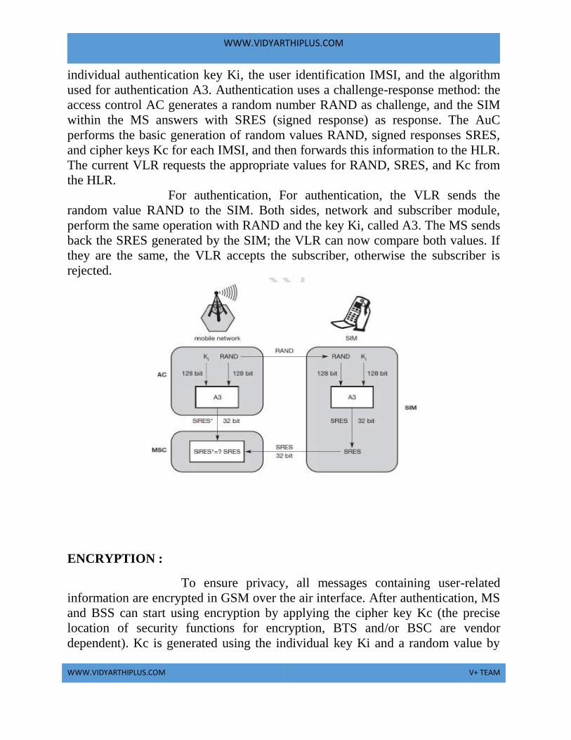
individual authentication key Ki, the user identification IMSI, and the algorithm
used for authentication A3. Authentication uses a challenge-response method: the
access control AC generates a random number RAND as challenge, and the SIM
within the MS answers with SRES (signed response) as response. The AuC
performs the basic generation of random values RAND, signed responses SRES,
and cipher keys Kc for each IMSI, and then forwards this information to the HLR.
The current VLR requests the appropriate values for RAND, SRES, and Kc from
the HLR.
For authentication, For authentication, the VLR sends the
random value RAND to the SIM. Both sides, network and subscriber module,
perform the same operation with RAND and the key Ki, called A3. The MS sends
back the SRES generated by the SIM; the VLR can now compare both values. If
they are the same, the VLR accepts the subscriber, otherwise the subscriber is
rejected.
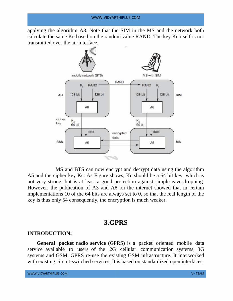
ENCRYPTION :
To ensure privacy, all messages containing user-related
information are encrypted in GSM over the air interface. After authentication, MS
and BSS can start using encryption by applying the cipher key Kc (the precise
location of security functions for encryption, BTS and/or BSC are vendor
dependent). Kc is generated using the individual key Ki and a random value by
WWW.VIDYARTHIPLUS.COM
WWW.VIDYARTHIPLUS.COM V+ TEAM
applying the algorithm A8. Note that the SIM in the MS and the network both
calculate the same Kc based on the random value RAND. The key Kc itself is not
transmitted over the air interface.
MS and BTS can now encrypt and decrypt data using the algorithm
A5 and the cipher key Kc. As Figure shows, Kc should be a 64 bit key which is
not very strong, but is at least a good protection against simple eavesdropping.
However, the publication of A3 and A8 on the internet showed that in certain
implementations 10 of the 64 bits are always set to 0, so that the real length of the
key is thus only 54 consequently, the encryption is much weaker.
3.GPRS
INTRODUCTION:
General packet radio service (GPRS) is a packet oriented mobile data
service available to users of the 2G cellular communication systems, 3G
systems and GSM. GPRS re-use the existing GSM infrastructure. It interworked
with existing circuit-switched services. It is based on standardized open interfaces.
WWW.VIDYARTHIPLUS.COM
WWW.VIDYARTHIPLUS.COM V+ TEAM
GPRS usage is typically charged based on volume of data transferred,
contrasting with circuit switched data, which is usually billed per minute of
connection time. 5 GB per month for a fixed fee or on a pay-as-you-use basis.
Usage above the bundle cap is either charged per megabyte or disallowed.
GPRS is a best effort service, implying variable throughput and latency that
depend on the number of other users sharing the service concurrently, as opposed
to circuit switching, where a certain quality of service (QoS) is guaranteed during
the connection. In 2G systems, GPRS provides data rates of 56–114
kbit/second. 2G cellular technology combined with GPRS is sometimes described
as 2.5G, that is, a technology between the second (2G) and third (3G) generations
of mobile telephony. It provides moderate-speed data transfer, by using
unused time division multiple access (TDMA) channels in, for example, the GSM
system. GPRS is integrated into GSM Release 97 and newer releases.
GPRS provides two services:
1. Point-to-point (PTP)
2. Point-to-multipoint (PTM)
In point-to-point packet delivery service, in which packet is transfer
between two users and in point-to-multipoint (PTM) service, in which packet is
delivering to multiple destinations within one service request.
In PTP versions are PTP Connection oriented Network service (PTP-
CONS), which establish a logical relation in between users. Multiple packets are
sent between single source and a single destination. Other version is the PTP
Connectionless Network Service (PTP-CLNS), which does not require a logical
link between users. Packets are sent between a single source and a single
destination. Each packet is independent of its predecessor and successor.
QoS-profile can be specified by the users of the GPRS. It is maintained in the
PDP context. PDP Context is nothing but which is created in each
communication session. QoS-profile is used to indicate the network and radio
resources required for data transmission. It has the attributes such as service
precedence (high,normal,low),reliability class, delay class, peak throughput class,
mean throughput class. GPRS must allocate radio resources to fulfill these user
specifications. GPRS network is suffered by the following delays such as channel
access delay, coding for error correction and transfer delay in the fixed part and
wireless part of the network. GPRS also includes several security services namely
WWW.VIDYARTHIPLUS.COM
WWW.VIDYARTHIPLUS.COM V+ TEAM
authentication, user identity confidentiality, access control and user information
confidentiality.
Main benefits
Resources are reserved only when needed and charged accordingly.
Connection setup times are reduced. It will enable new service opportunities. It
has High Speed (Data Rate 14.4 – 115 kbps). It uses the efficient radio bandwidth
(Statistical Multiplexing).Circuit switching & Packet Switching can be used in
parallel. It has Constant connectivity.
Characteristics of GPRS:
1. GPRS uses packet switched resource allocation.
2. Flexible channel allocation.
3. Support for leading internet communication protocols.
GPRS Terminal Classes:
1. Class A
It can be connected to GPRS service and GSM service (voice, SMS), using both
at the same time. Such devices are known to be available today.
2. Class B
It can be connected to GPRS service and GSM service (voice, SMS), but using
only one or the other at a given time. During GSM service (voice call or SMS),
GPRS service is suspended, and then resumed automatically after the GSM
service (voice call or SMS) has concluded. Most GPRS mobile devices are Class
B.
3. Class C
They are connected to either GPRS service or GSM service (voice, SMS). Must
be switched manually between one or the other service.
GPRS ARCHITECTURE
In order to understand the GPRS network architecture, some fundamental GSM
terminology is necessary. This section describes some of the main components of
the GSM network.

WWW.VIDYARTHIPLUS.COM
WWW.VIDYARTHIPLUS.COM V+ TEAM
GPRS Networks
GPRS architecture has two network elements, which are called as GPRS
support nodes (GSN).They are,
1. Gateway GPRS Support Node(GGSN)
2. Serving GPRS Support Node (SGSN)
All GSNs are integrated into the standard GSM architecture and many interfaces
(see figure 1). The network elements are gateway GPRS support node (GGSN)
is provisioned by router, which supports traditional gateway functionality. It is the
interworking unit between the GPRS network and external packet data networks
(PDN). This node contains routing information for GPRS users. It performs
address conversion and tunnels data to a user via encapsulation. The GGSN is
connected to external networks (e.g., IP or X.25) via the Gi and transfers packets
to the SGSN via an IP-based GPRS backbone network (Gn interface).
Fig 3.1 GPRS Architecture Reference Model
The other element is the serving GPRS support node (SGSN) which connects
BSS and GGSN. It supports the MS via the Gb interface. It requests the user
address from the GPRS register (GR). It keeps track of the individual MSs’
location, is in charge for collecting billing information. It performs many security
functions.
Packet Control Unit (PCU)
WWW.VIDYARTHIPLUS.COM
WWW.VIDYARTHIPLUS.COM V+ TEAM
The PCU separates the circuit switched and packet switched traffic from
the user and sends them to the GSM and GPRS networks respectively. It also
performs most of the radio resource management functions of the GPRS network.
The PCU can be either located in the BTS, BSC, or some other point between the
MS and the MSC. There will be at least one PCU that serves a cell in which GPRS
services will be available. Frame Relay technology is being used at present to
interconnect the PCU to the GPRS core.
GPRS interfaces
Um between an MS and the GPRS fixed network part. The Um is the access
interface the MS uses to access the GPRS network. The radio interface to the BTS
is the same interface used by the existing GSM network with some GPRS specific
changes.
Gb between a SGSN and a BSS. The Gb interface carries the GPRS traffic and
signaling between the GSM radio network (BSS) and the GPRS network. Frame
Relay based network services is used for this interface.
Gn between two GSNs within the same PLMN. The Gn provides a data and
signalling interface in the Intra-PLMN backbone. The GPRS Tunnelling Protocol
(GTP) is used in the Gn (and in the Gp) interface over the IP based backbone
network.
Mobile Station
A GSM subscriber needs a terminal called Mobile Station (MS). It is used to
connect to the network using the radio interface Um. In idle mode an MS is not
reachable and all contexts will be deleted. In the standby state there is only
movement across routing areas which is updated to the SGSN. Before sending any
data over the GPRS network, an MS must attach to it, following the procedures of
the mobility management. The attachment procedure includes assigning a
temporal identifier, called a temporary logical link identity (TLLI), and a
ciphering key sequence number (CKSN) for data encryption.
GPRS BSS
Base Station Subsystem (BSS) which performs radio-related functions. BSS
contains Base Transceiver Stations (BTS) and Base Station Controllers (BSC).
BTS which provides new GPRS channel coding schemes through Channel
Codec Unit (CCU). The BTS handles the radio interface to the MS. It consists of
WWW.VIDYARTHIPLUS.COM
WWW.VIDYARTHIPLUS.COM V+ TEAM
radio equipment (transceivers and antennas) required to service each cell in the
network.
BSC forwards the Circuit-switched calls to MSC and the Packet-switched
data to SGSN. The BSC provides the control functions and physical links between
the MSC and the BTS. A number of BSCs are served by one MSC while several
BTSs can be controlled by one BSC.
The Network Switching Subsystem
The NSS is responsible for call control, service control and subscriber mobility
manage
a) Mobile Switching center (MSC)
MSC is in charge for telephony switching functions of the network. It also
performs authentication to verify the user’s identity. It ensures the confidentiality
of the calls. The Authentication Center (AuC) provides the necessary parameters
to the MSC to perform the authentication procedure. The AuC is shown as a
separate logical entity but is generally integrated with the HLR. The Equipment
Identity Register (EIR) is on the other hand a database that contains information
about the identity of the mobile equipment. It prevents calls from unauthorized or
stolen MSs.
b)Home Location register (HLR)
HLR is a database used to store and manage permanent data of
subscribers. HLR is used to map an MS to one or more GGSNs. It is used to
update the SGSN of the MS. It is also used to store the fixed IP address and QoS
profile for a transmission path.
c) Visitor location register (VLR)
VLR is a database used to store temporary information about the subscribers. It
is needed by the MSC in order to service visiting subscribers. The MSC and VLR
are commonly integrated into one single physical node and the term MSC/VLR is
used instead. When a subscriber enters a new MSC area, a copy of all the ne)
cessary information is downloaded from the HLR into the VLR. The VLR keeps
this information so that calls of the subscriber can be processed without having to
interrogate the HLR (which can be in another PLMN) each time. The temporary
information is cleared when the mobile station roams out of the service area.
WWW.VIDYARTHIPLUS.COM
WWW.VIDYARTHIPLUS.COM V+ TEAM
d)Equipment identity register (EIR)
EIR is also a database that encloses information about the identity of the mobile
equipment. It prevents calls from unauthorized or stolen MSs.
GPRS Mobility Management States
a)Idle State
A MS in the idle state is not traceable and can only receive PTM-M transmissions
such as general broadcast events destined to a specific geographical area. The MS
needs to perform the attach procedure in order to connect to the GPRS network
and become reachable.
b)Ready State
Data is sent or received in this state. The MS informs the SGSN when it changes
cells. The MS may explicitly request (or can be forced by the network) to detach
in which case it moves to Idle. A timer monitors the Ready state and upon its
expiry, the MS is put on Standby. The timer insures that resources are not wasted
by an inactive MS.
c)Standby State
A connected MS which is inactive is put in the Standby state. Moving back to
Ready can be triggered by sending data or signalling information from the MS to
the SGSN. Upon arrival of data destined to the MS, the SGSN pages the latter and
a response to the page moves the MS back to the Ready state. The MS may wish
(or can be forced by the network) to terminate the connection by requesting to
detach in which case it returns to Idle. A timer is used by the SGSN to monitor the
tracking of the MS, and when it expires, the MS is detached and is considered
unreachable
GPRS PROTOCOL ARCHITECTURE
A GPRS network introduces many new protocols designed to convey
user data in a reliable and secure way. The protocol architecture is implemented
for the transmission and signaling planes in GPRS. Transmission plane
protocols are used for the transmission of user data and control functions.
Signaling plane protocols are used to convey signaling information that controls
and supports the transmission plane functions. (See figure 2).
WWW.VIDYARTHIPLUS.COM
WWW.VIDYARTHIPLUS.COM V+ TEAM
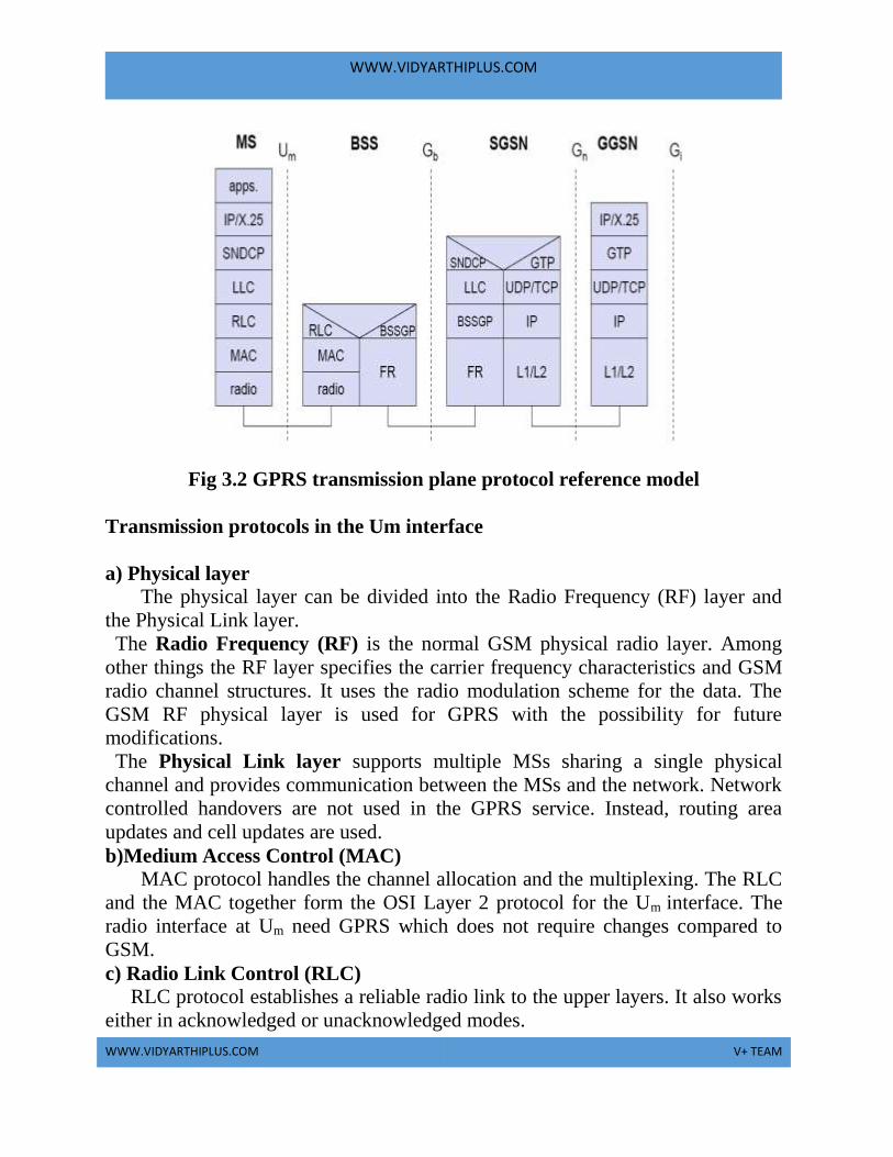
Fig 3.2 GPRS transmission plane protocol reference model
Transmission protocols in the Um interface
a) Physical layer
The physical layer can be divided into the Radio Frequency (RF) layer and
the Physical Link layer.
The Radio Frequency (RF) is the normal GSM physical radio layer. Among
other things the RF layer specifies the carrier frequency characteristics and GSM
radio channel structures. It uses the radio modulation scheme for the data. The
GSM RF physical layer is used for GPRS with the possibility for future
modifications.
The Physical Link layer supports multiple MSs sharing a single physical
channel and provides communication between the MSs and the network. Network
controlled handovers are not used in the GPRS service. Instead, routing area
updates and cell updates are used.
b)Medium Access Control (MAC)
MAC protocol handles the channel allocation and the multiplexing. The RLC
and the MAC together form the OSI Layer 2 protocol for the Um interface. The
radio interface at Um need GPRS which does not require changes compared to
GSM.
c) Radio Link Control (RLC) RLC protocol establishes a reliable radio link to the upper layers. It also works
either in acknowledged or unacknowledged modes.

WWW.VIDYARTHIPLUS.COM
WWW.VIDYARTHIPLUS.COM V+ TEAM
Logical Link Control (LLC) LLC layer establishes a secure and reliable logical link between the
MS and the SGSN for upper layer protocols. It works either in acknowledged or
unacknowledged modes. The data confidentiality is ensured by using ciphering
functions.
Subnetwork dependent convergence protocol (SNDCP) SNDCP is used to transfer data packets between SGSN and MS. It is
used to provide multiplexing of several connections of network layer onto one
logical connection of underlying LLC layer. It provides functions that help to
improve channel efficiency. This is achieved by means of compression
techniques. Data Link layer is divided into LLC layer and RLC/MAC Layer.
Transmission protocols in the Gb interface
a)Physical Layer Protocol
Several physical layer configurations and protocols are possible at the Gb
interface and the physical resources are allocated by Operation & Maintenance
(O&M) procedures. Normally a G703/704 2Mbit/s connection is provided.
b) Network Services layer
The Gb interface Network Services layer is based on Frame Relay. Frame Relay
virtual circuits are established between the SGSN and BSS. LLC PDUs from
many users are statistically multiplexed onto these virtual circuits. These virtual
circuits may traverse a network of Frame Relay switching nodes, or may just be
provided on a point to point link between the BSC and the SGSN.
Base station subsystem GPRS protocol (BSSGP)
BSSGP is used to deliver routing and QoS-related information between the BSS
and SGSN. It is to enable two physically distinct nodes, the SGSN and BSS. It is
to operate node management control functions. There is a one-to-one relationship
between the BSSGP protocol in the SGSN and in the BSS. If one SGSN handles
multiple BSSs, the SGSN has to have one BSSGP protocol device for each BSS.
BSSGP does not perform error correction and works on top of a frame relay (FR)
network.

WWW.VIDYARTHIPLUS.COM
WWW.VIDYARTHIPLUS.COM V+ TEAM
Transmission protocols in the Gn interface
a)Layer 1 and Layer 2
The L1 and the L2 protocols are vendor dependent OSI layer 1 and 2 protocols. It
carries the IP datagrams for the GPRS backbone network between the SGSN and
the GGSN.
b) Internet Protocol (IP)
The Internet Protocol (IP) datagram in the Gn interface is only used in the GPRS
backbone network. The GPRS backbone (core) network and the GPRS subscribers
use different IP addresses. This makes the GPRS backbone IP network invisible to
the subscribers and vice versa. The GPRS backbone network carries the subscriber
IP or X.25 traffic in a secure GPRS tunnel.
c) TCP or UDP
TCP or UDP are used to carry the GPRS Tunnelling Protocol (GTP) PDUs across
the GPRS backbone network. TCP is used for user X.25 data and UDP is used for
user IP data and signalling in the Gn interface.
d) GPRS tunneling protocol (GTP)
GTP is the basis for tunnel signaling. It uses two transport protocols such as
reliable TCP and non-reliable UDP. The GPRS Tunnelling Protocol (GTP) allows
multi-protocol packets to be tunnelled through the GPRS backbone between
GPRS Support Nodes (GSNs).