MP-F05, MP-F05/R, MP-F10, MP-F10/R - M&C Tech …refer to the technical data sheet or instruction...
30
Bellows pump series MP ® -F MP-F05, MP-F05/R, MP-F10, MP-F10/R Instruction Manual Version 1.04.03
Transcript of MP-F05, MP-F05/R, MP-F10, MP-F10/R - M&C Tech …refer to the technical data sheet or instruction...

Bellows pump series MP®-F
MP-F05, MP-F05/R, MP-F10, MP-F10/R Instruction Manual Version 1.04.03

2 MP-F… | 1.04.03 www.mc-techgroup.com
Dear customer, Thank you for buying our product. In this manual you will find all necessary information about this M&C product. The information in the manual is fast and easy to find, so you can start using your M&C product right after you have read the manual. If you have any question regarding the product or the application, please don’t hesitate to contact M&C or your M&C authorized distributor. You will find all the addresses in the appendix of this instruction manual. For additional information about our products, please go to M&C’s website www.mc-techgroup.com. There you can find the data sheets and manuals of our products in German and English.
Disclaimer This instruction manual does not claim to be complete and it may be subject to technical modifications. © 04/2020 M&C TechGroup Germany GmbH. The reproduction of this instruction manual as well as parts of the content are not permitted and are subject to approval by M&C TechGroup. MP® is a registered trade mark. Version: 1.04.03

www.mc-techgroup.com MP-F… | 1.04.03 3
Table of Contents
General information .................................................................................................................... 4 Declaration of conformity........................................................................................................... 4 Warranty ...................................................................................................................................... 5 Warning signs and definitions ................................................................................................... 5 Correct operation ........................................................................................................................ 7 Wrong operation ......................................................................................................................... 8 Application .................................................................................................................................. 9 7.1 MP-F05/R and MP-F10/R with integrated needle ...................................................................... 9
Technical data ........................................................................................................................... 11 8.1 Pump capacities ...................................................................................................................... 12 8.2 Dimensions ............................................................................................................................. 12
Receiving and storing the bellows pump ................................................................................ 13 Installation instructions ........................................................................................................... 14 10.1 Mounting the pump ................................................................................................................. 16 10.2 Rotating the pump head .......................................................................................................... 16 10.3 Electrical connections.............................................................................................................. 18 10.4 Pneumatic connection ............................................................................................................. 19 Start up ...................................................................................................................................... 20 Operating the pump .................................................................................................................. 21 Decommissioning ..................................................................................................................... 21 Disassembly .............................................................................................................................. 22 Maintenance .............................................................................................................................. 23 15.1 Replacing the valve plates ...................................................................................................... 25 15.2 Replacing the bellows ............................................................................................................. 26 15.3 Cleaning instructions ............................................................................................................... 27 Trouble shooting ...................................................................................................................... 28 Proper disposal of the device .................................................................................................. 29 Spare parts list .......................................................................................................................... 29 Appendix ................................................................................................................................... 30
Table of Figures Figure 1 Needle valve in a half-section view with one quarter removed .......................................... 10 Figure 2 Pump with bypass needle valve........................................................................................ 10 Figure 3 Pump capacity MP-F05 and MP-F10 ................................................................................ 12 Figure 4 Dimensions MP-F../R ....................................................................................................... 12 Figure 5 Installing the MP-F.. .......................................................................................................... 16 Figure 6 Rotating the pump head ................................................................................................... 17 Figure 7 Electrical connection MP-F.. ............................................................................................. 19 Figure 8 Pneumatic connection ...................................................................................................... 19 Figure 9 Sectional drawing MP-F.................................................................................................... 25

4 MP-F… | 1.04.03 www.mc-techgroup.com
Headquarters M&C TechGroup Germany GmbH Rehhecke 79 40885 Ratingen Germany Phone: +49 - 2102 - 935 - 0 E - mail: [email protected] Website: www.mc-techgroup.com
General information
The product described in this instruction manual has been built and tested in our production facility. All M&C products are packed to be shipped safely. To ensure the safe operation and to maintain the safe condition, all instructions and regulations stated in this instruction manual need to be followed. This instruction manual includes all information regarding proper transportation, storage, installation, opera-tion and maintenance of this product by qualified personnel. Follow all instructions and warnings closely. Read this manual carefully before commissioning and operating the device. If you have any questions regarding the product or the application, please don’t hesitate to contact M&C or your M&C authorized distributor.
Declaration of conformity
CE - Certification The product described in this operating manual complies with the following directive: Machinery Directive The requirements of the directive 2006/42/EC are met. Declaration of conformity The EU Declaration of conformity can be downloaded from the M&C homepage or directly requested from M&C.

www.mc-techgroup.com MP-F… | 1.04.03 5
Warranty
In case of a device failure, please contact immediately M&C or your M&C authorized distributor. We have a warranty period of 12 months from the delivery date. The warranty covers only appropriately used products and does not cover the consumable parts. Please find the complete warranty conditions in our terms and conditions. The warranty includes a free-of-charge repair in our production facility or the free replacement of the device. If you return a device to M&C, please be sure that it is properly packaged and shipped with protective packaging. The repaired or replaced device will be shipped free of delivery charges to the point of use.
Warning signs and definitions
Danger
The ‘Danger’ warning sign indicates that death, serious injury and/or significant material damage will be the consequence, if the appropri-ate precautions should not be taken.
Warning
The ‘Warning’ warning sign indicates that death, serious injury or damage to property may occur, if the relevant precautionary measures are not observed.
Caution
The ’Caution’ warning sign indicates that slight personal injury can occur, if the appropriate safety precautions are not ob-served.
Caution ’Caution‘ indicates that damage to property can occur, if the appropri-
ate safety precautions are not observed.
Note
‘Note’ indicates important information relating to the product or high-lights parts of the documentation for special attention.
Qualified Personnel ‘Qualified personnel’ are experts who are familiar with the installation, mounting, commissioning and operation of these types of products.
High voltages! Protect yourself and others against damages which might be caused by high voltages.
Toxic! Acute toxicity (oral, dermal, inhalation)! Toxic when in con-tact with skin, swallowed or inhaled.

6 MP-F… | 1.04.03 www.mc-techgroup.com
Corrosive! These substances destroy living tissue and equipment upon contact. Do not breathe vapors; avoid contact with skin and eyes.
Wear protective gloves! Working with chemicals, pointed objects or extremely high tempera-tures requires wearing protective gloves.
Wear safety glasses! Protect your eyes while working with chemicals or pointed objects. Wear safety glasses to avoid getting something in your eyes.
Wear protective clothes! Working with chemicals, pointed objects or extremely high tempera-tures requires wearing protective clothes.

www.mc-techgroup.com MP-F… | 1.04.03 7
Correct operation
Follow these basic safety precautions during installation, commissioning and operation of the device:
• Read this instruction manual before commissioning and operating the product. Please make sure to follow all warnings and safety instructions.
• Installation and commissioning of electrical devices must be carried out only by qualified skilled personnel in compliance with the current regulations.
• The installation and commissioning of the device must conform to the requirements of VDE 0100 ‘Regulations on the Installation of Power Circuits with Nominal Voltages below 1000 V’ and must be in compliance with all relevant regulations and standards.
• Before connecting the device, please make sure to compare the supply voltage with the specified voltage on the product label.
• Protection against contact to components carrying high voltages: Disconnect the power supply before opening the device for access. Make sure that all extern power supplies are disconnected.
• Operate the device only in the permitted temperature and pressure ranges. For details please refer to the technical data sheet or instruction manual.
• Install the device only in protected areas, sheltered from sun, rain and moisture.
• Do not use the bellows pumps MP-F05, MP-F05/R, MP-F10, MP-F10/R in hazardous areas.
• If an operation involves sample gases, which are toxic and hazardous to the health, protective measures need to be taken against any accidental leakage, e.g. unexpected damage of the pump bellows, the related tubing or tube connections.
• To troubleshoot failing or decreasing pump performance, we recommend installing a flow moni-toring device downstream from the pump.
• The pump is only designed for sample gases, which are not contaminated with particles. It might be necessary to install a suitable particle filter upstream of the pump.
• The pump is not designed for liquid. To protect the pump against condensate, a cooler might be necessary to be installed upstream of the pump.
• Only gas or gas mixtures can be used, which do not react with each other or with materials of the pump components.
• Installation, maintenance, inspections and any repairs of the devices must be carried out only by qualified skilled personnel in compliance with the current regulations.

8 MP-F… | 1.04.03 www.mc-techgroup.com
Wrong operation
Warning Please make sure to install and operate the pump for the in-tended use described in this instruction manual only.
Warning The pump can only be operated within the parameters stated in the technical data of chapter ‘8 Technical data’.
Warning
The pump is not designed for liquids or particles. It is prohibited to operate the pump with condensate. The pump head can be electrostatically charged by particles, liquids and drops of condensate. Condensate accumulated inside the pump head destroys the pump. If it is likely that humidity or condensation occurs, the pump head needs to be rotated 180° facing downwards. With the pump head facing downwards, the condensate can leave the pump head.
Warning The materials of the pump, which are in contact with the sample gas, need to be suitable for the used sample gas.
Warning In order to operate the pump, it needs to be securely installed.
Warning
Install the pump only in protected areas, sheltered from rain and moisture. Please make sure to provide sufficient ventilation.
Warning
Do not exeed the permitted maximum pressure within the pump (gauge pressure). Do not close the sample gas output. A sufficient sample gas flow needs to be provided to prevent the pump pressure from exceeding the permitted maximum pressure value. A sufficient sample gas flow also prevents the temperature of the pump head to increase over the permitted temperature range.
Warning
If components downstream from the pump can block or reduce the sample gas flow, appropriate measure, e.g. a pressure valve, needs to be installed to prevent the process pressure from exceeding the maximum permitted pressure value.

www.mc-techgroup.com MP-F… | 1.04.03 9
Application
The bellows pump MP-F… is suitable for 100 % oil-free operation of corrosive gases. The construction and performance of the pump is especially tailored to the requirements of the analysis technique. The pump is gas tight and its operation is maintenance-free. All sample contacting parts of the bellows pump MP-F are corrosion resistant. To connect the pump head to the tubing, the upper part of the pump head is also available in stainless steel (optional). The pump operates absolutely lubricant free, this prevents the sample gases from any contamination. Due to a special bellows and valve system, the pump operates maintenance-free and has a long serv-ice life. The straightforward valve design ensures low maintenance costs. The pump is available in 230 V or 115 V and in two different pump capacities:
• MP-F05 pump capacity 5 Nl/min (approx. 320 Nl/h)
• MP-F10 pump capacity 10 Nl/min (approx. 600 Nl/h) Liter capacity with a counter pressure of -/+ 50 mbar on the vacuum and pressure side.
• Option: integrated needle valve to adjust the flow rate in the pump head of the MP F.../R and/or
• Option: stainless steel pump head with NPT – thread. The sample gas line can be connected to the top or the side of the pump head. The pump head also can be rotated and mounted in 90° steps.
7.1 MP-F05/R and MP-F10/R with integrated needle
To ensure that the needle valve works properly, the output of the pump needs to be operated with at least 0.1 bar counter pressure. To adjust the pump capacity, a needle valve used as an internal pump bypass is integrated into the pump head. The optimized shape of the needle valve, makes it possible to adjust the pump capacity over a wide range. All parts of the valve, which are in contact with the sample gas, are made out of PTFE and PVDF. There are no O-rings in the needle valve. To open the needle valve completely, turn out the valve until it stays at 35 mm (lowest pump capacity). To close the needle valve completely, turn in the valve, until it stays at 25 mm (highest pump capacity) After adjusting the needle valve, the locknut (see position ①) needs to be fastening hand-tight with a wrench. This ensures that the needle valve is gas tight, and avoids accidental misalignment of the valve.
Warning
Bellows pumps series MP-F are not suitable for liquids or particles. These pumps only operate dry and particle-free gases.

10 MP-F… | 1.04.03 www.mc-techgroup.com
Figure 1 Needle valve in a half-section view with one quarter removed
Service life and reliability of the pump is increased by using a bypass needle valve. This needle valve protects the pump from unnecessary high loads or overload.
Figure 2 Pump with bypass needle valve
1

www.mc-techgroup.com MP-F… | 1.04.03 11
Technical data
Bellows Pump MP-F05 /230 V MP-F05 /115 V MP-F10 /230 V MP-F10/115 V Part No. 05P1000 05P1000a 05P1005 02P1005a Part No. with needle valve MP-F../R
05P1010 05P1010a 05P1015 05P1015a
Voltage 230 V 50 Hz 115 V 60 Hz 230 V 50 Hz 115 V 60 Hz
Voltage tolerance In accordance with IEC 60034-1 Voltage ±5 % Frequency ±2 %
Degree of protection IP 55 - DIN 40050
Capacity max. 320 Nl/h (approx. 5 l/min) Liter capacity with a counter pressure of ±50 mbar on the vacuum and pres-
sure side
600 Nl/h (approx. 10 l/min) Liter capacity with a counter pres-sure of ±50 mbar on the vacuum
and pressure side
Operating pressure Max. 0.4 to 2.2 bar abs. Max. 0.2 to 3.2 bar abs.
Gas temperature -30 to +100 °C [-22 °F to 212 °F] for dry sample gas
Ambient temperature +10 °C to +50 °C/0 °C to +50 °C for dry sample gas [+50 °F to + 122 °F/+32 °F to + 122 °F for dry sample gas]
installation altitude of < 1000 m [≈ < 3281 ft.] above sea level
Storage temperature -20 to +60 °C [-4 to +140 °F]
Sample gas connections G 1/4“ i DIN ISO 228/1
Gas tightness of pump head < 6 x 10⁻³ mbar l/s
Power consumption 65 W
Cos φ 0.94 0.98 0.94 0.98
Current consumption 0.30 A 0.57 A 0.30 A 0.57 A
Cable fittings M20 x 1.5 clamp range 5.5 – 10 mm
Electrical equipment stand-ard EN 60204-1
Material of sample gas con-tacting parts PTFE, PFA, FEP (+PVDF for type /R)
Weight 4.7 kg [≈ 10.4 lbs]
4.35 kg [≈ 9.6 lbs]
4.7 kg [≈ 10.4 lbs]
4.35 kg [≈ 9.6 lbs]
Options 05P1050 Mounting bracket with 4 anti-vibration pads for bellows pump MP-F
05P1060 Extra charge for upper pump head of bellows pump MP-F out of stain-less steel
05P1070 Extra charge for upper pump head of bellows pump MP-F../R out of stainless steel with needle valve out of PVDF
Material abbreviations according to ISO 1629 and 1043.1

12 MP-F… | 1.04.03 www.mc-techgroup.com
8.1 Pump capacities
Figure 3 Pump capacity MP-F05 and MP-F10
8.2 Dimensions
Figure 4 Dimensions MP-F../R

www.mc-techgroup.com MP-F… | 1.04.03 13
Receiving and storing the bellows pump
• Please remove the bellows pump carefully from the packaging. Check the scope of the delivery specified on the delivery note. Please make sure that you have received all items stated on the delivery note.
• Please check the unit for any transport damages after receipt and report any complaints to the transport company immediately.
Note
The bellows pump should be stored in a protected, frost-free room!

14 MP-F… | 1.04.03 www.mc-techgroup.com
Installation instructions
All relevant regulations regarding accident prevention and safety need to be met during installation and operation of the pump.
Warning
High voltage! Working without disconnecting the power supply may cause an electrical shock. Disconnect power supply before any assembly, maintenance or repair work. Secure the pump against accidental restart!
Warning
Protect yourself and others against contact to parts of the pump, e.g. elec-trical connections, which may be still connected to a power supply. Protect yourself and others against contact to moving parts of the pump. Protect the pump against entering of water and particles.
Note
Make sure to comply with the current safety regulations regarding the sample gas used in the pump. Install the pump in well ventilated rooms and away from heat sources to prevent any heat accumulation. For outdoor installation, install the pump in a protective housing. The housing needs to provide protection against frost in winter, and ventilation in summer. Avoid exposure to direct sunlight.
Warning
Pumps contain mechanically moving parts that can cause vibrations. In order to avoid damage to the pump and peripheral components / facilities and to minimize acoustic noise, appropriate vibration isolation must be provided. M&C offers e.g. vibration control air springs to de-couple the vibration source from the vibration-free environment. Especially the connections of the sample gas lines to the pump head need to be de-coupled.
Warning
The components, which will be connected to the pump, need to meet the requirements of the pneumatic data of the pump. For details please refer to the technical data sheet or manual. Make sure to comply with the current safety regulations when connecting the pump to the power supply. Make sure to comply with the current safety regulations regarding the sample gas used in the pump.
www.mc-techgroup.com MP-F… | 1.04.03 15
Aggressive condensate possible. Chemical burns possible due to aggressive media! For general electrical and mechanical work on the pump, wear personal protective equipment (PPE) in accordance with the risk assessment.
Warning
Condensate accumulated inside the pump head destroys the pump. If it is likely that humidity or condensation occurs, the pump head needs to be rotated 180° facing downwards. With the pump head facing down-wards, the condensate can leave the pump head.
Note
To immediately detect pump malfunctions, we recommend installing a flow monitoring device downstream from the pump.
16 MP-F… | 1.04.03 www.mc-techgroup.com
10.1 Mounting the pump
The mounting site needs to comply with the following requirements:
• Ambient temperature range during operation: +10 to +50 °C/0 to +50 °C for dry sample gas [+50 to + 122 °F/+32 to + 122 °F for dry sample gas].
• The pump is rated IP55 (protection class) and it needs to be protected against water and dust ingress.
• During operation, the pump needs to have an adequate supply of cooling air for heat dissipation.
• If possible, install the pump at the highest elevation point of your system, to make sure that no condensate and no dust will ingress the pump.
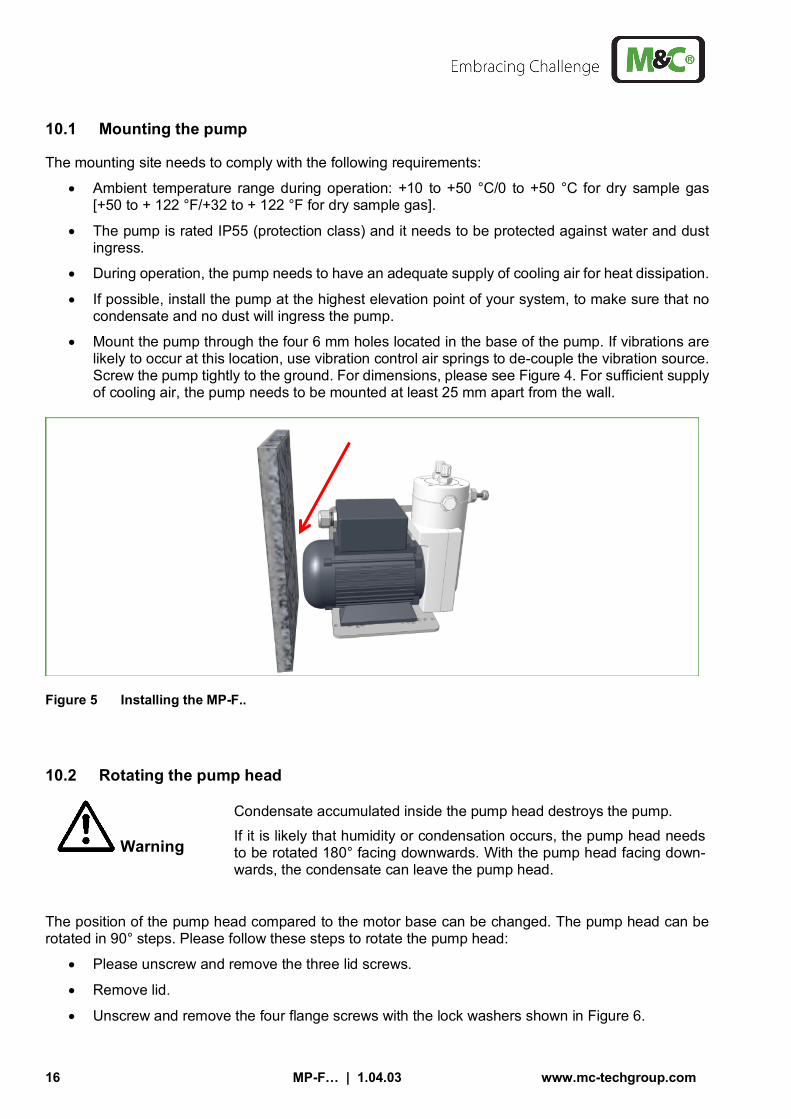
• Mount the pump through the four 6 mm holes located in the base of the pump. If vibrations are likely to occur at this location, use vibration control air springs to de-couple the vibration source. Screw the pump tightly to the ground. For dimensions, please see Figure 4. For sufficient supply of cooling air, the pump needs to be mounted at least 25 mm apart from the wall.
Figure 5 Installing the MP-F..
10.2 Rotating the pump head
Warning
Condensate accumulated inside the pump head destroys the pump. If it is likely that humidity or condensation occurs, the pump head needs to be rotated 180° facing downwards. With the pump head facing down-wards, the condensate can leave the pump head.
The position of the pump head compared to the motor base can be changed. The pump head can be rotated in 90° steps. Please follow these steps to rotate the pump head:
• Please unscrew and remove the three lid screws.
• Remove lid.
• Unscrew and remove the four flange screws with the lock washers shown in Figure 6.

www.mc-techgroup.com MP-F… | 1.04.03 17
• Now you can change the position of the pump head in 90° steps.
• After rotating the pump head to the selected position, please insert the four flange screws with the lock washers back again and tighten them.
• Put the lid back on and secure the lid by tightening the three lid screws.
Figure 6 Rotating the pump head

18 MP-F… | 1.04.03 www.mc-techgroup.com
10.3 Electrical connections
Be sure to observe all relevant safety regulations during the electrical installation of the pump. The main power supply must be turned off before connecting the pump.
Danger
Do not operate bellows pumps MP F.. in explosive environments!
Warning
Incorrect voltage can destroy the device. When connecting the equipment, please ensure that the supply voltage is identical with the information provided on the model type plate. The supply voltage is only allowed to deviate max. ±5 % and frequency ±2 % from the indication on the model type plate. Exceeding the tolerance increases the heating and influences the electro-magnetic compatibility (EMC). The air-cooled motor is designed for an ambient range +10 to +50 °C/0 to +50 °C for dry sample gas [+50 to +122 °F/+32 to +122 °F for dry sample gas] and an installation altitude of < 1000 m [≈ < 3281 ft.] above sea level.
Note
The installation and commissioning of the device must conform to the re-quirements of VDE 0100 ‘Regulations on the Installation of Power Circuits with Nominal Voltages below 1000 V’ and must be in compliance with all relevant regulations and standards! The current supply circuit of pump type MP-F... (230 V) has to be provided with a motor circuit braker 0.3 A corresponding to the rated current (over-current protection). The current supply circuit of pump type MP-F... (115 V) has to be provided with a motor circuit braker 0.57 A corresponding to the rated current (over-current protection).
• Install a device to disconnect the pump motor from all poles of the main power supply according
to EN 60335-1.
• The pump needs to be installed in such a way, that contact to parts carrying live voltage (e.g. electrical connections) is impossible.
For wiring the cables and wires, please follow these steps:
• Unscrew and remove the lid of the connection box.
• Lead connection cable (Ø ≥ 0.75 mm2 Cu) through cable gland (clamping range 5.5 - 10 mm) and connect according to Figure 7 or the drawing printed inside of the connection box lid.
• Keep the inside of the junction box clean.
• Close lid of the junction box. Please make sure that the lid does close correctly, and the sealing of the box is still in good condition.

www.mc-techgroup.com MP-F… | 1.04.03 19
Figure 7 Electrical connection MP-F..
10.4 Pneumatic connection
• Remove protective plugs from the gas connection threads (thread size G1/4“).
• It is possible to screw the tube connection fittings into the pump head either from the top or side. To screw-in the tube connection fittings from the side, please remove protective plugs from the gas connection threads on the side and screw them into the threads on the top.
• Accessory parts like tube connection fittings are screwed into the connection threads with sealing tape (when using straight M&C connectors, no sealing tape is necessary). Connection fittings for DN 4/6 or DN 6/8 are optional and available at M&C.
The tube connection for M&C fittings is described below.
Figure 8 Pneumatic connection
PE
N L

20 MP-F… | 1.04.03 www.mc-techgroup.com
• To connect the suction and pressure line, please loosen the union nut of the compression ring fitting counterclockwise. Be sure to remove the union nut carefully from the fitting. There is a loose clamp ring inside the union nut.
• Slide the nut over the connecting tube.
• Slide the clamp ring with the thicker bulge facing the nut, over the connecting tube.
• Slide the connecting tube on the support nipple of the fitting.
• Hand-tighten the nut. The connecting tube is now slip-proof and pressure-tight mounted to the tube connection fitting.
• Suction and pressure lines need to be installed in such a way that the pump is protected against ingress of condensate or dust.
Note
Because of compression of sample gases, it is possible that condensate builds up in the pressure line. This pressure must be reduced. For example, reduce the pressure with a valve in the pressure line upstream of the pump or with the integrated needle valve.
Start up
Before commissioning, be sure to comply with all applicable facility- and process-specific safety measures. Make sure to operate the pump for the intended use described in chapter 5 only. Before commissioning, be sure to comply with all applicable safety regulations and measures of the involved sample gases. The materials of the pump, which are in contact with the sample gas, need to be suitable for the used sample gas. Before operating the pump, make sure that the materials of the pump head, bellows and valves (for pump materials: see chapter ‘8 Technical data’) are suitable for the used sample gas. Follow these instructions before initial start-up:
• Ensure that the pump is securely tightened to the surface.
• Only sample gas which withstands the pressure and temperature within the pump and does not built-up condensate is suitable for operation.
• Make sure that the pump does not start-up against pressure or vacuum.
• Before start-up and restarting, atmospheric pressure must be present in the suction and pressure lines. Even when the power has been cut off for only a short period, the suction and pressure lines need to have atmospheric pressure. After a pump standstill, the pressure in the sample gas lines needs to be set back to atmospheric pressure.
• Never exceed the maximum permitted operating pressure (for details see chapter ‘8 Technical data’).
• Only insert a sample gas flow controller or restriction device into the suction line. This protects the pump bellows from damages and prevents the pressure from exceeding the maximum per-mitted operating value.
• Monitor the pressure, when a sample gas flow controller or restriction device is inserted in the suction line. This prevents the pressure to exceed the maximum permitted operating pressure.
• Monitor the pressure if necessary.

www.mc-techgroup.com MP-F… | 1.04.03 21
• If there is a chance that components installed downstream of the pump may block or reduce the sample gas flow, it is necessary to install e.g. a pressure relief valve. This prevents the pressure to exceed the maximum permitted operating value.
• The bellows and valve plates are the only consumable parts of the pump. Wear is usually indi-cated by a drastic reduction in the pneumatic performance. The valve plates need to be replaced, when they are < 1.6 mm [≈ 0.063”] thick. When replacing parts, please have a look at chapter ’15 maintenance’.
Operating the pump
The following ambient conditions are necessary for operating the pump:
• Ambient temperature range during operation: +10 to +50 °C/0 to +50 °C for dry sample gas [+50 to + 122 °F/+32 to + 122 °F for dry sample gas].
• Operate the pump only in well ventilated rooms, and away from heat sources to prevent any heat accumulation.
• Please check immediately for damages, when the motor makes unusual running noises. Dam-aged ball bearings could be the cause of these running noises.
Decommissioning
Before switching off the pump (decommissioning), the pump needs to be purged with inert gas or air.
Note
The room or area where the pump is installed in must be kept frost-free at all times! The ambient temperature range is +10 to +50 °C/0 to +50 °C for dry sample gas [+50 to +122 °F/+32 to +122 °F for dry sample gas] even after decommissioning the pump.
Aggressive condensate possible. Chemical burns possible due to aggressive media! For general electrical and mechanical work on the pump, wear personal protective equipment (PPE) in accordance with the risk assessment.

22 MP-F… | 1.04.03 www.mc-techgroup.com
Disassembly
Note Before switching off the pump (decommissioning), the pump needs to be purged with inert gas or air, and it needs to be dried.
Aggressive condensate possible. Chemical burns possible due to aggressive media! For general electrical and mechanical work on the pump, wear personal protective equipment (PPE) in accordance with the risk assessment.
Before disassembling the pump, follow these warnings and safety instructions:
Warning
High voltage! Working without disconnecting the power supply may cause an elec-trical shock. Disconnect power supply before any assembly, mainte-nance or disassembly. Secure the pump against accidental restart.
Danger
There may be harmful sample gases in the pump. Prevent potentially harmful gases from escaping the open sample gas lines during disas-sembly.
You can disassemble the pump now.

www.mc-techgroup.com MP-F… | 1.04.03 23
Maintenance
It is necessary to schedule maintenance work at least twice a year. The intervals between servicing are dependent on the process and system conditions in your facility. The facility QA/QC plan should address the frequency for maintenance and should be updated based on your operations.
Danger
Follow all safety notes and descriptions stated in this manual. There may be harmful sample gases in the pump. Prevent potentially harmful gases from escaping the open sample gas lines during mainte-nance. Purge the pump with inert gas or air before servicing.
Warning
High voltage! Working without disconnecting the power supply may cause an electrical shock. Disconnect power supply before any assembly, maintenance or disassembly. Secure the pump against accidental restart.
Aggressive condensate possible. Chemical burns possible due to aggressive media! For general electrical and mechanical work on the pump, wear personal protective equipment (PPE) in accordance with the risk assessment.
The four hexagon socket screws, see Figure 9 part G, need to be re-tightened to a value of 5 Nm by using a torque wrench. Start to re-tighten one screw. Tighten the opposite screw to the same amount, then select the adjacent pair. Repeat in the same sequence to reach the value of 5 Nm. The bellows and valve plates are the only consumable parts of the pump. The valve plates need to be replaced, when they are < 1.6 mm [≈ 0.063”] thick. They are easy to replace. Please refer to the spare parts list in chapter 17 for our recommended spare parts.

24 MP-F… | 1.04.03 www.mc-techgroup.com
Inspect the following pump components
Action
Pump Check pump for external damages and any leakage in regular inter-vals, at least two times per year.
Capacitor Check the conditions of the adhesive covers of the vents in regular intervals. Replace capacitor with damaged adhesive cover.
Bellows and valve plates Replace at least when performance of the pump decreases. The valve plates need to be replaced when they are < 1.6 mm [≈ 0.063”] thick.
Connecting rod bearings Need to be replaced after 20 000 operating hours or 24 months of operation, whichever occurs first.
Motor bearings Need to be replaced after 20 000 operating hours or 24 months of operation, whichever occurs first.
Fittings, connections, inlets Check in suitable intervals. Replace when damaged with original parts in perfect condition.
Equipotential bonding Check equipotential bonding between pump enclosure and motor. The equipotential bonding needs to be lower than 0.3 Ohm. Use lock washers for the screws.
Additional components, ac-cessories
During maintenance, any upstream filters, separators, or coolers must be checked for proper functioning.
Note
If there are any damages to the connection rod, e.g. a loose threaded pin M8 or loose ball bearings, the complete unit with connection rod and bearings need to be replaced (see chapter 17 for more details) The eccentric is glued to the motor shaft by using Loctite 270. This connection is additionally secured by a set screw.

www.mc-techgroup.com MP-F… | 1.04.03 25
15.1 Replacing the valve plates
Note
If you replace the valve plates, we also recommend to replace the O-rings C at the same time.
For replacing the valve plates, the sample gas fittings don’t need to be dismounted. To replace the valve plates, proceed as follows: 1. Unscrew the crankcase cover. To do this, loosen the 3
hexagon socket screws F (3 mm spanner). 2. Loosen the four hex socket screws G (3 mm spanner). 3. Remove pressure ring H. 4. Remove upper pump head A.
O-rings C and valve plates B are freely accessible now. 5. The valve plates and O-rings can now be cleaned or re-
placed. 6. Clean valve seats and pump head with an adequate sol-
vent (e.g. alcohol) and use oil-free compressed air to re-move dust particles from the parts.
Figure 9 Sectional drawing MP-F..
After replacing or cleaning the valve plates and O-rings, follow these steps to re-assemble the pump: 1. Insert O-rings C into the grooves, and place valve plates B back into the cleaned valve seats. Make
sure that the valve plates are in the correct position.
Caution Turn pump head A only to the right and up-wards. This prevents the bellows from loosen-ing from the connecting rod.
Note
On the pressure side, the smooth side of Valve B is facing downwards, and on the suction side the smooth side of Valve B is facing upwards (operating direction is marked with an arrow on the pump head).
G H
D
E
A
C
B
F

26 MP-F… | 1.04.03 www.mc-techgroup.com
2. Install the upper pump head A and then the pressure ring H again. Align both so that the screws fit into the threads in the housing.
3. Check that the bellows are seated correctly. The bellows must be attached to the connecting rod. 4. Fasten the pressure ring H with the four hexagon socket screws G. First tighten the screws by hand.
Start lightly to tighten one screw. Tighten the opposite screw to the same amount, then select the adjacent pair. Repeat in the same sequence, going for a hand-tight setting.
5. Then tighten the four hexagon socket screws alternately in the same sequence with a torque to a value of 5 Nm.
6. Screw the crankcase cover back on again. Tighten the three hexagon socket screws F (wrench 3 mm) by hand.
15.2 Replacing the bellows
Note
If you replace the bellows, we also recommend replacing the O-rings C at the same time.
To replace the bellows, proceed as follows: 1. Unscrew the crankcase cover. To do this, loosen the 3 hexagon socket screws F (3 mm spanner). 2. Loosen the four hex socket screws G (3 mm spanner). 3. Remove pressure ring H. 4. Remove upper pump head A.
5. Remove lower pump head D. For easier removal of the lower pump head D, please close one of
the boreholes in the valve seat with your fingers and blow pressured air into the other borehole. This will loosen the lower pump head D.
6. Unscrew the bellows E from the connection rod. Please make sure to leave any spacers which might be there, on the threaded pin.
7. Screw new bellows hand-tight onto the connection rod.
After replacing the bellows, please follow these steps to re-assemble the pump: 1. Put lower pump head D back into place. 2. Insert O-rings C into the grooves, and place valve plates B back into the cleaned valve seats. Make
sure that the valve plates are in the correct position.
Caution Turn pump head A only to the right and upwards. This prevents the bel-lows from loosening from the connecting rod.
Note
On the pressure side, the smooth side of Valve B is facing downwards, and on the suction side, the smooth side of Valve B is facing upwards (operating direction is marked with an arrow on the pump head).

www.mc-techgroup.com MP-F… | 1.04.03 27
3. Install the upper pump head A and then the pressure ring H again. Align both so that the screws fit into the threads in the housing.
4. Check that the bellows are seated correctly. The bellows must be attached to the connecting rod. 5. Fasten the pressure ring H with the four hexagon socket screws G. First tighten the screws by hand.
Start lightly to tighten one screw. Tighten the opposite screw to the same amount, then select the adjacent pair. Repeat in the same sequence, going for a hand-tight setting.
6. Then tighten the four hexagon socket screws alternately in the same sequence with a torque to a value of 5 Nm.
7. Screw the crankcase cover back on again. Tighten the three hexagon socket screws F (wrench 3 mm) by hand.
15.3 Cleaning instructions
• When changing valve plates and bellows, inspect all parts for contamination before assembling the pump head and clean them if necessary.
• Only use adequate solvents (e.g. alcohol) to prevent corrosion of the plastic parts (PTFE, PFA,
FEP). If available, use oil-free compressed air to remove dust particles from the parts.

28 MP-F… | 1.04.03 www.mc-techgroup.com
Trouble shooting
Warning
High voltage! Working without disconnecting the power supply may cause an electrical shock. Disconnect power supply before any assembly, maintenance or disassembly. Secure the pump against accidental restart.
Problem/Indication Possible cause Check/Action
Pump produces no flow
No main supply Check power supply; Check power cable for correct fit.
Connections or lines are blocked.
Remove blockage.
An external valve is closed or a filter is blocked.
Open valve or clean contaminated/blocked fil-ter
Liquid (condensate) has col-lected in the pump head.
Operate pump with air for a few minutes. In-stall the pump at the highest elevation point of your system.
Flow, pressure or vakuum too low
Bellows or valves are damaged or worn out.
Change bellows or/and valves. The valve plates need to be replaced, when they are < 1.6 mm [≈ 0.063”] thick.
The pump is not designed for these operating parameters.
Compare the actual operating parameters: pressure, vacuum and capacity with the data in chapter ‘8 Technical data’.
There is overpressure on the pressure side and at the same time vacuum on the suction side.
Check the pump with pressure less suction side and compare values with parameter characteristic graph. If ok: check system pa-rameters; not ok: see "Bellows or valves are damaged or worn out".
Pneumatic lines or connecting parts have a too small cross-section.
To measure the performance values, uncou-ple the pump from the system; even a line with a too small cross-section or e. g. a valve installed in the system can change the meas-ured value considerably.
A leak at the connectors, lines or pump head. Bellows or valve plate is damaged, or pump head is contaminated.
Seal the leak, tighten the screws, replace damaged parts, clean or replace contami-nated parts.

www.mc-techgroup.com MP-F… | 1.04.03 29
Proper disposal of the device
At the end of the life cycle of our products, it is important to take care of the appropriate disposal of obsolete electrical and non-electrical devices. To help protect our environment, please follow the rules and regulations of your country regarding recycling and waste management.
Spare parts list
The replacement interval for spare parts and consumables depends on the specific operating condition of the bellows pump. The quantities recommended in the following table are based on experience. Your replacement intervals will be based on your operating conditions.
Bellows pump MP-F05, MP-F10, MP-F05/R, MP-F10/R (C) Consumable parts (R) Recommended spare parts (S) Spare parts Recommended quantity
being in operation [years] Part No. Description C/R/S 1 2 3 95P0010 Bellows MP-F PTFE C - - 1
90P1110 Valve plate MP-F C 2 4 6
95P0035 O-ring FEP 18x2 MP-F R 2 4 6 95P0030 Lower pump head MP-F, material: PTFE S - - -
95P0025 Upper pump head MP-F, material: PTFE S - - -
95P0037 Spare parts kit for bellows pump with 2 x valve plates MP-F, 2 x O-rings FEP 18 x 2 MP-F and 1 x bellows MP-F.
S - - -
95P0039 Spare screws set for mounting the pump head with 4 x spring washers M4 and 4 x allen socket head screws M4 x 55
S - - -
95P0040 Connection rod with eccentric and ball bearring for MP-F05
S - - -
95P0045 Connection rod with eccentric and ball bearring for MP-F10
S - - -
95P0026 Pump head MP-F above with borehole for nee-dle valve, material: PTFE
S - - -
90P6030 Needle valve for MP-F../R, Sealing ring and nee-dle, material: PTFE
S - - -
90P6015 Spare needle for MP-F../R, material: PTFE S - - -
90P6020 Sealing ring for needle valve in MP-F../R, mate-rial: PTFE
S - - -

30 MP-F… | 1.04.03 www.mc-techgroup.com
Bellows pump MP-F05, MP-F10, MP-F05/R, MP-F10/R (C) Consumable parts (R) Recommended spare parts (S) Spare parts Recommended quantity
being in operation [years] Part No. Description C/R/S 1 2 3 90P6025 Adapter for needle valve in MP-F/R, material:
PTFE S - - -
PVDF male connectors with G-thread (ISO 1010031) C) Consumable parts (R) Recommended spare parts (S) Spare parts Recommended amount
based on number of years of operation [years]
Part No. Description C/R/S 1 2 3 05V1060 Straight male connector DN 4/6-G1/4”
material: PVDF S - - -
05V1065 Straight male connector DN 6/8-G1/4” material: PVDF
S - - -
05V6600 Verrule DN 4/6, PVDF S 1 2 3
05V6602 Verrule DN 6/8, PVDF S 1 2 3 05V6605 Union nut DN 4/6, PVDF S 1 2 3
05V6607 Union nut DN 6/8, PVDF S 1 2 3
Appendix
Further product documentation can be seen and downloaded from our home page: www.mc-techgroup.com