Movitec A - COMET Home Page centrifugal pumps, with suction and discharge nozzles of identical...
36
Movitec V Movitec LHS Type Series Booklet 1798.56/4-10 Movitec A High-pressure In-line Pumps 60 Hz Fields of Application Movitec V(S) and LHS are employed for general water supply, sprinkling, irrigation and pressure boosting duties, for warm water, hot water and cooling water recirculation, and conden- sate transport. They are installed in boiler feed circuits, domes- tic water supply systems, washing plants, water treatment and filter systems. They are used for degreaser baths/alkaline cleaning baths, alkalines and oils/emulsions, as well as for fire- fighting, reverse osmosis and surface treatment applications. Design Multi-stage, vertical (horizontal installation see page 5) high- pressure centrifugal pumps, with suction and discharge nozzles of identical nominal diameters arranged opposite to each other (in-line design). Materials Standard variants: V: All hydraulic components are made of stainless steel AISI 304 VS, LHS: All hydraulic components are made of stainless steel AISI 316 Shaft Seal Single-acting, uncooled mechanical seal in accordance with EN 12756. Drive Electric motor, 60 Hz, air-cooled, 2- and 4-pole, standard KSB motor with main dimensions to IEC. Other motor makes subject to prior consultation with KSB. Movitec V, VS, LHS with PTC resistors for 3 kW and above. Variants: single-phase a.c. motor, frequency-controlled drives. Designation Movitec V S F 10-- 3 Type series Movitec V Material variant Flange design Size Number of stages Movitec LHS 6 -- 10 Type series Size Number of stages Material variant: blank or S, see page 3 Flange design/connection: F= Round flange V= Victaulic coupling Operating Data Movitec V(S) Capacities Q up to 90 m 3 /h, (25 l/s) Heads H up to 258 m Operating pressures p d up to 25 bar 1 ) Operating temperatures t --15 _C to +120 _C Movitec LHS Capacities Q up to 8.6 m 3 /h, (2.4 l/s) Heads H up to 415 m Operating pressures p d up to 40 bar 1 ) Operating temperatures t --15 _C to +120 _C 1 ) The sum of inlet pressure and head at zero flow point must not ex- ceed the value stated. Conformity Marks CE ACS (Movitec V) ATEX group II, cat. 2 and 3 on request
Transcript of Movitec A - COMET Home Page centrifugal pumps, with suction and discharge nozzles of identical...

Movitec V Movitec LHS
Type Series Booklet1798.56/4-10 Movitec A
High-pressure In-line Pumps60 Hz
Fields of ApplicationMovitec V(S) and LHS are employed for general water supply,sprinkling, irrigation and pressure boosting duties, for warmwater, hot water and cooling water recirculation, and conden-sate transport. They are installed in boiler feed circuits, domes-tic water supply systems, washing plants, water treatment andfilter systems. They are used for degreaser baths/alkalinecleaning baths, alkalines and oils/emulsions, as well as for fire-fighting, reverse osmosis and surface treatment applications.
DesignMulti-stage, vertical (horizontal installation see page 5) high-pressure centrifugal pumps, with suction and dischargenozzles of identical nominal diameters arranged opposite toeach other (in-line design).
MaterialsStandard variants:V: All hydraulic components are made of stainless
steel AISI 304VS, LHS: All hydraulic components are made of stainless
steel AISI 316
Shaft SealSingle-acting, uncooled mechanical seal in accordance withEN 12756.
DriveElectric motor, 60 Hz, air-cooled, 2- and 4-pole, standard KSBmotor withmain dimensions to IEC.Othermotormakes subjectto prior consultation with KSB.Movitec V, VS, LHS with PTC resistors for 3 kW and above.Variants: single-phase a.c. motor, frequency-controlled drives.
DesignationMovitec V S F 10 -- 3
Type seriesMovitec VMaterial variantFlange designSizeNumber of stages
Movitec LHS 6 -- 10Type seriesSizeNumber of stages
Material variant: blank or S, see page 3Flange design/connection: F = Round flange
V = Victaulic coupling
Operating DataMovitec V(S)Capacities Q up to 90 m3/h, (25 l/s)Heads H up to 258 mOperating pressures pd up to 25 bar 1)Operating temperatures t --15 _C to +120 _C
Movitec LHSCapacities Q up to 8.6 m3/h, (2.4 l/s)Heads H up to 415 mOperating pressures pd up to 40 bar 1)Operating temperatures t --15 _C to +120 _C1) The sum of inlet pressure and head at zero flow point must not ex-
ceed the value stated.
Conformity MarksCEACS (Movitec V)ATEX group II, cat. 2 and 3 on request

Movitec A
2
Selection chartsn≈ 3500 1/min
For Movitec 2, 4, 6, 10 15 and 90 please refer to type series booklet Movitec B, reference No. 1798.561-10
n≈ 1750 1/min
V(S) 2
LHS 6
VC 90V(S) 90
V(S) 4 V(S) 32 V(S)45
V(S)65
V(S)6
V(S)10
V(S) 15
VC 90V(S) 90
V(S) 24V(S) 10 V(S) 15

Movitec A
3
MaterialsPart No. Description Material
Movitec V Movitec VS Movitec LHS
101 Pump casing 1.4301 1.4401 1.4408
108 Stage casing 1.4301 1.4404
160 Cover 1.4301 1.4404
171 Diffuser 1.4301 1.4404 --
10-6 Pump shroud 1.4301 1.4404
210 Shaft 1.4305 1.4401
230 Impeller 1.4301 1.4404
341 Motor stool JL 1040 1.4408
412 O-ring EPDM VITON
525 Spacer sleeve 1.4301 1.4404
529 Bearing sleeve Tungsten-carbide1) Bearing Ceramic
890 Baseplate JL 1040 --
905 Tie bolt 1.4057
920 Nut 1.4301 1.4404
932 Circlip 1.4571
1) Rigidly connected to stage casing 108 or diffuser 171
Legend of materialsDescription Code and material no. Standard to ASTM
Cast iron JL1040 / GJL-250 EN 1561 A48:40B
Nickel chrome steel 1.4301 / X5CrNi18-10 EN 10088 A276:304
Nickel chrome molybdenum steel 1.4404 / X2CrNiMo 17-12-2 EN 10088 A276:316L
Carbon nickel chromium molybdenum steel 1.4408 / GX5CrNiMo19-11-2 EN 10213 A743CF8M
Nickel chrome molybdenum steel 1.4571 / X6CrNiMoTi17-12-2 EN 10088 A276:316
Nickel chrome steel 1.4057+QT800 /X17CrNi16-2--QT800
EN 10088-3 A276:431
1.4305 / X8CrNiS 18-9 EN 10088 A276:303
1.4401 / X5CrNiMo 17-12-2 EN 10088 A276:316
1.4308 / GX5CrNi 19-10 EN 10283 A743:CF8
Please note: The indication of the material designations to ASTM / AISI is not binding.
BearingsAll V, VS and LHS pumps are supplied with tungsten carbideplain bearing at the hydraulic rotor.

Movitec A
4
Material CodesMechanical seal Description Code letter to
EN 12756Material
Spring-loaded ring Q1U3
Silicon carbide (sintered pressure less)Tungsten carbide (CrNiMo-binder)
Seat ring BU3
Resin-impregnated carbon graphiteTungsten carbide (CrNiMo-binder)
Elastomer EVX4
EPDM (Ethylene Propylene rubber)Fluorcarbon rubber (Viton)HNBR
Spring G CrNiMo steel
Other metal parts G CrNiMo steel
Code number 1314151617
Q1BEGGQ1BVGGU3U3X4GGU3U3VGGU3BVGG
Silicon carbide/Carbon/EPDMSilicon carbide/Carbon/VitonTungsten carbide/Tungsten carbide/HNBRTungsten carbide/Tungsten carbide/VitonTungsten carbide/Carbon/Viton(40 bar seal; only for Movitec LHS)
Pressure and Temperature LimitsTemperature of
di d 3)Flange variant /C i
Material variant Max. operating1)
Code number Mechanical seal 5)pmedium pumped t 3)
g /Connection
p gpressure ps 1) standard optional
– 15 _C to + 120 _C VF = round flange 2) Movitec VF
Movitec VSF
16 up to 25 bar
16 up to 25 bar
13
14
14, 15, 16
13, 15, 16
– 15 _C to + 120 _C VSV = Victaulic coupling Movitec VV
Movitec VSV
up to 25 bar
up to 25 bar
13
14
14, 15, 16
13, 15, 16
– 15 _C to + 120 _C LHS = round flange 4) Movitec LHS up to 40 bar 17 --
1) The sum of inlet pressure and head at zero flow point must not exceed the value stated.2) Drilled to EN 1092-2 PN 25 (optional ASME B 16.1 Class 250 or JIS B2238 16K)3) Subject to application limits (see List of Media Handled)4) Drilled to EN 1092-2 PN 405) Movitec 24, 32 and 45 from 11 kW with cartridge seal; Movitec 65 generally with cartridge seal
Movitec A
5
Horizontal installation
The Movitec can be installed horizontally in systems where theinstallation conditions do not allow vertical installation.
Motor flange B14 (0.37 to 4.0 kW)
Motor flange B5 (5.5 and 7.5 kW)
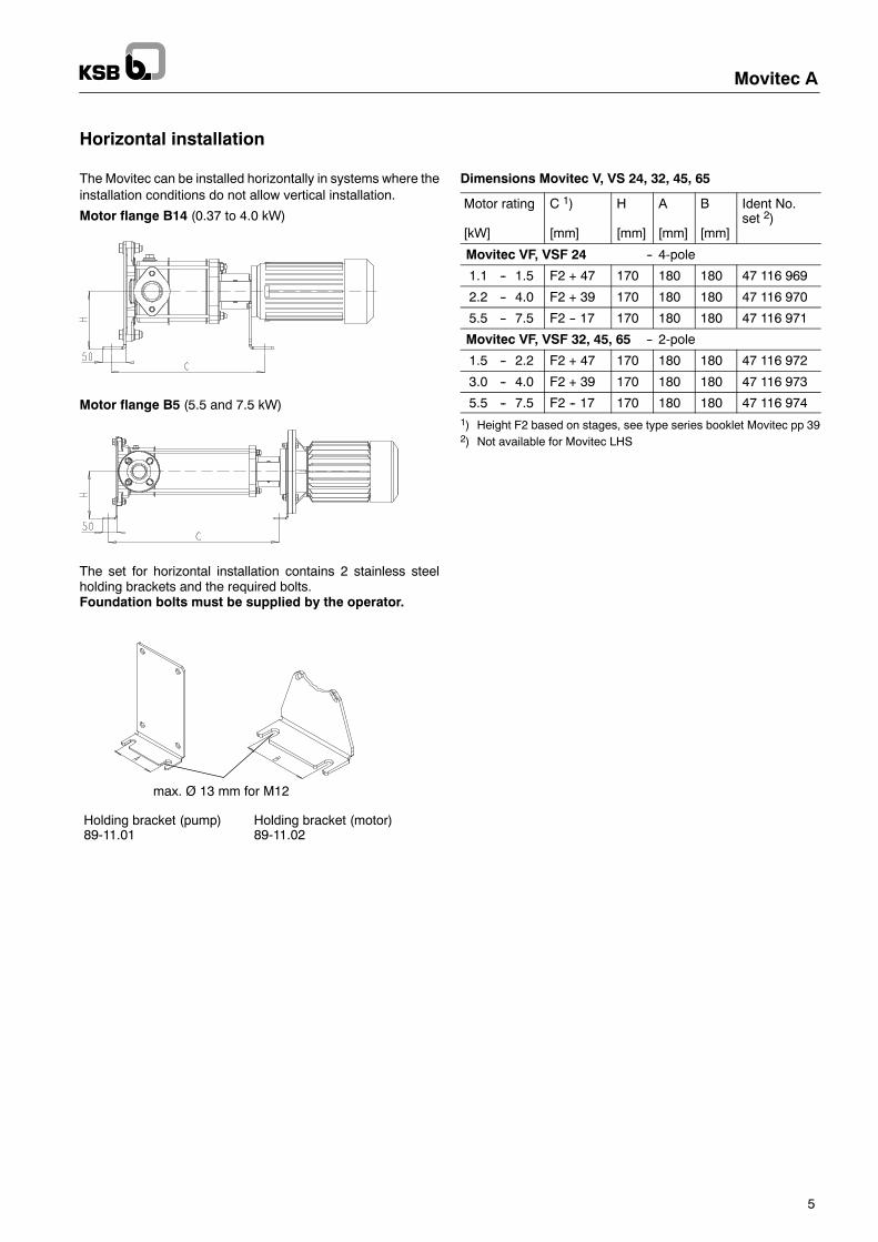
The set for horizontal installation contains 2 stainless steelholding brackets and the required bolts.Foundation bolts must be supplied by the operator.
max. Ø 13 mm for M12
Holding bracket (pump)89-11.01
Holding bracket (motor)89-11.02
Dimensions Movitec V, VS 24, 32, 45, 65
Motor rating
[kW]
C 1)
[mm]
H
[mm]
A
[mm]
B
[mm]
Ident No.set 2)
Movitec VF, VSF 24 -- 4-pole
1.1 -- 1.5 F2 + 47 170 180 180 47 116 969
2.2 -- 4.0 F2 + 39 170 180 180 47 116 970
5.5 -- 7.5 F2 -- 17 170 180 180 47 116 971
Movitec VF, VSF 32, 45, 65 -- 2-pole
1.5 -- 2.2 F2 + 47 170 180 180 47 116 972
3.0 -- 4.0 F2 + 39 170 180 180 47 116 973
5.5 -- 7.5 F2 -- 17 170 180 180 47 116 9741) Height F2 based on stages, see type series booklet Movitec pp 392) Not available for Movitec LHS

Movitec A
6
Design Features Movitec V(S)
Universal high-pressure pumpup to 25 bar• --15 _C to 120 _C• Also suitable for chemicallyaggressive fluids
Service-friendly, robustthree-phase motor• Multi-rangevoltage/frequency
• Enclosure IP 55• Thermal class F• With PTC thermistor> 3 kW
Easy-to-fit shaft made ofhigh-alloy steel, firmconnection between shaftand impeller
Low-noise:Flow noise is damped bypump shroud
Corrosion-resistant:• Hydraulic components andpump shroud made ofhigh-alloy stainless steel
• Movitec V with pump shroudmade of CrNi sheet steel
Reliable and service-friendlyshaft seal• Standardised mechanical sealto EN 12756
Highly wear-resistant andmaintenance-free plain bearing madeof tungsten carbide/ceramics,lubricated by the fluid handled• Self-cleaning by forced flushing
Leak-free and resistantto thermal shocks• Floating pump shroud• Confined O-rings
High operatingreliability ensured bytorsion-proof pumpshroud• No external joints• Only 2 sealingelements
Simple installationand piping layoutthanks to in-line design• Insensitive toexternal nozzleforces and moments
Space saving vertical design

Movitec A
7
Design Features Movitec LHS
Universal high-pressure pumpup to 40 bar• --15 _C to 120 _C• Also suitable for chemicallyaggressive fluids
Service-friendly, robust three-phasemotor• Multi-range voltage/frequency• Enclosure IP 55• Thermal class F• With PTC thermistor > 3 kW
Easy-to-fit shaft made ofhigh-alloy steel, flat shaft endensures firm connection betweenshaft and impeller
Low-noise:Flow noise is damped by pumpshroud
Corrosion-resistant• Hydraulic components andpump shroud made ofhigh-alloy stainless CrNiMosheet steel
Reliable and service-friendlyshaft seal• Standardised mechanical sealto EN 12756
Highly wear-resistant andmaintenance-freeplain bearing made oftungsten carbide/ceramics,lubricated by the fluid handled• Self-cleaning by forced flushing
Leak-free and resistant tothermal shocks• Floating pump shroud• Confined O-rings
High operating reliability ensuredby torsion-proof pump shroud• No external joints• Only 2 sealing elements
Simple installation andpiping layout thanks toin-line design• Insensitive to externalnozzle forces andmoments
Space saving vertical design
Minimum flow
0
5
10
15
20
25
30
40 50 60 70 80 90 100 110 120
Temperature [°C]
Qmin[%
]
Movitec A
8
CasingPump casing with suction and discharge nozzles of identicalnominal diameters arranged opposite to each other (in-line de-sign).Movitec V(S): stainless steel pump casing and baseplatemade of cast iron with powder coating.Movitec LHS: stainless steel pump casing.
Shaft SealThe shaft seal is an uncooled, maintenance-free mechanicalseal to EN 12756.
DriveStandard for V(S) and LHS:-- Electric motor, 50 Hz, air-cooled, 2- and 4-pole, standard
KSBmotor withmain dimensions to IEC.Othermotormakessubject to prior consultation with KSB,up to 2.2 kW 220--240 V/380--420 V,3 kW and above 380--420 V/660--725 V,type of enclosure IP 55,insulation class F,up to 4 kW design V18,5.5 kW and above design V1,all motors with PTC resistor for 3 kW and above.
Approved variants:-- Explosion-proof motor II 2 G Eexd/Eexe T3/T4,
design V1/V18, make acc. to our choice.-- Motor for 500 Vmains voltage, design V1/V18, make acc. to
our choice.-- Motor make acc. to customer’s choice (upon request).-- PTC thermistor for motors < 3 kW
Direction of rotation:Clockwise, seen from the drive side (see arrow indicating direc-tion of rotation on the motor stool).
Coupling:-- All pump sizes: rigid coupling-- The couplings are in accordance with the EC Machinery
Safety Directive.
InstallationVertical installation (horizontal installation see page 5)
CoatingMovitec VE andV(S): Cast ironmotor stool and baseplate withpowder coating.Movitec V(S): Cast iron slide flanges protected by sheradisingprocess.All pumps: Stainless steel parts without any additional protec-tive coating.
TestsStandard:Pressure test according to EN 809.Leak test with water.
Approved variant (upon request):Hydraulic test evidenced by test report. This test is always car-ried out using the original motor.The NPSH or the suction head are not measured.
Materials testingCertificate of Compliance with the Order (corresponds toEN 10204)In the certificate of compliancewith the order themanufacturingor processing works confirms by way of an informal report with-out specifying test results that the delivery complies with the sti-pulations of the purchase order (certificate to 2.2 and 3.1 avail-able upon request).
Characteristic Curves 2)The characteristic curves are based on the following principles:F Tolerances to ISO 9906, Class 2 / Annex A.F The motors used for the measurements are standard KSB
motors 1).F The characteristic curveswere obtainedwith deaeratedwater
at a temperature of 20 _C and a density of 1.0 kg/dm3 1).F The characteristic curves are valid for a kinematic viscosity
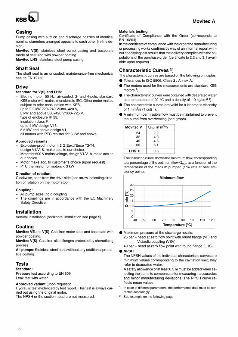
of 1 mm2/s (1 cst) 1).F A minimum permissible flow must be maintained to prevent
the pump from overheating (see graph).
Movitec V Qmin in m3/h
24324565
2.24.04.66.1
LHS 6 0.8
The following curve shows theminimum flow, correspondingto a percentage of the optimum flowQopt, as a function of thetemperature of the medium pumped (flow rate at best effi-ciency point).
F Maximum pressure at the discharge nozzle:25 bar – head at zero flow point with round flange (VF) and
Victaulic coupling (VSV).40 bar – head at zero flow point with round flange (LHS)
F NPSHThe NPSH values of the individual characteristic curves areminimum values corresponding to the cavitation limit; theyrefer to deaerated water.A safety allowance of at least 0.5mmust be addedwhen se-lecting the pump to compensate for measuring inaccuraciesand minor manufacturing deviations. The NPSH curve re-flects mean values.
1) In case of different parameters, the performance data must be cor-rected accordingly.
2) See example on the following page.
Movitec A
9
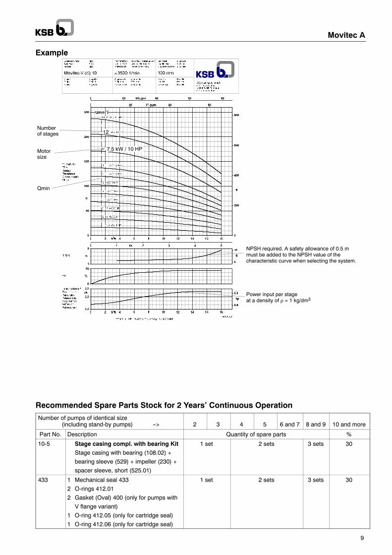
Example
Recommended Spare Parts Stock for 2 Years’ Continuous Operation
Number of pumps of identical size(including stand-by pumps) --> 2 3 4 5 6 and 7 8 and 9 10 and more
Part No. Description Quantity of spare parts %
10-5 Stage casing compl. with bearing Kit
Stage casing with bearing (108.02) +
bearing sleeve (529) + impeller (230) +
spacer sleeve, short (525.01)
1 set 2 sets 3 sets 30
433 1 Mechanical seal 433
2 O-rings 412.01
2 Gasket (Oval) 400 (only for pumps with
V flange variant)
1 O-ring 412.05 (only for cartridge seal)
1 O-ring 412.06 (only for cartridge seal)
1 set 2 sets 3 sets 30
Power input per stageat a density of ρ = 1 kg/dm3
NPSH required. A safety allowance of 0.5 mmust be added to the NPSH value of thecharacteristic curve when selecting the system.
Numberof stages
Motorsize
Qmin
12
7.5 kW / 10 HP
Movitec A
10
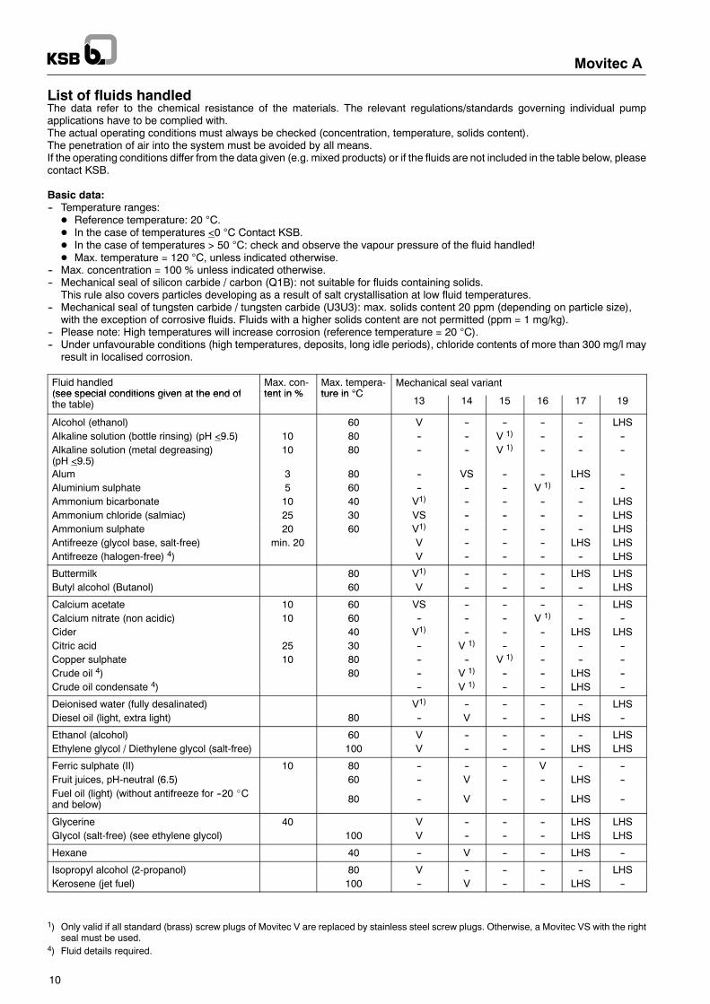
List of fluids handledThe data refer to the chemical resistance of the materials. The relevant regulations/standards governing individual pumpapplications have to be complied with.The actual operating conditions must always be checked (concentration, temperature, solids content).The penetration of air into the system must be avoided by all means.If the operating conditions differ from the data given (e.g. mixed products) or if the fluids are not included in the table below, pleasecontact KSB.
Basic data:-- Temperature ranges:D Reference temperature: 20 °C.D In the case of temperatures <0 °C Contact KSB.D In the case of temperatures > 50 °C: check and observe the vapour pressure of the fluid handled!D Max. temperature = 120 °C, unless indicated otherwise.
-- Max. concentration = 100 % unless indicated otherwise.-- Mechanical seal of silicon carbide / carbon (Q1B): not suitable for fluids containing solids.
This rule also covers particles developing as a result of salt crystallisation at low fluid temperatures.-- Mechanical seal of tungsten carbide / tungsten carbide (U3U3): max. solids content 20 ppm (depending on particle size),
with the exception of corrosive fluids. Fluids with a higher solids content are not permitted (ppm = 1 mg/kg).-- Please note: High temperatures will increase corrosion (reference temperature = 20 °C).-- Under unfavourable conditions (high temperatures, deposits, long idle periods), chloride contents of more than 300 mg/l may
result in localised corrosion.
Fluid handled(see special conditions given at the end of
Max. con-tent in %
Max. tempera-ture in °C
Mechanical seal variant(see special conditions given at the end ofthe table)
tent in % ture in °C13 14 15 16 17 19
Alcohol (ethanol) 60 V -- -- -- -- LHSAlkaline solution (bottle rinsing) (pH <9.5) 10 80 -- -- V 1) -- -- --Alkaline solution (metal degreasing)(pH <9.5)
10 80 -- -- V 1) -- -- --
Alum 3 80 -- VS -- -- LHS --Aluminium sulphate 5 60 -- -- -- V 1) -- --Ammonium bicarbonate 10 40 V1) -- -- -- -- LHSAmmonium chloride (salmiac) 25 30 VS -- -- -- -- LHSAmmonium sulphate 20 60 V1) -- -- -- -- LHSAntifreeze (glycol base, salt-free) min. 20 V -- -- -- LHS LHSAntifreeze (halogen-free) 4) V -- -- -- -- LHS
Buttermilk 80 V1) -- -- -- LHS LHSButyl alcohol (Butanol) 60 V -- -- -- -- LHS
Calcium acetate 10 60 VS -- -- -- -- LHSCalcium nitrate (non acidic) 10 60 -- -- -- V 1) -- --Cider 40 V1) -- -- -- LHS LHSCitric acid 25 30 -- V 1) -- -- -- --Copper sulphate 10 80 -- -- V 1) -- -- --Crude oil 4) 80 -- V 1) -- -- LHS --Crude oil condensate 4) -- V 1) -- -- LHS --
Deionised water (fully desalinated) V1) -- -- -- -- LHSDiesel oil (light, extra light) 80 -- V -- -- LHS --
Ethanol (alcohol) 60 V -- -- -- -- LHSEthylene glycol / Diethylene glycol (salt-free) 100 V -- -- -- LHS LHS
Ferric sulphate (II) 10 80 -- -- -- V -- --Fruit juices, pH-neutral (6.5) 60 -- V -- -- LHS --Fuel oil (light) (without antifreeze for --20 _Cand below) 80 -- V -- -- LHS --
Glycerine 40 V -- -- -- LHS LHSGlycol (salt-free) (see ethylene glycol) 100 V -- -- -- LHS LHS
Hexane 40 -- V -- -- LHS --
Isopropyl alcohol (2-propanol) 80 V -- -- -- -- LHSKerosene (jet fuel) 100 -- V -- -- LHS --
1) Only valid if all standard (brass) screw plugs of Movitec V are replaced by stainless steel screw plugs. Otherwise, a Movitec VS with the rightseal must be used.
4) Fluid details required.
Movitec A
11
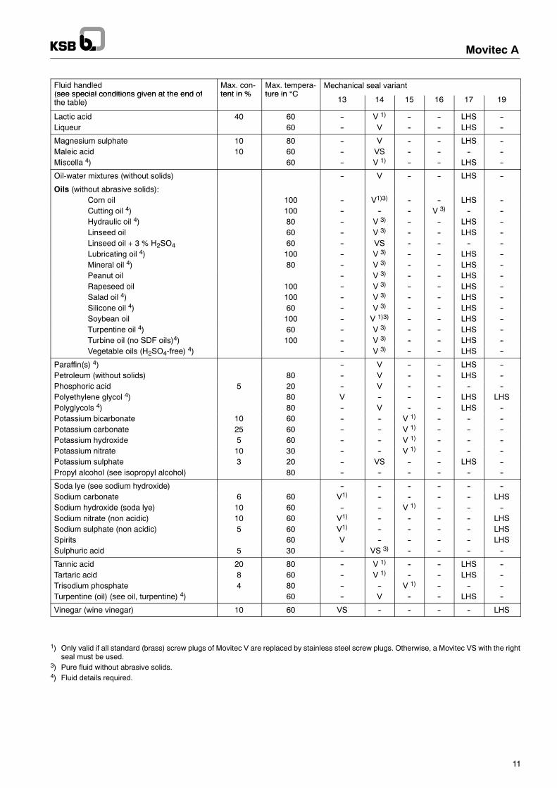
Fluid handled(see special conditions given at the end of
Max. con-tent in %
Max. tempera-ture in °C
Mechanical seal variant(see special conditions given at the end ofthe table)
tent in % ture in °C13 14 15 16 17 19
Lactic acid 40 60 -- V 1) -- -- LHS --Liqueur 60 -- V -- -- LHS --
Magnesium sulphate 10 80 -- V -- -- LHS --Maleic acid 10 60 -- VS -- -- -- --Miscella 4) 60 -- V 1) -- -- LHS --
Oil-water mixtures (without solids) -- V -- -- LHS --
Oils (without abrasive solids):Corn oil 100 -- V1)3) -- -- LHS --Cutting oil 4) 100 -- -- -- V 3) -- --Hydraulic oil 4) 80 -- V 3) -- -- LHS --Linseed oil 60 -- V 3) -- -- LHS --Linseed oil + 3 % H2SO4 60 -- VS -- -- -- --Lubricating oil 4) 100 -- V 3) -- -- LHS --Mineral oil 4) 80 -- V 3) -- -- LHS --Peanut oil -- V 3) -- -- LHS --Rapeseed oil 100 -- V 3) -- -- LHS --Salad oil 4) 100 -- V 3) -- -- LHS --Silicone oil 4) 60 -- V 3) -- -- LHS --Soybean oil 100 -- V 1)3) -- -- LHS --Turpentine oil 4) 60 -- V 3) -- -- LHS --Turbine oil (no SDF oils)4) 100 -- V 3) -- -- LHS --Vegetable oils (H2SO4-free) 4) -- V 3) -- -- LHS --
Paraffin(s) 4) -- V -- -- LHS --Petroleum (without solids) 80 -- V -- -- LHS --Phosphoric acid 5 20 -- V -- -- -- --Polyethylene glycol 4) 80 V -- -- -- LHS LHSPolyglycols 4) 80 -- V -- -- LHS --Potassium bicarbonate 10 60 -- -- V 1) -- -- --Potassium carbonate 25 60 -- -- V 1) -- -- --Potassium hydroxide 5 60 -- -- V 1) -- -- --Potassium nitrate 10 30 -- -- V 1) -- -- --Potassium sulphate 3 20 -- VS -- -- LHS --Propyl alcohol (see isopropyl alcohol) 80 -- -- -- -- -- --
Soda lye (see sodium hydroxide) -- -- -- -- -- --Sodium carbonate 6 60 V1) -- -- -- -- LHSSodium hydroxide (soda lye) 10 60 -- -- V 1) -- -- --Sodium nitrate (non acidic) 10 60 V1) -- -- -- -- LHSSodium sulphate (non acidic) 5 60 V1) -- -- -- -- LHSSpirits 60 V -- -- -- -- LHSSulphuric acid 5 30 -- VS 3) -- -- -- --
Tannic acid 20 80 -- V 1) -- -- LHS --Tartaric acid 8 60 -- V 1) -- -- LHS --Trisodium phosphate 4 80 -- -- V 1) -- -- --Turpentine (oil) (see oil, turpentine) 4) 60 -- V -- -- LHS --
Vinegar (wine vinegar) 10 60 VS -- -- -- -- LHS
1) Only valid if all standard (brass) screw plugs of Movitec V are replaced by stainless steel screw plugs. Otherwise, a Movitec VS with the rightseal must be used.
3) Pure fluid without abrasive solids.4) Fluid details required.

Movitec A
12
Fluid handled(see special conditions given at the end of
Max. con-tent in %
Max. tempera-ture in °C
Mechanical seal variant(see special conditions given at the end ofthe table)
tent in % ture in °C13 14 15 16 17 19
Water-glycol mixture (salt-free, with inhibi-tors) min. 20 V -- -- -- -- LHS
Water:Condensate VS 2) -- -- -- -- LHSCooling water -- -- -- V 1) -- --Decarbonised water -- -- V 1) -- -- --Deionised water V1) -- -- -- -- LHSDistilled water V1) -- -- -- -- LHSDrinking water V -- -- -- -- LHSFire-fighting water -- -- V 1) -- -- --Fully desalinated water (see deionised wa-ter)
-- -- -- -- -- --
Heating water V -- -- -- -- LHSPartly desalinated water (see decarbonisedwater)
-- -- -- -- -- --
Pure water (chemically neutral, no ultrapurewater) V1) -- -- -- -- LHS
Rinsing water -- -- -- V 1) -- --Seawater (continuous operation) 25 -- -- -- VS -- --Softened water (see decarbonised water) -- -- -- -- -- --Swimming pool water (no brine) -- VS -- -- LHS --Untreated water(suspended solids content < 20 ppm)
-- -- V -- -- --
Tap water V -- -- -- -- LHSWine (white, red) 40 V1) -- -- -- LHS LHS
1) Only valid if all standard (brass) screw plugs of Movitec V are replaced by stainless steel screw plugs. Otherwise, a Movitec VS with the rightseal must be used.
2) Water treatment shall be in accordance with VdTÜV guidelines for feed and boiler water in steam systems of up to 64 bar.The penetration of air into the system must be avoided by all means.

Movitec A
13
Movitec V with standard KSB motor 3~230/400 V
Pump size Numberofstages
Sealcode
Motorrating
Ratedcurrent
Oval flangeMovitec V
Round flangeMovitec VF
Victaulic couplingMovitec VV
kW Inom in A Ident No. kg Ident No. kg Ident No. kg
4 poles
Movitec V 24 1 13 1.1 4.8 / 2.8 -- -- 47 110 084 56.8 -- --Movitec V 24 2 13 1.5 6.5 / 3.7 -- -- 47 110 085 61.6 -- --Movitec V 24 3 13 2.2 8.4 / 4.9 -- -- 47 110 086 72.5 -- --Movitec V 24 4 13 3 14.5 / 8.4 -- -- 47 110 087 75.8 -- --Movitec V 24 5 13 4 17.5 / 10.1 -- -- 47 110 088 86.2 -- --Movitec V 24 6 13 5.5 19.8 / 11.5 -- -- 47 110 089 122.1 -- --Movitec V 24 7 13 5.5 19.8 / 11.5 -- -- 47 110 090 124.4 -- --Movitec V 24 8 13 7.5 27.0 / 15.6 -- -- 47 110 091 137.8 -- --Movitec V 24 9 13 7.5 27.0 / 15.6 -- -- 47 110 092 140.1 -- --Movitec V 24 10 13 7.5 27.0 / 15.6 -- -- 47 110 093 142.5 -- --Movitec V 24 11 11 7.5 27.0 / 15.6 -- -- 47 110 094 144.8 -- --Movitec V 24 12 13 11 44.0 / 25.3 -- -- 47 110 095 194.8 -- --Movitec V 24 16 13 15 57.4 / 33.0 -- -- 47 110 096 216.2 -- --
2 poles
Movitec V 32 1 13 3 12.4 / 7.2 -- -- 47 110 120 69.9 -- --Movitec V 32 2 13 7.5 26.8 / 15.5 -- -- 47 110 121 91.2 -- --Movitec V 32 3 13 11 53.7 / 31.0 -- -- 47 110 122 162.5 -- --Movitec V 32 4 13 15 56.3 / 32.5 -- -- 47 110 123 178.8 -- --Movitec V 32 5 13 15 56.3 / 32.5 -- -- 47 110 124 181.1 -- --Movitec V 32 6 13 18.5 72.1 / 41.6 -- -- 47 110 125 198.4 -- --Movitec V 32 7 13 22 78.8 / 45.5 -- -- 47 110 126 236.7 -- --
Movitec V 45 1--1 13 3 12.4 / 7.2 -- -- 47 110 160 70.9 -- --Movitec V 45 1 13 5.5 21.0 / 12.1 -- -- 47 110 161 86.0 -- --Movitec V 45 2--1 13 11 53.7 / 31.0 -- -- 47 110 162 161.3 -- --Movitec V 45 2 13 11 53.7 / 31.0 -- -- 47 110 163 161.4 -- --Movitec V 45 3--1 13 15 56.3 / 32.5 -- -- 47 110 164 177.7 -- --Movitec V 45 3 13 18.5 72.1 / 41.6 -- -- 47 110 165 192.8 -- --Movitec V 45 4--1 13 22 78.8 / 45.5 -- -- 47 110 166 230.9 -- --
Movitec V 65 1 13 5.5 21.0 / 12.1 -- -- 47 110 185 93.1 -- --Movitec V 65 2 13 11 53.7 / 31.0 -- -- 47 110 186 166.7 -- --Movitec V 65 3 13 15 56.3 / 32.5 -- -- 47 110 187 184.1 -- --Movitec V 65 4 13 18.5 72.1 / 41.6 -- -- 47 110 188 202.5 -- --Movitec V 65 5 13 22 78.8 / 45.5 -- -- 47 110 189 241.9 -- --
Movitec A
14
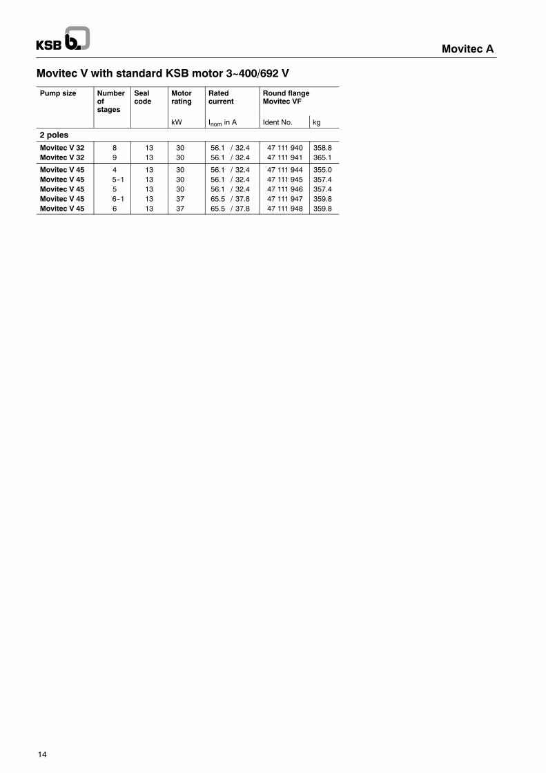
Movitec V with standard KSB motor 3~400/692 V
Pump size Numberofstages
Sealcode
Motorrating
Ratedcurrent
Round flangeMovitec VF
kW Inom in A Ident No. kg
2 poles
Movitec V 32 8 13 30 56.1 / 32.4 47 111 940 358.8Movitec V 32 9 13 30 56.1 / 32.4 47 111 941 365.1
Movitec V 45 4 13 30 56.1 / 32.4 47 111 944 355.0Movitec V 45 5--1 13 30 56.1 / 32.4 47 111 945 357.4Movitec V 45 5 13 30 56.1 / 32.4 47 111 946 357.4Movitec V 45 6--1 13 37 65.5 / 37.8 47 111 947 359.8Movitec V 45 6 13 37 65.5 / 37.8 47 111 948 359.8
Movitec A
15
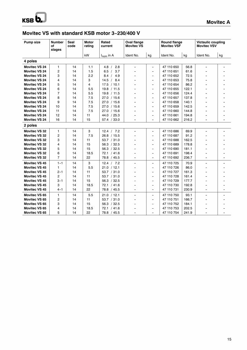
Movitec VS with standard KSB motor 3~230/400 V
Pump size Numberofstages
Sealcode
Motorrating
Ratedcurrent
Oval flangeMovitec VS
Round flangeMovitec VSF
Victaulic couplingMovitec VSV
kW Inom in A Ident No. kg Ident No. kg Ident No. kg
4 poles
Movitec VS 24 1 14 1.1 4.8 / 2.8 -- -- 47 110 650 56.8 -- --Movitec VS 24 2 14 1.5 6.5 / 3.7 -- -- 47 110 651 61.6 -- --Movitec VS 24 3 14 2.2 8.4 / 4.9 -- -- 47 110 652 72.5 -- --Movitec VS 24 4 14 3 14.5 / 8.4 -- -- 47 110 653 75.8 -- --Movitec VS 24 5 14 4 17.5 / 10.1 -- -- 47 110 654 86.2 -- --Movitec VS 24 6 14 5.5 19.8 / 11.5 -- -- 47 110 655 122.1 -- --Movitec VS 24 7 14 5.5 19.8 / 11.5 -- -- 47 110 656 124.4 -- --Movitec VS 24 8 14 7.5 27.0 / 15.6 -- -- 47 110 657 137.8 -- --Movitec VS 24 9 14 7.5 27.0 / 15.6 -- -- 47 110 658 140.1 -- --Movitec VS 24 10 14 7.5 27.0 / 15.6 -- -- 47 110 659 142.5 -- --Movitec VS 24 11 14 7.5 27.0 / 15.6 -- -- 47 110 660 144.8 -- --Movitec VS 24 12 14 11 44.0 / 25.3 -- -- 47 110 661 194.8 -- --Movitec VS 24 16 14 15 57.4 / 33.0 -- -- 47 110 662 216.2 -- --
2 poles
Movitec VS 32 1 14 3 12.4 / 7.2 -- -- 47 110 686 69.9 -- --Movitec VS 32 2 14 7.5 26.8 / 15.5 -- -- 47 110 687 91.2 -- --Movitec VS 32 3 14 11 53.7 / 31.0 -- -- 47 110 688 162.5 -- --Movitec VS 32 4 14 15 56.3 / 32.5 -- -- 47 110 689 178.8 -- --Movitec VS 32 5 14 15 56.3 / 32.5 -- -- 47 110 690 181.1 -- --Movitec VS 32 6 14 18.5 72.1 / 41.6 -- -- 47 110 691 198.4 -- --Movitec VS 32 7 14 22 78.8 / 45.5 -- -- 47 110 692 236.7 -- --
Movitec VS 45 1--1 14 3 12.4 / 7.2 -- -- 47 110 725 70.9 -- --Movitec VS 45 1 14 5.5 21.0 / 12.1 -- -- 47 110 726 86.0 -- --Movitec VS 45 2--1 14 11 53.7 / 31.0 -- -- 47 110 727 161.3 -- --Movitec VS 45 2 14 11 53.7 / 31.0 -- -- 47 110 728 161.4 -- --Movitec VS 45 3--1 14 15 56.3 / 32.5 -- -- 47 110 729 177.7 -- --Movitec VS 45 3 14 18.5 72.1 / 41.6 -- -- 47 110 730 192.8 -- --Movitec VS 45 4--1 14 22 78.8 / 45.5 -- -- 47 110 731 230.9 -- --
Movitec VS 65 1 14 5.5 21.0 / 12.1 -- -- 47 110 750 93.1 -- --Movitec VS 65 2 14 11 53.7 / 31.0 -- -- 47 110 751 166.7 -- --Movitec VS 65 3 14 15 56.3 / 32.5 -- -- 47 110 752 184.1 -- --Movitec VS 65 4 14 18.5 72.1 / 41.6 -- -- 47 110 753 202.5 -- --Movitec VS 65 5 14 22 78.8 / 45.5 -- -- 47 110 754 241.9 -- --

Movitec A
16
Movitec VS with standard KSB motor 3~400/692 V
Pump size Numberofstages
Sealcode
Motorrating
Ratedcurrent
Round flangeMovitec VSF
kW Inom in A Ident No. kg
2 poles
Movitec VS 32 8 14 30 56.1 / 32.4 47 111 942 358.8Movitec VS 32 9 14 30 56.1 / 32.4 47 111 943 365.1
Movitec VS 45 4 14 30 56.1 / 32.4 47 111 949 355.0Movitec VS 45 5--1 14 30 56.1 / 32.4 47 111 950 357.4Movitec VS 45 5 14 30 56.1 / 32.4 47 111 951 357.4Movitec VS 45 6--1 14 37 65.5 / 37.8 47 111 952 359.8Movitec VS 45 6 14 37 65.5 / 37.8 47 111 953 359.8
Movitec A
17
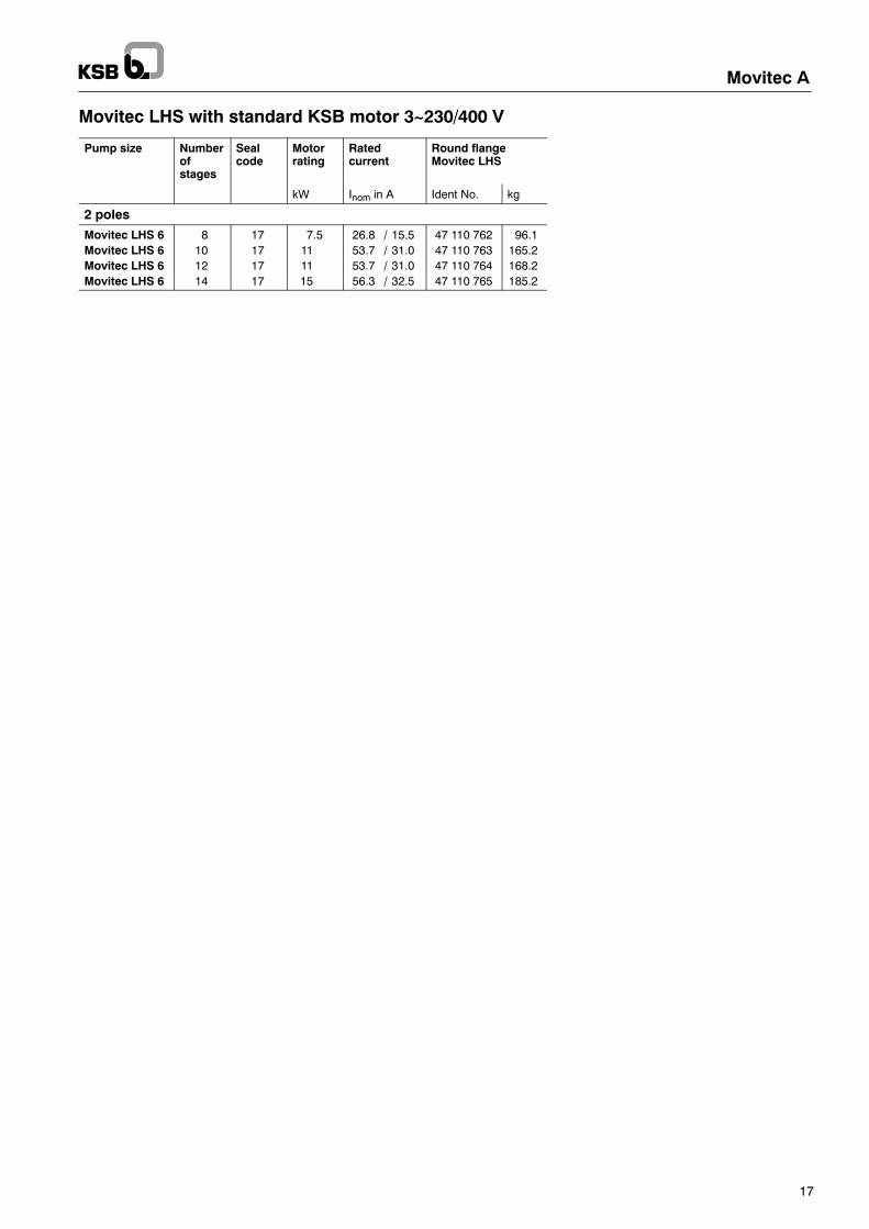
Movitec LHS with standard KSB motor 3~230/400 V
Pump size Numberofstages
Sealcode
Motorrating
Ratedcurrent
Round flangeMovitec LHS
kW Inom in A Ident No. kg
2 poles
Movitec LHS 6 8 17 7.5 26.8 / 15.5 47 110 762 96.1Movitec LHS 6 10 17 11 53.7 / 31.0 47 110 763 165.2Movitec LHS 6 12 17 11 53.7 / 31.0 47 110 764 168.2Movitec LHS 6 14 17 15 56.3 / 32.5 47 110 765 185.2
18
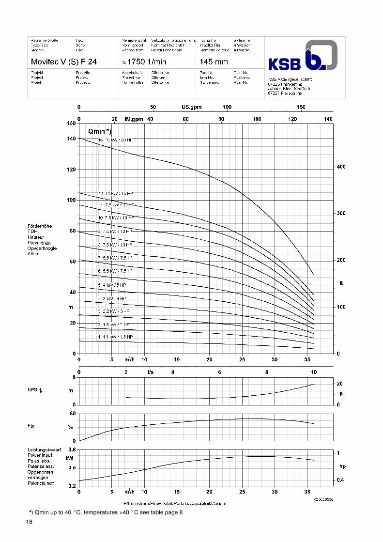
*) Qmin up to 40 _C, temperatures >40 _C see table page 8

19
*) Qmin up to 40 _C, temperatures >40 _C see table page 8
20
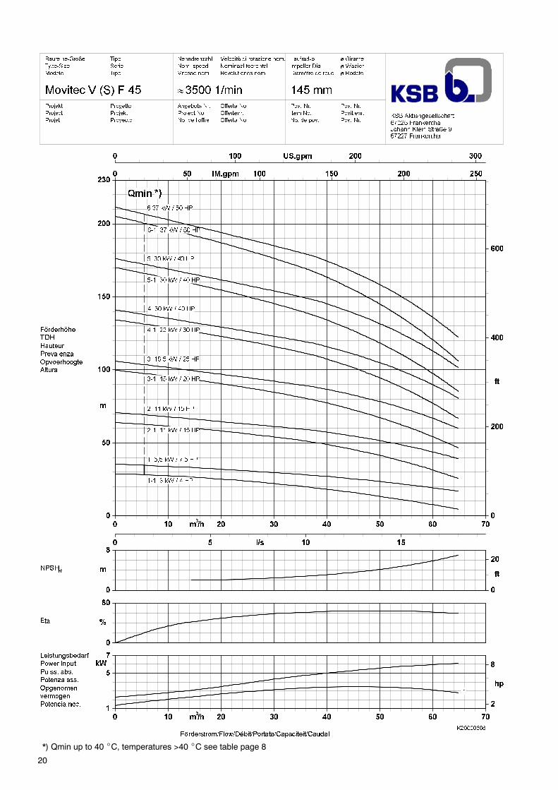
*) Qmin up to 40 _C, temperatures >40 _C see table page 8

21
*) Qmin up to 40 _C, temperatures >40 _C see table page 8

22
*) Qmin up to 40 _C, temperatures >40 _C see table page 8

Movitec A
23
Dimension TablesMovitec VF 24 1750 1/min
VF 24
No. of stages E1 E2 F1 F2
1 176 136 738 458
2 176 136 786 506
3 194 147 871 555
4 194 147 919 603
5 233 162 976 652
6 266 179 1103 720
7 266 179 1152 769
8 266 179 1238 817
9 266 179 1287 866
10 266 179 1335 914
11 266 179 1384 963
12 312 230 1553 1116
16 312 230 1787 1310
Dimensions in mm
Flange Variants
Round flange PN 25Movitec V(S) F
Terminal Box Position for all pump sizes see page 28

Movitec A
24
Dimension TablesMovitec VF 32 3500 1/min
VF 32
No. of stages E1 E2 F1 F2
1 194 147 774 458
2 233 162 883 526
3 315 206 1182 680
4 315 206 1230 728
5 315 206 1279 777
6 315 206 1371 825
7 350 225 1469 874
8 398 323 1572 922
9 398 323 1621 971
Dimensions in mm
Flange Variants
Round flange PN 25Movitec V(S) F
Terminal Box Position for all pump sizes see page 28
Movitec A
25
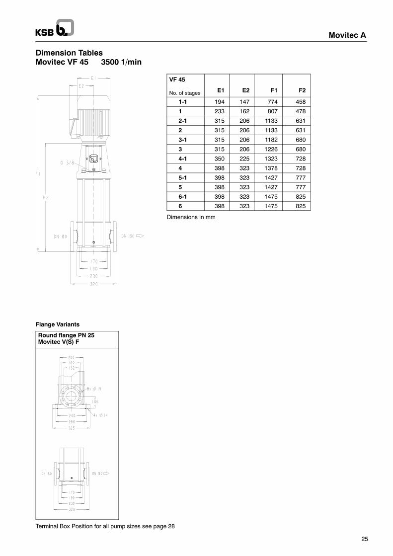
Dimension TablesMovitec VF 45 3500 1/min
VF 45
No. of stages E1 E2 F1 F2
1-1 194 147 774 458
1 233 162 807 478
2-1 315 206 1133 631
2 315 206 1133 631
3-1 315 206 1182 680
3 315 206 1226 680
4-1 350 225 1323 728
4 398 323 1378 728
5-1 398 323 1427 777
5 398 323 1427 777
6-1 398 323 1475 825
6 398 323 1475 825
Dimensions in mm
Flange Variants
Round flange PN 25Movitec V(S) F
Terminal Box Position for all pump sizes see page 28

Movitec A
26
Dimension TablesMovitec VF 65 3500 1/min
VF 65Round flanges
PN 16
No. of stages E1 E2 F1 F2
1 233 162 919 590
2 315 206 1211 709
3 315 206 1300 798
4 315 206 1433 887
5 350 225 1571 976
Dimensions in mm
Flange Variants
Round flanges PN 16
Terminal Box Position for all pump sizes see page 28

Position of the terminal box(viewed from above)
Position 3(Standard Movitec V, VS, LHS)
Position 6
Position 9
Position 12
Movitec A
27
Dimension TablesMovitec LHS 6 3500 1/min
LHS 6
No. of stages E1 E2 F1 F2
8 233 162 896 539
10 315 206 1131 629
12 315 206 1190 688
14 315 206 1250 748
Dimensions in mm
Terminal Box Position for all Pump Sizes
Flange Variants
Round flange PN 40

20010712--E
Movitec A
28
Sectional DrawingMovitec VF 24, 32, 45

Detail cartridge seal
Movitec A
29
Part No. Description
10-6 Pump shroud101 Pump casing108.04 Stage casing, bottom160 Cover171.01 Diffuser171.02 Diffuser, with ceramic bearing171.03 Diffuser, upper210 Shaft230 Impeller (for Movitec VF 24 and 32)230.01 Impeller (for Movitec VF 45)230.02 Impeller, half head (for Movitec VF 45)341 Motor stool411.01 Joint ring412.01 O-ring412.02 O-ring412.03 O-ring412.04 O-ring412.05 O-ring412.06 O-ring433 Mechanical seal471 Seal cover500 Ring, cartridge509.01 Intermediate ring509.02 Intermediate ring, upper525.01 Spacer sleeve, short525.03 Spacer sleeve, long525.04 Spacer sleeve, end525.05 Spacer sleeve, seal525.06 Spacer sleeve, seal extention525.07 Spacer sleeve, cartridge529 Bearing sleeve554.01 Washer560 Pin681 Coupling guard800 Motor (> 5,5 kW 801 Flange motor)862 Coupling shell890 Baseplate, cast901.01 Hexagon head bolt903.01 Screwed plug903.02 Screwed plug904 Grub screw905 Tie bolt914.01 Hexagon socket head cap screw914.02 Hexagon socket head cap screw914.03 Hexagon socket head cap screw920.01 Nut920.02 Nut, lock with non metallic insert920.03 Nut930 Safety device, nord-lock932 Circlip (1/2)
20000752--F
Movitec A
30
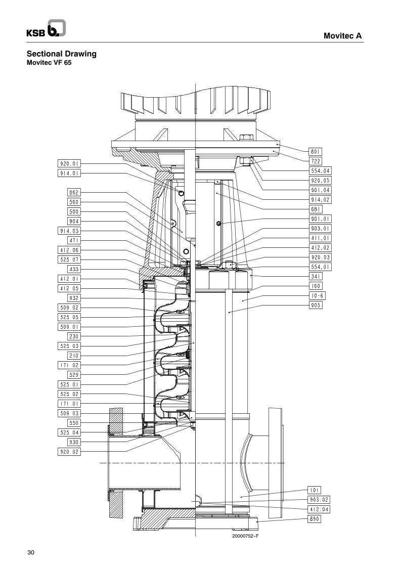
Sectional DrawingMovitec VF 65

Movitec A
31
Part No. Description
10-6 Pump shroud101 Pump casing160 Cover171.01 Diffuser171.02 Diffuser, with ceramic bearing210 Shaft230 Impeller341 Motor stool411.01 Joint ring412.01 O-ring412.02 O-ring412.04 O-ring412.05 O-ring412.06 O-ring433 Mechanical seal471 Seal cover500 RingCartridge509.01 Intermediate ring509.02 Intermediate ring, upper509.03 Intermediate ring, lower525.01 Spacer sleeve, short525.02 Spacer sleeve, middle525.03 Spacer sleeve, long525.04 Spacer sleeve, end525.05 Spacer sleeve, seal525.07 Spacer sleeve, cartridge529 Bearing sleeve550 Disc Bottom554.01 Washer554.04 Washer560 Pin681 Coupling guard722 Tap piece, flanged801 Flange motor862 Coupling shell890 Baseplate, cast901.01 Hexagon head bolt901.04 Hexagon head bolt903.01 Screwed plug903.02 Screwed plug904 Grub screw905 Tie bolt914.01 Hexagon socket head cap screw914.02 Hexagon socket head cap screw914.03 Hexagon socket head cap screw920.01 Nut920.02 Nut lock with non metallic insert920.03 Nut920.05 Nut930 Safety device, nord-lock932 Circlip (1/2)

20030238--B
Movitec A
32
Sectional DrawingMovitec LHS 6

Movitec A
33
Part No. Description
10-6 Pump shroud101 Pump casing108.01 Stage casing108.02 Stage casing with ceramic bearing108.04 Stage casing, bottom108.05 Stage casing, upper210 Shaft230 Impeller341 Motor stool411.01 Joint ring411.04 Joint ring412.01 O-ring412.03 O-ring433 Mechanical seal525.01 Spacer sleeve, short525.02 Spacer sleeve, middle525.03 Spacer sleeve, long525.04 Spacer sleeve, end525.05 Spacer sleeve, seal529 Bearing sleeve554.01 Washer554.02 Washer554.04 Washer560 Pin681 Coupling guard722 Tap piece, flanged801 Motor862 Coupling shell901.01 Hexagon head bolt901.02 Hexagon head bolt901.04 Hexagon head bolt903.01 Screwed plug903.02 Screwed plug905 Tie bolt914.01 Hexagon socket head cap screw920.01 Nut920.02 Nut lock with non metallic insert920.03 Nut920.05 Nut930 Safety device nord-lock932 Circlip

Movitec A
34

Movitec A
35

1798.56/4-10
Subjecttotechnicalm
odifications
withoutpriornotice.
1.2.2011
Movitec A
KSB Aktiengesellschaft67225 Frankenthal • Johann-Klein-Str. 9 • 67227 Frankenthal (Germany)Tel. +49 6233 86-0 • Fax +49 6233 86-3401 • www.ksb.com