MOVIAXIS® MX Functional Safety / Manuals / 2012-06 · PDF fileDrive Technology \ Drive...
48
Drive Technology \ Drive Automation \ System Integration \ Services Manual MOVIAXIS ® Multi-Axis Servo Inverter Functional Safety Edition 06/2012 19304412 / EN
Transcript of MOVIAXIS® MX Functional Safety / Manuals / 2012-06 · PDF fileDrive Technology \ Drive...
Drive Technology \ Drive Automation \ System Integration \ Services
Manual
MOVIAXIS® Multi-Axis Servo InverterFunctional Safety
Edition 06/2012 19304412 / EN
SEW-EURODRIVE—Driving the world
Contents
Contents1 General Information ............................................................................................ 5
1.1 How to use this documentation................................................................... 51.2 Underlying standards .................................................................................. 51.3 Structure of the safety notes ....................................................................... 6
1.3.1 Meaning of signal words .............................................................. 61.3.2 Structure of the section-related safety notes ............................... 61.3.3 Structure of the embedded safety notes...................................... 6
1.4 Rights to claim under limited warranty ........................................................ 61.5 Exclusion of liability..................................................................................... 61.6 Copyright..................................................................................................... 71.7 Product names and trademarks.................................................................. 71.8 Contents of this publication......................................................................... 71.9 Other applicable documentation ................................................................. 7
2 Integrated Safety Technology............................................................................ 82.1 Safe condition ............................................................................................. 82.2 Safety concept ............................................................................................ 8
2.2.1 Safety inputs ................................................................................ 92.3 Safety functions ........................................................................................ 102.4 Restrictions ............................................................................................... 12
3 Safety Conditions.............................................................................................. 133.1 General information .................................................................................. 133.2 Permitted unit combinations and connection variants............................... 14
3.2.1 Units with one safety relay......................................................... 143.2.2 Units with two safety relays ....................................................... 143.2.3 Status line on the nameplate ..................................................... 15
3.3 Requirements on the installation............................................................... 163.3.1 Freewheeling diode ................................................................... 163.3.2 Wiring instructions for PL d according to EN ISO 13849-1........ 173.3.3 Wiring instructions for protection type III according to
EN 201, PL e according to EN ISO 13849-1, SIL 3 according to IEC 61800-5-2....................................................... 18
3.4 Requirements on external safety controllers/safety relays ....................... 193.5 Requirements on startup........................................................................... 203.6 Requirements on operation....................................................................... 20
Functional Safety – MOVIAXIS® Multi-Axis Servo Inverter
3
4
Contents
4 Connection Variants ......................................................................................... 214.1 General information .................................................................................. 21
4.1.1 MOVIAXIS® axis system ........................................................... 214.1.2 Connections of the safety relays................................................ 22
4.2 Requirements............................................................................................ 234.2.1 Using safety relays .................................................................... 234.2.2 Using PLC FDOs ....................................................................... 23
4.3 Disconnection of a single drive ................................................................. 244.3.1 STO according to PL d (EN ISO 13849-1)................................. 244.3.2 SS1 according to PL d (EN ISO 13849-1) ................................. 274.3.3 STO according to PL e (EN ISO 13849-1)................................. 304.3.4 SS1 according to PL e (EN ISO 13849-1) ................................. 32
4.4 Disconnection of group drives................................................................... 344.4.1 Requirements ............................................................................ 344.4.2 Implementing group disconnection with safety relay ................. 354.4.3 STO according to PL d (EN ISO 13849-1)................................. 364.4.4 STO according to PL e (EN ISO 13849-1)................................. 38
5 Technical Data................................................................................................... 405.1 Safety characteristics................................................................................ 41
5.1.1 Safety characteristics with one safety relay............................... 415.1.2 Safety characteristics with two safety relays ............................. 41
Index................................................................................................................... 42
Functional Safety – MOVIAXIS® Multi
-Axis Servo Inverter
1How to use this documentationGeneral Information
MOVIAXIS® Multi-Axis Servo Inverter1 General Information1.1 How to use this documentation
This manual "MOVIAXIS® Multi-Axis Servo Inverter – Functional Safety" contains spe-cial information on MOVIAXIS® multi-axis servo inverters that perform safety functions.
Documentation for a MOVIAXIS® multi-axis servo inverter that performs safety functionscomprises the following publications:
• "MOVIAXIS® Multi-Axis Servo Inverter" operating instructions
• "MOVIAXIS® Multi-Axis Servo Inverter – Functional Safety" manual
The operating instructions and the manual are an integral part of the product and containimportant information for operation and service. The operating instructions and the man-ual are intended for staff responsible for the assembly, installation, startup and mainte-nance of the product.
The operating instructions and the manual must be legible and accessible at all times.Make sure that staff responsible for the plant and its operation as well as persons whowork independently on the unit have read the operating instructions carefully and under-stood them. If you are unclear about any of the information in this documentation, or ifyou require further information, contact SEW-EURODRIVE.
Make sure you always use the latest documentation and software version.
Our documentation is available in various languages for download from the SEWhomepage (www.sew-eurodrive.com). Consult SEW-EURODRIVE if you are unclearabout any of the information in this documentation, or if you require further information.
You can also order the printed documentation from SEW-EURODRIVE.
1.2 Underlying standardsThe safety assessment of the MOVIAXIS® multi-axis servo inverter is based on the fol-lowing standards and safety classes:
Underlying standard for MOVIAXIS® MXA81A
Safety class/underlying standard • Performance Level (PL) according to EN ISO 13849-1: 2006
Underlying standard for MOVIAXIS® MXA82A
Safety class/underlying standard• Performance Level (PL) according to EN ISO 13849-1: 2006• Safety Integrity Level (SIL) according to EN 61800-5-2: 2007• Protection type according to EN 201: 1997
Functional Safety – MOVIAXIS® Multi-Axis Servo Inverter
5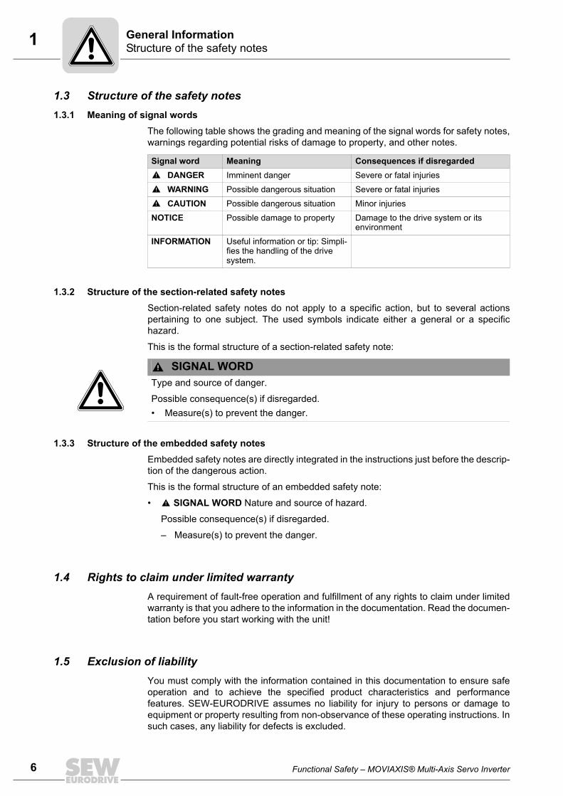
6
1 tructure of the safety noteseneral Information
1.3 Structure of the safety notes1.3.1 Meaning of signal words
The following table shows the grading and meaning of the signal words for safety notes,warnings regarding potential risks of damage to property, and other notes.
1.3.2 Structure of the section-related safety notesSection-related safety notes do not apply to a specific action, but to several actionspertaining to one subject. The used symbols indicate either a general or a specifichazard.
This is the formal structure of a section-related safety note:
1.3.3 Structure of the embedded safety notesEmbedded safety notes are directly integrated in the instructions just before the descrip-tion of the dangerous action.
This is the formal structure of an embedded safety note:
• SIGNAL WORD Nature and source of hazard.
Possible consequence(s) if disregarded.
– Measure(s) to prevent the danger.
1.4 Rights to claim under limited warrantyA requirement of fault-free operation and fulfillment of any rights to claim under limitedwarranty is that you adhere to the information in the documentation. Read the documen-tation before you start working with the unit!
1.5 Exclusion of liabilityYou must comply with the information contained in this documentation to ensure safeoperation and to achieve the specified product characteristics and performancefeatures. SEW-EURODRIVE assumes no liability for injury to persons or damage toequipment or property resulting from non-observance of these operating instructions. Insuch cases, any liability for defects is excluded.
Signal word Meaning Consequences if disregardedDANGER Imminent danger Severe or fatal injuries
WARNING Possible dangerous situation Severe or fatal injuries
CAUTION Possible dangerous situation Minor injuries
NOTICE Possible damage to property Damage to the drive system or its environment
INFORMATION Useful information or tip: Simpli-fies the handling of the drive system.
SIGNAL WORDType and source of danger.
Possible consequence(s) if disregarded.• Measure(s) to prevent the danger.
SG
Functional Safety – MOVIAXIS® Multi-Axis Servo Inverter
1CopyrightGeneral Information
1.6 Copyright© 2012 – SEW-EURODRIVE. All rights reserved.
Unauthorized duplication, modification, distribution or any other use of the whole or anypart of this documentation is strictly prohibited.
1.7 Product names and trademarksAll product names in this documentation are trademarks or registered trademarks oftheir respective titleholders.
1.8 Contents of this publicationThis publication contains conditions and amendments concerning safety-related appli-cations.
1.9 Other applicable documentationThis document supplements the MOVIAXIS® multi-axis servo inverter operating instruc-tions and limits the application notes according to the following information.
The document in hand must be used together with the "MOVIAXIS® Multi-Axis ServoInverter" operating instructions.
INFORMATIONCompare the data in the status line of the nameplate with the information in chapter"Permitted devices" (page 14).
Functional Safety – MOVIAXIS® Multi-Axis Servo Inverter
7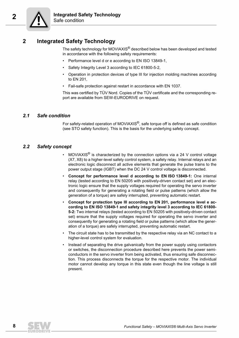
8
2 afe conditiontegrated Safety Technology
2 Integrated Safety TechnologyThe safety technology for MOVIAXIS® described below has been developed and testedin accordance with the following safety requirements:
• Performance level d or e according to EN ISO 13849-1,
• Safety Integrity Level 3 according to IEC 61800-5-2,
• Operation in protection devices of type III for injection molding machines accordingto EN 201,
• Fail-safe protection against restart in accordance with EN 1037.
This was certified by TÜV Nord. Copies of the TÜV certificate and the corresponding re-port are available from SEW-EURODRIVE on request.
2.1 Safe conditionFor safety-related operation of MOVIAXIS®, safe torque off is defined as safe condition(see STO safety function). This is the basis for the underlying safety concept.
2.2 Safety concept• MOVIAXIS® is characterized by the connection options via a 24 V control voltage
(X7, X8) to a higher-level safety control system, a safety relay. Internal relays and anelectronic logic disconnect all active elements that generate the pulse trains to thepower output stage (IGBT) when the DC 24 V control voltage is disconnected.
• Concept for performance level d according to EN ISO 13849-1: One internalrelay (tested according to EN 50205 with positively-driven contact set) and an elec-tronic logic ensure that the supply voltages required for operating the servo inverterand consequently for generating a rotating field or pulse patterns (which allow thegeneration of a torque) are safely interrupted, preventing automatic restart.
• Concept for protection type III according to EN 201, performance level e ac-cording to EN ISO 13849-1 and safety integrity level 3 according to IEC 61800-5-2: Two internal relays (tested according to EN 50205 with positively-driven contactset) ensure that the supply voltages required for operating the servo inverter andconsequently for generating a rotating field or pulse patterns (which allow the gener-ation of a torque) are safely interrupted, preventing automatic restart.
• The circuit state has to be transmitted by the respective relay via an NC contact to ahigher-level control system for evaluation.
• Instead of separating the drive galvanically from the power supply using contactorsor switches, the disconnection procedure described here prevents the power semi-conductors in the servo inverter from being activated, thus ensuring safe disconnec-tion. This process disconnects the torque for the respective motor. The individualmotor cannot develop any torque in this state even though the line voltage is stillpresent.
SIn
Functional Safety – MOVIAXIS® Multi-Axis Servo Inverter
2Safety conceptIntegrated Safety Technology
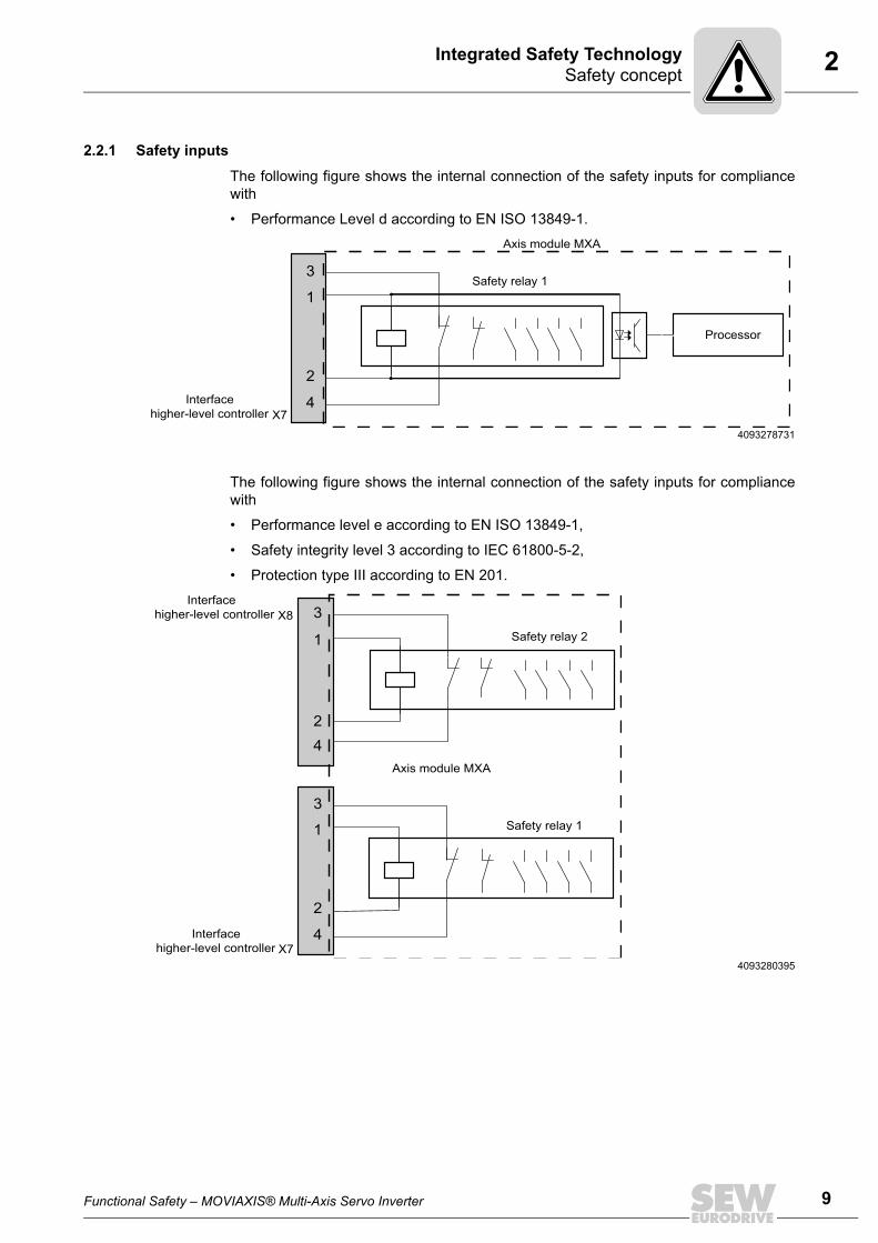
2.2.1 Safety inputs
The following figure shows the internal connection of the safety inputs for compliancewith
• Performance Level d according to EN ISO 13849-1.
The following figure shows the internal connection of the safety inputs for compliancewith
• Performance level e according to EN ISO 13849-1,
• Safety integrity level 3 according to IEC 61800-5-2,
• Protection type III according to EN 201.
4093278731
Safety relay 1
Interfacehigher-level controller
1
2
3
4X7
Axis module MXA
Processor
4093280395
Interface higher-level controller
Safety relay 2
Safety relay 1
Interfacehigher-level controller
1
2
3
4
1
2
3
4
X8
X7
Axis module MXA
Functional Safety – MOVIAXIS® Multi-Axis Servo Inverter
9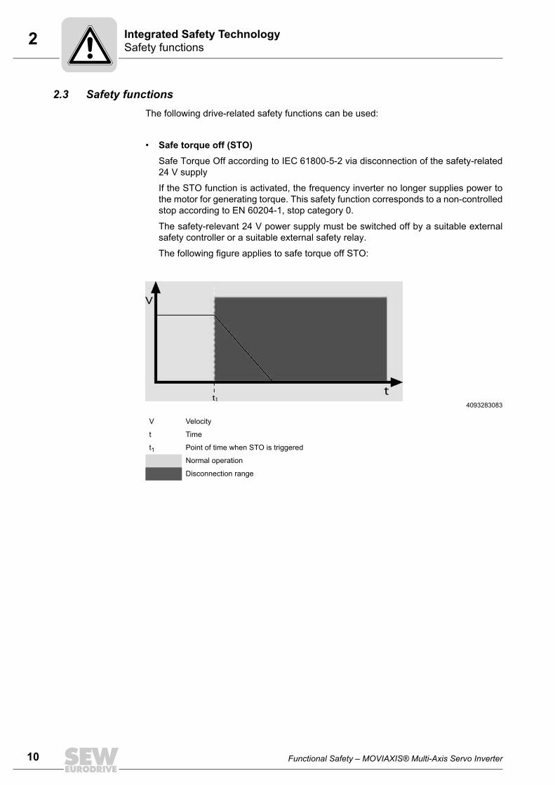
10
2 afety functionstegrated Safety Technology
2.3 Safety functionsThe following drive-related safety functions can be used:
• Safe torque off (STO)Safe Torque Off according to IEC 61800-5-2 via disconnection of the safety-related24 V supply
If the STO function is activated, the frequency inverter no longer supplies power tothe motor for generating torque. This safety function corresponds to a non-controlledstop according to EN 60204-1, stop category 0.
The safety-relevant 24 V power supply must be switched off by a suitable externalsafety controller or a suitable external safety relay.
The following figure applies to safe torque off STO:
4093283083
V Velocity
t Time
t1 Point of time when STO is triggered
Normal operation
Disconnection range
SIn
Functional Safety – MOVIAXIS® Multi-Axis Servo Inverter
2Safety functionsIntegrated Safety Technology
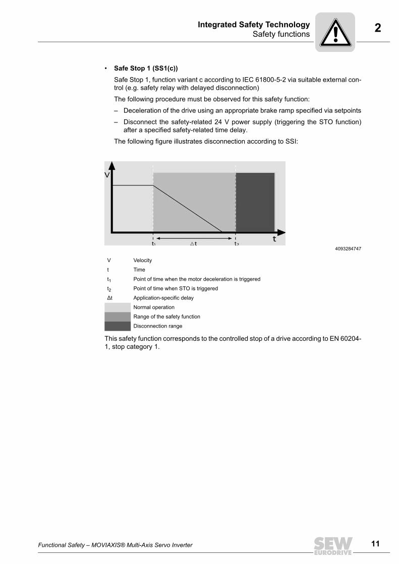
• Safe Stop 1 (SS1(c))Safe Stop 1, function variant c according to IEC 61800-5-2 via suitable external con-trol (e.g. safety relay with delayed disconnection)
The following procedure must be observed for this safety function:
– Deceleration of the drive using an appropriate brake ramp specified via setpoints
– Disconnect the safety-related 24 V power supply (triggering the STO function)after a specified safety-related time delay.
The following figure illustrates disconnection according to SSI:
This safety function corresponds to the controlled stop of a drive according to EN 60204-1, stop category 1.
4093284747
V Velocity
t Time
t1 Point of time when the motor deceleration is triggered
t2 Point of time when STO is triggered
∆t Application-specific delay
Normal operation
Range of the safety function
Disconnection range
Functional Safety – MOVIAXIS® Multi-Axis Servo Inverter
11
12
2 estrictionstegrated Safety Technology
2.4 Restrictions• Important: When using the SS1(c) function as described above, the brake ramp of
the drive is not monitored with respect to safety. In case of a fault, the drive might notbe decelerated after the delay time, or it might be accelerated in the worst case. Inthis case, the STO function (see above) is only activated after the set time delay haspassed. You have to take the resulting danger into account when you perform therisk assessment for the plant/machine, and you have to provide for suitable precau-tionary measures if required.
• Important: A system/machine-specific risk assessment must be carried out by thesystem/machine manufacturer and taken into account for using the drive system withMOVIAXIS®.
• Important: The safety concept is only suitable for performing mechanical workon the system/machine components.
• Danger of fatal injury: When the 24 V supply voltage is disconnected, the mainssupply voltage is still present at the frequency inverter's DC link.
• Important: If work is carried out on the electrical section of the drive system,the supply voltage must be disconnected using an external maintenanceswitch.
RIn
Functional Safety – MOVIAXIS® Multi-Axis Servo Inverter
3General informationSafety Conditions
3 Safety Conditions3.1 General information
The safety functions of MOVIAXIS® can only be used for safe operation of thesystem/machine if they are integrated correctly in an application-specific, higher-levelsafety function or safety system. For this purpose, it is essential that the system/machinemanufacturer conducts a system/machine-specific risk analysis according toEN ISO 12100 and validates the required safety conditions and safety functions prior tostartup. The system/machine manufacturer and the operator are responsible for compli-ance of the system/machine with applicable safety regulations.
The following requirements are mandatory when installing and operating MOVIAXIS® insafety-relevant applications.
The conditions are divided into the following sections:
• Permitted unit combinations and connection variants,
• Installation requirements,
• Requirements on external safety controllers/safety relays,
• Startup requirements,
• Operation requirements.
Functional Safety – MOVIAXIS® Multi-Axis Servo Inverter
13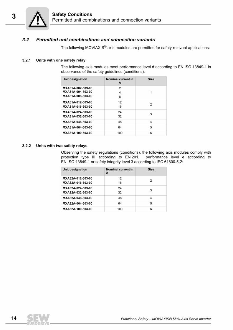
14
3 ermitted unit combinations and connection variantsafety Conditions
3.2 Permitted unit combinations and connection variantsThe following MOVIAXIS® axis modules are permitted for safety-relevant applications:
3.2.1 Units with one safety relayThe following axis modules meet performance level d according to EN ISO 13849-1 inobservance of the safety guidelines (conditions):
3.2.2 Units with two safety relaysObserving the safety regulations (conditions), the following axis modules comply withprotection type III according to EN 201, performance level e according toEN ISO 13849-1 or safety integrity level 3 according to IEC 61800-5-2:
Unit designation Nominal current in A
Size
MXA81A-002-503-00 MXA81A-004-503-00MXA81A-008-503-00
248
1
MXA81A-012-503-00MXA81A-016-503-00
1216
2
MXA81A-024-503-00MXA81A-032-503-00
2432
3
MXA81A-048-503-00 48 4
MXA81A-064-503-00 64 5
MXA81A-100-503-00 100 6
Unit designation Nominal current in A
Size
MXA82A-012-503-00MXA82A-016-503-00
1216
2
MXA82A-024-503-00MXA82A-032-503-00
2432
3
MXA82A-048-503-00 48 4
MXA82A-064-503-00 64 5
MXA82A-100-503-00 100 6
PS
Functional Safety – MOVIAXIS® Multi-Axis Servo Inverter
3Permitted unit combinations and connection variantsSafety Conditions
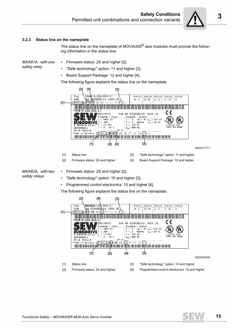
3.2.3 Status line on the nameplate
The status line on the nameplate of MOVIAXIS® axis modules must provide the follow-ing information in the status line:
MXA81A.. with one safety relay
• Firmware status: 2X and higher [2],
• "Safe technology" option: 11 and higher [3],
• Board Support Package: 12 and higher [4],
The following figure explains the status line on the nameplate.
MXA82A.. with two safety relays
• Firmware status: 2X and higher [2],
• "Safe technology" option: 10 and higher [3],
• Programmed control electronics: 10 and higher [4].
The following figure explains the status line on the nameplate.
4093317771
[1] Status line [3] "Safe technology" option: 11 and higher
[2] Firmware status: 2X and higher [4] Board Support Package: 12 and higher,
[1]
[1]
[2] [3]
[2] [3]
21
21
[4]
12
12
[4]
4093320459
[1] Status line [3] "Safe technology" option: 10 and higher
[2] Firmware status: 2X and higher, [4] Programmed control electronics: 10 and higher
[1]
[1]
[2] [3]
[2] [3]
21
21
[4]
MXA82A
12
[4]
12
Functional Safety – MOVIAXIS® Multi-Axis Servo Inverter
15
16
3 equirements on the installationafety Conditions
3.3 Requirements on the installation• Safety-related control cables are all cables between safety controller (or safety-
related disconnecting devices) and MOVIAXIS® terminals X7/X8.
• Power lines and safety-related control lines have to be installed in separate cables.
• The line length between the safety controller and MOVIAXIS® may not exceed 25 m.
Wiring technology must comply with EN 60204-1.
• The safety-related control lines must be routed according to EMC guidelines and asfollows:
– Outside an electrical installation space, shielded cables must be routed perma-nently (fixed) and protected against external damage, or other equivalent mea-sures have to be taken.
– Individual conductors can be routed inside an electrical installation space.
Adhere to the regulations in force for the application.
• Make sure that parasitic voltages cannot be generated in the safety-related controllines.
• Observe the values specified for safety components when designing the safetycircuits.
• Observe the notes in the MOVIAXIS® operating instructions on EMC compliantcabling.
• Use only voltage sources with safe disconnection (SELF/PELV) in accordance withVDE 0100. In case of a single fault, the voltage between the outputs or between anyoutput and grounded parts must not exceed DC 60 V.
• Observe the technical data of MOVIAXIS®.
• All connections (such as lines or data communication using bus systems) mustalready have been taken into account in the performance level of one of the sub-systems involved, or it must be possible that faults in the connections can be ex-cluded or neglected.
The fault assumption "short circuit between any two conductors" can be excludedaccording to EN ISO 13849-2 under the following conditions:
The conductors are
– permanently (fixed) installed and protected against external damage (for exampleusing a cable duct or armored conduit)
– installed in different light plastic-sheathed cables in an electrical installation spaceprovided that both the lines and the installation space meet the relevant require-ments, see EN 60204-1
– protected individually by a ground connection
3.3.1 Freewheeling diodeThe freewheeing diode [1] is needed when the safety relay(s) is/are controlled via thesafe outputs of the safety controller that are not able to switch the amounts of energy ofthe MOVIAXIS® safety relay.
The freewheeling diode [1] is also needed for group disconnection of more than eightaxis modules.
The freewheeling diode protects the outputs of the safety-related disconnection. Notethat the switch-off time increases, see also chapter Technical Data (page 40).
RS
Functional Safety – MOVIAXIS® Multi-Axis Servo Inverter
3Requirements on the installationSafety Conditions
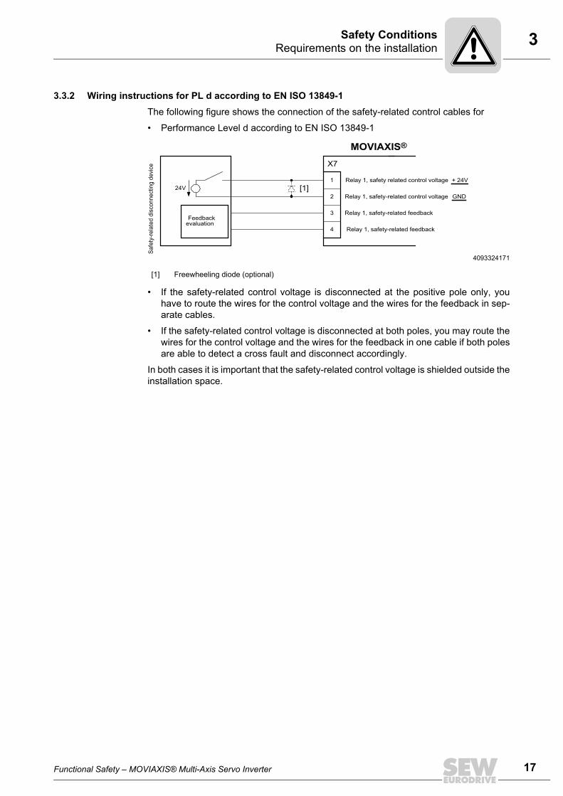
3.3.2 Wiring instructions for PL d according to EN ISO 13849-1The following figure shows the connection of the safety-related control cables for
• Performance Level d according to EN ISO 13849-1
• If the safety-related control voltage is disconnected at the positive pole only, youhave to route the wires for the control voltage and the wires for the feedback in sep-arate cables.
• If the safety-related control voltage is disconnected at both poles, you may route thewires for the control voltage and the wires for the feedback in one cable if both polesare able to detect a cross fault and disconnect accordingly.
In both cases it is important that the safety-related control voltage is shielded outside theinstallation space.
4093324171
[1] Freewheeling diode (optional)
1
2
3
4
X7
MOVIAXIS®
Relay 1, safety related control voltage + 24V
Relay 1, safety-related feedback
Relay 1, safety-related feedback
Relay 1, safety-related control voltage GND
Safe
ty-re
late
d di
scon
nect
ing
devi
ce
24V
Feedbackevaluation
[1]
Functional Safety – MOVIAXIS® Multi-Axis Servo Inverter
17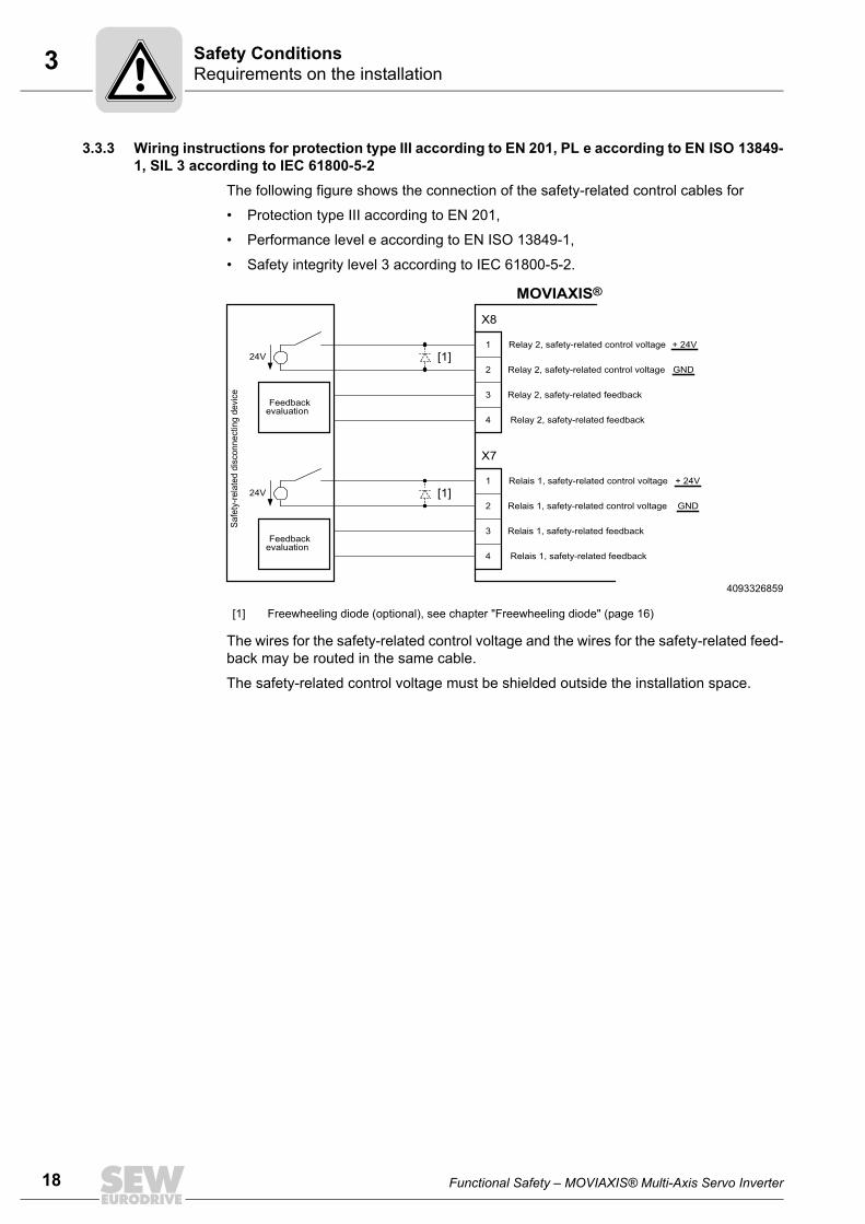
18
3 equirements on the installationafety Conditions
3.3.3 Wiring instructions for protection type III according to EN 201, PL e according to EN ISO 13849-1, SIL 3 according to IEC 61800-5-2
The following figure shows the connection of the safety-related control cables for
• Protection type III according to EN 201,
• Performance level e according to EN ISO 13849-1,
• Safety integrity level 3 according to IEC 61800-5-2.
The wires for the safety-related control voltage and the wires for the safety-related feed-back may be routed in the same cable.
The safety-related control voltage must be shielded outside the installation space.
4093326859
[1] Freewheeling diode (optional), see chapter "Freewheeling diode" (page 16)
1
2
3
4
X7
MOVIAXIS®
Relais 1, safety-related control voltage + 24V
Relais 1, safety-related feedback
Relais 1, safety-related feedback
Relais 1, safety-related control voltage GND
Safe
ty-re
late
d di
scon
nect
ing
devi
ce
24V
Feedbackevaluation
1
2
3
4
X8
Relay 2, safety-related control voltage + 24V
Relay 2, safety-related feedback
Relay 2, safety-related feedback
Relay 2, safety-related control voltage GND24V
Feedbackevaluation
[1]
[1]
RS
Functional Safety – MOVIAXIS® Multi-Axis Servo Inverter

3Requirements on external safety controllers/safety relaysSafety Conditions
3.4 Requirements on external safety controllers/safety relaysA safety relay can be used as an alternative to a safety controller. The following require-ments apply analogously.
• To meet the requirements for a certain safety level, at least one approval must beavailable for the controller according to the following table. The disconnection of thesafety-related control voltage must be designed for the same safety level.
• The feedback on the switching condition of the relays for fault detection must be eval-uated according to the requirements.
• The wiring of the safety controller must be suitable for the required safety class, seemanufacturer documentation.
• If the DC 24 V supply is safely disconnected at the positive pole only, no testsignals must be applied to this pole in disconnected condition.
• If the DC 24 V supply is disconnected at both poles, the test pulses must not beapplied at the same time at the plus and minus outputs. In this case, the test pulsemust be applied with a time delay.
• SEW-EURODRIVE recommends to switch off the 24 V supply at two poles.
• You must observe the values specified for the controller when you design the circuit.
• The switching capacity of the control must correspond at least to the maximumpermitted limited output current of the DC 24 V voltage supply. Observe the control-ler manufacturer's instructions concerning the permitted contact rating andrequired fusing for emergency stop relays. If the manufacturer provides nospecific information, the contacts must be protected with 0.6 times the nominalvalue of the maximum contact rating specified by the manufacturer.
• To ensure protection against unintended restart according to EN 1037, the safetycontrollers must be designed and connected in such a way that resetting the controldevice alone does not lead to a restart. A restart may only be carried out after anadditional reset of the controller.
• If a fault cannot be acknowledged, you have to de-energize the device.
• The wiring of the safety controller must be suitable for the required safety class, seemanufacturer documentation.
Application Demands on the controller
PL d according to EN ISO 13849-1 • PL d according to EN ISO 13849-1 or• SIL 2 according to EN 61800-5-2
PL e according to EN ISO 13849-1 • PL e according to EN ISO 13849-1 or • SIL 3 according to IEC 61800-5-2
SIL 3 according to IEC 61800-5-2 • PL e according to EN ISO 13849-1 or • SIL 3 according to IEC 61800-5-2
Protection type III according to EN 201
• Protection type III according to EN 201
Functional Safety – MOVIAXIS® Multi-Axis Servo Inverter
19
20
3 equirements on startupafety Conditions
3.5 Requirements on startup• You must document startup and verify the safety functions. Observe the limitations
for the safety functions of MOVIAXIS® in chapter "Limitations" (page 12) for the ver-ification of the safety functions. Non-safety-relevant parts and components that affectthe result of the verification test (e.g. motor brake) must be deactivated, if necessary.
• For using MOVIAXIS® in safety-related applications, it is essential that you performand record startup checks for the disconnecting device and correct wiring.
• During the startup procedure/function test, perform a measurement in order to checkthe correct assignment of the respective voltage supply (X7,X8).
• The function test must be carried out in succession for all potentials, i.e. separately.
3.6 Requirements on operation• Operation is only allowed within the limits specified in the data sheets. This principle
applies to the external safety controller as well as MOVIAXIS®.
• You must check the safety functions on a regular basis to ensure proper functioning.The test intervals should be specified in accordance with the risk assessment.
RS
Functional Safety – MOVIAXIS® Multi-Axis Servo Inverter
4General informationConnection Variants
4 Connection Variants4.1 General information
Generally, all the connection variants listed in this documentation are permitted forsafety-relevant applications as long as the basic safety concept is met. This means youhave to make sure that the DC 24 V safety inputs are operated by an external safetyrelay or a safety controller, thus preventing automatic restart.
All safety-relevant conditions mentioned in chapters 2, 3 and 4 of the documentation inhand must be met for the basic selection, installation, and application of the safety com-ponents, such as safety relay, emergency off switch, etc., and the approved connectionvariants.
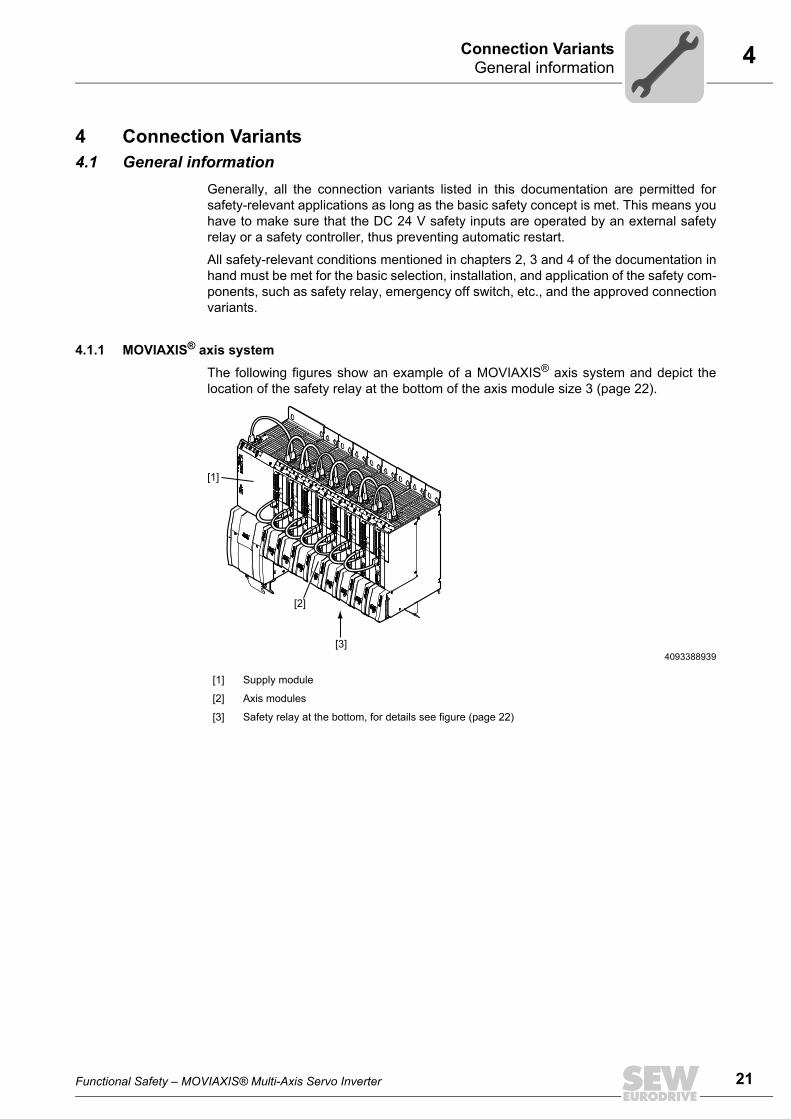
4.1.1 MOVIAXIS® axis systemThe following figures show an example of a MOVIAXIS® axis system and depict thelocation of the safety relay at the bottom of the axis module size 3 (page 22).
4093388939
[1] Supply module
[2] Axis modules
[3] Safety relay at the bottom, for details see figure (page 22)
[2]
[1]
[3]
Functional Safety – MOVIAXIS® Multi-Axis Servo Inverter
21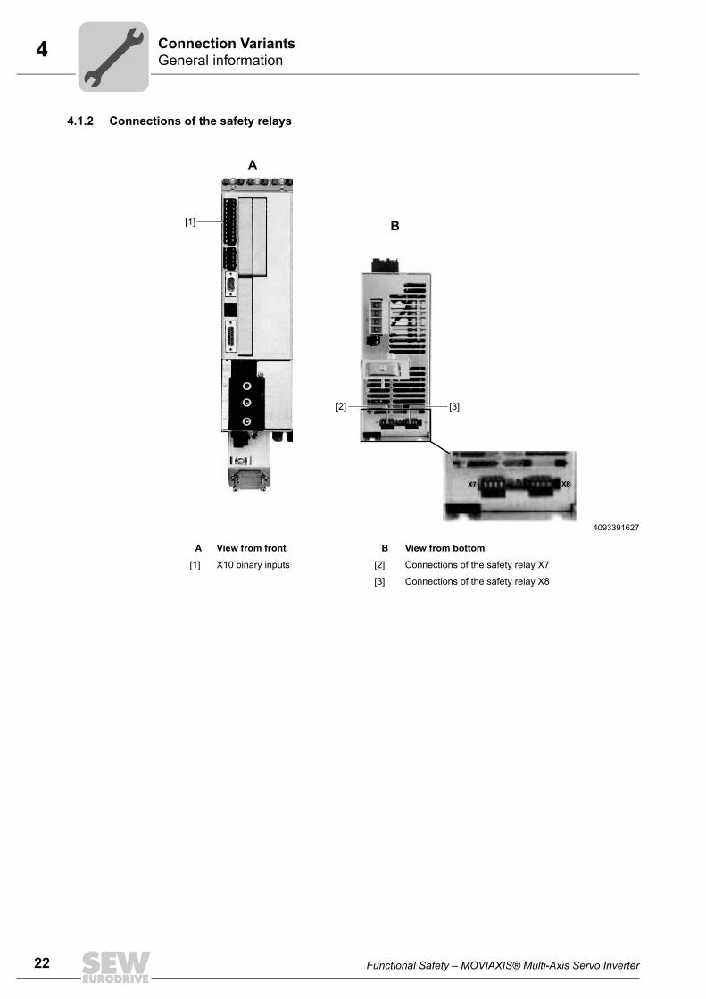
22
4 eneral informationonnection Variants
4.1.2 Connections of the safety relays
4093391627
A View from front B View from bottom
[1] X10 binary inputs [2] Connections of the safety relay X7
[3] Connections of the safety relay X8
[2] [3]
[1]
A
B
X7 X8
GC
Functional Safety – MOVIAXIS® Multi-Axis Servo Inverter
4RequirementsConnection Variants
4.2 Requirements4.2.1 Using safety relays
The requirements of the manufacturers of safety relays (such as protecting the outputcontacts against welding) or other safety components must be strictly observed. For thecable routing, observe the basic requirements listed in chapters 2, 3 and 4 of thedocumentation in hand.
For connecting MOVIAXIS® with the safety relays, observe the installation requirementsin the chapter "Requirements on the installation" (page 16) in this document.
Other instructions by the manufacturer on the use of safety relays for specific applica-tions must also be observed.
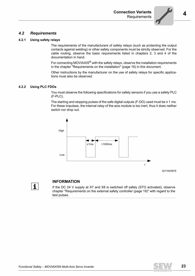
4.2.2 Using PLC FDOsYou must observe the following specifications for safety sensors if you use a safety PLC(F-PLC).
The starting and stopping pulses of the safe digital outputs (F-DO) used must be ≤ 1 ms.For these impulses, the internal relay of the axis module is too inert, thus it does neitherswitch nor drop out.
3211043979
<1ms >1000ms
High
Low
t
INFORMATIONIf the DC 24 V supply at X7 and X8 is switched off safely (STO activated), observechapter "Requirements on the external safety controller (page 19)" with regard to thetest pulses.
Functional Safety – MOVIAXIS® Multi-Axis Servo Inverter
23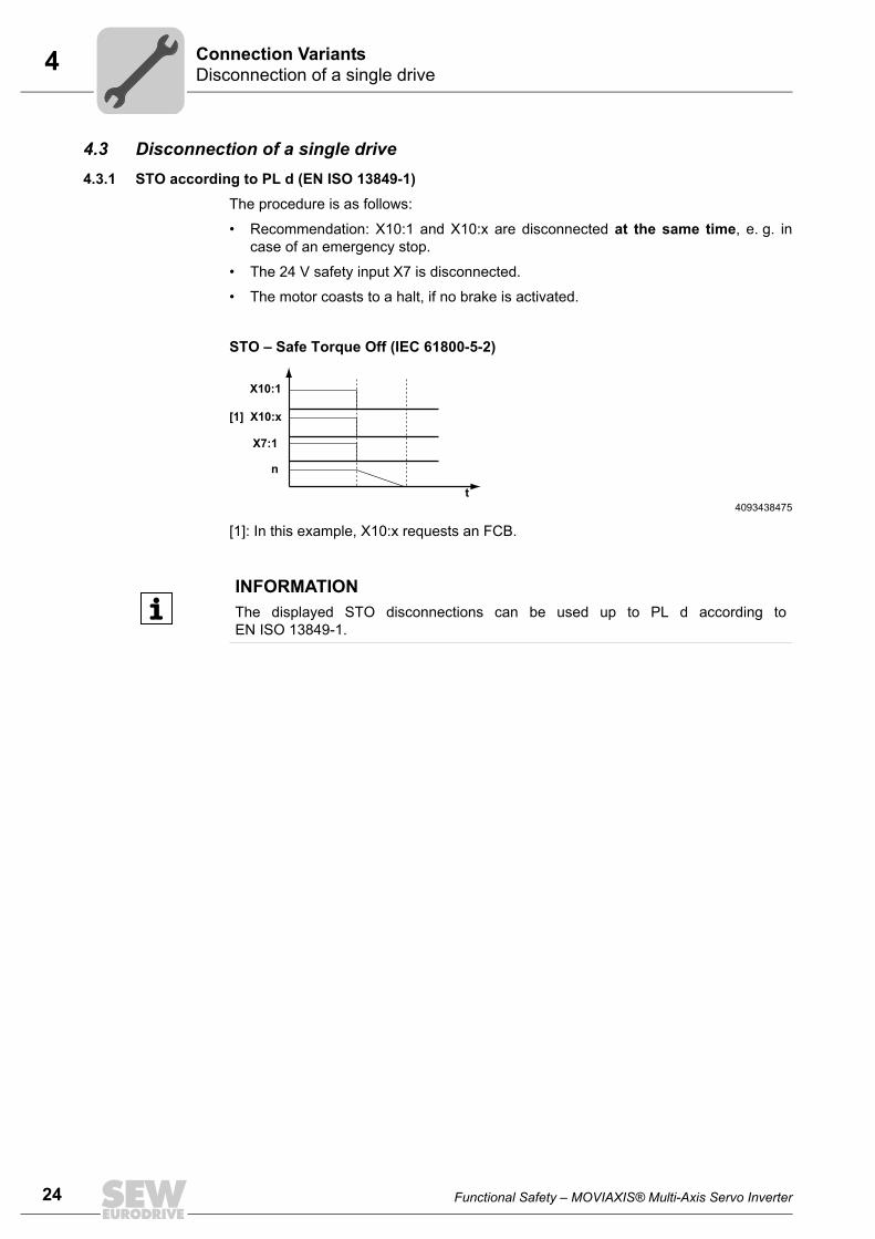
24
4 isconnection of a single driveonnection Variants
4.3 Disconnection of a single drive4.3.1 STO according to PL d (EN ISO 13849-1)
The procedure is as follows:
• Recommendation: X10:1 and X10:x are disconnected at the same time, e. g. incase of an emergency stop.
• The 24 V safety input X7 is disconnected.
• The motor coasts to a halt, if no brake is activated.
STO – Safe Torque Off (IEC 61800-5-2)
[1]: In this example, X10:x requests an FCB.
4093438475t
n
X7:1
[1] X10:x
X10:1
INFORMATIONThe displayed STO disconnections can be used up to PL d according toEN ISO 13849-1.
DC
Functional Safety – MOVIAXIS® Multi-Axis Servo Inverter
4Disconnection of a single driveConnection Variants
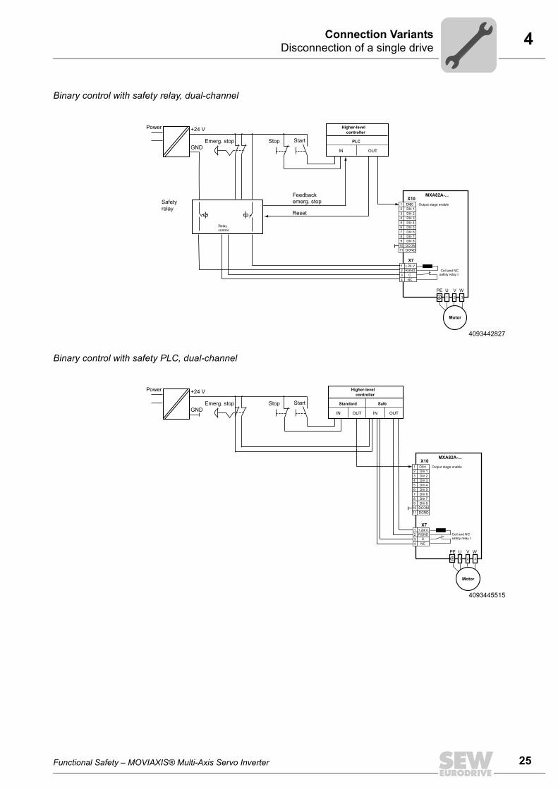
Binary control with safety relay, dual-channel
Binary control with safety PLC, dual-channel
4093442827
+24 V
Feedbackemerg. stop
Reset
Higher-levelcontroller
PLC
IN OUT
Safetyrelay
Emerg. stop StartStopGND
Power
Relaycontrol
MXA82A-...
2
X101 DI000
DI0 13 DI0 24 DI0 35 DI0 46 DI0 57 DI0 68 DI0 79 DI0 810 DCOM11 DGND
X7+ 24 VRGND Coil and NC
safety relay I
1 2 3
PE U V W
1234
CNC
Output stage enable
Motor
4093445515
+24 V Higher-levelcontroller
Standard Safe
IN OUT
Emerg. stop StartStopGND
Power
IN OUT
MXA82A-...
2
X101 DI00
DI0 13 DI0 24 DI0 35 DI0 46 DI0 57 DI0 68 DI0 79 DI0 810 DCOM11 DGND
X7
Coil and NCsafety relay I
1 2 3
PE U V W
+ 24 VRGND
1234
CNC
Output stage enable
Motor
Functional Safety – MOVIAXIS® Multi-Axis Servo Inverter
25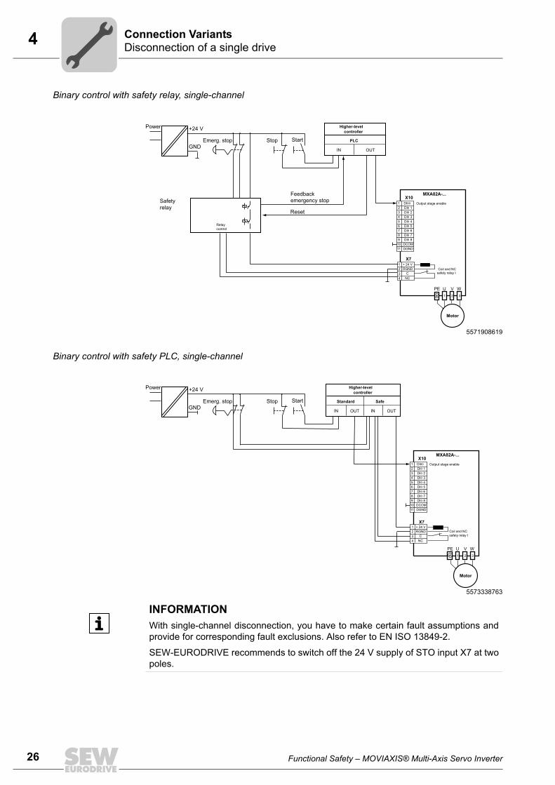
26
4 isconnection of a single driveonnection Variants
Binary control with safety relay, single-channel
Binary control with safety PLC, single-channel
5571908619
+24 V
Feedbackemergency stop
Reset
Higher-levelcontroller
PLC
IN OUT
Safetyrelay
Emerg. stop StartStopGND
Power
Relaycontrol
MXA82A-...
2
X101 DI00
DI0 13 DI0 24 DI0 35 DI0 46 DI0 57 DI0 68 DI0 79 DI0 810 DCOM11 DGND
X7+ 24 VRGND Coil and NC
safety relay I
1 2 3
PE U V W
1234
CNC
Output stage enable
Motor
5573338763
+24 V Higher-levelcontroller
Standard Safe
IN OUT
Emerg. stop StartStopGND
Power
IN OUT
MXA82A-...
2
X101 DI00
DI0 13 DI0 24 DI0 35 DI0 46 DI0 57 DI0 68 DI0 79 DI0 810 DCOM11 DGND
X7
Coil and NCsafety relay I
1 2 3
PE U V W
+ 24 VRGND
1234
CNC
Output stage enable
Motor
INFORMATIONWith single-channel disconnection, you have to make certain fault assumptions andprovide for corresponding fault exclusions. Also refer to EN ISO 13849-2.
SEW-EURODRIVE recommends to switch off the 24 V supply of STO input X7 at twopoles.
DC
Functional Safety – MOVIAXIS® Multi-Axis Servo Inverter
4Disconnection of a single driveConnection Variants
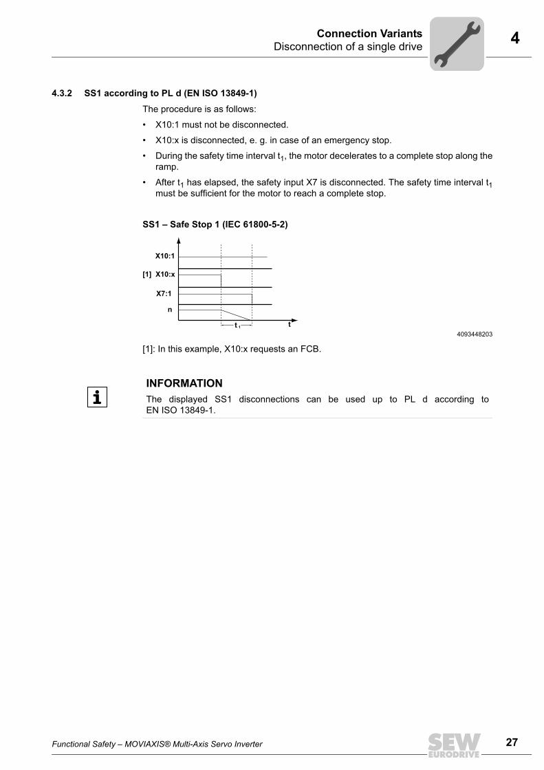
4.3.2 SS1 according to PL d (EN ISO 13849-1)
The procedure is as follows:
• X10:1 must not be disconnected.
• X10:x is disconnected, e. g. in case of an emergency stop.
• During the safety time interval t1, the motor decelerates to a complete stop along theramp.
• After t1 has elapsed, the safety input X7 is disconnected. The safety time interval t1must be sufficient for the motor to reach a complete stop.
SS1 – Safe Stop 1 (IEC 61800-5-2)
[1]: In this example, X10:x requests an FCB.
4093448203t
n
X7:1
[1] X10:x
t 1
X10:1
INFORMATIONThe displayed SS1 disconnections can be used up to PL d according toEN ISO 13849-1.
Functional Safety – MOVIAXIS® Multi-Axis Servo Inverter
27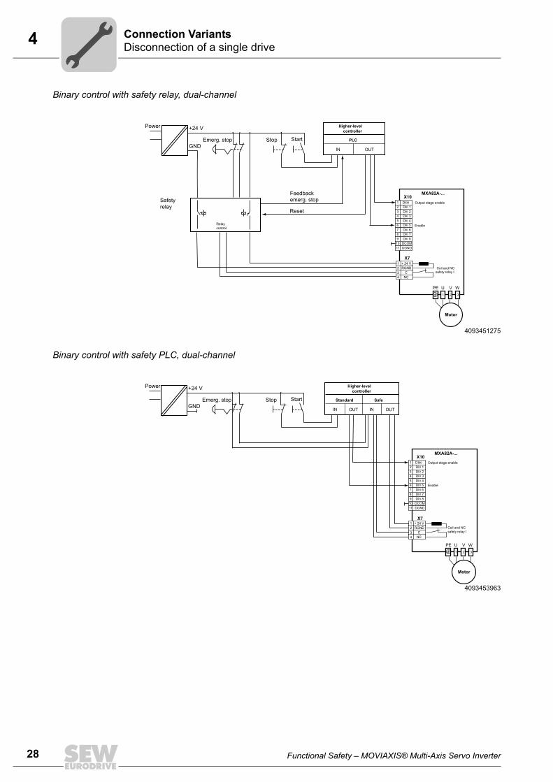
28
4 isconnection of a single driveonnection Variants
Binary control with safety relay, dual-channel
Binary control with safety PLC, dual-channel
4093451275
+24 V
Feedbackemerg. stop
Reset
Higher-levelcontroller
PLC
IN OUT
Safetyrelay
Emerg. stop StartStopGND
Power
Relaycontrol
MXA82A-...
2
X101 DI00
DI0 13 DI0 24 DI0 35 DI0 46 DI0 57 DI0 68 DI0 79 DI0 810 DCOM11 DGND
X7+ 24 VRGND Coil and NC
safety relay I
1 2 3
PE U V W
1234
CNC
Output stage enable
Motor
Enable
4093453963
+24 V Higher-levelcontroller
Standard Safe
IN OUT
Emerg. stop StartStopGND
Power
IN OUT
MXA82A-...
2
X101 DI00
DI0 13 DI0 24 DI0 35 DI0 46 DI0 57 DI0 68 DI0 79 DI0 810 DCOM11 DGND
X7
Coil and NCsafety relay I
1 2 3
PE U V W
+ 24 VRGND
1234
CNC
Output stage enable
Enable
Motor
DC
Functional Safety – MOVIAXIS® Multi-Axis Servo Inverter
4Disconnection of a single driveConnection Variants
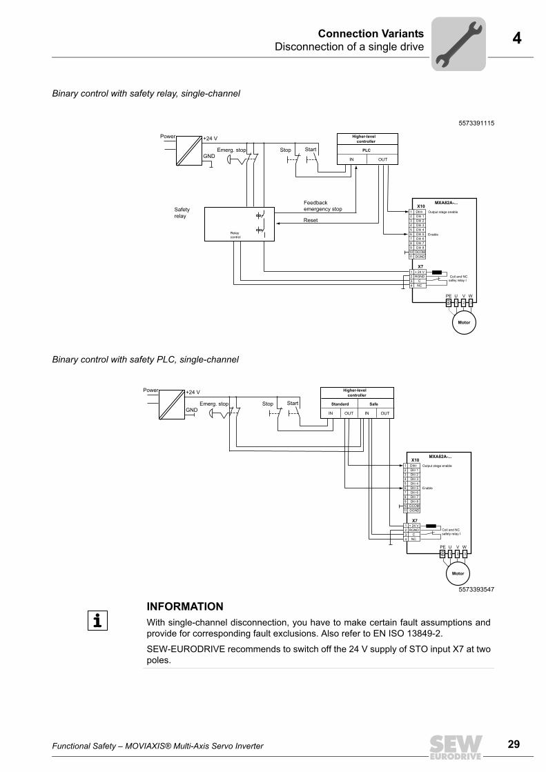
Binary control with safety relay, single-channel
Binary control with safety PLC, single-channel
5573391115
+24 V
Feedbackemergency stop
Reset
Higher-levelcontroller
PLC
IN OUT
Safetyrelay
Emerg. stop StartStopGND
Power
Relaycontrol
MXA82A-...
2
X101 DI00
DI0 13 DI0 24 DI0 35 DI0 46 DI0 57 DI0 68 DI0 79 DI0 810 DCOM11 DGND
X7+ 24 VRGND Coil and NC
safey relay I
1 2 3
PE U V W
1234
CNC
Output stage enable
Motor
Enable
5573393547
+24 V Higher-levelcontroller
Standard Safe
IN OUT
Emerg. stop StartStopGND
Power
IN OUT
MXA82A-...
2
X101 DI00
DI0 13 DI0 24 DI0 35 DI0 46 DI0 57 DI0 68 DI0 79 DI0 810 DCOM11 DGND
X7
Coil and NCsafety relay I
1 2 3
PE U V W
+ 24 VRGND
1234
CNC
Output stage enable
Enable
Motor
INFORMATIONWith single-channel disconnection, you have to make certain fault assumptions andprovide for corresponding fault exclusions. Also refer to EN ISO 13849-2.
SEW-EURODRIVE recommends to switch off the 24 V supply of STO input X7 at twopoles.
Functional Safety – MOVIAXIS® Multi-Axis Servo Inverter
29
30
4 isconnection of a single driveonnection Variants
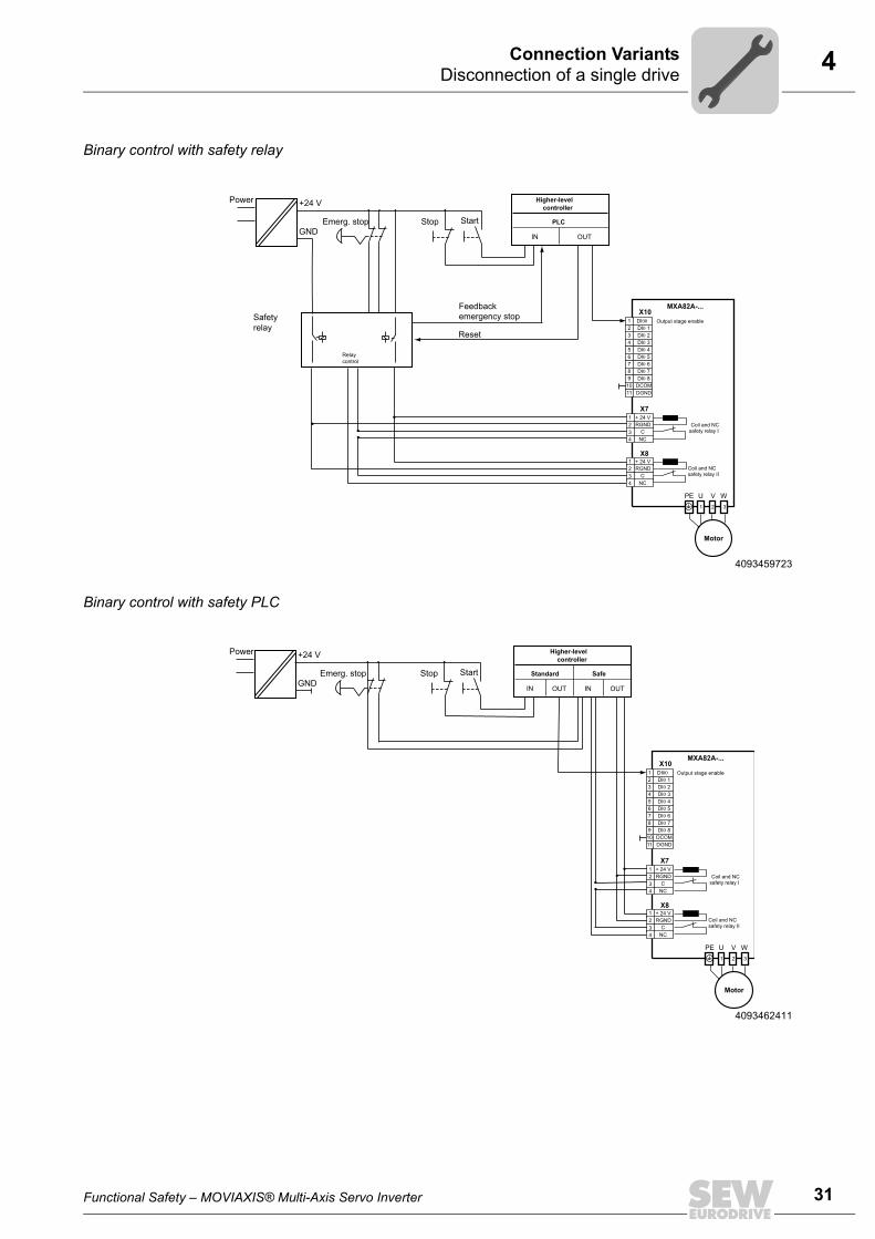
4.3.3 STO according to PL e (EN ISO 13849-1)
The procedure is as follows:
• Recommendation: X10:1 and X10:x are disconnected at the same time, e. g. incase of an emergency stop.
• The 24 V safety inputs X7 and X8 are disconnected.
• The motor coasts to a halt, if no brake is activated.
STO – Safe Torque Off (IEC 61800-5-2)
[1]: In this example, X10:x requests an FCB.
4093456651t
n
X8:1
X7:1
[1] X10:x
X10:1
INFORMATIONThe depicted STO disconnections can be used up to PL e according to EN ISO 13849-1, protection type III according to EN 201, or SIL3 according to IEC 61800-5-2.
DC
Functional Safety – MOVIAXIS® Multi-Axis Servo Inverter
4Disconnection of a single driveConnection Variants
Binary control with safety relay
Binary control with safety PLC
4093459723
+24 V
Feedbackemergency stop
Reset
Higher-levelcontroller
PLC
IN OUT
Safetyrelay
Emerg. stop StartStopGND
Power
Relaycontrol
MXA82A-...
2
X101 DI00
DI0 13 DI0 24 DI0 35 DI0 46 DI0 57 DI0 68 DI0 79 DI0 810 DCOM11 DGND
X7
X8
+ 24 VRGND Coil and NC
safety relay I
Coil and NCsafety relay II
1 2 3
PE U V W
1234
CNC
+ 24 VRGND
1234
CNC
Output stage enable
Motor
4093462411
+24 V Higher-levelcontroller
Standard Safe
IN OUT
Emerg. stop StartStopGND
Power
IN OUT
MXA82A-...
2
X101 DI00
DI0 13 DI0 24 DI0 35 DI0 46 DI0 57 DI0 68 DI0 79 DI0 810 DCOM11 DGND
X7
X8
+ 24 VRGND Coil and NC
safety relay I
Coil and NCsafety relay II
1 2 3
PE U V W
1234
CNC
+ 24 VRGND
1234
CNC
Output stage enable
Motor
Functional Safety – MOVIAXIS® Multi-Axis Servo Inverter
31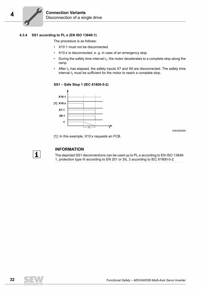
32
4 isconnection of a single driveonnection Variants
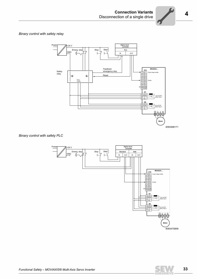
4.3.4 SS1 according to PL e (EN ISO 13849-1)
The procedure is as follows:
• X10:1 must not be disconnected.
• X10:x is disconnected, e. g. in case of an emergency stop.
• During the safety time interval t1, the motor decelerates to a complete stop along theramp.
• After t1 has elapsed, the safety inputs X7 and X8 are disconnected. The safety timeinterval t1 must be sufficient for the motor to reach a complete stop.
SS1 – Safe Stop 1 (IEC 61800-5-2)
[1]: In this example, X10:x requests an FCB.
4093465099t
n
X8:1
X7:1
[1] X10:x
t 1
X10:1
INFORMATIONThe depicted SS1 disconnections can be used up to PL e according to EN ISO 13849-1, protection type III according to EN 201 or SIL 3 according to IEC 61800-5-2.
DC
Functional Safety – MOVIAXIS® Multi-Axis Servo Inverter
4Disconnection of a single driveConnection Variants
Binary control with safety relay
Binary control with safety PLC
4093468171
+24 V
Feedbackemergency stop
Reset
Higher-levelcontroller
PLC
IN OUT
Safetyrelay
Emerg. stop StartStopGND
Power
Relaycontrol
MXA82A-...
2
X101 DI00
DI0 13 DI0 24 DI0 35 DI0 46 DI0 57 DI0 68 DI0 79 DI0 810 DCOM11 DGND
X7
X8
+ 24 VRGND Coil and NC
safety relay I
Coil and NCsafety relay II
1 2 3
PE U V W
1234
CNC
+ 24 VRGND
1234
CNC
Output stage enable
Enable
Motor
4093470859
+24 V Higher-levelcontroller
Standard Safe
IN OUT
Emerg. stop StartStopGND
Power
IN OUT
MXA82A-...
2
X101 DI00
DI0 13 DI0 24 DI0 35 DI0 46 DI0 57 DI0 68 DI0 79 DI0 810 DCOM11 DGND
X7
X8
+ 24 VRGND Coil and NC
safety relay I
Coil and NCsafety relay II
1 2 3
PE U V W
1234
CNC
+ 24 VRGND
1234
CNC
Output stage enable
Enable
Motor
Functional Safety – MOVIAXIS® Multi-Axis Servo Inverter
33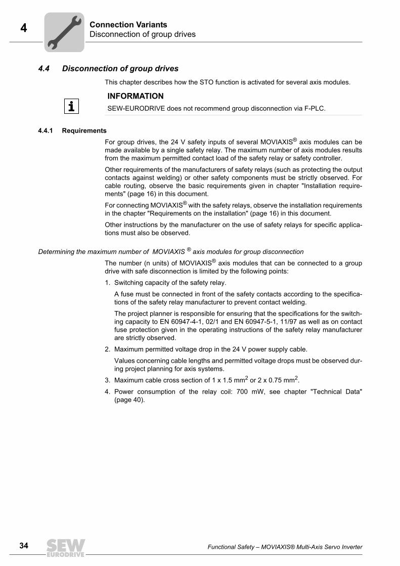
34
4 isconnection of group drivesonnection Variants
4.4 Disconnection of group drivesThis chapter describes how the STO function is activated for several axis modules.
4.4.1 RequirementsFor group drives, the 24 V safety inputs of several MOVIAXIS® axis modules can bemade available by a single safety relay. The maximum number of axis modules resultsfrom the maximum permitted contact load of the safety relay or safety controller.
Other requirements of the manufacturers of safety relays (such as protecting the outputcontacts against welding) or other safety components must be strictly observed. Forcable routing, observe the basic requirements given in chapter "Installation require-ments" (page 16) in this document.
For connecting MOVIAXIS® with the safety relays, observe the installation requirementsin the chapter "Requirements on the installation" (page 16) in this document.
Other instructions by the manufacturer on the use of safety relays for specific applica-tions must also be observed.
Determining the maximum number of MOVIAXIS ® axis modules for group disconnection
The number (n units) of MOVIAXIS® axis modules that can be connected to a groupdrive with safe disconnection is limited by the following points:
1. Switching capacity of the safety relay.
A fuse must be connected in front of the safety contacts according to the specifica-tions of the safety relay manufacturer to prevent contact welding.
The project planner is responsible for ensuring that the specifications for the switch-ing capacity to EN 60947-4-1, 02/1 and EN 60947-5-1, 11/97 as well as on contactfuse protection given in the operating instructions of the safety relay manufacturerare strictly observed.
2. Maximum permitted voltage drop in the 24 V power supply cable.
Values concerning cable lengths and permitted voltage drops must be observed dur-ing project planning for axis systems.
3. Maximum cable cross section of 1 x 1.5 mm2 or 2 x 0.75 mm2.
4. Power consumption of the relay coil: 700 mW, see chapter "Technical Data"(page 40).
INFORMATIONSEW-EURODRIVE does not recommend group disconnection via F-PLC.
DC
Functional Safety – MOVIAXIS® Multi-Axis Servo Inverter
4Disconnection of group drivesConnection Variants
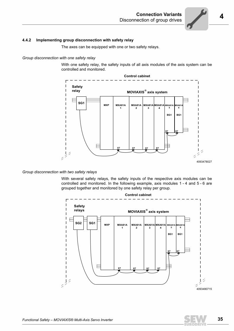
4.4.2 Implementing group disconnection with safety relay
The axes can be equipped with one or two safety relays.
Group disconnection with one safety relay
With one safety relay, the safety inputs of all axis modules of the axis system can becontrolled and monitored.
Group disconnection with two safety relays
With several safety relays, the safety inputs of the respective axis modules can becontrolled and monitored. In the following example, axis modules 1 - 4 and 5 - 6 aregrouped together and monitored by one safety relay per group.
4093478027
MXP MXA81A1
MXA81A2
MXA81A3
MXA81A4
MXA81A5
MXA81A6
Safetyrelay MOVIAXIS axis system®
Control cabinet
X7 X7 X7 X7
X7 X7
BG1BG1
SG1
4093480715
MXP MXA81A1
MXA81A2
MXA81A3
MXA81A4
MXA81A5
MXA81A6
Safetyrelays MOVIAXIS axis system®
Control cabinet
X7 X7 X7 X7
X7 X7
BG1
SG2 SG1
BG1
Functional Safety – MOVIAXIS® Multi-Axis Servo Inverter
35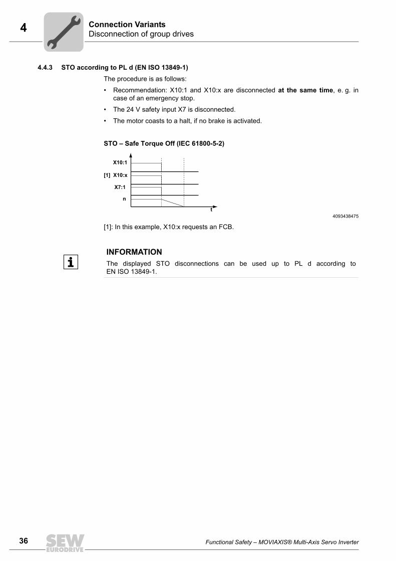
36
4 isconnection of group drivesonnection Variants
4.4.3 STO according to PL d (EN ISO 13849-1)The procedure is as follows:
• Recommendation: X10:1 and X10:x are disconnected at the same time, e. g. incase of an emergency stop.
• The 24 V safety input X7 is disconnected.
• The motor coasts to a halt, if no brake is activated.
STO – Safe Torque Off (IEC 61800-5-2)
[1]: In this example, X10:x requests an FCB.
4093438475t
n
X7:1
[1] X10:x
X10:1
INFORMATIONThe displayed STO disconnections can be used up to PL d according toEN ISO 13849-1.
DC
Functional Safety – MOVIAXIS® Multi-Axis Servo Inverter
4Disconnection of group drivesConnection Variants
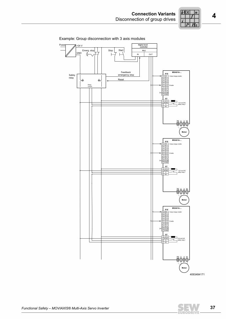
Example: Group disconnection with 3 axis modules
4093484171
MXA81A-...
2
X101 DI00
DI0 13 DI0 24 DI0 35 DI0 46 DI0 57 DI0 68 DI0 79 DI0 810 DCOM11 DGND
X7+ 24 VRGND Coil and NC
safey relay I
1 2 3
PE U V W
1234
CNC
Output stage enable
Enable
+24 V
Feedbackemergency stop
Reset
Higher-levelcontroller
PLC
IN OUT
Safetyrelay
Emerg. stop StartStopGND
Power
Motor
Relaycontrol
MXA81A-...
2
X101 DI00
DI0 13 DI0 24 DI0 35 DI0 46 DI0 57 DI0 68 DI0 79 DI0 810 DCOM11 DGND
X7+ 24 VRGND Coil and NC
safety relay I
1 2 3
PE U V W
1234
CNC
Output stage enable
Enable
Motor
MXA81A-...
2
X101 DI00
DI0 13 DI0 24 DI0 35 DI0 46 DI0 57 DI0 68 DI0 79 DI0 810 DCOM11 DGND
X7
Coil and NCsafety relay I
1 2 3
PE U V W
+ 24 VRGND
1234
CNC
Output stage enable
Enable
Motor
Functional Safety – MOVIAXIS® Multi-Axis Servo Inverter
Pi
fkVA
Hz
n
37
38
4 isconnection of group drivesonnection Variants
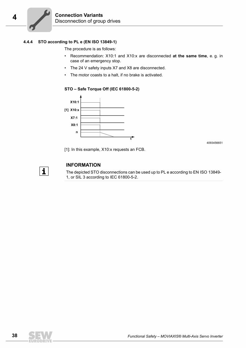
4.4.4 STO according to PL e (EN ISO 13849-1)The procedure is as follows:
• Recommendation: X10:1 and X10:x are disconnected at the same time, e. g. incase of an emergency stop.
• The 24 V safety inputs X7 and X8 are disconnected.
• The motor coasts to a halt, if no brake is activated.
STO – Safe Torque Off (IEC 61800-5-2)
[1]: In this example, X10:x requests an FCB.
4093456651t
n
X8:1
X7:1
[1] X10:x
X10:1
INFORMATIONThe depicted STO disconnections can be used up to PL e according to EN ISO 13849-1, or SIL 3 according to IEC 61800-5-2.
DC
Functional Safety – MOVIAXIS® Multi-Axis Servo Inverter
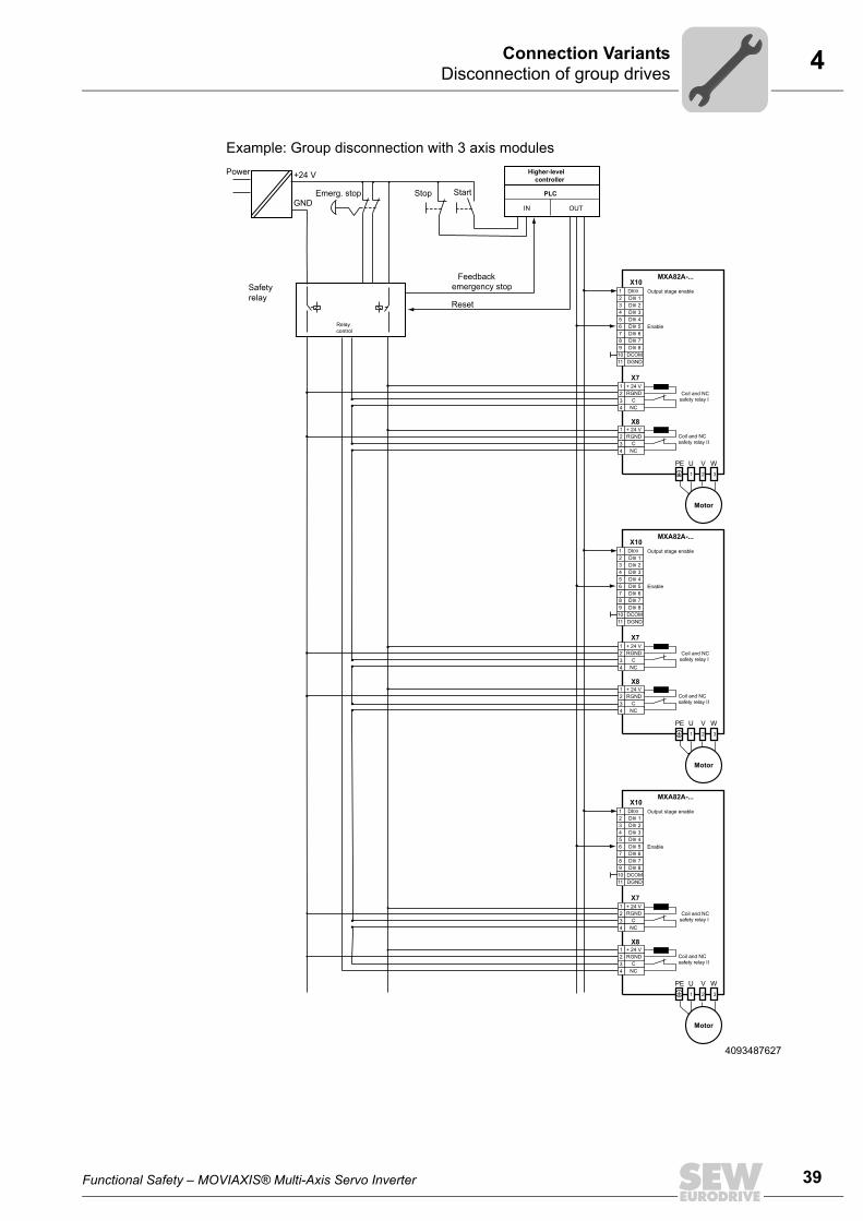
4Disconnection of group drivesConnection Variants
Example: Group disconnection with 3 axis modules
4093487627
MXA82A-...
2
X101 DI00
DI0 13 DI0 24 DI0 35 DI0 46 DI0 57 DI0 68 DI0 79 DI0 810 DCOM11 DGND
X7
X8
+ 24 VRGND Coil and NC
safety relay I
Coil and NCsafety relay II
1 2 3
PE U V W
1234
CNC
+ 24 VRGND
1234
CNC
Output stage enable
Enable
+24 V
Feedbackemergency stop
Reset
Higher-levelcontroller
PLC
IN OUT
Safetyrelay
Emerg. stop StartStopGND
Power
Motor
Relaycontrol
MXA82A-...
2
X101 DI00
DI0 13 DI0 24 DI0 35 DI0 46 DI0 57 DI0 68 DI0 79 DI0 810 DCOM11 DGND
X7
X8
+ 24 VRGND Coil and NC
safety relay I
Coil and NCsafety relay II
1 2 3
PE U V W
1234
CNC
+ 24 VRGND
1234
CNC
Output stage enable
Enable
Motor
MXA82A-...
2
X101 DI00
DI0 13 DI0 24 DI0 35 DI0 46 DI0 57 DI0 68 DI0 79 DI0 810 DCOM11 DGND
X7
X8
+ 24 VRGND Coil and NC
safety relay I
Coil and NCsafety relay II
1 2 3
PE U V W
1234
CNC
+ 24 VRGND
1234
CNC
Output stage enable
Enable
Motor
Functional Safety – MOVIAXIS® Multi-Axis Servo Inverter
39
40
5 echnical Data
5 Technical Data
The axis modules of the MOVIAXIS® servo inverter can be equipped with optional safetyfunctions. With these options, MOVIAXIS® can implement safe torque off. For size 1,you can use one safety relay as option. For sizes 2 - 6, you can use one or two safetyrelays to achieve different safety classes.
The safety relays (X7, X8) will be queried and evaluated separately when you use 2safety relays.
WARNINGNote:The manufacturer recommends a minimum load for the switching contacts so that thesafety relays function properly.
MOVIAXIS® with safety technology MXA81.. MXA82..
Equipped with 1 safety relay 2 safety relays
Necessary minimum load at the contacts of the safety relays (X7, X8)
DC 12 V / 10 mA
Type of relay Normally closed contact (at the signaling contacts X7, X8)
Control voltage V24V at the relay coilTerminal X7; 1, 2Terminal X8; 1, 2
DC +19.2 V to +30 V (> 15 mA) => relay coil energizedDC -2 V to +2 V (> 2 mA) => relay coil dropped out safely
Only use voltage sources with safe disconnection (SELV/PELV) in accordance with VDE 0100 for the control input at terminals 1 and 2.
Supply power of the relay coil Power consumption typically 700 mW (500 – 950 mW)
Energy of the relay coil Over the entire voltage range DC 30 V (19.2 V – 30 V), max. 6.5 mJ
Feedback contact (monitoring) Switching voltage DC 30 V (DC 19.2 – 30 V)Fusing provided by customer I = 3 A
Cable cross section at safety input 0.75 – 1.5 mm2 (AWG 18 – 16)
Time interval until feedback to external safety controller
Without freewheeling diode: max. 20 msWith free-wheeling diode 1N4148 parallel to relay max 140 ms at < 2 m connecting lead
Time interval until the output stage is switched off
Without freewheeling diode: max. 5 msWith free-wheeling diode 1N4148 parallel to relay max 115 ms at < 2 m connecting lead
Minimum break time until output stage is released again after the cur-rent supply has been provided to relay coil via X7, X8
100 ms
Minimum operating time of the safety relays 5 s
Minimum interrupting time of the safety relays 10 s
T
Pi
fkVA
Hz
n
Functional Safety – MOVIAXIS® Multi-Axis Servo Inverter
5Safety characteristicsTechnical Data
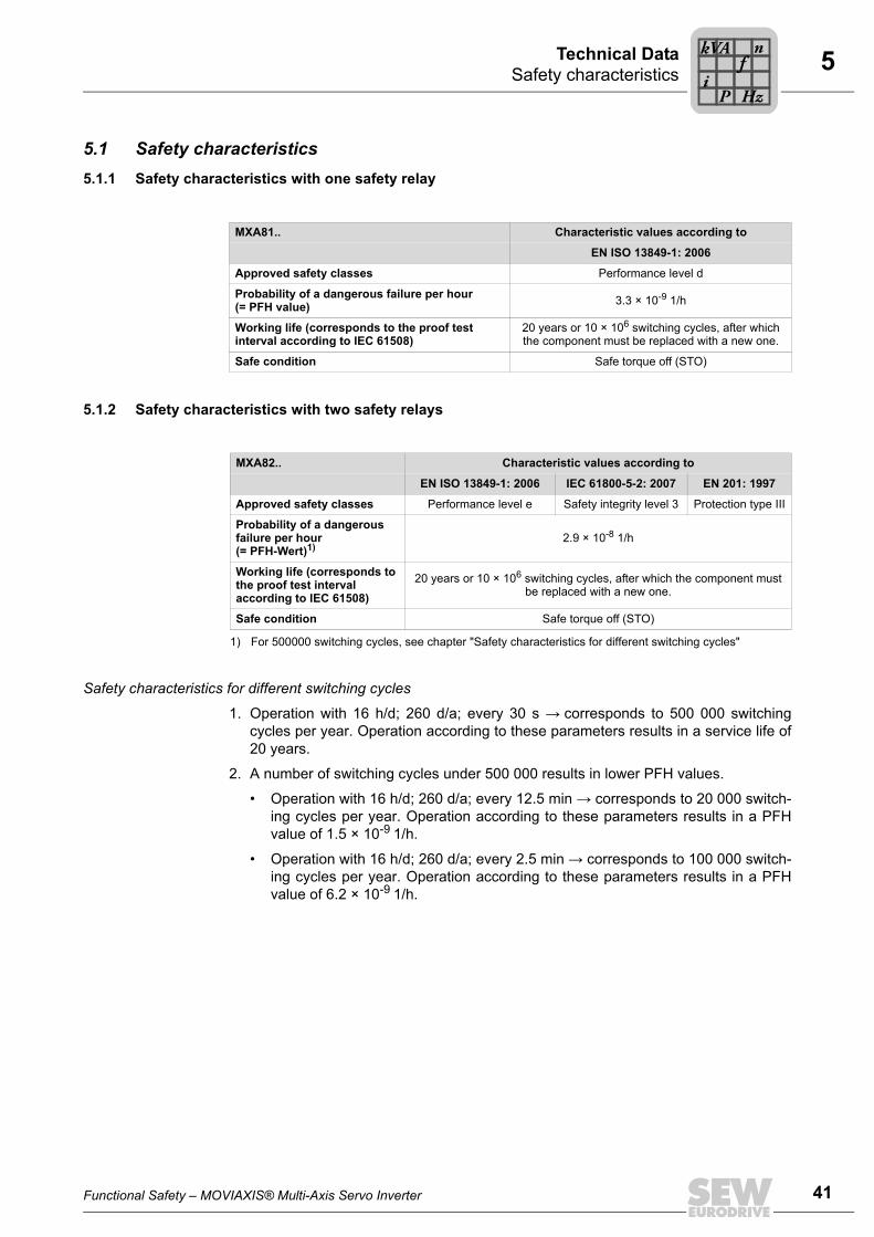
5.1 Safety characteristics5.1.1 Safety characteristics with one safety relay
5.1.2 Safety characteristics with two safety relays
Safety characteristics for different switching cycles
1. Operation with 16 h/d; 260 d/a; every 30 s → corresponds to 500 000 switchingcycles per year. Operation according to these parameters results in a service life of20 years.
2. A number of switching cycles under 500 000 results in lower PFH values.
• Operation with 16 h/d; 260 d/a; every 12.5 min → corresponds to 20 000 switch-ing cycles per year. Operation according to these parameters results in a PFHvalue of 1.5 × 10⁻⁹ 1/h.
• Operation with 16 h/d; 260 d/a; every 2.5 min → corresponds to 100 000 switch-ing cycles per year. Operation according to these parameters results in a PFHvalue of 6.2 × 10⁻⁹ 1/h.
MXA81.. Characteristic values according to
EN ISO 13849-1: 2006
Approved safety classes Performance level d
Probability of a dangerous failure per hour (= PFH value) 3.3 × 10⁻⁹ 1/h
Working life (corresponds to the proof test interval according to IEC 61508)
20 years or 10 × 106 switching cycles, after which the component must be replaced with a new one.
Safe condition Safe torque off (STO)
MXA82.. Characteristic values according to
EN ISO 13849-1: 2006 IEC 61800-5-2: 2007 EN 201: 1997
Approved safety classes Performance level e Safety integrity level 3 Protection type III
Probability of a dangerous failure per hour (= PFH-Wert)1)
1) For 500000 switching cycles, see chapter "Safety characteristics for different switching cycles"
2.9 × 10⁻⁸ 1/h
Working life (corresponds to the proof test interval according to IEC 61508)
20 years or 10 × 106 switching cycles, after which the component must be replaced with a new one.
Safe condition Safe torque off (STO)
Functional Safety – MOVIAXIS® Multi-Axis Servo Inverter
Pi
fkVA
Hz
n
41
42
Index
Index
AApproved units .......................................................14
CCopyright..................................................................7
DDisconnection of a single drive ..............................24
STO according to PL d (EN 13849-1) ................24Disconnection of group drives................................34
Requirements.....................................................34Disconnection of single drive
Requirements.....................................................23
EEmbedded safety notes ...........................................6Exclusion of liability ..................................................6
GGroup disconnection
Max. number of axis modules ............................34STO according to PL d (EN 13849-1) ................36STO according to PL e (EN 13849-1) ................38With safety relay ................................................35
IInstallation
Requirements.....................................................16Installation, requirements.......................................16Integrated safety technology
Restrictions ........................................................12
NNameplate, status line ...........................................15Notes
Designation in the documentation........................6Number of MOVIAXIS® axis modules for group
disconnection .....................................................34
OOperation, requirements ........................................20
PPermitted units
Status line of the nameplate ..............................15Units with one safety relay.................................14Units with two safety relays ...............................14
PLC-FDO, requirements ........................................23Product names.........................................................7
RRequirements
Installation..........................................................16Operation ...........................................................20
Rights to claim under limited warranty.....................6
SSafe stop 1 (SS1) ..................................................11Safe torque off (STO) ............................................10Safety concept ...................................................8, 10
Safety inputs ........................................................9Safety controller, requirements..............................19Safety inputs ............................................................9Safety notes
Designation in the documentation .......................6Structure of the embedded safety notes..............6Structure of the section-related safety notes .......6
Safety relays, requirements ...................................23Section-related safety notes ....................................6Signal words in safety notes ....................................6Single disconnection
SS1 according to PL d (EN 13849-1) ................27SS1 according to PL e (EN13849-1) .................32STO according to PL e (EN13849-1).................30
SS1 according to PL d (EN 13849-1) ....................27SS1 according to PL e (EN13849-1) .....................32SS1 (Safe Stop 1)..................................................11Status line of the nameplate ..................................15STO according to PL d (EN 13849-1)..............24, 36STO according to PL e (EN 13849-1)....................38STO according to PL e (EN13849-1).....................30STO (safe torque off) .............................................10
TTrademarks..............................................................7
Functional Safety – MOVIAXIS® Multi
-Axis Servo Inverter
Index
UUnits with one safety relay .....................................14Units with two safety relays....................................14Units, approved......................................................14
VVerification of disconnection devices .....................20
Verifying safety functions.......................................20
WWiring instructions
PL d according to EN ISO 13849-1 ...................17Protection type III according to EN 201 .............18SIL3 according to IEC 61800-5-2 ......................18
Functional Safety – MOVIAXIS® Multi-Axis Servo Inverter
43


SEW-EURODRIVE—Driving the world
SEW-EURODRIVEDriving the world
www.sew-eurodrive.com
SEW-EURODRIVE GmbH & Co KGP.O. Box 3023D-76642 Bruchsal/GermanyPhone +49 7251 75-0Fax +49 7251 [email protected]