
Movable and launched bridges: recent realizations and ... · PDF fileMovable and launched...
11
Movable and launched bridges: recent realizations and improved techniques S. Hernández & A. N. Fontán Structural Mechanics Group, School of Civil Engineering, University of A Coruña, Spain Abstract Most bridges are fixed structures designed to provide continuity in roads, railways or any other kind of network systems. Nevertheless in some cases the design of the bridge or traffic requirements at the bridge’s location involves some level of mobility to the structure. In this paper, two examples of non fixed structures, namely movable bridges and launched bridges, are described. In both cases several examples are posed and the circumstances related to the conception and the design of these constructions are described. Keywords: movable structures, launched bridges, innovative bridge design, design optimization. 1 Introduction Most bridges are fixed constructions, designed to provide continuity in highways, railways or any other class of network systems. Nevertheless in some cases these structures are required to modify their geometry to allow some traffic below or across them. This circumstance complicates the design process as the structure needs to be stable and safe not only in its usual shape but also in its modified position. These kinds of bridges, entitled movable bridges, have been erected in several countries in recent decades. There are several means to design a movable bridge and they will be described in the following paragraph. Another class of bridge that contains the necessity of being translated before it stands in its final location is the so-called launched bridge. These structures are built not far from their position but they have to be rotated or translated from the construction site to their definite spot. Due to the capability of these structures Mobile and Rapidly Assembled Structures IV 245 doi:10.2495/MAR140201 www.witpress.com, ISSN 1743-3509 (on-line) WIT Transactions on The Built Environment, Vol 136, © 2014 WIT Press
Transcript of Movable and launched bridges: recent realizations and ... · PDF fileMovable and launched...

Movable and launched bridges: recent realizations and improved techniques
S. Hernández & A. N. Fontán Structural Mechanics Group, School of Civil Engineering, University of A Coruña, Spain
Abstract
Most bridges are fixed structures designed to provide continuity in roads, railways or any other kind of network systems. Nevertheless in some cases the design of the bridge or traffic requirements at the bridge’s location involves some level of mobility to the structure. In this paper, two examples of non fixed structures, namely movable bridges and launched bridges, are described. In both cases several examples are posed and the circumstances related to the conception and the design of these constructions are described. Keywords: movable structures, launched bridges, innovative bridge design, design optimization.
1 Introduction
Most bridges are fixed constructions, designed to provide continuity in highways, railways or any other class of network systems. Nevertheless in some cases these structures are required to modify their geometry to allow some traffic below or across them. This circumstance complicates the design process as the structure needs to be stable and safe not only in its usual shape but also in its modified position. These kinds of bridges, entitled movable bridges, have been erected in several countries in recent decades. There are several means to design a movable bridge and they will be described in the following paragraph. Another class of bridge that contains the necessity of being translated before it stands in its final location is the so-called launched bridge. These structures are built not far from their position but they have to be rotated or translated from the construction site to their definite spot. Due to the capability of these structures
Mobile and Rapidly Assembled Structures IV 245
doi:10.2495/MAR140201
www.witpress.com, ISSN 1743-3509 (on-line) WIT Transactions on The Built Environment, Vol 136, © 2 014 WIT Press

they have captured the interest of practitioners and researchers [1–4] with the aim of using the most up to date design methodologies in the design of these structures.
2 Movable bridges
There are several classes of movable bridges [5], depending on the type of displacement carried out to modify the location of the bridge. The more frequently used versions are: - Bascule bridges - Swing bridges - Vertical lift bridges - Tilt bridges - Convertible bridges - Folding bridges a) Bascule bridges: These bridges move because they have hinges at both ends that allow a rotation from a horizontal axis perpendicular to the traffic direction of the bridge. They are very usual in harbors. Some examples are the Leon de Carranza Bridge in the bay of Cadiz (Spain) or the Galata Bridge in Istanbul (Turkey). Also, two more bascule bridges recently built in Spain are presented in Figure 1.
a) b)
Figure 1: Examples of bascule bridges: a) Barcelona Harbour, b) Valencia Harbour.
b) Swing bridges: These bridges rotate with respect to a vertical axis. It can be located at one end of the structure or in the middle. Sometimes the span of the movable bridge can be very long. The El Ferdan Bridge over the Suez Canal has a main span of about 300 m. More recently the floating and swing bridge in the Osaka Harbour in Japan has a main span of 280 m. Other examples are the Sungai Prai River Bridge (Malaysia) or the Shatt-Al-Arab Bridge (Iraq). Figure 2 shows some pictures of this class of bridges.
246 Mobile and Rapidly Assembled Structures IV
www.witpress.com, ISSN 1743-3509 (on-line) WIT Transactions on The Built Environment, Vol 136, © 2 014 WIT Press

a) b)
c) d)
Figure 2: Examples of swing bridges: a) Osaka Harbour Bridge, b) Dimensions of Osaka Harbour Bridge, c) Naestved Bridge, usual shape, d) Naestved Bridge, rotated shape.
c) Vertical lift bridges: These bridges modify their regular geometry by lifting vertically one of more spans. The Guaiba River Bridge at Porto Allegre (Brazil) and the Hawthorne Bridge (USA) belong to this typology. Recent examples include the Chaban Delmas Bridge, shown in Figure 3 and inaugurated in 2013 in Bordeaux (France) with a very innovative design.
a) b)
Figure 3: Example of vertical lift bridge. Chaban Delmas Bridge: a) view of the bridge, b) bridge after central span lifting.
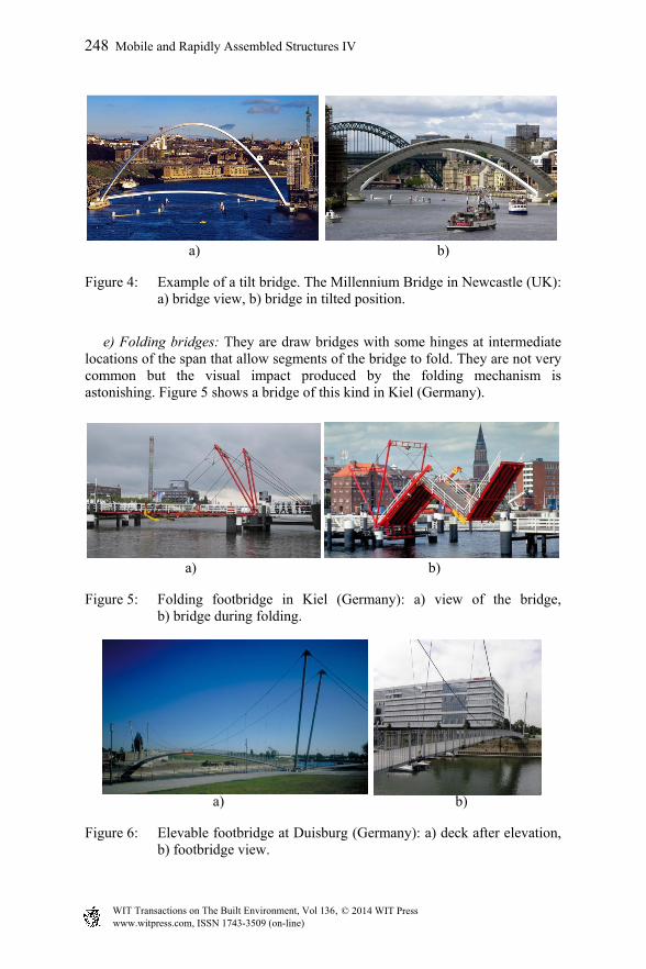
d) Tilt bridges: This version of movable structures rotates with respect to a horizontal axis in the longitudinal direction of the bridge. Such movement produces a drastic change in bridge geometry. A recent example can be found in the Millennium Bridge in Newcastle (U.K) shown in Figure 4.
Mobile and Rapidly Assembled Structures IV 247
www.witpress.com, ISSN 1743-3509 (on-line) WIT Transactions on The Built Environment, Vol 136, © 2 014 WIT Press
a) b)
Figure 4: Example of a tilt bridge. The Millennium Bridge in Newcastle (UK): a) bridge view, b) bridge in tilted position.
e) Folding bridges: They are draw bridges with some hinges at intermediate locations of the span that allow segments of the bridge to fold. They are not very common but the visual impact produced by the folding mechanism is astonishing. Figure 5 shows a bridge of this kind in Kiel (Germany).
a) b)
Figure 5: Folding footbridge in Kiel (Germany): a) view of the bridge, b) bridge during folding.
a) b)
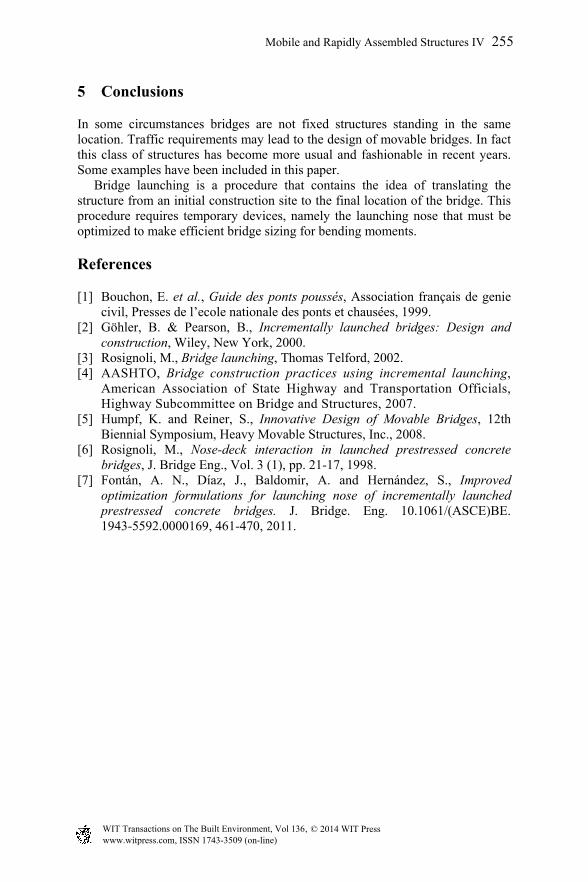
Figure 6: Elevable footbridge at Duisburg (Germany): a) deck after elevation, b) footbridge view.
248 Mobile and Rapidly Assembled Structures IV
www.witpress.com, ISSN 1743-3509 (on-line) WIT Transactions on The Built Environment, Vol 136, © 2 014 WIT Press

f) Elevable bridges: This version of movable bridges differ from vertical lift bridges. Instead of translating vertically the span a constant magnitude each point of the bridge is displaced a different value and thus changing the longitudinal shape of the elevable span. An interesting example in the footbridge at Duisburg, shown in Figure 6. That structure is a suspension footbridge with two pylons at each end that are hinged at the bottom. By introducing an additional force at the cables the pylons rotate and raise the main cable what leads to a vertical displacement of the footbridge deck as shown in the figure.
3 Launched bridges
Bridge construction by launching procedures is a usual solution when the structure crosses over deep valleys or not accessible locations, in general. In that case the bridge is built in one side, or half bridge is made at each end. Then the structure is translated longitudinally until placing it in its final location. The most common version of launching is the Incremental Lauching Method (ILM) that consist on building a segment of the bridge deck and afterwards moving forward the structure. The procedure is repeated several times until the full bridge is completed. In order to diminish the value of bending moments in the bridge deck during launching a device named launching nose is placed in front of the deck. This device is a steel structure much lighter than the bridge deck and its proper size is very important for the efficiency of the construction procedure. Examples of bridges built by ILS system with concrete and composite decks are presented in Figure 7.
a) b)
Figure 7: Examples of bridges built using ILS: a) concrete deck bridge, b) bridge with composite deck.
A recent example of launched bridge is the Millau viaduct, in France. It is a continuous cable stayed bridge with seven towers and spans of 342 m length. The bridge has steel deck and was built from both sides of the valley by assembling deck segments and launching the structure over neoprene-Teflon bearings on the top of the intermediate piers. A short launching nose was
Mobile and Rapidly Assembled Structures IV 249
www.witpress.com, ISSN 1743-3509 (on-line) WIT Transactions on The Built Environment, Vol 136, © 2 014 WIT Press

installed at the front of the bridge because the tip of it was connected to the top of a tower that was built at the beginning of the bridge construction and collaborated in decreasing bridge deflections and bending moments distribution. Some details of the bridge after completion and at different stages of the construction are shown in Figure 8.
a) b)
c) d)
Figure 8: Millau Viaduct: a) view of the bridge, b) launching nose at a temporary pier, c) towers on temporary and final piers, d) bridge under construction with only two towers.
4 Launching nose optimization is prestressed concrete bridges
The problem of finding out an efficient length for the launching nose was first studied by Rosignoli [6]. The problem was formulated defining the following parameters: - qn: launching nose unit weight, - En·In: launching nose bending stiffness, - Ln: launching nose length, - q: deck unit weight, - E·I: deck bending stiffness, - L: deck span length.
250 Mobile and Rapidly Assembled Structures IV
www.witpress.com, ISSN 1743-3509 (on-line) WIT Transactions on The Built Environment, Vol 136, © 2 014 WIT Press

In the literature, L is commonly considered to be same for all bridge spans. Defining the launch progression by the distance x measured from the front end of the deck to the foremost pier B and the dimensionless parameter α = x/L, two phases are established during each launching stage as presented in Figure 9: - Phase 1 (Figure 9.a): /n0 1 L L
During this phase, the frontal part of the deck and the launching nose constitute a cantilever, and the bending moment at support B can be calculated as a statically determinate structure. - Phase 2 (Figure 9.b): /n1 L L 1
During this phase, the launching nose reaches and passes over a new pier A, which is ahead of support B. The bending moment at support B must be calculated by solving the statically indeterminate nose-deck structural system. As an approximation, the number of equal spans behind support C is assumed to be very large to assimilate the system to a continuous beam with infinite spans.
a) b)
Figure 9: Phases in launching procedure: a) cantilever phase, b) continuous beam phase.
For the specific case when qn/q = 0.1, Rosignoli found out using a trial and error method that the best length for the launching nose was Ln/L = 0.65 as it made equal the maximum value of bending moment at point B in both launching phases as it can be seen in Figure 10.
Figure 10: Bending moment MB during launching procedure.
Mobile and Rapidly Assembled Structures IV 251
www.witpress.com, ISSN 1743-3509 (on-line) WIT Transactions on The Built Environment, Vol 136, © 2 014 WIT Press

It can be observed in this figure that the relative stiffness between launching nose and bridge deck must be En·In/E·I > 0.2 or other ways the maximum value of bending moment during the second phase of launching will appear before the end of the procedure which is undesirable. The same problem has been solved as an optimization problem as follows:
- Design variables: /x L , /L nL L , /EI n nE I E I
- Objective function: min max phase1 phase2B L BM 1 M , where phase1
BM
and phase2BM are the evolution of bending moment at support B in Phase 1 and
2 respectively. This optimization problem can be solved by an equivalent formulation as
min2
1 2F f f (1)
subject to constraints
1 LL L EI
g 1 01 1 0 1 0 1
0 1
(2)
where
( ) / ( ) /2 21 B L 2 B Lf M 1 q L f M q L 1 1
(3)
The solution obtained is presented in Figure 11 and corresponds to the following numerical values
. . . .n n n BL EI
L E I Mx0 924 0 666 0 323 0 1003
L L E I q L
(4)
Figure 11: Optimum values of MB for qn/q = 0.1.
252 Mobile and Rapidly Assembled Structures IV
www.witpress.com, ISSN 1743-3509 (on-line) WIT Transactions on The Built Environment, Vol 136, © 2 014 WIT Press

Insight considerations on this problem allowed to find that the formulation stated by Rosignoli could be improved because:
- Perhaps the optimum could be obtained just by diminishing the maximum bending moment during the launching.
- Perhaps the formulation needed to include the value of bending moment at support C.
- Perhaps the formulation should be made considering not the values of the bending moments but the stress values top and bottom fibres in the concrete deck.
- Perhaps the formulation should include the distribution of bending moment inside the bridge front span, that have values of opposite sign to the bending moments at the supports.
- Perhaps the formulation should include a relationship between the unit weight and the length of the launching nose.
- A case with the following numerical values was used by Fontán and Hernández [7] to formulate the optimization problem considering the full set of considerations aforementioned.
3 350 ; 150 / ; 5.01 ; 7.58 ; 0.018; 0.030i s m ML m q kN m W m W m k k (5)
being Wi and Ws the strength modulus at the bottom and top fibers of the deck
2n
m Mn
qk k
L (6)
The formulation of the problem becomes
- Design variables: /x L , /L nL L , /EI n nE I E I , /q nq q
- Objective function: - -
, , ,
min max
, ,
phase1 phase2 phase1 phase2B L B C C
s s s s
phase2 phase1 phase2AB BC BC
i i i
M 1 M M 0 M
W W W W
M M 0 M
W W W
(7)
This minmax problem, is solved by defining a new design variable αγ:
min (8)
Mobile and Rapidly Assembled Structures IV 253
www.witpress.com, ISSN 1743-3509 (on-line) WIT Transactions on The Built Environment, Vol 136, © 2 014 WIT Press

subject to the followings constraints:
3 41 21 2 3 4
s s s s
2 25 6 75 6 7
i i i
28 L mL 9 L q q
2M10 q L L EI
f ff fg 0 g 0 g 0 g 0
W W W W
f f fg 0 g 0 g 0 10 10
W W W
g 1 0 k1 1 g L 0 0 1
0 1 q
kg L 0 0 1 0 1
q
(9)
where f1 and f2 are as defined in Eq. (3), with:
C C AB BC BC3 4 5 6 72 2 2 2 2
M 0 M M M 0 Mf f f f f
q L q L q L q L q L
(10)
The solution is presented graphically in Figure 12. The numerical results are
0.748 0.092 0.168L EI q (11)
. at . . at
CB2 32 2
MMf 0 1103 0 588 f 0 0931 0
q L q L
(12)
Figure 12: Optimum values of MB in the enhanced formulation of optimization.
254 Mobile and Rapidly Assembled Structures IV
www.witpress.com, ISSN 1743-3509 (on-line) WIT Transactions on The Built Environment, Vol 136, © 2 014 WIT Press
5 Conclusions
In some circumstances bridges are not fixed structures standing in the same location. Traffic requirements may lead to the design of movable bridges. In fact this class of structures has become more usual and fashionable in recent years. Some examples have been included in this paper. Bridge launching is a procedure that contains the idea of translating the structure from an initial construction site to the final location of the bridge. This procedure requires temporary devices, namely the launching nose that must be optimized to make efficient bridge sizing for bending moments.
References
[1] Bouchon, E. et al., Guide des ponts poussés, Association français de genie civil, Presses de l’ecole nationale des ponts et chausées, 1999.
[2] Göhler, B. & Pearson, B., Incrementally launched bridges: Design and construction, Wiley, New York, 2000.
[3] Rosignoli, M., Bridge launching, Thomas Telford, 2002. [4] AASHTO, Bridge construction practices using incremental launching,
American Association of State Highway and Transportation Officials, Highway Subcommittee on Bridge and Structures, 2007.
[5] Humpf, K. and Reiner, S., Innovative Design of Movable Bridges, 12th Biennial Symposium, Heavy Movable Structures, Inc., 2008.
[6] Rosignoli, M., Nose-deck interaction in launched prestressed concrete bridges, J. Bridge Eng., Vol. 3 (1), pp. 21-17, 1998.
[7] Fontán, A. N., Díaz, J., Baldomir, A. and Hernández, S., Improved optimization formulations for launching nose of incrementally launched prestressed concrete bridges. J. Bridge. Eng. 10.1061/(ASCE)BE. 1943-5592.0000169, 461-470, 2011.
Mobile and Rapidly Assembled Structures IV 255
www.witpress.com, ISSN 1743-3509 (on-line) WIT Transactions on The Built Environment, Vol 136, © 2 014 WIT Press


