MouseLight: Bimanual Interactions on Digital Paper …tovi/papers/chi2010_mouselight.pdf ·...
10
MouseLight: Bimanual Interactions on Digital Paper Using a Pen and a Spatially-Aware Mobile Projector Hyunyoung Song 1,2,3 , Francois Guimbretiere 2,3 , Tovi Grossman 1 , George Fitzmaurice 1 1 Autodesk Research 210 King St. East, Toronto, ON, M5A 1J7 Canada {firstname.lastname}@autodesk.com 2 University of Maryland Department of Computer Science Human-Computer Interaction Lab College Park, MD 20742 USA [email protected] 3 Cornell University Computing and Information Science 301 College Ave, Ithaca NY 14850 USA [email protected] ABSTRACT MouseLight is a spatially-aware standalone mobile projector with the form factor of a mouse that can be used in combination with digital pens on paper. By interacting with the projector and the pen bimanually, users can visualize and modify the virtually augmented contents on top of the paper, and seamlessly transition between virtual and physical information. We present a high fidelity hardware prototype of the system and demonstrate a set of novel interactions specifically tailored to the unique properties of MouseLight. MouseLight differentiates itself from related systems such as PenLight in two aspects. First, MouseLight presents a rich set of bimanual interactions inspired by the ToolGlass interaction metaphor, but applied to physical paper. Secondly, our system explores novel displaced interactions, that take advantage of the independent input and output that is spatially aware of the underneath paper. These properties enable users to issue remote commands such as copy and paste or search. We also report on a preliminary evaluation of the system, which produced encouraging observations and feedback. ACM Classification Keywords H5.2. [User Interfaces]: Input devices and strategies General Terms: Design, Human Factors Author Keywords Digital pen input, spatially-aware display, mobile projector INTRODUCTION The field of Augmented Reality [25, 33, 36] has demonstrated the interesting properties which arise from augmenting physical artifacts with virtual imagery. In particular, Fitzmaurice [8] thoroughly describes the benefits of overlaying virtual information in situ of physical environments when the digital system is aware of its location. This idea has been extended with different display and tracking technologies [6, 19] to not only visualize, but also to manipulate, virtual imagery in the context of a physical environment. Paper has been one of the most popular mediums to virtually augment [1, 18, 29, 36] due to its unique physical properties such as ubiquity, mobility, and scalability [26]. Recently, virtual interactions on paper gained further interest due to the introduction of emerging digital pen technologies such as Anoto [2]. An Anoto-based digital pen [10, 17] can capture and interpret what users write using the embedded camera. When combined with visual feedback [15, 17, 27, 29], the pen can serve as a proxy to access virtual information associated with the physical paper. The virtual information can then be updated on paper and the next iteration begins. Depending on the properties of the visual feedback, different virtual interactions on paper are possible. One example, PenLight [29], simulates a mobile projector mounted on a digital pen and allows a dynamic visual overlay to be displayed on top of a physical printout. This increases the “functionality” of the paper, allowing a user to interact with virtual content such as ink and auxiliary data. PenLight’s integration of pen input and projector output into a single device improves the mobility of the device, but at the cost of fixing the pen tip to a single point Permission to make digital or hard copies of all or part of this work for personal or classroom use is granted without fee provided that copies are not made or distributed for profit or commercial advantage and that copies bear this notice and the full citation on the first page. To copy otherwise, or republish, to post on servers or to redistribute to lists, requires prior specific permission and/or a fee. CHI 2010, April 10–15, 2010, Atlanta, Georgia, USA. Copyright 2010 ACM 978-1-60558-929-9/10/04....$10.00. Figure 1 Conceptual sketch of the MouseLight system. (Courtesy of Kyle Runcimen) CHI 2010: Displays Where You Least Expect Them April 10–15, 2010, Atlanta, GA, USA 2451
Transcript of MouseLight: Bimanual Interactions on Digital Paper …tovi/papers/chi2010_mouselight.pdf ·...

MouseLight: Bimanual Interactions on Digital Paper Using a Pen and a Spatially-Aware Mobile Projector
Hyunyoung Song1,2,3
, Francois Guimbretiere2,3
, Tovi Grossman1, George Fitzmaurice
1
1Autodesk Research 210 King St. East,
Toronto, ON, M5A 1J7 Canada {firstname.lastname}@autodesk.com
2University of Maryland Department of Computer Science Human-Computer Interaction Lab
College Park, MD 20742 USA [email protected]
3Cornell University Computing and Information Science
301 College Ave, Ithaca NY 14850 USA
ABSTRACT
MouseLight is a spatially-aware standalone mobile projector with the form factor of a mouse that can be used in combination with digital pens on paper. By interacting with the projector and the pen bimanually, users can visualize and modify the virtually augmented contents on top of the paper, and seamlessly transition between virtual and physical information. We present a high fidelity hardware prototype of the system and demonstrate a set of novel interactions specifically tailored to the unique properties of MouseLight. MouseLight differentiates itself from related systems such as PenLight in two aspects. First, MouseLight presents a rich set of bimanual interactions inspired by the ToolGlass interaction metaphor, but applied to physical paper. Secondly, our system explores novel displaced interactions, that take advantage of the independent input and output that is spatially aware of the underneath paper. These properties enable users to issue remote commands such as copy and paste or search. We also report on a preliminary evaluation of the system, which produced encouraging observations and feedback.
ACM Classification Keywords
H5.2. [User Interfaces]: Input devices and strategies
General Terms:
Design, Human Factors
Author Keywords
Digital pen input, spatially-aware display, mobile projector
INTRODUCTION
The field of Augmented Reality [25, 33, 36] has demonstrated the interesting properties which arise from augmenting physical artifacts with virtual imagery. In particular, Fitzmaurice [8] thoroughly describes the benefits of overlaying virtual information in situ of physical environments when the digital system is aware of
its location. This idea has been extended with different display and tracking technologies [6, 19] to not only visualize, but also to manipulate, virtual imagery in the context of a physical environment. Paper has been one of the most popular mediums to virtually augment [1, 18, 29, 36] due to its unique physical properties such as ubiquity, mobility, and scalability [26].
Recently, virtual interactions on paper gained further interest due to the introduction of emerging digital pen technologies such as Anoto [2]. An Anoto-based digital pen [10, 17] can capture and interpret what users write using the embedded camera. When combined with visual feedback [15, 17, 27, 29], the pen can serve as a proxy to access virtual information associated with the physical paper. The virtual information can then be updated on paper and the next iteration begins. Depending on the properties of the visual feedback, different virtual interactions on paper are possible.
One example, PenLight [29], simulates a mobile projector mounted on a digital pen and allows a dynamic visual overlay to be displayed on top of a physical printout. This increases the “functionality” of the paper, allowing a user to interact with virtual content such as ink and auxiliary data. PenLight’s integration of pen input and projector output into a single device improves the mobility of the device, but at the cost of fixing the pen tip to a single point
Permission to make digital or hard copies of all or part of this work for personal or classroom use is granted without fee provided that copies are not made or distributed for profit or commercial advantage and that copies bear this notice and the full citation on the first page. To copy otherwise, or republish, to post on servers or to redistribute to lists, requires prior specific permission and/or a fee. CHI 2010, April 10–15, 2010, Atlanta, Georgia, USA. Copyright 2010 ACM 978-1-60558-929-9/10/04....$10.00.
Figure 1 Conceptual sketch of the MouseLight system.
(Courtesy of Kyle Runcimen)
CHI 2010: Displays Where You Least Expect Them April 10–15, 2010, Atlanta, GA, USA
2451

of the projector screen. As a result, users cannot make annotations and overlay virtual content independent of one another. In other words, users may have to alternate between using the device as a pen and as a projector, which prevents seamless paper interactions.
We present MouseLight, to further explore virtual interactions on paper, by decoupling the pen input and the projector output. MouseLight is a standalone, location aware mobile projector with the form factor of a mouse that can be used in combination with digital pens on paper (Figure 1). The MoughtLight system interprets pen strokes to visualize, modify and transfer virtual content on top of the paper. As our first contribution, we implemented a high fidelity hardware prototype using a state-of-the-art miniature laser projector [20]. As a second contribution, we explored two interaction paradigms on paper interfaces which reflect MouseLight hardware properties such as spatial-awareness and independent input and output. First, we explored a toolglass metaphor on paper. Virtual toolglass functions such as copy and paste, search, camera, color and drafting palettes support seamless virtual content creation, transfer and modification while users annotate on them using a digital pen. Second, we explore novel displaced interaction. Since both input and output devices are aware of underneath page information, contextual links between these two locations are created. Such information can be used to remotely manipulate the projection screen (ex. remote copy and paste) or to provide additional parameters for operations such as search. Our preliminary evaluations confirmed that our hardware prototype was intuitive to use. In addition, users commented that the two interaction paradigms are interesting and that MouseLight improves the usage of paper by reducing the boundaries between the physical and virtual information spaces.
RELATED WORK
Digital Pen Computing Digital pen applications propose different ways to reduce the gap between documents and their paper-based virtual incarnations. One line of research add digital feedback to the pen input device (i.e. audio [10], visual [16]). The digital pen can serve as a proxy to interface between the physical information space and virtual information space. This enables interactive paper interfaces [15] for users in situations where physical paper properties such as mobility or scalable screen space, are crucial [26]. Another line of research enables command execution on paper. For example, users can execute a command using an icon preprinted on a piece of paper [10, 17] or by creating a gesture [15] with the pen. The concept of updating digital content on paper by interpreting the ink overlaid in the context of printed content and receiving digital feedback has been applied to different domains such as knowledge workers [15, 35], 3D modeling [30], field biologists [40], architecture [29] and musicians[31]. MouseLight extends previous research in digital pen computing by exploring possible virtual interaction on paper interfaces when a
spatially-aware mobile projector is available as a form of digital feedback.
Virtually Augmented Interactions
Many systems, using a range of digital displays, have explored interactions to manipulate virtual data in the context of a physical environment [6, 18, 32, 36, 39]. These augmented display systems can be classified by the different types of displays they utilize (LCD, projector) and by whether those displays are spatially aware. The LCD provides a separate “opaque” screen surface [27, 32, 39] that a user can operate on and query information relevant to the interaction on physical environment [27]. If it is spatially-aware, the position and orientation of the display can provide a physical window-in-hand mechanism to view a virtual 2D [39] or 3D environment [32].
In contrast, the images displayed by projectors are “see-through” in that they can be overlaid on top of a physical surface without causing occlusions [6, 21]. Cao’s system [6] and the Six Sense system [21] demonstrate the use of a mobile, spatially-aware projector with interactive spaces. Along similar lines of mobile, spatially-aware projectors, the PenLight system [29] provides real-time, in-place dynamic visual feedback for digital pen applications [10, 17]. To support mobile usage and minimize device requirements, the projector is integrated into the digital pen. However, this design choice restricts the interactions, since the pen cannot be used independently of the projector. In contrast, MouseLight proposes to separate the input and output, to provide simultaneous input and output of virtual information manipulations in the context of paper.
Several systems have proposed mobile settings in which the projector is not moved while interacting with the system. These include the iLamp system [23], the PlayAnywhere [37] system, the Pokey system [38] and the Bonfire system [12]. In contrast, MouseLight demonstrates how the spatial awareness of a tabletop miniature projector can be used during pen interactions.
ToolGlass Interaction
The bimanual toolglass metaphor [5, 14] uses the non-dominant hand to coarsely position a tool palette while the dominant hand selects items and performs precise operations. MouseLight extends the toolglass metaphor to paper-based interactions.
DESIGN GOALS AND CHARACTERISTICS
MouseLight and PenLight [29] share the same goal; Provide “rich dynamic visual feedback” in paper interactions. PenLight does so by integrating the projector into the pen (Figure 2, Left), which has implications. The pen tip is fixed to a predefined location on the projection screen. Consequently, users cannot write on different parts of the projection screen. In addition, if they want to view interaction results on different parts of the paper, they have to move the device. MouseLight relaxes this restriction by decoupling the input and output devices which gives rise to several new and unique design properties (Figure 2, Right).
CHI 2010: Displays Where You Least Expect Them April 10–15, 2010, Atlanta, GA, USA
2452
Here we first discuss these new characteristics and then describe in detail how our hardware and software interface controls utilize these characteristics.
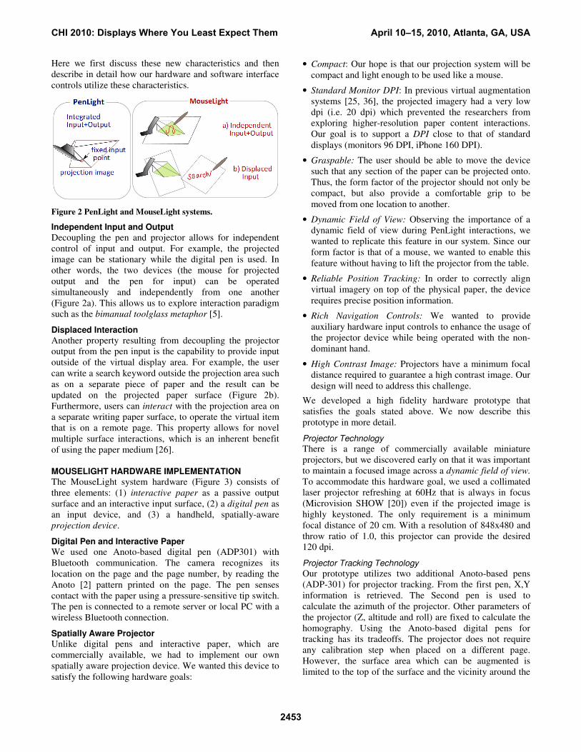
Figure 2 PenLight and MouseLight systems.
Independent Input and Output
Decoupling the pen and projector allows for independent control of input and output. For example, the projected image can be stationary while the digital pen is used. In other words, the two devices (the mouse for projected output and the pen for input) can be operated simultaneously and independently from one another (Figure 2a). This allows us to explore interaction paradigm such as the bimanual toolglass metaphor [5].
Displaced Interaction
Another property resulting from decoupling the projector output from the pen input is the capability to provide input outside of the virtual display area. For example, the user can write a search keyword outside the projection area such as on a separate piece of paper and the result can be updated on the projected paper surface (Figure 2b). Furthermore, users can interact with the projection area on a separate writing paper surface, to operate the virtual item that is on a remote page. This property allows for novel multiple surface interactions, which is an inherent benefit of using the paper medium [26].
MOUSELIGHT HARDWARE IMPLEMENTATION
The MouseLight system hardware (Figure 3) consists of three elements: (1) interactive paper as a passive output surface and an interactive input surface, (2) a digital pen as an input device, and (3) a handheld, spatially-aware projection device.
Digital Pen and Interactive Paper
We used one Anoto-based digital pen (ADP301) with Bluetooth communication. The camera recognizes its location on the page and the page number, by reading the Anoto [2] pattern printed on the page. The pen senses contact with the paper using a pressure-sensitive tip switch. The pen is connected to a remote server or local PC with a wireless Bluetooth connection.
Spatially Aware Projector
Unlike digital pens and interactive paper, which are commercially available, we had to implement our own spatially aware projection device. We wanted this device to satisfy the following hardware goals:
• Compact: Our hope is that our projection system will be compact and light enough to be used like a mouse.
• Standard Monitor DPI: In previous virtual augmentation systems [25, 36], the projected imagery had a very low dpi (i.e. 20 dpi) which prevented the researchers from exploring higher-resolution paper content interactions. Our goal is to support a DPI close to that of standard displays (monitors 96 DPI, iPhone 160 DPI).
• Graspable: The user should be able to move the device such that any section of the paper can be projected onto. Thus, the form factor of the projector should not only be compact, but also provide a comfortable grip to be moved from one location to another.
• Dynamic Field of View: Observing the importance of a dynamic field of view during PenLight interactions, we wanted to replicate this feature in our system. Since our form factor is that of a mouse, we wanted to enable this feature without having to lift the projector from the table.
• Reliable Position Tracking: In order to correctly align virtual imagery on top of the physical paper, the device requires precise position information.
• Rich Navigation Controls: We wanted to provide auxiliary hardware input controls to enhance the usage of the projector device while being operated with the non-dominant hand.
• High Contrast Image: Projectors have a minimum focal distance required to guarantee a high contrast image. Our design will need to address this challenge.
We developed a high fidelity hardware prototype that satisfies the goals stated above. We now describe this prototype in more detail.
Projector Technology
There is a range of commercially available miniature projectors, but we discovered early on that it was important to maintain a focused image across a dynamic field of view.
To accommodate this hardware goal, we used a collimated laser projector refreshing at 60Hz that is always in focus (Microvision SHOW [20]) even if the projected image is highly keystoned. The only requirement is a minimum focal distance of 20 cm. With a resolution of 848x480 and throw ratio of 1.0, this projector can provide the desired 120 dpi.
Projector Tracking Technology
Our prototype utilizes two additional Anoto-based pens (ADP-301) for projector tracking. From the first pen, X,Y information is retrieved. The Second pen is used to calculate the azimuth of the projector. Other parameters of the projector (Z, altitude and roll) are fixed to calculate the homography. Using the Anoto-based digital pens for tracking has its tradeoffs. The projector does not require any calibration step when placed on a different page. However, the surface area which can be augmented is limited to the top of the surface and the vicinity around the
CHI 2010: Displays Where You Least Expect Them April 10–15, 2010, Atlanta, GA, USA
2453

paper (Figure 4) because the projector location can be calculated only when both pens are on top of the pattern.
Figure 3 Our proof of concept MouseLight system. Our system consists of three main components: a digital pen, digital paper and spatially-aware projector.
Figure 4 Traceable Projection Areas.
Figure 5 Casing and Mirrors. Diagram of how the lightpath was folded using two front surface mirrors in two different viewing modes (Left: Focus view, Right: Context view).
Casing and Mirrors
To place the projector in a stable position parallel to the ground, we used two front surface mirrors to fold the light path onto the paper. The mirrors also provide the minimum required focal distance of the projector technology to produce a high contrast image. Hardware components were mounted on a laser cut acrylic casing. The projector was fit to the bottom and the Anoto pens were mounted on both sides. The resulting active projection area is 12x15 cm with a light path length of 20cm. The projection area is 1 cm in front of the two pen sensors in its default focus view (Figure 5, Left) and 12 cm in front in an additional context view, which we describe below (Figure 5, Right).
Auxiliary Hardware Input
To provide rich navigation controls, we fit a wireless mouse on top of the projector. Its scroll wheel will be used to support additional virtual navigations. Further, the mouse casing guides the user in grasping and positioning
the device using the non-dominant hand. The mouse tracking was not used for position information.
As an additional mechanical input device, the top mirror casing swivels up and down on a pivoting rod allowing for changes in the projection angle. Two additional rods act as stoppers and limit swivel to an angle of 15 degrees. Part of the mirror casing extends out, providing a lever to trigger swivels with the index finger of the non-dominant hand. By pushing the lever, the top mirror is lifted to provide a wider field of view. A magnetic switch detects when the handle is in this “context view” state (see Figure 5, Right).
MOUSELIGHT INTERFACE
MouseLight enables seamless virtual and physical information modification and transfer. Here we define the conceptual information layers as well as software and hardware controls that support this fluid transition.
Conceptual Information Layers
When interacting with MouseLight, numerous forms of virtual information can be displayed. PenLight lists different types of virtual information (ink, auxiliary data, user interface elements) and display behaviors (locked in hand vs. locked on surface) from a system design
perspective. Since one goal of MouseLight is to support seamless virtual interaction on top of a paper surface we revisit the PenLight [29] taxonomy from a user perspective
and describe how different virtual information can be manipulated with different display behaviors to offer rich functionality. There are three established layers of information: a printout database layer, a user database layer, and a viewport layer (Figure 6, Left).
• Printout database layer: This layer contains auxiliary
data that is displayed in the context of the printed
content. For example, if a map is printed on a piece of
paper, the printout database consists of vector images
and text labels of either printed content or electronically
stored content. Display elements within the printout
database layer are “locked on-surface” [29] and aligned
with the underlying printout.
• User database layer: This layer includes any new virtual
display element, which is added by the user. For
example, when a user creates ink (annotation or
sketching) on top of the paper, the stroke is inserted into
this layer. The contents of this layer are also locked-on-
surface.
• Viewport layer: This layer contains global UI elements
that enable a user to change the settings of the other two
layers and to operate on them. To keep these elements
available at all times, this layer is not bound to a specific
location of the paper but instead locked in-hand [29]. In
other words, this layer shares its coordinate system with
the projector viewport.
Note that the database layers are page dependent while the viewport layer is application dependent. Hence, when the digital pen and mobile projector are placed on a different
CHI 2010: Displays Where You Least Expect Them April 10–15, 2010, Atlanta, GA, USA
2454

page, the projector displays different content, but the same UI controls.
User Interface Controls
User interface controls (Figure 6, Middle) allow for display, combination, and manipulation of the different layers within the projected region. To access and control the system and toolglass features, the system displays a static menu on the viewport. To manipulate virtual content inside the projected area, contextual marking menus [13] can be displayed within the viewport layer, providing the user with a diverse set of command executions [14].
Static Menu
Inside the viewport layer, the static menu displays two database layer icons at the top border of the projection area, and five toolglass icons at the bottom border.
The database layer menu icons allow users to toggle the
visibility of the virtual database layers (system and
user ). Tapping these icons toggles their visibility. Holding down the pen brings up a marking menu [13] which shows the various display submenus that can be toggled. For example, if working with a campus map, layers such as “library”, “dining”, and “overview” could be the submenus shown that could be activated or deactivated.
There are five toolglass menu icons (colors , copy and
paste , search , camera , and drafting tools ) on the bottom of the viewport representing different transparent toolglasses. Tapping an icon activates the toolglass inside the viewport layer. By moving the MouseLight projector, the user can apply the activated toolglass on top of both database layers. Only one toolglass menu (or feature) can be active at a time, but two or more toolglass palettes of the same feature can be displayed and overlapped.
Contextual Marking Menus
If a toolglass requires users to specify optional parameters to modify objects, contextual pop-up marking menus are displayed in the viewport layer.
The user can select a marking menu item in two ways. First, the user can use the traditional method of moving the pen tip in the direction of the submenu item (mark, Figure 7,
Right). Alternatively, a bimanual method can be used [22] by moving the MouseLight projector with the non-
dominant hand, in the opposite direction of the submenu item, repositioning the menu item under the pen tip (move,
Figure 7, Left). This bimanual technique allows users to make menu selections without leaving a physical ink trail on the paper which is formerly reported as a problem in other interfaces [15].
Figure 7 Menu Selection. Left: Bimanual marking menu Right: traditional marking menu.
Object Selection
If the activated toolglass requires the user to select one or more virtual items, the input from the pen is interpreted as an object selection and not added to the user database layer. To select a single display element the user can tap inside its boundary [10, 17]. If the user wants to choose a command to apply to the selected objects, a marking menu will be displayed, if the pen stays down for more than half a second. To select multiple objects the user can draw a lasso around them [11]. If the user must choose a command to apply to the selected objects, a marking menu will be displayed once the lasso is closed [11].
Ink Management
Our current prototype interprets ink as gestures (no virtual ink added but physical ink added) when the toolglass is activated. Otherwise, ink is recognized as annotations (virtual and physical ink added).
Hardware Control Usage
As described earlier, MouseLight contains auxiliary hardware input (Figure 6, right), to provide improved navigation. Here we describe how our interface utilizes these hardware controls.
• Focus/Context button: To get a larger view of the database layer, user can press this button. Then, the spread of the projection image increases the coverage area by swiveling the top MouseLight mirror. Thus, users can transition between a focus view and a context view [3]. While the projector displays at a constant resolution, the display footprint changes between the focus and
Figure 6 MouseLight Interface. User interface controls allow a user to edit and transfer the virtual contents on paper. Hardware controls improve user in navigating the virtual database layers.
CHI 2010: Displays Where You Least Expect Them April 10–15, 2010, Atlanta, GA, USA
2455

context modes and alters the resulting DPI between high and low resolution (Figure 8). When the context button is pressed, only the objects that do not require a high display DPI are shown.
• ToolGlass Zoom Wheel: To change the size of a
toolglass, the user scrolls the ToolGlass Zoom Wheel.
Figure 8 Layer Navigation using Focus/Context button: Users can change the field of view of the projector.
Both of these additional hardware controls provide
supplemental navigation controls without physically
moving (i.e. vertical hover in PenLight [29]) the device off
the operating surface. Thus, we are able to satisfy our
design goals of rich navigation controls and dynamic field
of view while simultaneously preserving a stable image.
MOUSELIGHT INTERACTIONS
We now describe how our interaction design leveraged the two classes of interaction paradigms (bimanual virtual layer interaction and displaced interaction) described in the design goals section. To contrast the design implications of input and output device relationship (i.g. integrated vs. separate), we selected the most representative digital pen functions of PenLight [29].
Copy and Paste
Independent input and output allows users to click different parts of the viewport and select contextual marking menus very easily. The Copy and Paste feature in MouseLight is designed around this bimanual interaction paradigm. When the copy and paste feature is activated, the user can use the viewport layer as a clipboard to copy a display element from one location to another within the same page or different pages. While similar clipboard concept is demonstrated in PenLight [29], it is difficult to use as users have to operate a cursor fixed to the screen.
There are two steps to copying an item from one location of
the paper surface to another location [24]. The user first
copies the item from the database layer to the viewport
layer. Then, users paste the item into the desired location of
the user database layer by using either of the following
object manipulation methods.
In-place: When the object selection happens inside the
viewport, in-place transfer can occur from database layer
to the viewport thus creating a hyperlink [25] between
the virtual items (Figure 9, Top). By repositioning the
projector to the desired location, the user can then paste
the copied item from the viewport to the database layer.
Displaced: When the object selection occurs outside the
viewport, a displaced copy and paste can be used. When
the item is selected and copied with the pen, its virtual
representation is copied to the viewport layer, and an
active hyperlink [25] is created between the content on
the clipboard and the physical paper. This active
hyperlink enables the user to tap the physical item again
using the dominant hand to access the contextual
marking menu for the copied item. The menu is
displayed in the viewport layer held by the non-dominant
hand which can be controlled by the pen in dominant
hand. Selecting the paste submenu item will paste the
item to the user database layer (Figure 9, Bottom). Such
remote pick-and-drop is not possible if the input and
output is integrated [29] or if the output device isn’t
aware of its location on top of the paper [27].
Figure 9 In-place vs. displaced copy and paste.
Display elements can be copied from one layer to another because different contextual marking menus pop up depending on the underlying information layer. If display elements are located in the database layer, a menu containing “copy” pops up so that the printout database layer can be used as source of copy. Similarly, if a display element is located inside the viewport layer, a menu containing “paste” pops up.
When the user transfers display elements to the viewport layer or to the user database layer, different types of representations can be selected. The user may copy its raw digital representation using the “shape” submenu. If the user wants to copy an iconic representation that displays meta-data such as the direction to its original location, the user can select the “icon” submenu.
For error management, users can correct and undo their copy and paste operation: a) users can select the “delete” submenu on display elements in user database and viewport layers. b) user can reposition display elements within the viewport layer using the “move” submenu. Note that users can either move the pen, or move the MouseLight projector to change the relative location of the display element in the viewport coordinate system.
Search
In-place and displaced manipulations similar to that of copy and paste are also available in the search function. When the search feature is activated, the user can execute a search by either writing or clicking the item to be searched
CHI 2010: Displays Where You Least Expect Them April 10–15, 2010, Atlanta, GA, USA
2456

inside the projection area (in-place) or outside the projection area (displaced).
In comparison to PenLight, users can use the location of the MouseLight projector to provide additional context about the search result while the pen is writing or clicking. For example, when the user is writing “wireless” on a separate sheet of paper, if the projector is placed on top of a campus, buildings with wireless support will be highlighted. If the projector is placed on top of a document, a text bounding box of the search results will be highlighted.
If the result is inside the viewport (Figure 10, Left), then the result is simply highlighted with an outline. If the result is outside the viewport, we use the halo technique [4] to guide the user to move the MouseLight projector to the target region (Figure 10, Right). The focus/context button can also be used to enlarge the projector’s field of view.
There is a variety of ways to initiate a search. Users can write a keyword, or lasso a phrase already written as part of an annotation, or lasso printed text. The search considers not only the printout database layer but also items on the user database layer that the user may have added while previously interacting with the paper.
Figure 10 In-place and displaced search.
Figure 11 Camera feature. User-created strokes trigger video generation and can be used as a playback slide bar.
Camera
When the camera toolglass is activated, users can query
and visualize internally linked images in the viewport layer.
This tool is useful because not all printout database
elements naturally align with the underlying physical
paper. For example, if the user draws a stroke on a
blueprint, the stroke is interpreted as a walk-though path as
in PenLight [29], and a 3D rendering of the building is
displayed in the viewport layer, as the stroke is being
created. When the user is done creating the path, the ink
path serves as a video slide bar for the user to navigate to
the frame that she wants [7].
Using the zoom scroll wheel, the user can change the scale
of the image. Using the focus/context button, the user can
also change the size of the viewport.
Palettes
Up to this point, the features we have described utilize a ToolGlass metaphor to transfer or visualize content from one layer to another. Here, we describe two palette features that provide click-through ToolGlass palettes allowing the user to make changes to the virtual content or physical surface.
Figure 12 Colors feature. Left: Hand icon can be used to move palettes within the viewport. Right: User can click through more than one palette to change the color property.
Color Palette
The Color Palette is used to edit content on the user database layer. There are two types of ToolGlasses visible in the viewport when this feature is activated: the stroke-color toolglass and the fill-color toolglass. To change the property of a virtual display element, the user first aligns the toolglass on top of the printout database layer. Then, the user can tap on the display element through the toolglass and change the corresponding property. To simplify the manipulation, each Toolglass can be resized using the mouse wheel. They can also be moved by clicking the “hand” icon at the bottom of each color palette with the pen, and moving either the mouse or the pen (Figure 12).
Figure 13 Drafting Tool feature. Left: Multiple draft and measuring tools can be used to guide drawing. Right: The viewport scroll wheel allows users to change the scale of the toolglass.
Drafting and Measurement Palettes
In addition to the virtual ink that users can use to trace drawings, drafting and measurement palettes can also be used as virtual “stencils” that help users guide their pen strokes [9]. There are four palettes: two shape tools (rectangle and circle), a protractor, and a French curve [14, 28]. Each of these palettes can be used to guide a user’s designs. As in the case of the color tool palette, the different drafting tools can be used in combination. For
CHI 2010: Displays Where You Least Expect Them April 10–15, 2010, Atlanta, GA, USA
2457

example, the user can overlay the protractor and circle to create a 50° arc.
SOFTWARE IMPLEMENTATION
MouseLight runs on a 3.0 Ghz CPU, with 2 GB RAM and a NVidia Quadro FX 1700 graphics card. The software prototype is written with C#, Windows Presentation Foundation (WPF), on WindowsXP operating system. A WidComm Bluetooth connection was used for the software to communicate with the digital pen in real-time. The projector was connected to the computer as a secondary display.
INITIAL USER EVALUATION
We adopted an iterative design approach and invited users to test our system as its design improved. We now report on the qualitative evaluation of the final two iterations as they used the same evaluation procedure with minimal hardware change. In the first of these studies, an architect and a graphics programmer used a projector tracked by two Wacom pens, as the new generation of Anoto pen used in the current design were not available at the time. In the second study, five college students used our final prototype with Anoto-based projector tracking. The total study lasted for an hour. After 10 minutes of demonstration and training (dominant/non-dominant hand selection, each toolglass feature), participants were asked to complete 16 tasks lasting approximately 30 minutes in total. The tasks covered the main functionality of the MouseLight system (e.g. move drawings of furniture from one page to another). Finally, the subjects completed a questionnaire of 25 questions designed to capture their reaction to system components (e.g. latency of the overlay, different features) using a 7-point Likert scale. Statistical comparisons reported here are based on a t-test with Bonferonni correction to account for alpha inflation. Accordingly only tests with p < .016 should be considered significant. In addition to the questionnaire, the interviewer recorded observations during the evaluation and asked follow-up questions for 30~40 minutes after the subjects completed the questionnaire.
Bimanual Virtual Layer Manipulations
Users were asked to select marking menus (global and context menus) and move the virtual items (palettes and display elements) using both their hands. Users rated their comfort level for dominant hand selection (M=5.9, SD=.61) higher than for non-dominant hand selection (M=5.2, SD=.89), but this was not a significant difference (p=.07). Users commented that they quickly understood the concept of moving the non-dominant hand in the opposite direction of the dominant hand to complete a gesture. However, the relative size of the projector mouse (non-dominant) to the digital pen (dominant) made them less inclined to move their non-dominant hand. Many commented that if our prototype was as small as a commercial mouse, they may have preferred non dominant hand interaction. This result implies that the relative size of
input devices can be a confounding factor in preference between non-dominant and dominant hand interactions.
Users preferred different toolglasses depending on their background. Among the six non-designers, search, camera, copy and paste (in order) were the most highly rated toolglasses. In contrast, the drafting tool was highly appreciated by the architect for two reasons. First, using the drafting tool in their non-dominant hand emulated a movement they were familiar with. Second, designers normally have many physical drafting tools of various sizes. Although our virtual tool cannot provide a physical tool to trace against, the architect appreciated how MouseLight let users arbitrarily combine drafting tools of different sizes.
Displaced Interactions
Users utilized both the in-place and displaced copy and paste techniques to copy virtual content from one page to another. In terms of difficulty, the in-place method (M=5.8, SD=.63) was rated easier to use than the displaced method (M=5.2, SD=.63), but this result was only marginally significant (p=.023). However, in terms of usefulness, the displaced method (M=5.7, SD=.69) was rated as useful as the in-place method (M=5.8, SD=.83, p=.34). In particular, our architect participant commented that if he was working on a large blueprint, the displaced copy and paste method would be more useful.
Virtual Layer Navigation
There are two types of virtual layer navigation in MouseLight: between-page and within-page. Users liked the ability to navigate between different pages using the page recognition capabilities of the pen. Likewise, users found it easy to distinguish which layer the virtual content was on (viewport or database layer). Moving the projector re-enforces which part of the interface is “locked in-hand”. Users also awarded high ratings (M=6.2, SD=.72) to the focus/context button. However, users complained about the location of the projection image being quite far from the device when using the context (wide-view) mode. This is a problem of the projector casing design which will be discussed further in the discussion section.
Visualization
Many participants commented that the two visualization techniques used to indicate off-screen items during a search (hyperlink icons and the halo [4]) were very useful. However, one participant, who was partially color blind, found it harder to distinguish between the colors on the projection image than on an LCD screen. To address this, the color selection in our interface could be modified to make it more appropriate for colorblind users. In terms of the physical ink visuals, one suggestion we received was the use of a retractable pen, so that when making command strokes (such as a lasso), a physical mark would not be left on the paper.
CHI 2010: Displays Where You Least Expect Them April 10–15, 2010, Atlanta, GA, USA
2458

HARDWARE DESIGN
Many users commented on the low brightness of the image. Although our projector has high contrast (above 5000:1) it lacked brightness (10 lumens). As a result, users had to lean in close to the paper surface under daylight conditions to adequately see the virtual content. In addition, the Anoto pattern created a light grey background, absorbing the light further. We believe that energy efficient projectors with higher output capacity will become available shortly. With regard to the Anoto pattern, the pattern could be printed with transparent infrared ink to increase projection contrast.
Another issue is that while the focus/context state was being changed, the projector had an intermediate state where the projection image did not align with the underlying image. This disparity between the two modes can potentially be solved with a sensor that detects the continuous swivel angle.
Different projector-tracking technologies (100Hz for Wacom and 75Hz for Anoto) affected the users rating (6 and 5 for Wacom and M=4.2, SD=1.3 for Anoto) on visual latency where 7 is “no visual latency”. Overall, ratings show that users were able to use our system without experiencing discomfort from the lag introduced by the tracking.
DISCUSSION
Non-dominant Hand Selection
Although non-dominant hand interaction was rated less favorably then dominant hand interaction, most of the users were convinced of its usefulness. First, it prevents unnecessary ink clutter. Second, it allows users to separate inking and command execution in different hands. While introducing a retractable pen can also prevent ink clutter, allocating different types of tasks to different hand is unique to our current design. We believe that these understandings were not reflected in the ratings due to the current size and weight of the device, and limited software interface support. We plan to further explore non-dominant hand interaction.
Focus/Context Control
In our current system, the focus/context toggle button is implemented by simply pivoting the top mirror. This simple mechanical solution comes at a price. There is broader spacing between scan lines and dimmer projection toward the far end of the image. This can be solved by dynamically modifying the scanning pattern of the projector. If dynamic scanning is not supported in hardware, this problem can partially be solved by modulating pixel brightness and keystoning. A dynamic scanning pattern could also help to adjust the position of the image in the "context" setting, so that it does not move away from the base of the mouse. More importantly, it would allow us to use a much smaller cylindrical mirror as the top mirror. This would significantly decrease the visual occlusion the top mirror creates. Thus dynamic scanning
combined with a secondary scroll wheel for continuous context/focus control would be ideal.
MouseLight without the Pen
Although MouseLight was designed to be combined with a digital pen, the system could also be used as a standalone unit to simply augment the paper surface with virtual content. However, independent and displaced interactions will not be available, without a pen to control a cursor. If a simple independent cursor is desired, alternative hardware solutions such as mounting a sensor pad [3, 34] on the projector would be sufficient. Still, displaced interaction will not be possible as the cursor is bound to the screen.
MouseLight vs. PenLight
There are tradeoffs between the MouseLight and PenLight systems. The two interaction paradigms, bimanual interaction and displaced interaction, that we explored in our work come at a cost. In order to use the MouseLight system, the user needs two devices in addition to the paper, restricting usage in mobile situations. The MouseLight system also requires a table-top surface to work on. In contrast, PenLight allows users to use their non-dominant hand to hold the paper while holding the pen (and integrated projector) in their dominant hand which permits greater mobility than MouseLight.
FUTURE WORK
We plan to conduct a formal study comparing MouseLight, PenLight [29], and a system that presents digital content on a slate display [19]. PenLight and MouseLight marks two important instances of virtual augmentation systems in that in one case the input is integrated with the output, and in another case it is separated. There are other dimensions to explore such as display properties: both PenLight and MouseLight rely on see-through interfaces whereas some previous system use separate slate displays. We plan to systematically explore this pen input and visual output design space for digital pen interfaces.
We also plan to extend our current system to better support multiple user scenarios. When more than two users interact with the MouseLight system, new problems develop. As multiple copies of the same document can be annotated by collocated and remote users, a more efficient virtual data management system is required. In addition, users need visual feedback to indicate where the remote user annotated. We are planning to explore strategies to address these problems in collaborative settings.
CONCLUSION
We have presented the MouseLight system which improves the use of digital pen input on paper by augmenting it with a spatially-aware mobile projector. In the realm of paper-based interactions using visual feedback, our system implements previously unexplored hardware properties (a spatially aware, transparent display on paper) and identifies relevant design implications. Our system demonstrates novel displaced interactions, in that the system uses location of input and output devices as contextual
CHI 2010: Displays Where You Least Expect Them April 10–15, 2010, Atlanta, GA, USA
2459

parameters to execute virtual interactions. Also, by exploring a bimanual design, we situate the benefits of previous explorations (such as toolglass [5] and marking menus [13]) that better coexist in the broader context-aware area of paper-intensive practices. Through our initial evaluation, we gathered useful feedback on our hardware design to further improve our prototype. Our evaluation also compared alternative interaction techniques such as dominant and non-dominant hand selection and in-place and displaced copy and paste where we gained useful insights in extending MouseLight interactions. Overall, the findings from our iterative design and evaluation set a solid stage for further expansion in the interesting field of interactive paper interfaces.
ACKNOWLEDGEMENTS
This research was supported in part by the National Science Foundation under Grants IIS-0447703, IIS-0749094 and by a gift of Autodesk Research to the University of Maryland. We would like to thank Corinna Loeckenhoff, Azam Khan, and Adam Bender for their useful comments. We also thank Hod Lipson for letting us use his fabrication resources to create the projector casing. Lastly, we thank our study participants and anonymous CHI reviewers for their feedback.
REFERENCES 1. Aliakseyeu, D., A Computer Support Tool for the Early
Stages of Architectural Design. 2003, Eindhoven University of Technology, The Netherlands.
2. Anoto, Development Guide for Service Enabled by Anoto Functionality
3. Balakrishnan, R. and P. Patel. The PadMouse: facilitating selection and spatial positioning for the non-dominant hand. In Proc. CHI'98. ACM Press. 9 - 16
4. Baudisch, P. and R. Rosenholtz. Halo: a technique for visualizing off-screen objects. In Proc. CHI'03. ACM Press. 481-488
5. Bier, E.A., et al. Toolglass and magic lenses: the see-through interface. In Proc. SIGGRAPH'93. ACM Press. 73 - 80
6. Cao, X. and R. Balakrishnan. Interacting with dynamically defined information spaces using a handheld projector and a pen. In Proc. UIST'06. ACM Press. 225-234
7. Dragicevic, P., et al. Video browsing by direct manipulation. In Proc. CHI'08. ACM Press. 237-246
8. Fitzmaurice, G.W., Situated information spaces and spatially aware palmtop computers. Communications of the ACM, 1993. 36(7): p. 39 - 49.
9. Flagg, M. and J.M. Rehg. Projector-guided painting. In Proc. UIST'06. ACM Press. 235-244
10. Flypentop Computer, http://www.flypentop.com/ 11. Hinckley, K., et al. Design and Analysis of Delimiters for
Selection-Action Pen Gesture Phrases in Scriboli. In Proc. CHI'05. ACM Press. 451-460
12. Kane, S.K., et al. Bonfire: a nomadic system for hybrid laptop-tabletop interaction. In Proc. UIST'09. ACM Press. 129-138
13. Kurtenbach, G., The design and Evaluation of Marking Menus, in Computer Science. 1993, University of Toronto
14. Kurtenbach, G., et al. The design of a GUI paradigm based on tablets, two-hands, and transparency. In Proc. CHI'97. ACM Press. 35 - 42
15. Liao, C., et al., Papiercraft: A gesture-based command system for interactive paper. ACM Trans. Comput.-Hum. Interact., 2008. 14(4): p. 1-27.
16. Liao, C., et al. Pen-top feedback for paper-based interfaces. In Proc. UIST '06. ACM Press. 201-210
17. LiveScribe, http://www.livescribe.com/ 18. Mackay, W.E., et al. Ariel: augmenting paper engineering
drawings. In Proc. CHI'95. ACM Press. 421 - 422 19. Mackay, W.E., et al. The Missing Link: augmenting biology
laboratory notebooks. In Proc. UIST'02. ACM Press. 41 - 50 20. Micro Vision, http://www.microvision.com/ 21. Mistry, P., et al. WUW - wear Ur world: a wearable gestural
interface. In Proc. Ext. Abstracts CHI'09. ACM Press. 4111-4116
22. Odell, D.L., et al. Toolglasses, marking menus, and hotkeys: a comparison of one and two-handed command selection techniques. In Proc. GI'04. Canadian Human-Computer Communications Society Press. 17-24
23. Raskar, R., et al. iLamps: geometrically aware and self-configuring projectors. In Proc. SIGGRAPH'03. ACM Press. 809-818
24. Rekimoto, J. Pick-and-drop: a direct manipulation technique for multiple computer environments. In Proc. UIST'97. ACM Press. 31-39
25. Rekimoto, J. and M. Saitoh. Augmented surfaces: a spatially continuous work space for hybrid computing environments. In Proc. CHI'99. ACM Press. 378 - 385
26. Sellen, A.J. and R.H.R. Harper, The Myth of the Paperless Office. 1st ed. 2001: MIT press. 242.
27. Signer, B. and M.C. Norrie. PaperPoint: a paper-based presentation and interactive paper prototyping tool. In Proc. TEI'07. ACM Press. 57-64
28. Singh, K. Interactive curve design using digital French curves. In Proc. I3D'99. ACM Press. 23-30
29. Song, H., et al. PenLight: Combining a Mobile Projector and a Digital Pen for Dynamic Visual Overlay. In Proc. CHI'09. ACM Press. 143-152
30. Song, H., et al. ModelCraft: Capturing Freehand Annotations and Edits on Physical 3D Models. In Proc. UIST'06. ACM Press. 13-22
31. Tsandilas, T., et al. Musink: composing music through augmented drawing. In Proc. CHI'09. ACM Press. 819-828
32. Tsang, M., et al. Boom chameleon: simultaneous capture of 3D viewpoint, voice and gesture annotations on a spatially-aware display. In Proc. UIST'02. ACM Press. 111 - 120
33. Underkoffler, J. and H. Ishii. Urp: a luminous-tangible workbench for urban planning and design. In Proc. CHI'99. ACM Press. 386-393
34. Villar, N., et al. Mouse 2.0: multi-touch meets the mouse. In Proc. UIST'09. ACM Press. 33-42
35. Weibel, N., et al. Paperproof: a paper-digital proof-editing system. In Proc. Ext. Abstracts CHI '08. ACM Press. 2349-2354
36. Wellner, P., Interacting with paper on the DigitalDesk. Communications of the ACM, 1993. 36(7): p. 87 - 96.
37. Wilson, A.D. PlayAnywhere: a compact interactive tabletop projection-vision system. In Proc. UIST'05. ACM Press. 83-92
38. Wren, C.R., et al. Pokey: Interaction through covert structured light. In Proc. TABLETOP'08 Press. 185-188
39. Yee, K. Peephole displays: pen interaction on spatially aware handheld computers. In Proc. CHI '03. ACM Press. 1-8
40. Yeh, R.B., et al. ButterflyNet: A Mobile Capture and Access System for Field Biology Research. In Proc. CHI'06. ACM Press. 571-580
CHI 2010: Displays Where You Least Expect Them April 10–15, 2010, Atlanta, GA, USA
2460