PND MARINE‘A’ MANUFACTURING TECHNOLOGY WELDING & FABRICATION
ACTIVE
LINK
PROFIN
ET
PROFIN
ET
MC-PN
x
RJSS-5381
RJSS-5381
RJSS-5381
SYSST0ST1ST2
SYSST0ST1ST2
Montageanleitung
Mounting Instructions
LDCDS−MC−PNx.L^g
Ä.L^gä
Industrial PC
�
MC−PNC, MC−PND
MC−Card mit PROFINET−Schnittstellen
MC card with PROFINET interfaces
L−force Controls

read_GG_DE−read_GG_DE
� Lesen Sie zuerst diese Anleitung und die Dokumentation zum Grundgerät,
bevor Sie mit den Arbeiten beginnen!
Beachten Sie die enthaltenen Sicherheitshinweise.
� Please read these instructions and the documentation of the standard
device before you start working!
Observe the safety instructions given therein!
Inhalt i
LDCDS−MC−PNx DE/EN 2.0 3�
Inhalt
1 Über diese Dokumentation 4. . . . . . . . . . . . . . . . . . . . . . . . . . . . . . . . . . . . . . . . . . Informationen zur Gültigkeit 4. . . . . . . . . . . . . . . . . . . . . . . . . . . . . . . . . . . . . . . . . Zielgruppe 4. . . . . . . . . . . . . . . . . . . . . . . . . . . . . . . . . . . . . . . . . . . . . . . . . . . . . . . . Dokumenthistorie 5. . . . . . . . . . . . . . . . . . . . . . . . . . . . . . . . . . . . . . . . . . . . . . . . . . Verwendete Konventionen 5. . . . . . . . . . . . . . . . . . . . . . . . . . . . . . . . . . . . . . . . . . Verwendete Hinweise 6. . . . . . . . . . . . . . . . . . . . . . . . . . . . . . . . . . . . . . . . . . . . . . .
2 Sicherheitshinweise 8. . . . . . . . . . . . . . . . . . . . . . . . . . . . . . . . . . . . . . . . . . . . . . . .
3 Produktbeschreibung 9. . . . . . . . . . . . . . . . . . . . . . . . . . . . . . . . . . . . . . . . . . . . . . . Lieferumfang 9. . . . . . . . . . . . . . . . . . . . . . . . . . . . . . . . . . . . . . . . . . . . . . . . . . . . . . Übersicht 10. . . . . . . . . . . . . . . . . . . . . . . . . . . . . . . . . . . . . . . . . . . . . . . . . . . . . . . . . Identifikation 12. . . . . . . . . . . . . . . . . . . . . . . . . . . . . . . . . . . . . . . . . . . . . . . . . . . . . . Bestimmungsgemäße Verwendung 12. . . . . . . . . . . . . . . . . . . . . . . . . . . . . . . . . .
4 Technische Daten 13. . . . . . . . . . . . . . . . . . . . . . . . . . . . . . . . . . . . . . . . . . . . . . . . . . Allgemeine Daten 13. . . . . . . . . . . . . . . . . . . . . . . . . . . . . . . . . . . . . . . . . . . . . . . . . Kommunikationsdaten 14. . . . . . . . . . . . . . . . . . . . . . . . . . . . . . . . . . . . . . . . . . . . . .
5 Elektrische Installation 16. . . . . . . . . . . . . . . . . . . . . . . . . . . . . . . . . . . . . . . . . . . . . .
6 Konfiguration 19. . . . . . . . . . . . . . . . . . . . . . . . . . . . . . . . . . . . . . . . . . . . . . . . . . . . . Windows XP 19. . . . . . . . . . . . . . . . . . . . . . . . . . . . . . . . . . . . . . . . . . . . . . . . . . . . . . Windows CE 23. . . . . . . . . . . . . . . . . . . . . . . . . . . . . . . . . . . . . . . . . . . . . . . . . . . . . . .
1 Über diese DokumentationInformationen zur Gültigkeit
LDCDS−MC−PNx DE/EN 2.04 �
DUMMY_NUM_Reset−SIC_UL_de
0Abb. 0Tab. 01 Über diese Dokumentation
Informationen zur Gültigkeit
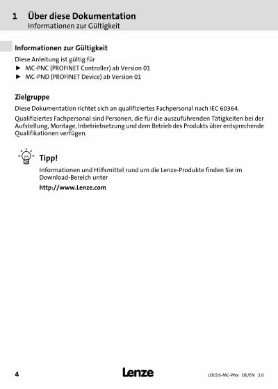
Diese Anleitung ist gültig fürƒ MC−PNC (PROFINET Controller) ab Version 01ƒ MC−PND (PROFINET Device) ab Version 01
Zielgruppe
Diese Dokumentation richtet sich an qualifiziertes Fachpersonal nach IEC 60364.
Qualifiziertes Fachpersonal sind Personen, die für die auszuführenden Tätigkeiten bei derAufstellung, Montage, Inbetriebsetzung und dem Betrieb des Produkts über entsprechendeQualifikationen verfügen.
� Tipp!
Informationen und Hilfsmittel rund um die Lenze−Produkte finden Sie imDownload−Bereich unter
http://www.Lenze.com

Über diese DokumentationDokumenthistorie
1
LDCDS−MC−PNx DE/EN 2.0 5�
DUMMY_NUM_Reset−SIC_UL_de
Dokumenthistorie
Materialnummer Version Beschreibung
13261824 1.0 08/2008 TD29 Erstausgabe
.L^g 2.0 05/2013 TD29 Allgemeine Überarbeitung
Verwendete Konventionen
Informationsart Auszeichnung Beispiele/Hinweise
Zahlenschreibweise
Dezimaltrennzeichen Punkt Es wird generell der Dezimalpunktverwendet.Zum Beispiel: 1234.56
Warnhinweise
UL−Warnhinweise �Werden nur in der englischen Spracheverwendet.UR−Warnhinweise �
Textauszeichnung
Programmname » « PC−SoftwareZum Beispiel: »Engineer«, »GlobalDrive Control« (GDC)
Symbole
Seitenverweis � Verweis auf eine andere Seite mit zu-sätzlichen InformationenZum Beispiel: � 16 = siehe Seite 16
Dokumentationsverweis � Verweis auf eine andere Dokumen-tation mit zusätzlichen Informatio-nenZum Beispiel: � EDKxxx = sieheDokumentation EDKxxx

1 Über diese DokumentationVerwendete Hinweise
LDCDS−MC−PNx DE/EN 2.06 �
DUMMY_NUM_Reset−SIC_UL_de
Verwendete Hinweise
Um auf Gefahren und wichtige Informationen hinzuweisen, werden in dieser Dokumenta-tion folgende Piktogramme und Signalwörter verwendet:
Sicherheitshinweise
Aufbau der Sicherheitshinweise:
� Gefahr!
(kennzeichnet die Art und die Schwere der Gefahr)
Hinweistext
(beschreibt die Gefahr und gibt Hinweise, wie sie vermieden werden kann)
Piktogramm und Signalwort Bedeutung
Gefahr!
Gefahr von Personenschäden durch gefährliche elektri-sche SpannungHinweis auf eine unmittelbar drohende Gefahr, die denTod oder schwere Verletzungen zur Folge haben kann,wenn nicht die entsprechenden Maßnahmen getroffenwerden.
� Gefahr!
Gefahr von Personenschäden durch eine allgemeine Ge-fahrenquelleHinweis auf eine unmittelbar drohende Gefahr, die denTod oder schwere Verletzungen zur Folge haben kann,wenn nicht die entsprechenden Maßnahmen getroffenwerden.
Stop!
Gefahr von SachschädenHinweis auf eine mögliche Gefahr, die Sachschäden zurFolge haben kann, wenn nicht die entsprechenden Maß-nahmen getroffen werden.

Über diese DokumentationVerwendete Hinweise
1
LDCDS−MC−PNx DE/EN 2.0 7�
DUMMY_NUM_Reset−SIC_UL_de
Anwendungshinweise
Piktogramm und Signalwort Bedeutung
� Hinweis! Wichtiger Hinweis für die störungsfreie Funktion
� Tipp! Nützlicher Tipp für die einfache Handhabung
� Verweis auf andere Dokumentation
Spezielle Sicherheitshinweise und Anwendungshinweise für UL und UR
Piktogramm und Signalwort Bedeutung
� Warnings!
Sicherheitshinweis oder Anwendungshinweis für denBetrieb eines UL−approbierten Geräts in UL−approbiertenAnlagen.Möglicherweise wird das Antriebssystem nicht UL−ge-recht betrieben, wenn nicht die entsprechenden Maßnah-men getroffen werden.
� Warnings!
Sicherheitshinweis oder Anwendungshinweis für denBetrieb eines UR−approbierten Geräts in UL−approbiertenAnlagen.Möglicherweise wird das Antriebssystem nicht UL−ge-recht betrieben, wenn nicht die entsprechenden Maßnah-men getroffen werden.

2 Sicherheitshinweise
LDCDS−MC−PNx DE/EN 2.08 �
H1sic_DE−UR−Warn_MC−Card
2 Sicherheitshinweise
� Gefahr!
Wenn Sie die folgenden grundlegenden Sicherheitsmaßnahmen missachten,kann dies zu schweren Personenschäden und Sachschäden führen:
ƒ Lenze−Antriebs− und Automatisierungskomponenten ...... ausschließlich bestimmungsgemäß verwenden.... niemals trotz erkennbarer Schäden in Betrieb nehmen.... niemals technisch verändern.... niemals unvollständig montiert in Betrieb nehmen.... niemals ohne erforderliche Abdeckungen betreiben.... können während und nach dem Betrieb − ihrer Schutzart entsprechend − spannungs-führende, auch bewegliche oder rotierende Teile haben. Oberflächen können heiß sein.
ƒ Alle Vorgaben der beiliegenden und zugehörigen Dokumentation beachten.Dies ist Voraussetzung für einen sicheren und störungsfreien Betrieb sowie für das Er-reichen der angegebenen Produkteigenschaften.Die in diesem Dokument dargestellten verfahrenstechnischen Hinweise und Schal-tungsausschnitte sind Vorschläge, deren Übertragbarkeit auf die jeweilige Anwendungüberprüft werden muss. Für die Eignung der angegebenen Verfahren und Schaltungs-vorschläge übernimmt der Hersteller keine Gewähr.
ƒ Alle Arbeiten mit und an Lenze−Antriebs− und Automatisierungskomponenten darfnur qualifiziertes Fachpersonal ausführen.Nach IEC 60364 bzw. CENELEC HD 384 sind dies Personen, ...... die mit Aufstellung, Montage, Inbetriebsetzung und Betrieb des Produkts vertrautsind.... die über die entsprechenden Qualifikationen für ihre Tätigkeit verfügen.... die alle am Einsatzort geltenden Unfallverhütungsvorschriften, Richtlinien und Ge-setze kennen und anwenden können.
� Warnings!
Use only together with appropriate cable connectors, provided with screws forsecurement and secure connector to avoid loosening.
For use in controlled environment only.

ProduktbeschreibungLieferumfang
3
LDCDS−MC−PNx DE/EN 2.0 9�
−H1−Bestgem Verwend Allg
3 Produktbeschreibung
Lieferumfang
Anzahl Bezeichnung
1 MC−Card
1 Montageanleitung
� Hinweis!
Überprüfen Sie nach Erhalt der Lieferung sofort, ob der Lieferumfang mit denWarenbegleitpapieren übereinstimmt. Für nachträglich reklamierte Mängelübernehmen wir keine Gewährleistung.
Reklamieren Sieƒ erkennbare Transportschäden sofort beim Anlieferer.ƒ erkennbare Mängel / Unvollständigkeit sofort bei der zuständigen
Lenze−Vertretung.
3 ProduktbeschreibungÜbersicht
LDCDS−MC−PNx DE/EN 2.010 �
−H1−Bestgem Verwend Allg
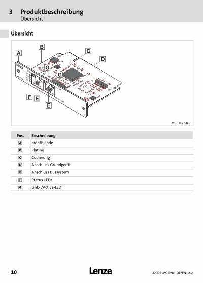
Übersicht
��
�
�
ACTIVE
LINK
PROFIN
ET
MC-PN
x
RJSS-5381
RJSS-5381
SYSST0ST1ST2
���
��
MC−PNx−001
Pos. Beschreibung
� Frontblende
Platine
� Codierung
� Anschluss Grundgerät
� Anschluss Bussystem
� Status−LEDs
� Link− /Active−LED

ProduktbeschreibungÜbersicht
3
LDCDS−MC−PNx DE/EN 2.0 11�
−H1−Bestgem Verwend Allg
LED Farbe Zustand Bedeutung an MC−PNC Bedeutung an MC−PND
SYS grün Ein Betriebssystem läuft
gelb Blinkt mit 1Hz Fehler beim Bootvorgang
Ein Bootloader wartet auf Bootvorgang
− Aus Versorgungsspannung fehlt oder Hardware defekt
ST0 rot Ein Zusammen mit ST1 "rot Ein":keine gültige Master−Lizenz
Systemfehler: Watchdog Timeout; Channel−,
Generische oder ErweiterteDiagnose liegt vor
Blinkt mit 2 Hz Systemfehler:ungültige Konfiguration
DCP−Signal−Service wird überden Bus ausgelöst
− Aus Kein Fehler
ST1 rot Ein Keine Verbindung/kein Link.oder (zusammen mit ST0 "rotEin") keine gültige Master−Li-
zenz
Keine Konfiguation oder lang-same physikalische Verbindung
oder keine physikalische Ver-bindung
Blinkt mit 2 Hz Konfigurationsfehler: Nicht allekonfigurierten IO−Device−Ge-
räte sind verbunden.
Kein Datenaustausch
− Aus Kein Fehler
ST2 − − Ohne Funktion
Link grün Ein Verbindung zum Ethernet besteht
− Aus Verbindung zum Ethernet nicht vorhanden
Active gelb Blinkt Gerät sendet/empfängt Ethernet−Frames

3 ProduktbeschreibungIdentifikation
LDCDS−MC−PNx DE/EN 2.012 �
−H1−Bestgem Verwend Allg
Identifikation
Typenschlüssel MC − PNx − xx
Module Card
PNC = PROFINET ControllerPND = PROFINET Device
Version
Bestimmungsgemäße Verwendung
Die MC−PNC und MC−PND sind Einsteckkarten zur Anbindung eines Lenze−Gerätes an einPROFINET−System.
Während die Device−Anschaltung (MC−PND) dazu dient, das Gerät als Teilnehmer unter ei-ner PROFINET−Steuerung anzusprechen, dient die Controller−Anschaltung (MC−PNC) dazu,selbst eine Steuerung auf Basis von PROFINET herzustellen.
Die MC−Karte wird bestimmungsgemäß verwendet, wenn sie ausschließlich in Lenze−Ge-räte mit MC−Card−Schnittstelle eingesetzt wird. Eine andere oder darüber hinaus gehendeVerwendung ist nicht zulässig. Weitere Informationen finden Sie im Systemhandbuch IPCund im Systemhandbuch Visiualisierung.
Technische DatenAllgemeine Daten
4
LDCDS−MC−PNx DE/EN 2.0 13�
H1_Daten−E−Daten MC−PND
4 Technische Daten
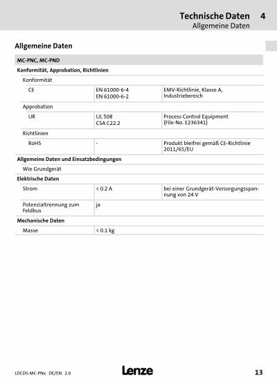
Allgemeine Daten
MC−PNC, MC−PND
Konformität, Approbation, Richtlinien
Konformität
CE EN 61000−6−4EN 61000−6−2
EMV−Richtlinie, Klasse A, Industriebereich
Approbation
UR UL 508CSA C22.2
Process Control Equipment (File−No. E236341)
Richtlinien
RoHS − Produkt bleifrei gemäß CE−Richtlinie2011/65/EU
Allgemeine Daten und Einsatzbedingungen
Wie Grundgerät
Elektrische Daten
Strom < 0.2 A bei einer Grundgerät−Versorgungsspan-nung von 24 V
Potenzialtrennung zumFeldbus
ja
Mechanische Daten
Masse < 0.1 kg
4 Technische DatenKommunikationsdaten
LDCDS−MC−PNx DE/EN 2.014 �
H1_Daten−E−Daten MC−PND
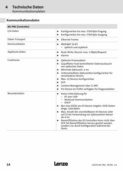
Kommunikationsdaten
MC−PNC (Controller)
E/A−Daten � Konfigurierbar bis max. 5760 Byte Eingang
� Konfigurierbar bis max. 5760 Byte Ausgang
Daten−Transport � Ethernet Frames
Kommunikation � PROFINET IO−RT– zyklisch und azyklisch
Azyklische Daten � Read, Write, Record: max. 1 KByte/Request
� Alarme
Funktionen � Zyklische Prozessdaten
� Gepufferter host−kontrollierter Datenaustauschvon zyklischen Daten
� Minimale Zykluszeit: 1 ms
� Unterschiedliche Zykluszeiten konfigurierbar fürverschiedene Devices
� Max. 32 Devices konfigurierbar
� DCP
� Context−Management über CL−RPC
� Pro Device ein Puffer verfügbar für Diagnosedaten
Besonderheiten � Keine Unterstützung für– RT over UDP– Multicast−Kommunikation– DHCP
� Nur eine IOCR1 pro IO−Device möglich, IOCR−Daten-länge: 1024 Bytes
� Max. Anzahl der anschließbaren IO−Devices sinktauf 25 bei Verwendung von Zykluszeitren kleinerals 4 ms
� NameOfStation des IO−Controllers kann nicht überDCP Set NameOfStation−Service gesetzt werden,sondern nur durch Konfiguration während desStarts

Technische DatenKommunikationsdaten
4
LDCDS−MC−PNx DE/EN 2.0 15�
H1_Daten−E−Daten MC−PND
MC−PND (Device)
E/A−Daten � Konfigurierbar bis max 1024 Byte Eingang
� Konfigurierbar bis max 1024 Byte Ausgang
Kommunikation � PROFINET IO−RT– VLAN− und Priority−Tagging– zyklisch und azyklisch
Funktionen � zyklische Prozessdaten
� azyclische Lese− und Schreibabfragen
� Prozess− und Diagnosealarm: 200 Byte
� DCP
� Context Management über CLRPC
� Generische Diagnose, Channel−Diagnose, Erwei-terte Channel−Diagnose: 200 Byte
� Soll−/Ist−Vergleich der Konfiguration
Besonderheiten � Maximale Anzahl Module: 244
� Maximale Anzahl Submodule: 1
� Keine Unterstützung für– RT over UDP– Multicast−Kommunikation
� Es wird nur eine Geräteinstanz unterstützt

5 Elektrische Installation
LDCDS−MC−PNx DE/EN 2.016 �
H1_E_INST−Hin_Auto−Crossover
5 Elektrische Installation
Wichtige Hinweise
Stop!
Kurzschluss und statische Entladungen
Die Flachbaugruppe enthält Bauelemente, die bei Kurzschluss oder statischerEntladung gefährdet sind.
Mögliche Folgen:ƒ Die Flachbaugruppe oder angeschlossene Geräte werden zerstört.
Schutzmaßnahmen:ƒ Bei allen Arbeiten an der Flachbaugruppe muss diese spannungsfrei sein.
Dies gilt insbesondere vor dem Stecken/Ziehen der Baugruppe und demAnschließen/Abziehen von Steckverbindern.
ƒ Alle Personen, die Flachbaugruppen handhaben, müssen ESD−Maßnahmenberücksichtigen.
ƒ Kontakte von Steckverbindern dürfen nicht berührt werden.ƒ Flachbaugruppen dürfen nur an kontaktfreien Stellen angefasst werden
und nur auf geeigneten Unterlagen abgelegt werden (z. B. aufESD−Verpackung oder leitfähigem Schaumstoff).
ƒ Flachbaugruppen dürfen nur in ESD−Verpackungen transportiert undgelagert werden.
� Hinweis!
Zum Einbau der Baugruppe muss das Gehäuse des Industrie−PCs geöffnetwerden (� Dokumentation zum Grundgerät).

Elektrische Installation 5
LDCDS−MC−PNx DE/EN 2.0 17�
H1_E_INST−Hin_Auto−Crossover
Montage
SPEED
MC-ETH
RJSS-5381
RJSS-5381
SPEED
LINK
LAN
MC-ETH
RJSS-5381
RJSS-5381
� �
�
ACTIVE
LINK
PROFIN
ET
MC-PN
x
RJSS-5381
RJSS-5381
RJSS-5381
RJSS-5381
SYSST0ST1ST2
LINK
LAN
ACTIVE
LINK
PROFIN
ET
MC-PN
x
RJSS-5381
RJSS-5381
RJSS-5381
RJSS-5381
SYSST0ST1ST2
MC−PNx−002

5 Elektrische Installation
LDCDS−MC−PNx DE/EN 2.018 �
H1_E_INST−Hin_Auto−Crossover
Verdrahtung
Beschreibung Anschlusstyp Kabeltyp
1 8
Anschluss EthernetPin 1: TX+Pin 2: TX−Pin 3: RX+Pin 4: Term1*Pin 5: Term1*Pin 6: RX−Pin 7: Term2**Pin 8: Term2**
RJ45−Buchse
Netzwerkkabel CAT5S/UTP oder CAT5e
S/FTP (empfohlen), Ka-bellänge max. 100 m
MC−PNx−003
* Gebrückt und zu PE über RC−Glied terminiert** Gebrückt und zu PE über RC−Glied terminiert
� Hinweis!
Das Gerät unterstützt die Auto−Crossover−Funktion, wodurch RX und TXgegebenenfalls gegeneinander getauscht sein können.

KonfigurationWindows XP
6
LDCDS−MC−PNx DE/EN 2.0 19�
H1_konfig−Einsatz_MC_PBx_CE_Hin
6 Konfiguration
Windows XP
Um die Kommunikationskarte unter Windows� XP nutzen zu können, ist ein Gerätetreibererforderlich.
Der Gerätetreiber übernimmt die komplette Verwaltung der Schnittstelle und beinhalteteine einfache C−Schnittstelle, die über eine DLL angesprochen wird. Der Anwender ist nurfür die Übergabe der richtigen Parameter an den Device−Treiber zuständig. Alle Abhängig-keiten vom Betriebssystem wie Interruptverwaltung und Zeitüberwachung werden durchden Treiber realisiert.
Der Treiber umfasst alle Funktionen zum Initialisieren, Parametrieren, Austauschen von Da-ten und Auslesen von Statusinformationen. Er arbeitet im Polling− oder Interrupt−Modusund bedient maximal zwei Karten in einen IPC.
Zusammen mit dem Gerätetreiber werden Beispielprogramm im Quellcode geliefert, dieeine rasche Einarbeitung erlauben. Weiterer Bestandteil ist ein Installationsprogramm zurRegistrierung beim Betriebssystem, sowie der Buskonfigurator SyCon.net zur Konfigura-tion des Masters.
� Hinweis!
Die Kommunikationskarte basiert auf der netX−Technologie der Firma Hilscher.Bei der Firma Hilscher erhalten Sie weitere Informationen zurProgrammier−Schnittstelle sowie Programmierbeispiele zum CIF Device Driver.
Es dürfen ausschließlich die von Lenze freigegebenen Treiber verwendetwerden.
Das Ansprechen der Kommunikationskarte aus eigenen Anwendungen herauserfordert spezielle Programmierkenntnisse. Lenze kann Sie nur bei dergrundsätzlichen Inbetriebnahme der Karte unterstützen. Bei speziellen Fragenzur Programmierung, steht nach Rücksprache mit Lenze der Support der FirmaHilscher zur Verfügung. Dort können auch kostenpflichtige Dienstleistungen inAuftrag gegeben werden.
In der Regel ist die Kommunikationskarte im IPC bereits montiert und der Treiber ist instal-liert und konfiguriert. Die folgenden Schritte sind daher nur notwendig, wenn die Kommu-nikationskarte separat bestellt wurde oder das System neu aufgesetzt werden soll.
Den "cifX Device Driver" und die zugehörige Dokumentation finden Sie auf der DVD "PCbased Automation" oder im Internet unter www.Lenze.com im Bereich "Services & Downlo-ads".

6 KonfigurationWindows XP
LDCDS−MC−PNx DE/EN 2.020 �
H1_konfig−Einsatz_MC_PBx_CE_Hin
� So gehen Sie bei der Installation des Gerätetreibers vor:1. Schalten Sie nach der Montage der Kommunikationskarte den IPC ein.
Das Betriebssystem erkennt die neue Hardware und der "Assistent für das Suchen neuerHardware" startet.
2. Wählen Sie Software von einer Liste oder bestimmten Quelle installieren.3. Legen Sie die DVD "PC based Automation" in das DVD−Laufwerk ein und klicken Sie
auf Weiter.4. Markieren Sie im folgenden Dialog das Optionsfeld Diese Quelle nach dem
zutreffenden Treiber durchsuchen und das Kontrollfeld Wechselmedien durchsuchen(Diskette, CD,..).
5. Klicken Sie auf Weiter.Der CifX−Treiber wird installiert. Der Installationsfortschritt wird angezeigt. Abschlie-ßend meldet der Assistent, dass die Software für das "cifX PCI/PCIe Device" installiertwurde.
6. Klicken Sie auf Fertigstellen.7. Prüfen Sie, ob die Kommunikationskarte korrekt installiert ist:
– Starten Sie die Windows�−Systemsteuerung.– Wenn Sie die "klassische Ansicht" eingestellt haben, klicken Sie dort doppelt auf
den Eintrag System. Wenn Sie die "Kategorieansicht" eingestellt haben, wählenSie Leistung und Wartung � System.
– Wählen Sie im Dialog "Systemeigenschaften" das Register Hardware.Der Geräte−Manger wird geöffnet. Wenn dort unter "CIFx Communication Interface" �"CifX PCI/PCIe Device" kein Fehler gemeldet wird, ist die Kommunikationskarte ord-nungsgemäß installiert.
KonfigurationWindows XP
6
LDCDS−MC−PNx DE/EN 2.0 21�
H1_konfig−Einsatz_MC_PBx_CE_Hin
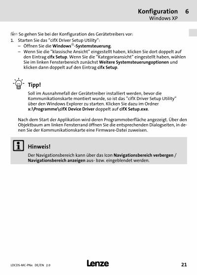
� So gehen Sie bei der Konfiguration des Gerätetreibers vor:1. Starten Sie das "cifX Driver Setup Utility":
– Öffnen Sie die Windows�−Systemsteuerung.– Wenn Sie die "klassische Ansicht" eingestellt haben, klicken Sie dort doppelt auf
den Eintrag cifx Setup. Wenn Sie die "Kategorieansicht" eingestellt haben, wählenSie im linken Fensterbereich zunächst Weitere Systemsteuerungoptionen undklicken dann doppelt auf den Eintrag cifx Setup.
� Tipp!
Soll im Ausnahmefall der Gerätetreiber installiert werden, bevor dieKommunikationskarte montiert wurde, so ist das "cifX Driver Setup Utility"über den Windows Explorer zu starten. Klicken Sie dazu im Ordnerx:\Programme\cifX Device Driver doppelt auf cifX Setup.exe.
Nach dem Start der Applikation wird deren Programmoberfläche angezeigt. Über denObjektbaum am linken Fensterrand öffnen Sie die entsprechenden Dialogseiten, in de-nen Sie der Kommunikationskarte eine Firmware−Datei zuweisen.
� Hinweis!
Der Navigationsbereich kann über das Icon Navigationsbereich verbergen /Navigationsbereich anzeigen aus− bzw. eingeblendet werden.

6 KonfigurationWindows XP
LDCDS−MC−PNx DE/EN 2.022 �
H1_konfig−Einsatz_MC_PBx_CE_Hin
2. Weisen Sie dem Kommunikationskanal 0 (CH#0) die busspezifische Firmware−Dateizu:– Öffnen Sie im Objektbaum den Ordner Active Devices und den (Unter−)Ordner der
Kommunikationskarte (z. B. cifX0 ( )), die Sie konfigurieren möchten.– Klicken Sie dort auf den Kommunikationskanal, dem Sie eine Firmware−Datei
zuweisen möchten. Die zugehörige Dialogseite wird angezeigt.– Klicken Sie im Bereich Downloads (Modules) auf die Schaltfläche Add und wählen
Sie im nachfolgenden Auswahlmenü die Firmware−Datei (*.nxf).– Bestätigen Sie die Auswahl mit OK. Der Speicherpfad und der Name der
Firmware−Datei wird in der Liste "File" angezeigt.– Betätigen Sie die Schaltfläche Apply.
3. Beenden Sie die Applikation "cifX Driver Setup Utility" über das Menü File � Quit.
� Hinweis!
Nur bei MC−PNC (Controller):ƒ Konfigurieren Sie den Bus über die Host−Applikation bzw. den
Buskonfigurator "SyCon.net".
Nur bei MC−PND (Device):ƒ Konfigurieren Sie den Bus über die Warmstartparameter in der "cifX Driver
Setup Utility". Weitere Informationen finden Sie in der Online−Hilfe des"cifX Driver Setup Utility" sowie in der Dokumentation der Firma Hilscher.

KonfigurationWindows CE
6
LDCDS−MC−PNx DE/EN 2.0 23�
H1_konfig−Einsatz_MC_PBx_CE_Hin
Windows CE
� Hinweis!
Für die Nutzung der Kommunikationskarte in eigenen Anwendungen wird zurZeit keine spezielle Unterstützung angeboten. Projektspezifisch ist jedoch eineOffenlegung möglich. Bitte wenden Sie sich an Ihre zuständigeVertriebszentrale.

6 KonfigurationWindows CE
LDCDS−MC−PNx DE/EN 2.024 �
H1_konfig−Einsatz_MC_PBx_CE_Hin
Contents i
LDCDS−MC−PNx DE/EN 2.0 25�
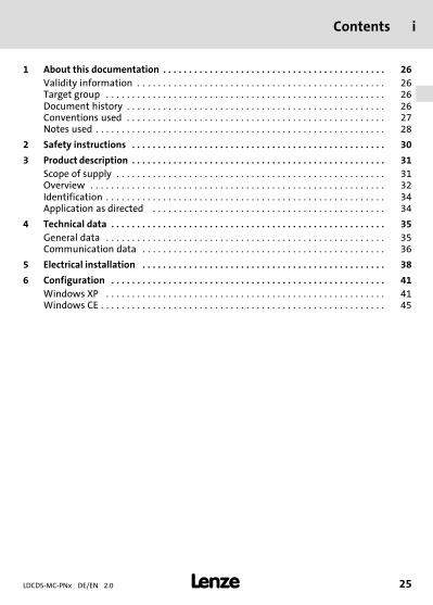
Inhalt
1 About this documentation 26. . . . . . . . . . . . . . . . . . . . . . . . . . . . . . . . . . . . . . . . . . . Validity information 26. . . . . . . . . . . . . . . . . . . . . . . . . . . . . . . . . . . . . . . . . . . . . . . . Target group 26. . . . . . . . . . . . . . . . . . . . . . . . . . . . . . . . . . . . . . . . . . . . . . . . . . . . . . Document history 26. . . . . . . . . . . . . . . . . . . . . . . . . . . . . . . . . . . . . . . . . . . . . . . . . . Conventions used 27. . . . . . . . . . . . . . . . . . . . . . . . . . . . . . . . . . . . . . . . . . . . . . . . . . Notes used 28. . . . . . . . . . . . . . . . . . . . . . . . . . . . . . . . . . . . . . . . . . . . . . . . . . . . . . . .
2 Safety instructions 30. . . . . . . . . . . . . . . . . . . . . . . . . . . . . . . . . . . . . . . . . . . . . . . . .
3 Product description 31. . . . . . . . . . . . . . . . . . . . . . . . . . . . . . . . . . . . . . . . . . . . . . . . . Scope of supply 31. . . . . . . . . . . . . . . . . . . . . . . . . . . . . . . . . . . . . . . . . . . . . . . . . . . . Overview 32. . . . . . . . . . . . . . . . . . . . . . . . . . . . . . . . . . . . . . . . . . . . . . . . . . . . . . . . . Identification 34. . . . . . . . . . . . . . . . . . . . . . . . . . . . . . . . . . . . . . . . . . . . . . . . . . . . . . Application as directed 34. . . . . . . . . . . . . . . . . . . . . . . . . . . . . . . . . . . . . . . . . . . . .
4 Technical data 35. . . . . . . . . . . . . . . . . . . . . . . . . . . . . . . . . . . . . . . . . . . . . . . . . . . . . General data 35. . . . . . . . . . . . . . . . . . . . . . . . . . . . . . . . . . . . . . . . . . . . . . . . . . . . . . Communication data 36. . . . . . . . . . . . . . . . . . . . . . . . . . . . . . . . . . . . . . . . . . . . . . .
5 Electrical installation 38. . . . . . . . . . . . . . . . . . . . . . . . . . . . . . . . . . . . . . . . . . . . . . .
6 Configuration 41. . . . . . . . . . . . . . . . . . . . . . . . . . . . . . . . . . . . . . . . . . . . . . . . . . . . . Windows XP 41. . . . . . . . . . . . . . . . . . . . . . . . . . . . . . . . . . . . . . . . . . . . . . . . . . . . . . Windows CE 45. . . . . . . . . . . . . . . . . . . . . . . . . . . . . . . . . . . . . . . . . . . . . . . . . . . . . . .

1 About this documentationValidity information
LDCDS−MC−PNx DE/EN 2.026 �
DUMMY_NUM_Reset−SIC_UL_en
0Fig. 0Tab. 01 About this documentation
Validity information
These instructions are valid forƒ MC−PNC (PROFINET controller ) as of version 01ƒ MC−PND (PROFINET device) as of version 01
Target group
This documentation is directed at qualified skilled personnel according to IEC 60364.
Qualified skilled personnel are persons who have the required qualifications to carry out allactivities involved in installing, mounting, commissioning, and operating the product.
� Tip!
Information and auxiliary devices related to the Lenze products can be foundin the download area at
http://www.Lenze.com
Document history
Material number Version Description
13261824 1.0 08/2008 TD29 First edition
.L^g 2.0 05/2013 TD29 General revision
About this documentationConventions used
1
LDCDS−MC−PNx DE/EN 2.0 27�
DUMMY_NUM_Reset−SIC_UL_en
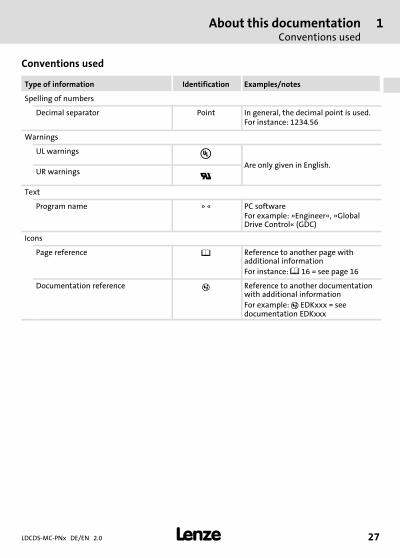
Conventions used
Type of information Identification Examples/notes
Spelling of numbers
Decimal separator Point In general, the decimal point is used.For instance: 1234.56
Warnings
UL warnings �Are only given in English.
UR warnings �Text
Program name » « PC softwareFor example: »Engineer«, »GlobalDrive Control« (GDC)
Icons
Page reference � Reference to another page withadditional informationFor instance: � 16 = see page 16
Documentation reference � Reference to another documentationwith additional informationFor example: � EDKxxx = seedocumentation EDKxxx

1 About this documentationNotes used
LDCDS−MC−PNx DE/EN 2.028 �
DUMMY_NUM_Reset−SIC_UL_en
Notes used
The following pictographs and signal words are used in this documentation to indicatedangers and important information:
Safety instructions
Structure of safety instructions:
� Danger!
(characterises the type and severity of danger)
Note
(describes the danger and gives information about how to prevent dangeroussituations)
Pictograph and signal word Meaning
Danger!
Danger of personal injury through dangerous electricalvoltage.Reference to an imminent danger that may result indeath or serious personal injury if the correspondingmeasures are not taken.
� Danger!
Danger of personal injury through a general source ofdanger.Reference to an imminent danger that may result indeath or serious personal injury if the correspondingmeasures are not taken.
Stop!
Danger of property damage.Reference to a possible danger that may result inproperty damage if the corresponding measures are nottaken.
About this documentationNotes used
1
LDCDS−MC−PNx DE/EN 2.0 29�
DUMMY_NUM_Reset−SIC_UL_en
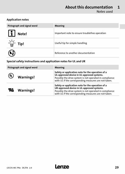
Application notes
Pictograph and signal word Meaning
� Note! Important note to ensure troublefree operation
� Tip! Useful tip for simple handling
� Reference to another documentation
Special safety instructions and application notes for UL and UR
Pictograph and signal word Meaning
� Warnings!
Safety or application note for the operation of aUL−approved device in UL−approved systems.Possibly the drive system is not operated in compliancewith UL if the corresponding measures are not taken.
� Warnings!
Safety or application note for the operation of aUR−approved device in UL−approved systems.Possibly the drive system is not operated in compliancewith UL if the corresponding measures are not taken.

2 Safety instructions
LDCDS−MC−PNx DE/EN 2.030 �
H1sic_EN−UR−Warn_MC−Card
2 Safety instructions
� Danger!
Disregarding the following basic safety measures may lead to severe personalinjury and damage to material assets!
ƒ Lenze drive and automation components ...... must only be used for the intended purpose.... must never be operated if damaged.... must never be subjected to technical modifications.... must never be operated unless completely assembled.... must never be operated without the covers/guards.... can − depending on their degree of protection − have live, movable or rotating partsduring or after operation. Surfaces can be hot.
ƒ All specifications of the corresponding enclosed documentation must be observed.This is vital for a safe and trouble−free operation and for achieving the specified productfeatures.The procedural notes and circuit details provided in this document are proposals whichthe user must check for suitability for his application. The manufacturer does not acceptany liability for the suitability of the specified procedures and circuit proposals.
ƒ Only qualified skilled personnel are permitted to work with or on Lenze drive andautomation components.According to IEC 60364 or CENELEC HD 384, these are persons ...... who are familiar with the installation, assembly, commissioning and operation of theproduct,... possess the appropriate qualifications for their work,... and are acquainted with and can apply all the accident prevent regulations, directivesand laws applicable at the place of use.
� Warnings!
Use only together with appropriate cable connectors, provided with screws forsecurement and secure connector to avoid loosening.
For use in controlled environment only.

Product descriptionScope of supply
3
LDCDS−MC−PNx DE/EN 2.0 31�
−H1−Bestgem Verwend Allg
3 Product description
Scope of supply
Number Name
1 MC card
1 Mounting Instructions
� Note!
After receipt of the delivery, check immediately whether the items match theaccompanying papers. We do not accept any liability for deficiencies claimedsubsequently.
Claimƒ visible transport damage immediately to the forwarderƒ visible deficiencies/incompleteness immediately to your Lenze
representative.

3 Product descriptionOverview
LDCDS−MC−PNx DE/EN 2.032 �
−H1−Bestgem Verwend Allg
Overview
��
�
�
ACTIVE
LINK
PROFIN
ET
MC-PN
x
RJSS-5381
RJSS-5381
SYSST0ST1ST2
���
��
MC−PNx−001
Pos. Description
� Front panel
Printed circuit board
� Coding
� Standard device connection
� Bus system connection
� Status LEDs
� Link /Active LED

Product descriptionOverview
3
LDCDS−MC−PNx DE/EN 2.0 33�
−H1−Bestgem Verwend Allg
LED Colour
Status Meaning at MC−PNC Meaning at MC−PND
SYS Green On Operating system is running
Yellow
Blinking with1Hz
Error during boot process
On Boot loader waits for boot process
− Off No supply voltage or defect hardware
ST0 Red On Together with ST1 "Red On":no valid master licence
System error: Watchdog time−out; channel,
generic or extendeddiagnostics is available
Blinking with2 Hz
System error:invalid configuration
DCP signal service is enabledvia the bus
− Off No error
ST1 Red On No connection/no link. Or(together with ST0 "Red On")
no valid master licence
No configuration or slowphysical connection or no
physical connection
Blinking with2 Hz
Configuration error: Not allconfigured I/O devices are
connected.
No data exchange
− Off No error
ST2 − − No function
Link Green On Connection to Ethernet exists
− Off No connection to Ethernet
Active Yellow
Blinking Device transmits/receives Ethernet frames
3 Product descriptionIdentification
LDCDS−MC−PNx DE/EN 2.034 �
−H1−Bestgem Verwend Allg
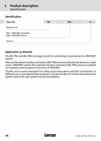
Identification
Type code MC − PNx − xx
Module Card
PNC = PROFINET ControllerPND = PROFINET Device
Version
Application as directed
The MC−PNC and MC−PND are plug−in cards for connecting a Lenze device to a PROFINETsystem.
Whereas the device interface connection (MC−PND) serves to activate the device as a nodeunder a PROFINET control, the controller interface connection (MC−PNC) serves to establishan individual control system on the basis of PROFINET.
The MC card is used as directed if it is solely used in lenze device with MC card interface. Adifferent use, or one beyond these purposes, is not permissible. For further informations seesystem manual IPC oder system manual Visualisation.

Technical dataGeneral data
4
LDCDS−MC−PNx DE/EN 2.0 35�
H1_Daten−E−Daten MC−PND
4 Technical data
General data
MC−PNC, MC−PND
Conformity, approval, directive
Conformity
CE EN 61000−6−4EN 61000−6−2
EMC Directive Class A,industrial premises
Approval
UR UL 508CSA C22.2
Process Control Equipment (File−No. E236341)
Directive
RoHS − Products lead−free in accordance withCE Directive 2011/65/EU
General data and operating conditions
See standard device
Electrical data
Current < 0.2 A at standard device supply voltage of24 V
Electrical isolation to thefieldbus
yes
Mechanical data
Mass < 0.1 kg

4 Technical dataCommunication data
LDCDS−MC−PNx DE/EN 2.036 �
H1_Daten−E−Daten MC−PND
Communication data
MC−PNC (controller)
I/O data � Configurable up to max. 5760 bytes input
� Configurable up to max. 5760 bytes output
Data transport � Ethernet frames
Communication � PROFINET IO−RT– cyclic and acyclic
Acyclic data � Read, write, record: max. 1 kbyte/request
� Alarms
Functions � Cyclic process data
� Buffering host−controlled data exchange of cyclicdata
� Minimum cycle time: 1 ms
� Different cycle times are configurable for differentdevices
� Max. 32 devices can be configured
� DCP
� Context management via CL−RPC
� One buffer is available per device for diagnosticdata
Special features � No support for– RT over UDP– Multicast communication– DHCP
� Only one IOCR1 per IO device is possible, IOCR datalength: 1024 bytes
� Max. number of the connectable IO devicesdecreases to 25 when cycle times lower than 4 msare used.
� NameOfStation of the IO controller cannot be setvia the DCP Set NameOfStation service but only bythe configuration during the start
Technical dataCommunication data
4
LDCDS−MC−PNx DE/EN 2.0 37�
H1_Daten−E−Daten MC−PND
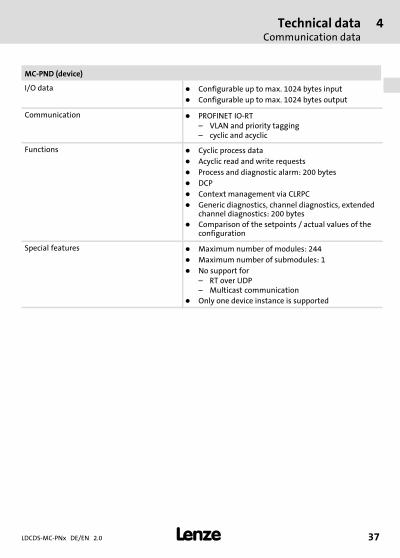
MC−PND (device)
I/O data � Configurable up to max. 1024 bytes input
� Configurable up to max. 1024 bytes output
Communication � PROFINET IO−RT– VLAN and priority tagging– cyclic and acyclic
Functions � Cyclic process data
� Acyclic read and write requests
� Process and diagnostic alarm: 200 bytes
� DCP
� Context management via CLRPC
� Generic diagnostics, channel diagnostics, extendedchannel diagnostics: 200 bytes
� Comparison of the setpoints / actual values of theconfiguration
Special features � Maximum number of modules: 244
� Maximum number of submodules: 1
� No support for– RT over UDP– Multicast communication
� Only one device instance is supported
5 Electrical installation
LDCDS−MC−PNx DE/EN 2.038 �
H1_E_INST−Hin_Auto−Crossover
5 Electrical installation
Important notes
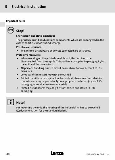
Stop!
Short circuit and static discharges
The printed circuit board contains components which are endangered in thecase of short circuit or static discharge.
Possible consequences:ƒ The printed circuit board or devices connected are destroyed.
Protective measures:ƒ When working on the printed circuit board, the unit has to be
disconnected from the supply. This particularly applies to plugging in/outthe unit and the connectors.
ƒ All persons handling printed circuit boards have to take account of ESDmeasures.
ƒ Contacts of connectors may not be touched.ƒ Printed circuit boards may be touched only at places free from electrical
contacts and may be placed only on appropriate materials (e.g. on ESDpackaging or conductive foam material).
ƒ Printed circuit boards may only be transported and stored in ESDpackaging.
� Note!
For mounting the unit, the housing of the industrial PC has to be opened(� documentation for the standard device).
Electrical installation 5
LDCDS−MC−PNx DE/EN 2.0 39�
H1_E_INST−Hin_Auto−Crossover
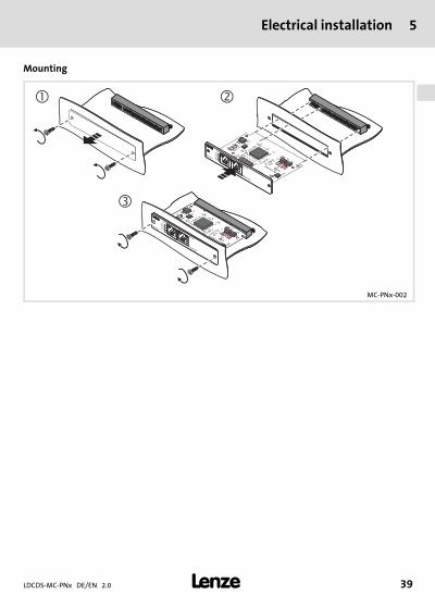
Mounting
SPEED
MC-ETH
RJSS-5381
RJSS-5381
SPEED
LINK
LAN
MC-ETH
RJSS-5381
RJSS-5381
� �
�
ACTIVE
LINK
PROFIN
ET
MC-PN
x
RJSS-5381
RJSS-5381
RJSS-5381
RJSS-5381
SYSST0ST1ST2
LINK
LAN
ACTIVE
LINK
PROFIN
ET
MC-PN
x
RJSS-5381
RJSS-5381
RJSS-5381
RJSS-5381
SYSST0ST1ST2
MC−PNx−002

5 Electrical installation
LDCDS−MC−PNx DE/EN 2.040 �
H1_E_INST−Hin_Auto−Crossover
Wiring
Description Connection type Cable type
1 8
Ethernet connectionPin 1: TX+Pin 2: TX−Pin 3: RX+Pin 4: Term1*Pin 5: Term1*Pin 6: RX−Pin 7: Term2**Pin 8: Term2**
RJ45 socket
Network cable CAT5S/UTP or CAT5e S/FTP(recommended), cable
length max. 100 m
MC−PNx−003
* Bridged and terminated by RC circuit against PE** Bridged and terminated by RC circuit against PE
� Note!
The device supports the auto−crossover function where RX and TX can beexchanged, if required.

ConfigurationWindows XP
6
LDCDS−MC−PNx DE/EN 2.0 41�
H1_konfig−Einsatz_MC_PBx_CE_Hin
6 Configuration
Windows XP
In order to use the communication card in Windows� XP, a device driver is required.
The device driver assumes the entire management of the interface and contains a simpleC interface which is addressed via a DLL. The user is only responsible for the transfer of thecorrect parameters to the device driver. All dependencies on the operating system likeinterrupt management and time monitoring are executed by the driver.
The driver comprises all functions for initialising, parameter setting, exchanging data, andreading out status information. It operates in the polling or interrupt mode and controlsmaximally two cards in an IPC.
Together with the device drivers, example programs are supplied in the source code for aquick training. Other components are an installation program for registration at theoperating system and the SyCon.net bus configurator of the master.
� Note!
The communication card is based on the netX technology of the Hilschercompany. Further information on the programming interface andprogramming examples for the CIF Device Driver can be obtained from theHilscher company.
Only drivers approved by Lenze may be used.
Addressing the communication card from your own applications requiresspecial programming skills. Lenze can only assist you in the basiccommissioning of the card. If you have special questions about programming,the Hilscher company will help you after contacting Lenze. There, alsochargeable services can be ordered.
Usually, the communication card in the IPC is already mounted and the driver is installedand configured. Thus, the following steps are only required if the communication card hasbeen ordered separately or the system is to be set up anew.
The "cifX Device Driver" and the corresponding documentation can be found on the "PCbased Automation" DVD or on the Internet at www.Lenze.com in the download area.

6 ConfigurationWindows XP
LDCDS−MC−PNx DE/EN 2.042 �
H1_konfig−Einsatz_MC_PBx_CE_Hin
� How to install the device driver:1. Switch on the IPC after installing the communication card.
The operating system recognises the new hardware and the "Found New HardwareWizard" starts.
2. Select Install from a list or specific location.3. Insert the "PC based Automation" DVD into the DVD drive and click Next.4. Select the Search the best driver in these locations option field and the Search
exchangeable disk storage (floppy disk, CD,..) control field in the following dialog.5. Click Next.
The CifX driver is installed. The installation progress is displayed. At the end, the wizardreports that the software for the "cifX PCI/PCIe Device" has been installed.
6. Click Complete.7. Check if the communication card has been installed correctly:
– Start the Windows� system control.– If you have set the "classic view", double−click the System entry. If you have set the
"category view", select Performance and Maintenance � System.– Select the Hardware register from the "System properties" dialog.The device manager is opened. If no error is reported under "CIFx CommunicationInterface" � "CifX PCI/PCIe Device", the communication card has been installedcorrectly.
ConfigurationWindows XP
6
LDCDS−MC−PNx DE/EN 2.0 43�
H1_konfig−Einsatz_MC_PBx_CE_Hin
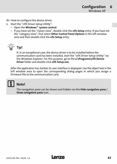
� How to configure the device driver:1. Start the "cifX Driver Setup Utility":
– Open the Windows� system control.– If you have set the "classic view", double−click the cifx Setup entry. If you have set
the "category view", first select Other Control Panel Options in the left windowarea and then double−click the cifx Setup entry.
� Tip!
If, in an exceptional case, the device driver is to be installed before thecommunication card has been installed, start the "cifX Driver Setup Utility" viathe Windows Explorer. For this purpose, go to the x:\Programs\cifX DeviceDriver folder and double−click cifX Setup.exe.
After the application has started, its user interface is displayed. Use the object tree in theleft window area to open the corresponding dialog pages in which you assign afirmware file to the communication card.
� Note!
The navigation pane can be shown and hidden via the Hide navigation pane /Show navigation pane icon.

6 ConfigurationWindows XP
LDCDS−MC−PNx DE/EN 2.044 �
H1_konfig−Einsatz_MC_PBx_CE_Hin
2. Assign the bus−specific firmware file to the communication channel 0 (CH#0):– Go to the object tree and open the Active Devices folder and the (sub) folder of the
communication card (e.g. cifX0 ( )) you want to configure.– Click the communication channel you want to assign to a firmware file. The
respective dialog page is displayed.– Go to the Downloads (Modules) area, click the Add button and select the firmware
file (*.nxf) in the following menu.– Confirm the selection with OK. The file path and the name of the firmware file are
displayed in the "File" list.– Click the Apply button.
3. Exit the "cifX Driver Setup Utility" application via the File � Quit menu.
� Note!
Only for MC−PNC (Controller):ƒ Configure the bus via the host application or the bus configurator
"SyCon.net".
Only for MC−PND (Device):ƒ Configure the bus via the warm start parameters in the "cifX Driver Setup
Utility". Further information can be obtained from the online help of the"cifX Driver Setup Utility" and the documentation of Hilscher.

ConfigurationWindows CE
6
LDCDS−MC−PNx DE/EN 2.0 45�
H1_konfig−Einsatz_MC_PBx_CE_Hin
Windows CE
� Note!
No special support is provided currently if you use the communication card inyour own applications. For special projects, please contact your sales office.

backside
� �© 05/2013
� Lenze Automation GmbHHans−Lenze−Str. 1D−31855 AerzenGermany
Service Lenze Service GmbHBreslauer Straße 3D−32699 ExtertalGermany
� +49�(0)51 54 /�82−0 � 00�80�00�/ 24�4�68�77 (24 h helpline)
� +49�(0)51 54 /�82 − 28 00 � +49�(0)51�54�/ 82−11 12
� [email protected] � [email protected]
� www.Lenze.com
LDCDS−MC−PNx � .L^g � DE/EN � 2.0 � TD29
10 9 8 7 6 5 4 3 2 1