Mounting Accessories, Working hard behind the scene ... · MOUNTING ACCESSORIES - Working Hard...
89
technical data clipsal.com beh ind the scene technical data clipsal.com
Transcript of Mounting Accessories, Working hard behind the scene ... · MOUNTING ACCESSORIES - Working Hard...

The shape of the switch dolly is a trade mark of Clipsal Australia Pty. Ltd.
tech
nica
l da
ta
clipsal.com
behindthe
scene
Workinghard
tech
nica
l da
ta
WorkingM
OU
NT
ING
AC
CE
SS
OR
IES
- W
ork
ing
Har
d B
ehin
d T
he
Sce
ne
O/N
893
026
A
ug
ust
06/
02
Special thanks to Graham Ward (Active Connection Electrical) and Greg Spurling (Spurling Electrical) for their contribution to this catalogue.
clipsal.com
Clipsal Australia Pty Ltd reserves the right to change specifi cations, modify designs and dis con tin ue items without incurring obligation and whilst every effort is made to ensure that descriptions, specifi cations and other in for ma tion in this catalogue are correct, no warranty is given in respect thereof and the company shall not be liable for any error therein.
Product of Clipsal Australia Pty LtdABN 27 007 873 529
Head Offi ce12 Park Terrace, Bowden South Australia 5007Telephone (08) 8269 0511Facsimile (08) 8340 1724Internet clipsal.comE-Mail [email protected]
National Customer Service Enquiries:1300 2025 25National Customer Service Facsimile:1300 2025 56Area RepresentativesNSW Albury (02) 6051 2377 Central 0418 430 361 Coffs Harbour 0418 653 183 Dubbo 0418 822 564 Newcastle 0407 298 792 0418 434 169 0418 686 040 Tamworth 0417 714 339 Wagga Wagga 0418 578 903 Wollongong 0418 423 581
ACT Canberra 0419 238 824 0418 164 070
VIC Bendigo 0418 570 213 Ballarat 0418 336 291 Mornington Peninsula 0407 795 291 Geelong 0418 527 233 Gippsland 0418 512 680 Western Victoria 0419 380 444
QLD Cairns 0418 773 254 Mackay 0418 752 134 Maryborough 0418 664 338 Northern Rivers 0418 768 902 Rockhampton 0419 869 752 Sunshine Coast 0418 711 786 Toowoomba 0418 726 394 Townsville 0418 180 372
WA Bunbury 0418 931 684 Kalgoorlie & 0417 928 981 Eastern Gold Fields Karratha 0418 937 249
SA Riverland/Mildura/ Broken Hill 0418 596 145
NT Darwin 0417 454 411
TAS 0400 979 340
Clipsal Australia Pty Ltd reserves the right to change specifi cations, modify designs and dis con tin ue items without incurring obligation and whilst every effort is made to ensure that descriptions, specifi cations and other in for ma tion in this catalogue are correct, no warranty is given in respect thereof and the company shall not be liable for any error therein.
You can fi nd this brochure and many others online in PDF format at: clipsal.comFollow the links off the home page or access the following page directly: clipsal.com/wat_lib_pdf.cfm
clipsal.com
International Enquiries
International Sales and MarketingTelephone + 61 8 8269 0587Facsimile + 61 8 8340 7350E-Mail [email protected]
New ZealandClipsal Industries (NZ) LtdTelephone (09) 576 3403Facsimile (09) 576 1015E-Mail headoffi [email protected]
Customer ServiceFree Fax (0508) 250 305Auckland/Mobile Phone (09) 572 0014Free Phone (0508) CLIPSAL 2547725
©Copyright Clipsal Australia Pty Ltd 2006.All rights reserved.This material is copyright under Australian and international laws. Except as permitted under the relevant law, no part of this work may be reproduced by any process without prior written permission of and acknowledgement to Clipsal Australia Pty Ltd. C
1-00
4
O/N 893 026CLIPCOM 11345 August 2006

2 Introduction
4 Mounting Accessories Dimensions and Description
4 Mounting Blocks and Flanges
8 Moulded Mounting Blocks
10 Special purpose Mounting Blocks and Loom Wiring Fixing Plates
11 Mounting Blocks (Pre-drilled Versions) Heritage Range
13 Mounting Blocks Entry Types
14 30 Series Moulded Mounting Clips & Insulating Sleeves and Shrouds
15 Cord Anchors and Grommets
16 Mounting Brackets, Plates and Clips
20 Multigang Clips and Mounting Brackets
23 Plastic Wall Boxes
24 Metal Wall Boxes
30 Fire and Acoustically Rated Wall Boxes
32 Fire Rated Masonry Wall Boxes and Fyre Seal Mastic
34 Wall Boxes Dimensions and Knockouts
38 Surface Enclosures
39 Floor Outlets, Weatherprotected Boxes & Enclosures
40 Cablemate and Moulded Cable Clips
42 Screws
46 Screws, Nuts and Wall Plugs
47 Power Drive Bits
48 Clipsal Bitsabox and Economy Value Pack
50 Mounting Accessories Quick Reference Guide
66 Cross Reference Charts
67 Standard
72 2000
76 Classic
80 Prestige
81 Matisse®
82 Slimline™ & Eclipse®
84 Metalplate
85 Heritage
86 Miscellaneous
88 Cross Reference Chart - Alpha Numeric Key
C O N T E N T SPage
MOUNTING ACCESSORIES
The Clipsal range of mounting accessories is easily Australia’s largest.
Metal and rigid PVC wall boxes, as well as mounting brackets, clips, blocks, fl anges and rings are available. A comprehensive range of screws is also marketed. Included are self-drilling models which, when used with a power screwdriver, signifi cantly cut down installation time, especially when mounting batten holders, mountingblocks or fl uorescent lighting.
Wall Boxes - Metal and Plastic
Metal BoxesAt Clipsal, metal wall boxes are manufactured from 0.9 mm steel and are bright electro-galvanised. Most boxes are fi tted with sliding nuts for correct alignment of plates after mounting. Press out barbs and hold boxes fi rmly in walls while fi xing.
All boxes are solidly spot welded together and ample knock-outs are provided for cable entry from all directions.
Plastic BoxesClipsal Plastic Wall Boxes are moulded mainly from hi-impact rigid PVC As a result they are non-corrosive, fully insulated and impact resistant. Single gang standard pattern models have sliding mountings at each end to provide adjustment for aligning fl ush plates of accessories.
FLEXIBILITY AND SUPERIORITY WITHIN YOUR REACH
Specials
Clipsal offers a wide range of wall boxes made to special order. One gang or multi-gang etc. Boxes can be supplied with many variations, including segregation knock outs or with 16mm and 20mm grip or screwed conduit entries in almost any position on the box. Owing to the large number of variations possible in this series many boxes are not listed.
When ordering custom built boxes (especially larger models) it should be remembered that if standard models can be ganged together to give the desired box, costs can be greatly reduced.
FLEXIBILITY AND SUPERIORITY WITHIN YOUR REACH
Mounting Brackets and Clips
Clipsal prides itself on being the professional’s brand of electrical accessories right down to its extensive range of wall brackets, wall clips and cable clips.
Extensive research has gone into the development of these products to produce a fast fi t-off and greater convenience without compromising the quality of the installation.
In recent years, Clipsal has expanded and redesigned its range of mounting brackets. This has been to accommodate many of Clipsal’s new switch and socket designs including Slimline, Eclipse and Saturn (to name a few) and from the direct feedback of electrical contractors.
Even Clipsal’s popular cable clips have undergone changes due to the requests of contractors. The clips are manufactured in hardened PVC to ensure that cables are held down securely while the nails are manufactured in high quality steel to remain fi xed in both hard and soft woods.
These type of products will continue to evolve and improve and with this in mind, Clipsal highly recommends you to “demand the brand.” By specifying the correct bracket for the correct switch plate you can achieve the simplest and best installation possible.
B
4
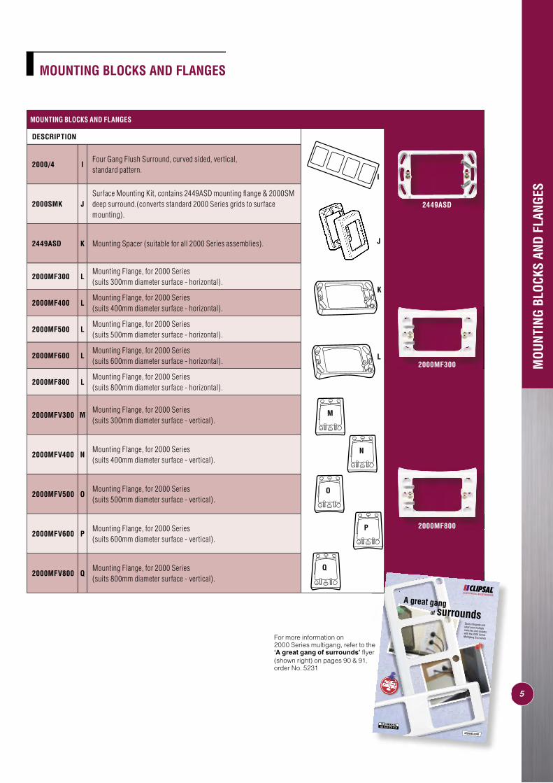
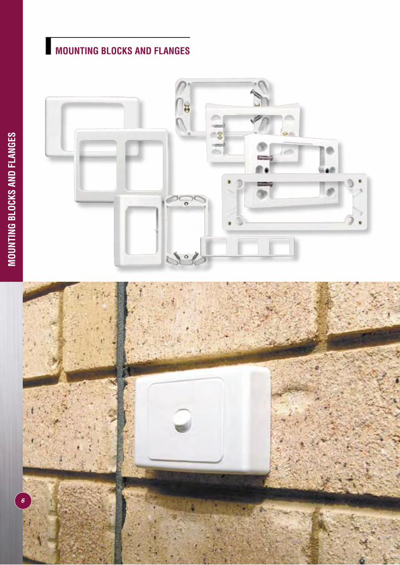
MOUNTING BLOCKS AND FLANGES
Cat. No. Length Width Depth Mounting Centres
2000 116mm 76mm 13mm N/A
2000SM 118mm 76mm 27mm N/A
2000/2 147.5mm 116mm 12.5mm N/A
2000H2 232mm 74.6mm 12mm N/A
2000/2R 146.35mm 115.5mm 12mm N/A
2000/3 219mm 116mm 12.5mm N/A
2000H3 348mm 74.6mm 12.05mm N/A
2000/3R 219mm 116mm 12.5mm N/A
2000/4 290.5mm 116mm 12.9mm N/A
2000SMK 118mm 78mm 27mm N/A
2449ASD 114mm 68mm 14mm 84mm apart
2000MF300 119mm 78mm 18mm 84mm apart
2000MF400 119mm 78mm 18mm 84mm apart
2000MF500 119mm 78mm 18mm 84mm apart
2000MF600 119mm 78mm 18mm 84mm apart
2000MF800 119mm 78mm 18mm 84mm apart
2000MFV300 119mm 78mm 18mm 84mm apart
2000MFV400 119mm 78mm 18mm 84mm apart
2000MFV500 119mm 78mm 18mm 84mm apart
2000MFV600 119mm 78mm 18mm 84mm apart
2000MFV800 119mm 78mm 18mm 84mm apart
DESCRIPTION
2000 A One Gang Flush Surround, for use with all 2000 Series grid assemblies.
2000SM BSurround, deep, surface mounting (designed for use with 2449ASD and all 2000 Series grid assemblies).
2000/2 C Two Gang Flush Surround, curved sided, standard pattern.
2000H2 D Two Gang Flush Surround, curved sided, horizontal, standard pattern.
2000/2R E Two Gang Surround, with round hole (suits 2009R).
2000/3 F Three Gang Flush Surround, curved sided, vertical, standard pattern.
2000H3 GThree Gang Flush Surround, curved sided, horizontal, standard pattern.
2000/3R H Three Gang Flush Surround, with round hole (suits 2009R).
MOU
NTIN
G BL
OCKS
AND
FLA
NGES
MOUNTING BLOCKS AND FLANGES
Clipsal mounting blocks give added safety to surface wiring installations.
The accessory mounting screw holes have sealed ends and mounting screws supplied cannot pierce live cables. All blocks are provided with ample cut-outs on all sides for convenient cable entry. The wall fi xing mounting holes are elongated for ease of adjustment when squaring up. Most mounting holes have metal inserts for perfect thread form.
2000SM
2000/2
2000H3
D
E
F
G
H
C
A
5
MOU
NTIN
G BL
OCKS
AND
FLA
NGES
MOUNTING BLOCKS AND FLANGES
MOUNTING BLOCKS AND FLANGES
DESCRIPTION
2000/4 IFour Gang Flush Surround, curved sided, vertical,standard pattern.
2000SMK JSurface Mounting Kit, contains 2449ASD mounting fl ange & 2000SM deep surround.(converts standard 2000 Series grids to surface mounting).
2449ASD K Mounting Spacer (suitable for all 2000 Series assemblies).
2000MF300 LMounting Flange, for 2000 Series (suits 300mm diameter surface - horizontal).
2000MF400 LMounting Flange, for 2000 Series (suits 400mm diameter surface - horizontal).
2000MF500 LMounting Flange, for 2000 Series (suits 500mm diameter surface - horizontal).
2000MF600 LMounting Flange, for 2000 Series (suits 600mm diameter surface - horizontal).
2000MF800 LMounting Flange, for 2000 Series (suits 800mm diameter surface - horizontal).
2000MFV300 MMounting Flange, for 2000 Series (suits 300mm diameter surface - vertical).
2000MFV400 NMounting Flange, for 2000 Series (suits 400mm diameter surface - vertical).
2000MFV500 OMounting Flange, for 2000 Series (suits 500mm diameter surface - vertical).
2000MFV600 PMounting Flange, for 2000 Series (suits 600mm diameter surface - vertical).
2000MFV800 QMounting Flange, for 2000 Series (suits 800mm diameter surface - vertical).
K
I
L
O
N
P
Q
������������������
������������������
����������������
�����������
������������������������
������������������������������������������������������������������������������������������������������
M
J
For more information on 2000 Series multigang, refer to the ‘A great gang of surrounds’ fl yer (shown right) on pages 90 & 91,order No. 5231
2000MF800
2449ASD
2000MF300
6
MOU
NTIN
G BL
OCKS
AND
FLA
NGES
MOUNTING BLOCKS AND FLANGES
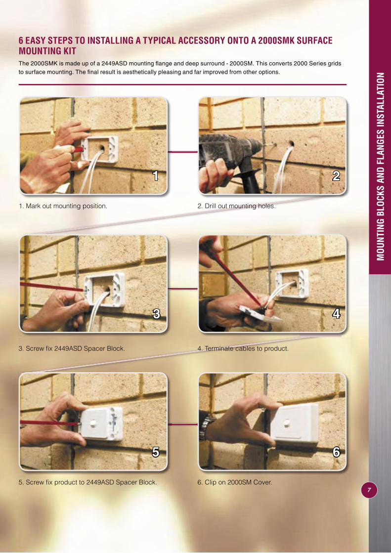
6 EASY STEPS TO INSTALLING A TYPICAL ACCESSORY ONTO A 2000SMK SURFACE MOUNTING KIT
1 2
3 4
5 6
1. Mark out mounting position. 2. Drill out mounting holes.
3. Screw fi x 2449ASD Spacer Block. 4. Terminate cables to product.
5. Screw fi x product to 2449ASD Spacer Block. 6. Clip on 2000SM Cover.
MOU
NTIN
G BL
OCKS
AND
FLA
NGES
INST
ALLA
TION
The 2000SMK is made up of a 2449ASD mounting fl ange and deep surround - 2000SM. This converts 2000 Series grids to surface mounting. The fi nal result is aesthetically pleasing and far improved from other options.
7
8
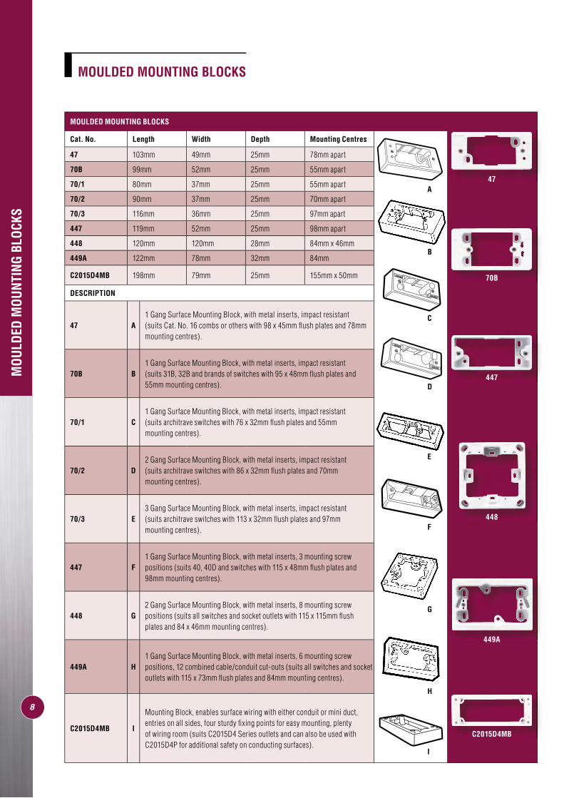
MOULDED MOUNTING BLOCKS
Cat. No. Length Width Depth Mounting Centres
47 103mm 49mm 25mm 78mm apart
70B 99mm 52mm 25mm 55mm apart
70/1 80mm 37mm 25mm 55mm apart
70/2 90mm 37mm 25mm 70mm apart
70/3 116mm 36mm 25mm 97mm apart
447 119mm 52mm 25mm 98mm apart
448 120mm 120mm 28mm 84mm x 46mm
449A 122mm 78mm 32mm 84mm
C2015D4MB 198mm 79mm 25mm 155mm x 50mm
DESCRIPTION
47 A1 Gang Surface Mounting Block, with metal inserts, impact resistant (suits Cat. No. 16 combs or others with 98 x 45mm fl ush plates and 78mm mounting centres).
70B B1 Gang Surface Mounting Block, with metal inserts, impact resistant (suits 31B, 32B and brands of switches with 95 x 48mm fl ush plates and 55mm mounting centres).
70/1 C1 Gang Surface Mounting Block, with metal inserts, impact resistant (suits architrave switches with 76 x 32mm fl ush plates and 55mm mounting centres).
70/2 D2 Gang Surface Mounting Block, with metal inserts, impact resistant (suits architrave switches with 86 x 32mm fl ush plates and 70mm mounting centres).
70/3 E3 Gang Surface Mounting Block, with metal inserts, impact resistant (suits architrave switches with 113 x 32mm fl ush plates and 97mm mounting centres).
447 F1 Gang Surface Mounting Block, with metal inserts, 3 mounting screw positions (suits 40, 40D and switches with 115 x 48mm fl ush plates and 98mm mounting centres).
448 G2 Gang Surface Mounting Block, with metal inserts, 8 mounting screw positions (suits all switches and socket outlets with 115 x 115mm fl ush plates and 84 x 46mm mounting centres).
449A H1 Gang Surface Mounting Block, with metal inserts, 6 mounting screw positions, 12 combined cable/conduit cut-outs (suits all switches and socket outlets with 115 x 73mm fl ush plates and 84mm mounting centres).
C2015D4MB I
Mounting Block, enables surface wiring with either conduit or mini duct, entries on all sides, four sturdy fi xing points for easy mounting, plenty of wiring room (suits C2015D4 Series outlets and can also be used with C2015D4P for additional safety on conducting surfaces).
MOU
LDED
MOU
NTIN
G BL
OCKS
C
F
A
D
B
E
G
H
I
MOULDED MOUNTING BLOCKS
47
70B
447
449A
C2015D4MB
448
9
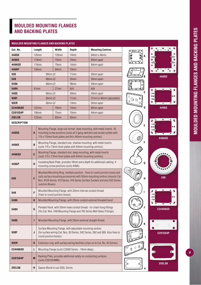
MOULDED MOUNTING FLANGES AND BACKING PLATES
Cat. No. Length Width Depth Mounting Centres
448SD 120mm 120mm 14mm 84mm x 46mm
449AS 119mm 74mm 10mm 84mm apart
449ASD 119mm 79mm 14mm 84mm apart
449AP 126mm 84mm 10mm -
536 90mm ∅ 11mm 50mm apart
548 66mm ∅ 35mm 50mm apart
548A 66mm ∅ 98mm 50mm apart
548H 41mm 27mm N/A N/A
548S 66mm ∅ 59mm 50mm apart
93BF 66mm ∅ 11mm 37mm to 46mm (adjustable)
93ER 66mm ∅ 13mm 50mm apart
C2449ASD 122mm 79mm 14mm 84mm apart
C2015D4P 196mm 75mm 10mm 84mm apart
25ELSB 122mm 83mm 30mm -
DESCRIPTION
448SD AMounting Flange, large size format, deep mounting, with metal inserts, 16 mounting screw positions (suits all 2 gang switches and socket outlets with 115 x 115mm fl ush plates and 84 x 46mm mounting centres).
449AS BMounting Flange, standard size, shallow mounting, with metal inserts (suits 115 x 73mm fl ush plates with 84mm mounting centres).
449ASD CMounting Flange, standard size, deep mounting, with metal inserts (suits 115 x 73mm fl ush plates with 84mm mounting centres).
449AP DInsulating Back Plate, provides 10mm extra depth for additional cabling, 4 mounting screw positions (suits 449A).
536 E
Moulded Mounting Ring, multiple position - fi xes to round junction boxes and suits surface mounting accessories with 50mm mounting centres (mounts Cat. Nos. 412A Series, 413 Series, 414 Series Surface Sockets and also 555 Series Junction Boxes).
548 FMoulded Mounting Flange, with 20mm internal conduit thread (fi xes to round junction boxes).
548A G Moulded Mounting Flange, with 20mm conduit external threaded bend.
548H HPendant Hook, with 20mm male conduit thread - for chain hung fi ttings (fi ts Cat. Nos. 548 Mounting Flange and 745 Series Well Glass Fittings).
548S I Moulded Mounting Flange, with 20mm external straight thread.
93BF JSurface Mounting Flange, with adjustable mounting centres (for surface wiring Cat. Nos. 93 Series, 342 Series, 362 and 389. Also fi xes to round junction boxes).
93ER K Extension ring, with surface wiring facilities (clips on to Cat. No. 93 Series).
C2449ASD L Mounting Flange (suits C2000 Series - 14mm deep).
C2015D4P MBacking Plate, provides additional safety on conducting surfaces (suits C2015D4MB).
25ELSB N Spacer Block to suit 25EL Series.
MOU
LDED
MOU
NTIN
G FL
ANGE
S AN
D BA
CKIN
G PL
ATES
E
L
A
B
C
D
G
J
K
F
M
H
I
N
MOULDED MOUNTING FLANGES AND BACKING PLATES
448SD
449AS
449ASD
536
C2449ASD
C2015D4P
25ELSB
SPEC
IAL
PURP
OSE
MOU
NTIN
G BL
OCKS
AND
LO
OM W
IRIN
G FI
PLA
TES
10
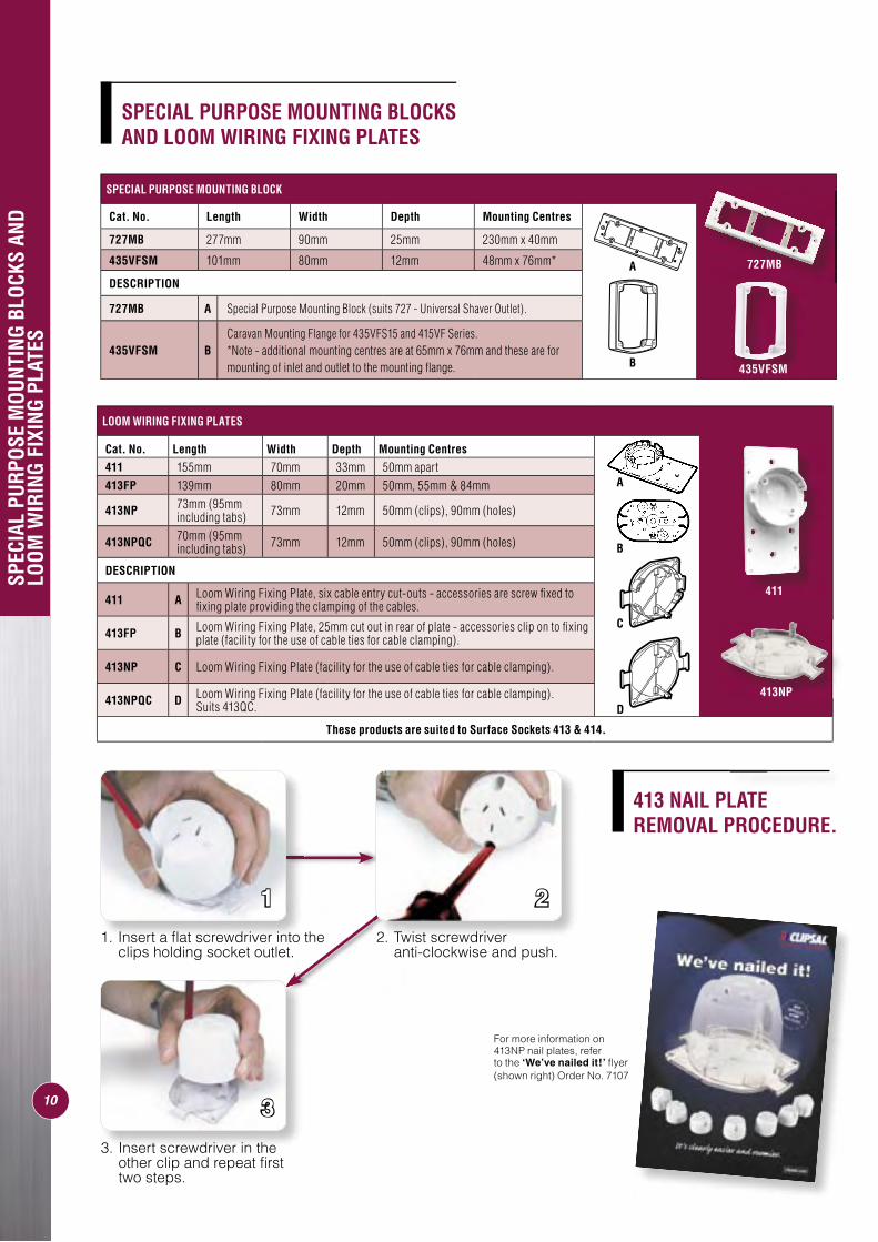
LOOM WIRING FIXING PLATES
Cat. No. Length Width Depth Mounting Centres
411 155mm 70mm 33mm 50mm apart413FP 139mm 80mm 20mm 50mm, 55mm & 84mm
413NP 73mm (95mm including tabs) 73mm 12mm 50mm (clips), 90mm (holes)
413NPQC 70mm (95mm including tabs) 73mm 12mm 50mm (clips), 90mm (holes)
DESCRIPTION
411 A Loom Wiring Fixing Plate, six cable entry cut-outs - accessories are screw fi xed to fi xing plate providing the clamping of the cables.
413FP B Loom Wiring Fixing Plate, 25mm cut out in rear of plate - accessories clip on to fi xing plate (facility for the use of cable ties for cable clamping).
413NP C Loom Wiring Fixing Plate (facility for the use of cable ties for cable clamping).
413NPQC D Loom Wiring Fixing Plate (facility for the use of cable ties for cable clamping). Suits 413QC.
These products are suited to Surface Sockets 413 & 414.
1 2
3
SPECIAL PURPOSE MOUNTING BLOCK
Cat. No. Length Width Depth Mounting Centres
727MB 277mm 90mm 25mm 230mm x 40mm
435VFSM 101mm 80mm 12mm 48mm x 76mm*
DESCRIPTION
727MB A Special Purpose Mounting Block (suits 727 - Universal Shaver Outlet).
435VFSM BCaravan Mounting Flange for 435VFS15 and 415VF Series.*Note - additional mounting centres are at 65mm x 76mm and these are for mounting of inlet and outlet to the mounting fl ange.
SPECIAL PURPOSE MOUNTING BLOCKS AND LOOM WIRING FIXING PLATES
A
A
B
C
D
2. Twist screwdriver anti-clockwise and push.
1. Insert a fl at screwdriver into the clips holding socket outlet.
727MB
411
413NP
413 NAIL PLATE REMOVAL PROCEDURE.
For more information on 413NP nail plates, refer to the ‘We’ve nailed it!’ fl yer(shown right) Order No. 7107
3. Insert screwdriver in the other clip and repeat fi rst two steps.
435VFSMB
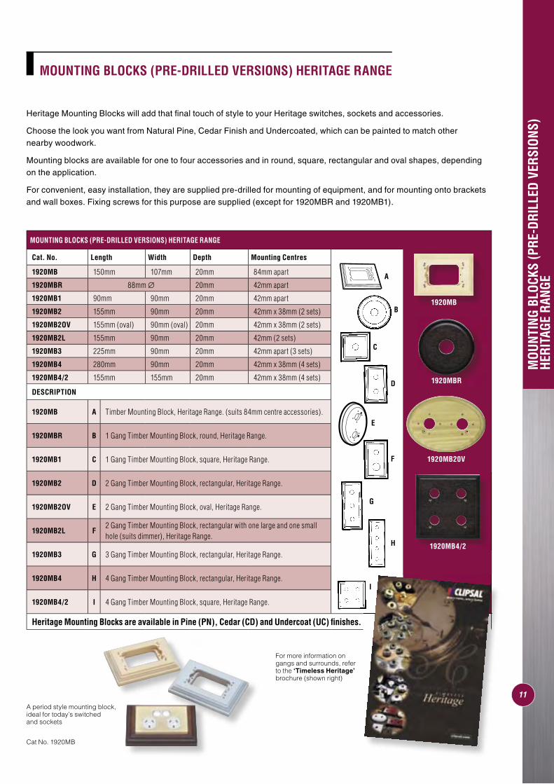
Heritage Mounting Blocks will add that fi nal touch of style to your Heritage switches, sockets and accessories.
Choose the look you want from Natural Pine, Cedar Finish and Undercoated, which can be painted to match other nearby woodwork.
Mounting blocks are available for one to four accessories and in round, square, rectangular and oval shapes, depending on the application.
For convenient, easy installation, they are supplied pre-drilled for mounting of equipment, and for mounting onto brackets and wall boxes. Fixing screws for this purpose are supplied (except for 1920MBR and 1920MB1).
MOUNTING BLOCKS (PRE-DRILLED VERSIONS) HERITAGE RANGE
Cat. No. Length Width Depth Mounting Centres
1920MB 150mm 107mm 20mm 84mm apart
1920MBR 88mm ∅ 20mm 42mm apart
1920MB1 90mm 90mm 20mm 42mm apart
1920MB2 155mm 90mm 20mm 42mm x 38mm (2 sets)
1920MB2OV 155mm (oval) 90mm (oval) 20mm 42mm x 38mm (2 sets)
1920MB2L 155mm 90mm 20mm 42mm (2 sets)
1920MB3 225mm 90mm 20mm 42mm apart (3 sets)
1920MB4 280mm 90mm 20mm 42mm x 38mm (4 sets)
1920MB4/2 155mm 155mm 20mm 42mm x 38mm (4 sets)
DESCRIPTION
1920MB A Timber Mounting Block, Heritage Range. (suits 84mm centre accessories).
1920MBR B 1 Gang Timber Mounting Block, round, Heritage Range.
1920MB1 C 1 Gang Timber Mounting Block, square, Heritage Range.
1920MB2 D 2 Gang Timber Mounting Block, rectangular, Heritage Range.
1920MB2OV E 2 Gang Timber Mounting Block, oval, Heritage Range.
1920MB2L F2 Gang Timber Mounting Block, rectangular with one large and one small hole (suits dimmer), Heritage Range.
1920MB3 G 3 Gang Timber Mounting Block, rectangular, Heritage Range.
1920MB4 H 4 Gang Timber Mounting Block, rectangular, Heritage Range.
1920MB4/2 I 4 Gang Timber Mounting Block, square, Heritage Range.
Heritage Mounting Blocks are available in Pine (PN), Cedar (CD) and Undercoat (UC) fi nishes.
MOU
NTIN
G BL
OCKS
(PRE
-DRI
LLED
VER
SION
S)
HERI
TAGE
RAN
GE
MOUNTING BLOCKS (PRE-DRILLED VERSIONS) HERITAGE RANGE
11
A
B
C
D
E
F
G
H
I
1920MB
1920MBR
1920MB20V
1920MB4/2
For more information on gangs and surrounds, refer to the ‘Timeless Heritage’ brochure (shown right)
A period style mounting block, ideal for today’s switched and sockets
Cat No. 1920MB
MOU
NTIN
G BL
OCKS
(BLA
NK V
ERSI
ONS)
HE
RITA
GE R
ANGE
12
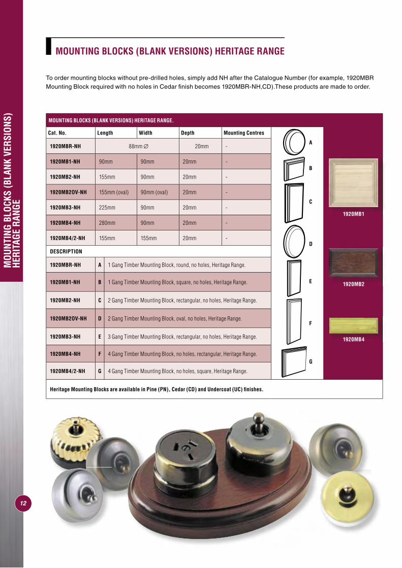
MOUNTING BLOCKS (BLANK VERSIONS) HERITAGE RANGE
MOUNTING BLOCKS (BLANK VERSIONS) HERITAGE RANGE.
Cat. No. Length Width Depth Mounting Centres
1920MBR-NH 88mm ∅ 20mm -
1920MB1-NH 90mm 90mm 20mm -
1920MB2-NH 155mm 90mm 20mm -
1920MB2OV-NH 155mm (oval) 90mm (oval) 20mm -
1920MB3-NH 225mm 90mm 20mm -
1920MB4-NH 280mm 90mm 20mm -
1920MB4/2-NH 155mm 155mm 20mm -
DESCRIPTION
1920MBR-NH A 1 Gang Timber Mounting Block, round, no holes, Heritage Range.
1920MB1-NH B 1 Gang Timber Mounting Block, square, no holes, Heritage Range.
1920MB2-NH C 2 Gang Timber Mounting Block, rectangular, no holes, Heritage Range.
1920MB2OV-NH D 2 Gang Timber Mounting Block, oval, no holes, Heritage Range.
1920MB3-NH E 3 Gang Timber Mounting Block, rectangular, no holes, Heritage Range.
1920MB4-NH F 4 Gang Timber Mounting Block, no holes, rectangular, Heritage Range.
1920MB4/2-NH G 4 Gang Timber Mounting Block, no holes, square, Heritage Range.
Heritage Mounting Blocks are available in Pine (PN), Cedar (CD) and Undercoat (UC) fi nishes.
A
D
G
B
C
E
F
1920MB2
1920MB4
1920MB1
To order mounting blocks without pre-drilled holes, simply add NH after the Catalogue Number (for example, 1920MBR Mounting Block required with no holes in Cedar fi nish becomes 1920MBR-NH,CD).These products are made to order.
MOU
NTIN
G BL
OCKS
ENT
RY T
YPES
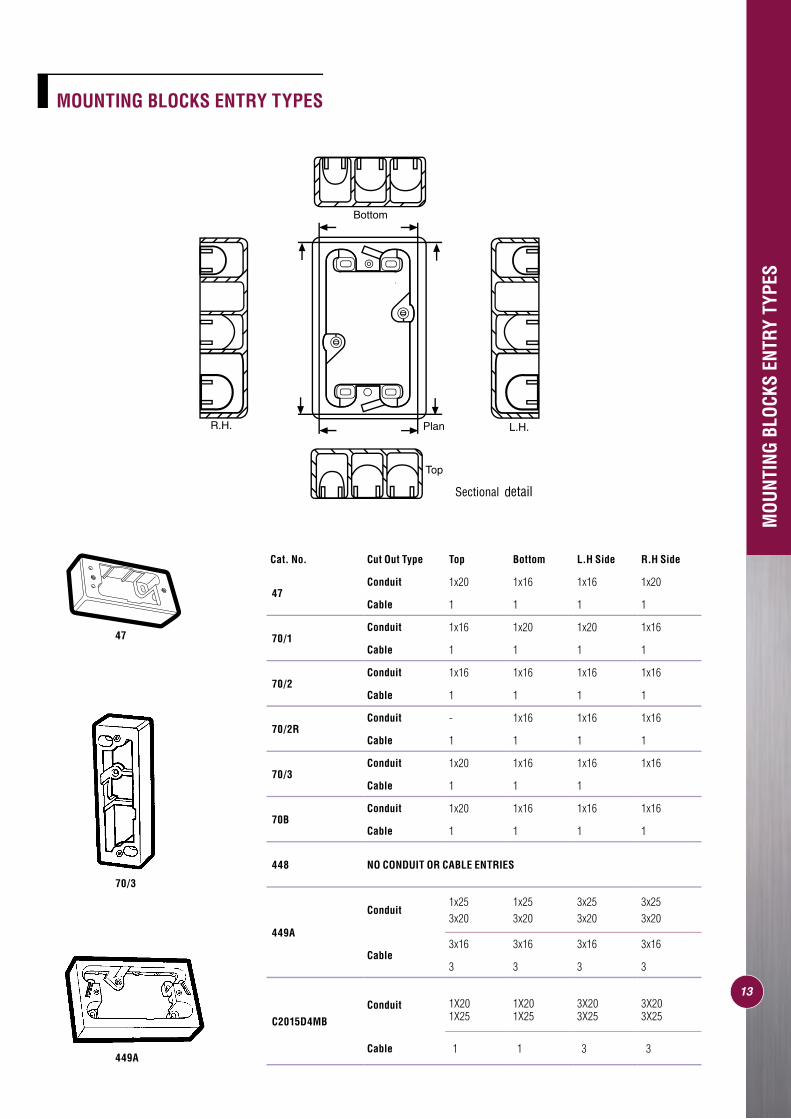
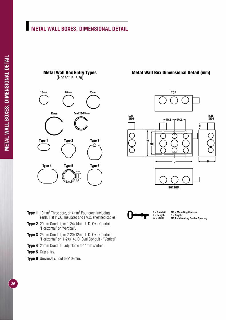
MOUNTING BLOCKS ENTRY TYPES
MOUNTING BLOCKS
Cat. No. Cut Out Type Top Bottom L.H Side R.H Side
47 Conduit 1x20 1x16 1x16 1x20
Cable 1 1 1 1
70/1Conduit 1x16 1x20 1x20 1x16
Cable 1 1 1 1
70/2Conduit 1x16 1x16 1x16 1x16
Cable 1 1 1 1
70/2RConduit - 1x16 1x16 1x16
Cable 1 1 1 1
70/3Conduit 1x20 1x16 1x16 1x16
Cable 1 1 1
70BConduit 1x20 1x16 1x16 1x16
Cable 1 1 1 1
448 NO CONDUIT OR CABLE ENTRIES
449A
Conduit1x25 1x25 3x25 3x253x20 3x20 3x20 3x20
Cable3x16 3x16 3x16 3x16
3 3 3 3
C2015D4MB
Conduit 1X20 1X20 3X20 3X201X25 1X25 3X25 3X25
Cable 1 1 3 3449A
70/3
47
13
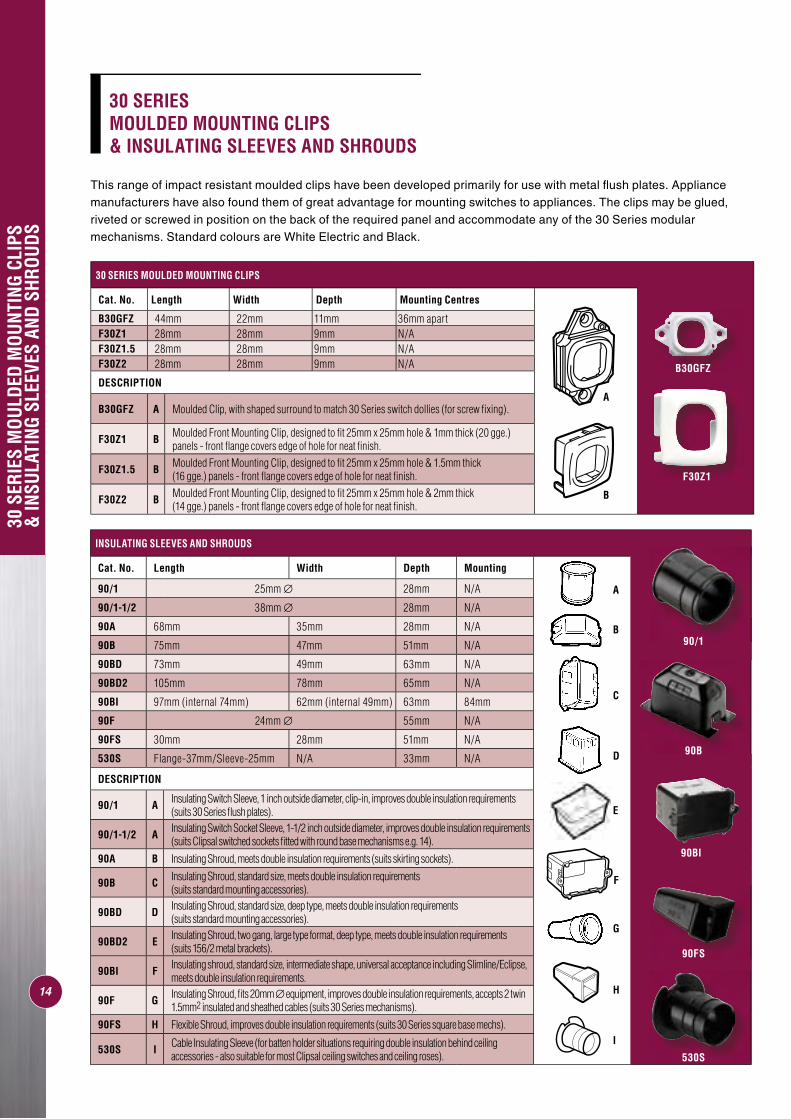
INSULATING SLEEVES AND SHROUDS
Cat. No. Length Width Depth Mounting
90/1 25mm ∅ 28mm N/A
90/1-1/2 38mm ∅ 28mm N/A
90A 68mm 35mm 28mm N/A
90B 75mm 47mm 51mm N/A
90BD 73mm 49mm 63mm N/A
90BD2 105mm 78mm 65mm N/A
90BI 97mm (internal 74mm) 62mm (internal 49mm) 63mm 84mm
90F 24mm ∅ 55mm N/A
90FS 30mm 28mm 51mm N/A
530S Flange-37mm/Sleeve-25mm N/A 33mm N/A
DESCRIPTION
90/1 A Insulating Switch Sleeve, 1 inch outside diameter, clip-in, improves double insulation requirements (suits 30 Series fl ush plates).
90/1-1/2 A Insulating Switch Socket Sleeve, 1-1/2 inch outside diameter, improves double insulation requirements (suits Clipsal switched sockets fi tted with round base mechanisms e.g. 14).
90A B Insulating Shroud, meets double insulation requirements (suits skirting sockets).
90B C Insulating Shroud, standard size, meets double insulation requirements (suits standard mounting accessories).
90BD D Insulating Shroud, standard size, deep type, meets double insulation requirements (suits standard mounting accessories).
90BD2 E Insulating Shroud, two gang, large type format, deep type, meets double insulation requirements (suits 156/2 metal brackets).
90BI F Insulating shroud, standard size, intermediate shape, universal acceptance including Slimline/Eclipse, meets double insulation requirements.
90F G Insulating Shroud, fi ts 20mm ∅ equipment, improves double insulation requirements, accepts 2 twin 1.5mm2 insulated and sheathed cables (suits 30 Series mechanisms).
90FS H Flexible Shroud, improves double insulation requirements (suits 30 Series square base mechs).
530S I Cable Insulating Sleeve (for batten holder situations requiring double insulation behind ceiling accessories - also suitable for most Clipsal ceiling switches and ceiling roses).
H
A
B
C
D
E
G
I
F
30 S
ERIE
S M
OULD
ED M
OUNT
ING
CLIP
S &
INSU
LATI
NG S
LEEV
ES A
ND S
HROU
DS
30 SERIES MOULDED MOUNTING CLIPS
Cat. No. Length Width Depth Mounting Centres
B30GFZ 44mm 22mm 11mm 36mm apartF30Z1 28mm 28mm 9mm N/AF30Z1.5 28mm 28mm 9mm N/AF30Z2 28mm 28mm 9mm N/A
DESCRIPTION
B30GFZ A Moulded Clip, with shaped surround to match 30 Series switch dollies (for screw fi xing).
F30Z1 B Moulded Front Mounting Clip, designed to fi t 25mm x 25mm hole & 1mm thick (20 gge.) panels - front fl ange covers edge of hole for neat fi nish.
F30Z1.5 B Moulded Front Mounting Clip, designed to fi t 25mm x 25mm hole & 1.5mm thick (16 gge.) panels - front fl ange covers edge of hole for neat fi nish.
F30Z2 B Moulded Front Mounting Clip, designed to fi t 25mm x 25mm hole & 2mm thick (14 gge.) panels - front fl ange covers edge of hole for neat fi nish.
A
B
14
30 SERIES MOULDED MOUNTING CLIPS & INSULATING SLEEVES AND SHROUDS
This range of impact resistant moulded clips have been developed primarily for use with metal fl ush plates. Appliance manufacturers have also found them of great advantage for mounting switches to appliances. The clips may be glued, riveted or screwed in position on the back of the required panel and accommodate any of the 30 Series modular mechanisms. Standard colours are White Electric and Black.
90/1
90B
90FS
530S
B30GFZ
F30Z1
90BI
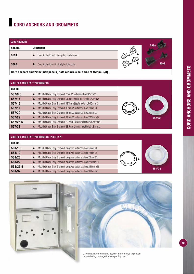
CORD ANCHORS
Cat. No. Description
569A A Cord Anchor to suit ordinary duty fl exible cords.
569B B Cord Anchor to suit light duty fl exible cords.
Cord anchors suit 2mm thick panels, both require a hole size of 16mm (5/8).
CORD
ANC
HORS
AND
GRO
MM
ETS
CORD ANCHORS AND GROMMETS
MOULDED CABLE ENTRY GROMMETS
Cat. No.
567/9.5 A Moulded Cable Entry Grommet, 8mm ∅, suits metal hole 9.5mm ∅.
567/13 A Moulded Cable Entry Grommet, 9.5mm ∅, suits metal hole 12.7mm ∅.
567/16 A Moulded Cable Entry Grommet, 12.7mm ∅, suits metal hole 16mm ∅.
567/19 A Moulded Cable Entry Grommet, 16mm ∅, suits metal hole 19mm ∅.
567/20 A Moulded Cable Entry Grommet, 16mm ∅, suits metal hole 20mm ∅.
567/22 A Moulded Cable Entry Grommet, 19mm ∅, suits metal hole 22.2mm ∅.
567/25.5 A Moulded Cable Entry Grommet, 22.2mm ∅, suits metal hole 25.5mm ∅.
567/32 A Moulded Cable Entry Grommet, 28.5mm ∅, suits metal hole 31.8mm ∅.
MOULDED CABLE ENTRY GROMMETS - PLUG TYPE
Cat. No.
568/16 A Moulded Cable Entry Grommet, plug type, suits metal hole 16mm ∅.
568/19 A Moulded Cable Entry Grommet, plug type, suits metal hole 19mm ∅.
568/20 A Moulded Cable Entry Grommet, plug type, suits metal hole 20mm ∅.
568/22 A Moulded Cable Entry Grommet, plug type, suits metal hole 22.2mm ∅.
568/25.5 A Moulded Cable Entry Grommet, plug type, suits metal hole 25.5mm ∅.
568/32 A Moulded Cable Entry Grommet, plug type, suits metal hole 31.8mm ∅.
A
15
A
B
A
569A
569B
567/32
568/ 32
Grommets are commonly used in meter boxes to prevent cables being damaged at entry/exit points.

MOUNTING BRACKETS, PLATES AND CLIPS
Clipsal offers a bracket for all applications. They are designed to suit almost every method of building construction used today. Models are available for timber stud fi xing, direct wall board mounting or for direct fastening to brickwork prior to plastering. Brackets are precision stamped.
MOU
NTIN
G BR
ACKE
TS, P
LATE
S AN
D CL
IPS
16
A
B
C
E
F
G
D
MOU
NTIN
G BR
ACKE
TS A
ND C
LIPS
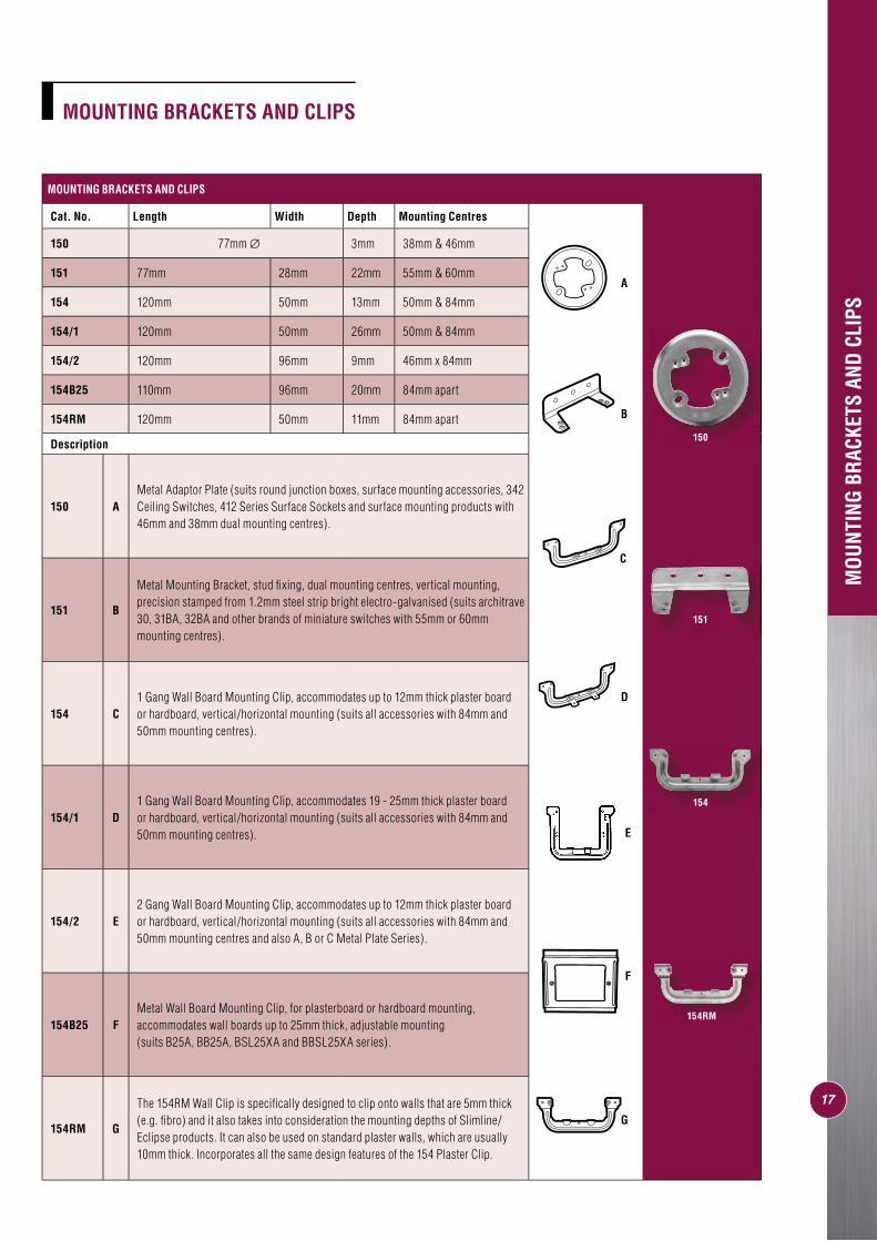
MOUNTING BRACKETS AND CLIPS
Cat. No. Length Width Depth Mounting Centres
150 77mm ∅ 3mm 38mm & 46mm
151 77mm 28mm 22mm 55mm & 60mm
154 120mm 50mm 13mm 50mm & 84mm
154/1 120mm 50mm 26mm 50mm & 84mm
154/2 120mm 96mm 9mm 46mm x 84mm
154B25 110mm 96mm 20mm 84mm apart
154RM 120mm 50mm 11mm 84mm apart
Description
150 AMetal Adaptor Plate (suits round junction boxes, surface mounting accessories, 342 Ceiling Switches, 412 Series Surface Sockets and surface mounting products with 46mm and 38mm dual mounting centres).
151 B
Metal Mounting Bracket, stud fi xing, dual mounting centres, vertical mounting, precision stamped from 1.2mm steel strip bright electro-galvanised (suits architrave 30, 31BA, 32BA and other brands of miniature switches with 55mm or 60mm mounting centres).
154 C1 Gang Wall Board Mounting Clip, accommodates up to 12mm thick plaster board or hardboard, vertical/horizontal mounting (suits all accessories with 84mm and 50mm mounting centres).
154/1 D1 Gang Wall Board Mounting Clip, accommodates 19 - 25mm thick plaster board or hardboard, vertical/horizontal mounting (suits all accessories with 84mm and 50mm mounting centres).
154/2 E2 Gang Wall Board Mounting Clip, accommodates up to 12mm thick plaster board or hardboard, vertical/horizontal mounting (suits all accessories with 84mm and 50mm mounting centres and also A, B or C Metal Plate Series).
154B25 FMetal Wall Board Mounting Clip, for plasterboard or hardboard mounting, accommodates wall boards up to 25mm thick, adjustable mounting (suits B25A, BB25A, BSL25XA and BBSL25XA series).
154RM G
The 154RM Wall Clip is specifi cally designed to clip onto walls that are 5mm thick (e.g. fi bro) and it also takes into consideration the mounting depths of Slimline/Eclipse products. It can also be used on standard plaster walls, which are usually 10mm thick. Incorporates all the same design features of the 154 Plaster Clip.
MOUNTING BRACKETS AND CLIPS
17
150
151
154
154RM
A
C
B
F
G
E
D
18
MOU
NTIN
G BR
ACKE
TS
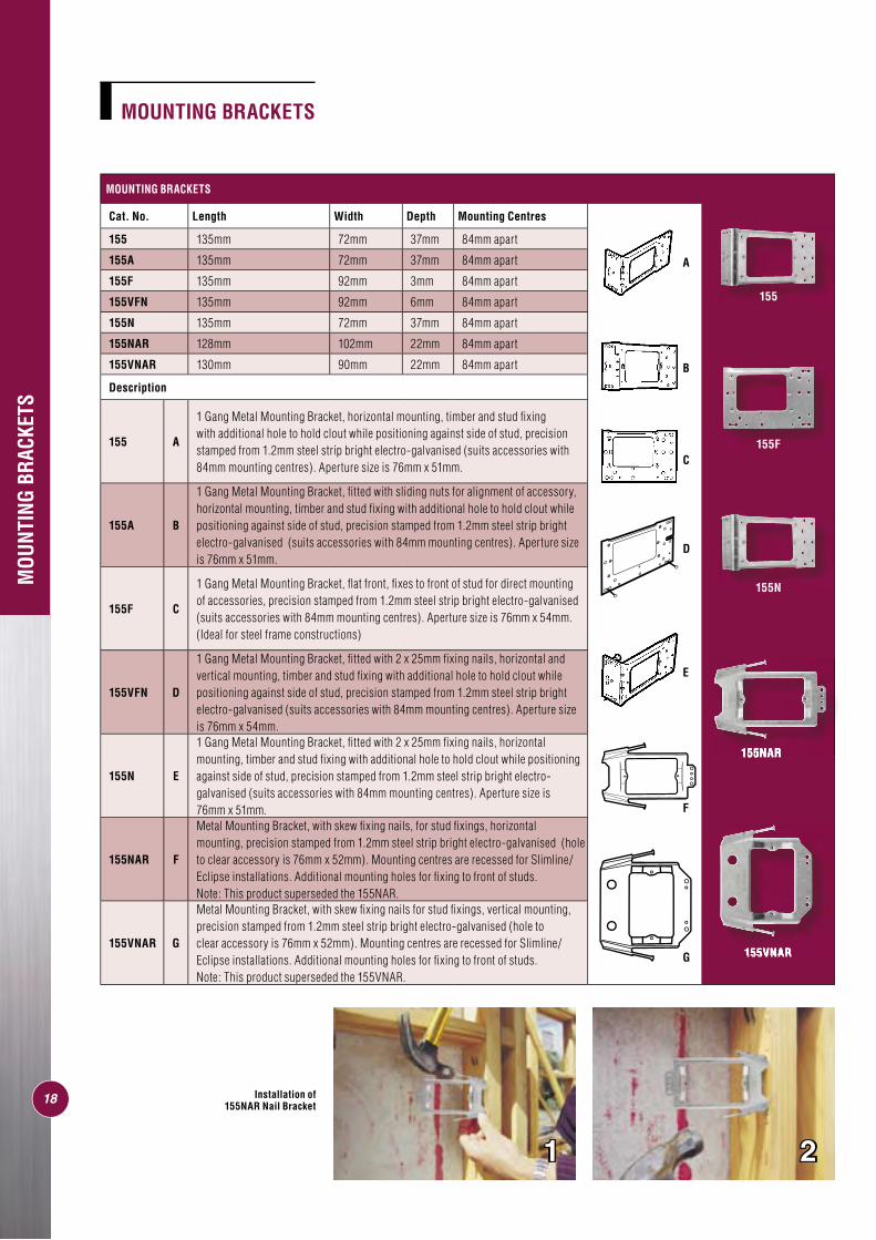
MOUNTING BRACKETS
Cat. No. Length Width Depth Mounting Centres
155 135mm 72mm 37mm 84mm apart
155A 135mm 72mm 37mm 84mm apart
155F 135mm 92mm 3mm 84mm apart
155VFN 135mm 92mm 6mm 84mm apart
155N 135mm 72mm 37mm 84mm apart
155NAR 128mm 102mm 22mm 84mm apart
155VNAR 130mm 90mm 22mm 84mm apart
Description
155 A
1 Gang Metal Mounting Bracket, horizontal mounting, timber and stud fi xing with additional hole to hold clout while positioning against side of stud, precision stamped from 1.2mm steel strip bright electro-galvanised (suits accessories with 84mm mounting centres). Aperture size is 76mm x 51mm.
155A B
1 Gang Metal Mounting Bracket, fi tted with sliding nuts for alignment of accessory, horizontal mounting, timber and stud fi xing with additional hole to hold clout while positioning against side of stud, precision stamped from 1.2mm steel strip bright electro-galvanised (suits accessories with 84mm mounting centres). Aperture size is 76mm x 51mm.
155F C
1 Gang Metal Mounting Bracket, fl at front, fi xes to front of stud for direct mounting of accessories, precision stamped from 1.2mm steel strip bright electro-galvanised (suits accessories with 84mm mounting centres). Aperture size is 76mm x 54mm.(Ideal for steel frame constructions)
155VFN D
1 Gang Metal Mounting Bracket, fi tted with 2 x 25mm fi xing nails, horizontal and vertical mounting, timber and stud fi xing with additional hole to hold clout while positioning against side of stud, precision stamped from 1.2mm steel strip bright electro-galvanised (suits accessories with 84mm mounting centres). Aperture size is 76mm x 54mm.
155N E
1 Gang Metal Mounting Bracket, fi tted with 2 x 25mm fi xing nails, horizontal mounting, timber and stud fi xing with additional hole to hold clout while positioning against side of stud, precision stamped from 1.2mm steel strip bright electro-galvanised (suits accessories with 84mm mounting centres). Aperture size is 76mm x 51mm.
155NAR F
Metal Mounting Bracket, with skew fi xing nails, for stud fi xings, horizontal mounting, precision stamped from 1.2mm steel strip bright electro-galvanised (hole to clear accessory is 76mm x 52mm). Mounting centres are recessed for Slimline/Eclipse installations. Additional mounting holes for fi xing to front of studs. Note: This product superseded the 155NAR.
155VNAR G
Metal Mounting Bracket, with skew fi xing nails for stud fi xings, vertical mounting, precision stamped from 1.2mm steel strip bright electro-galvanised (hole to clear accessory is 76mm x 52mm). Mounting centres are recessed for Slimline/Eclipse installations. Additional mounting holes for fi xing to front of studs.Note: This product superseded the 155VNAR.
MOUNTING BRACKETS
155
155F
155N
155NAR155NAR
155VNAR155VNAR
1 2
Installation of 155NAR Nail Bracket
19
MOU
NTIN
G BR
ACKE
TS
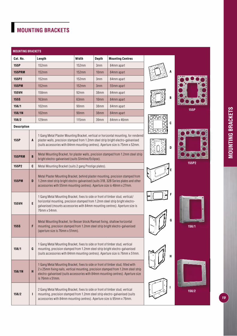
MOUNTING BRACKETS
Cat. No. Length Width Depth Mounting Centres
155P 152mm 152mm 3mm 84mm apart
155PRM 152mm 152mm 10mm 84mm apart
155P2 152mm 152mm 3mm 84mm apart
155PM 152mm 152mm 3mm 55mm apart
155VH 158mm 92mm 38mm 84mm apart
155S 163mm 63mm 10mm 84mm apart
156/1 102mm 90mm 38mm 84mm apart
156/1N 102mm 90mm 38mm 84mm apart
156/2 129mm 115mm 39mm 84mm x 46mm
Description
155P A1 Gang Metal Plaster Mounting Bracket, vertical or horizontal mounting, for rendered plaster walls, precision stamped from 1.2mm steel strip bright electro-galvanised (suits accessories with 84mm mounting centres). Aperture size is 75mm x 52mm.
155PRM BMetal Mounting Bracket, for plaster walls, precision stamped from 1.2mm steel strip bright electro-galvanised (suits Slimline/Eclipse).
155P2 C Metal Mounting Bracket (suits 2 gang Prestige plates).
155PM DMetal Plaster Mounting Bracket, behind plaster mounting, precision stamped from 1.2mm steel strip bright electro-galvanised (suits 31B, 32B Series plates and other accessories with 55mm mounting centres). Aperture size is 48mm x 27mm.
155VH E
1 Gang Metal Mounting Bracket, fi xes to side or front of timber stud, vertical/horizontal mounting, precision stamped from 1.2mm steel strip bright electro-galvanised (mounts accessories with 84mm mounting centres). Aperture size is 76mm x 54mm.
155S FMetal Mounting Bracket, for Besser block/Ramset fi xing, shallow horizontal mounting, precision stamped from 1.2mm steel strip bright electro-galvanised (aperture size is 76mm x 51mm).
156/1 G1 Gang Metal Mounting Bracket, fi xes to side or front of timber stud, vertical mounting, precision stamped from 1.2mm steel strip bright electro-galvanised (suits accessories with 84mm mounting centres). Aperture size is 76mm x 51mm.
156/1N H
1 Gang Metal Mounting Bracket, fi xes to side or front of timber stud, fi tted with 2 x 25mm fi xing nails, vertical mounting, precision stamped from 1.2mm steel strip electro-galvanised (suits accessories with 84mm mounting centres). Aperture size is 76mm x 51mm.
156/2 I2 Gang Metal Mounting Bracket, fi xes to side or front of timber stud, vertical mounting, precision stamped from 1.2mm steel strip electro-galvanised (suits accessories with 84mm mounting centres). Aperture size is 95mm x 76mm.
MOUNTING BRACKETS
A
D
C
E
F
H
I
G
B
155P
155P2
156/1
156/2
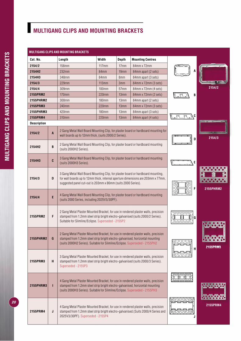
MULTIGANG CLIPS AND MOUNTING BRACKETS
Cat. No. Length Width Depth Mounting Centres
2154/2 158mm 117mm 17mm 84mm x 72mm
2154H2 232mm 84mm 19mm 84mm apart (2 sets)
2154H3 348mm 84mm 8mm 84mm apart (3 sets)
2154/3 229mm 113mm 3mm 84mm x 72mm (3 sets)
2154/4 309mm 100mm 57mm 84mm x 72mm (4 sets)
2155PRM2 170mm 220mm 13mm 84mm x 72mm (2 sets)
2155PHRM2 300mm 180mm 13mm 84mm apart (2 sets)
2155PRM3 240mm 220mm 13mm 84mm x 72mm (3 sets)
2155PHRM3 420mm 180mm 13mm 84mm apart (3 sets)
2155PRM4 310mm 220mm 13mm 84mm apart (4 sets)
Description
2154/2 A2 Gang Metal Wall Board Mounting Clip, for plaster board or hardboard mounting for wall boards up to 12mm thick, (suits 2000/2 Series).
2154H2 B2 Gang Metal Wall Board Mounting Clip, for plaster board or hardboard mounting (suits 2000H2 Series).
2154H3 C3 Gang Metal Wall Board Mounting Clip, for plaster board or hardboard mounting (suits 2000H3 Series).
2154/3 D3 Gang Metal Wall Board Mounting Clip, for plaster board or hardboard mounting, for wall boards up to 12mm thick, internal aperture dimensions are 203mm x 77mm, suggested panel cut-out is 203mm x 86mm (suits 2000 Series).
2154/4 E4 Gang Metal Wall Board Mounting Clip, for plaster board or hardboard mounting (suits 2000 Series, including 2025V3/30PF).
2155PRM2 F2 Gang Metal Plaster Mounted Bracket, for use in rendered plaster walls, precision stamped from 1.2mm steel strip bright electro-galvanised (suits 2000/2 Series). Suitable for Slimline/Eclipse. Superseded - 2155P2
2155PHRM2 G2 Gang Metal Plaster Mounted Bracket, for use in rendered plaster walls, precision stamped from 1.2mm steel strip bright electro-galvanised, horizontal mounting (suits 2000H2 Series). Suitable for Slimline/Eclipse. Superseded - 2155PH2
2155PRM3 H3 Gang Metal Plaster Mounted Bracket, for use in rendered plaster walls, precision stamped from 1.2mm steel strip bright electro-galvanised (suits 2000/3 Series).Superseded - 2155P3
2155PHRM3 I4 Gang Metal Plaster Mounted Bracket, for use in rendered plaster walls, precision stamped from 1.2mm steel strip bright electro-galvanised, horizontal mounting (suits 2000H3 Series). Suitable for Slimline/Eclipse. Superseded - 2155PH3
2155PRM4 J4 Gang Metal Plaster Mounted Bracket, for use in rendered plaster walls, precision stamped from 1.2mm steel strip bright electro-galvanised.(Suits 2000/4 Series and 2025V3/30PF). Superseded - 2155P4
E
G
A
D
F
C
B
J
MUL
TIGA
NG C
LIPS
AND
MOU
NTIN
G BR
ACKE
TS
20 21
MULTIGANG CLIPS AND MOUNTING BRACKETS
2154/2
2154/3
2155PRM4
2155PRM32155PRM3H
2155PHRM2

INST
ALLA
TION
OF
A 15
4 M
OUNT
ING
CLIP
INSTALLATION OF A 154 MOUNTING CLIP
20 213
1 2
4
3. Insert 154 Mounting Clip
1. Mark out position for mounting 154 Mounting Clip. TIP: Turn bracket around and mark opposite side as guidance for a precise cutout.
2. Cut out hole.
4. 154 is now in position and mounting centres of 154 are behind wall surface. Front 2 clips should fi t securely over edge of wall.
22
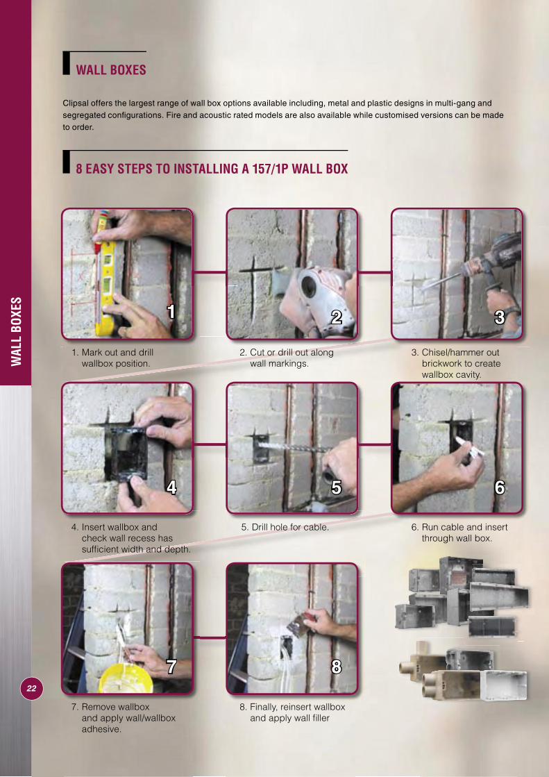
WAL
L BO
XES
1 2 3
4 5 6
7 8
8 EASY STEPS TO INSTALLING A 157/1P WALL BOX
1. Mark out and drill wallbox position.
3. Chisel/hammer out brickwork to create wallbox cavity.
4. Insert wallbox and check wall recess has suffi cient width and depth.
6. Run cable and insert through wall box.
7. Remove wallbox and apply wall/wallbox adhesive.
8. Finally, reinsert wallbox and apply wall fi ller
2. Cut or drill out along wall markings.
5. Drill hole for cable.
WALL BOXES
Clipsal offers the largest range of wall box options available including, metal and plastic designs in multi-gang and segregated confi gurations. Fire and acoustic rated models are also available while customised versions can be made to order.
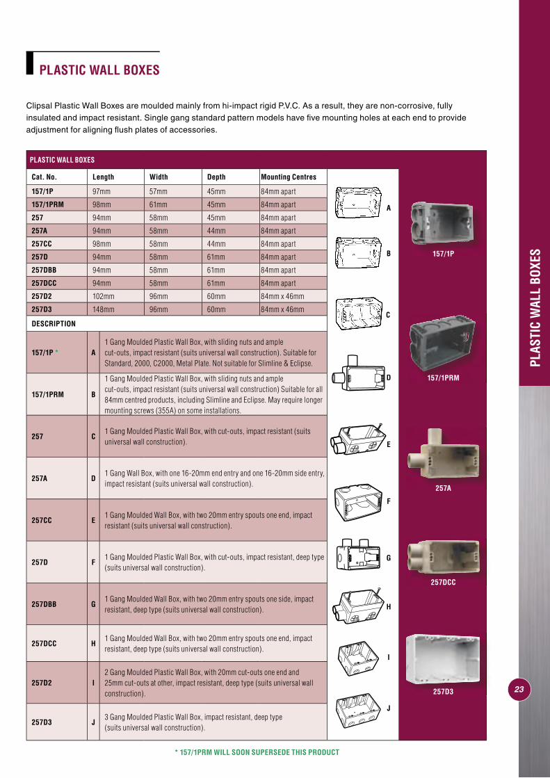
PLASTIC WALL BOXES
Clipsal Plastic Wall Boxes are moulded mainly from hi-impact rigid P.V.C. As a result, they are non-corrosive, fully insulated and impact resistant. Single gang standard pattern models have fi ve mounting holes at each end to provide adjustment for aligning fl ush plates of accessories.
PLASTIC WALL BOXES
Cat. No. Length Width Depth Mounting Centres
157/1P 97mm 57mm 45mm 84mm apart
157/1PRM 98mm 61mm 45mm 84mm apart
257 94mm 58mm 45mm 84mm apart
257A 94mm 58mm 44mm 84mm apart
257CC 98mm 58mm 44mm 84mm apart
257D 94mm 58mm 61mm 84mm apart
257DBB 94mm 58mm 61mm 84mm apart
257DCC 94mm 58mm 61mm 84mm apart
257D2 102mm 96mm 60mm 84mm x 46mm
257D3 148mm 96mm 60mm 84mm x 46mm
DESCRIPTION
157/1P * A1 Gang Moulded Plastic Wall Box, with sliding nuts and ample cut-outs, impact resistant (suits universal wall construction). Suitable for Standard, 2000, C2000, Metal Plate. Not suitable for Slimline & Eclipse.
157/1PRM B
1 Gang Moulded Plastic Wall Box, with sliding nuts and ample cut-outs, impact resistant (suits universal wall construction) Suitable for all 84mm centred products, including Slimline and Eclipse. May require longer mounting screws (355A) on some installations.
257 C1 Gang Moulded Plastic Wall Box, with cut-outs, impact resistant (suits universal wall construction).
257A D1 Gang Wall Box, with one 16-20mm end entry and one 16-20mm side entry, impact resistant (suits universal wall construction).
257CC E1 Gang Moulded Wall Box, with two 20mm entry spouts one end, impact resistant (suits universal wall construction).
257D F1 Gang Moulded Plastic Wall Box, with cut-outs, impact resistant, deep type (suits universal wall construction).
257DBB G1 Gang Moulded Wall Box, with two 20mm entry spouts one side, impact resistant, deep type (suits universal wall construction).
257DCC H1 Gang Moulded Wall Box, with two 20mm entry spouts one end, impact resistant, deep type (suits universal wall construction).
257D2 I2 Gang Moulded Plastic Wall Box, with 20mm cut-outs one end and 25mm cut-outs at other, impact resistant, deep type (suits universal wall construction).
257D3 J3 Gang Moulded Plastic Wall Box, impact resistant, deep type (suits universal wall construction).
F
I
J
A
C
G
E
D
H
B
PLAS
TIC
WAL
L BO
XES
23
* 157/1PRM WILL SOON SUPERSEDE THIS PRODUCT
157/1P
157/1PRM
257A
257DCC
257D3
24
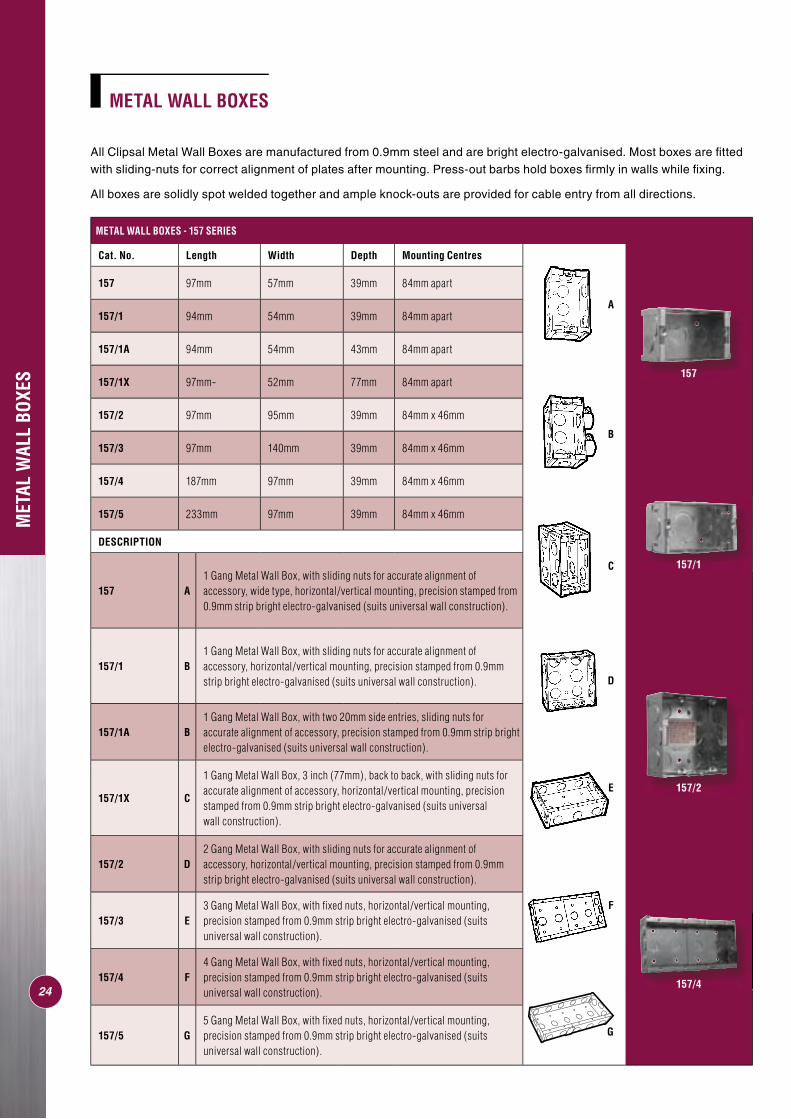
METAL WALL BOXES - 157 SERIES
Cat. No. Length Width Depth Mounting Centres
157 97mm 57mm 39mm 84mm apart
157/1 94mm 54mm 39mm 84mm apart
157/1A 94mm 54mm 43mm 84mm apart
157/1X 97mm- 52mm 77mm 84mm apart
157/2 97mm 95mm 39mm 84mm x 46mm
157/3 97mm 140mm 39mm 84mm x 46mm
157/4 187mm 97mm 39mm 84mm x 46mm
157/5 233mm 97mm 39mm 84mm x 46mm
DESCRIPTION
157 A1 Gang Metal Wall Box, with sliding nuts for accurate alignment of accessory, wide type, horizontal/vertical mounting, precision stamped from 0.9mm strip bright electro-galvanised (suits universal wall construction).
157/1 B1 Gang Metal Wall Box, with sliding nuts for accurate alignment of accessory, horizontal/vertical mounting, precision stamped from 0.9mm strip bright electro-galvanised (suits universal wall construction).
157/1A B1 Gang Metal Wall Box, with two 20mm side entries, sliding nuts for accurate alignment of accessory, precision stamped from 0.9mm strip bright electro-galvanised (suits universal wall construction).
157/1X C
1 Gang Metal Wall Box, 3 inch (77mm), back to back, with sliding nuts for accurate alignment of accessory, horizontal/vertical mounting, precision stamped from 0.9mm strip bright electro-galvanised (suits universal wall construction).
157/2 D2 Gang Metal Wall Box, with sliding nuts for accurate alignment of accessory, horizontal/vertical mounting, precision stamped from 0.9mm strip bright electro-galvanised (suits universal wall construction).
157/3 E3 Gang Metal Wall Box, with fi xed nuts, horizontal/vertical mounting, precision stamped from 0.9mm strip bright electro-galvanised (suits universal wall construction).
157/4 F4 Gang Metal Wall Box, with fi xed nuts, horizontal/vertical mounting, precision stamped from 0.9mm strip bright electro-galvanised (suits universal wall construction).
157/5 G5 Gang Metal Wall Box, with fi xed nuts, horizontal/vertical mounting, precision stamped from 0.9mm strip bright electro-galvanised (suits universal wall construction).
MET
AL W
ALL
BOXE
S
A
B
C
D
E
F
G
METAL WALL BOXES
All Clipsal Metal Wall Boxes are manufactured from 0.9mm steel and are bright electro-galvanised. Most boxes are fi tted with sliding-nuts for correct alignment of plates after mounting. Press-out barbs hold boxes fi rmly in walls while fi xing.
All boxes are solidly spot welded together and ample knock-outs are provided for cable entry from all directions.
157
157/1
157/2
157/4
25
H
D
I
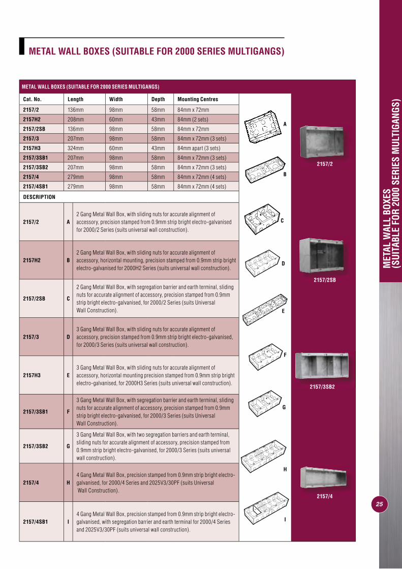
METAL WALL BOXES (SUITABLE FOR 2000 SERIES MULTIGANGS)
Cat. No. Length Width Depth Mounting Centres
2157/2 136mm 98mm 58mm 84mm x 72mm
2157H2 208mm 60mm 43mm 84mm (2 sets)
2157/2SB 136mm 98mm 58mm 84mm x 72mm
2157/3 207mm 98mm 58mm 84mm x 72mm (3 sets)
2157H3 324mm 60mm 43mm 84mm apart (3 sets)
2157/3SB1 207mm 98mm 58mm 84mm x 72mm (3 sets)
2157/3SB2 207mm 98mm 58mm 84mm x 72mm (3 sets)
2157/4 279mm 98mm 58mm 84mm x 72mm (4 sets)
2157/4SB1 279mm 98mm 58mm 84mm x 72mm (4 sets)
DESCRIPTION
2157/2 A2 Gang Metal Wall Box, with sliding nuts for accurate alignment of accessory, precision stamped from 0.9mm strip bright electro-galvanised for 2000/2 Series (suits universal wall construction).
2157H2 B2 Gang Metal Wall Box, with sliding nuts for accurate alignment of accessory, horizontal mounting, precision stamped from 0.9mm strip bright electro-galvanised for 2000H2 Series (suits universal wall construction).
2157/2SB C
2 Gang Metal Wall Box, with segregation barrier and earth terminal, sliding nuts for accurate alignment of accessory, precision stamped from 0.9mm strip bright electro-galvanised, for 2000/2 Series (suits Universal Wall Construction).
2157/3 D3 Gang Metal Wall Box, with sliding nuts for accurate alignment of accessory, precision stamped from 0.9mm strip bright electro-galvanised, for 2000/3 Series (suits universal wall construction).
2157H3 E3 Gang Metal Wall Box, with sliding nuts for accurate alignment of accessory, horizontal mounting precision stamped from 0.9mm strip bright electro-galvanised, for 2000H3 Series (suits universal wall construction).
2157/3SB1 F
3 Gang Metal Wall Box, with segregation barrier and earth terminal, sliding nuts for accurate alignment of accessory, precision stamped from 0.9mm strip bright electro-galvanised, for 2000/3 Series (suits Universal Wall Construction).
2157/3SB2 G
3 Gang Metal Wall Box, with two segregation barriers and earth terminal, sliding nuts for accurate alignment of accessory, precision stamped from 0.9mm strip bright electro-galvanised, for 2000/3 Series (suits universal wall construction).
2157/4 H4 Gang Metal Wall Box, precision stamped from 0.9mm strip bright electro-galvanised, for 2000/4 Series and 2025V3/30PF (suits Universal Wall Construction).
2157/4SB1 I4 Gang Metal Wall Box, precision stamped from 0.9mm strip bright electro-galvanised, with segregation barrier and earth terminal for 2000/4 Series and 2025V3/30PF (suits universal wall construction).
MET
AL W
ALL
BOXE
S (S
UITA
BLE
FOR
2000
SER
IES
MUL
TIGA
NGS)
A
B
E
C
G
F
METAL WALL BOXES (SUITABLE FOR 2000 SERIES MULTIGANGS)
2157/2
2157/2SB
2157/3SB2
2157/4
26
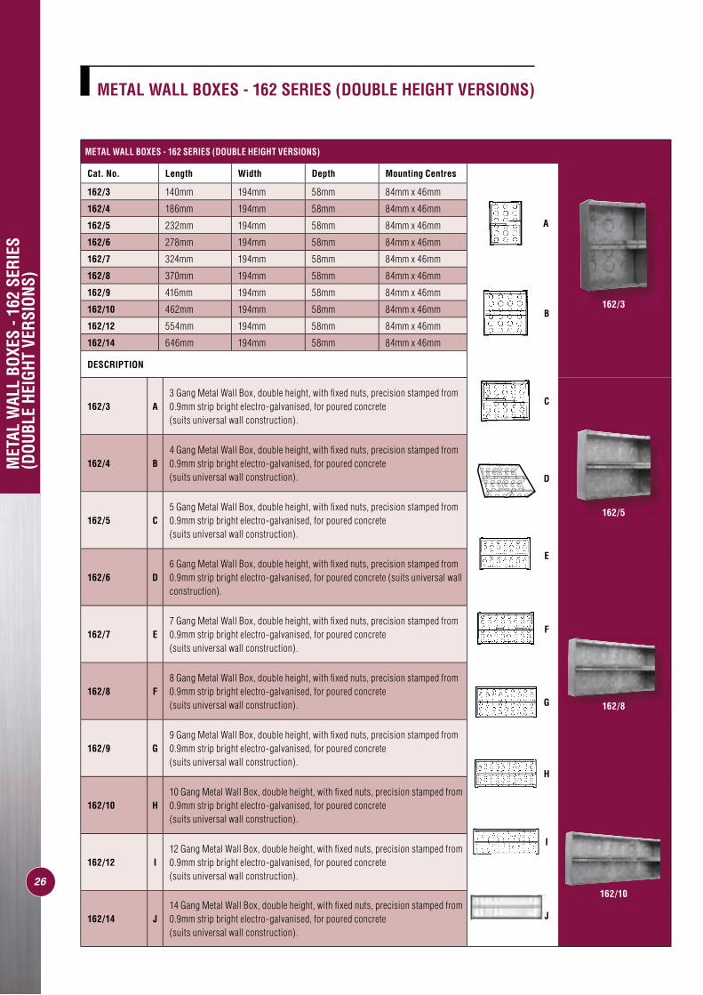
162/3 A3 Gang Metal Wall Box, double height, with fi xed nuts, precision stamped from 0.9mm strip bright electro-galvanised, for poured concrete (suits universal wall construction).
162/4 B4 Gang Metal Wall Box, double height, with fi xed nuts, precision stamped from 0.9mm strip bright electro-galvanised, for poured concrete (suits universal wall construction).
162/5 C5 Gang Metal Wall Box, double height, with fi xed nuts, precision stamped from 0.9mm strip bright electro-galvanised, for poured concrete (suits universal wall construction).
162/6 D6 Gang Metal Wall Box, double height, with fi xed nuts, precision stamped from 0.9mm strip bright electro-galvanised, for poured concrete (suits universal wall construction).
162/7 E7 Gang Metal Wall Box, double height, with fi xed nuts, precision stamped from 0.9mm strip bright electro-galvanised, for poured concrete (suits universal wall construction).
162/8 F8 Gang Metal Wall Box, double height, with fi xed nuts, precision stamped from 0.9mm strip bright electro-galvanised, for poured concrete (suits universal wall construction).
162/9 G9 Gang Metal Wall Box, double height, with fi xed nuts, precision stamped from 0.9mm strip bright electro-galvanised, for poured concrete (suits universal wall construction).
162/10 H10 Gang Metal Wall Box, double height, with fi xed nuts, precision stamped from 0.9mm strip bright electro-galvanised, for poured concrete (suits universal wall construction).
162/12 I12 Gang Metal Wall Box, double height, with fi xed nuts, precision stamped from 0.9mm strip bright electro-galvanised, for poured concrete (suits universal wall construction).
162/14 J14 Gang Metal Wall Box, double height, with fi xed nuts, precision stamped from 0.9mm strip bright electro-galvanised, for poured concrete (suits universal wall construction).
METAL WALL BOXES - 162 SERIES (DOUBLE HEIGHT VERSIONS)
Cat. No. Length Width Depth Mounting Centres
162/3 140mm 194mm 58mm 84mm x 46mm
162/4 186mm 194mm 58mm 84mm x 46mm
162/5 232mm 194mm 58mm 84mm x 46mm
162/6 278mm 194mm 58mm 84mm x 46mm
162/7 324mm 194mm 58mm 84mm x 46mm
162/8 370mm 194mm 58mm 84mm x 46mm
162/9 416mm 194mm 58mm 84mm x 46mm
162/10 462mm 194mm 58mm 84mm x 46mm
162/12 554mm 194mm 58mm 84mm x 46mm
162/14 646mm 194mm 58mm 84mm x 46mm
DESCRIPTION
MET
AL W
ALL
BOXE
S - 1
62 S
ERIE
S (D
OUBL
E HE
IGHT
VER
SION
S)
A
B
C
D
E
F
G
H
I
J
METAL WALL BOXES - 162 SERIES (DOUBLE HEIGHT VERSIONS)
162/3
162/5
162/8
162/10
27
MET
AL W
ALL
BOXE
S - 1
63,1
60 A
ND 1
64 S
ERIE
S(T
RIPL
E AN
D SI
NGLE
HEI
GHT
VERS
IONS
)
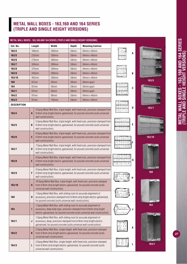
METAL WALL BOXES - 163,160 AND 164 SERIES (TRIPLE AND SINGLE HEIGHT VERSIONS)
Cat. No. Length Width Depth Mounting Centres
163/4 189mm 289mm 58mm 84mm x 46mm
163/5 235mm 289mm 58mm 84mm x 46mm
163/6 278mm 289mm 58mm 84mm x 46mm
163/7 324mm 289mm 58mm 84mm x 46mm
163/8 370mm 289mm 58mm 84mm x 46mm
163/9 416mm 289mm 58mm 84mm x 46mm
163/10 462mm 289mm 58mm 84mm x 46mm
160 97mm 50mm 39mm 84mm apart
164 97mm 56mm 58mm 84mm apart
164/1 97mm 50mm 58mm 84mm apart
164/2 97mm 96mm 58mm 84mm x 46mm
164/3 97mm 142mm 58mm 84mm x 46mm
DESCRIPTION
163/4 A4 Gang Metal Wall Box, triple height, with fi xed nuts, precision stamped from 0.9mm strip bright electro-galvanised, for poured concrete (suits universal wall construction).
163/5 B5 Gang Metal Wall Box, triple height, with fi xed nuts, precision stamped from 0.9mm strip bright electro-galvanised, for poured concrete (suits universal wall construction).
163/6 C6 Gang Metal Wall Box, triple height, with fi xed nuts, precision stamped from 0.9mm strip bright electro-galvanised, for poured concrete (suits universal wall construction).
163/7 D7 Gang Metal Wall Box, triple height, with fi xed nuts, precision stamped from 0.9mm strip bright electro-galvanised, for poured concrete (suits universal wall construction).
163/8 E8 Gang Metal Wall Box, triple height, with fi xed nuts, precision stamped from 0.9mm strip bright electro-galvanised, for poured concrete (suits universal wall construction).
163/9 F9 Gang Metal Wall Box, triple height, with fi xed nuts, precision stamped from 0.9mm strip bright electro-galvanised, for poured concrete (suits universal wall construction).
163/10 G10 Gang Metal Wall Box, triple height, with fi xed nuts, precision stamped from 0.9mm strip bright electro-galvanised, for poured concrete (suits universal wall construction).
160 H1 Gang Metal Wall Box, with sliding nuts for accurate alignment of accessory, precision stamped from 0.9mm strip bright electro-galvanised, for poured concrete (suits universal wall construction).
164 I1 Gang Metal Wall Box, with sliding nuts for accurate alignment of accessory, deep wide type, precision stamped from 0.9mm strip bright electro-galvanised, for poured concrete (suits universal wall construction).
164/1 J1 Gang Metal Wall Box, with sliding nuts for accurate alignment of accessory, deep, precision stamped from 0.9mm strip bright electro-galvanised, for poured concrete (suits universal wall construction).
164/2 K2 Gang Metal Wall Box, single height, with fi xed nuts, precision stamped from 0.9mm strip bright electro-galvanised, for poured concrete (suits universal wall construction).
164/3 L3 Gang Metal Wall Box, single height, with fi xed nuts, precision stamped from 0.9mm strip bright electro-galvanised, for poured concrete (suits universal wall construction).
A
G
D
E
J
I
K
L
B
C
H
F
METAL WALL BOXES - 163,160 AND 164 SERIES (TRIPLE AND SINGLE HEIGHT VERSIONS)
163/5
163/7
163/10
160
164
164/1
I
H
G
F
28
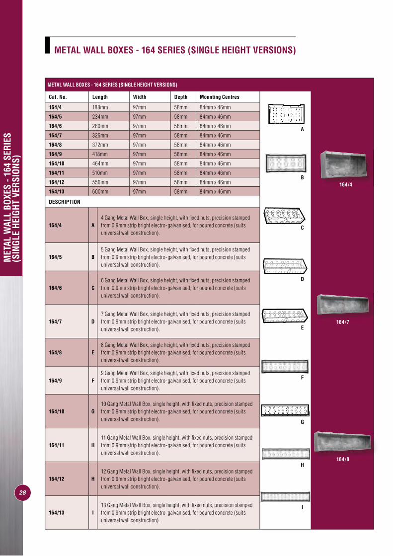
METAL WALL BOXES - 164 SERIES (SINGLE HEIGHT VERSIONS)
Cat. No. Length Width Depth Mounting Centres
164/4 188mm 97mm 58mm 84mm x 46mm
164/5 234mm 97mm 58mm 84mm x 46mm
164/6 280mm 97mm 58mm 84mm x 46mm
164/7 326mm 97mm 58mm 84mm x 46mm
164/8 372mm 97mm 58mm 84mm x 46mm
164/9 418mm 97mm 58mm 84mm x 46mm
164/10 464mm 97mm 58mm 84mm x 46mm
164/11 510mm 97mm 58mm 84mm x 46mm
164/12 556mm 97mm 58mm 84mm x 46mm
164/13 600mm 97mm 58mm 84mm x 46mm
DESCRIPTION
164/4 A4 Gang Metal Wall Box, single height, with fi xed nuts, precision stamped from 0.9mm strip bright electro-galvanised, for poured concrete (suits universal wall construction).
164/5 B5 Gang Metal Wall Box, single height, with fi xed nuts, precision stamped from 0.9mm strip bright electro-galvanised, for poured concrete (suits universal wall construction).
164/6 C6 Gang Metal Wall Box, single height, with fi xed nuts, precision stamped from 0.9mm strip bright electro-galvanised, for poured concrete (suits universal wall construction).
164/7 D7 Gang Metal Wall Box, single height, with fi xed nuts, precision stamped from 0.9mm strip bright electro-galvanised, for poured concrete (suits universal wall construction).
164/8 E8 Gang Metal Wall Box, single height, with fi xed nuts, precision stamped from 0.9mm strip bright electro-galvanised, for poured concrete (suits universal wall construction).
164/9 F9 Gang Metal Wall Box, single height, with fi xed nuts, precision stamped from 0.9mm strip bright electro-galvanised, for poured concrete (suits universal wall construction).
164/10 G10 Gang Metal Wall Box, single height, with fi xed nuts, precision stamped from 0.9mm strip bright electro-galvanised, for poured concrete (suits universal wall construction).
164/11 H11 Gang Metal Wall Box, single height, with fi xed nuts, precision stamped from 0.9mm strip bright electro-galvanised, for poured concrete (suits universal wall construction).
164/12 H12 Gang Metal Wall Box, single height, with fi xed nuts, precision stamped from 0.9mm strip bright electro-galvanised, for poured concrete (suits universal wall construction).
164/13 I13 Gang Metal Wall Box, single height, with fi xed nuts, precision stamped from 0.9mm strip bright electro-galvanised, for poured concrete (suits universal wall construction).
MET
AL W
ALL
BOXE
S - 1
64 S
ERIE
S (S
INGL
E HE
IGHT
VER
SION
S)
A
B
C
D
E
METAL WALL BOXES - 164 SERIES (SINGLE HEIGHT VERSIONS)
164/4
164/7
164/8
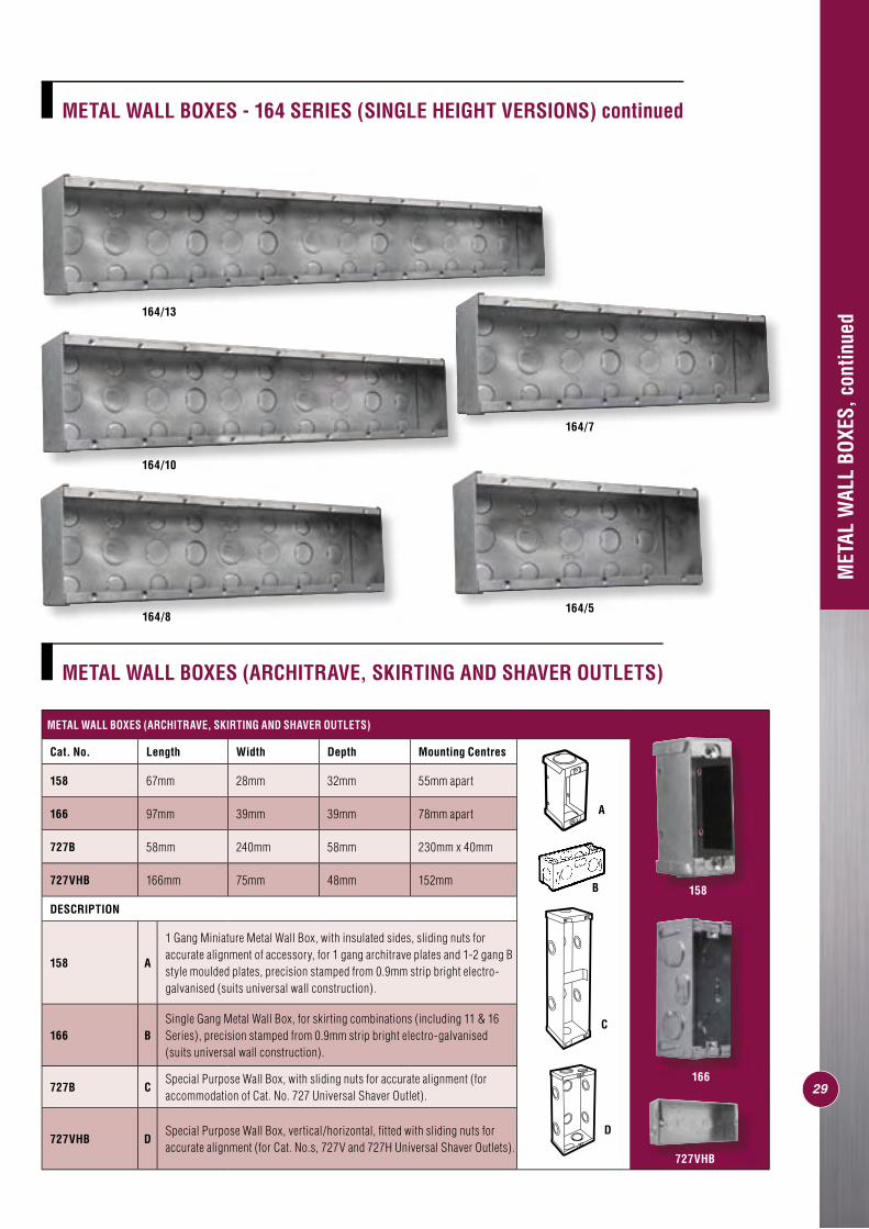
METAL WALL BOXES (ARCHITRAVE, SKIRTING AND SHAVER OUTLETS)
Cat. No. Length Width Depth Mounting Centres
158 67mm 28mm 32mm 55mm apart
166 97mm 39mm 39mm 78mm apart
727B 58mm 240mm 58mm 230mm x 40mm
727VHB 166mm 75mm 48mm 152mm
DESCRIPTION
158 A
1 Gang Miniature Metal Wall Box, with insulated sides, sliding nuts for accurate alignment of accessory, for 1 gang architrave plates and 1-2 gang B style moulded plates, precision stamped from 0.9mm strip bright electro-galvanised (suits universal wall construction).
166 BSingle Gang Metal Wall Box, for skirting combinations (including 11 & 16 Series), precision stamped from 0.9mm strip bright electro-galvanised (suits universal wall construction).
727B CSpecial Purpose Wall Box, with sliding nuts for accurate alignment (for accommodation of Cat. No. 727 Universal Shaver Outlet).
727VHB DSpecial Purpose Wall Box, vertical/horizontal, fi tted with sliding nuts for accurate alignment (for Cat. No.s, 727V and 727H Universal Shaver Outlets).
C
D
B
A
29
MET
AL W
ALL
BOXE
S, c
ontin
ued
METAL WALL BOXES (ARCHITRAVE, SKIRTING AND SHAVER OUTLETS)
METAL WALL BOXES - 164 SERIES (SINGLE HEIGHT VERSIONS) continued
158
166
727VHB
164/13
164/10
164/8164/5
164/7
30
FIRE
AND
ACO
USTI
CALL
Y RA
TED
WAL
L BO
XES
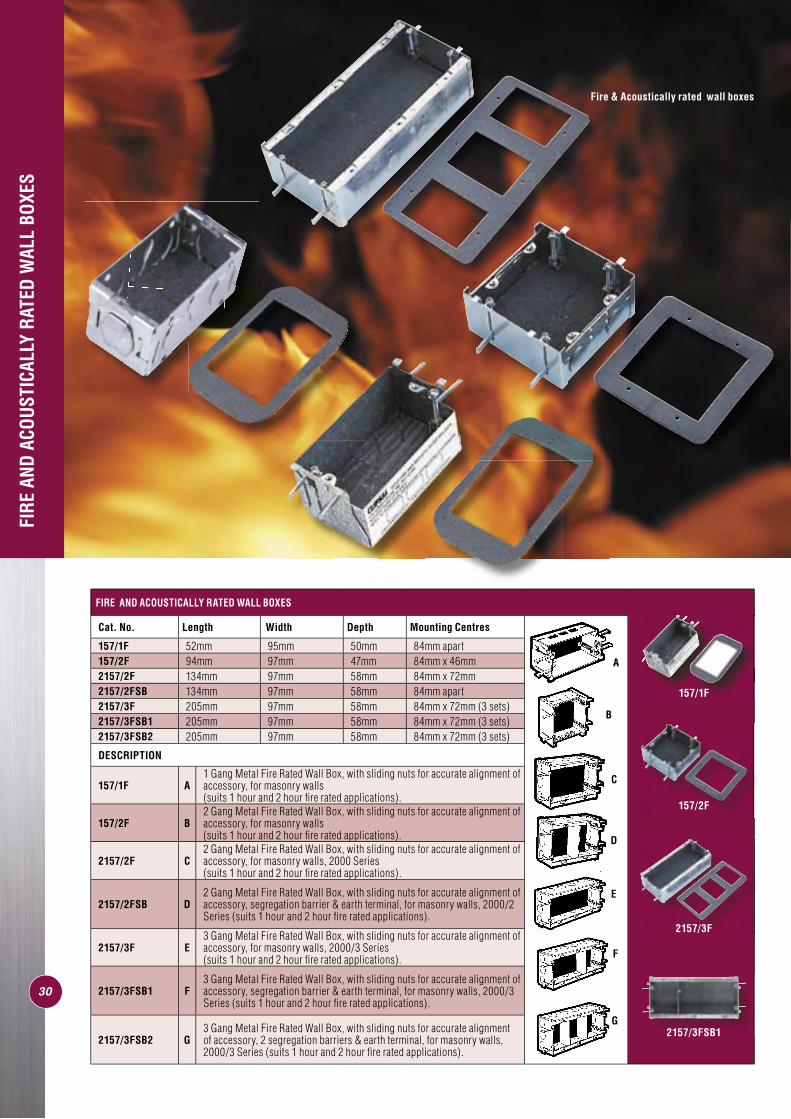
Fire & Acoustically rated wall boxes
FIRE AND ACOUSTICALLY RATED WALL BOXES
Cat. No. Length Width Depth Mounting Centres
157/1F 52mm 95mm 50mm 84mm apart157/2F 94mm 97mm 47mm 84mm x 46mm2157/2F 134mm 97mm 58mm 84mm x 72mm2157/2FSB 134mm 97mm 58mm 84mm apart2157/3F 205mm 97mm 58mm 84mm x 72mm (3 sets)2157/3FSB1 205mm 97mm 58mm 84mm x 72mm (3 sets)2157/3FSB2 205mm 97mm 58mm 84mm x 72mm (3 sets)
DESCRIPTION
157/1F A1 Gang Metal Fire Rated Wall Box, with sliding nuts for accurate alignment of accessory, for masonry walls (suits 1 hour and 2 hour fi re rated applications).
157/2F B2 Gang Metal Fire Rated Wall Box, with sliding nuts for accurate alignment of accessory, for masonry walls (suits 1 hour and 2 hour fi re rated applications).
2157/2F C2 Gang Metal Fire Rated Wall Box, with sliding nuts for accurate alignment of accessory, for masonry walls, 2000 Series (suits 1 hour and 2 hour fi re rated applications).
2157/2FSB D2 Gang Metal Fire Rated Wall Box, with sliding nuts for accurate alignment of accessory, segregation barrier & earth terminal, for masonry walls, 2000/2 Series (suits 1 hour and 2 hour fi re rated applications).
2157/3F E3 Gang Metal Fire Rated Wall Box, with sliding nuts for accurate alignment of accessory, for masonry walls, 2000/3 Series (suits 1 hour and 2 hour fi re rated applications).
2157/3FSB1 F3 Gang Metal Fire Rated Wall Box, with sliding nuts for accurate alignment of accessory, segregation barrier & earth terminal, for masonry walls, 2000/3 Series (suits 1 hour and 2 hour fi re rated applications).
2157/3FSB2 G3 Gang Metal Fire Rated Wall Box, with sliding nuts for accurate alignment of accessory, 2 segregation barriers & earth terminal, for masonry walls, 2000/3 Series (suits 1 hour and 2 hour fi re rated applications).
A
E
F
G
B
C
D
157/1F
157/2F
2157/3F
2157/3FSB1
FIRE
AND
ACO
USTI
CALL
Y RA
TED
WAL
L BO
XES,
CON
TINU
ED
31
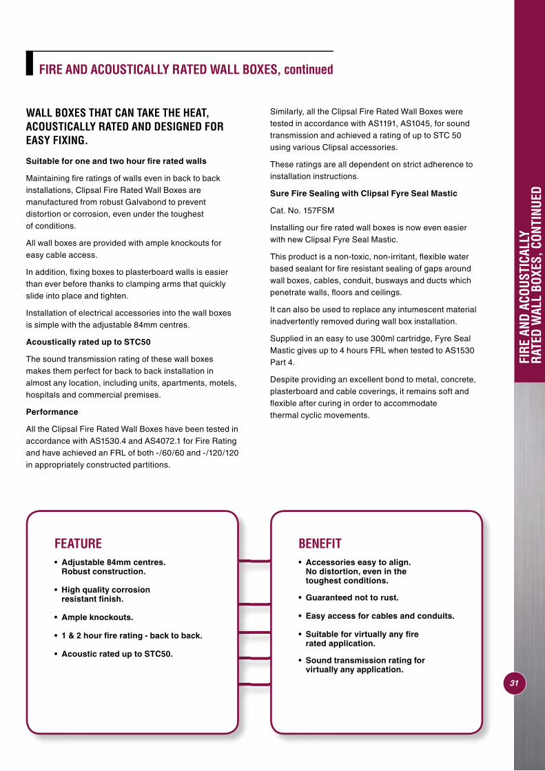
FIRE AND ACOUSTICALLY RATED WALL BOXES, continued
WALL BOXES THAT CAN TAKE THE HEAT, ACOUSTICALLY RATED AND DESIGNED FOR EASY FIXING.
Suitable for one and two hour fi re rated walls
Maintaining fi re ratings of walls even in back to back installations, Clipsal Fire Rated Wall Boxes are manufactured from robust Galvabond to prevent distortion or corrosion, even under the toughest of conditions.
All wall boxes are provided with ample knockouts for easy cable access.
In addition, fi xing boxes to plasterboard walls is easier than ever before thanks to clamping arms that quickly slide into place and tighten.
Installation of electrical accessories into the wall boxes is simple with the adjustable 84mm centres.
Acoustically rated up to STC50
The sound transmission rating of these wall boxes makes them perfect for back to back installation in almost any location, including units, apartments, motels, hospitals and commercial premises.
Performance
All the Clipsal Fire Rated Wall Boxes have been tested in accordance with AS1530.4 and AS4072.1 for Fire Rating and have achieved an FRL of both -/60/60 and -/120/120 in appropriately constructed partitions.
Similarly, all the Clipsal Fire Rated Wall Boxes were tested in accordance with AS1191, AS1045, for sound transmission and achieved a rating of up to STC 50 using various Clipsal accessories.
These ratings are all dependent on strict adherence toinstallation instructions.
Sure Fire Sealing with Clipsal Fyre Seal Mastic
Cat. No. 157FSM
Installing our fi re rated wall boxes is now even easier with new Clipsal Fyre Seal Mastic.
This product is a non-toxic, non-irritant, fl exible water based sealant for fi re resistant sealing of gaps around wall boxes, cables, conduit, busways and ducts which penetrate walls, fl oors and ceilings.
It can also be used to replace any intumescent material inadvertently removed during wall box installation.
Supplied in an easy to use 300ml cartridge, Fyre Seal Mastic gives up to 4 hours FRL when tested to AS1530 Part 4.
Despite providing an excellent bond to metal, concrete, plasterboard and cable coverings, it remains soft and fl exible after curing in order to accommodatethermal cyclic movements.
FEATURE• Adjustable 84mm centres. Robust construction.
• High quality corrosion resistant fi nish.
• Ample knockouts.
• 1 & 2 hour fi re rating - back to back.
• Acoustic rated up to STC50.
BENEFIT• Accessories easy to align. No distortion, even in the toughest conditions.
• Guaranteed not to rust.
• Easy access for cables and conduits.
• Suitable for virtually any fi re rated application.
• Sound transmission rating for virtually any application.
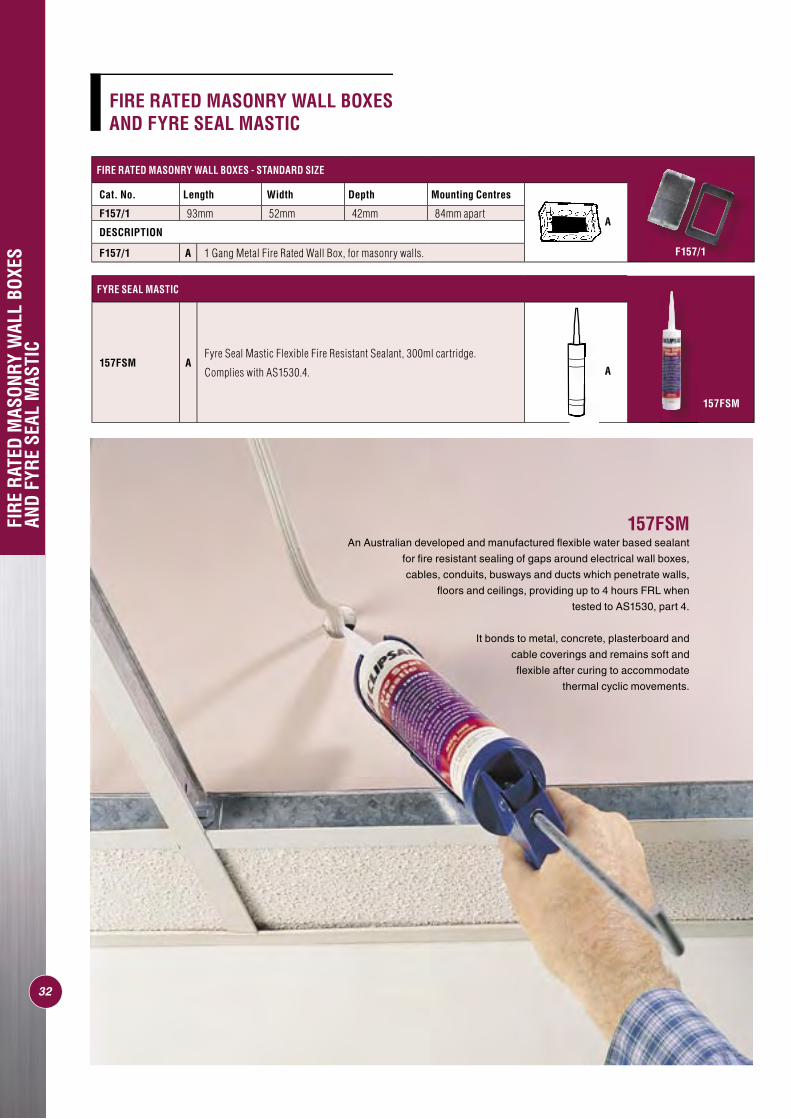
FIRE RATED MASONRY WALL BOXES - STANDARD SIZE
Cat. No. Length Width Depth Mounting Centres
F157/1 93mm 52mm 42mm 84mm apart
DESCRIPTION
F157/1 A 1 Gang Metal Fire Rated Wall Box, for masonry walls.
FYRE SEAL MASTIC
157FSM AFyre Seal Mastic Flexible Fire Resistant Sealant, 300ml cartridge.
Complies with AS1530.4.
FIRE
RAT
ED M
ASON
RY W
ALL
BOXE
S AN
D FY
RE S
EAL
MAS
TIC
32
A
A
F157/1
157FSM
157FSMAn Australian developed and manufactured fl exible water based sealant
for fi re resistant sealing of gaps around electrical wall boxes,
cables, conduits, busways and ducts which penetrate walls,
fl oors and ceilings, providing up to 4 hours FRL when
tested to AS1530, part 4.
It bonds to metal, concrete, plasterboard and
cable coverings and remains soft and
fl exible after curing to accommodate
thermal cyclic movements.
FIRE RATED MASONRY WALL BOXES AND FYRE SEAL MASTIC
1 2 3
4 5 6
7 8
33
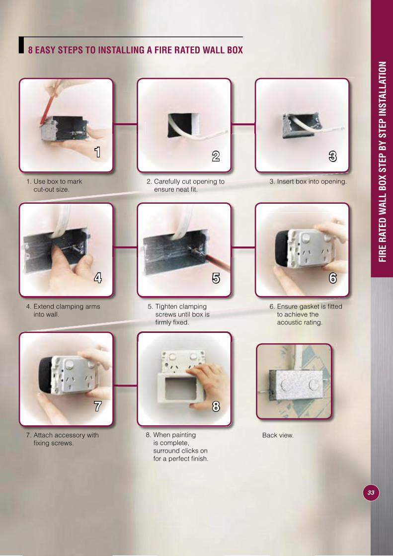
8 EASY STEPS TO INSTALLING A FIRE RATED WALL BOX
1. Use box to mark cut-out size.
3. Insert box into opening.
4. Extend clamping arms into wall.
6. Ensure gasket is fi tted to achieve the acoustic rating.
7. Attach accessory with fi xing screws.
8. When painting is complete, surround clicks on for a perfect fi nish.
2. Carefully cut opening to ensure neat fi t.
5. Tighten clamping screws until box is fi rmly fi xed.
Back view.
FIRE
RAT
ED W
ALL
BOX
STEP
BY
STEP
INST
ALLA
TION
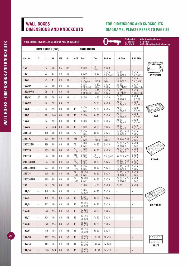
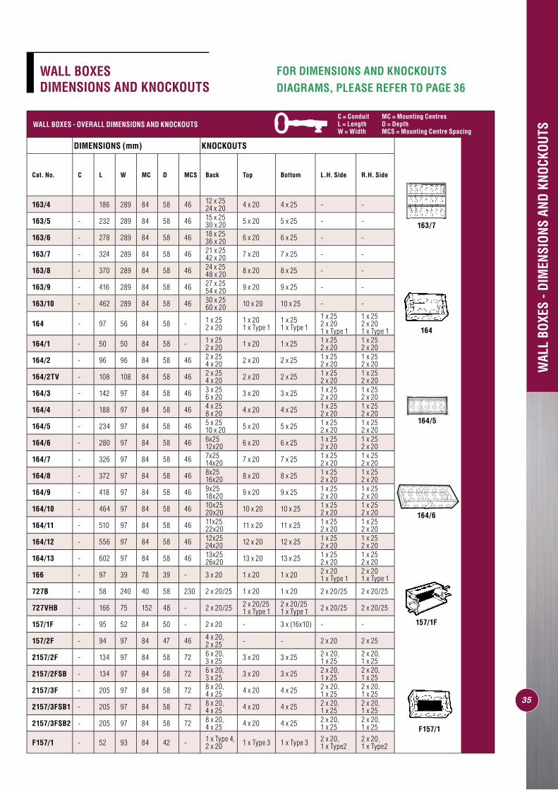
FOR DIMENSIONS AND KNOCKOUTS DIAGRAMS, PLEASE REFER TO PAGE 36
34
WALL BOXES - OVERALL DIMENSIONS AND KNOCKOUTS
DIMENSIONS (mm) KNOCKOUTS
Cat. No. C L W MC D MCS Back Top Bottom L.H. Side R.H. Side
158 - 67 28 55 32 - 1 x 20 1 x Type 1 1 x 20 - -
157 - 97 57 84 39 - 3 x 20 1 x 20 1 x 201 x Type 1
2 x 201 x Type 1
2 x 201 x Type 1
157/1 - 94 54 84 43 -2 x 2 0 1 x Type 4
1 x Type 3
1 x Type 3
2 x 201 x Type 2
2 x 201 x Type 2
157/1P - 97 60 84 45 - 1 x 25, 1 x (35SQ.)
1 x 20, 1x 25
1 x 20, 1 x 25
2 x 25, 1 x (24x14)
2 x 25, 1 x (24x14)
157/1PRM - 98 61 84 45 - 1 x 25, 1 x (35SQ.)
1 x 20, 1x 25
1 x 20, 1 x 25
2 x 25, 1 x (24x14)
2 x 25, 1 x (24x14)
157/1C 20 97 50 84 39 - 3 x 20 1 x 20 1 x 20 2 x 201 x Type 1
2 x 201 x Type 1
157/1X - 97 52 84 77 - - 2 x 20 2 x 20 2 x 20 1 x Type 1
2 x 201 x Type 1
157/2 - 97 95 84 39 464 x 202 x 25
2 x 20 2 x 25 2 x 201 x Type 1
2 x 201 x Type 1
157/3 - 97 140 84 39 46 3 x 20 3 x 20 3 x 25 2 x 201 x Type 1
2 x 201 x Type 1
157/4 - 97 187 84 39 46 4 x 20 4 x 20 4 x 25 2 x 201 x Type 1
2 x 201 x Type 1
157/ 5 - 97 233 84 39 46 5 x 20 5 x 20 5 x 25 2 x 201 x Type 1
2 x 201 x Type 1
2157/2 - 136 96 84 58 72 6 x 20, 3 x 25 3 x 20 3 x 25 2 x 20, 1 x 25,
1 x Type 12 x 20, 1 x 25
2157H2 - 208 60 84 43 116 2 x 32, 2 x 20
1 x Type 3
1 x Type 3 4 x 20, 2 x 25 4 x 20,
2 x 25
2157/2SB - 136 98 84 58 72 6 x 20, 3 x 25 3 x 20 3 x 25 2 x 20, 1 x 25,
1 x Type 12 x 20, 1 x 25
2157/3 - 205 96 84 58 72 (x2)
8 x 20, 4 x 25 4 x 20 4 x 25 2 x 20, 1 x 25,
1 x Type 12 x 20, 1 x 25
2157H3 - 324 60 84 43 116 (x2)
3 x 32, 3 x 20
1 x Type 3 1 x Type 3 6 x 20, 3 x 25 6 x 20,
3 x 25
2157/3SB1 - 207 98 84 58 72 (x2)
8 x 20, 4 x 25 4 x 20 4 x 25 2 x 20, 1 x 25,
1 x Type 12 x 20, 1 x 25
2157/3SB2 - 207 98 84 58 72 (x2)
8 x 20, 4 x 25 4 x 20 4 x 25 2 x 20, 1 x 25,
1 x Type 12 x 20, 1 x 25
2157/4 - 279 98 84 58 72 (x3)
12 x 20, 6 x 25 6 x 20 6 x 25 2 x 20, 1 x 25,
1 x Type 12 x 20, 1 x 25
2157/4SB1 - 279 98 84 58 72 (x3)
12 x 20, 6 x 25 6 x 20 6 x 25 2 x 20, 1 x 25,
1 x Type 12 x 20, 1 x 25
160 - 97 50 84 39 - 3 x 20 1 x 20 1 x 20 2 x 20 2 x 20
162/3 - 140 194 84 58 - 6 x 2512 x 20 3 x 20 3 x 25 - -
162/4 - 186 194 84 58 46 8 x 2516 x 20 4 x 20 4 x 25 - -
162/5 - 232 194 84 58 46 10 x 2520 x 20 5 x 20 5 x 25 - -
162/6 - 278 194 84 58 46 12 x 2524 x 20 6 x 20 6 x 25 - -
162/7 - 324 194 84 58 46 14 x 2528 x 20 7 x 20 7 x 25 - -
162/8 - 370 194 84 58 46 16 x 2532 x 20 8 x 20 8 x 25 - -
162/9 - 416 194 84 58 46 18 x 2536 x 20 9 x 20 9 x 25 - -
162/10 - 462 194 84 58 46 20 x 2540 x 20 10 x 20 10 x 25 - -
162/12 - 554 194 84 58 46 24 x 2548 x 20 12 x 20 12 x 25 - -
162/14 - 646 646 84 58 46 28 x 2556 x 20 14 x 20 14 x 25 - -
WAL
L BO
XES
- DIM
ENSI
ONS
AND
KNOC
KOUT
S
WALL BOXES DIMENSIONS AND KNOCKOUTS
C = Conduit MC = Mounting CentresL = Length D = DepthW = Width MCS = Mounting Centre Spacing
157/1PRM
157/5
2157/3
2157/4SB1
162/7
FOR DIMENSIONS AND KNOCKOUTS DIAGRAMS, PLEASE REFER TO PAGE 36
35
WAL
L BO
XES
- DIM
ENSI
ONS
AND
KNOC
KOUT
SWALL BOXES - OVERALL DIMENSIONS AND KNOCKOUTS
DIMENSIONS (mm) KNOCKOUTS
Cat. No. C L W MC D MCS Back Top Bottom L.H. Side R.H. Side
163/4 186 289 84 58 46 12 x 2524 x 20 4 x 20 4 x 25 - -
163/5 - 232 289 84 58 46 15 x 2530 x 20 5 x 20 5 x 25 - -
163/6 - 278 289 84 58 46 18 x 2536 x 20 6 x 20 6 x 25 - -
163/7 - 324 289 84 58 46 21 x 2542 x 20 7 x 20 7 x 25 - -
163/8 - 370 289 84 58 46 24 x 2548 x 20 8 x 20 8 x 25 - -
163/9 - 416 289 84 58 46 27 x 2554 x 20 9 x 20 9 x 25 - -
163/10 - 462 289 84 58 46 30 x 2560 x 20 10 x 20 10 x 25 - -
164 - 97 56 84 58 - 1 x 252 x 20
1 x 201 x Type 1
1 x 251 x Type 1
1 x 252 x 201 x Type 1
1 x 252 x 201 x Type 1
164/1 - 50 50 84 58 - 1 x 252 x 20 1 x 20 1 x 25 1 x 25
2 x 201 x 252 x 20
164/2 - 96 96 84 58 46 2 x 254 x 20 2 x 20 2 x 25 1 x 25
2 x 201 x 252 x 20
164/2TV - 108 108 84 58 46 2 x 254 x 20 2 x 20 2 x 25 1 x 25
2 x 201 x 252 x 20
164/3 - 142 97 84 58 46 3 x 256 x 20 3 x 20 3 x 25 1 x 25
2 x 201 x 252 x 20
164/4 - 188 97 84 58 46 4 x 258 x 20 4 x 20 4 x 25 1 x 25
2 x 201 x 252 x 20
164/5 - 234 97 84 58 46 5 x 2510 x 20 5 x 20 5 x 25 1 x 25
2 x 201 x 252 x 20
164/6 - 280 97 84 58 46 6x2512x20 6 x 20 6 x 25 1 x 25
2 x 201 x 252 x 20
164/7 - 326 97 84 58 46 7x2514x20 7 x 20 7 x 25 1 x 25
2 x 201 x 252 x 20
164/8 - 372 97 84 58 46 8x2516x20 8 x 20 8 x 25 1 x 25
2 x 201 x 252 x 20
164/9 - 418 97 84 58 46 9x2518x20 9 x 20 9 x 25 1 x 25
2 x 201 x 252 x 20
164/10 - 464 97 84 58 46 10x2520x20 10 x 20 10 x 25 1 x 25
2 x 201 x 252 x 20
164/11 - 510 97 84 58 46 11x2522x20 11 x 20 11 x 25 1 x 25
2 x 201 x 252 x 20
164/12 - 556 97 84 58 46 12x2524x20 12 x 20 12 x 25 1 x 25
2 x 201 x 252 x 20
164/13 - 602 97 84 58 46 13x2526x20 13 x 20 13 x 25 1 x 25
2 x 201 x 252 x 20
166 - 97 39 78 39 - 3 x 20 1 x 20 1 x 20 2 x 201 x Type 1
2 x 201 x Type 1
727B - 58 240 40 58 230 2 x 20/25 1 x 20 1 x 20 2 x 20/25 2 x 20/25
727VHB - 166 75 152 48 - 2 x 20/25 2 x 20/251 x Type 1
2 x 20/251 x Type 1 2 x 20/25 2 x 20/25
157/1F - 95 52 84 50 - 2 x 20 - 3 x (16x10) - -
157/2F - 94 97 84 47 46 4 x 20, 2 x 25 - - 2 x 20 2 x 25
2157/2F - 134 97 84 58 72 6 x 20, 3 x 25 3 x 20 3 x 25 2 x 20,
1 x 252 x 20, 1 x 25
2157/2FSB - 134 97 84 58 72 6 x 20, 3 x 25 3 x 20 3 x 25 2 x 20,
1 x 252 x 20, 1 x 25
2157/3F - 205 97 84 58 72 8 x 20, 4 x 25 4 x 20 4 x 25 2 x 20,
1 x 252 x 20, 1 x 25
2157/3FSB1 - 205 97 84 58 72 8 x 20, 4 x 25 4 x 20 4 x 25 2 x 20,
1 x 252 x 20, 1 x 25
2157/3FSB2 - 205 97 84 58 72 8 x 20, 4 x 25 4 x 20 4 x 25 2 x 20,
1 x 252 x 20, 1 x 25
F157/1 - 52 93 84 42 - 1 x Type 4, 2 x 20 1 x Type 3 1 x Type 3 2 x 20,
1 x Type22 x 20, 1 x Type2
C = Conduit MC = Mounting CentresL = Length D = DepthW = Width MCS = Mounting Centre Spacing
WALL BOXES DIMENSIONS AND KNOCKOUTS
C = Conduit MC = Mounting CentresL = Length D = DepthW = Width MCS = Mounting Centre Spacing
164/5
164
163/7
157/1F
164/6
F157/1
MCS
L
C
W
D
MC
L.HSIDE
R.HSIDE
TOP
BOTTOM
MCS
36
MET
AL W
ALL
BOXE
S, D
IMEN
SION
AL D
ETAI
L
METAL WALL BOXES, DIMENSIONAL DETAIL
C = Conduit MC = Mounting CentresL = Length D = DepthW = Width MCS = Mounting Centre Spacing
37
SURF
ACE
ENCL
OSUR
ES A
ND B
OXES
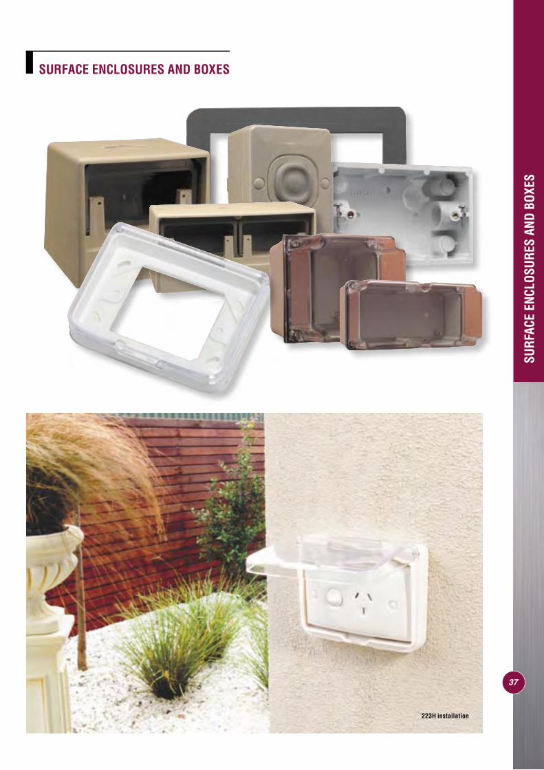
SURFACE ENCLOSURES AND BOXES
C = Conduit MC = Mounting CentresL = Length D = DepthW = Width MCS = Mounting Centre Spacing
223H installation
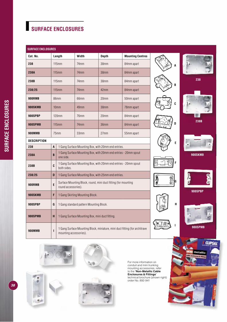
SURFACE ENCLOSURES
Cat. No. Length Width Depth Mounting Centres
238 115mm 74mm 38mm 84mm apart
238A 115mm 74mm 38mm 84mm apart
238B 115mm 74mm 38mm 84mm apart
238/25 115mm 74mm 42mm 84mm apart
900RMB 86mm 66mm 20mm 50mm apart
900SKMB 10mm 49mm 38mm 78mm apart
900SPBP 120mm 76mm 20mm 84mm apart
900SPMB 115mm 74mm 36mm 84mm apart
900MMB 75mm 33mm 27mm 55mm apart
DESCRIPTION
238 A 1 Gang Surface Mounting Box, with 20mm end entries.
238A B1 Gang Surface Mounting Box, with 20mm end entries - 20mm spout one side.
238B C1 Gang Surface Mounting Box, with 20mm end entries - 20mm spout both sides.
238/25 D 1 Gang Surface Mounting Box, with 25mm end entries.
900RMB ESurface Mounting Block, round, mini duct fi tting (for mounting round accessories).
900SKMB F 1 Gang Skirting Mounting Block.
900SPBP G 1 Gang standard pattern Mounting Block.
900SPMB H 1 Gang Surface Mounting Box, mini duct fi tting.
900MMB I1 Gang Surface Mounting Block, miniature, mini duct fi tting (for architrave mounting accessories).
I
H
E
A
B
D
C
SURFACE ENCLOSURES
F
G
38
SURF
ACE
ENCL
OSUR
ES
For more information on conduit and mini trunking mounting accessories, refer to the ‘Non-Metallic Cable Enclosures & Fittings’ technical brochure (shown right) order No. 892-941
238
238B
900SPMB
900SKMB
900SPBP
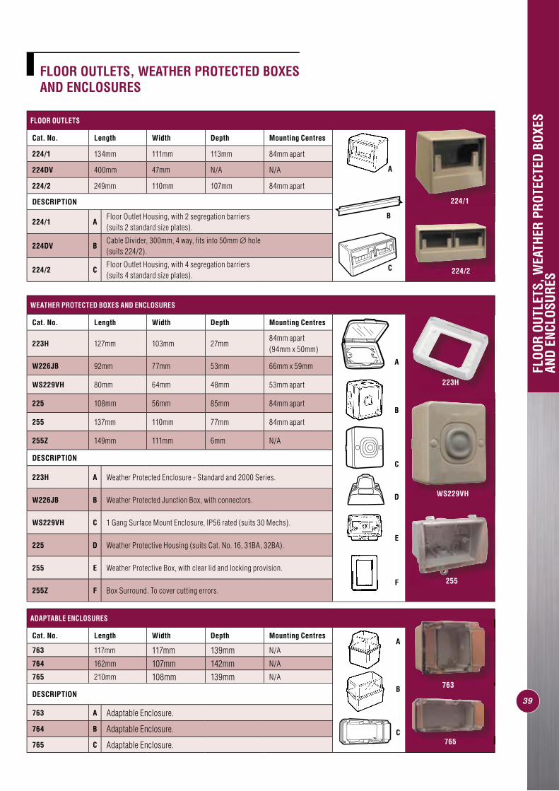
FLOOR OUTLETS, WEATHER PROTECTED BOXES AND ENCLOSURES
39
FLOOR OUTLETS
Cat. No. Length Width Depth Mounting Centres
224/1 134mm 111mm 113mm 84mm apart
224DV 400mm 47mm N/A N/A
224/2 249mm 110mm 107mm 84mm apart
DESCRIPTION
224/1 AFloor Outlet Housing, with 2 segregation barriers (suits 2 standard size plates).
224DV BCable Divider, 300mm, 4 way, fi ts into 50mm ∅ hole (suits 224/2).
224/2 CFloor Outlet Housing, with 4 segregation barriers (suits 4 standard size plates).
A
B
C
FLOO
R OU
TLET
S, W
EATH
ER P
ROTE
CTED
BOX
ES
AND
ENCL
OSUR
ES
WEATHER PROTECTED BOXES AND ENCLOSURES
Cat. No. Length Width Depth Mounting Centres
223H 127mm 103mm 27mm84mm apart(94mm x 50mm)
W226JB 92mm 77mm 53mm 66mm x 59mm
WS229VH 80mm 64mm 48mm 53mm apart
225 108mm 56mm 85mm 84mm apart
255 137mm 110mm 77mm 84mm apart
255Z 149mm 111mm 6mm N/A
DESCRIPTION
223H A Weather Protected Enclosure - Standard and 2000 Series.
W226JB B Weather Protected Junction Box, with connectors.
WS229VH C 1 Gang Surface Mount Enclosure, IP56 rated (suits 30 Mechs).
225 D Weather Protective Housing (suits Cat. No. 16, 31BA, 32BA).
255 E Weather Protective Box, with clear lid and locking provision.
255Z F Box Surround. To cover cutting errors.
B
D
E
F
C
A
ADAPTABLE ENCLOSURES
Cat. No. Length Width Depth Mounting Centres
763 117mm 117mm 139mm N/A
764 162mm 107mm 142mm N/A
765 210mm 108mm 139mm N/A
DESCRIPTION
763 A Adaptable Enclosure.
764 B Adaptable Enclosure.
765 C Adaptable Enclosure.
A
B
C
224/1
223H
255
WS229VH
765
224/2
763
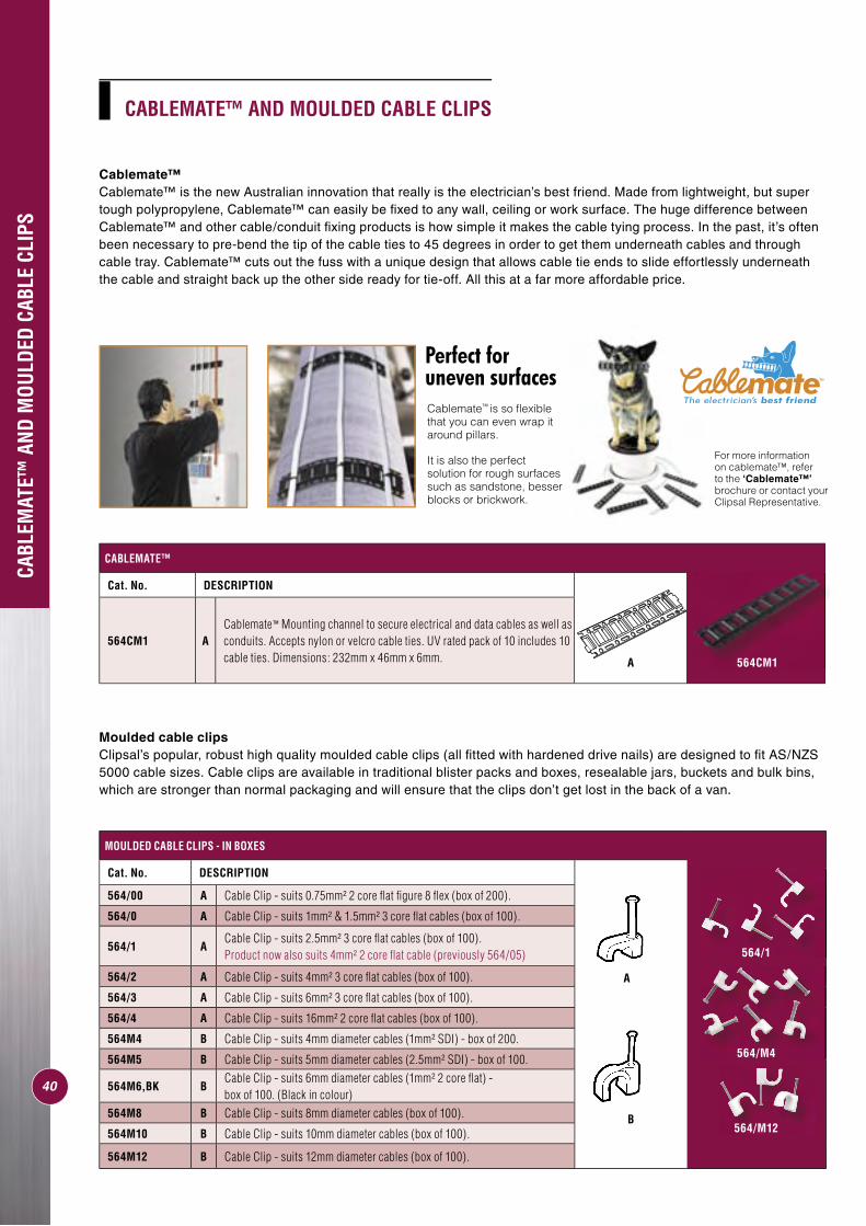
40
CABLEMATE™ AND MOULDED CABLE CLIPS
Cablemate™Cablemate™ is the new Australian innovation that really is the electrician’s best friend. Made from lightweight, but super tough polypropylene, Cablemate™ can easily be fi xed to any wall, ceiling or work surface. The huge difference between Cablemate™ and other cable/conduit fi xing products is how simple it makes the cable tying process. In the past, it’s often been necessary to pre-bend the tip of the cable ties to 45 degrees in order to get them underneath cables and through cable tray. Cablemate™ cuts out the fuss with a unique design that allows cable tie ends to slide effortlessly underneath the cable and straight back up the other side ready for tie-off. All this at a far more affordable price.
CABL
EMAT
E™ A
ND M
OULD
ED C
ABLE
CLI
PS
MOULDED CABLE CLIPS - IN BOXES
Cat. No. DESCRIPTION
A
B
564/00 A Cable Clip - suits 0.75mm² 2 core fl at fi gure 8 fl ex (box of 200).
564/0 A Cable Clip - suits 1mm² & 1.5mm² 3 core fl at cables (box of 100).
564/1 ACable Clip - suits 2.5mm² 3 core fl at cables (box of 100). Product now also suits 4mm² 2 core fl at cable (previously 564/05)
564/2 A Cable Clip - suits 4mm² 3 core fl at cables (box of 100).
564/3 A Cable Clip - suits 6mm² 3 core fl at cables (box of 100).
564/4 A Cable Clip - suits 16mm² 2 core fl at cables (box of 100).
564M4 B Cable Clip - suits 4mm diameter cables (1mm² SDI) - box of 200.
564M5 B Cable Clip - suits 5mm diameter cables (2.5mm² SDI) - box of 100.
564M6,BK BCable Clip - suits 6mm diameter cables (1mm² 2 core fl at) - box of 100. (Black in colour)
564M8 B Cable Clip - suits 8mm diameter cables (box of 100).
564M10 B Cable Clip - suits 10mm diameter cables (box of 100).
564M12 B Cable Clip - suits 12mm diameter cables (box of 100).
564/1
564/M4
564/M12
CABLEMATE™
Cat. No. DESCRIPTION
564CM1 ACablemate™ Mounting channel to secure electrical and data cables as well as conduits. Accepts nylon or velcro cable ties. UV rated pack of 10 includes 10 cable ties. Dimensions: 232mm x 46mm x 6mm. 564CM1A
For more information on cablemate™, refer to the ‘Cablemate™’ brochure or contact your Clipsal Representative.
Perfect foruneven surfacesCablemate™ is so fl exible that you can even wrap it around pillars.
It is also the perfect solution for rough surfaces such as sandstone, besser blocks or brickwork.
Moulded cable clipsClipsal’s popular, robust high quality moulded cable clips (all fi tted with hardened drive nails) are designed to fi t AS/NZS 5000 cable sizes. Cable clips are available in traditional blister packs and boxes, resealable jars, buckets and bulk bins, which are stronger than normal packaging and will ensure that the clips don’t get lost in the back of a van.
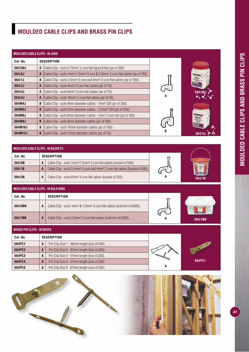
41
MOULDED CABLE CLIPS AND BRASS PIN CLIPS
MOULDED CABLE CLIPS - IN JARS
Cat. No. DESCRIPTION
564/00J A Cable Clip - suits 0.75mm² 2 core fl at fi gure 8 fl ex (jar of 300)
564/0J A Cable Clip - suits 1mm²/1.5mm² 3 core & 2.5mm² 2 core fl at cables (jar of 150).
564/1J A Cable Clip - suits 2.5mm² 3 core and 4mm² 2 core fl at cables (jar of 100).
564/2J A Cable Clip - suits 4mm² 3 core fl at cables (jar of 70).
564/3J A Cable Clip - suits 6mm² 3 core fl at cables (jar of 70).
564/4J A Cable Clip - suits 16mm² 2 core fl at cables (jar of 70).
564M4J B Cable Clip - suits 4mm diameter cables - 1mm² SDI (jar of 300)
564M5J B Cable Clip - suits 5mm diameter cables - 2.5mm² SDI (jar of 500)
564M6J B Cable Clip - suits 6mm diameter cables - 1mm² 2 core fl at (jar of 100)
564M8J B Cable Clip - suits 8mm diameter cables (jar of 150).
564M10J B Cable Clip - suits 10mm diameter cables (jar of 100).
564M12J B Cable Clip - suits 12mm diameter cables (jar of 70).
MOU
LDED
CAB
LE C
LIPS
AND
BRA
SS P
IN C
LIPS
MOULDED CABLE CLIPS - IN BULK BINS
Cat. No. DESCRIPTION
564/0BB A Cable Clip - suits 1mm² & 1.5mm² 3 core fl at cables (bulk bin of 6000).
564/1BB A Cable Clip - suits 2.5mm² 3 core fl at cables (bulk bin of 5000).
BRASS PIN CLIPS - IN BOXES
Cat. No. DESCRIPTION
564PC1 A Pin Clip Size 1 - 38mm length (box of 200).
564PC2 A Pin Clip Size 2 - 45mm length (box of 200).
564PC3 A Pin Clip Size 3 - 51mm length (box of 200).
564PC4 A Pin Clip Size 4 - 57mm length (box of 200).
564PC5 A Pin Clip Size 5 - 67mm length (box of 200).
MOULDED CABLE CLIPS - IN BUCKETS
Cat. No. DESCRIPTION
564/0B A Cable Clip - suits 1mm²/1.5mm² 3 core fl at cables (bucket of 500).
564/1B A Cable Clip - suits 2.5mm² 3 core and 4mm² 2 core fl at cables (bucket of 500).
564/3B A Cable Clip - suits 6mm² 3 core fl at cables (bucket of 250).
A
B
A
A
A
564/1BB
564PC1
564/1B
564/3J
564/00J
SCREWS
Clipsal’s popular range of screws includes Bugle Head, Pan Head, Wafer Head and Washer Head type screws.
These screws are available in a variety of different packaging including hang sell bags, jars and buckets, which are all clear so that the right screw for the job can be found quickly and easily.
The mounting feet of the Clipsal Mounting Block and other accessories have been designed to accommodate the 357 Bugle Head screws (note - if using a Power Driver, please adjust torque setting appropriately).
Pan Head screws with 6.85mm ø heads are ideal for directly fi xing accessories such as light switches and power points to wall plugs, timber architraves and skirting boards, without interfering with the number ‘9’ cap. Screws with the 8mm ø head provide extra support when fi xing heavier products such as our 56 Series, without interfering with the interior IP cap.
Wafer Head screws are ideal for mounting accessories into a ‘C’ section and purlins and have a 9mm ø head that neatly fi ts Clipsal 56 Series mounting enclosures.
Also ideal for use when mounting accessories into a ‘C’ section and purlins, the 11.7mm ø head of the Washer Head screws will not pull through the base of mounting accessories.
The 11.7mm ø Washer Head Twin Start Needle Point screws are perfect for mounting fl uoros and similar fi ttings, as they attach quickly and will not pull through the mounting holes when tight.
SCRE
WS
42
357
Bugle Head Twin Start
Needle Point
357P
Pan Head Twin Start
Needle Point
357WF
Wafer Head
Drill Bit Tip
357WH
Washer Head
Drill Bit Tip
357WHP
Washer Head
Twin Start
Needle Point
Affi xing bracket using 357WF40 screws
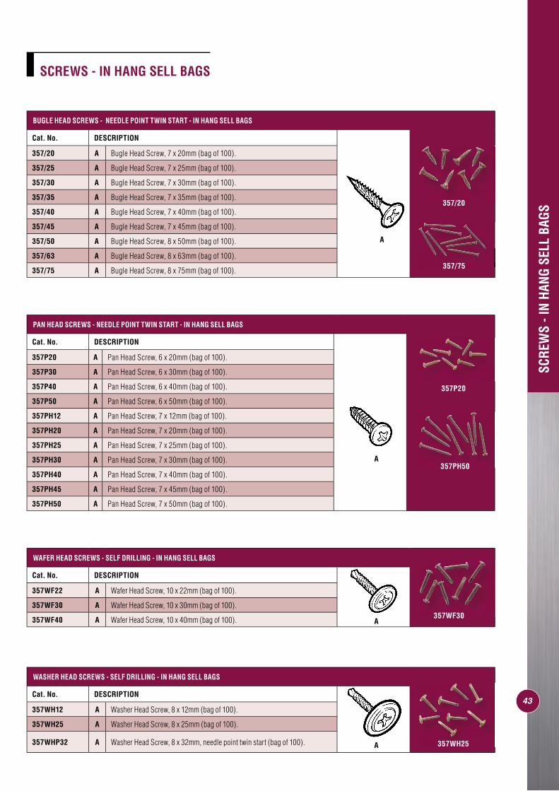
SCREWS - IN HANG SELL BAGS
PAN HEAD SCREWS - NEEDLE POINT TWIN START - IN HANG SELL BAGS
Cat. No. DESCRIPTION
357P20 A Pan Head Screw, 6 x 20mm (bag of 100).
357P30 A Pan Head Screw, 6 x 30mm (bag of 100).
357P40 A Pan Head Screw, 6 x 40mm (bag of 100).
357P50 A Pan Head Screw, 6 x 50mm (bag of 100).
357PH12 A Pan Head Screw, 7 x 12mm (bag of 100).
357PH20 A Pan Head Screw, 7 x 20mm (bag of 100).
357PH25 A Pan Head Screw, 7 x 25mm (bag of 100).
357PH30 A Pan Head Screw, 7 x 30mm (bag of 100).
357PH40 A Pan Head Screw, 7 x 40mm (bag of 100).
357PH45 A Pan Head Screw, 7 x 45mm (bag of 100).
357PH50 A Pan Head Screw, 7 x 50mm (bag of 100).
A
SCRE
WS
- IN
HANG
SEL
L BA
GS
WASHER HEAD SCREWS - SELF DRILLING - IN HANG SELL BAGS
Cat. No. DESCRIPTION
357WH12 A Washer Head Screw, 8 x 12mm (bag of 100).
357WH25 A Washer Head Screw, 8 x 25mm (bag of 100).
357WHP32 A Washer Head Screw, 8 x 32mm, needle point twin start (bag of 100). A
WAFER HEAD SCREWS - SELF DRILLING - IN HANG SELL BAGS
Cat. No. DESCRIPTION
357WF22 A Wafer Head Screw, 10 x 22mm (bag of 100).
357WF30 A Wafer Head Screw, 10 x 30mm (bag of 100).
357WF40 A Wafer Head Screw, 10 x 40mm (bag of 100). A
BUGLE HEAD SCREWS - NEEDLE POINT TWIN START - IN HANG SELL BAGS
Cat. No. DESCRIPTION
357/20 A Bugle Head Screw, 7 x 20mm (bag of 100).
357/25 A Bugle Head Screw, 7 x 25mm (bag of 100).
357/30 A Bugle Head Screw, 7 x 30mm (bag of 100).
357/35 A Bugle Head Screw, 7 x 35mm (bag of 100).
357/40 A Bugle Head Screw, 7 x 40mm (bag of 100).
357/45 A Bugle Head Screw, 7 x 45mm (bag of 100).
357/50 A Bugle Head Screw, 8 x 50mm (bag of 100).
357/63 A Bugle Head Screw, 8 x 63mm (bag of 100).
357/75 A Bugle Head Screw, 8 x 75mm (bag of 100).
A
43
357P20
357PH50
357WH25
357WF30
357/20
357/75
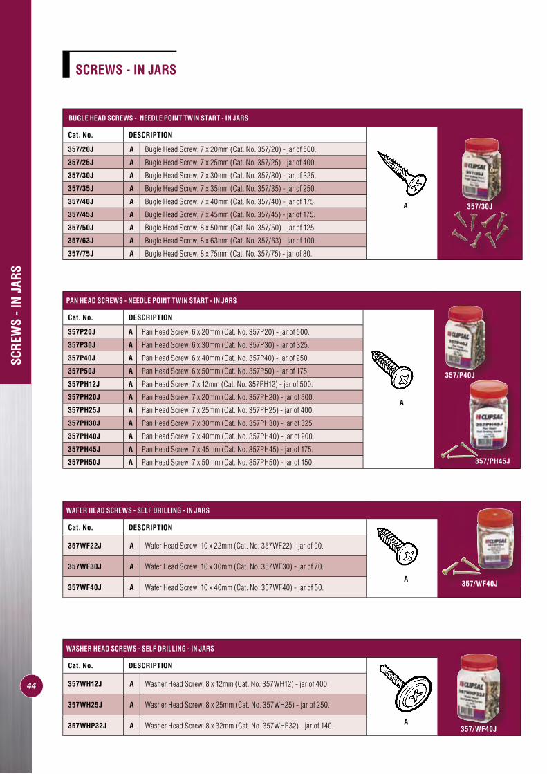
44
SCRE
WS
- IN
JARS
PAN HEAD SCREWS - NEEDLE POINT TWIN START - IN JARS
Cat. No. DESCRIPTION
A
357P20J A Pan Head Screw, 6 x 20mm (Cat. No. 357P20) - jar of 500.
357P30J A Pan Head Screw, 6 x 30mm (Cat. No. 357P30) - jar of 325.
357P40J A Pan Head Screw, 6 x 40mm (Cat. No. 357P40) - jar of 250.
357P50J A Pan Head Screw, 6 x 50mm (Cat. No. 357P50) - jar of 175.
357PH12J A Pan Head Screw, 7 x 12mm (Cat. No. 357PH12) - jar of 500.
357PH20J A Pan Head Screw, 7 x 20mm (Cat. No. 357PH20) - jar of 500.
357PH25J A Pan Head Screw, 7 x 25mm (Cat. No. 357PH25) - jar of 400.
357PH30J A Pan Head Screw, 7 x 30mm (Cat. No. 357PH30) - jar of 325.
357PH40J A Pan Head Screw, 7 x 40mm (Cat. No. 357PH40) - jar of 200.
357PH45J A Pan Head Screw, 7 x 45mm (Cat. No. 357PH45) - jar of 175.
357PH50J A Pan Head Screw, 7 x 50mm (Cat. No. 357PH50) - jar of 150.
WASHER HEAD SCREWS - SELF DRILLING - IN JARS
Cat. No. DESCRIPTION
357WH12J A Washer Head Screw, 8 x 12mm (Cat. No. 357WH12) - jar of 400.
357WH25J A Washer Head Screw, 8 x 25mm (Cat. No. 357WH25) - jar of 250.
357WHP32J A Washer Head Screw, 8 x 32mm (Cat. No. 357WHP32) - jar of 140.
BUGLE HEAD SCREWS - NEEDLE POINT TWIN START - IN JARS
Cat. No. DESCRIPTION
A
357/20J A Bugle Head Screw, 7 x 20mm (Cat. No. 357/20) - jar of 500.
357/25J A Bugle Head Screw, 7 x 25mm (Cat. No. 357/25) - jar of 400.
357/30J A Bugle Head Screw, 7 x 30mm (Cat. No. 357/30) - jar of 325.
357/35J A Bugle Head Screw, 7 x 35mm (Cat. No. 357/35) - jar of 250.
357/40J A Bugle Head Screw, 7 x 40mm (Cat. No. 357/40) - jar of 175.
357/45J A Bugle Head Screw, 7 x 45mm (Cat. No. 357/45) - jar of 175.
357/50J A Bugle Head Screw, 8 x 50mm (Cat. No. 357/50) - jar of 125.
357/63J A Bugle Head Screw, 8 x 63mm (Cat. No. 357/63) - jar of 100.
357/75J A Bugle Head Screw, 8 x 75mm (Cat. No. 357/75) - jar of 80.
SCREWS - IN JARS
WAFER HEAD SCREWS - SELF DRILLING - IN JARS
Cat. No. DESCRIPTION
357WF22J A Wafer Head Screw, 10 x 22mm (Cat. No. 357WF22) - jar of 90.
357WF30J A Wafer Head Screw, 10 x 30mm (Cat. No. 357WF30) - jar of 70.
357WF40J A Wafer Head Screw, 10 x 40mm (Cat. No. 357WF40) - jar of 50.
A
A
357/30J
357/PH45J
357/P40J
357/WF40J
357/WF40J
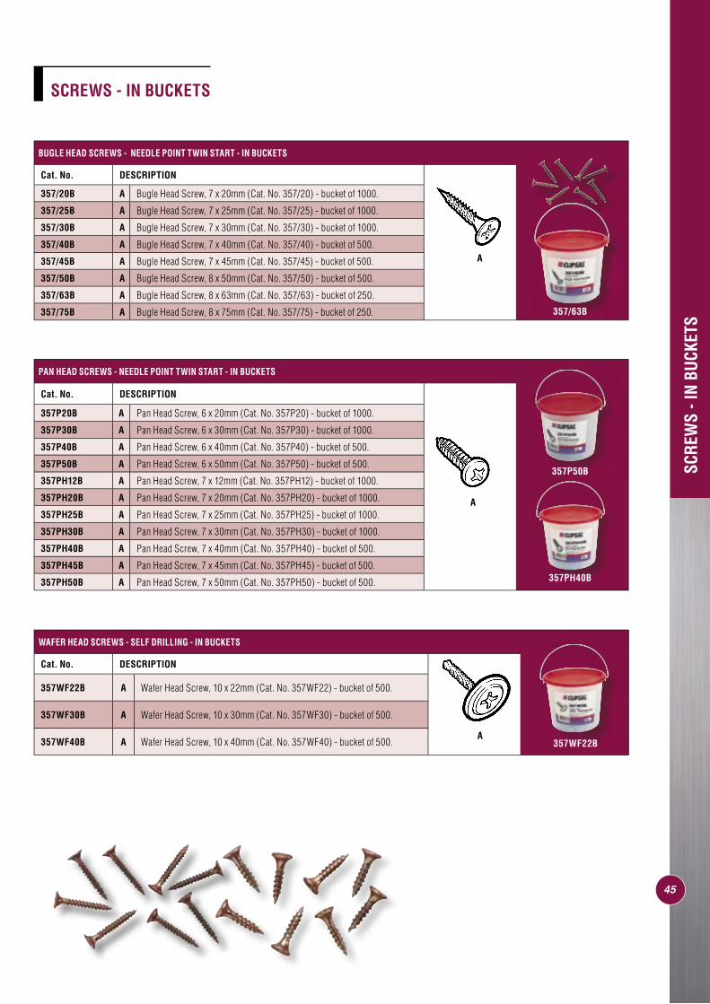
45
SCRE
WS
- IN
BUCK
ETS
BUGLE HEAD SCREWS - NEEDLE POINT TWIN START - IN BUCKETS
Cat. No. DESCRIPTION
A
357/20B A Bugle Head Screw, 7 x 20mm (Cat. No. 357/20) - bucket of 1000.
357/25B A Bugle Head Screw, 7 x 25mm (Cat. No. 357/25) - bucket of 1000.
357/30B A Bugle Head Screw, 7 x 30mm (Cat. No. 357/30) - bucket of 1000.
357/40B A Bugle Head Screw, 7 x 40mm (Cat. No. 357/40) - bucket of 500.
357/45B A Bugle Head Screw, 7 x 45mm (Cat. No. 357/45) - bucket of 500.
357/50B A Bugle Head Screw, 8 x 50mm (Cat. No. 357/50) - bucket of 500.
357/63B A Bugle Head Screw, 8 x 63mm (Cat. No. 357/63) - bucket of 250.
357/75B A Bugle Head Screw, 8 x 75mm (Cat. No. 357/75) - bucket of 250.
PAN HEAD SCREWS - NEEDLE POINT TWIN START - IN BUCKETS
Cat. No. DESCRIPTION
A
357P20B A Pan Head Screw, 6 x 20mm (Cat. No. 357P20) - bucket of 1000.
357P30B A Pan Head Screw, 6 x 30mm (Cat. No. 357P30) - bucket of 1000.
357P40B A Pan Head Screw, 6 x 40mm (Cat. No. 357P40) - bucket of 500.
357P50B A Pan Head Screw, 6 x 50mm (Cat. No. 357P50) - bucket of 500.
357PH12B A Pan Head Screw, 7 x 12mm (Cat. No. 357PH12) - bucket of 1000.
357PH20B A Pan Head Screw, 7 x 20mm (Cat. No. 357PH20) - bucket of 1000.
357PH25B A Pan Head Screw, 7 x 25mm (Cat. No. 357PH25) - bucket of 1000.
357PH30B A Pan Head Screw, 7 x 30mm (Cat. No. 357PH30) - bucket of 1000.
357PH40B A Pan Head Screw, 7 x 40mm (Cat. No. 357PH40) - bucket of 500.
357PH45B A Pan Head Screw, 7 x 45mm (Cat. No. 357PH45) - bucket of 500.
357PH50B A Pan Head Screw, 7 x 50mm (Cat. No. 357PH50) - bucket of 500.
WAFER HEAD SCREWS - SELF DRILLING - IN BUCKETS
Cat. No. DESCRIPTION
357WF22B A Wafer Head Screw, 10 x 22mm (Cat. No. 357WF22) - bucket of 500.
357WF30B A Wafer Head Screw, 10 x 30mm (Cat. No. 357WF30) - bucket of 500.
357WF40B A Wafer Head Screw, 10 x 40mm (Cat. No. 357WF40) - bucket of 500.A
SCREWS - IN BUCKETS
357/63B
357P50B
357PH40B
357WF22B
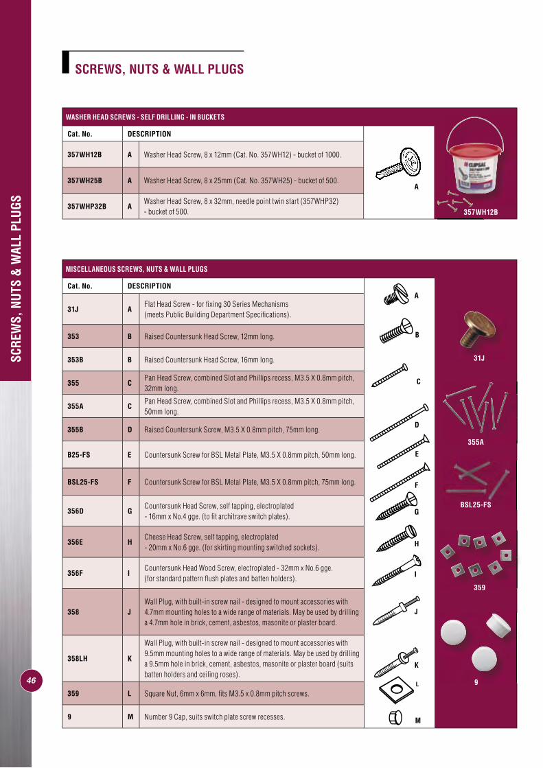
SCREWS, NUTS & WALL PLUGS
46
WASHER HEAD SCREWS - SELF DRILLING - IN BUCKETS
Cat. No. DESCRIPTION
357WH12B A Washer Head Screw, 8 x 12mm (Cat. No. 357WH12) - bucket of 1000.
357WH25B A Washer Head Screw, 8 x 25mm (Cat. No. 357WH25) - bucket of 500.
357WHP32B AWasher Head Screw, 8 x 32mm, needle point twin start (357WHP32) - bucket of 500.
A
SCRE
WS,
NUT
S &
WAL
L PL
UGS
MISCELLANEOUS SCREWS, NUTS & WALL PLUGS
Cat. No. DESCRIPTION
31J AFlat Head Screw - for fi xing 30 Series Mechanisms (meets Public Building Department Specifi cations).
353 B Raised Countersunk Head Screw, 12mm long.
353B B Raised Countersunk Head Screw, 16mm long.
355 CPan Head Screw, combined Slot and Phillips recess, M3.5 X 0.8mm pitch, 32mm long.
355A CPan Head Screw, combined Slot and Phillips recess, M3.5 X 0.8mm pitch, 50mm long.
355B D Raised Countersunk Screw, M3.5 X 0.8mm pitch, 75mm long.
B25-FS E Countersunk Screw for BSL Metal Plate, M3.5 X 0.8mm pitch, 50mm long.
BSL25-FS F Countersunk Screw for BSL Metal Plate, M3.5 X 0.8mm pitch, 75mm long.
356D GCountersunk Head Screw, self tapping, electroplated - 16mm x No.4 gge. (to fi t architrave switch plates).
356E HCheese Head Screw, self tapping, electroplated - 20mm x No.6 gge. (for skirting mounting switched sockets).
356F ICountersunk Head Wood Screw, electroplated - 32mm x No.6 gge. (for standard pattern fl ush plates and batten holders).
358 JWall Plug, with built-in screw nail - designed to mount accessories with 4.7mm mounting holes to a wide range of materials. May be used by drilling a 4.7mm hole in brick, cement, asbestos, masonite or plaster board.
358LH K
Wall Plug, with built-in screw nail - designed to mount accessories with 9.5mm mounting holes to a wide range of materials. May be used by drilling a 9.5mm hole in brick, cement, asbestos, masonite or plaster board (suits batten holders and ceiling roses).
359 L Square Nut, 6mm x 6mm, fi ts M3.5 x 0.8mm pitch screws.
9 M Number 9 Cap, suits switch plate screw recesses.
L
J
B
H
M
A
G
K
I
357WH12B
31J
355A
359
9
C
D
F
E
BSL25-FS
POWER DRIVE BITS
47
POWER DRIVE BITS
Cat. No. DESCRIPTION
357PB A Power Drive Bit, No. 2 Phillips Head, single ended - 100mm long.
357PB2 B Power Drive Bit, No. 2 Phillips Head, double ended - 100mm long.
357PB150 C Power Drive Bit, No. 2 Phillips Head, single ended - 150mm long.
357PBU D Power Drive Bit, No. 2 Phillips Head & 6mm fl at blade - 100mm long.
357NS E Power Drive Bit, 5/16” Nutsetter - 70mm long.
B
POW
ER D
RIVE
BIT
S
A
C
D
E
Installation using 357NS
357PB
357NS
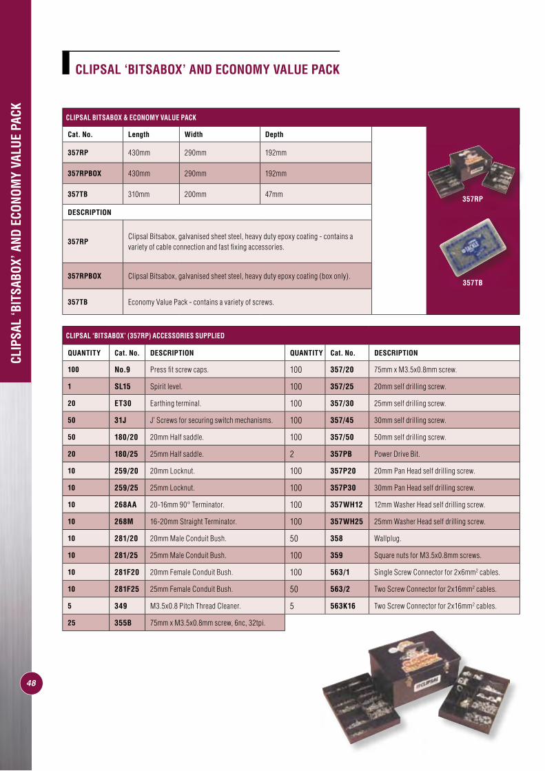
CLIPSAL BITSABOX & ECONOMY VALUE PACK
Cat. No. Length Width Depth
357RP 430mm 290mm 192mm
357RPBOX 430mm 290mm 192mm
357TB 310mm 200mm 47mm
DESCRIPTION
357RPClipsal Bitsabox, galvanised sheet steel, heavy duty epoxy coating - contains a variety of cable connection and fast fi xing accessories.
357RPBOX Clipsal Bitsabox, galvanised sheet steel, heavy duty epoxy coating (box only).
357TB Economy Value Pack - contains a variety of screws.
CLIP
SAL
‘BIT
SABO
X’ A
ND E
CONO
MY
VALU
E PA
CK
CLIPSAL ‘BITSABOX’ AND ECONOMY VALUE PACK
48
CLIPSAL ‘BITSABOX’ (357RP) ACCESSORIES SUPPLIED
QUANTITY Cat. No. DESCRIPTION QUANTITY Cat. No. DESCRIPTION
100 No.9 Press fi t screw caps. 100 357/20 75mm x M3.5x0.8mm screw.
1 SL15 Spirit level. 100 357/25 20mm self drilling screw.
20 ET30 Earthing terminal. 100 357/30 25mm self drilling screw.
50 31J J’ Screws for securing switch mechanisms. 100 357/45 30mm self drilling screw.
50 180/20 20mm Half saddle. 100 357/50 50mm self drilling screw.
20 180/25 25mm Half saddle. 2 357PB Power Drive Bit.
10 259/20 20mm Locknut. 100 357P20 20mm Pan Head self drilling screw.
10 259/25 25mm Locknut. 100 357P30 30mm Pan Head self drilling screw.
10 268AA 20-16mm 90° Terminator. 100 357WH12 12mm Washer Head self drilling screw.
10 268M 16-20mm Straight Terminator. 100 357WH25 25mm Washer Head self drilling screw.
10 281/20 20mm Male Conduit Bush. 50 358 Wallplug.
10 281/25 25mm Male Conduit Bush. 100 359 Square nuts for M3.5x0.8mm screws.
10 281F20 20mm Female Conduit Bush. 100 563/1 Single Screw Connector for 2x6mm2 cables.
10 281F25 25mm Female Conduit Bush. 50 563/2 Two Screw Connector for 2x16mm2 cables.
5 349 M3.5x0.8 Pitch Thread Cleaner. 5 563K16 Two Screw Connector for 2x16mm2 cables.
25 355B 75mm x M3.5x0.8mm screw, 6nc, 32tpi.
357RP
357TB
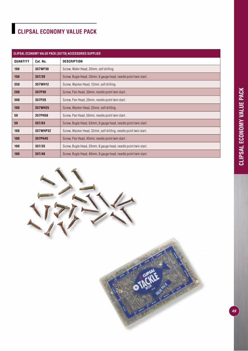
CLIPSAL ECONOMY VALUE PACK
CLIP
SAL
ECON
OMY
VALU
E PA
CK
49
CLIPSAL ECONOMY VALUE PACK (357TB) ACCESSORIES SUPPLIED
QUANTITY Cat. No. DESCRIPTION
100 357WF30 Screw, Wafer Head, 20mm, self drilling.
150 357/20 Screw, Bugle Head, 20mm, 8 gauge head, needle point twin start.
350 357WH12 Screw, Washer Head, 12mm, self drilling.
200 357P30 Screw, Pan Head, 30mm, needle point twin start.
300 357P20 Screw, Pan Head, 20mm, needle point twin start.
100 357WH25 Screw, Washer Head, 25mm, self drilling.
50 357PH50 Screw, Pan Head, 50mm, needle point twin start.
50 357/63 Screw, Bugle Head, 63mm, 8 gauge head, needle point twin start.
100 357WHP32 Screw, Washer Head, 32mm, self drilling, needle point twin start.
100 357PH45 Screw, Pan Head, 45mm, needle point twin start.
100 357/35 Screw, Bugle Head, 35mm, 8 gauge head, needle point twin start.
100 357/40 Screw, Bugle Head, 40mm, 8 gauge head, needle point twin start.
50
MOUNTING BLOCKS AND FLANGES
Cat. No. Description Length Width Depth Mounting CentresPage No.
2000SM Surround, deep, surface mounting. 118mm 78mm 27mm N/A 4
2000SMKSurface Mounting Kit, contains 2449ASD mounting fl ange & 2000SM deep surround.
118mm 78mm 27mm 84mm 4
2449ASDMounting Spacer (suitable for all 2000 Series assemblies).
114mm 68mm 14mm 84mm apart 4
2000MF300Mounting Flange, for 2000 Series (suits 300mm diameter surface - horizontal).
119mm 78mm 18mm 84mm apart 4
2000MF400Mounting Flange, for 2000 Series (suits 400mm diameter surface - horizontal).
119mm 78mm 18mm 84mm apart 4
2000MF500Mounting Flange, for 2000 Series (suits 500mm diameter surface - horizontal).
119mm 78mm 18mm 84mm apart 4
2000MF600Mounting Flange, for 2000 Series (suits 600mm diameter surface - horizontal).
119mm 78mm 18mm 84mm apart 4
2000MF800Mounting Flange, for 2000 Series (suits 800mm diameter surface - horizontal).
119mm 78mm 18mm 84mm apart 4
2000MFV300Mounting Flange, for 2000 Series (suits 300mm diameter surface - vertical).
119mm 78mm 18mm 84mm apart 4
2000MFV400Mounting Flange, for 2000 Series (suits 400mm diameter surface - vertical).
119mm 78mm 18mm 84mm apart 4
2000MFV500Mounting Flange, for 2000 Series (suits 500mm diameter surface - vertical).
119mm 78mm 18mm 84mm apart 4
2000MFV600Mounting Flange, for 2000 Series (suits 600mm diameter surface - vertical).
119mm 78mm 18mm 84mm apart 4
2000MFV800Mounting Flange, for 2000 Series (suits 800mm diameter surface - vertical).
119mm 78mm 18mm 84mm apart 4
C2015D4MBMounting Block, enables surface wiring with either conduit or mini duct.
198 mm 79mm 25mm 155mm x 50mm apart 8
MOULDED MOUNTING BLOCKS
471 Gang Surface Mounting Block, with metal inserts, impact resistant.
103mm 49mm 25mm 78mm apart 8
70B1 Gang Surface Mounting Block, with metal inserts, impact resistant.
99mm 52mm 25mm 55mm apart 8
70/11 Gang Surface Mounting Block, with metal inserts, impact resistant.
80mm 37mm 25mm 55mm apart 8
70/22 Gang Surface Mounting Block, with metal inserts, impact resistant.
90mm 37mm 25mm 70mm apart 8
70/33 Gang Surface Mounting Block, with metal inserts, impact resistant.
116mm 36mm 25mm 97mm apart 8
4471 Gang Surface Mounting Block, with metal inserts.(suits 40, 40D and switches with 115 x 48mm fl ush plates and 98mm mounting centres).
103mm 49mm 25mm 78mm apart 8
448 2 Gang Surface Mounting Block, with metal inserts. 120mm 120mm 28mm 84mm x 46mm 8
449A 1 Gang Surface Mounting Block, with metal inserts. 122mm 78mm 32mm 84mm x 46mm 8
MOUNTING ACCESSORIES QUICK REFERENCE GUIDE
MOU
NTIN
G AC
CESS
ORIE
S QU
ICK
REFE
RENC
E GU
IDE
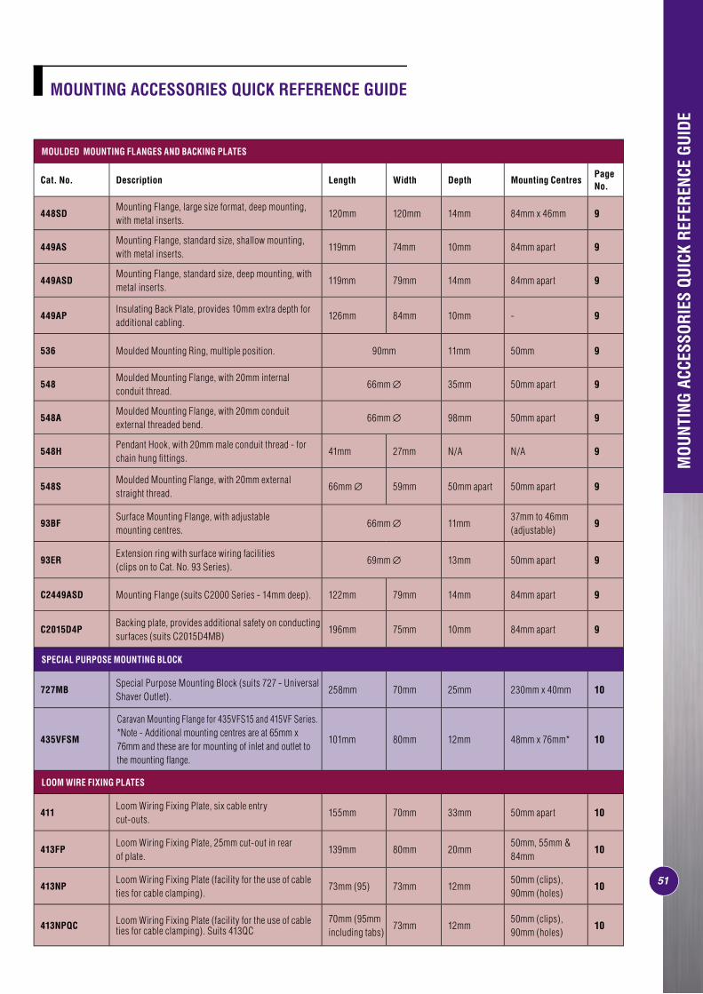
51
MOULDED MOUNTING FLANGES AND BACKING PLATES
Cat. No. Description Length Width Depth Mounting CentresPage No.
448SDMounting Flange, large size format, deep mounting, with metal inserts.
120mm 120mm 14mm 84mm x 46mm 9
449ASMounting Flange, standard size, shallow mounting, with metal inserts.
119mm 74mm 10mm 84mm apart 9
449ASDMounting Flange, standard size, deep mounting, with metal inserts.
119mm 79mm 14mm 84mm apart 9
449APInsulating Back Plate, provides 10mm extra depth for additional cabling.
126mm 84mm 10mm - 9
536 Moulded Mounting Ring, multiple position. 90mm 11mm 50mm 9
548Moulded Mounting Flange, with 20mm internal conduit thread.
66mm ∅ 35mm 50mm apart 9
548AMoulded Mounting Flange, with 20mm conduit external threaded bend.
66mm ∅ 98mm 50mm apart 9
548HPendant Hook, with 20mm male conduit thread - for chain hung fi ttings.
41mm 27mm N/A N/A 9
548SMoulded Mounting Flange, with 20mm external straight thread.
66mm ∅ 59mm 50mm apart 50mm apart 9
93BFSurface Mounting Flange, with adjustable mounting centres.
66mm ∅ 11mm37mm to 46mm (adjustable)
9
93ERExtension ring with surface wiring facilities (clips on to Cat. No. 93 Series).
69mm ∅ 13mm 50mm apart 9
C2449ASD Mounting Flange (suits C2000 Series - 14mm deep). 122mm 79mm 14mm 84mm apart 9
C2015D4PBacking plate, provides additional safety on conducting surfaces (suits C2015D4MB)
196mm 75mm 10mm 84mm apart 9
SPECIAL PURPOSE MOUNTING BLOCK
727MBSpecial Purpose Mounting Block (suits 727 - Universal Shaver Outlet).
258mm 70mm 25mm 230mm x 40mm 10
435VFSM
Caravan Mounting Flange for 435VFS15 and 415VF Series.*Note - Additional mounting centres are at 65mm x 76mm and these are for mounting of inlet and outlet to the mounting fl ange.
101mm 80mm 12mm 48mm x 76mm* 10
LOOM WIRE FIXING PLATES
411Loom Wiring Fixing Plate, six cable entry cut-outs.
155mm 70mm 33mm 50mm apart 10
413FPLoom Wiring Fixing Plate, 25mm cut-out in rear of plate.
139mm 80mm 20mm50mm, 55mm & 84mm
10
413NPLoom Wiring Fixing Plate (facility for the use of cable ties for cable clamping).
73mm (95) 73mm 12mm50mm (clips), 90mm (holes)
10
413NPQC Loom Wiring Fixing Plate (facility for the use of cable ties for cable clamping). Suits 413QC
70mm (95mm including tabs)
73mm 12mm50mm (clips), 90mm (holes)
10
MOU
NTIN
G AC
CESS
ORIE
S QU
ICK
REFE
RENC
E GU
IDE
MOUNTING ACCESSORIES QUICK REFERENCE GUIDE
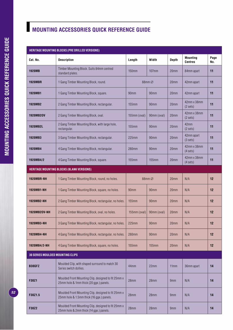
52
MOU
NTIN
G AC
CESS
ORIE
S QU
ICK
REFE
RENC
E GU
IDE
HERITAGE MOUNTING BLOCKS (PRE DRILLED VERSIONS)
Cat. No. Description Length Width DepthMounting Centres
Page No.
1920MBTimber Mounting Block. Suits 84mm centred standard plates.
150mm 107mm 20mm 84mm apart 11
1920MBR 1 Gang Timber Mounting Block, round. 88mm ∅ 20mm 42mm apart 11
1920MB1 1 Gang Timber Mounting Block, square. 90mm 90mm 20mm 42mm apart 11
1920MB2 2 Gang Timber Mounting Block, rectangular. 155mm 90mm 20mm42mm x 38mm (2 sets)
11
1920MB2OV 2 Gang Timber Mounting Block, oval. 155mm (oval) 90mm (oval) 20mm42mm x 38mm (2 sets)
11
1920MB2L2 Gang Timber Mounting Block, with large hole, rectangular.
155mm 90mm 20mm42mm (2 sets)
11
1920MB3 3 Gang Timber Mounting Block, rectangular. 225mm 90mm 20mm42mm apart (3 sets)
11
1920MB4 4 Gang Timber Mounting Block, rectangular. 280mm 90mm 20mm42mm x 38mm (4 sets)
11
1920MB4/2 4 Gang Timber Mounting Block, square. 155mm 155mm 20mm42mm x 38mm (4 sets)
11
HERITAGE MOUNTING BLOCKS (BLANK VERSIONS)
1920MBR-NH 1 Gang Timber Mounting Block, round, no holes. 88mm ∅ 20mm N/A 12
1920MB1-NH 1 Gang Timber Mounting Block, square, no holes. 90mm 90mm 20mm N/A 12
1920MB2-NH 2 Gang Timber Mounting Block, rectangular, no holes. 155mm 90mm 20mm N/A 12
1920MB2OV-NH 2 Gang Timber Mounting Block, oval, no holes. 155mm (oval) 90mm (oval) 20mm N/A 12
1920MB3-NH 3 Gang Timber Mounting Block, rectangular, no holes. 225mm 90mm 20mm N/A 12
1920MB4-NH 4 Gang Timber Mounting Block, rectangular, no holes. 280mm 90mm 20mm N/A 12
1920MB4/2-NH 4 Gang Timber Mounting Block, square, no holes. 155mm 155mm 20mm N/A 12
30 SERIES MOULDED MOUNTING CLIPS
B30GFZMoulded Clip, with shaped surround to match 30 Series switch dollies.
44mm 22mm 11mm 36mm apart 14
F30Z1Moulded Front Mounting Clip, designed to fi t 25mm x 25mm hole & 1mm thick (20 gge.) panels.
28mm 28mm 9mm N/A 14
F30Z1.5Moulded Front Mounting Clip, designed to fi t 25mm x 25mm hole & 1.5mm thick (16 gge.) panels.
28mm 28mm 9mm N/A 14
F30Z2Moulded Front Mounting Clip, designed to fi t 25mm x 25mm hole & 2mm thick (14 gge.) panels.
28mm 28mm 9mm N/A 14
MOUNTING ACCESSORIES QUICK REFERENCE GUIDE
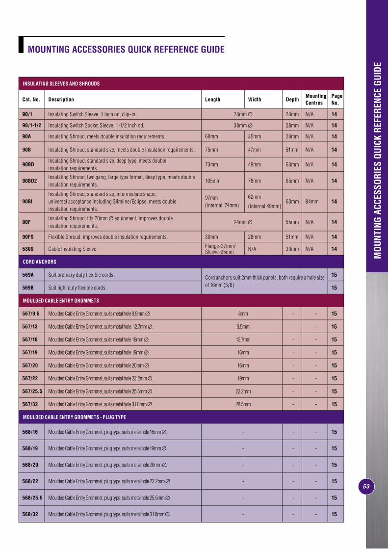
5353
INSULATING SLEEVES AND SHROUDS
Cat. No. Description Length Width DepthMounting Centres
Page No.
90/1 Insulating Switch Sleeve, 1 inch od, clip-in. 28mm ∅ 28mm N/A 14
90/1-1/2 Insulating Switch Socket Sleeve, 1-1/2 inch od. 38mm ∅ 28mm N/A 14
90A Insulating Shroud, meets double insulation requirements. 68mm 35mm 28mm N/A 14
90B Insulating Shroud, standard size, meets double insulation requirements. 75mm 47mm 51mm N/A 14
90BDInsulating Shroud, standard size, deep type, meets double insulation requirements.
73mm 49mm 63mm N/A 14
90BD2Insulating Shroud, two gang, large type format, deep type, meets double insulation requirements.
105mm 78mm 65mm N/A 14
90BIInsulating Shroud, standard size, intermediate shape, universal acceptance including Slimline/Eclipse, meets double insulation requirements.
97mm (internal 74mm)
62mm
(internal 49mm)63mm 84mm 14
90FInsulating Shroud, fi ts 20mm ∅ equipment, improves double insulation requirements.
24mm ∅ 55mm N/A 14
90FS Flexible Shroud, improves double insulation requirements. 30mm 28mm 51mm N/A 14
530S Cable Insulating Sleeve. Flange-37mm/Sleeve-25mm N/A 33mm N/A 14
CORD ANCHORS
569A Suit ordinary duty fl exible cords. Cord anchors suit 2mm thick panels, both require a hole size of 16mm (5/8)
15
569B Suit light duty fl exible cords. 15
MOULDED CABLE ENTRY GROMMETS
567/9.5 Moulded Cable Entry Grommet, suits metal hole 9.5mm ∅. 8mm - - 15
567/13 Moulded Cable Entry Grommet, suits metal hole 12.7mm ∅. 9.5mm - - 15
567/16 Moulded Cable Entry Grommet, suits metal hole 16mm ∅. 12.7mm - - 15
567/19 Moulded Cable Entry Grommet, suits metal hole 19mm ∅. 16mm - - 15
567/20 Moulded Cable Entry Grommet, suits metal hole 20mm ∅. 16mm - - 15
567/22 Moulded Cable Entry Grommet, suits metal hole 22.2mm ∅. 19mm - - 15
567/25.5 Moulded Cable Entry Grommet, suits metal hole 25.5mm ∅. 22.2mm - - 15
567/32 Moulded Cable Entry Grommet, suits metal hole 31.8mm ∅. 28.5mm - - 15
MOULDED CABLE ENTRY GROMMETS - PLUG TYPE
568/16 Moulded Cable Entry Grommet, plug type, suits metal hole 16mm ∅. - - - 15
568/19 Moulded Cable Entry Grommet, plug type, suits metal hole 19mm ∅. - - - 15
568/20 Moulded Cable Entry Grommet, plug type, suits metal hole 20mm ∅. - - - 15
568/22 Moulded Cable Entry Grommet, plug type, suits metal hole 22.2mm ∅. - - - 15
568/25.5 Moulded Cable Entry Grommet, plug type, suits metal hole 25.5mm ∅. - - - 15
568/32 Moulded Cable Entry Grommet, plug type, suits metal hole 31.8mm ∅. - - - 15
MOU
NTIN
G AC
CESS
ORIE
S QU
ICK
REFE
RENC
E GU
IDE
MOUNTING ACCESSORIES QUICK REFERENCE GUIDE
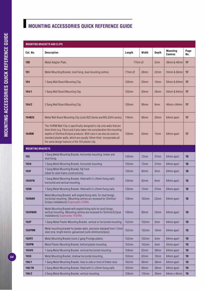
54
MOUNTING BRACKETS AND CLIPS
Cat. No. Description Length Width DepthMounting Centres
Page No.
150 Metal Adaptor Plate. 77mm ∅ 3mm 38mm & 46mm 17
151 Metal Mounting Bracket, stud fi xing, dual mounting centres. 77mm ∅ 28mm 22mm 55mm & 60mm 17
154 1 Gang Wall Board Mounting Clip. 120mm 50mm 13mm 50mm & 84mm 17
154/1 1 Gang Wall Board Mounting Clip. 120mm 50mm 26mm 50mm & 84mm 17
154/2 2 Gang Wall Board Mounting Clip. 120mm 96mm 9mm 46mm x 84mm 17
154B25 Metal Wall Board Mounting Clip (suits B25 Series and BSL25XA series). 110mm 96mm 20mm 84mm apart 17
154RM
The 154RM Wall Clip is specifi cally designed to clip onto walls that are 5mm thick (e.g. Fibro) and it also takes into consideration the mounting depths of Slimline/Eclipse products. With care it can also be used on standard plaster walls, which are usually 10mm thick. Incorporates all the same design features of the 154 plaster clip.
120mm 50mm 11mm 84mm apart 17
MOUNTING BRACKETS
1551 Gang Metal Mounting Bracket, horizontal mounting, timber and stud fi xing.
135mm 72mm 37mm 84mm apart 18
155A 1 Gang Metal Mounting Bracket, horizontal mounting. 135mm 72mm 37mm 84mm apart 18
155F1 Gang Metal Mounting Bracket, fl at front. (Ideal for steel frame constructions)
135mm 92mm 3mm 84mm apart 18
155VFN1 Gang Metal Mounting Bracket, fi tted with 2 x 25mm fi xing nails, horizontal and vertical mounting.
135mm 92mm 6mm 84mm apart 18
155N 1 Gang Metal Mounting Bracket, fi tted with 2 x 25mm fi xing nails. 135mm 72mm 37mm 84mm apart 18
155NARMetal Mounting Bracket, with angled fi xing nails, for stud fi xings, horizontal mounting. (Mounting centres are recessed for Slimline/Eclipse installations) Supersedes 155NA.
128mm 102mm 22mm 84mm apart 18
155VNARMetal Mounting Bracket with angled fi xing nails for stud fi xings, vertical mounting. (Mounting centres are recessed for Slimline/Eclipse installations) Supersedes 155VNA.
130mm 90mm 22mm 84mm apart 18
155P 1 Gang Metal Plaster Mounting Bracket, vertical or horizontal mounting. 152mm 152mm 3mm 84mm apart 19
155PRM Metal mounting bracket for plaster walls, precision stamped from 1.2mm steel strip bright electro-galvanised (suits slimline/eclipse) 152mm 152mm 10mm 84mm apart 19
155P2 Metal Mounting Bracket (suits 2 gang Prestige plates). 152mm 152mm 3mm 84mm apart 19
155PM Metal Plaster Mounting Bracket, behind plaster mounting. 152mm 152mm 3mm 55mm apart 19
155VH 1 Gang Metal Mounting Bracket, vertical/horizontal mounting. 158mm 92mm 38mm 84mm apart 19
155S Metal Mounting Bracket, shallow horizontal mounting. 163mm 63mm 10mm 84mm apart 19
156/1 1 Gang Metal Mounting Bracket, fi xes to side or front of timber stud. 102mm 90mm 38mm 84mm apart 19
156/1N 2 Gang Metal Mounting Bracket, fi tted with 2 x 25mm fi xing nails. 102mm 90mm 38mm 84mm apart 19
156/2 2 Gang Metal Mounting Bracket, vertical mounting. 129mm 115mm 39mm 84mm x 46mm 19
MOUNTING ACCESSORIES QUICK REFERENCE GUIDE
MOU
NTIN
G AC
CESS
ORIE
S QU
ICK
REFE
RENC
E GU
IDE

55
MOUNTING CLIPS AND MOUNTING BRACKETS
Cat. No. Description Length Width DepthMounting Centres
Page No.
2154/2 2 Gang Metal Wall Board Mounting Clip. 158mm 157mm 17mm 84mm x 72mm 20
2154H2 2 Gang Metal Wall Board Mounting Clip (suits 2000H2 series). 232mm 84mm 19mm 84mm apart (2 sets) 20
2154H3 3 Gang Metal Wall Board Mounting Clip (suits 2000H3 series). 348mm 84mm 8mm 84mm apart (3 sets) 20
2154/3 3 Gang Metal Wall Board Mounting Clip (suits 2000 series). 229mm 113mm 3mm 84mm x 73mm (2 sets) 20
2154/4 4 Gang Metal Wall Board Mounting Clip (suits 2000 series). 278mm 100mm 57mm84mm x 72mm (2 sets)
20
2155PRM22 Gang Metal Plaster Mounted Bracket (suits 2000/2 Series). Suitable for Slimline/Eclipse. Supersedes 2155P2.
170mm 220mm 13mm84mm x 70mm(2 sets)
20
2155PHRM22 Gang Metal Plaster Mounted Bracket (suits 2000/2 Series). Suitable for Slimline/Eclipse. Supersedes 2155PH2.
300mm 180mm 13mm84mm apart (2 sets)
20
2155PRM3 3 Gang Metal Plaster Mounted Bracket (suits 2000/2 Series). Supersedes 2155P3. 240mm 220mm 13mm 84mm x 73mm
(2 sets) 20
2155PHRM34 Gang Metal Plaster Mounted Bracket, horizontal mounting. Suitable for Slimline/Eclipse. Supersedes 2155PH3.
420mm 180mm 13mm 84mm apart (3 sets) 20
2155PRM4 4 Gang Metal Plaster Mounted Bracket. Suitable for 2000/4 and 2025V3/30PF products. Supersedes 2155P4. 310mm 220mm 13mm 84mm apart
(4 sets) 20
PLASTIC WALL BOXES
157/1P
1 Gang Moulded Plastic Wall Box, with sliding nuts and ample cut-outs, impact resistant (suits universal wall construction). Suitable for Standard, 2000, C2000, Metal Plate. Not suitable for Slimline & Eclipse unless recessed back 8mm.
97mm 60mm 45mm 84mm apart 23
157/1PRM
1 Gang Moulded Plastic Wall Box, with sliding nuts and ample cut-outs, impact resistant (suits universal wall construction) Suitable for all 84mm centred products, including Slimline and Eclipse. May require longer mounting screws (355A) on some installations
98mm 61mm 45mm 84mm apart 23
257 1 Gang Moulded Plastic Wall Box, with cut-outs, impact resistant. 94mm 58mm 44mm 84mm apart 23
257A 1 Gang Wall Box, with one 16-20mm end entry and one 16-20mm side entry, impact resistant. 94mm 58mm 44mm 84mm apart 23
257CC 1 Gang Moulded Wall Box, with two 20mm entry spouts one end. 98mm 58mm 44mm 84mm apart 23
257D 1 Gang Moulded Plastic Wall Box, with cut-outs, deep type. 94mm 58mm 61mm 84mm apart 23
257DBB 1 Gang Moulded Wall Box, with two 20mm entry spouts one side, deep type. 94mm 58mm 61mm 84mm apart 23
257DCC 1 Gang Moulded Wall Box, with two 20mm entry spouts one end, impact resistant, deep type. 94mm 58mm 61mm 84mm apart 23
257D2 2 Gang Moulded Plastic Wall Box, with 20mm cut-outs one end and 25mm cut-outs at other, impact resistant, deep type. 102mm 96mm 60mm 84mm x 46mm 23
257D3 3 Gang Moulded Plastic Wall Box, impact resistant, deep type. 148mm 96mm 60mm 84mm x 46mm 23
MOUNTING ACCESSORIES QUICK REFERENCE GUIDE
MOU
NTIN
G AC
CESS
ORIE
S QU
ICK
REFE
RENC
E GU
IDE
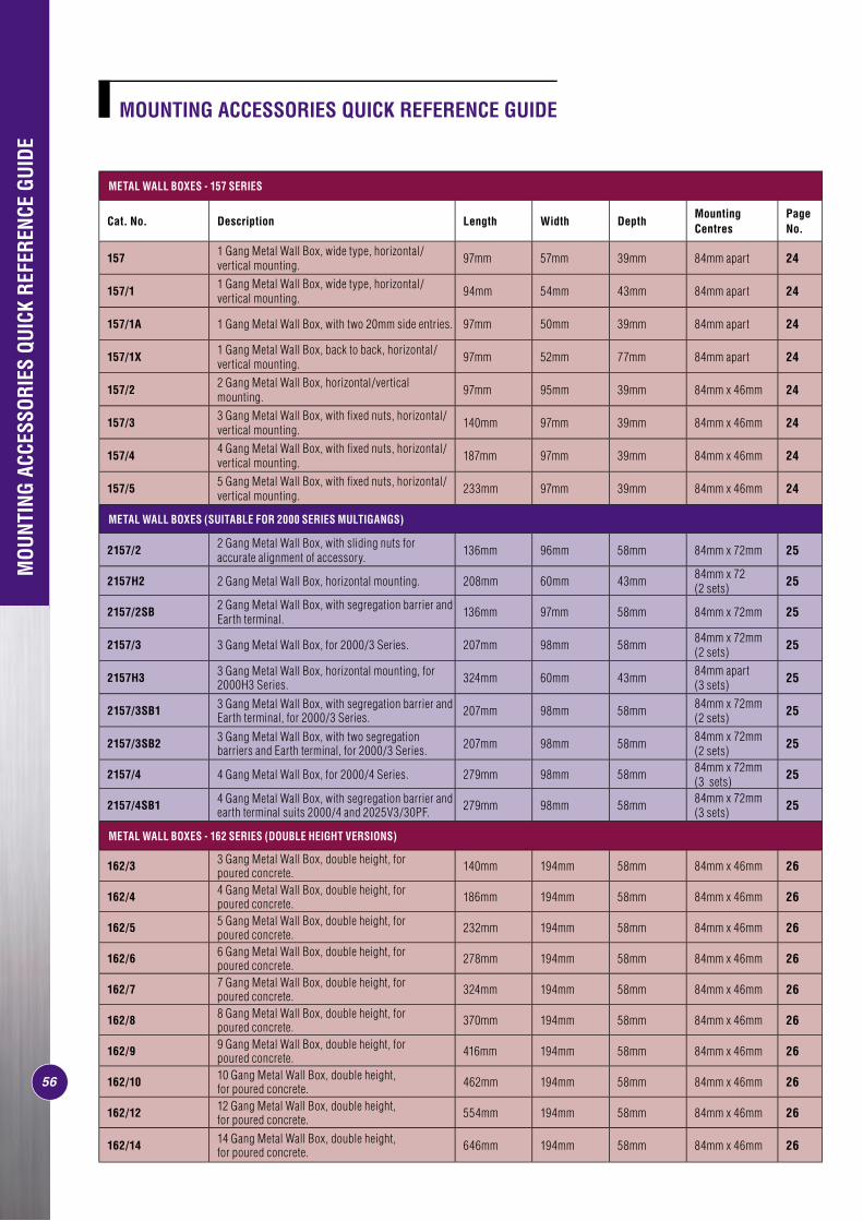
56
METAL WALL BOXES - 157 SERIES
Cat. No. Description Length Width DepthMounting Centres
Page No.
157 1 Gang Metal Wall Box, wide type, horizontal/vertical mounting. 97mm 57mm 39mm 84mm apart 24
157/1 1 Gang Metal Wall Box, wide type, horizontal/vertical mounting. 94mm 54mm 43mm 84mm apart 24
157/1A 1 Gang Metal Wall Box, with two 20mm side entries. 97mm 50mm 39mm 84mm apart 24
157/1X 1 Gang Metal Wall Box, back to back, horizontal/vertical mounting. 97mm 52mm 77mm 84mm apart 24
157/2 2 Gang Metal Wall Box, horizontal/vertical mounting. 97mm 95mm 39mm 84mm x 46mm 24
157/3 3 Gang Metal Wall Box, with fi xed nuts, horizontal/vertical mounting. 140mm 97mm 39mm 84mm x 46mm 24
157/4 4 Gang Metal Wall Box, with fi xed nuts, horizontal/vertical mounting. 187mm 97mm 39mm 84mm x 46mm 24
157/5 5 Gang Metal Wall Box, with fi xed nuts, horizontal/vertical mounting. 233mm 97mm 39mm 84mm x 46mm 24
METAL WALL BOXES (SUITABLE FOR 2000 SERIES MULTIGANGS)
2157/2 2 Gang Metal Wall Box, with sliding nuts for accurate alignment of accessory. 136mm 96mm 58mm 84mm x 72mm 25
2157H2 2 Gang Metal Wall Box, horizontal mounting. 208mm 60mm 43mm 84mm x 72(2 sets) 25
2157/2SB 2 Gang Metal Wall Box, with segregation barrier and Earth terminal. 136mm 97mm 58mm 84mm x 72mm 25
2157/3 3 Gang Metal Wall Box, for 2000/3 Series. 207mm 98mm 58mm 84mm x 72mm (2 sets) 25
2157H3 3 Gang Metal Wall Box, horizontal mounting, for 2000H3 Series. 324mm 60mm 43mm 84mm apart
(3 sets) 25
2157/3SB1 3 Gang Metal Wall Box, with segregation barrier and Earth terminal, for 2000/3 Series. 207mm 98mm 58mm 84mm x 72mm
(2 sets) 25
2157/3SB2 3 Gang Metal Wall Box, with two segregation barriers and Earth terminal, for 2000/3 Series. 207mm 98mm 58mm 84mm x 72mm
(2 sets) 25
2157/4 4 Gang Metal Wall Box, for 2000/4 Series. 279mm 98mm 58mm 84mm x 72mm (3 sets) 25
2157/4SB1 4 Gang Metal Wall Box, with segregation barrier and earth terminal suits 2000/4 and 2025V3/30PF. 279mm 98mm 58mm 84mm x 72mm
(3 sets) 25
METAL WALL BOXES - 162 SERIES (DOUBLE HEIGHT VERSIONS)
162/3 3 Gang Metal Wall Box, double height, for poured concrete. 140mm 194mm 58mm 84mm x 46mm 26
162/4 4 Gang Metal Wall Box, double height, for poured concrete. 186mm 194mm 58mm 84mm x 46mm 26
162/5 5 Gang Metal Wall Box, double height, for poured concrete. 232mm 194mm 58mm 84mm x 46mm 26
162/6 6 Gang Metal Wall Box, double height, for poured concrete. 278mm 194mm 58mm 84mm x 46mm 26
162/7 7 Gang Metal Wall Box, double height, for poured concrete. 324mm 194mm 58mm 84mm x 46mm 26
162/8 8 Gang Metal Wall Box, double height, for poured concrete. 370mm 194mm 58mm 84mm x 46mm 26
162/9 9 Gang Metal Wall Box, double height, for poured concrete. 416mm 194mm 58mm 84mm x 46mm 26
162/10 10 Gang Metal Wall Box, double height, for poured concrete. 462mm 194mm 58mm 84mm x 46mm 26
162/12 12 Gang Metal Wall Box, double height, for poured concrete. 554mm 194mm 58mm 84mm x 46mm 26
162/14 14 Gang Metal Wall Box, double height, for poured concrete. 646mm 194mm 58mm 84mm x 46mm 26
MOUNTING ACCESSORIES QUICK REFERENCE GUIDE
MOU
NTIN
G AC
CESS
ORIE
S QU
ICK
REFE
RENC
E GU
IDE

57
METAL WALL BOXES - 163,160 AND 164 SERIES (TRIPLE AND SINGLE HEIGHT VERSIONS)
Cat. No. Description Length Width Depth Mounting CentresPage No.
163/4 4 Gang Metal Wall Box, triple height, with fi xed nuts, for poured concrete. 289mm 186mm 58mm 84mm x 46mm 27
163/5 5 Gang Metal Wall Box, triple height, with fi xed nuts, for poured concrete. 289mm 232mm 58mm 84mm x 46mm 27
163/6 6 Gang Metal Wall Box, triple height, with fi xed nuts, for poured concrete. 289mm 278mm 290mm 84mm x 46mm 27
163/7 7 Gang Metal Wall Box, triple height, with fi xed nuts, for poured concrete. 289mm 324mm 290mm 84mm x 46mm 27
163/8 8 Gang Metal Wall Box, triple height, with fi xed nuts, for poured concrete. 289mm 370mm 58mm 84mm x 46mm 27
163/9 9 Gang Metal Wall Box, single height, for poured concrete. 416mm 289mm 58mm 84mm x 46mm 27
163/10 10 Gang Metal Wall Box, triple height, with fi xed nuts, for poured concrete. 289mm 462mm 58mm 84mm x 46mm apart 27
160 1 Gang Metal Wall Box, for poured concrete. 97mm 50mm 39mm 84mm apart 27
164 1 Gang Metal Wall Box, deep wide type, for poured concrete. 97mm 56mm 58mm 84mm apart 27
164/1 1 Gang Metal Wall Box, deep wide type, for poured concrete. 97mm 50mm 58mm 84mm apart 27
164/2 2 Gang Metal Wall Box, single height, for poured concrete. 97mm 96mm 58mm 84mm x 46mm apart 27
164/3 3 Gang Metal Wall Box, single height, for poured concrete. 97mm 142mm 58mm 84mm x 46mm apart 27
METAL WALL BOXES - 164 SERIES (SINGLE HEIGHT VERSION)
164/4 4 Gang Metal Wall Box, single height, for poured concrete. 97mm 188mm 58mm 84mm x 46mm apart 28
164/5 5 Gang Metal Wall Box, single height, for poured concrete. 97mm 234mm 58mm 84mm x 46mm apart 28
164/6 6 Gang Metal Wall Box, single height, for poured concrete. 97mm 280mm 58mm 84mm x 46mm apart 28
164/7 7 Gang Metal Wall Box, single height, for poured concrete. 97mm 326mm 58mm 84mm x 46mm apart 28
164/8 8 Gang Metal Wall Box, single height, for poured concrete. 97mm 372mm 58mm 84mm x 46mm apart 28
164/9 9 Gang Metal Wall Box, single height, for poured concrete. 97mm 418mm 58mm 84mm x 46mm apart 28
164/10 10 Gang Metal Wall Box, single height, for poured concrete. 97mm 464mm 58mm 84mm x 46mm apart 28
164/11 11 Gang Metal Wall Box, single height, for poured concrete. 97mm 510mm 58mm 84mm x 46mm apart 28
164/13 13 Gang Metal Wall Box, single height, for poured concrete. 97mm 602mm 58mm 84mm x 46mm apart 28
METAL WALL BOXES (ARCHITRAVES, SKIRTING AND SHAVER OUTLETS)
1581 Gang Miniature Metal Wall Box, with insulated sides, for 1 gang architrave plates and 1-2 gang B style moulded plates.
67mm 28mm 32mm 55mm apart 29
166 1 Gang Metal Wall Box, for skirting combinations. 97mm 39mm 39mm 78mm apart 29
727B Special Purpose Wall Box (for accommodation of Cat. No. 727 Universal Shaver Outlet). 240mm 58mm 58mm 230mm x 40mm 29
727VHB Special Purpose Wall Box, vertical/horizontal (for Cat. Nos, 727V and 727H Universal Shaver Outlets). 166mm 75mm 48mm 152mm 29
MOU
NTIN
G AC
CESS
ORIE
S QU
ICK
REFE
RENC
E GU
IDE
MOUNTING ACCESSORIES QUICK REFERENCE GUIDE
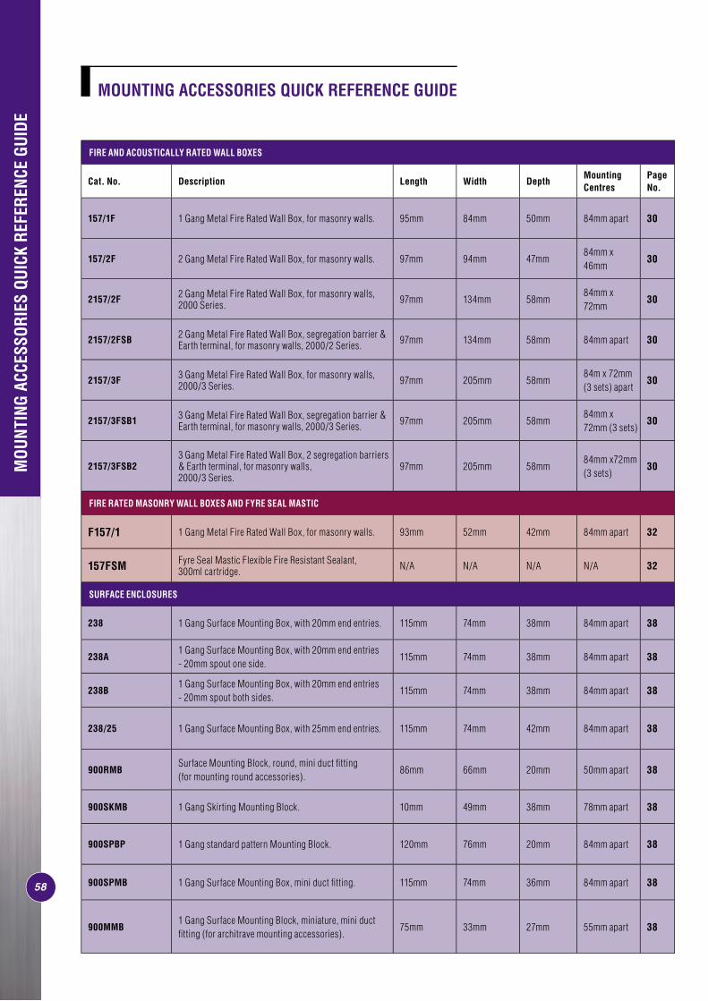
58
FIRE AND ACOUSTICALLY RATED WALL BOXES
Cat. No. Description Length Width DepthMounting Centres
Page No.
157/1F 1 Gang Metal Fire Rated Wall Box, for masonry walls. 95mm 84mm 50mm 84mm apart 30
157/2F 2 Gang Metal Fire Rated Wall Box, for masonry walls. 97mm 94mm 47mm84mm x 46mm
30
2157/2F 2 Gang Metal Fire Rated Wall Box, for masonry walls, 2000 Series. 97mm 134mm 58mm
84mm x 72mm
30
2157/2FSB 2 Gang Metal Fire Rated Wall Box, segregation barrier & Earth terminal, for masonry walls, 2000/2 Series. 97mm 134mm 58mm 84mm apart 30
2157/3F 3 Gang Metal Fire Rated Wall Box, for masonry walls, 2000/3 Series. 97mm 205mm 58mm
84m x 72mm (3 sets) apart
30
2157/3FSB1 3 Gang Metal Fire Rated Wall Box, segregation barrier & Earth terminal, for masonry walls, 2000/3 Series. 97mm 205mm 58mm
84mm x 72mm (3 sets)
30
2157/3FSB23 Gang Metal Fire Rated Wall Box, 2 segregation barriers & Earth terminal, for masonry walls, 2000/3 Series.
97mm 205mm 58mm84mm x72mm (3 sets)
30
FIRE RATED MASONRY WALL BOXES AND FYRE SEAL MASTIC
F157/1 1 Gang Metal Fire Rated Wall Box, for masonry walls. 93mm 52mm 42mm 84mm apart 32
157FSM Fyre Seal Mastic Flexible Fire Resistant Sealant, 300ml cartridge. N/A N/A N/A N/A 32
SURFACE ENCLOSURES
238 1 Gang Surface Mounting Box, with 20mm end entries. 115mm 74mm 38mm 84mm apart 38
238A1 Gang Surface Mounting Box, with 20mm end entries - 20mm spout one side.
115mm 74mm 38mm 84mm apart 38
238B1 Gang Surface Mounting Box, with 20mm end entries - 20mm spout both sides.
115mm 74mm 38mm 84mm apart 38
238/25 1 Gang Surface Mounting Box, with 25mm end entries. 115mm 74mm 42mm 84mm apart 38
900RMBSurface Mounting Block, round, mini duct fi tting (for mounting round accessories).
86mm 66mm 20mm 50mm apart 38
900SKMB 1 Gang Skirting Mounting Block. 10mm 49mm 38mm 78mm apart 38
900SPBP 1 Gang standard pattern Mounting Block. 120mm 76mm 20mm 84mm apart 38
900SPMB 1 Gang Surface Mounting Box, mini duct fi tting. 115mm 74mm 36mm 84mm apart 38
900MMB1 Gang Surface Mounting Block, miniature, mini duct fi tting (for architrave mounting accessories).
75mm 33mm 27mm 55mm apart 38
MOU
NTIN
G AC
CESS
ORIE
S QU
ICK
REFE
RENC
E GU
IDE
MOUNTING ACCESSORIES QUICK REFERENCE GUIDE
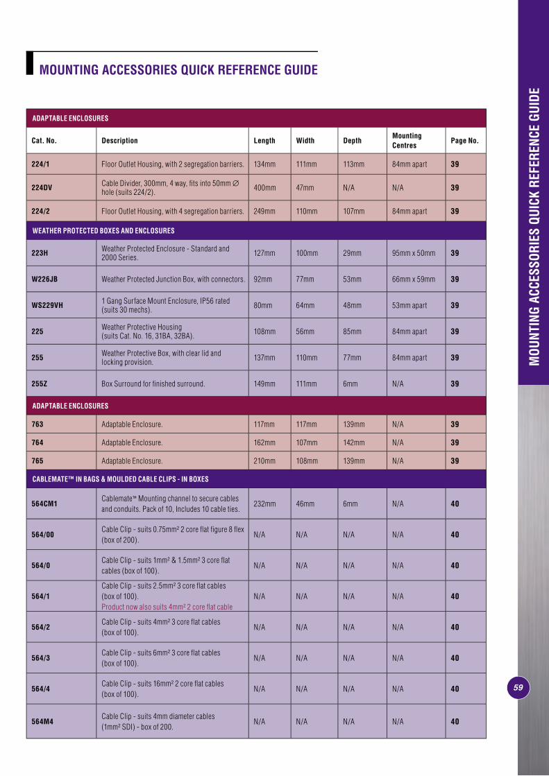
59
ADAPTABLE ENCLOSURES
Cat. No. Description Length Width DepthMounting Centres
Page No.
224/1 Floor Outlet Housing, with 2 segregation barriers. 134mm 111mm 113mm 84mm apart 39
224DV Cable Divider, 300mm, 4 way, fi ts into 50mm ∅ hole (suits 224/2). 400mm 47mm N/A N/A 39
224/2 Floor Outlet Housing, with 4 segregation barriers. 249mm 110mm 107mm 84mm apart 39
WEATHER PROTECTED BOXES AND ENCLOSURES
223H Weather Protected Enclosure - Standard and 2000 Series. 127mm 100mm 29mm 95mm x 50mm 39
W226JB Weather Protected Junction Box, with connectors. 92mm 77mm 53mm 66mm x 59mm 39
WS229VH 1 Gang Surface Mount Enclosure, IP56 rated (suits 30 mechs). 80mm 64mm 48mm 53mm apart 39
225 Weather Protective Housing (suits Cat. No. 16, 31BA, 32BA). 108mm 56mm 85mm 84mm apart 39
255 Weather Protective Box, with clear lid and locking provision. 137mm 110mm 77mm 84mm apart 39
255Z Box Surround for fi nished surround. 149mm 111mm 6mm N/A 39
ADAPTABLE ENCLOSURES
763 Adaptable Enclosure. 117mm 117mm 139mm N/A 39
764 Adaptable Enclosure. 162mm 107mm 142mm N/A 39
765 Adaptable Enclosure. 210mm 108mm 139mm N/A 39
CABLEMATE™ IN BAGS & MOULDED CABLE CLIPS - IN BOXES
564CM1Cablemate™ Mounting channel to secure cables and conduits. Pack of 10, Includes 10 cable ties.
232mm 46mm 6mm N/A 40
564/00Cable Clip - suits 0.75mm² 2 core fl at fi gure 8 fl ex (box of 200).
N/A N/A N/A N/A 40
564/0Cable Clip - suits 1mm² & 1.5mm² 3 core fl at cables (box of 100).
N/A N/A N/A N/A 40
564/1Cable Clip - suits 2.5mm² 3 core fl at cables (box of 100). Product now also suits 4mm² 2 core fl at cable
N/A N/A N/A N/A 40
564/2Cable Clip - suits 4mm² 3 core fl at cables (box of 100).
N/A N/A N/A N/A 40
564/3Cable Clip - suits 6mm² 3 core fl at cables (box of 100).
N/A N/A N/A N/A 40
564/4Cable Clip - suits 16mm² 2 core fl at cables (box of 100).
N/A N/A N/A N/A 40
564M4Cable Clip - suits 4mm diameter cables (1mm² SDI) - box of 200.
N/A N/A N/A N/A 40
MOUNTING ACCESSORIES QUICK REFERENCE GUIDE
MOU
NTIN
G AC
CESS
ORIE
S QU
ICK
REFE
RENC
E GU
IDE
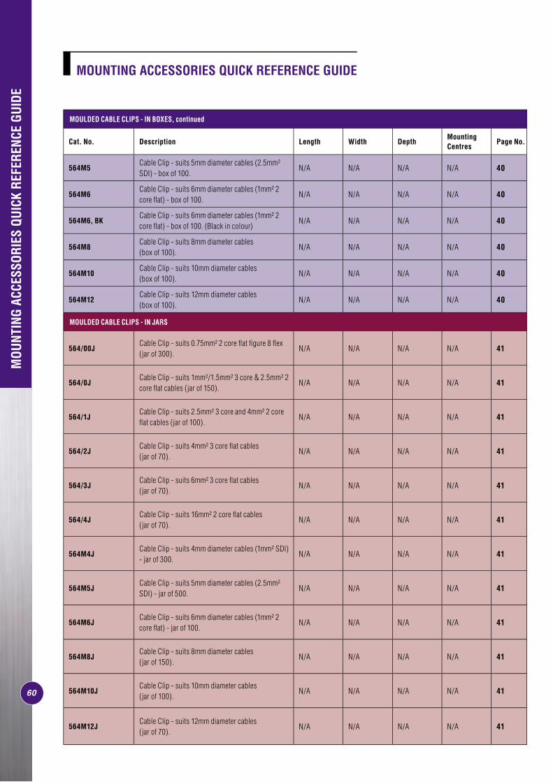
60
MOULDED CABLE CLIPS - IN BOXES, continued
Cat. No. Description Length Width DepthMounting Centres
Page No.
564M5Cable Clip - suits 5mm diameter cables (2.5mm² SDI) - box of 100.
N/A N/A N/A N/A 40
564M6Cable Clip - suits 6mm diameter cables (1mm² 2 core fl at) - box of 100.
N/A N/A N/A N/A 40
564M6, BKCable Clip - suits 6mm diameter cables (1mm² 2 core fl at) - box of 100. (Black in colour)
N/A N/A N/A N/A 40
564M8Cable Clip - suits 8mm diameter cables (box of 100).
N/A N/A N/A N/A 40
564M10Cable Clip - suits 10mm diameter cables (box of 100).
N/A N/A N/A N/A 40
564M12Cable Clip - suits 12mm diameter cables (box of 100).
N/A N/A N/A N/A 40
MOULDED CABLE CLIPS - IN JARS
564/00JCable Clip - suits 0.75mm² 2 core fl at fi gure 8 fl ex (jar of 300).
N/A N/A N/A N/A 41
564/0JCable Clip - suits 1mm²/1.5mm² 3 core & 2.5mm² 2 core fl at cables (jar of 150).
N/A N/A N/A N/A 41
564/1JCable Clip - suits 2.5mm² 3 core and 4mm² 2 core fl at cables (jar of 100).
N/A N/A N/A N/A 41
564/2JCable Clip - suits 4mm² 3 core fl at cables (jar of 70).
N/A N/A N/A N/A 41
564/3JCable Clip - suits 6mm² 3 core fl at cables (jar of 70).
N/A N/A N/A N/A 41
564/4JCable Clip - suits 16mm² 2 core fl at cables (jar of 70).
N/A N/A N/A N/A 41
564M4JCable Clip - suits 4mm diameter cables (1mm² SDI) - jar of 300.
N/A N/A N/A N/A 41
564M5JCable Clip - suits 5mm diameter cables (2.5mm² SDI) - jar of 500.
N/A N/A N/A N/A 41
564M6JCable Clip - suits 6mm diameter cables (1mm² 2 core fl at) - jar of 100.
N/A N/A N/A N/A 41
564M8JCable Clip - suits 8mm diameter cables (jar of 150).
N/A N/A N/A N/A 41
564M10JCable Clip - suits 10mm diameter cables (jar of 100).
N/A N/A N/A N/A 41
564M12JCable Clip - suits 12mm diameter cables (jar of 70).
N/A N/A N/A N/A 41
MOU
NTIN
G AC
CESS
ORIE
S QU
ICK
REFE
RENC
E GU
IDE
MOUNTING ACCESSORIES QUICK REFERENCE GUIDE
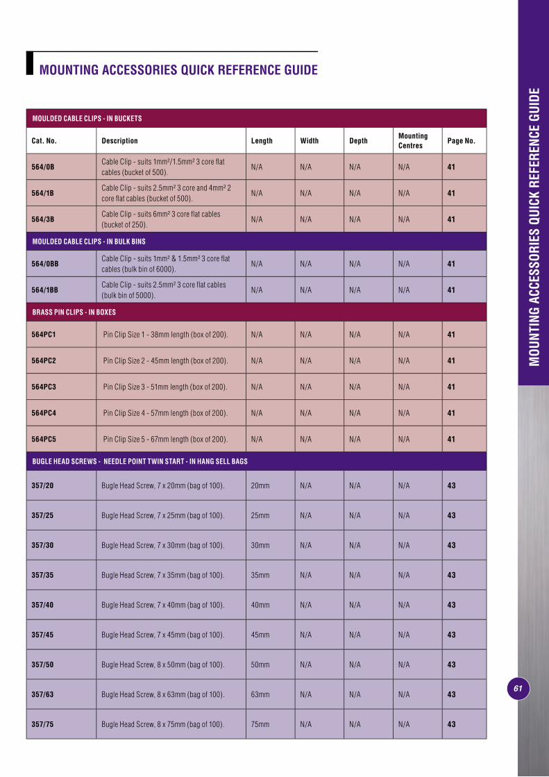
MOULDED CABLE CLIPS - IN BUCKETS
Cat. No. Description Length Width DepthMounting Centres
Page No.
564/0BCable Clip - suits 1mm²/1.5mm² 3 core fl at cables (bucket of 500).
N/A N/A N/A N/A 41
564/1BCable Clip - suits 2.5mm² 3 core and 4mm² 2 core fl at cables (bucket of 500).
N/A N/A N/A N/A 41
564/3BCable Clip - suits 6mm² 3 core fl at cables (bucket of 250).
N/A N/A N/A N/A 41
MOULDED CABLE CLIPS - IN BULK BINS
564/0BBCable Clip - suits 1mm² & 1.5mm² 3 core fl at cables (bulk bin of 6000).
N/A N/A N/A N/A 41
564/1BBCable Clip - suits 2.5mm² 3 core fl at cables (bulk bin of 5000).
N/A N/A N/A N/A 41
BRASS PIN CLIPS - IN BOXES
564PC1 Pin Clip Size 1 - 38mm length (box of 200). N/A N/A N/A N/A 41
564PC2 Pin Clip Size 2 - 45mm length (box of 200). N/A N/A N/A N/A 41
564PC3 Pin Clip Size 3 - 51mm length (box of 200). N/A N/A N/A N/A 41
564PC4 Pin Clip Size 4 - 57mm length (box of 200). N/A N/A N/A N/A 41
564PC5 Pin Clip Size 5 - 67mm length (box of 200). N/A N/A N/A N/A 41
BUGLE HEAD SCREWS - NEEDLE POINT TWIN START - IN HANG SELL BAGS
357/20 Bugle Head Screw, 7 x 20mm (bag of 100). 20mm N/A N/A N/A 43
357/25 Bugle Head Screw, 7 x 25mm (bag of 100). 25mm N/A N/A N/A 43
357/30 Bugle Head Screw, 7 x 30mm (bag of 100). 30mm N/A N/A N/A 43
357/35 Bugle Head Screw, 7 x 35mm (bag of 100). 35mm N/A N/A N/A 43
357/40 Bugle Head Screw, 7 x 40mm (bag of 100). 40mm N/A N/A N/A 43
357/45 Bugle Head Screw, 7 x 45mm (bag of 100). 45mm N/A N/A N/A 43
357/50 Bugle Head Screw, 8 x 50mm (bag of 100). 50mm N/A N/A N/A 43
357/63 Bugle Head Screw, 8 x 63mm (bag of 100). 63mm N/A N/A N/A 43
357/75 Bugle Head Screw, 8 x 75mm (bag of 100). 75mm N/A N/A N/A 43
MOUNTING ACCESSORIES QUICK REFERENCE GUIDE
61
MOU
NTIN
G AC
CESS
ORIE
S QU
ICK
REFE
RENC
E GU
IDE
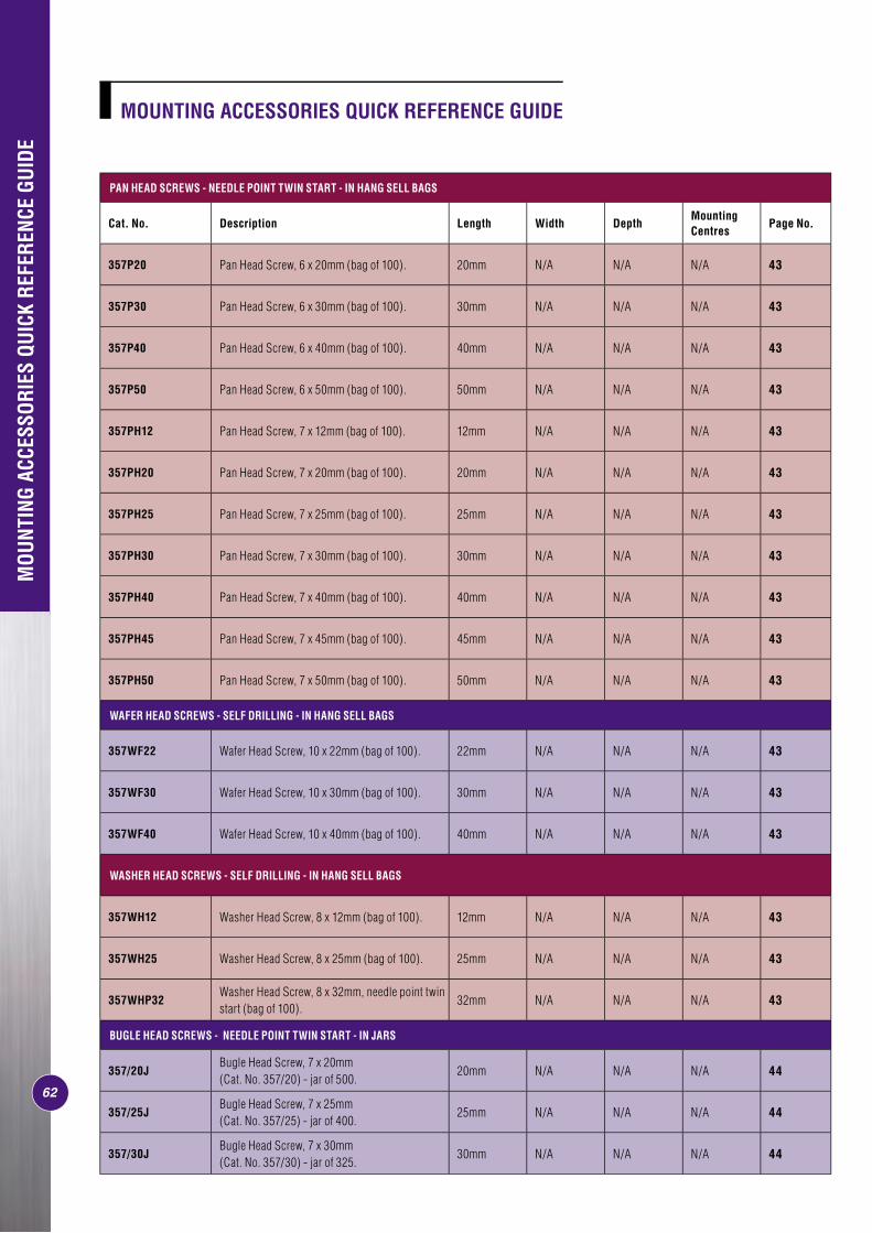
PAN HEAD SCREWS - NEEDLE POINT TWIN START - IN HANG SELL BAGS
Cat. No. Description Length Width DepthMounting Centres
Page No.
357P20 Pan Head Screw, 6 x 20mm (bag of 100). 20mm N/A N/A N/A 43
357P30 Pan Head Screw, 6 x 30mm (bag of 100). 30mm N/A N/A N/A 43
357P40 Pan Head Screw, 6 x 40mm (bag of 100). 40mm N/A N/A N/A 43
357P50 Pan Head Screw, 6 x 50mm (bag of 100). 50mm N/A N/A N/A 43
357PH12 Pan Head Screw, 7 x 12mm (bag of 100). 12mm N/A N/A N/A 43
357PH20 Pan Head Screw, 7 x 20mm (bag of 100). 20mm N/A N/A N/A 43
357PH25 Pan Head Screw, 7 x 25mm (bag of 100). 25mm N/A N/A N/A 43
357PH30 Pan Head Screw, 7 x 30mm (bag of 100). 30mm N/A N/A N/A 43
357PH40 Pan Head Screw, 7 x 40mm (bag of 100). 40mm N/A N/A N/A 43
357PH45 Pan Head Screw, 7 x 45mm (bag of 100). 45mm N/A N/A N/A 43
357PH50 Pan Head Screw, 7 x 50mm (bag of 100). 50mm N/A N/A N/A 43
WAFER HEAD SCREWS - SELF DRILLING - IN HANG SELL BAGS
357WF22 Wafer Head Screw, 10 x 22mm (bag of 100). 22mm N/A N/A N/A 43
357WF30 Wafer Head Screw, 10 x 30mm (bag of 100). 30mm N/A N/A N/A 43
357WF40 Wafer Head Screw, 10 x 40mm (bag of 100). 40mm N/A N/A N/A 43
WASHER HEAD SCREWS - SELF DRILLING - IN HANG SELL BAGS
357WH12 Washer Head Screw, 8 x 12mm (bag of 100). 12mm N/A N/A N/A 43
357WH25 Washer Head Screw, 8 x 25mm (bag of 100). 25mm N/A N/A N/A 43
357WHP32Washer Head Screw, 8 x 32mm, needle point twin start (bag of 100).
32mm N/A N/A N/A 43
BUGLE HEAD SCREWS - NEEDLE POINT TWIN START - IN JARS
357/20JBugle Head Screw, 7 x 20mm (Cat. No. 357/20) - jar of 500.
20mm N/A N/A N/A 44
357/25JBugle Head Screw, 7 x 25mm (Cat. No. 357/25) - jar of 400.
25mm N/A N/A N/A 44
357/30JBugle Head Screw, 7 x 30mm (Cat. No. 357/30) - jar of 325.
30mm N/A N/A N/A 44
MOUNTING ACCESSORIES QUICK REFERENCE GUIDE
62
MOU
NTIN
G AC
CESS
ORIE
S QU
ICK
REFE
RENC
E GU
IDE
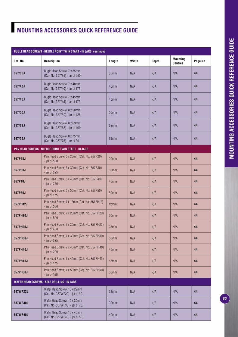
63
BUGLE HEAD SCREWS - NEEDLE POINT TWIN START - IN JARS, continued
Cat. No. Description Length Width DepthMounting Centres
Page No.
357/35JBugle Head Screw, 7 x 35mm (Cat. No. 357/35) - jar of 250.
35mm N/A N/A N/A 44
357/40JBugle Head Screw, 7 x 40mm (Cat. No. 357/40) - jar of 175.
40mm N/A N/A N/A 44
357/45JBugle Head Screw, 7 x 45mm (Cat. No. 357/45) - jar of 175.
45mm N/A N/A N/A 44
357/50JBugle Head Screw, 8 x 50mm (Cat. No. 357/50) - jar of 125.
50mm N/A N/A N/A 44
357/63JBugle Head Screw, 8 x 63mm (Cat. No. 357/63) - jar of 100.
63mm N/A N/A N/A 44
357/75JBugle Head Screw, 8 x 75mm (Cat. No. 357/75) - jar of 80.
75mm N/A N/A N/A 44
PAN HEAD SCREWS - NEEDLE POINT TWIN START - IN JARS
357P20JPan Head Screw, 6 x 20mm (Cat. No. 357P20) - jar of 500.
20mm N/A N/A N/A 44
357P30JPan Head Screw, 6 x 30mm (Cat. No. 357P30) - jar of 325.
30mm N/A N/A N/A 44
357P40JPan Head Screw, 6 x 40mm (Cat. No. 357P40) - jar of 250.
40mm N/A N/A N/A 44
357P50JPan Head Screw, 6 x 50mm (Cat. No. 357P50) - jar of 175.
50mm N/A N/A N/A 44
357PH12JPan Head Screw, 7 x 12mm (Cat. No. 357PH12) - jar of 500.
12mm N/A N/A N/A 44
357PH20JPan Head Screw, 7 x 20mm (Cat. No. 357PH20) - jar of 500.
20mm N/A N/A N/A 44
357PH25JPan Head Screw, 7 x 25mm (Cat. No. 357PH25) - jar of 400.
25mm N/A N/A N/A 44
357PH30JPan Head Screw, 7 x 30mm (Cat. No. 357PH30) - jar of 325.
30mm N/A N/A N/A 44
357PH40JPan Head Screw, 7 x 40mm (Cat. No. 357PH40) - jar of 200.
40mm N/A N/A N/A 44
357PH45JPan Head Screw, 7 x 45mm (Cat. No. 357PH45) - jar of 175.
45mm N/A N/A N/A 44
357PH50JPan Head Screw, 7 x 50mm (Cat. No. 357PH50) - jar of 150.
50mm N/A N/A N/A 44
WAFER HEAD SCREWS - SELF DRILLING - IN JARS
357WF22JWafer Head Screw, 10 x 22mm (Cat. No. 357WF22) - jar of 90.
22mm N/A N/A N/A 44
357WF30JWafer Head Screw, 10 x 30mm (Cat. No. 357WF30) - jar of 70.
30mm N/A N/A N/A 44
357WF40JWafer Head Screw, 10 x 40mm (Cat. No. 357WF40) - jar of 50.
40mm N/A N/A N/A 44
MOUNTING ACCESSORIES QUICK REFERENCE GUIDE
MOU
NTIN
G AC
CESS
ORIE
S QU
ICK
REFE
RENC
E GU
IDE
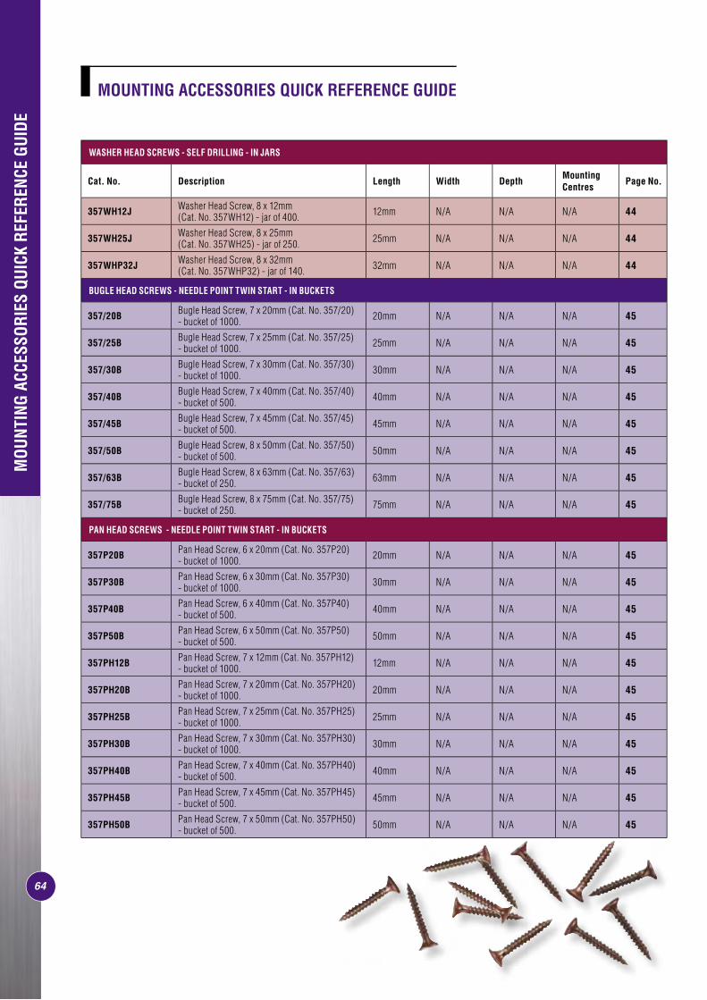
2005
MOU
NTIN
G AC
CESS
ORY
PROD
UCT
LIST
ING
MOUNTING ACCESSORIES QUICK REFERENCE GUIDE
MOU
NTIN
G AC
CESS
ORIE
S QU
ICK
REFE
RENC
E GU
IDE
64
WASHER HEAD SCREWS - SELF DRILLING - IN JARS
Cat. No. Description Length Width DepthMounting Centres
Page No.
357WH12J Washer Head Screw, 8 x 12mm (Cat. No. 357WH12) - jar of 400. 12mm N/A N/A N/A 44
357WH25J Washer Head Screw, 8 x 25mm (Cat. No. 357WH25) - jar of 250. 25mm N/A N/A N/A 44
357WHP32J Washer Head Screw, 8 x 32mm (Cat. No. 357WHP32) - jar of 140. 32mm N/A N/A N/A 44
BUGLE HEAD SCREWS - NEEDLE POINT TWIN START - IN BUCKETS
357/20B Bugle Head Screw, 7 x 20mm (Cat. No. 357/20) - bucket of 1000. 20mm N/A N/A N/A 45
357/25B Bugle Head Screw, 7 x 25mm (Cat. No. 357/25) - bucket of 1000. 25mm N/A N/A N/A 45
357/30B Bugle Head Screw, 7 x 30mm (Cat. No. 357/30) - bucket of 1000. 30mm N/A N/A N/A 45
357/40B Bugle Head Screw, 7 x 40mm (Cat. No. 357/40) - bucket of 500. 40mm N/A N/A N/A 45
357/45B Bugle Head Screw, 7 x 45mm (Cat. No. 357/45) - bucket of 500. 45mm N/A N/A N/A 45
357/50B Bugle Head Screw, 8 x 50mm (Cat. No. 357/50) - bucket of 500. 50mm N/A N/A N/A 45
357/63B Bugle Head Screw, 8 x 63mm (Cat. No. 357/63) - bucket of 250. 63mm N/A N/A N/A 45
357/75B Bugle Head Screw, 8 x 75mm (Cat. No. 357/75) - bucket of 250. 75mm N/A N/A N/A 45
PAN HEAD SCREWS - NEEDLE POINT TWIN START - IN BUCKETS
357P20B Pan Head Screw, 6 x 20mm (Cat. No. 357P20) - bucket of 1000. 20mm N/A N/A N/A 45
357P30B Pan Head Screw, 6 x 30mm (Cat. No. 357P30) - bucket of 1000. 30mm N/A N/A N/A 45
357P40B Pan Head Screw, 6 x 40mm (Cat. No. 357P40) - bucket of 500. 40mm N/A N/A N/A 45
357P50B Pan Head Screw, 6 x 50mm (Cat. No. 357P50) - bucket of 500. 50mm N/A N/A N/A 45
357PH12B Pan Head Screw, 7 x 12mm (Cat. No. 357PH12) - bucket of 1000. 12mm N/A N/A N/A 45
357PH20B Pan Head Screw, 7 x 20mm (Cat. No. 357PH20) - bucket of 1000. 20mm N/A N/A N/A 45
357PH25B Pan Head Screw, 7 x 25mm (Cat. No. 357PH25) - bucket of 1000. 25mm N/A N/A N/A 45
357PH30B Pan Head Screw, 7 x 30mm (Cat. No. 357PH30) - bucket of 1000. 30mm N/A N/A N/A 45
357PH40B Pan Head Screw, 7 x 40mm (Cat. No. 357PH40) - bucket of 500. 40mm N/A N/A N/A 45
357PH45B Pan Head Screw, 7 x 45mm (Cat. No. 357PH45) - bucket of 500. 45mm N/A N/A N/A 45
357PH50B Pan Head Screw, 7 x 50mm (Cat. No. 357PH50) - bucket of 500. 50mm N/A N/A N/A 45
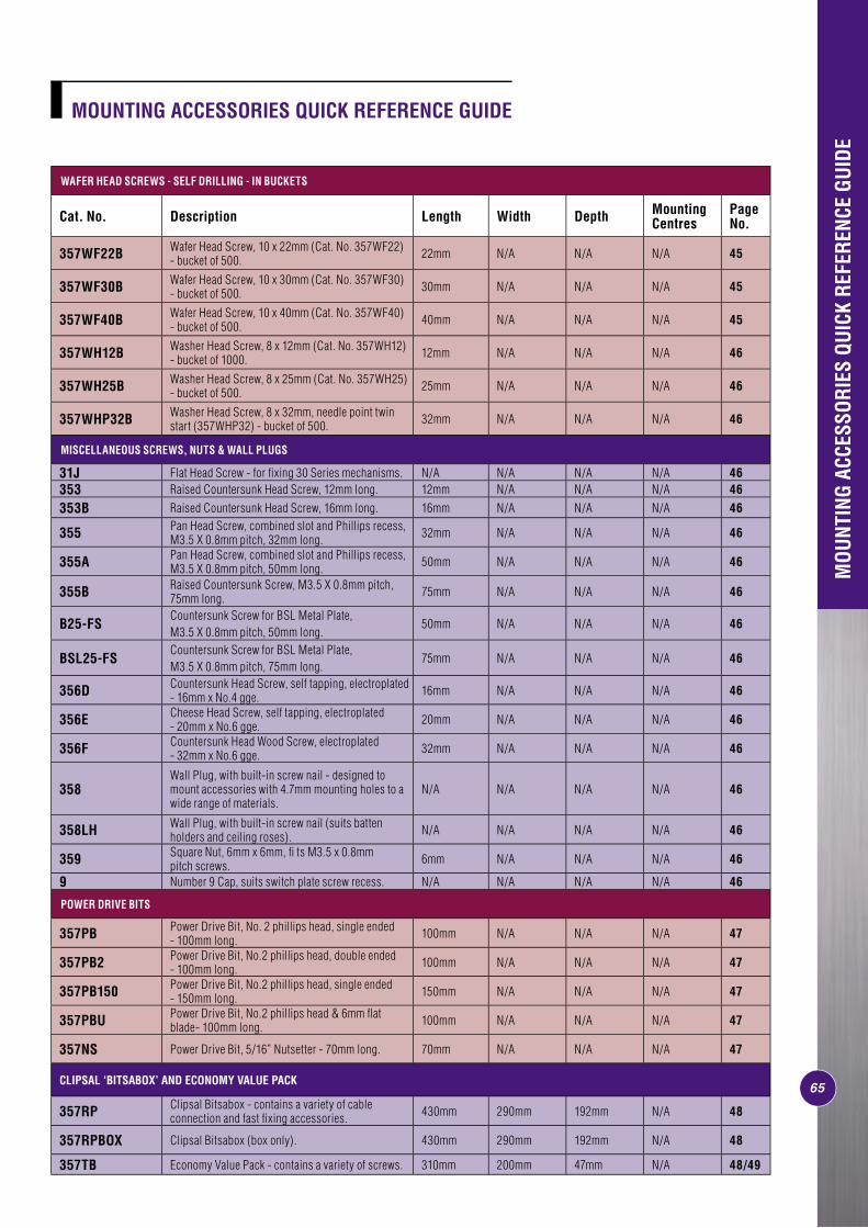
MOU
NTIN
G AC
CESS
ORIE
S QU
ICK
REFE
RENC
E GU
IDE
SWITCHES
Page No.
Cat No.
30, 30D,
30/15, 39,
30DD 32A 33A 34A 30T 32TA 33TA31BA 32BA
31BLA 32BLA
31BMF 32BMF
35BMF, 16/2MF,
16/2MFD, 16/2MF1510
31VA,31HA,32VA,32HA,33VA,33HA, 34VA,34HA, 35VA,36VA,
31VHWP, 36VKT3N, 36VKT3NX
36VKT4, 36VKT4X
31/2VA 32/2VA 33/2VA 31/2VX
34/2VA, 35/2VA, 36/2VA, 37/2VA, 38/2VA, 39/2VA 31/3VX 31VR 31VTO 31VCS
FIR
E R
ATED
W
ALL
BOXE
S Pg. 30 157/1F NS1 NS2 NS3 NS4 NS5 NS6 NS7 NS1 NS8 NS8 NS9 YES NS NS NS10 NS11 YES YES
Pg. 32 F157/1 NS1 NS2 NS3 NS4 NS5 NS6 NS7 NS1 NS8 NS8 NS9 YES NS NS NS10 NS11 YES YES
Pg. 30 157/2F NS1 NS2 NS3 NS4 NS5 NS6 NS7 NS1 NS8 NS8 NS9 NS12 YES YES NS10 NS11 NS12 NS12
ENCL
OSU
RES Pg. 39 224/1 NS1 NS2 NS3 NS4 NS5 NS6 NS7 NS1 NS8 NS8 NS9 YES NS NS NS10 NS11 YES AS
Pg. 39 223H NS1 NS2 NS3 NS4 NS5 NS6 NS7 NS1 NS8 NS8 NS9 Y1 NS NS NS10 NS11 YES AS
Pg. 39 255 NS1 NS2 NS3 NS4 NS5 NS6 NS7 YES YES NS8 NS9 YES NS NS NS10 NS11 YES AS
JUN
CTIO
N BO
XES Pg. 38 240 Series NS1 NS2 NS3 NS4 NS5 NS6 NS7 NS1 NS8 NS8 NS9 NS12 NS NS NS10 YES NS12 NS12
Pg. 38 T240 Series NS1 NS2 NS3 NS4 NS5 NS6 NS7 NS1 NS8 NS8 NS9 NS12 NS NS NS10 YES NS12 NS12
Pg. 38 SC240 Series NS1 NS2 NS3 NS4 NS5 NS6 NS7 NS1 NS8 NS8 NS9 NS12 NS NS NS10 YES NS12 NS12
ELECTRONIC PRODUCTS
Page No.
Cat No.
32E450L, 32E450T, 32E500F
31E800T, 31E1000L,
31VETF
31VETR, 31VETR3, 31VSSR
319, 319RA, 319N, 19HP 319X
TC15/24, TC15/15/24, TC15/15/7D
TC32V1, TC32V24, TC32V7D
15/15EL10, 15/15EL30,
25EL10,25EL30
15XRZ,15X15RZ 25SF 727
727V, 727H
FIR
E R
ATED
W
ALL
BOXE
S Pg. 30 157/1F YES YES X5 YES YES NS6 YES YES X5 YES NS17 NS18
Pg. 32 F157/1 X5 YES X5 YES YES NS6 YES YES X5 YES NS17 NS18
Pg. 30 157/2F NS12 NS12 NS12 NS12 NS12 NS6 NS12 NS12 NS12 NS12 NS17 NS18
ENCL
OSU
RES Pg. 39 224/1 YES YES YES YES YES NS6 YES N6 YES T NS17 NS18
Pg. 39 223H Y4 Y4 Y4 Y3 Y4 NS6 Y4 N3 N3 Y3 NS17 NS18
Pg. 39 255 YES YES YES YES YES NS6 Y7 Y7 Y YES NS17 NS18
JUN
CTIO
N BO
XES Pg. 38 240 Series NS12 NS12 NS12 NS12 NS12 NS6 NS12 NS12 NS12 NS12 NS17 NS18
Pg. 38 T240 Series NS12 NS12 NS12 NS12 NS12 NS6 NS12 NS12 NS12 NS12 NS17 NS18
Pg. 38 SC240 Series NS12 NS12 NS12 NS12 NS12 NS6 NS12 NS12 NS12 NS12 NS17 NS18
7170
SOCKET OUTLETS
Page No.
Cat No.
10,10D,
10DS,10DN, 10DLS,10D15S,
20, 20D,
20DS,20DN, 20DLS,
15,15S,15N, 15D,
15D15,15DN, 15/15,
15/15S, 15/15N,
15L,15LN,15X,
15XX,25,
25L,25X,
25XS, 25XA,
25XAN,25XD,25S, 25N,25D,
25D15, 25/15,
25/15S, 25/15N,25/1510, 42/20,42/20N 15DD 15DX
15V, 15VS, 15VX,
15VXN, 15VXX, 15V15,
25V, 25VXA
15/2V, 15/2VS, 15/2VN, 15D2V,
15/2, 15/2S, 15/2N, 25/2V,
25/2VS, 25/2VN 15DD2V 40 14
16, 16N, 16F,
16/15
16/2, 16/2S, 16/2N, 16/2F 16X
23, 23X
FIR
E R
ATED
W
ALL
BOXE
S Pg. 30 157/1F YES YES YES YES YES NS NS3 NS3 YES NS13 NS14 NS15 NS16
Pg. 32 F157/1 YES YES YES YES YES NS NS3 NS3 YES NS13 NS14 NS15 NS16
Pg. 30 157/2F NS12 NS12 NS12 NS12 NS12 YES NS3 NS3 NS12 NS13 NS14 NS15 NS16
ENCL
OSU
RES Pg. 39 224/1 YES NS12 YES AS AS NS NS3 NS3 NS12 NS13 NS14 NS15 NS16
Pg. 39 223H Y1 NS12 NS AS AS NS NS3 NS3 NS12 NS13 NS14 NS15 NS16
Pg. 39 255 YES NS12 YES AS AS NS NS3 NS3 NS12 NS13 NS14 NS15 NS16
JUN
CTIO
N BO
XES
Pg. 38 240 Series NS12 NS12 NS12 NS12 NS12 NS NS3 NS3 NS12 NS13 NS14 NS15 NS16
Pg. 38 T240 Series NS12 NS12 NS12 NS12 NS12 NS NS3 NS3 NS12 NS13 NS14 NS15 NS16
Pg. 38 SC240 Series NS12 NS12 NS12 NS12 NS12 NS NS3 NS3 NS12 NS13 NS14 NS15 NS16
SWITCHES ELECTRONIC PRODUCTS
Page No.
Cat No. 2030 2032A
2033A, 2034A
2031VA, 2031HA, 2032VA, 2032HA, 2033VA, 2033HA, 2034VA, 2034HA, 2035HA, 2035VA,2036HA, 2036VA,
2031VXCB, 2036VKT3N,
2036VKT3NX, 2036VKT4,
2036VKT4X, 2031/45,
2031/45N, 2031D40, 2031D40N
2033CC1, 2033CC1N,
2033CC1NX, 2033CC1X, 2033CC2,
2033CC2X, 2036CC3N,
2033CC3NX, 2033CC4, 2033CC4X 2031VX 2031VCS
2031V66, 2031H66, 2032V66, 2032H66
2032E450L, 2032E450T, 2032E500F
2031E800T, 2031E1000L,
2031VETF2031VETR, 2031VETR3
MO
UN
TIN
G BL
OCK
S
Pg. 4 449AS NS1 NS2 NS4 Y1N Y1N N Y1N Y1Y10N Y3N Y4N Y4N
Pg. 4 449ASD NS1 NS2 NS4 YES YES YES YES Y1Y10 Y2 Y3 N12
Pg. 8 449A NS1 NS2 NS4 YES YES YES YES Y10 YES N3 N3
Pg. 38 238 NS1 NS2 NS4 N N N N Y12N N N N
Pg. 4 2000SMK NS1 NS2 NS4 YES YES YES YES Y11 YES Y3 Y3
Pg. 4 2449ASD NS1 NS2 NS4 YES YES YES YES Y11 YES Y3 Y3
Pg. 9 C2449ASD NS1 NS2 NS4 YES YES YES YES N11 Y2 Y3 N12
Pg. 38 900SPBP NS1 NS2 NS4 N N N N Y10N Y1N Y1N Y2N
Pg. 38 900SPMB NS1 NS2 NS4 N N N N Y12N N N N
Pg. 8 70/1 YES NS2 NS4 NS12 NS12 NS12 NS12 NS12 NS12 NS12 NS12
Pg. 8 70/2 NS1 YES NS4 NS12 NS12 NS12 NS12 NS12 NS12 NS12 NS12
Pg. 11 1920MB NS1 NS2 NS4 YES YES YES YES Y10 YES Y1 N13
WAL
L BR
ACKE
TS
AND
PLAT
ES
Pg. 19 155PRM NS1 NS2 NS4 Y1 Y1 YES Y1 Y1 Y4 Y5 Y4
Pg. 19 155P NS1 NS2 NS4 Y1 Y1 YES Y1 Y1 Y4 Y5 Y4
Pg. 18 155 NS1 NS2 NS4 Y1 Y1 YES Y1 Y1 Y4 Y5 Y4
Pg. 18 155NAR NS1 NS2 NS4 Y1 Y1 YES Y1 Y1 Y4 Y5 Y4
Pg. 20 2155PRM2 NS1 NS2 NS4 Y1 Y1 YES Y1 Y1 Y4 Y5 Y4
Pg. 20 2155PHRM2 NS1 NS2 NS4 Y1 Y1 YES Y1 Y1 Y4 Y5 Y4
Pg. 20 2155PRM3 NS1 NS2 NS4 Y1 Y1 YES Y1 Y1 Y4 Y5 Y4
Pg. 20 2155PHRM3 NS1 NS2 NS4 Y1 Y1 YES Y1 Y1 Y4 Y5 Y4
Pg. 20 2155PRM4 NS1 NS2 NS4 Y1 Y1 YES Y1 Y1 Y4 Y5 Y4
WAL
L CL
IPS
Pg. 17 154 NS1 NS2 NS4 Y1 Y1 YES Y1 Y1 Y4 Y5 Y4
Pg. 17 154RM NS1 NS2 NS4 Y1 Y1 YES Y1 Y1 Y4 Y5 Y4
Pg. 20 2154/2 NS1 NS2 NS4 Y1 Y1 YES Y1 Y1 Y4 Y5 Y4
Pg. 20 2154H2 NS1 NS2 NS4 Y1 Y1 YES Y1 Y1 Y4 Y5 Y4
Pg. 20 2154/3 NS1 NS2 NS4 Y1 Y1 YES Y1 Y1 Y4 Y5 Y4
Pg. 20 2154H3 NS1 NS2 NS4 Y1 Y1 YES Y1 Y1 Y4 Y5 Y4
Pg. 20 2154/4 NS1 NS2 NS4 Y1 Y1 YES Y1 Y1 Y4 Y5 Y4
STAN
DARD
SER
IES
CROS
S RE
FERE
NCE
CHAR
T
SERI
ES 2
000
CROS
S RE
FERE
NCE
CHAR
T
72
YOU WILL FIND KEY TO THIS TABLE ON PAGES 88-89YOU WILL FIND KEY TO THIS TABLE ON PAGES 88-89 YOU WILL FIND KEY TO THIS TABLE ON PAGES 88-89
65
WAFER HEAD SCREWS - SELF DRILLING - IN BUCKETS
Cat. No. Description Length Width Depth Mounting Centres
Page No.
357WF22B Wafer Head Screw, 10 x 22mm (Cat. No. 357WF22)- bucket of 500. 22mm N/A N/A N/A 45
357WF30B Wafer Head Screw, 10 x 30mm (Cat. No. 357WF30)- bucket of 500. 30mm N/A N/A N/A 45
357WF40B Wafer Head Screw, 10 x 40mm (Cat. No. 357WF40)- bucket of 500. 40mm N/A N/A N/A 45
357WH12B Washer Head Screw, 8 x 12mm (Cat. No. 357WH12) - bucket of 1000. 12mm N/A N/A N/A 46
357WH25B Washer Head Screw, 8 x 25mm (Cat. No. 357WH25) - bucket of 500. 25mm N/A N/A N/A 46
357WHP32B Washer Head Screw, 8 x 32mm, needle point twinstart (357WHP32) - bucket of 500. 32mm N/A N/A N/A 46
MISCELLANEOUS SCREWS, NUTS & WALL PLUGS
31J Flat Head Screw - for fi xing 30 Series mechanisms. N/A N/A N/A N/A 46353 Raised Countersunk Head Screw, 12mm long. 12mm N/A N/A N/A 46353B Raised Countersunk Head Screw, 16mm long. 16mm N/A N/A N/A 46
355 Pan Head Screw, combined slot and Phillips recess, M3.5 X 0.8mm pitch, 32mm long. 32mm N/A N/A N/A 46
355A Pan Head Screw, combined slot and Phillips recess, M3.5 X 0.8mm pitch, 50mm long. 50mm N/A N/A N/A 46
355B Raised Countersunk Screw, M3.5 X 0.8mm pitch, 75mm long. 75mm N/A N/A N/A 46
B25-FSCountersunk Screw for BSL Metal Plate, M3.5 X 0.8mm pitch, 50mm long.
50mm N/A N/A N/A 46
BSL25-FSCountersunk Screw for BSL Metal Plate, M3.5 X 0.8mm pitch, 75mm long.
75mm N/A N/A N/A 46
356D Countersunk Head Screw, self tapping, electroplated- 16mm x No.4 gge. 16mm N/A N/A N/A 46
356E Cheese Head Screw, self tapping, electroplated- 20mm x No.6 gge. 20mm N/A N/A N/A 46
356F Countersunk Head Wood Screw, electroplated- 32mm x No.6 gge. 32mm N/A N/A N/A 46
358Wall Plug, with built-in screw nail - designed tomount accessories with 4.7mm mounting holes to awide range of materials.
N/A N/A N/A N/A 46
358LH Wall Plug, with built-in screw nail (suits battenholders and ceiling roses). N/A N/A N/A N/A 46
359 Square Nut, 6mm x 6mm, fi ts M3.5 x 0.8mmpitch screws. 6mm N/A N/A N/A 46
9 Number 9 Cap, suits switch plate screw recess. N/A N/A N/A N/A 46
POWER DRIVE BITS
357PB Power Drive Bit, No. 2 phillips head, single ended- 100mm long. 100mm N/A N/A N/A 47
357PB2 Power Drive Bit, No.2 phillips head, double ended- 100mm long. 100mm N/A N/A N/A 47
357PB150 Power Drive Bit, No.2 phillips head, single ended- 150mm long. 150mm N/A N/A N/A 47
357PBU Power Drive Bit, No.2 phillips head & 6mm fl at blade- 100mm long. 100mm N/A N/A N/A 47
357NS Power Drive Bit, 5/16” Nutsetter - 70mm long. 70mm N/A N/A N/A 47
CLIPSAL ‘BITSABOX’ AND ECONOMY VALUE PACK
357RP Clipsal Bitsabox - contains a variety of cableconnection and fast fi xing accessories. 430mm 290mm 192mm N/A 48
357RPBOX Clipsal Bitsabox (box only). 430mm 290mm 192mm N/A 48
357TB Economy Value Pack - contains a variety of screws. 310mm 200mm 47mm N/A 48/49
MOUNTING ACCESSORIES QUICK REFERENCE GUIDE
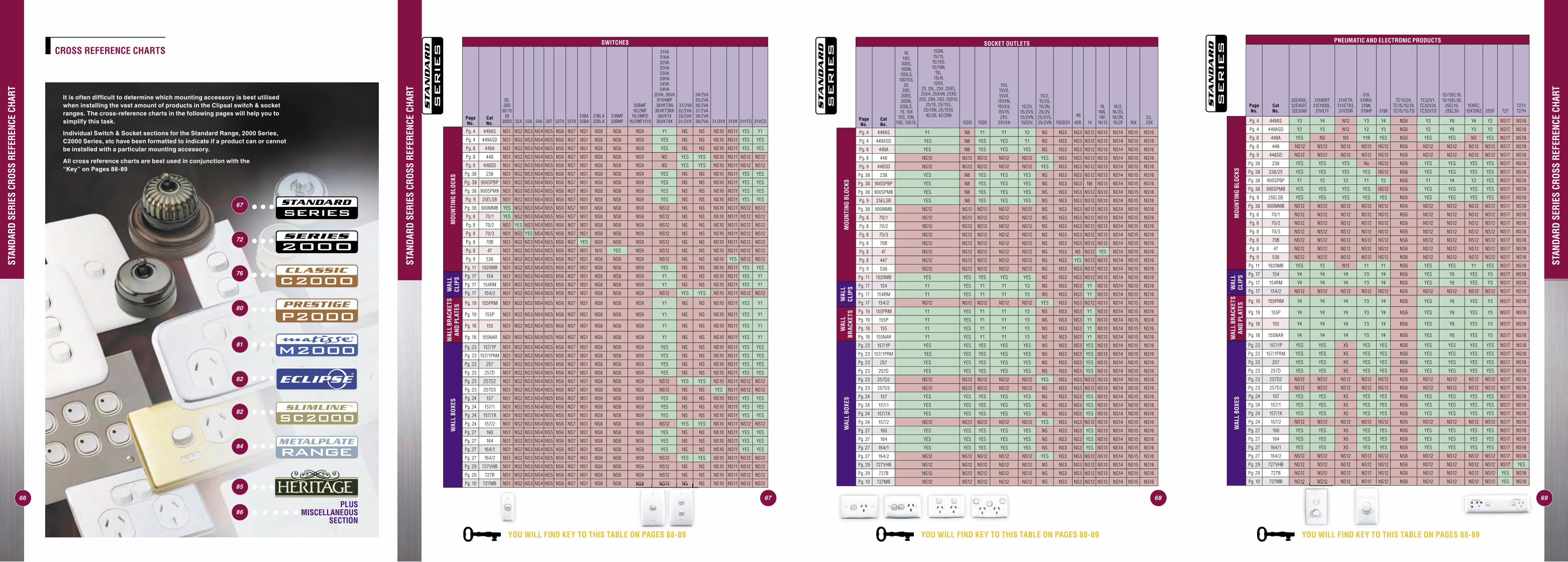
STAN
DARD
SER
IES
CROS
S RE
FERE
NCE
CHAR
T
SWITCHES
Page No.
Cat No.
30, 30D
30/15 39
30DD 32A 33A 34A 30T 32TA 33TA31BA32BA
31BLA 32BLA
31BMF 32BMF
35BMF 16/2MF
16/2MFD 16/2MF1510
31VA31HA 32VA32HA 33VA33HA 34VA34HA
35VA, 36VA 31VHWP 36VKT3N
36VKT3NX 36VKT4
36VKT4X
31/2VA 32/2VA 33/2VA 31/2VX
34/2VA 35/2VA 36/2VA 37/2VA 38/2VA 39/2VA 31/3VX 31VR 31VTO 31VCS
MO
UN
TIN
G BL
OCK
S
Pg. 4 449AS NS1 NS2 NS3 NS4 NS5 NS6 NS7 NS1 NS8 NS8 NS9 Y1 NS NS NS10 NS11 YES Y1
Pg. 4 449ASD NS1 NS2 NS3 NS4 NS5 NS6 NS7 NS1 NS8 NS8 NS9 YES NS NS NS10 NS11 YES YES
Pg. 8 449A NS1 NS2 NS3 NS4 NS5 NS6 NS7 NS1 NS8 NS8 NS9 YES NS NS NS10 NS11 YES YES
Pg. 8 448 NS1 NS2 NS3 NS4 NS5 NS6 NS7 NS1 NS8 NS8 NS9 NS YES YES NS10 NS11 NS12 NS12
Pg. 9 448SD NS1 NS2 NS3 NS4 NS5 NS6 NS7 NS1 NS8 NS8 NS9 NS YES YES NS10 NS11 NS12 NS12
Pg. 38 238 NS1 NS2 NS3 NS4 NS5 NS6 NS7 NS1 NS8 NS8 NS9 YES NS NS NS10 NS11 YES YES
Pg. 38 900SPBP NS1 NS2 NS3 NS4 NS5 NS6 NS7 NS1 NS8 NS8 NS9 YES NS NS NS10 NS11 YES YES
Pg. 38 900SPMB NS1 NS2 NS3 NS4 NS5 NS6 NS7 NS1 NS8 NS8 NS9 YES NS NS NS10 NS11 YES YES
Pg. 9 25ELSB NS1 NS2 NS3 NS4 NS5 NS6 NS7 NS1 NS8 NS8 NS9 YES NS NS NS10 NS11 YES YES
Pg. 38 900MMB YES NS2 NS3 NS4 NS5 NS6 NS7 NS1 NS8 NS8 NS9 NS12 NS NS NS10 NS11 NS12 NS12
Pg. 8 70/1 YES NS2 NS3 NS4 NS5 NS6 NS7 NS1 NS8 NS8 NS9 NS12 NS NS NS10 NS11 NS12 NS12
Pg. 8 70/2 NS1 YES NS3 NS4 NS5 NS6 NS7 NS1 NS8 NS8 NS9 NS12 NS NS NS10 NS11 NS12 NS12
Pg. 8 70/3 NS1 NS2 YES NS4 NS5 NS6 NS7 NS1 NS8 NS8 NS9 NS12 NS NS NS10 NS11 NS12 NS12
Pg. 8 70B NS1 NS2 NS3 NS4 NS5 NS6 NS7 YES NS8 NS8 NS9 NS12 NS NS NS10 NS11 NS12 NS12
Pg. 8 47 NS1 NS2 NS3 NS4 NS5 NS6 NS7 NS1 N10 YES NS9 NS12 NS NS NS10 NS11 NS12 NS12
Pg. 9 536 NS1 NS2 NS3 NS4 NS5 NS6 NS7 NS1 NS8 NS8 NS9 NS12 NS NS NS10 YES NS12 NS12
Pg. 11 1920MB NS1 NS2 NS3 NS4 NS5 NS6 NS7 NS1 NS8 NS8 NS9 YES NS NS NS10 NS11 YES YES
WAL
L CL
IPS Pg. 17 154 NS1 NS2 NS3 NS4 NS5 NS6 NS7 NS1 NS8 NS8 NS9 Y1 NS NS NS10 NS11 YES Y1
Pg. 17 154RM NS1 NS2 NS3 NS4 NS5 NS6 NS7 NS1 NS8 NS8 NS9 Y1 NS NS NS10 NS11 YES Y1
Pg. 17 154/2 NS1 NS2 NS3 NS4 NS5 NS6 NS7 NS1 NS8 NS8 NS9 NS12 YES YES NS10 NS11 NS12 NS12
WAL
L BR
ACKE
TS
AND
PLAT
ES
Pg. 19 155PRM NS1 NS2 NS3 NS4 NS5 NS6 NS7 NS1 NS8 NS8 NS9 Y1 NS NS NS10 NS11 YES Y1
Pg. 19 155P NS1 NS2 NS3 NS4 NS5 NS6 NS7 NS1 NS8 NS8 NS9 Y1 NS NS NS10 NS11 YES Y1
Pg. 18 155 NS1 NS2 NS3 NS4 NS5 NS6 NS7 NS1 NS8 NS8 NS9 Y1 NS NS NS10 NS11 YES Y1
Pg. 18 155NAR NS1 NS2 NS3 NS4 NS5 NS6 NS7 NS1 NS8 NS8 NS9 Y1 NS NS NS10 NS11 YES Y1
WAL
L BO
XES
Pg. 23 157/1P NS1 NS2 NS3 NS4 NS5 NS6 NS7 NS1 NS8 NS8 NS9 YES NS NS NS10 NS11 YES YES
Pg. 23 157/1PRM NS1 NS2 NS3 NS4 NS5 NS6 NS7 NS1 NS8 NS8 NS9 YES NS NS NS10 NS11 YES YES
Pg. 23 257 NS1 NS2 NS3 NS4 NS5 NS6 NS7 NS1 NS8 NS8 NS9 YES NS NS NS10 NS11 YES YES
Pg. 23 257D NS1 NS2 NS3 NS4 NS5 NS6 NS7 NS1 NS8 NS8 NS9 YES NS NS NS10 NS11 YES YES
Pg. 23 257D2 NS1 NS2 NS3 NS4 NS5 NS6 NS7 NS1 NS8 NS8 NS9 NS12 YES YES NS10 NS11 NS12 NS12
Pg. 23 257D3 NS1 NS2 NS3 NS4 NS5 NS6 NS7 NS1 NS8 NS8 NS9 NS12 NS NS YES NS11 NS12 NS12
Pg. 24 157 NS1 NS2 NS3 NS4 NS5 NS6 NS7 NS1 NS8 NS8 NS9 YES NS NS NS10 NS11 YES YES
Pg. 24 157/1 NS1 NS2 NS3 NS4 NS5 NS6 NS7 NS1 NS8 NS8 NS9 YES NS NS NS10 NS11 YES YES
Pg. 24 157/1X NS1 NS2 NS3 NS4 NS5 NS6 NS7 NS1 NS8 NS8 NS9 YES NS NS NS10 NS11 YES YES
Pg. 24 157/2 NS1 NS2 NS3 NS4 NS5 NS6 NS7 NS1 NS8 NS8 NS9 NS12 YES YES NS10 NS11 NS12 NS12
Pg. 27 160 NS1 NS2 NS3 NS4 NS5 NS6 NS7 NS1 NS8 NS8 NS9 YES NS NS NS10 NS11 YES YES
Pg. 27 164 NS1 NS2 NS3 NS4 NS5 NS6 NS7 NS1 NS8 NS8 NS9 YES NS NS NS10 NS11 YES YES
Pg. 27 164/1 NS1 NS2 NS3 NS4 NS5 NS6 NS7 NS1 NS8 NS8 NS9 YES NS NS NS10 NS11 YES YES
Pg. 27 164/2 NS1 NS2 NS3 NS4 NS5 NS6 NS7 NS1 NS8 NS8 NS9 NS12 YES YES NS10 NS11 NS12 NS12
Pg. 29 727VHB NS1 NS2 NS3 NS4 NS5 NS6 NS7 NS1 NS8 NS8 NS9 NS12 NS NS NS10 NS11 NS12 NS12
Pg. 29 727B NS1 NS2 NS3 NS4 NS5 NS6 NS7 NS1 NS8 NS8 NS9 NS12 NS NS NS10 NS11 NS12 NS12
Pg. 10 727MB NS1 NS2 NS3 NS4 NS5 NS6 NS7 NS1 NS8 NS8 NS9 NS12 NS NS NS10 NS11 NS12 NS12
STAN
DARD
SER
IES
CROS
S RE
FERE
NCE
CHAR
T
6867
SOCKET OUTLETS
Page No.
Cat No.
10, 10D,
10DS, 10DN, 10DLS, 10D15S,
20, 20D,
20DS, 20DN, 20DLS, 15, 15X
15S, 15N, 15D, 15D15,
15DN, 15/15,
15/15S, 15/15N,
15L, 15LN, 15XX,
25, 25L, 25X, 25XS, 25XA, 25XAN, 25XD
25S, 25N, 25D, 25D15, 25/15, 25/15S,
25/15N, 25/1510, 42/20, 42/20N
15DD 15DX
15V, 15VS, 15VX,
15VXN, 15VXX, 15V15,
25V, 25VXA
15/2V, 15/2VS, 15/2VN, 15D2V,
15/2, 15/2S, 15/2N, 25/2V,
25/2VS, 25/2VN 15DD2V
40
40D 14
16, 16N ,16F,
16/15
16/2, 16/2S, 16/2N, 16/2F 16X
23, 23X
MO
UN
TIN
G BL
OCK
S
Pg. 4 449AS Y1 N8 Y1 Y1 Y2 NS NS3 NS3 NS12 NS13 NS14 NS15 NS16
Pg. 4 449ASD YES N8 YES YES Y1 NS NS3 NS3 NS12 NS13 NS14 NS15 NS16
Pg. 8 449A YES N8 YES YES YES NS NS3 NS3 NS12 NS13 NS14 NS15 NS16
Pg. 8 448 NS12 NS12 NS12 NS12 NS12 YES NS3 NS3 NS12 NS13 NS14 NS15 NS16
Pg. 9 448SD NS12 NS12 NS12 NS12 NS12 YES NS3 NS3 NS12 NS13 NS14 NS15 NS16
Pg. 38 238 YES N8 YES YES YES NS NS3 NS3 NS12 NS13 NS14 NS15 NS16
Pg. 38 900SPBP YES N8 YES YES YES NS NS3 NS3 N8 NS13 NS14 NS15 NS16
Pg. 38 900SPMB YES N8 YES YES YES NS NS3 NS3 NS12 NS13 NS14 NS15 NS16
Pg. 9 25ELSB YES N8 YES YES YES NS NS3 NS3 NS12 NS13 NS14 NS15 NS16
Pg. 38 900MMB NS12 NS12 NS12 NS12 NS12 NS NS3 NS3 NS12 NS13 NS14 NS15 NS16
Pg. 8 70/1 NS12 NS12 NS12 NS12 NS12 NS NS3 NS3 NS12 NS13 NS14 NS15 NS16
Pg. 8 70/2 NS12 NS12 NS12 NS12 NS12 NS NS3 NS3 NS12 NS13 NS14 NS15 NS16
Pg. 8 70/3 NS12 NS12 NS12 NS12 NS12 NS NS3 NS3 NS12 NS13 NS14 NS15 NS16
Pg. 8 70B NS12 NS12 NS12 NS12 NS12 NS NS3 NS3 NS12 NS13 NS14 NS15 NS16
Pg. 8 47 NS12 NS12 NS12 NS12 NS12 NS NS3 NS NS12 YES NS14 NS15 NS16
Pg. 8 447 NS12 NS12 NS12 NS12 NS12 NS NS3 YES NS12 NS13 NS14 NS15 NS16
Pg. 9 536 NS12 NS12 NS12 NS12 NS12 NS NS3 NS3 NS12 NS13 NS14 NS15 NS16
Pg. 11 1920MB YES YES YES YES YES NS NS3 NS3 NS12 NS13 NS14 NS15 NS16
WAL
L CL
IPS Pg. 17 154 Y1 YES Y1 Y1 Y3 NS NS3 NS3 Y1 NS13 NS14 NS15 NS16
Pg. 17 154RM Y1 YES Y1 Y1 Y3 NS NS3 NS3 Y1 NS13 NS14 NS15 NS16
Pg. 17 154/2 NS12 NS12 NS12 NS12 NS12 YES NS3 NS3 NS12 NS13 NS14 NS15 NS16
WAL
L BR
ACKE
TS Pg. 19 155PRM Y1 YES Y1 Y1 Y3 NS NS3 NS3 Y1 NS13 NS14 NS15 NS16
Pg. 19 155P Y1 YES Y1 Y1 Y3 NS NS3 NS3 Y1 NS13 NS14 NS15 NS16
Pg. 18 155 Y1 YES Y1 Y1 Y3 NS NS3 NS3 Y1 NS13 NS14 NS15 NS16
Pg. 18 155NAR Y1 YES Y1 Y1 Y3 NS NS3 NS3 Y1 NS13 NS14 NS15 NS16
WAL
L BO
XES
Pg. 23 157/1P YES YES YES YES YES NS NS3 NS3 YES NS13 NS14 NS15 NS16
Pg. 23 157/1PRM YES YES YES YES YES NS NS3 NS3 YES NS13 NS14 NS15 NS16
Pg. 23 257 YES YES YES YES YES NS NS3 NS3 YES NS13 NS14 NS15 NS16
Pg. 23 257D YES YES YES YES YES NS NS3 NS3 YES NS13 NS14 NS15 NS16
Pg. 23 257D2 NS12 NS12 NS12 NS12 NS12 YES NS3 NS3 NS12 NS13 NS14 NS15 NS16
Pg. 23 257D3 NS12 NS12 NS12 NS12 NS12 NS NS3 NS3 NS12 NS13 NS14 NS15 NS16
Pg. 24 157 YES YES YES YES YES NS NS3 NS3 YES NS13 NS14 NS15 NS16
Pg. 24 157/1 YES YES YES YES YES NS NS3 NS3 YES NS13 NS14 NS15 NS16
Pg. 24 157/1X YES YES YES YES YES NS NS3 NS3 YES NS13 NS14 NS15 NS16
Pg. 24 157/2 NS12 NS12 NS12 NS12 NS12 YES NS3 NS3 NS12 NS13 NS14 NS15 NS16
Pg. 27 160 YES YES YES YES YES NS NS3 NS3 YES NS13 NS14 NS15 NS16
Pg. 27 164 YES YES YES YES YES NS NS3 NS3 YES NS13 NS14 NS15 NS16
Pg. 27 164/1 YES YES YES YES YES NS NS3 NS3 YES NS13 NS14 NS15 NS16
Pg. 27 164/2 NS12 NS12 NS12 NS12 NS12 YES NS3 NS3 NS12 NS13 NS14 NS15 NS16
Pg. 29 727VHB NS12 NS12 NS12 NS12 NS12 NS NS3 NS3 NS12 NS13 NS14 NS15 NS16
Pg. 29 727B NS12 NS12 NS12 NS12 NS12 NS NS3 NS3 NS12 NS13 NS14 NS15 NS16
Pg. 10 727MB NS12 NS12 NS12 NS12 NS12 NS NS3 NS3 NS12 NS13 NS14 NS15 NS16
PNEUMATIC AND ELECTRONIC PRODUCTS
Page No.
Cat No.
32E450L, 32E450T, 32E500F
31E800T, 31E1000L,
31VETF
31VETR, 31VETR3, 31VSSR
319, 319RA, 319N, 319HP 319X
TC15/24, TC15/15/24, TC15/15/7D
TC32V1, TC32V24, TC32V7D
15/15EL10, 15/15EL30,
25EL10, 25EL30
15XRZ,15X15RZ 25SF 727
727V 727H
MO
UN
TIN
G BL
OCK
S
Pg. 4 449AS Y3 Y4 N12 Y3 Y4 NS6 Y3 Y6 Y4 Y2 NS17 NS18
Pg. 4 449ASD Y2 Y3 N12 Y2 Y3 NS6 Y2 Y6 Y3 Y2 NS17 NS18
Pg. 8 449A YES N3 N3 Y1R YES NS6 YES YES N3 YES NS17 NS18
Pg. 8 448 NS12 NS12 NS12 NS12 NS12 NS6 NS12 NS12 NS12 NS12 NS17 NS18
Pg. 9 448SD NS12 NS12 NS12 NS12 NS12 NS6 NS12 NS12 NS12 NS12 NS17 NS18
Pg. 38 238 YES YES YES No NS12 NS6 YES YES YES YES NS17 NS18
Pg. 38 238/25 YES YES YES YES NS12 NS6 YES YES YES YES NS17 NS18
Pg. 38 900SPBP Y1 Y2 Y2 Y1 Y2 NS6 Y1 Y4 Y2 YES NS17 NS18
Pg. 38 900SPMB YES YES YES YES NS12 NS6 YES YES YES YES NS17 NS18
Pg. 9 25ELSB YES YES YES YES YES NS6 YES YES YES YES NS17 NS18
Pg. 38 900MMB NS12 NS12 NS12 NS12 NS12 NS6 NS12 NS12 NS12 NS12 NS17 NS18
Pg. 8 70/1 NS12 NS12 NS12 NS12 NS12 NS6 NS12 NS12 NS12 NS12 NS17 NS18
Pg. 8 70/2 NS12 NS12 NS12 NS12 NS12 NS6 NS12 NS12 NS12 NS12 NS17 NS18
Pg. 8 70/3 NS12 NS12 NS12 NS12 NS12 NS6 NS12 NS12 NS12 NS12 NS17 NS18
Pg. 8 70B NS12 NS12 NS12 NS12 NS12 NS6 NS12 NS12 NS12 NS12 NS17 NS18
Pg. 8 47 NS12 NS12 NS12 NS12 NS12 NS6 NS12 NS12 NS12 NS12 NS17 NS18
Pg. 9 536 NS12 NS12 NS12 NS12 NS12 NS6 NS12 NS12 NS12 NS12 NS17 NS18
Pg. 11 1920MB YES Y2 N13 Y1 Y1 NS6 YES YES Y1 YES NS17 NS18
WAL
L CL
IPS Pg. 17 154 Y4 Y4 Y4 Y3 Y4 NS6 YES Y6 YES Y3 NS17 NS18
Pg. 17 154RM Y4 Y4 Y4 Y3 Y4 NS6 YES Y6 YES Y3 NS17 NS18
Pg. 17 154/2 NS12 NS12 NS12 NS12 NS12 NS6 NS12 NS12 NS12 NS12 NS17 NS18
WAL
L BR
ACKE
TS
AND
PLAT
ES
Pg. 19 155PRM Y4 Y4 Y4 Y3 Y4 NS6 YES Y6 YES Y3 NS17 NS18
Pg. 19 155P Y4 Y4 Y4 Y3 Y4 NS6 YES Y6 YES Y3 NS17 NS18
Pg. 18 155 Y4 Y4 Y4 Y3 Y4 NS6 YES Y6 YES Y3 NS17 NS18
Pg. 18 155NAR Y4 Y4 Y4 Y3 Y4 NS6 YES Y6 YES Y3 NS17 NS18
WAL
L BO
XES
Pg. 23 157/1P YES YES X5 YES YES NS6 YES YES YES YES NS17 NS18
Pg. 23 157/1PRM YES YES X5 YES YES NS6 YES YES YES YES NS17 NS18
Pg. 23 257 YES YES X5 YES YES NS6 YES YES YES YES NS17 NS18
Pg. 23 257D YES YES X5 YES YES NS6 YES YES YES YES NS17 NS18
Pg. 23 257D2 NS12 NS12 NS12 NS12 NS12 NS6 NS12 NS12 NS12 NS12 NS17 NS18
Pg. 23 257D3 NS12 NS12 NS12 NS12 NS12 NS6 NS12 NS12 NS12 NS12 NS17 NS18
Pg. 24 157 YES YES X5 YES YES NS6 YES YES YES YES NS17 NS18
Pg. 24 157/1 YES YES X5 YES YES NS6 YES YES YES YES NS17 NS18
Pg. 24 157/1X YES YES X5 YES YES NS6 YES YES YES YES NS17 NS18
Pg. 24 157/2 NS12 NS12 NS12 NS12 NS12 NS6 NS12 NS12 NS12 NS12 NS17 NS18
Pg. 27 160 YES YES X5 YES YES NS6 YES YES YES YES NS17 NS18
Pg. 27 164 YES YES X5 YES YES NS6 YES YES YES YES NS17 NS18
Pg. 27 164/1 YES YES X5 YES YES NS6 YES YES YES YES NS17 NS18
Pg. 27 164/2 NS12 NS12 NS12 NS12 NS12 NS6 NS12 NS12 NS12 NS12 NS17 NS18
Pg. 29 727VHB NS12 NS12 NS12 NS12 NS12 NS6 NS12 NS12 NS12 NS12 NS17 YES
Pg. 29 727B NS12 NS12 NS12 NS12 NS12 NS6 NS12 NS12 NS12 NS12 YES NS18
Pg. 10 727MB NS12 NS12 NS12 NS12 NS12 NS6 NS12 NS12 NS12 NS12 YES NS18
69
STAN
DARD
SER
IES
CROS
S RE
FERE
NCE
CHAR
T
PLUS MISCELLANEOUS
SECTION
It is often diffi cult to determine which mounting accessory is best utilised when installing the vast amount of products in the Clipsal switch & socket ranges. The cross-reference charts in the following pages will help you to simplify this task.
Individual Switch & Socket sections for the Standard Range, 2000 Series, C2000 Series, etc have been formatted to indicate if a product can or cannot be installed with a particular mounting accessory.
All cross reference charts are best used in conjunction with the “Key” on Pages 88-89
CROSS REFERENCE CHARTS
67
72
76
80
81
82
82
84
85
86
66
YOU WILL FIND KEY TO THIS TABLE ON PAGES 88-89YOU WILL FIND KEY TO THIS TABLE ON PAGES 88-89
NS9 NS12
YOU WILL FIND KEY TO THIS TABLE ON PAGES 88-8
NSNS12 NS12 NS12
YOU WILL FIND KEY TO THIS TABLE ON PAGES 88-89
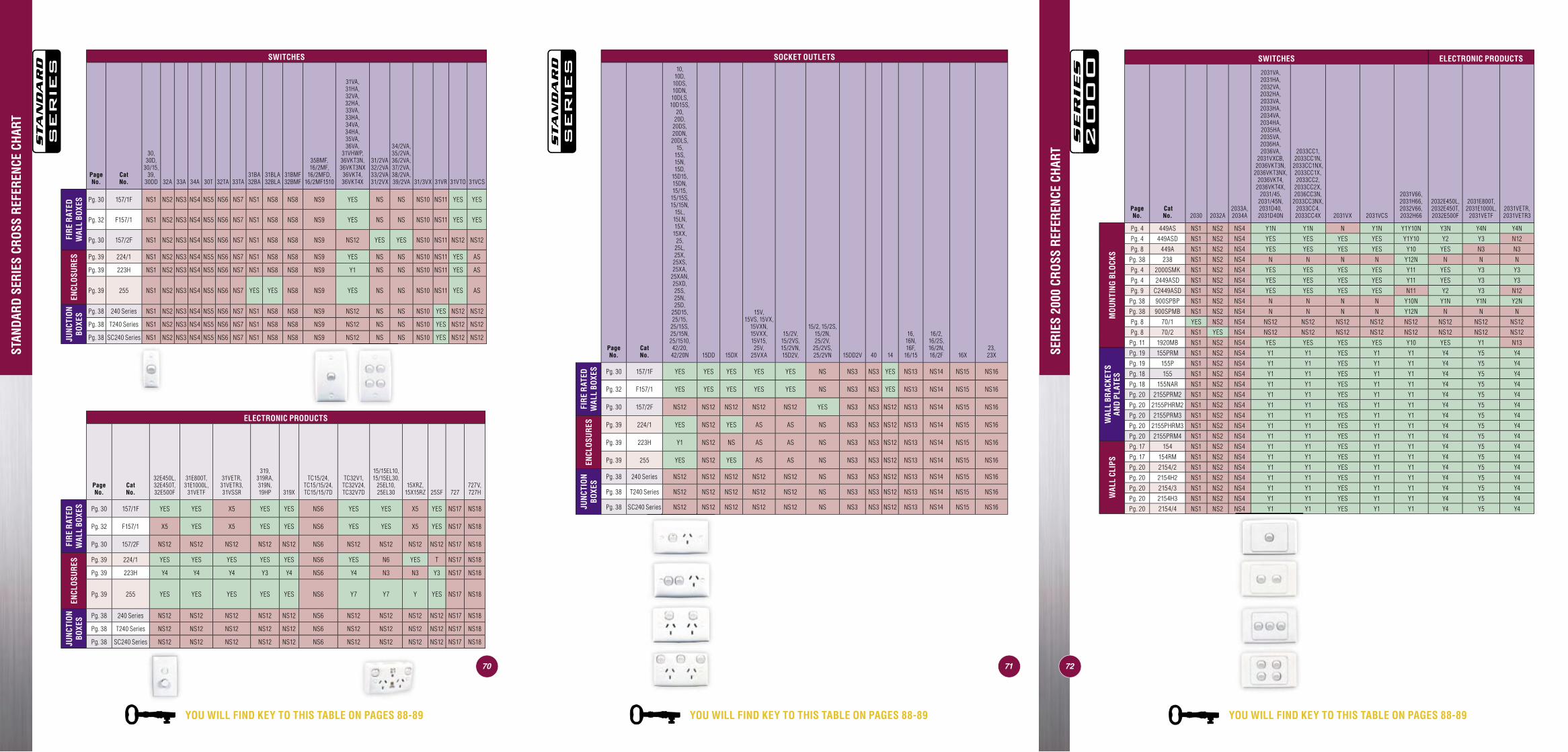
MOU
NTIN
G AC
CESS
ORIE
S QU
ICK
REFE
RENC
E GU
IDE
SWITCHES
Page No.
Cat No.
30, 30D,
30/15, 39,
30DD 32A 33A 34A 30T 32TA 33TA31BA 32BA
31BLA 32BLA
31BMF 32BMF
35BMF, 16/2MF,
16/2MFD, 16/2MF1510
31VA,31HA,32VA,32HA,33VA,33HA, 34VA,34HA, 35VA,36VA,
31VHWP, 36VKT3N, 36VKT3NX
36VKT4, 36VKT4X
31/2VA 32/2VA 33/2VA 31/2VX
34/2VA, 35/2VA, 36/2VA, 37/2VA, 38/2VA, 39/2VA 31/3VX 31VR 31VTO 31VCS
FIR
E R
ATED
W
ALL
BOXE
S Pg. 30 157/1F NS1 NS2 NS3 NS4 NS5 NS6 NS7 NS1 NS8 NS8 NS9 YES NS NS NS10 NS11 YES YES
Pg. 32 F157/1 NS1 NS2 NS3 NS4 NS5 NS6 NS7 NS1 NS8 NS8 NS9 YES NS NS NS10 NS11 YES YES
Pg. 30 157/2F NS1 NS2 NS3 NS4 NS5 NS6 NS7 NS1 NS8 NS8 NS9 NS12 YES YES NS10 NS11 NS12 NS12
ENCL
OSU
RES Pg. 39 224/1 NS1 NS2 NS3 NS4 NS5 NS6 NS7 NS1 NS8 NS8 NS9 YES NS NS NS10 NS11 YES AS
Pg. 39 223H NS1 NS2 NS3 NS4 NS5 NS6 NS7 NS1 NS8 NS8 NS9 Y1 NS NS NS10 NS11 YES AS
Pg. 39 255 NS1 NS2 NS3 NS4 NS5 NS6 NS7 YES YES NS8 NS9 YES NS NS NS10 NS11 YES AS
JUN
CTIO
N BO
XES Pg. 38 240 Series NS1 NS2 NS3 NS4 NS5 NS6 NS7 NS1 NS8 NS8 NS9 NS12 NS NS NS10 YES NS12 NS12
Pg. 38 T240 Series NS1 NS2 NS3 NS4 NS5 NS6 NS7 NS1 NS8 NS8 NS9 NS12 NS NS NS10 YES NS12 NS12
Pg. 38 SC240 Series NS1 NS2 NS3 NS4 NS5 NS6 NS7 NS1 NS8 NS8 NS9 NS12 NS NS NS10 YES NS12 NS12
ELECTRONIC PRODUCTS
Page No.
Cat No.
32E450L, 32E450T, 32E500F
31E800T, 31E1000L,
31VETF
31VETR, 31VETR3, 31VSSR
319, 319RA, 319N, 19HP 319X
TC15/24, TC15/15/24, TC15/15/7D
TC32V1, TC32V24, TC32V7D
15/15EL10, 15/15EL30,
25EL10,25EL30
15XRZ,15X15RZ 25SF 727
727V, 727H
FIR
E R
ATED
W
ALL
BOXE
S Pg. 30 157/1F YES YES X5 YES YES NS6 YES YES X5 YES NS17 NS18
Pg. 32 F157/1 X5 YES X5 YES YES NS6 YES YES X5 YES NS17 NS18
Pg. 30 157/2F NS12 NS12 NS12 NS12 NS12 NS6 NS12 NS12 NS12 NS12 NS17 NS18
ENCL
OSU
RES Pg. 39 224/1 YES YES YES YES YES NS6 YES N6 YES T NS17 NS18
Pg. 39 223H Y4 Y4 Y4 Y3 Y4 NS6 Y4 N3 N3 Y3 NS17 NS18
Pg. 39 255 YES YES YES YES YES NS6 Y7 Y7 Y YES NS17 NS18
JUN
CTIO
N BO
XES Pg. 38 240 Series NS12 NS12 NS12 NS12 NS12 NS6 NS12 NS12 NS12 NS12 NS17 NS18
Pg. 38 T240 Series NS12 NS12 NS12 NS12 NS12 NS6 NS12 NS12 NS12 NS12 NS17 NS18
Pg. 38 SC240 Series NS12 NS12 NS12 NS12 NS12 NS6 NS12 NS12 NS12 NS12 NS17 NS18
7170
SOCKET OUTLETS
Page No.
Cat No.
10,10D,
10DS,10DN, 10DLS,10D15S,
20, 20D,
20DS,20DN, 20DLS,
15,15S,15N, 15D,
15D15,15DN, 15/15,
15/15S, 15/15N,
15L,15LN,15X,
15XX,25,
25L,25X,
25XS, 25XA,
25XAN,25XD,25S, 25N,25D,
25D15, 25/15,
25/15S, 25/15N,25/1510, 42/20,42/20N 15DD 15DX
15V, 15VS, 15VX,
15VXN, 15VXX, 15V15,
25V, 25VXA
15/2V, 15/2VS, 15/2VN, 15D2V,
15/2, 15/2S, 15/2N, 25/2V,
25/2VS, 25/2VN 15DD2V 40 14
16, 16N, 16F,
16/15
16/2, 16/2S, 16/2N, 16/2F 16X
23, 23X
FIR
E R
ATED
W
ALL
BOXE
S Pg. 30 157/1F YES YES YES YES YES NS NS3 NS3 YES NS13 NS14 NS15 NS16
Pg. 32 F157/1 YES YES YES YES YES NS NS3 NS3 YES NS13 NS14 NS15 NS16
Pg. 30 157/2F NS12 NS12 NS12 NS12 NS12 YES NS3 NS3 NS12 NS13 NS14 NS15 NS16
ENCL
OSU
RES Pg. 39 224/1 YES NS12 YES AS AS NS NS3 NS3 NS12 NS13 NS14 NS15 NS16
Pg. 39 223H Y1 NS12 NS AS AS NS NS3 NS3 NS12 NS13 NS14 NS15 NS16
Pg. 39 255 YES NS12 YES AS AS NS NS3 NS3 NS12 NS13 NS14 NS15 NS16
JUN
CTIO
N BO
XES
Pg. 38 240 Series NS12 NS12 NS12 NS12 NS12 NS NS3 NS3 NS12 NS13 NS14 NS15 NS16
Pg. 38 T240 Series NS12 NS12 NS12 NS12 NS12 NS NS3 NS3 NS12 NS13 NS14 NS15 NS16
Pg. 38 SC240 Series NS12 NS12 NS12 NS12 NS12 NS NS3 NS3 NS12 NS13 NS14 NS15 NS16
SWITCHES ELECTRONIC PRODUCTS
Page No.
Cat No. 2030 2032A
2033A, 2034A
2031VA, 2031HA, 2032VA, 2032HA, 2033VA, 2033HA, 2034VA, 2034HA, 2035HA, 2035VA,2036HA, 2036VA,
2031VXCB, 2036VKT3N,
2036VKT3NX, 2036VKT4,
2036VKT4X, 2031/45,
2031/45N, 2031D40, 2031D40N
2033CC1, 2033CC1N,
2033CC1NX, 2033CC1X, 2033CC2,
2033CC2X, 2036CC3N,
2033CC3NX, 2033CC4, 2033CC4X 2031VX 2031VCS
2031V66, 2031H66, 2032V66, 2032H66
2032E450L, 2032E450T, 2032E500F
2031E800T, 2031E1000L,
2031VETF2031VETR, 2031VETR3
MO
UN
TIN
G BL
OCK
S
Pg. 4 449AS NS1 NS2 NS4 Y1N Y1N N Y1N Y1Y10N Y3N Y4N Y4N
Pg. 4 449ASD NS1 NS2 NS4 YES YES YES YES Y1Y10 Y2 Y3 N12
Pg. 8 449A NS1 NS2 NS4 YES YES YES YES Y10 YES N3 N3
Pg. 38 238 NS1 NS2 NS4 N N N N Y12N N N N
Pg. 4 2000SMK NS1 NS2 NS4 YES YES YES YES Y11 YES Y3 Y3
Pg. 4 2449ASD NS1 NS2 NS4 YES YES YES YES Y11 YES Y3 Y3
Pg. 9 C2449ASD NS1 NS2 NS4 YES YES YES YES N11 Y2 Y3 N12
Pg. 38 900SPBP NS1 NS2 NS4 N N N N Y10N Y1N Y1N Y2N
Pg. 38 900SPMB NS1 NS2 NS4 N N N N Y12N N N N
Pg. 8 70/1 YES NS2 NS4 NS12 NS12 NS12 NS12 NS12 NS12 NS12 NS12
Pg. 8 70/2 NS1 YES NS4 NS12 NS12 NS12 NS12 NS12 NS12 NS12 NS12
Pg. 11 1920MB NS1 NS2 NS4 YES YES YES YES Y10 YES Y1 N13
WAL
L BR
ACKE
TS
AND
PLAT
ES
Pg. 19 155PRM NS1 NS2 NS4 Y1 Y1 YES Y1 Y1 Y4 Y5 Y4
Pg. 19 155P NS1 NS2 NS4 Y1 Y1 YES Y1 Y1 Y4 Y5 Y4
Pg. 18 155 NS1 NS2 NS4 Y1 Y1 YES Y1 Y1 Y4 Y5 Y4
Pg. 18 155NAR NS1 NS2 NS4 Y1 Y1 YES Y1 Y1 Y4 Y5 Y4
Pg. 20 2155PRM2 NS1 NS2 NS4 Y1 Y1 YES Y1 Y1 Y4 Y5 Y4
Pg. 20 2155PHRM2 NS1 NS2 NS4 Y1 Y1 YES Y1 Y1 Y4 Y5 Y4
Pg. 20 2155PRM3 NS1 NS2 NS4 Y1 Y1 YES Y1 Y1 Y4 Y5 Y4
Pg. 20 2155PHRM3 NS1 NS2 NS4 Y1 Y1 YES Y1 Y1 Y4 Y5 Y4
Pg. 20 2155PRM4 NS1 NS2 NS4 Y1 Y1 YES Y1 Y1 Y4 Y5 Y4
WAL
L CL
IPS
Pg. 17 154 NS1 NS2 NS4 Y1 Y1 YES Y1 Y1 Y4 Y5 Y4
Pg. 17 154RM NS1 NS2 NS4 Y1 Y1 YES Y1 Y1 Y4 Y5 Y4
Pg. 20 2154/2 NS1 NS2 NS4 Y1 Y1 YES Y1 Y1 Y4 Y5 Y4
Pg. 20 2154H2 NS1 NS2 NS4 Y1 Y1 YES Y1 Y1 Y4 Y5 Y4
Pg. 20 2154/3 NS1 NS2 NS4 Y1 Y1 YES Y1 Y1 Y4 Y5 Y4
Pg. 20 2154H3 NS1 NS2 NS4 Y1 Y1 YES Y1 Y1 Y4 Y5 Y4
Pg. 20 2154/4 NS1 NS2 NS4 Y1 Y1 YES Y1 Y1 Y4 Y5 Y4
STAN
DARD
SER
IES
CROS
S RE
FERE
NCE
CHAR
T
SERI
ES 2
000
CROS
S RE
FERE
NCE
CHAR
T
72
YOU WILL FIND KEY TO THIS TABLE ON PAGES 88-89YOU WILL FIND KEY TO THIS TABLE ON PAGES 88-89 YOU WILL FIND KEY TO THIS TABLE ON PAGES 88-89
65
WAFER HEAD SCREWS - SELF DRILLING - IN BUCKETS
Cat. No. Description Length Width Depth Mounting Centres
Page No.
357WF22B Wafer Head Screw, 10 x 22mm (Cat. No. 357WF22)- bucket of 500. 22mm N/A N/A N/A 45
357WF30B Wafer Head Screw, 10 x 30mm (Cat. No. 357WF30)- bucket of 500. 30mm N/A N/A N/A 45
357WF40B Wafer Head Screw, 10 x 40mm (Cat. No. 357WF40)- bucket of 500. 40mm N/A N/A N/A 45
357WH12B Washer Head Screw, 8 x 12mm (Cat. No. 357WH12) - bucket of 1000. 12mm N/A N/A N/A 46
357WH25B Washer Head Screw, 8 x 25mm (Cat. No. 357WH25) - bucket of 500. 25mm N/A N/A N/A 46
357WHP32B Washer Head Screw, 8 x 32mm, needle point twinstart (357WHP32) - bucket of 500. 32mm N/A N/A N/A 46
MISCELLANEOUS SCREWS, NUTS & WALL PLUGS
31J Flat Head Screw - for fi xing 30 Series mechanisms. N/A N/A N/A N/A 46353 Raised Countersunk Head Screw, 12mm long. 12mm N/A N/A N/A 46353B Raised Countersunk Head Screw, 16mm long. 16mm N/A N/A N/A 46
355 Pan Head Screw, combined slot and Phillips recess, M3.5 X 0.8mm pitch, 32mm long. 32mm N/A N/A N/A 46
355A Pan Head Screw, combined slot and Phillips recess, M3.5 X 0.8mm pitch, 50mm long. 50mm N/A N/A N/A 46
355B Raised Countersunk Screw, M3.5 X 0.8mm pitch, 75mm long. 75mm N/A N/A N/A 46
B25-FSCountersunk Screw for BSL Metal Plate, M3.5 X 0.8mm pitch, 50mm long.
50mm N/A N/A N/A 46
BSL25-FSCountersunk Screw for BSL Metal Plate, M3.5 X 0.8mm pitch, 75mm long.
75mm N/A N/A N/A 46
356D Countersunk Head Screw, self tapping, electroplated- 16mm x No.4 gge. 16mm N/A N/A N/A 46
356E Cheese Head Screw, self tapping, electroplated- 20mm x No.6 gge. 20mm N/A N/A N/A 46
356F Countersunk Head Wood Screw, electroplated- 32mm x No.6 gge. 32mm N/A N/A N/A 46
358Wall Plug, with built-in screw nail - designed tomount accessories with 4.7mm mounting holes to awide range of materials.
N/A N/A N/A N/A 46
358LH Wall Plug, with built-in screw nail (suits battenholders and ceiling roses). N/A N/A N/A N/A 46
359 Square Nut, 6mm x 6mm, fi ts M3.5 x 0.8mmpitch screws. 6mm N/A N/A N/A 46
9 Number 9 Cap, suits switch plate screw recess. N/A N/A N/A N/A 46
POWER DRIVE BITS
357PB Power Drive Bit, No. 2 phillips head, single ended- 100mm long. 100mm N/A N/A N/A 47
357PB2 Power Drive Bit, No.2 phillips head, double ended- 100mm long. 100mm N/A N/A N/A 47
357PB150 Power Drive Bit, No.2 phillips head, single ended- 150mm long. 150mm N/A N/A N/A 47
357PBU Power Drive Bit, No.2 phillips head & 6mm fl at blade- 100mm long. 100mm N/A N/A N/A 47
357NS Power Drive Bit, 5/16” Nutsetter - 70mm long. 70mm N/A N/A N/A 47
CLIPSAL ‘BITSABOX’ AND ECONOMY VALUE PACK
357RP Clipsal Bitsabox - contains a variety of cableconnection and fast fi xing accessories. 430mm 290mm 192mm N/A 48
357RPBOX Clipsal Bitsabox (box only). 430mm 290mm 192mm N/A 48
357TB Economy Value Pack - contains a variety of screws. 310mm 200mm 47mm N/A 48/49
MOUNTING ACCESSORIES QUICK REFERENCE GUIDE
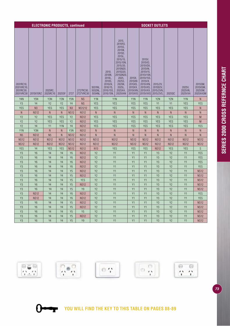
YOU WILL FIND THE KEY TO THIS TABLE ON PAGES 88-89
73
ELECTRONIC PRODUCTS, continued SOCKET OUTLETS
2031RC10, 2031VRC10, 2031RC30, 2031VRC30 2015X15RZ
2025RC, 2025RC10 2025SF 2727
2727RC30, 2727VRC30
5031NL, 5032NL, 5034NL
2010, 2010N, 2010L, 2010S,
2010LN, 2010/15,
2010/15S, 2010/15N,
2015, 2015FO, 2015S, 2015N, 2015D, 2015L,
2015/15, 2015/15N, 2015/20, 2015N20, 2015D20,
2015DN20, 2025,
2025S, 2025N, 2025L,
2025XA, 2025XAN
2015X, 2015XN 2015XS, 2015XX,
2015XXN, 2015XXS
2015V, 2015VD,
2015VDX, 2015VN, 2015V15,
2015V15N, 2015V15S, 2015VX,
2015VXN, 2015VXS, 2015VXX, 2015VXXS
2015/2V, 2015D2V, 2015/2VN, 2015/2VS, 2025QC
2025V, 2025VN, 2025VXA
2015SM, 2015XSM, 2025SM,
2025XASM
Y4N Y5N Y3N Y3N Y5N NS Y1N Y1N Y1N Y1N Y2N Y2N Y1N N
Y3 Y4 Y2 Y2 Y4 NS YES YES YES YES Y1 Y1 YES YES
YES N3 YES YES N3 NS1212 YES YES YES YES YES YES YES N
N NS12 N N NS12 NS12 N N N N N N N N
Y2 Y2 YES YES Y2 NS12 YES YES YES YES YES YES YES M
Y2 Y2 YES YES Y2 NS12 YES YES YES YES YES YES YES M
Y2 Y4 Y1 Y1N Y4 NS12 YES YES YES YES YES YES YES YES
Y1N Y3N N N Y3N NS12 N N N N N N N N
N5 NS12 N5 N NS12 NS12 N N N N N N N N
NS12 NS12 NS12 NS12 NS12 NS12 NS12 NS12 NS12 NS12 NS12 NS12 NS12 NS12
NS12 NS12 NS12 NS12 NS12 NS12 NS12 NS12 NS12 NS12 NS12 NS12 NS12 NS12
YES Y4 YES YES NS12 NS12 N13 YES YES YES NS12 YES YES S
Y3 Y6 Y4 Y4 Y6 NS12 Y2 Y1 Y1 Y1 Y3 Y2 Y1 YES
Y3 Y6 Y4 Y4 Y6 NS12 Y2 Y1 Y1 Y1 Y3 Y2 Y1 YES
Y3 Y6 Y4 Y4 Y6 NS12 Y2 Y1 Y1 Y1 Y3 Y2 Y1 YES
Y3 Y6 Y4 Y4 Y6 NS12 Y2 Y1 Y1 Y1 Y3 Y2 Y1 YES
Y3 Y6 Y4 Y4 Y5 NS12 Y2 Y1 Y1 Y1 Y3 Y2 Y1 NS12
Y3 Y6 Y4 Y4 Y5 NS12 Y2 Y1 Y1 Y1 Y3 Y2 Y1 NS12
Y3 Y6 Y4 Y4 Y5 YES Y2 Y1 Y1 Y1 Y3 Y2 Y1 NS12
Y3 Y6 Y4 Y4 Y5 NS12 Y2 Y1 Y1 Y1 Y3 Y2 Y1 NS12
Y3 Y6 Y4 Y4 Y5 Y9 Y2 Y1 Y1 Y1 Y3 Y2 Y1 NS12
Y3 NS12 Y4 Y4 Y6 NS12 Y2 Y1 Y1 Y1 Y3 Y2 Y1 YES
Y3 NS12 Y4 Y4 Y6 NS12 Y2 Y1 Y1 Y1 Y3 Y2 Y1 YES
Y3 Y6 Y4 Y4 Y5 NS12 Y2 Y1 Y1 Y1 Y3 Y2 Y1 NS12
Y3 Y6 Y4 Y4 Y5 NS12 Y2 Y1 Y1 Y1 Y3 Y2 Y1 NS12
Y3 Y6 Y4 Y4 Y5 Y5 Y2 Y1 Y1 Y1 Y3 Y2 Y1 NS12
Y3 Y6 Y4 Y4 Y5 NS12 Y2 Y1 Y1 Y1 Y3 Y2 Y1 NS12
Y3 Y6 Y4 Y4 Y5 Y9 Y2 Y1 Y1 Y1 Y3 Y2 Y1 NS12SE
RIES
200
0 CR
OSS
REFE
RNCE
CHA
RT
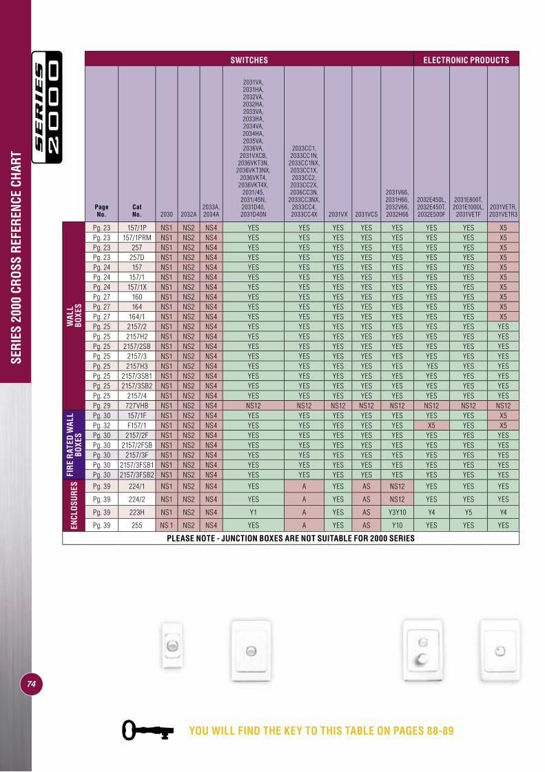
74
SWITCHES ELECTRONIC PRODUCTS
Page No.
Cat No. 2030 2032A
2033A, 2034A
2031VA, 2031HA, 2032VA, 2032HA, 2033VA, 2033HA, 2034VA, 2034HA, 2035VA, 2036VA,
2031VXCB, 2036VKT3N,
2036VKT3NX, 2036VKT4,
2036VKT4X, 2031/45,
2031/45N, 2031D40, 2031D40N
2033CC1, 2033CC1N,
2033CC1NX, 2033CC1X, 2033CC2,
2033CC2X, 2036CC3N,
2033CC3NX, 2033CC4, 2033CC4X 2031VX 2031VCS
2031V66, 2031H66, 2032V66, 2032H66
2032E450L, 2032E450T, 2032E500F
2031E800T, 2031E1000L,
2031VETF2031VETR, 2031VETR3
WAL
L B
OXES
Pg. 23 157/1P NS1 NS2 NS4 YES YES YES YES YES YES YES X5Pg. 23 157/1PRM NS1 NS2 NS4 YES YES YES YES YES YES YES X5Pg. 23 257 NS1 NS2 NS4 YES YES YES YES YES YES YES X5Pg. 23 257D NS1 NS2 NS4 YES YES YES YES YES YES YES X5Pg. 24 157 NS1 NS2 NS4 YES YES YES YES YES YES YES X5Pg. 24 157/1 NS1 NS2 NS4 YES YES YES YES YES YES YES X5Pg. 24 157/1X NS1 NS2 NS4 YES YES YES YES YES YES YES X5Pg. 27 160 NS1 NS2 NS4 YES YES YES YES YES YES YES X5Pg. 27 164 NS1 NS2 NS4 YES YES YES YES YES YES YES X5Pg. 27 164/1 NS1 NS2 NS4 YES YES YES YES YES YES YES X5Pg. 25 2157/2 NS1 NS2 NS4 YES YES YES YES YES YES YES YESPg. 25 2157H2 NS1 NS2 NS4 YES YES YES YES YES YES YES YESPg. 25 2157/2SB NS1 NS2 NS4 YES YES YES YES YES YES YES YESPg. 25 2157/3 NS1 NS2 NS4 YES YES YES YES YES YES YES YESPg. 25 2157H3 NS1 NS2 NS4 YES YES YES YES YES YES YES YESPg. 25 2157/3SB1 NS1 NS2 NS4 YES YES YES YES YES YES YES YESPg. 25 2157/3SB2 NS1 NS2 NS4 YES YES YES YES YES YES YES YESPg. 25 2157/4 NS1 NS2 NS4 YES YES YES YES YES YES YES YESPg. 29 727VHB NS1 NS2 NS4 NS12 NS12 NS12 NS12 NS12 NS12 NS12 NS12
FIR
E R
ATED
WAL
L BO
XES
Pg. 30 157/1F NS1 NS2 NS4 YES YES YES YES YES YES YES X5Pg. 32 F157/1 NS1 NS2 NS4 YES YES YES YES YES X5 YES X5Pg. 30 2157/2F NS1 NS2 NS4 YES YES YES YES YES YES YES YESPg. 30 2157/2FSB NS1 NS2 NS4 YES YES YES YES YES YES YES YESPg. 30 2157/3F NS1 NS2 NS4 YES YES YES YES YES YES YES YESPg. 30 2157/3FSB1 NS1 NS2 NS4 YES YES YES YES YES YES YES YESPg. 30 2157/3FSB2 NS1 NS2 NS4 YES YES YES YES YES YES YES YES
ENCL
OSU
RES Pg. 39 224/1 NS1 NS2 NS4 YES A YES AS NS12 YES YES YES
Pg. 39 224/2 NS1 NS2 NS4 YES A YES AS NS12 YES YES YES
Pg. 39 223H NS1 NS2 NS4 Y1 A YES AS Y3Y10 Y4 Y5 Y4
Pg. 39 255 NS 1 NS2 NS4 YES A YES AS Y10 YES YES YES
PLEASE NOTE - JUNCTION BOXES ARE NOT SUITABLE FOR 2000 SERIES
SERI
ES 2
000
CROS
S RE
FERE
NCE
CHAR
T
YOU WILL FIND THE KEY TO THIS TABLE ON PAGES 88-89
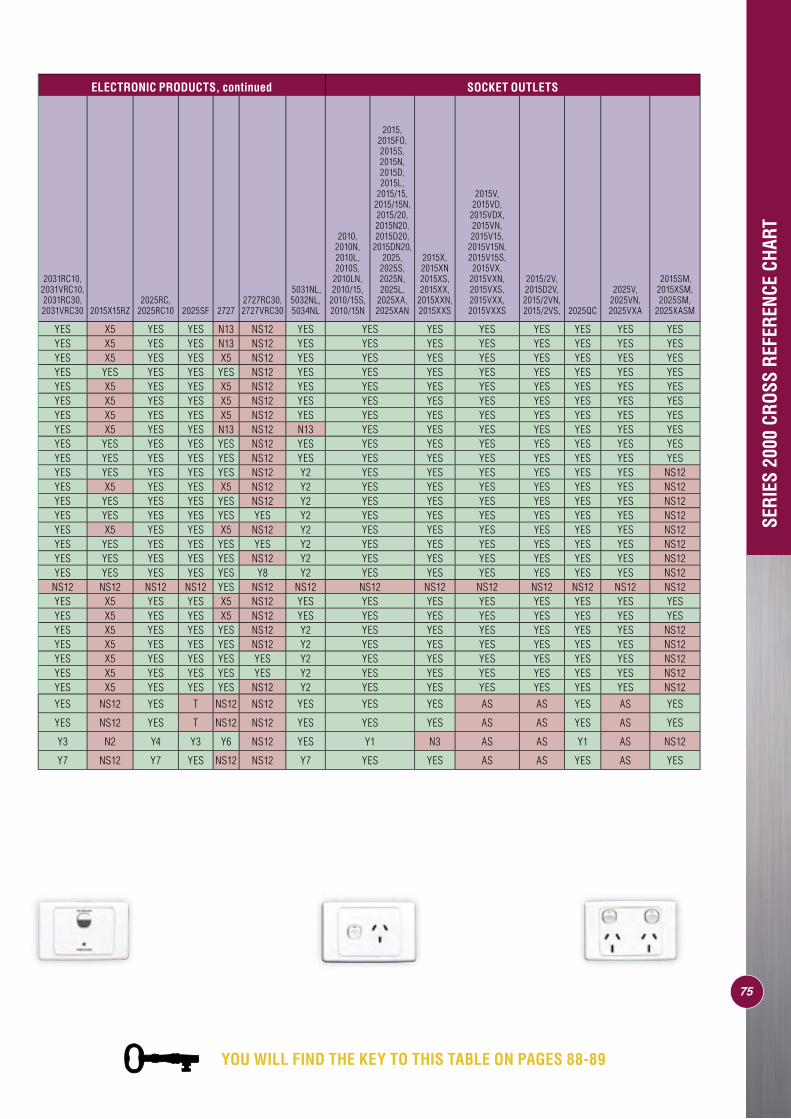
75
ELECTRONIC PRODUCTS, continued SOCKET OUTLETS
2031RC10, 2031VRC10, 2031RC30, 2031VRC30 2015X15RZ
2025RC, 2025RC10 2025SF 2727
2727RC30, 2727VRC30
5031NL, 5032NL, 5034NL
2010, 2010N, 2010L, 2010S,
2010LN, 2010/15,
2010/15S, 2010/15N
2015, 2015FO, 2015S, 2015N, 2015D, 2015L,
2015/15, 2015/15N, 2015/20, 2015N20, 2015D20,
2015DN20, 2025,
2025S, 2025N, 2025L,
2025XA, 2025XAN
2015X, 2015XN 2015XS, 2015XX,
2015XXN, 2015XXS
2015V, 2015VD,
2015VDX, 2015VN, 2015V15,
2015V15N, 2015V15S, 2015VX,
2015VXN, 2015VXS, 2015VXX, 2015VXXS
2015/2V, 2015D2V, 2015/2VN, 2015/2VS, 2025QC
2025V, 2025VN, 2025VXA
2015SM, 2015XSM, 2025SM,
2025XASM
YES X5 YES YES N13 NS12 YES YES YES YES YES YES YES YESYES X5 YES YES N13 NS12 YES YES YES YES YES YES YES YESYES X5 YES YES X5 NS12 YES YES YES YES YES YES YES YESYES YES YES YES YES NS12 YES YES YES YES YES YES YES YESYES X5 YES YES X5 NS12 YES YES YES YES YES YES YES YESYES X5 YES YES X5 NS12 YES YES YES YES YES YES YES YESYES X5 YES YES X5 NS12 YES YES YES YES YES YES YES YESYES X5 YES YES N13 NS12 N13 YES YES YES YES YES YES YESYES YES YES YES YES NS12 YES YES YES YES YES YES YES YESYES YES YES YES YES NS12 YES YES YES YES YES YES YES YESYES YES YES YES YES NS12 Y2 YES YES YES YES YES YES NS12YES X5 YES YES X5 NS12 Y2 YES YES YES YES YES YES NS12YES YES YES YES YES NS12 Y2 YES YES YES YES YES YES NS12YES YES YES YES YES YES Y2 YES YES YES YES YES YES NS12YES X5 YES YES X5 NS12 Y2 YES YES YES YES YES YES NS12YES YES YES YES YES YES Y2 YES YES YES YES YES YES NS12YES YES YES YES YES NS12 Y2 YES YES YES YES YES YES NS12YES YES YES YES YES Y8 Y2 YES YES YES YES YES YES NS12
NS12 NS12 NS12 NS12 YES NS12 NS12 NS12 NS12 NS12 NS12 NS12 NS12 NS12YES X5 YES YES X5 NS12 YES YES YES YES YES YES YES YESYES X5 YES YES X5 NS12 YES YES YES YES YES YES YES YESYES X5 YES YES YES NS12 Y2 YES YES YES YES YES YES NS12YES X5 YES YES YES NS12 Y2 YES YES YES YES YES YES NS12YES X5 YES YES YES YES Y2 YES YES YES YES YES YES NS12YES X5 YES YES YES YES Y2 YES YES YES YES YES YES NS12YES X5 YES YES YES NS12 Y2 YES YES YES YES YES YES NS12
YES NS12 YES T NS12 NS12 YES YES YES AS AS YES AS YES
YES NS12 YES T NS12 NS12 YES YES YES AS AS YES AS YES
Y3 N2 Y4 Y3 Y6 NS12 YES Y1 N3 AS AS Y1 AS NS12
Y7 NS12 Y7 YES NS12 NS12 Y7 YES YES AS AS YES AS YESSE
RIES
200
0 CR
OSS
REFE
RENC
E CH
ART
YOU WILL FIND THE KEY TO THIS TABLE ON PAGES 88-89
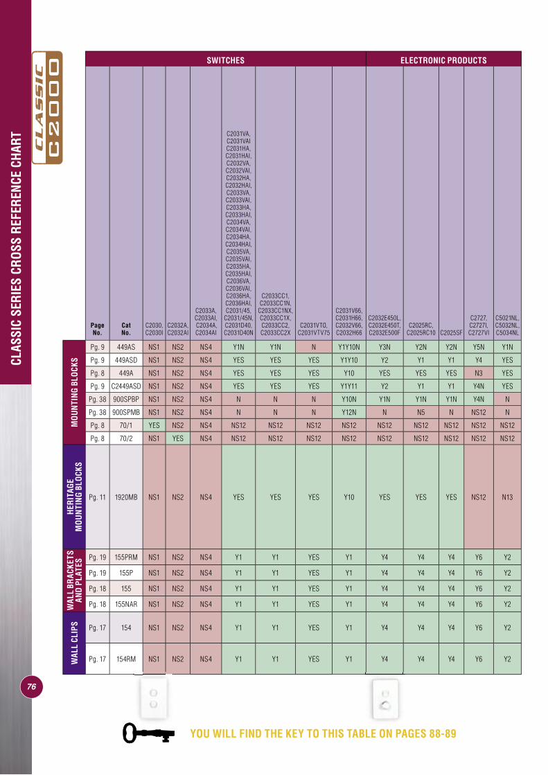
CLAS
SIC
SERI
ES C
ROSS
REF
EREN
CE C
HART
76
SWITCHES ELECTRONIC PRODUCTS
Page No.
Cat No.
C2030, C2030I
C2032A, C2032AI
C2033A,C2033AI, C2034A,C2034AI
C2031VA, C2031VAI C2031HA, C2031HAI, C2032VA, C2032VAI, C2032HA, C2032HAI, C2033VA, C2033VAI, C2033HA, C2033HAI, C2034VA, C2034VAI, C2034HA, C2034HAI, C2035VA, C2035VAI, C2035HA, C2035HAI, C2036VA, C2036VAI, C2036HA, C2036HAI, C2031/45,
C2031/45N, C2031D40, C2031D40N
C2033CC1, C2033CC1N,
C2033CC1NX, C2033CC1X, C2033CC2, C2033CC2X
C2031VTO, C2031VTV75
C2031V66, C2031H66, C2032V66, C2032H66
C2032E450L, C2032E450T, C2032E500F
C2025RC, C2025RC10 C2025SF
C2727, C2727I, C2727VI
C5021NL, C5032NL, C5034NL
MO
UN
TIN
G BL
OCK
S
Pg. 9 449AS NS1 NS2 NS4 Y1N Y1N N Y1Y10N Y3N Y2N Y2N Y5N Y1N
Pg. 9 449ASD NS1 NS2 NS4 YES YES YES Y1Y10 Y2 Y1 Y1 Y4 YES
Pg. 8 449A NS1 NS2 NS4 YES YES YES Y10 YES YES YES N3 YES
Pg. 9 C2449ASD NS1 NS2 NS4 YES YES YES Y1Y11 Y2 Y1 Y1 Y4N YES
Pg. 38 900SPBP NS1 NS2 NS4 N N N Y10N Y1N Y1N Y1N Y4N N
Pg. 38 900SPMB NS1 NS2 NS4 N N N Y12N N N5 N NS12 N
Pg. 8 70/1 YES NS2 NS4 NS12 NS12 NS12 NS12 NS12 NS12 NS12 NS12 NS12
Pg. 8 70/2 NS1 YES NS4 NS12 NS12 NS12 NS12 NS12 NS12 NS12 NS12 NS12
HER
ITAG
E M
OU
NTI
NG
BLO
CKS
Pg. 11 1920MB NS1 NS2 NS4 YES YES YES Y10 YES YES YES NS12 N13
WAL
L BR
ACKE
TS
AND
PLAT
ES
Pg. 19 155PRM NS1 NS2 NS4 Y1 Y1 YES Y1 Y4 Y4 Y4 Y6 Y2
Pg. 19 155P NS1 NS2 NS4 Y1 Y1 YES Y1 Y4 Y4 Y4 Y6 Y2
Pg. 18 155 NS1 NS2 NS4 Y1 Y1 YES Y1 Y4 Y4 Y4 Y6 Y2
Pg. 18 155NAR NS1 NS2 NS4 Y1 Y1 YES Y1 Y4 Y4 Y4 Y6 Y2
WAL
L CL
IPS Pg. 17 154 NS1 NS2 NS4 Y1 Y1 YES Y1 Y4 Y4 Y4 Y6 Y2
Pg. 17 154RM NS1 NS2 NS4 Y1 Y1 YES Y1 Y4 Y4 Y4 Y6 Y2
YOU WILL FIND THE KEY TO THIS TABLE ON PAGES 88-89
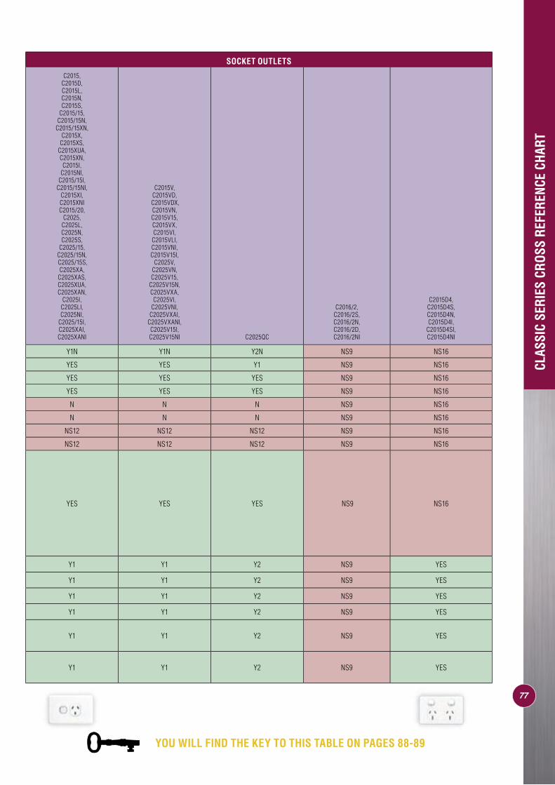
CLAS
SIC
SERI
ES C
ROSS
REF
EREN
CE C
HART
SOCKET OUTLETS
C2015, C2015D, C2015L, C2015N, C2015S,
C2015/15, C2015/15N,
C2015/15XN, C2015X,
C2015XS, C2015XUA, C2015XN, C2015I,
C2015NI, C2015/15I,
C2015/15NI, C2015XI, C2015XNIC2015/20,
C2025, C2025L, C2025N, C2025S,
C2025/15, C2025/15N, C2025/15S, C2025XA,
C2025XAS, C2025XUA, C2025XAN,
C2025I, C2025LI, C2025NI,
C2025/15I, C2025XAI, C2025XANI
C2015V, C2015VD,
C2015VDX, C2015VN, C2015V15, C2015VX, C2015VI,
C2015VLI, C2015VNI, C2015V15I,
C2025V, C2025VN, C2025V15,
C2025V15N, C2025VXA, C2025VI,
C2025VNI, C2025VXAI,
C2025VXANI, C2025V15I, C2025V15NI C2025QC
C2016/2, C2016/2S, C2016/2N, C2016/2D, C2016/2NI
C2015D4, C2015D4S, C2015D4N, C2015D4I,
C2015D4SI, C2015D4NI
Y1N Y1N Y2N NS9 NS16
YES YES Y1 NS9 NS16
YES YES YES NS9 NS16
YES YES YES NS9 NS16
N N N NS9 NS16
N N N NS9 NS16
NS12 NS12 NS12 NS9 NS16
NS12 NS12 NS12 NS9 NS16
YES YES YES NS9 NS16
Y1 Y1 Y2 NS9 YES
Y1 Y1 Y2 NS9 YES
Y1 Y1 Y2 NS9 YES
Y1 Y1 Y2 NS9 YES
Y1 Y1 Y2 NS9 YES
Y1 Y1 Y2 NS9 YES
77
YOU WILL FIND THE KEY TO THIS TABLE ON PAGES 88-89
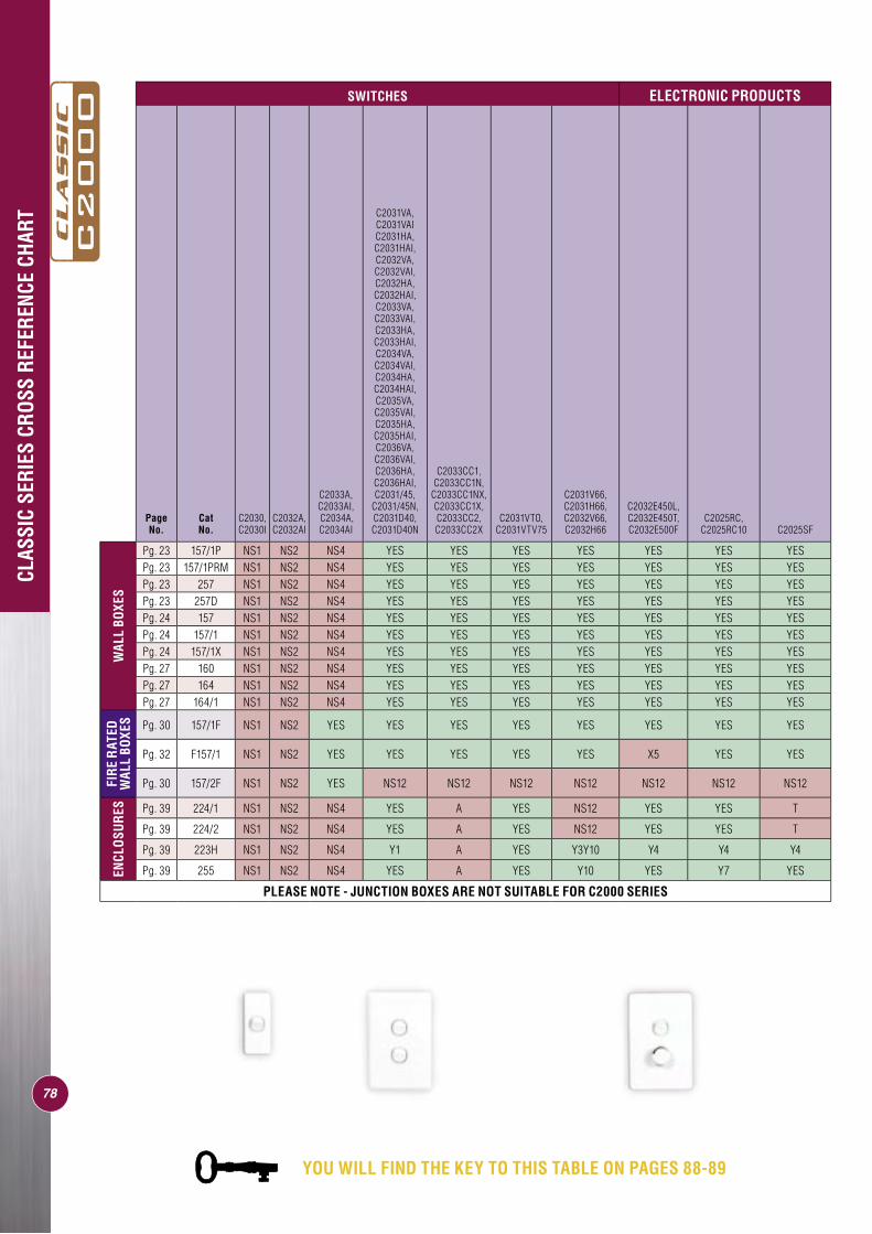
78
SWITCHES ELECTRONIC PRODUCTS
Page No.
Cat No.
C2030, C2030I
C2032A, C2032AI
C2033A,C2033AI, C2034A,C2034AI
C2031VA, C2031VAI C2031HA, C2031HAI, C2032VA, C2032VAI, C2032HA, C2032HAI, C2033VA, C2033VAI, C2033HA, C2033HAI, C2034VA, C2034VAI, C2034HA, C2034HAI, C2035VA, C2035VAI, C2035HA, C2035HAI, C2036VA, C2036VAI, C2036HA, C2036HAI, C2031/45,
C2031/45N, C2031D40, C2031D40N
C2033CC1, C2033CC1N,
C2033CC1NX, C2033CC1X, C2033CC2, C2033CC2X
C2031VTO, C2031VTV75
C2031V66, C2031H66, C2032V66, C2032H66
C2032E450L, C2032E450T, C2032E500F
C2025RC, C2025RC10 C2025SF
WAL
L BO
XES
Pg. 23 157/1P NS1 NS2 NS4 YES YES YES YES YES YES YESPg. 23 157/1PRM NS1 NS2 NS4 YES YES YES YES YES YES YESPg. 23 257 NS1 NS2 NS4 YES YES YES YES YES YES YESPg. 23 257D NS1 NS2 NS4 YES YES YES YES YES YES YESPg. 24 157 NS1 NS2 NS4 YES YES YES YES YES YES YESPg. 24 157/1 NS1 NS2 NS4 YES YES YES YES YES YES YESPg. 24 157/1X NS1 NS2 NS4 YES YES YES YES YES YES YESPg. 27 160 NS1 NS2 NS4 YES YES YES YES YES YES YESPg. 27 164 NS1 NS2 NS4 YES YES YES YES YES YES YESPg. 27 164/1 NS1 NS2 NS4 YES YES YES YES YES YES YES
FIR
E R
ATED
W
ALL
BOXE
S Pg. 30 157/1F NS1 NS2 YES YES YES YES YES YES YES YES
Pg. 32 F157/1 NS1 NS2 YES YES YES YES YES X5 YES YES
Pg. 30 157/2F NS1 NS2 YES NS12 NS12 NS12 NS12 NS12 NS12 NS12
ENCL
OSU
RES Pg. 39 224/1 NS1 NS2 NS4 YES A YES NS12 YES YES T
Pg. 39 224/2 NS1 NS2 NS4 YES A YES NS12 YES YES T
Pg. 39 223H NS1 NS2 NS4 Y1 A YES Y3Y10 Y4 Y4 Y4
Pg. 39 255 NS1 NS2 NS4 YES A YES Y10 YES Y7 YES
PLEASE NOTE - JUNCTION BOXES ARE NOT SUITABLE FOR C2000 SERIES
CLAS
SIC
SERI
ES C
ROSS
REF
EREN
CE C
HART
YOU WILL FIND THE KEY TO THIS TABLE ON PAGES 88-89
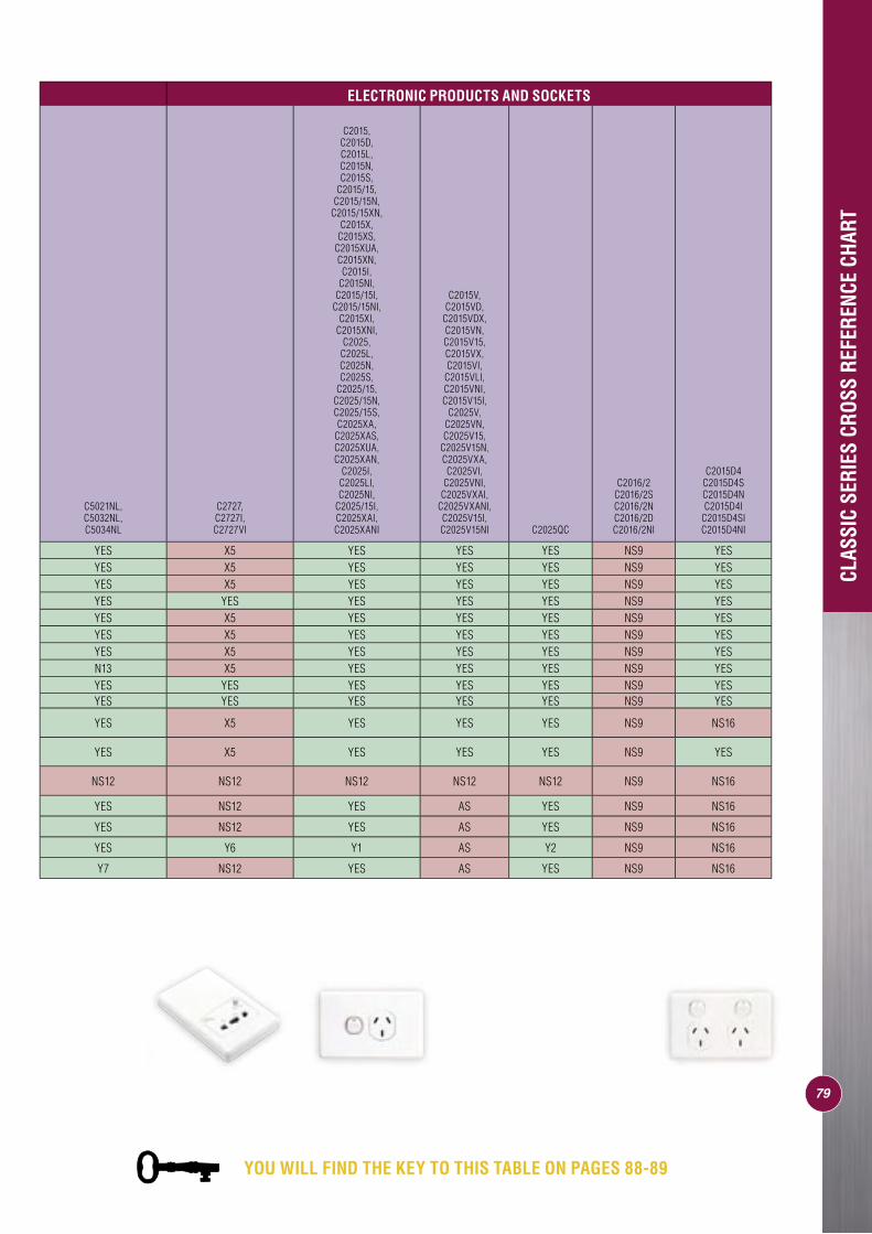
79
ELECTRONIC PRODUCTS AND SOCKETS
C5021NL, C5032NL, C5034NL
C2727, C2727I, C2727VI
C2015, C2015D, C2015L, C2015N, C2015S,
C2015/15, C2015/15N,
C2015/15XN, C2015X,
C2015XS, C2015XUA, C2015XN, C2015I,
C2015NI, C2015/15I,
C2015/15NI, C2015XI,
C2015XNI, C2025,
C2025L, C2025N, C2025S,
C2025/15, C2025/15N, C2025/15S, C2025XA,
C2025XAS, C2025XUA, C2025XAN,
C2025I, C2025LI, C2025NI,
C2025/15I, C2025XAI, C2025XANI
C2015V, C2015VD,
C2015VDX, C2015VN, C2015V15, C2015VX, C2015VI,
C2015VLI, C2015VNI, C2015V15I,
C2025V, C2025VN, C2025V15,
C2025V15N, C2025VXA, C2025VI,
C2025VNI, C2025VXAI,
C2025VXANI, C2025V15I, C2025V15NI C2025QC
C2016/2 C2016/2S C2016/2N C2016/2D C2016/2NI
C2015D4 C2015D4S C2015D4N C2015D4I
C2015D4SI C2015D4NI
YES X5 YES YES YES NS9 YESYES X5 YES YES YES NS9 YESYES X5 YES YES YES NS9 YESYES YES YES YES YES NS9 YESYES X5 YES YES YES NS9 YESYES X5 YES YES YES NS9 YESYES X5 YES YES YES NS9 YESN13 X5 YES YES YES NS9 YESYES YES YES YES YES NS9 YESYES YES YES YES YES NS9 YES
YES X5 YES YES YES NS9 NS16
YES X5 YES YES YES NS9 YES
NS12 NS12 NS12 NS12 NS12 NS9 NS16
YES NS12 YES AS YES NS9 NS16
YES NS12 YES AS YES NS9 NS16
YES Y6 Y1 AS Y2 NS9 NS16
Y7 NS12 YES AS YES NS9 NS16
CLAS
SIC
SERI
ES C
ROSS
REF
EREN
CE C
HART
YOU WILL FIND THE KEY TO THIS TABLE ON PAGES 88-89
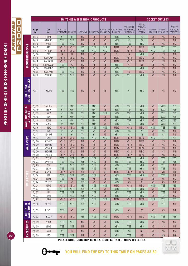
80
SWITCHES & ELECTRONIC PRODUCTS SOCKET OUTLETS
Page No.
Cat No.
P2031VA, P2031VA15 P2032VA P2031/2VA P2032/2VA
P2033/2VA P2034/2VA
P2031VTV75, P2031VTO
P2032E450L, P2032E450T, P2032E500F
P2015, P2015/15, P2015N, P2015V
P2015X, P2015XX
P2015/2, P2015/2/15
P2025/2, P2025/2N, P2025/2/15
MO
UN
TIN
G BL
OCK
S
Pg. 9 449AS Y1 Y1 NS NS NS YES Y3 Y2 NS NS NSPg. 9 449ASD YES YES NS NS NS YES Y2 Y2 NS NS NSPg. 8 449A YES YES NS NS NS YES YES YES NS NS NSPg. 8 448 NS12 NS12 YES YES YES NS12 NS12 NS12 YES YES YESPg. 9 448SD NS12 NS12 YES YES YES NS12 NS12 NS12 YES YES YES
Pg. 38 238 N N NS NS NS N N YES NS NS NSPg. 4 2000SMK NS12 NS12 NS NS NS NS12 NS12 NS12 NS NS NSPg. 4 2449ASD NS12 NS12 NS NS NS NS12 NS12 NS12 NS NS NSPg. 9 C2449ASD YES N7 NS NS NS YES N7 N1 NS NS NS
Pg. 38 900SPBP YES YES NS NS NS YES Y1 YES NS NS NSPg. 38 900SPMB YES YES NS NS NS YES N NS12 NS NS NSPg. 9 25ELSB YES YES NS NS NS YES YES YES NS NS NS
HER
ITAG
E M
OU
NTI
NG
BLO
CKS
Pg. 11 1920MB YES YES NS NS NS YES Y1 YES NS NS NS
WAL
L BR
ACKE
TS
& P
LATE
S
Pg. 19 155PRM Y1 Y1X1 Y1 Y1X1 NS YES Y5R YES NS Y2X1 YESPg. 19 155P Y1 Y1X1 Y1 Y1X1 NS YES Y5R YES NS Y2X1 YESPg. 19 155P2 Y1 Y1X1 Y1 Y1X1 YES YES Y5R YES NS YES YESPg. 18 155 Y1 Y1X1 Y1 Y1X1 NS YES Y5R YES NS Y2X1 YESPg. 18 155N Y1 Y1X1 Y1 Y1X1 NS YES Y5R YES NS Y2X1 YESPg. 18 155NAR Y1 Y1X1 Y1 Y1X1 NS YES Y5R YES NS Y2X1 YESPg. 19 156/2 NS12 NS12 YES YES YES NS12 NS12 NS12 YES YES YES
WAL
L CL
IPS
Pg. 17 154 Y1 Y1 Y1 Y1 NS YES Y3 Y3 NS Y3 NSPg. 17 154RM Y1 Y1 Y1 Y1 NS YES Y3 Y3 NS Y3 NSPg. 17 154/2 NS12 NS12 YES YES YES NS12 NS12 NS12 YES YES YESPg. 20 2154/2 NS12 NS12 NS NS NS NS12 NS12 NS12 NS NS NSPg. 20 2154H2 NS12 NS12 NS NS NS NS12 NS12 NS12 NS NS NSPg.20 2154/3 NS12 NS12 NS NS NS NS12 NS12 NS12 NS NS NSPg. 20 2154H3 NS12 NS12 NS NS NS NS12 NS12 NS12 NS NS NSPg. 20 2154/4 NS12 NS12 NS NS NS NS12 NS12 NS12 NS NS NS
WAL
L BO
XES
Pg. 23 157/1P YES YES YES YES NS YES YES YES NS YES YESPg. 23 157/1PRM YES YES YES YES NS YES YES YES NS YES YESPg. 23 257 YES YES YES YES NS YES YES YES NS YES NSPg. 23 257D YES YES YES YES NS YES YES YES NS YES NSPg. 23 257D2 NS12 NS12 VH VH VH NS12 NS12 NS12 VH VH VHPg. 24 157 YES YES YES YES NS YES YES YES NS YES NSPg. 24 157/1 YES X5 YES X5 NS YES X5 X5 NS X5 NSPg. 24 157/1X YES X5 YES X5 NS YES X5 X5 NS X5 NSPg. 24 157/2 NS12 NS12 YES YES YES NS12 NS12 NS12 YES YES YESPg. 27 160 YES YES YES YES NS YES YES YES NS YES NSPg. 27 164 YES YES YES YES NS YES YES YES NS YES NSPg. 27 164/1 YES YES YES YES NS YES YES YES NS YES NSPg. 27 164/2 NS12 NS12 YES YES YES NS12 NS12 NS12 YES YES YES
FIR
E R
ATED
W
ALL
BOXE
S Pg. 30 157/1F YES YES YES YES NS YES YES YES NS YES NS
Pg. 32 F157/1 YES X5 YES X5 NS YES X5 X5 NS X5 NS
Pg. 32 157/2F NS12 NS12 YES YES YES NS12 NS12 NS12 YES YES YES
ENCL
OSU
RES Pg. 39 224/1 YES YES NS NS NS YES YES YES NS NS NS
Pg. 39 224/2 YES YES NS NS NS YES YES YES NS NS NS
Pg. 39 223H Y1 N3 NS NS NS YES Y3 N3 NS NS NS
Pg. 39 255 YES YES NS NS NS YES YES N3 NS NS NS
PLEASE NOTE - JUNCTION BOXES ARE NOT SUITABLE FOR P2000 SERIES
PRES
TIGE
SER
IES
CROS
S RE
FERE
NCE
CHAR
T
NS NS
YOU WILL FIND THE KEY TO THIS TABLE ON PAGES 88-89
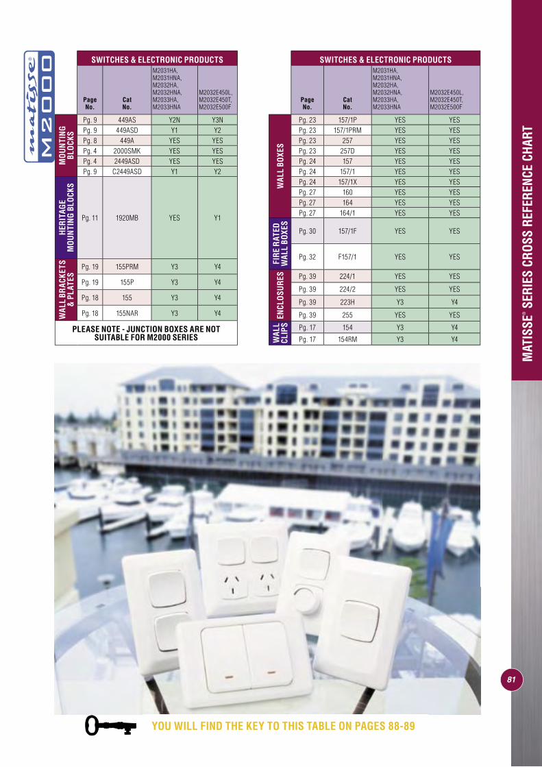
81
MAT
ISSE
SER
IES
CROS
S RE
FERE
NCE
CHAR
T
SWITCHES & ELECTRONIC PRODUCTS
Page No.
Cat No.
M2031HA, M2031HNA, M2032HA, M2032HNA, M2033HA, M2033HNA
M2032E450L, M2032E450T, M2032E500F
MO
UN
TIN
G BL
OCK
S
Pg. 9 449AS Y2N Y3NPg. 9 449ASD Y1 Y2Pg. 8 449A YES YESPg. 4 2000SMK YES YESPg. 4 2449ASD YES YESPg. 9 C2449ASD Y1 Y2
HER
ITAG
E M
OU
NTI
NG
BLO
CKS
Pg. 11 1920MB YES Y1
WAL
L BR
ACKE
TS
& P
LATE
S
Pg. 19 155PRM Y3 Y4
Pg. 19 155P Y3 Y4
Pg. 18 155 Y3 Y4
Pg. 18 155NAR Y3 Y4
PLEASE NOTE - JUNCTION BOXES ARE NOT SUITABLE FOR M2000 SERIES
SWITCHES & ELECTRONIC PRODUCTS
Page No.
Cat No.
M2031HA, M2031HNA, M2032HA, M2032HNA, M2033HA, M2033HNA
M2032E450L, M2032E450T, M2032E500F
WAL
L BO
XES
Pg. 23 157/1P YES YESPg. 23 157/1PRM YES YESPg. 23 257 YES YESPg. 23 257D YES YESPg. 24 157 YES YESPg. 24 157/1 YES YESPg. 24 157/1X YES YESPg. 27 160 YES YESPg. 27 164 YES YESPg. 27 164/1 YES YES
FIR
E R
ATED
W
ALL
BOXE
S
Pg. 30 157/1F YES YES
Pg. 32 F157/1 YES YES
ENCL
OSU
RES Pg. 39 224/1 YES YES
Pg. 39 224/2 YES YES
Pg. 39 223H Y3 Y4
Pg. 39 255 YES YES
WAL
L CL
IPS Pg. 17 154 Y3 Y4
Pg. 17 154RM Y3 Y4
YOU WILL FIND THE KEY TO THIS TABLE ON PAGES 88-89
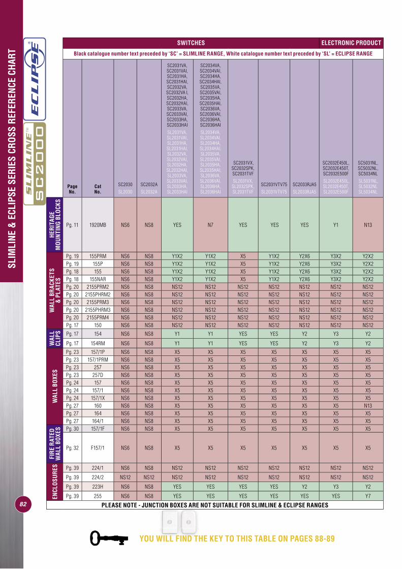
82
SLIM
LINE
& E
CLIP
SE S
ERIE
S CR
OSS
REFE
RENC
E CH
ART
SWITCHES ELECTRONIC PRODUCT
Black catalogue number text preceded by ‘SC’ = SLIMLINE RANGE, White catalogue number text preceded by ‘SL’ = ECLIPSE RANGE
Page No.
Cat No.
SC2030
SL2030
SC2032A
SL2032A
SC2031VA, SC2031VAI, SC2031HA, SC2031HAI, SC2032VA, SC2032VA I, SC2032HA, SC2032HAI, SC2033VA, SC2033VAI, SC2033HA, SC2033HAI
SL2031VA, SL2031VAI, SL2031HA, SL2031HAI, SL2032VA, SL2032VAI, SL2032HA, SL2032HAI, SL2033VA, SL2033VAI, SL2033HA, SL2033HAI
SC2034VA, SC2034VAI, SC2034HA, SC2034HAI, SC2035VA, SC2035VAI, SC2035HA, SC2035HAI, SC2036VA, SC2036VAI, SC2036HA, SC2036HAI
SL2034VA, SL2034VAI, SL2034HA, SL2034HAI, SL2035VA, SL2035VAI, SL2035HA, SL2035HAI, SL2036VA, SL2036VAI, SL2036HA, SL2036HAI
SC2031VX, SC2032SPK, SC2031TVF
SL2031VX, SL2032SPK, SL2031TVF
SC2031VTV75
SL2031VTV75
SC2033RJA5
SL2033RJA5
SC2032E450L, SC2032E450T, SC2032E500F
SL2032E450L, SL2032E450T, SL2032E500F
SC5031NL, SC5032NL, SC5034NL
SL5031NL, SL5032NL SL5034NL
HER
ITAG
E M
OU
NTI
NG
BLO
CKS
Pg. 11 1920MB NS6 NS8 YES N7 YES YES YES Y1 N13
WAL
L BR
ACKE
TS
& P
LATE
S
Pg. 19 155PRM NS6 NS8 Y1X2 Y1X2 X5 Y1X2 Y2X6 Y3X2 Y2X2Pg. 19 155P NS6 NS8 Y1X2 Y1X2 X5 Y1X2 Y2X6 Y3X2 Y2X2Pg. 18 155 NS6 NS8 Y1X2 Y1X2 X5 Y1X2 Y2X6 Y3X2 Y2X2Pg. 18 155NAR NS6 NS8 Y1X2 Y1X2 X5 Y1X2 Y2X6 Y3X2 Y2X2Pg. 20 2155PRM2 NS6 NS8 NS12 NS12 NS12 NS12 NS12 NS12 NS12Pg. 20 2155PHRM2 NS6 NS8 NS12 NS12 NS12 NS12 NS12 NS12 NS12Pg. 20 2155PRM3 NS6 NS8 NS12 NS12 NS12 NS12 NS12 NS12 NS12Pg. 20 2155PHRM3 NS6 NS8 NS12 NS12 NS12 NS12 NS12 NS12 NS12Pg. 20 2155PRM4 NS6 NS8 NS12 NS12 NS12 NS12 NS12 NS12 NS12Pg. 17 150 NS6 NS8 NS12 NS12 NS12 NS12 NS12 NS12 NS12
WAL
L CL
IPS Pg. 17 154 NS6 NS8 Y1 Y1 YES YES Y2 Y3 Y2
Pg. 17 154RM NS6 NS8 Y1 Y1 YES YES Y2 Y3 Y2
WAL
L BO
XES
Pg. 23 157/1P NS6 NS8 X5 X5 X5 X5 X5 X5 X5Pg. 23 157/1PRM NS6 NS8 X5 X5 X5 X5 X5 X5 X5Pg. 23 257 NS6 NS8 X5 X5 X5 X5 X5 X5 X5Pg. 23 257D NS6 NS8 X5 X5 X5 X5 X5 X5 X5Pg. 24 157 NS6 NS8 X5 X5 X5 X5 X5 X5 X5Pg. 24 157/1 NS6 NS8 X5 X5 X5 X5 X5 X5 X5Pg. 24 157/1X NS6 NS8 X5 X5 X5 X5 X5 X5 X5Pg. 27 160 NS6 NS8 X5 X5 X5 X5 X5 X5 N13Pg. 27 164 NS6 NS8 X5 X5 X5 X5 X5 X5 X5Pg. 27 164/1 NS6 NS8 X5 X5 X5 X5 X5 X5 X5
FIR
E R
ATED
W
ALL
BOXE
S Pg. 30 157/1F NS6 NS8 X5 X5 X5 X5 X5 X5 X5
Pg. 32 F157/1 NS6 NS8 X5 X5 X5 X5 X5 X5 X5
ENCL
OSU
RES Pg. 39 224/1 NS6 NS8 NS12 NS12 NS12 NS12 NS12 NS12 NS12
Pg. 39 224/2 NS12 NS12 NS12 NS12 NS12 NS12 NS12 NS12 NS12
Pg. 39 223H NS6 NS8 YES YES YES YES Y2 Y3 Y2
Pg. 39 255 NS6 NS8 YES YES YES YES YES YES Y7
PLEASE NOTE - JUNCTION BOXES ARE NOT SUITABLE FOR SLIMLINE & ECLIPSE RANGES
YOU WILL FIND THE KEY TO THIS TABLE ON PAGES 88-89
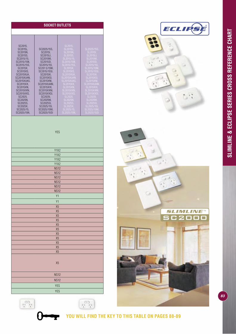
SLIM
LINE
& E
CLIP
SE S
ERIE
S CR
OSS
REFE
RENC
E CH
ART
SOCKET OUTLETS
SC2015, SC2015L, SC2015N, SC2015S,
SC2015/15, SC2015/15N, SC2015/15S,
SC2015X, SC2015XS,
SC2015XUA, SC2015XUAN, SC2015XUAS,
SC2015XX, SC2015XN,
SC2015XXN, SC2015XXS,
SC2025, SC2025N, SC2025S,SC2025X,
SC2025/15, SC2025/15N,
SC2025/15S,SC2015I,
SC2015LI, SC2015NI, SC2015SI,
SC2015/15I, SC201 5/15NI, SC2015/15SI,
SC2015XI, SC2015XSI, SC2015XNI,
SC2015XUANI, SC2015XXI,
SC2015XXNI, SC2015XXSI,
SC2025I, SC2025NI, SC2025SI,
SC2025/15I, SC2025/15NI, SC2025/15SI
SL2015, SL2015L, SL2015N, SL2015S,
SL2015/15, SL2015/15N, SL2015/15S,
SL2015X, SL2015XS,
SL2015XUA, SL2015XUAN, SL2015XUAS,
SL2015XX, SL2015XN,
SL2015XXN, SL2015XXS,
SL2025, SL2025N, SL2025S,SL2025X,
SL2025/15, SL2025/15N,
SL2025/15S, SL2015I,
SL2015LI, SL2015NI, SL2015SI,
SL2015/15I, SL2015/15NI, SL2015/15SI,
SL2015XI, SL2015XSI, SL2015XNI,
SL2015XUANI, SL2015XXI,
SL2015XXNI, SL2015XXSI,
SL2025I, SL2025NI, SL2025SI,
SL2025/15I, SL2025/15NI, SL2025/15SI
YES
Y1X2Y1X2Y1X2Y1X2NS12NS12NS12NS12NS12NS12
Y1
Y1
X5X5X5X5X5X5X5X5X5X5X5
X5
NS12
NS12
YES
YES83
YOU WILL FIND THE KEY TO THIS TABLE ON PAGES 88-89
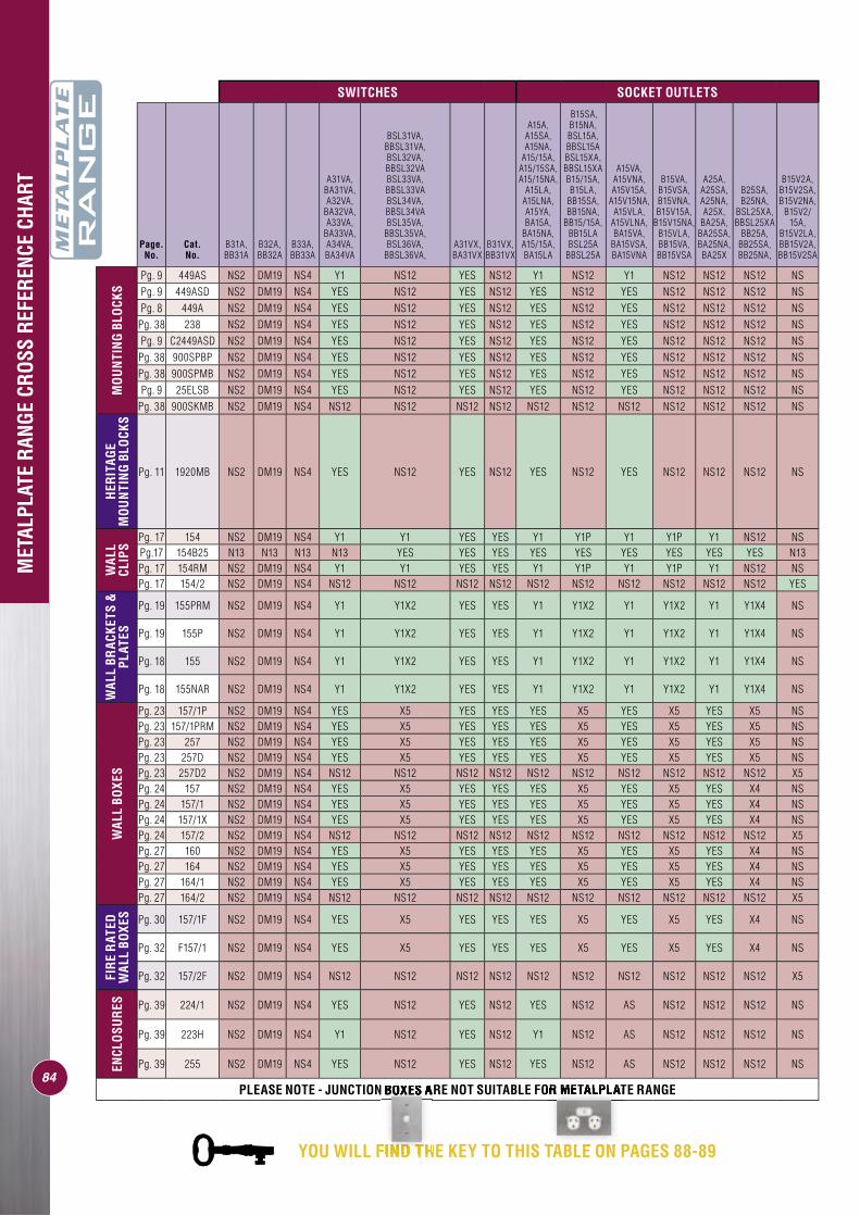
MET
ALPL
ATE
RANG
E CR
OSS
REFE
RENC
E CH
ART
SWITCHES SOCKET OUTLETS
Page. No.
Cat. No.
B31A, BB31A
B32A, BB32A
B33A, BB33A
A31VA, BA31VA, A32VA,
BA32VA, A33VA,
BA33VA, A34VA, BA34VA
BSL31VA, BBSL31VA,BSL32VA, BBSL32VABSL33VA, BBSL33VABSL34VA, BBSL34VABSL35VA,
BBSL35VA,BSL36VA,
BBSL36VA,A31VX, BA31VX
B31VX, BB31VX
A15A, A15SA, A15NA,
A15/15A, A15/15SA, A15/15NA,
A15LA, A15LNA, A15YA, BA15A,
BA15NA, A15/15A, BA15LA
B15SA, B15NA,BSL15A,BBSL15ABSL15XA,BBSL15XA B15/15A, B15LA,
BB15SA, BB15NA,
BB15/15A, BB15LABSL25A
BBSL25A
A15VA, A15VNA, A15V15A,
A15V15NA, A15VLA,
A15VLNA, BA15VA,
BA15VSA, BA15VNA
B15VA, B15VSA, B15VNA, B15V15A,
B15V15NA, B15VLA, BB15VA, BB15VSA
A25A, A25SA, A25NA, A25X,
BA25A, BA25SA, BA25NA, BA25X
B25SA, B25NA,
BSL25XA,BBSL25XA
BB25A, BB25SA, BB25NA,
B15V2A, B15V2SA, B15V2NA,
B15V2/15A,
B15V2LA, BB15V2A, BB15V2SA
MO
UN
TIN
G B
LOCK
S
Pg. 9 449AS NS2 DM19 NS4 Y1 NS12 YES NS12 Y1 NS12 Y1 NS12 NS12 NS12 NSPg. 9 449ASD NS2 DM19 NS4 YES NS12 YES NS12 YES NS12 YES NS12 NS12 NS12 NSPg. 8 449A NS2 DM19 NS4 YES NS12 YES NS12 YES NS12 YES NS12 NS12 NS12 NS
Pg. 38 238 NS2 DM19 NS4 YES NS12 YES NS12 YES NS12 YES NS12 NS12 NS12 NSPg. 9 C2449ASD NS2 DM19 NS4 YES NS12 YES NS12 YES NS12 YES NS12 NS12 NS12 NSPg. 38 900SPBP NS2 DM19 NS4 YES NS12 YES NS12 YES NS12 YES NS12 NS12 NS12 NSPg. 38 900SPMB NS2 DM19 NS4 YES NS12 YES NS12 YES NS12 YES NS12 NS12 NS12 NSPg. 9 25ELSB NS2 DM19 NS4 YES NS12 YES NS12 YES NS12 YES NS12 NS12 NS12 NS
Pg. 38 900SKMB NS2 DM19 NS4 NS12 NS12 NS12 NS12 NS12 NS12 NS12 NS12 NS12 NS12 NS
HER
ITAG
E M
OU
NTI
NG
BLO
CKS
Pg. 11 1920MB NS2 DM19 NS4 YES NS12 YES NS12 YES NS12 YES NS12 NS12 NS12 NS
WAL
L CL
IPS
Pg. 17 154 NS2 DM19 NS4 Y1 Y1 YES YES Y1 Y1P Y1 Y1P Y1 NS12 NSPg.17 154B25 N13 N13 N13 N13 YES YES YES YES YES YES YES YES YES N13Pg. 17 154RM NS2 DM19 NS4 Y1 Y1 YES YES Y1 Y1P Y1 Y1P Y1 NS12 NSPg. 17 154/2 NS2 DM19 NS4 NS12 NS12 NS12 NS12 NS12 NS12 NS12 NS12 NS12 NS12 YES
WAL
L BR
ACKE
TS &
PL
ATES
Pg. 19 155PRM NS2 DM19 NS4 Y1 Y1X2 YES YES Y1 Y1X2 Y1 Y1X2 Y1 Y1X4 NS
Pg. 19 155P NS2 DM19 NS4 Y1 Y1X2 YES YES Y1 Y1X2 Y1 Y1X2 Y1 Y1X4 NS
Pg. 18 155 NS2 DM19 NS4 Y1 Y1X2 YES YES Y1 Y1X2 Y1 Y1X2 Y1 Y1X4 NS
Pg. 18 155NAR NS2 DM19 NS4 Y1 Y1X2 YES YES Y1 Y1X2 Y1 Y1X2 Y1 Y1X4 NS
WAL
L BO
XES
Pg. 23 157/1P NS2 DM19 NS4 YES X5 YES YES YES X5 YES X5 YES X5 NSPg. 23 157/1PRM NS2 DM19 NS4 YES X5 YES YES YES X5 YES X5 YES X5 NSPg. 23 257 NS2 DM19 NS4 YES X5 YES YES YES X5 YES X5 YES X5 NSPg. 23 257D NS2 DM19 NS4 YES X5 YES YES YES X5 YES X5 YES X5 NSPg. 23 257D2 NS2 DM19 NS4 NS12 NS12 NS12 NS12 NS12 NS12 NS12 NS12 NS12 NS12 X5Pg. 24 157 NS2 DM19 NS4 YES X5 YES YES YES X5 YES X5 YES X4 NSPg. 24 157/1 NS2 DM19 NS4 YES X5 YES YES YES X5 YES X5 YES X4 NSPg. 24 157/1X NS2 DM19 NS4 YES X5 YES YES YES X5 YES X5 YES X4 NSPg. 24 157/2 NS2 DM19 NS4 NS12 NS12 NS12 NS12 NS12 NS12 NS12 NS12 NS12 NS12 X5Pg. 27 160 NS2 DM19 NS4 YES X5 YES YES YES X5 YES X5 YES X4 NSPg. 27 164 NS2 DM19 NS4 YES X5 YES YES YES X5 YES X5 YES X4 NSPg. 27 164/1 NS2 DM19 NS4 YES X5 YES YES YES X5 YES X5 YES X4 NSPg. 27 164/2 NS2 DM19 NS4 NS12 NS12 NS12 NS12 NS12 NS12 NS12 NS12 NS12 NS12 X5
FIR
E R
ATED
W
ALL
BOXE
S Pg. 30 157/1F NS2 DM19 NS4 YES X5 YES YES YES X5 YES X5 YES X4 NS
Pg. 32 F157/1 NS2 DM19 NS4 YES X5 YES YES YES X5 YES X5 YES X4 NS
Pg. 32 157/2F NS2 DM19 NS4 NS12 NS12 NS12 NS12 NS12 NS12 NS12 NS12 NS12 NS12 X5
ENCL
OSU
RES Pg. 39 224/1 NS2 DM19 NS4 YES NS12 YES NS12 YES NS12 AS NS12 NS12 NS12 NS
Pg. 39 223H NS2 DM19 NS4 Y1 NS12 YES NS12 Y1 NS12 AS NS12 NS12 NS12 NS
Pg. 39 255 NS2 DM19 NS4 YES NS12 YES NS12 YES NS12 AS NS12 NS12 NS12 NS
PLEASE NOTE - JUNCTION BOXES ARE NOT SUITABLE FOR METALPLATE RANGE84
YOU WILL FIND THE KEY TO THIS TABLE ON PAGES 88-89
PLEASE NOTE - JUNCTION BOXES ARE NOT SUITABLE FOR
YOU WILL FIND THE KEY TO THIS TABLE ON PAGES 88-8
PLEASE NOTE - JUNCTION BOXES ARE NOT SUITABLE FOR METALPLATE
YOU WILL FIND THE KEY TO THIS TABLE ON PAGES 88-8
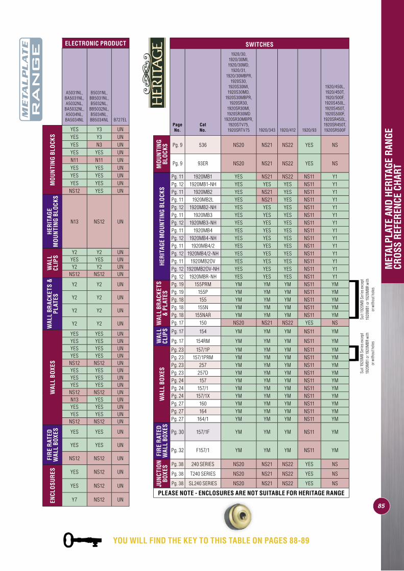
85
MET
ALPL
ATE
AND
HERI
TAGE
RAN
GE
CROS
S RE
FERE
NCE
CHAR
T
ELECTRONIC PRODUCT
A5031NL, BA5031NL, A5032NL,
BA5032NL, A5034NL, BA5034NL
B5031NL, BB5031NL, B5032NL,
BB5032NL, B5034NL, BB5034NL B727EL
MO
UN
TIN
G B
LOCK
S
YES Y3 UNYES Y3 UNYES N3 UNYES YES UNN11 N11 UNYES YES UNYES YES UNYES YES UN
NS12 YES UN
HER
ITAG
E M
OU
NTI
NG
BLO
CKS
N13 NS12 UN
WAL
L CL
IPS
Y2 Y2 UNYES YES UNY2 Y2 UN
NS12 NS12 UN
WAL
L BR
ACKE
TS &
PL
ATES
Y2 Y2 UN
Y2 Y2 UN
Y2 Y2 UN
Y2 Y2 UN
WAL
L BO
XES
YES YES UNYES YES UNYES YES UNYES YES UN
NS12 NS12 UNYES YES UNYES YES UNYES YES UN
NS12 NS12 UNN13 YES UNYES YES UNYES YES UN
NS12 NS12 UN
FIR
E R
ATED
W
ALL
BOXE
S YES YES UN
YES YES UN
NS12 NS12 UN
ENCL
OSU
RES YES NS12 UN
YES NS12 UN
Y7 NS12 UN
SWITCHES
Page No.
Cat No.
1920/30, 1920/30MI, 1920/30MD,
1920/31, 1920/30MBPR,
1920S30, 1920S30MI, 1920S30MD,
1920S30MBPR, 1920SR30,
1920SR30MI, 1920SR30MD
1920SR30MBPR, 1920STV75, 1920SRTV75 1920/343 1920/412 1920/93
1920/450L, 1920/450T, 1920/500F, 1920S450L, 1920S450T, 1920S500F,
1920SR450L, 1920SR450T, 1920SR500F
MO
UN
TIN
G BL
OCK
S Pg. 9 536 NS20 NS21 NS22 YES NS
Pg. 9 93ER NS20 NS21 NS22 YES NSH
ERIT
AGE
MO
UN
TIN
G BL
OCK
S
Pg. 11 1920MB1 YES NS21 NS22 NS11 Y1Pg. 12 1920MB1-NH YES YES YES NS11 Y1Pg. 11 1920MB2 YES NS21 YES NS11 Y1Pg. 11 1920MB2L YES NS21 YES NS11 Y1Pg. 12 1920MB2-NH YES YES YES NS11 Y1Pg. 11 1920MB3 YES YES YES NS11 Y1Pg. 12 1920MB3-NH YES YES YES NS11 Y1Pg. 11 1920MB4 YES YES YES NS11 Y1Pg. 12 1920MB4-NH YES YES YES NS11 Y1Pg. 11 1920MB4/2 YES YES YES NS11 Y1Pg. 12 1920MB4/2-NH YES YES YES NS11 Y1Pg. 11 1920MB2OV YES YES YES NS11 Y1Pg. 12 1920MB2OV-NH YES YES YES NS11 Y1Pg. 12 1920MBR-NH YES YES YES NS11 Y1
WAL
L BR
ACKE
TS
& P
LATE
S
Pg. 19 155PRM YM YM YM NS11 YMPg. 19 155P YM YM YM NS11 YMPg. 18 155 YM YM YM NS11 YMPg. 18 155N YM YM YM NS11 YMPg. 18 155NAR YM YM YM NS11 YMPg. 17 150 NS20 NS21 NS22 YES NS
WAL
L CL
IPS Pg. 17 154 YM YM YM NS11 YM
Pg. 17 154RM YM YM YM NS11 YM
WAL
L BO
XES
Pg. 23 157/1P YM YM YM NS11 YMPg. 23 157/1PRM YM YM YM NS11 YMPg. 23 257 YM YM YM NS11 YMPg. 23 257D YM YM YM NS11 YMPg. 24 157 YM YM YM NS11 YMPg. 24 157/1 YM YM YM NS11 YMPg. 24 157/1X YM YM YM NS11 YMPg. 27 160 YM YM YM NS11 YMPg. 27 164 YM YM YM NS11 YMPg. 27 164/1 YM YM YM NS11 YM
FIR
E R
ATED
W
ALL
BOXE
S
Pg. 30 157/1F YM YM YM NS11 YM
Pg. 32 F157/1 YM YM YM NS11 YM
JUN
CTIO
N BO
XES Pg. 38 240 SERIES NS20 NS21 NS22 YES NS
Pg. 38 T240 SERIES NS20 NS21 NS22 YES NS
Pg. 38 SL240 SERIES NS20 NS21 NS22 YES NS
PLEASE NOTE - ENCLOSURES ARE NOT SUITABLE FOR HERITAGE RANGE
Suit
1920
MB
Serie
s exc
ept
1920
MB1
or 1
920M
BR w
ith
or w
ithou
t hol
es
Suit
1920
MB
Serie
s exc
ept
1920
MB1
or 1
920M
BR w
ith
or w
ithou
t hol
es
YOU WILL FIND THE KEY TO THIS TABLE ON PAGES 88-89
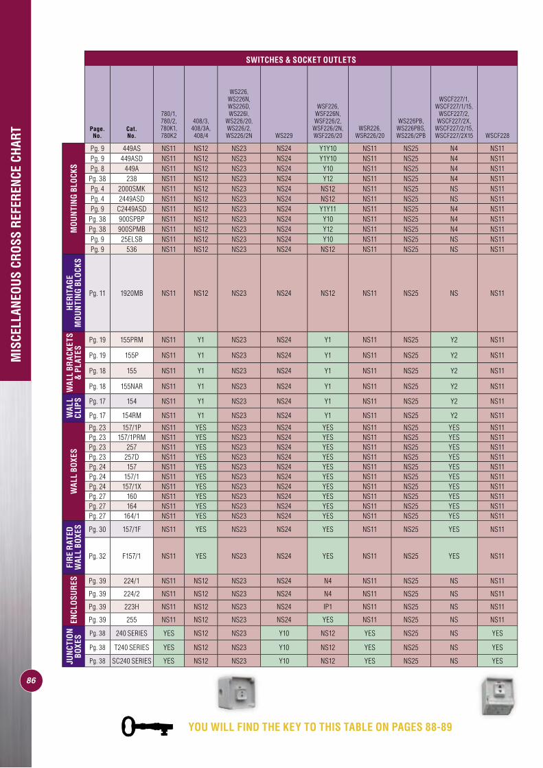
86
MIS
CELL
ANEO
US C
ROSS
REF
EREN
CE C
HART
SWITCHES & SOCKET OUTLETS
Page. No.
Cat. No.
780/1, 780/2, 780K1, 780K2
408/3, 408/3A, 408/4
WS226, WS226N, WS226D, WS226I,
WS226/20, WS226/2, WS226/2N WS229
WSF226, WSF226N, WSF226/2,
WSF226/2N, WSF226/20
WSR226, WSR226/20
WS226PB, WS226PBS, WS226/2PB
WSCF227/1, WSCF227/1/15,
WSCF227/2, WSCF227/2X,
WSCF227/2/15, WSCF227/2X15 WSCF228
MO
UN
TIN
G BL
OCK
S
Pg. 9 449AS NS11 NS12 NS23 NS24 Y1Y10 NS11 NS25 N4 NS11Pg. 9 449ASD NS11 NS12 NS23 NS24 Y1Y10 NS11 NS25 N4 NS11Pg. 8 449A NS11 NS12 NS23 NS24 Y10 NS11 NS25 N4 NS11Pg. 38 238 NS11 NS12 NS23 NS24 Y12 NS11 NS25 N4 NS11Pg. 4 2000SMK NS11 NS12 NS23 NS24 NS12 NS11 NS25 NS NS11Pg. 4 2449ASD NS11 NS12 NS23 NS24 NS12 NS11 NS25 NS NS11Pg. 9 C2449ASD NS11 NS12 NS23 NS24 Y1Y11 NS11 NS25 N4 NS11
Pg. 38 900SPBP NS11 NS12 NS23 NS24 Y10 NS11 NS25 N4 NS11Pg. 38 900SPMB NS11 NS12 NS23 NS24 Y12 NS11 NS25 N4 NS11Pg. 9 25ELSB NS11 NS12 NS23 NS24 Y10 NS11 NS25 NS NS11Pg. 9 536 NS11 NS12 NS23 NS24 NS12 NS11 NS25 NS NS11
HER
ITAG
E M
OU
NTI
NG
BLO
CKS
Pg. 11 1920MB NS11 NS12 NS23 NS24 NS12 NS11 NS25 NS NS11
WAL
L BR
ACKE
TS
& P
LATE
S
Pg. 19 155PRM NS11 Y1 NS23 NS24 Y1 NS11 NS25 Y2 NS11
Pg. 19 155P NS11 Y1 NS23 NS24 Y1 NS11 NS25 Y2 NS11
Pg. 18 155 NS11 Y1 NS23 NS24 Y1 NS11 NS25 Y2 NS11
Pg. 18 155NAR NS11 Y1 NS23 NS24 Y1 NS11 NS25 Y2 NS11
WAL
L CL
IPS Pg. 17 154 NS11 Y1 NS23 NS24 Y1 NS11 NS25 Y2 NS11
Pg. 17 154RM NS11 Y1 NS23 NS24 Y1 NS11 NS25 Y2 NS11
WAL
L BO
XES
Pg. 23 157/1P NS11 YES NS23 NS24 YES NS11 NS25 YES NS11Pg. 23 157/1PRM NS11 YES NS23 NS24 YES NS11 NS25 YES NS11Pg. 23 257 NS11 YES NS23 NS24 YES NS11 NS25 YES NS11Pg. 23 257D NS11 YES NS23 NS24 YES NS11 NS25 YES NS11Pg. 24 157 NS11 YES NS23 NS24 YES NS11 NS25 YES NS11Pg. 24 157/1 NS11 YES NS23 NS24 YES NS11 NS25 YES NS11Pg. 24 157/1X NS11 YES NS23 NS24 YES NS11 NS25 YES NS11Pg. 27 160 NS11 YES NS23 NS24 YES NS11 NS25 YES NS11Pg. 27 164 NS11 YES NS23 NS24 YES NS11 NS25 YES NS11Pg. 27 164/1 NS11 YES NS23 NS24 YES NS11 NS25 YES NS11
FIR
E R
ATED
W
ALL
BOXE
S Pg. 30 157/1F NS11 YES NS23 NS24 YES NS11 NS25 YES NS11
Pg. 32 F157/1 NS11 YES NS23 NS24 YES NS11 NS25 YES NS11
ENCL
OSU
RES Pg. 39 224/1 NS11 NS12 NS23 NS24 N4 NS11 NS25 NS NS11
Pg. 39 224/2 NS11 NS12 NS23 NS24 N4 NS11 NS25 NS NS11
Pg. 39 223H NS11 NS12 NS23 NS24 IP1 NS11 NS25 NS NS11
Pg. 39 255 NS11 NS12 NS23 NS24 YES NS11 NS25 NS NS11
JUN
CTIO
N BO
XES Pg. 38 240 SERIES YES NS12 NS23 Y10 NS12 YES NS25 NS YES
Pg. 38 T240 SERIES YES NS12 NS23 Y10 NS12 YES NS25 NS YES
Pg. 38 SC240 SERIES YES NS12 NS23 Y10 NS12 YES NS25 NS YES
YOU WILL FIND THE KEY TO THIS TABLE ON PAGES 88-89
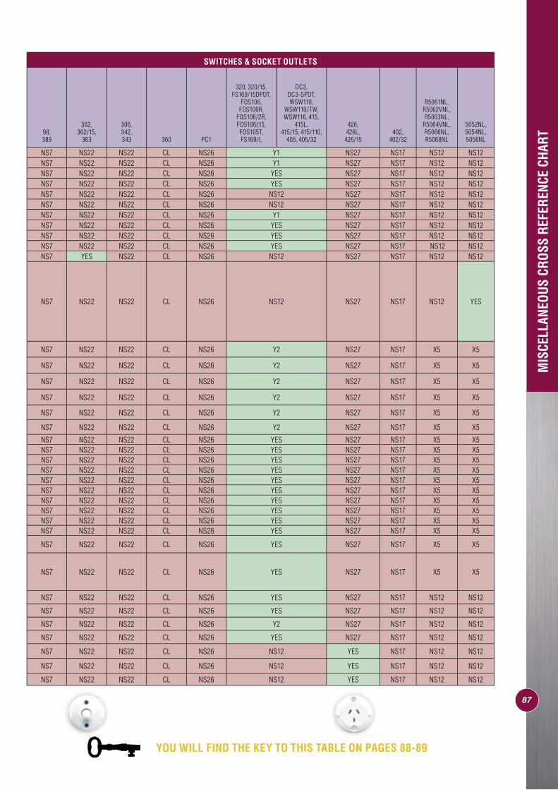
87
MIS
CELL
ANEO
US C
ROSS
REF
EREN
CE C
HART
SWITCHES & SOCKET OUTLETS
98, 389
362, 362/15,
363
306, 342, 343 360 PC1
320, 320/15, FS169/15DPDT,
FOS106, FOS106R,
FOS106/2R, FOS106/15, FOS105T, FS169/I,
DC3, DC3-SPDT, WSW110,
WSW110/TW, WSW116, 415,
415L, 415/15, 415/110,
405, 405/32
426, 426L,
426/15402,
402/32
R5061NL, R5062VNL, R5063NL,
R5064VNL, R5066NL, R5068NL
5052NL, 5054NL, 5056NL
NS7 NS22 NS22 CL NS26 Y1 NS27 NS17 NS12 NS12NS7 NS22 NS22 CL NS26 Y1 NS27 NS17 NS12 NS12NS7 NS22 NS22 CL NS26 YES NS27 NS17 NS12 NS12NS7 NS22 NS22 CL NS26 YES NS27 NS17 NS12 NS12NS7 NS22 NS22 CL NS26 NS12 NS27 NS17 NS12 NS12NS7 NS22 NS22 CL NS26 NS12 NS27 NS17 NS12 NS12NS7 NS22 NS22 CL NS26 Y1 NS27 NS17 NS12 NS12NS7 NS22 NS22 CL NS26 YES NS27 NS17 NS12 NS12NS7 NS22 NS22 CL NS26 YES NS27 NS17 NS12 NS12NS7 NS22 NS22 CL NS26 YES NS27 NS17 NS12 NS12NS7 YES NS22 CL NS26 NS12 NS27 NS17 NS12 NS12
NS7 NS22 NS22 CL NS26 NS12 NS27 NS17 NS12 YES
NS7 NS22 NS22 CL NS26 Y2 NS27 NS17 X5 X5
NS7 NS22 NS22 CL NS26 Y2 NS27 NS17 X5 X5
NS7 NS22 NS22 CL NS26 Y2 NS27 NS17 X5 X5
NS7 NS22 NS22 CL NS26 Y2 NS27 NS17 X5 X5
NS7 NS22 NS22 CL NS26 Y2 NS27 NS17 X5 X5
NS7 NS22 NS22 CL NS26 Y2 NS27 NS17 X5 X5
NS7 NS22 NS22 CL NS26 YES NS27 NS17 X5 X5NS7 NS22 NS22 CL NS26 YES NS27 NS17 X5 X5NS7 NS22 NS22 CL NS26 YES NS27 NS17 X5 X5NS7 NS22 NS22 CL NS26 YES NS27 NS17 X5 X5NS7 NS22 NS22 CL NS26 YES NS27 NS17 X5 X5NS7 NS22 NS22 CL NS26 YES NS27 NS17 X5 X5NS7 NS22 NS22 CL NS26 YES NS27 NS17 X5 X5NS7 NS22 NS22 CL NS26 YES NS27 NS17 X5 X5NS7 NS22 NS22 CL NS26 YES NS27 NS17 X5 X5NS7 NS22 NS22 CL NS26 YES NS27 NS17 X5 X5
NS7 NS22 NS22 CL NS26 YES NS27 NS17 X5 X5
NS7 NS22 NS22 CL NS26 YES NS27 NS17 X5 X5
NS7 NS22 NS22 CL NS26 YES NS27 NS17 NS12 NS12
NS7 NS22 NS22 CL NS26 YES NS27 NS17 NS12 NS12
NS7 NS22 NS22 CL NS26 Y2 NS27 NS17 NS12 NS12
NS7 NS22 NS22 CL NS26 YES NS27 NS17 NS12 NS12
NS7 NS22 NS22 CL NS26 NS12 YES NS17 NS12 NS12
NS7 NS22 NS22 CL NS26 NS12 YES NS17 NS12 NS12
NS7 NS22 NS22 CL NS26 NS12 YES NS17 NS12 NS12
YOU WILL FIND THE KEY TO THIS TABLE ON PAGES 88-89
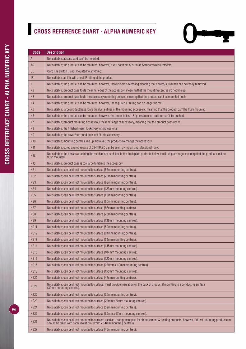
88
Code Description
A Not suitable; access card can’t be inserted.
AS Not suitable; the product can be mounted, however, it will not meet Australian Standards requirements.
CL Cord line switch (is not mounted to anything).
IP1 Not suitable: as this will affect IP rating of the product.
N Not suitable; the product can be mounted, however, there is some overhang meaning that covers/surrounds can be easily removed.
N2 Not suitable; product base fouls the inner edge of the accessory, meaning that the mounting centres do not line up.
N3 Not suitable; product base fouls the accessory mounting bosses, meaning that the product can’t be mounted fl ush.
N4 Not suitable; the product can be mounted, however, the required IP rating can no longer be met.
N5 Not suitable; large product base fouls the duct entries of the mounting accessory, meaning that the product can’t be fl ush mounted.
N6 Not suitable; the product can be mounted, however, the ‘press to test’ & ‘press to reset’ buttons can’t be pushed.
N7 Not suitable; product mounting bosses foul the inner edge of accessory, meaning that the product does not fi t.
N8 Not suitable; the fi nished result looks very unprofessional.
N9 Not suitable; the cover/surround does not fi t into accessory.
N10 Not suitable; mounting centres line up, however, the product overhangs the accessory.
N11 Not suitable; cored angled recess of C2449ASD can be seen, giving an unprofessional look.
N12 Not suitable; the bosses attaching the mechanism back box to the fl ush plate protrude below the fl ush plate edge, meaning that the product can’t be fl ush mounted.
N13 Not suitable; product base is too large to fi t into the accessory.
NS1 Not suitable; can be direct mounted to surface (55mm mounting centres).
NS2 Not suitable; can be direct mounted to surface (70mm mounting centres).
NS3 Not suitable; can be direct mounted to surface (98mm mounting centres).
NS4 Not suitable; can be direct mounted to surface (123mm mounting centres).
NS5 Not suitable; can be direct mounted to surface (40mm mounting centres).
NS6 Not suitable; can be direct mounted to surface (60mm mounting centres).
NS7 Not suitable; can be direct mounted to surface (87mm mounting centres).
NS8 Not suitable; can be direct mounted to surface (78mm mounting centres).
NS9 Not suitable; can be direct mounted to surface (136mm mounting centres).
NS11 Not suitable; can be direct mounted to surface (50mm mounting centres).
NS12 Not suitable; can be direct mounted to surface (84mm mounting centres).
NS13 Not suitable; can be direct mounted to surface (75mm mounting centres).
NS14 Not suitable; can be direct mounted to surface (145mm mounting centres).
NS15 Not suitable; can be direct mounted to surface (104mm mounting centres).
NS16 Not suitable; can be direct mounted to surface (120mm mounting centres).
NS17 Not suitable; can be direct mounted to surface (230mm x 40mm mounting centres).
NS18 Not suitable; can be direct mounted to surface (153mm mounting centres).
NS20 Not suitable; can be direct mounted to surface (42mm mounting centres).
NS21 Not suitable; can be direct mounted to surface; must provide insulation on the back of product if mounting to a conductive surface (39mm mounting centres).
NS22 Not suitable; can be direct mounted to surface (35mm mounting centres).
NS23 Not suitable; can be direct mounted to surface (70mm x 70mm mounting centres).
NS24 Not suitable; can be direct mounted to surface (52mm mounting centres).
NS25 Not suitable; can be direct mounted to surface (66mm x 57mm mounting centres).
NS26 Not suitable; can be direct mounted to surface; used as a component part for air movement & heating products, however if direct mounting product care should be taken with cable isolation (32mm x 34mm mounting centres).
NS27 Not suitable; can be direct mounted to surface (48mm mounting centres).
CROS
S RE
FERE
NCE
CHAR
T - A
LPHA
NUM
ERIC
KEY
CROSS REFERENCE CHART - ALPHA NUMERIC KEY
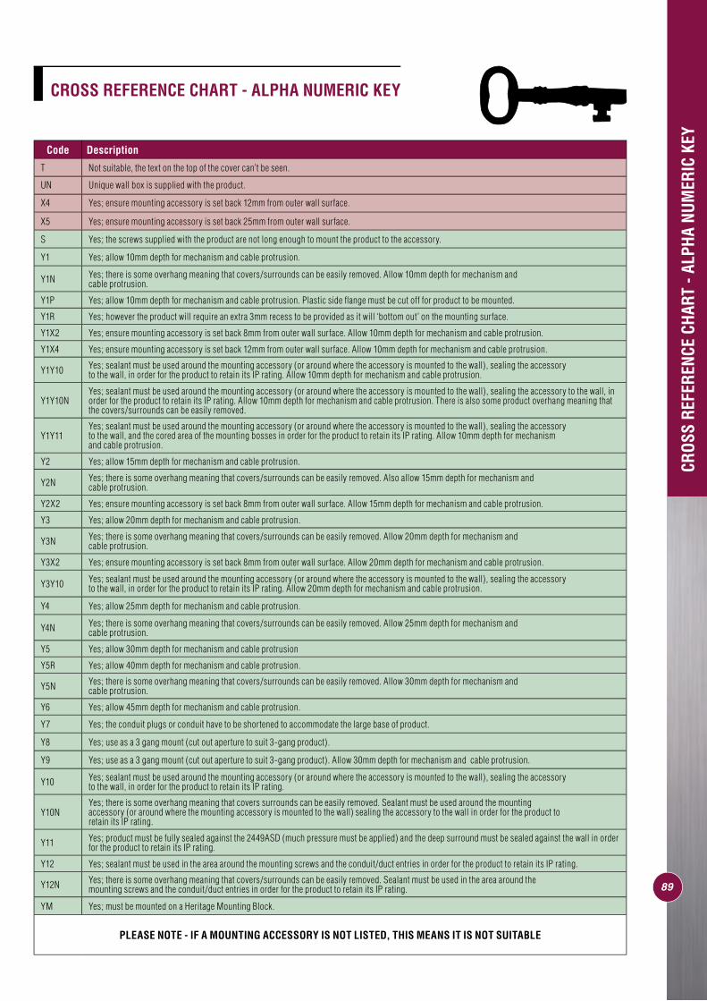
89
Code Description
T Not suitable, the text on the top of the cover can’t be seen.
UN Unique wall box is supplied with the product.
X4 Yes; ensure mounting accessory is set back 12mm from outer wall surface.
X5 Yes; ensure mounting accessory is set back 25mm from outer wall surface.
S Yes; the screws supplied with the product are not long enough to mount the product to the accessory.
Y1 Yes; allow 10mm depth for mechanism and cable protrusion.
Y1N Yes; there is some overhang meaning that covers/surrounds can be easily removed. Allow 10mm depth for mechanism and cable protrusion.
Y1P Yes; allow 10mm depth for mechanism and cable protrusion. Plastic side fl ange must be cut off for product to be mounted.
Y1R Yes; however the product will require an extra 3mm recess to be provided as it will ‘bottom out’ on the mounting surface.
Y1X2 Yes; ensure mounting accessory is set back 8mm from outer wall surface. Allow 10mm depth for mechanism and cable protrusion.
Y1X4 Yes; ensure mounting accessory is set back 12mm from outer wall surface. Allow 10mm depth for mechanism and cable protrusion.
Y1Y10 Yes; sealant must be used around the mounting accessory (or around where the accessory is mounted to the wall), sealing the accessory to the wall, in order for the product to retain its IP rating. Allow 10mm depth for mechanism and cable protrusion.
Y1Y10NYes; sealant must be used around the mounting accessory (or around where the accessory is mounted to the wall), sealing the accessory to the wall, in order for the product to retain its IP rating. Allow 10mm depth for mechanism and cable protrusion. There is also some product overhang meaning that the covers/surrounds can be easily removed.
Y1Y11Yes; sealant must be used around the mounting accessory (or around where the accessory is mounted to the wall), sealing the accessory to the wall, and the cored area of the mounting bosses in order for the product to retain its IP rating. Allow 10mm depth for mechanism and cable protrusion.
Y2 Yes; allow 15mm depth for mechanism and cable protrusion.
Y2N Yes; there is some overhang meaning that covers/surrounds can be easily removed. Also allow 15mm depth for mechanism and cable protrusion.
Y2X2 Yes; ensure mounting accessory is set back 8mm from outer wall surface. Allow 15mm depth for mechanism and cable protrusion.
Y3 Yes; allow 20mm depth for mechanism and cable protrusion.
Y3N Yes; there is some overhang meaning that covers/surrounds can be easily removed. Allow 20mm depth for mechanism and cable protrusion.
Y3X2 Yes; ensure mounting accessory is set back 8mm from outer wall surface. Allow 20mm depth for mechanism and cable protrusion.
Y3Y10 Yes; sealant must be used around the mounting accessory (or around where the accessory is mounted to the wall), sealing the accessory to the wall, in order for the product to retain its IP rating. Allow 20mm depth for mechanism and cable protrusion.
Y4 Yes; allow 25mm depth for mechanism and cable protrusion.
Y4N Yes; there is some overhang meaning that covers/surrounds can be easily removed. Allow 25mm depth for mechanism and cable protrusion.
Y5 Yes; allow 30mm depth for mechanism and cable protrusion
Y5R Yes; allow 40mm depth for mechanism and cable protrusion.
Y5N Yes; there is some overhang meaning that covers/surrounds can be easily removed. Allow 30mm depth for mechanism and cable protrusion.
Y6 Yes; allow 45mm depth for mechanism and cable protrusion.
Y7 Yes; the conduit plugs or conduit have to be shortened to accommodate the large base of product.
Y8 Yes; use as a 3 gang mount (cut out aperture to suit 3-gang product).
Y9 Yes; use as a 3 gang mount (cut out aperture to suit 3-gang product). Allow 30mm depth for mechanism and cable protrusion.
Y10 Yes; sealant must be used around the mounting accessory (or around where the accessory is mounted to the wall), sealing the accessory to the wall, in order for the product to retain its IP rating.
Y10NYes; there is some overhang meaning that covers surrounds can be easily removed. Sealant must be used around the mounting accessory (or around where the mounting accessory is mounted to the wall) sealing the accessory to the wall in order for the product to retain its IP rating.
Y11 Yes; product must be fully sealed against the 2449ASD (much pressure must be applied) and the deep surround must be sealed against the wall in order for the product to retain its IP rating.
Y12 Yes; sealant must be used in the area around the mounting screws and the conduit/duct entries in order for the product to retain its IP rating.
Y12N Yes; there is some overhang meaning that covers/surrounds can be easily removed. Sealant must be used in the area around the mounting screws and the conduit/duct entries in order for the product to retain its IP rating.
YM Yes; must be mounted on a Heritage Mounting Block.
PLEASE NOTE - IF A MOUNTING ACCESSORY IS NOT LISTED, THIS MEANS IT IS NOT SUITABLE
CROS
S RE
FERE
NCE
CHAR
T - A
LPHA
NUM
ERIC
KEY
CROSS REFERENCE CHART - ALPHA NUMERIC KEY

������������������
������������������������
�����������
������������������������
������������������������������������������������������������������������������������������������������
������������������
��������������������������������������
������������������������������������������������������������������������������������������������������������������������������������������������������������������������������������������������������������������������������������������������
���
�����������
90
2000H32000/32000/2
To make installation of the Multigang Surrounds easier, there are a range of wall Clips, wall Brackets and wall Boxes available that are dedicated to each surround. Refer to the back page cross reference chart or your Clipsal representative for more information.
• a choice of colours to mix and match with gridplates and contrast or blend with any décor
• a design that neatly conceals all mounting holes
• a durable high gloss fi nish for easy cleaning
• a clever clip on/clip off design that enables surrounds to be easily removed when redecorating to conceal overpainting or untidy cut marks when wallpapering
• a spacing gauge to assist with mounting.
All 2000 Series Multigang Surrounds feature:
Horizontal Surrounds2000H2 Two gang horizontal fl ush surround
2000H3 Three gang horizontal fl ush surround
Vertical Surrounds2000/2 Two gang vertical fl ush surround
2000/3 Three gang vertical fl ush surround
2000/4 Four gang vertical fl ush surround
Cat. No. Description
2000H2
2000/4
Note: Where different wiring systems are terminated within the one enclosure, segregation may need to be provided. Refer AS/NZS 3000 - 2000 Clause 1.7.4.5.3.
Multigang Surrounds -altogether betterThe neatest way to keep your switches and sockets together is with Clipsal 2000 Series Multigang Surrounds.
Available in two and three gang horizontal versions and two, three and four gang vertical versions, they neatly house and fully integrate all 2000 Series gridplates into a single surround.
Horizontal versions are ideal when extra space is required for oversized plugs (note picture below).
For commercial environments with several circuits, Clipsal offers two and three gang horizontal multigang surrounds with provision for Clipsal 2009R Circuit Identifi cation Caps. (See opposite page).

Cat. No. 2009 This oval identifi cation cap is located in a 2000 Series grid mounting screw hole and remains hidden behind the clip-on surround. 2009 caps are supplied blank as standard, but are also available to special order with specifi c identifi cation information.
Cat. No. 2009R This circular cap is located in a 2000 Series grid mounting screw hole and used in conjunction with an 'R' designated surround. 'R' surrounds have an opening which fi ts over the 2009R so that the ID cap is always visible. 2009R caps are supplied blank as standard, but are available to special order with specifi c identifi cation information.
Cat. No. 2000R The 2000R is a 2000 Series surround with a pierced aperture to suit the 2009R identifi cation cap. Standard confi guration is for the apertures to align with the top right or bottom left hand corner of the horizontal gridplate. Other confi gurations are available to special order.
Cat. No. 2000/2R This product is a standard 2000 Series two gang surround with two pierced apertures to suit the 2009R identifi cation cap. Standard confi guration is for the apertures to align with the top right or bottom left corner of the horizontal gridplate. Other confi gurations are available to special order.
Cat. No. 2000/3R The 2000/3R is a standard 2000 Series three gang surround with three pierced apertures to suit the 2009R identifi cation cap. Standard confi guration is for the apertures to align with the top right or bottom left corner of the horizontal gridplate. Other confi gurations are available to special order.
PRODUCT RANGE
Cat. Nos. 2009, 2009R, 2000R, 2000/2R & 2000/3R
With the ever increasing popularity of the 2000 Series switch plates in domestic and commercial environments, Clipsal provides a range of low cost circuit ID caps that are as adaptable as the locations in which they are used.
Clipsal's 2000 Series ID caps can be hidden under the 2000 Series surround in situations where the information needs to be accessible but not obvious, or displayed in specially designed 2000 Series surrounds that have pierced apertures for instant circuit identifi cation.
2000 Series circuit ID caps in a range of options
Concealed
Visible
Multigang Surround & Mounting Accessories Cross Reference Chart
MULTIGANG WALL CLIPS WALL BRACKETS & PLATES WALL BOXES FIRE RATED
WALL BOXES
Vertical Surrounds
2000/2Two gang vertical fl ush surround 2154/2 2155PRM2 2157/2 &
2157/2SB2157/2F & 2157/2FSB
2000/3Three gang vertical fl ush surround 2154/3 2155PRM3 2157/3, 2157/3SB1
& 2157/3SB22157/3F, 2157/3FSB1 &
2157/3FSB2
2000/4Four gang vertical fl ush surround 2154/4 2155PRM4 2157/4 N/A
Horizontal Surrounds
2000H2Two gang horizontal fl ush surround 2154H2 2155PHRM2 2157H2 N/A
2000H3Three gang horizontal fl ush surround 2154H3 2155PHRM3 2157H3 N/A
Note: All wall boxes listed can be purchased with or without one or two segregation barriers, when mixing circuits (eg data & power). This is identifi ed in part number by SB & SB1 (includes one segregation barrier) or SB2 (includes two segregation barriers).
91
More Multigang Surround information can be found on pages 4 & 5

Refer to page 40 of this brochure for more information on Cablemate.
Your best mate when it comes to keeping cabling and conduits in line.
Distribution Board Wiring
Data Cabinet Installations
Roof CavityWiring
Turns Corners Effortlessly
Keeps Desks Uncluttered

The shape of the switch dolly is a trade mark of Clipsal Australia Pty. Ltd.
tech
nica
l da
ta
clipsal.com
behindthe
scene
Workinghard
tech
nica
l da
ta
Working
MO
UN
TIN
G A
CC
ES
SO
RIE
S -
Wo
rkin
g H
ard
Beh
ind
Th
e S
cen
eO
/N 8
93 0
26
Au
gu
st 0
6/02
Special thanks to Graham Ward (Active Connection Electrical) and Greg Spurling (Spurling Electrical) for their contribution to this catalogue.
clipsal.com
Clipsal Australia Pty Ltd reserves the right to change specifi cations, modify designs and dis con tin ue items without incurring obligation and whilst every effort is made to ensure that descriptions, specifi cations and other in for ma tion in this catalogue are correct, no warranty is given in respect thereof and the company shall not be liable for any error therein.
Product of Clipsal Australia Pty LtdABN 27 007 873 529
Head Offi ce12 Park Terrace, Bowden South Australia 5007Telephone (08) 8269 0511Facsimile (08) 8340 1724Internet clipsal.comE-Mail [email protected]
National Customer Service Enquiries:1300 2025 25National Customer Service Facsimile:1300 2025 56Area RepresentativesNSW Albury (02) 6051 2377 Central 0418 430 361 Coffs Harbour 0418 653 183 Dubbo 0418 822 564 Newcastle 0407 298 792 0418 434 169 0418 686 040 Tamworth 0417 714 339 Wagga Wagga 0418 578 903 Wollongong 0418 423 581
ACT Canberra 0419 238 824 0418 164 070
VIC Bendigo 0418 570 213 Ballarat 0418 336 291 Mornington Peninsula 0407 795 291 Geelong 0418 527 233 Gippsland 0418 512 680 Western Victoria 0419 380 444
QLD Cairns 0418 773 254 Mackay 0418 752 134 Maryborough 0418 664 338 Northern Rivers 0418 768 902 Rockhampton 0419 869 752 Sunshine Coast 0418 711 786 Toowoomba 0418 726 394 Townsville 0418 180 372
WA Bunbury 0418 931 684 Kalgoorlie & 0417 928 981 Eastern Gold Fields Karratha 0418 937 249
SA Riverland/Mildura/ Broken Hill 0418 596 145
NT Darwin 0417 454 411
TAS 0400 979 340
Clipsal Australia Pty Ltd reserves the right to change specifi cations, modify designs and dis con tin ue items without incurring obligation and whilst every effort is made to ensure that descriptions, specifi cations and other in for ma tion in this catalogue are correct, no warranty is given in respect thereof and the company shall not be liable for any error therein.
You can fi nd this brochure and many others online in PDF format at: clipsal.comFollow the links off the home page or access the following page directly: clipsal.com/wat_lib_pdf.cfm
clipsal.com
International Enquiries
International Sales and MarketingTelephone + 61 8 8269 0587Facsimile + 61 8 8340 7350E-Mail [email protected]
New ZealandClipsal Industries (NZ) LtdTelephone (09) 576 3403Facsimile (09) 576 1015E-Mail headoffi [email protected]
Customer ServiceFree Fax (0508) 250 305Auckland/Mobile Phone (09) 572 0014Free Phone (0508) CLIPSAL 2547725
©Copyright Clipsal Australia Pty Ltd 2006.All rights reserved.This material is copyright under Australian and international laws. Except as permitted under the relevant law, no part of this work may be reproduced by any process without prior written permission of and acknowledgement to Clipsal Australia Pty Ltd. C
1-00
4
O/N 893 026CLIPCOM 11345 August 2006