MOUNTAIN BIKE REAR SUSPENSIONweb.cecs.pdx.edu/~far/me492/Progress report...
21
PORTLAND STATE UNIVERSITY MECHANICAL ENGINEERING MOUNTAIN BIKE REAR SUSPENSION WINTER TERM PROGRESS REPORT March 12 nd 2004 GROUP MEMBERS : HEATHER LANDIS LUTHER BEALE CHRIS POLINSKY DAVID HARRIS ACADEMIC ADVISOR : DR. CHIEN WERN
Transcript of MOUNTAIN BIKE REAR SUSPENSIONweb.cecs.pdx.edu/~far/me492/Progress report...

PORTLAND STATE UNIVERSITY
MECHANICAL ENGINEERING
MOUNTAIN BIKE REAR SUSPENSION
WINTER TERM PROGRESS REPORT
March 12nd 2004
GROUP MEMBERS: HEATHER LANDIS LUTHER BEALE
CHRIS POLINSKY DAVID HARRIS
ACADEMIC ADVISOR:
DR. CHIEN WERN

1
Table of Contents
Table of Contents............................................................................................ 1
Introduction..................................................................................................... 2
Mission Statement........................................................................................... 2
Project Plan ..................................................................................................... 2
Product Design Specifications ........................................................................ 3
Research.......................................................................................................... 5
Direct Competition Products ....................................................................... 5
Existing Related Products ........................................................................... 6
Existing Related Technology ...................................................................... 6
Existing Technology for Product Sub-Functions........................................ 7
Concept Development..................................................................................... 7
Concept Selection ........................................................................................... 8
Decision Matrix ........................................................................................... 9
Eliminated Concepts.................................................................................... 9
Primary Concept........................................................................................ 10
Progress on detailed design........................................................................... 10
Conclusion .................................................................................................... 11
Appendix A (Product Design Criteria) ......................................................... 12
Appendix B (Research Sources) ................................................................... 15
United States Patents ................................................................................. 15
Web Pages ................................................................................................. 16
Appendix C (Concepts) ................................................................................ 17
Appendix D (Gant Chart) ............................................................................. 20

2
Introduction Presented in this report is the progress for the Portland State University Mountain
Bike Rear Suspension Design Project. This project presents a unique challenge as it was
not presented by an existing manufacturer, and had minimal predefined design goals. For
this reason much of the research phase involved defining the projects goals and refining
the product design specifications.
Current full suspension mountain bikes provide riders a smother ride with
increased traction over rough terrain by sacrificing some of the energy input by the rider
to the system. The inefficiency of the current systems is due to the system not being able
to decipher the input from the rider versus the input from the terrain. Attempts to
accomplish this have been approached in many different forms. The key design factors
of concern are a comfortable ride, light weight, suspension performance, positive anti-
squat, and reduced bump feedback.
Mission Statement To Design a new mountain bike rear suspension system that maximizes response
to terrain inputs while minimizing response to pedaling inputs. The team intends to
present a working prototype of an innovative rear suspension system for a mountain bike
by the end of May. The suspension system will operate better than existing systems in a
light weight design in order to provide the avid mountain biker a more comfortable ride
with better control.
Project Plan Outlined in this section are the milestones and projected completion dates for the
remaining design goals. All future scheduled design items are subject to change.
1/26 – Marked the completion of the external research phase and the product
design specifications presentation.
2/2 – On this date the external search results were presented and the internal
search process of brainstorming began.

3
2/9 – The concepts developed during the internal search were presented on this
date and the process of ranking them began.
2/23 – The final selection for the design concept was presented.
2/23-3/10 – Over this time period the final concept was further studied and
refined.
3/10-4/12 – During the time between the end of winter term and the second week
of spring term the primary design will be analyzed and computer modeled for
simulation.
4/14-4/30 – Once the analysis is complete and working drawings are finalized the
suspension system will be Prototyped and be subjected to physical testing.
5/1-5/30 – During the final month of the project the suspension system will be
constructed and tuned.
Product Design Specifications The design specifications were developed for this project in conjunction with the
external research. As the project became better defined the team was able to establish the
criteria that the suspension system should meet for both rider and manufacturer, see
Appendix A. The following are the key criteria established for the design which were
later used in the selection process of the primary design concept.
Performance – This is an overall view of how the system would affect the overall
experience of riding the bike.
Input Differentiation – The ability of the suspension system to differentiate
between rider inputs and terrain inputs.

4
Adjustability – Whether or not the suspension system can accommodate various
rider sizes and/or various riding conditions.
Rearward Path – The system allows for rearward motion of the axle to absorb
initial impact and keep tension in the chain to prevent slap.
Bump Absorption – The suspension system must offer terrain absorption
equivalent to or better than competing systems. The team also considered
whether the system could absorb various sizes of bumps effectively.
Maintain constant seat height – The concern here, which ends up not being an
issue, was that a suspension system could not be implemented in such a way that
it would allow the distance between the crank and the seat to vary. This could
produce serious efficiency and comfort issues.
Minimization of chain growth – This originally was thought to be a major
concern as increased chain length would create a larger work load on the rider.
Upon further research it was determined that small scale chain growth can occur
virtually unnoticed by the rider.
Ease of implementation – This applies not only for the design team, but for
potential manufactures and installers. The system should not be harder to
implement than existing systems with similar performance.
Ease of maintenance – The rider should be able to perform regular maintenance
as easily as with existing suspension systems.
Light weight – The system should not add a disproportionate amount of weight
when compared to performance and existing systems.

5
Ease of manufacturing – The system should be constructed using techniques
familiar to the industry and use stock parts.
Aesthetics – The suspension system should look pleasing and not detract from the
overall appearance of the bike.
Innovative – The suspension system should be new and offer better performance
than existing systems.
Research Numerous sources were referenced for the external search. An extensive patent
search was conducted in which more than 30 patents were examined. Many of these are
listed in Appendix B of this document by number along with the title and holder of the
patent. The working principles used to design the systems developed in the patents were
categorized so that they could be evaluated and the patent that best represented each
principle be identified. Of the 30 original patents, approximately seven were further
evaluated as the best examples of their particular concepts. These seven patents are
represented with bold type in the list presented in Appendix B. Web pages, catalogues
and other consumer materials were referenced at this point in order to gain better
understanding of the systems currently in the market. Visits to bike shops were made so
that measurements and photographs of existing systems could be made. Finally, using
the data obtained from the research, Working Model was used to build accurate models
of several key existing designs. A detailed listing of the references for the external
source can be found in Appendix A.
Direct Competition Products Existing mountain bike rear suspension systems involve the use of several key
working principles. Through research, these principles were determined to be the
following:
Pivot location (if single pivot), or Instant Center location (if linkage)
Creation of positive anti-squat tendencies through the use of chain-growth

6
Rearward axle path
Radius of curvature for axle path greater than the distance from the bottom bracket to
rear axle
The bicycles that utilize these concepts include models manufactured by Santa
Cruz Bicycles, Maverick American Bicycles, Specialized Bicycle Corporation, and
Ellsworth Bicycles. These systems are among the best systems currently on the market.
However, all of the systems change the length of the tensioned chain under bump forces.
This creates a force that must be overcome by the rider in the form of an increased
pedaling force. No system currently on the market (or patented) adequately provides a
system that allows the bicycle suspension to freely move without interference with the
drive train of the bicycle. It is the goal of the design team to produce a system that
incorporates some (or all) of these key working principles while minimizing the effect of
the suspension on the drive train of the bicycle to a greater degree than afforded by
existing systems.
Existing Related Products Other related products using similar suspension systems to those utilized on
bicycles exist. These systems are found on other two wheeled vehicles such as
motorcycles and scooters. One significant difference in any of these systems is that the
vehicles have much greater power available to drive the rear wheel, so that losses due to
inefficiencies in the suspension are not nearly as significant. The designs for most of
these systems are correspondingly basic in comparison to the systems used on bicycles,
as the main concern is bump absorption.
Existing Related Technology Several other technologies exist in patents and production for solving issues related to
bicycle suspension performance and pedaling efficiency. One simple solution that does
not utilize a mechanical system attached to the rear wheel of the bicycle is a suspension
seat post. These devices limit vibration felt by the cyclist by allowing the seat to move in
response to bump forces. An advantage of these devices is that the efficiency of the
bicycle is not changed when it is equipped with a suspension seat post. Significant

7
disadvantages include the loss of performance benefits that are afforded to traditional
mechanical suspension systems. Another drawback is the change in leg length that
occurs in response to terrain input that results in efficiency losses. Another technology is
the use of active control systems to modify the suspension based on a variety of input
parameters. Generally, these devices are too heavy and complicated for practical
implementation on bicycles.
Existing Technology for Product Sub-Functions The design team intends that the project use off the shelf parts for the bicycle.
Currently there are many available shock and damper units that could be bolted onto the
design. This would enable the design to be upgraded or modified as needs of the user
change. Drive train components are also standardized; ideally the design will use a
standard drive train configuration. The choice of materials with specific properties could
be a technology for a sub-function of the device by allowing more flexibility at specific
points.
Concept Development The design criterion helped the team developed many new suspension design
concepts that could potentially accomplish the established goals. These ideas ranged from
fully modifying the rear frame to only modifying the tire. The team generated 6 main
ideas from the brainstorming sessions. These ideas are a linkage system, a swing arm
system, a flexible member system, a motor drive system, a flexible wheel system, and an
active control system.
The linkage system consists of multiple linkages that will allow the wheel to
move in predetermined pattern. This pattern would allow for more complex movement
of the rear wheel. In this type of system the more degrees of freedom the linkage
possesses, the more rearward the path can become and the more complex it will be to
manufacture and maintain. However the more complex movement would allow for
optimum bump absorption while maintaining system efficiency. The path would dictate
the performance of how the well the bumps would be absorbed. Two possible systems
are illustrated in Figures 1 and 2, in Appendix C.

8
The swing arm system is similar to a motorcycle rear suspension. It will allow for
bump absorption through an arc or radial movement. The swing arm is simple and easy
to manufacture and maintain. Figure 3, in Appendix C, shows a concept drawing of a
swing arm system.
The flexible member is a linkage that can flex in predetermined directions in
order to absorb small sized bumps. The flexible member would be a material that has
natural flexible properties such as a polymer or carbon fiber. A possible flexible member
system is displayed in Figure 4 of Appendix C.
A motor drive would eliminate the need for a chain, which would eliminate the
chain growth problem as the tire moves reward. Although this is a motor system the
operator would still be required to pedal the bicycle. The operator’s pedaling force would
directly drive a motor through a system of wires. The absence of mechanical linkages for
motion control is a concept used in the aviation industry called fly-by-wire, Figure 5 in
Appendix C.
The flexible wheel would absorb bumps without vibrating the frame. The wheel
would be able to absorb small to medium bumps before the frame would have to move.
Figure 6 is a drawing of a possible flexible wheel system.
The last system that was considered was a control system. This would consist of
an electrical sensor that would in turn control a valve in the shock absorber. The valve
would regulate the amount of fluid through the shock absorber, which would make it
stiffer or softer depending on the input signal. This will allow for control over the
suspension through various terrains. The active control system is displayed in Figure 7.
These systems are not limited in use by themselves. When systems are combined
they can increase the performance of the system. This will be researched during the
design phase of the project.
Concept Selection Each of the design specifications developed above were weighted by importance
(1 through 5, 5 being highest) and using the decision matrix illustrated below the design
concepts were evaluated in the same manner. The two linkage designs were grouped
together as one concept as they could only be differentiated by complexity until further
evaluation is done. This category was evaluated first and served as a baseline for

9
evaluating the remaining concepts. Once each of the concepts was evaluated the score
for each criterion was multiplied by its weighted importance. The summation for these
calculations for each concept is indicated at the bottom of its corresponding column in the
matrix below.
Decision Matrix
Four bar Five bar Active control Motor Flexible
wheelSwing
armFlexible Member
Performance 5 4.5 2 3 3 2.5Not pedal activated 5 2 5 3 3 4Adjustable 3 4 5 2 4 4Rearward Path 3 1 5 2 3.5 5Absorbs bumps 5 5 5 3 4 4Constant seat height 3 5 5 5 5 5Minimize chain growth 3 3 5 5 3.5 3Ease of implementation 4 2 1 5 5 4Ease of maintenance 2 2 1 5 4 4Light weight 4 5 1 2 4 3Ease of manufacturing 2 3 1 1 4 3Aesthetics 3 4 2 3 4 4Innovative 5 5 4 3 1 2
171.5 158 151 167 167.5
Criteria Importance (1-5)
Concept Alternatives
445545333
186
4344
Eliminated Concepts The Motor was an interesting concept based on the fly-by-wire technology used
by high performance aircraft. By eliminating the mechanical connection between the
rider input and the motion of the rear wheel a suspension system could take any form and
produce any axle path without affecting efficiency. This concept was eliminated due to
excessive weight, which added to its poor performance, and its complexity of
implementation.
The Flexible Wheel, similar to those used on the Mars rover, although easy to
implement was eliminated due to difficulties in manufacture. Other concerns were the
added weight and moderate performance in extreme conditions.
The Swing Arm absorbs bumps well in all riding conditions, however is not very
innovative. Many existing systems use a swing arm configuration with moderate
performance results.

10
A Flexible Member has also been used in existing systems and absorbs bumps
well at the expense of performance. This option could be a consideration in conjunction
with a multiple link system.
An Active Control system is an excellent option, scoring second to the linkage,
as it offers the best performance with the best possible bump absorption. With multiple
sensors and a controller a shock could be instantly adjusted for the best performance over
each unique terrain input. Using a control system with any of the other options could
greatly improve their rankings. Probably the biggest issue with an active control system
is implementation process. Not only would the team have to design a suspension system,
but the control system as well. Due to time and financial constraints the team felt this
option was beyond the purview of this project.
Primary Concept Through our selection process the Linkage system was selected for our design of
a rear suspension system for a mountain bike. A linkage system allows for the possibility
of virtually any axle path. It is adjustable to accommodate various riders and various
terrain inputs. With a multi-link system the team feels we have the best opportunity to
develop a new suspension system with unique characteristics that will out perform
existing systems.
Progress on detailed design Linkage systems have previously been designed to produce linear or virtually
linear motion. The design team examined several four-bar linkage concepts as well as
higher-order linkage systems. In order to produce exact linear motion a five-bar or
higher order system must be used, however, many four-bar systems produce motion that
is linear in any practical application. The design team found that a Hoeken type four-bar
linkage can create linear motion with a linearity tolerance of several micrometers. This
design has several advantages over existing systems. The linkage (in one configuration)
would eliminate interaction with the chain when the suspension is unloaded. The system
is currently being modeled in Inventor and Working Model software with the goal of
being able to develop working forces in Working Model. These forces would then be
used in any subsequent structural analysis.

11
Conclusion This report presents the process through which the design team developed a final
design concept for a new mountain bike rear suspension system. The design process has
allowed the design team to create a novel system that effectively meets the product
design specifications necessary to be successful. There are many more goals that must be
reached before the project is completed, including material selection, detailed designing
and analysis, and prototype evaluation. By adhering to the design processes illustrated in
this document, the design team believes that the project will reach a successful
conclusion.
12
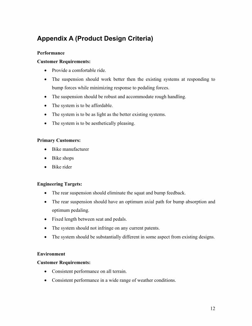
Appendix A (Product Design Criteria) Performance
Customer Requirements:
• Provide a comfortable ride.
• The suspension should work better then the existing systems at responding to
bump forces while minimizing response to pedaling forces.
• The suspension should be robust and accommodate rough handling.
• The system is to be affordable.
• The system is to be as light as the better existing systems.
• The system is to be aesthetically pleasing.
Primary Customers:
• Bike manufacturer
• Bike shops
• Bike rider
Engineering Targets:
• The rear suspension should eliminate the squat and bump feedback.
• The rear suspension should have an optimum axial path for bump absorption and
optimum pedaling.
• Fixed length between seat and pedals.
• The system should not infringe on any current patents.
• The system should be substantially different in some aspect from existing designs.
Environment
Customer Requirements:
• Consistent performance on all terrain.
• Consistent performance in a wide range of weather conditions.

13
Primary Customers: Bike rider
Engineering Targets:
• The suspension will have no adverse environmental effects.
Ergonomics
Customer Requirements:
• The overall weight should be competitive with existing systems.
• The bike should conform to relevant ergonomic standards.
• The system should be able to fit on a wide variety of frame sizes.
Primary Customers: Bike rider
Engineering Targets:
• The system should not change the length between the seat and the pedals.
• The weight of the suspension should be competitive with existing systems.
• The system is to be able to fit riders ranging from 5’ to 6’4” in different frame
sizes.
• The system is to allow the operator to maintain proper ergonomics necessary for
maximum biomechanical advantage.
Safety
Customer Requirements:
• The suspension is to be safe for the rider.
• The system is to fulfill any existing safety regulations.
Primary Customers:
• Bike rider
• Bike mechanic
Engineering Targets:
14
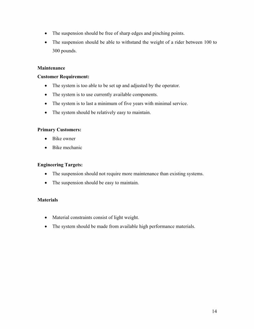
• The suspension should be free of sharp edges and pinching points.
• The suspension should be able to withstand the weight of a rider between 100 to
300 pounds.
Maintenance
Customer Requirement:
• The system is too able to be set up and adjusted by the operator.
• The system is to use currently available components.
• The system is to last a minimum of five years with minimal service.
• The system should be relatively easy to maintain.
Primary Customers:
• Bike owner
• Bike mechanic
Engineering Targets:
• The suspension should not require more maintenance than existing systems.
• The suspension should be easy to maintain.
Materials
• Material constraints consist of light weight.
• The system should be made from available high performance materials.

15
Appendix B (Research Sources)
United States Patents
1. 6,206,397. Bicycle Wheel Travel Path for Selectively Applying Chainstay Lengthening Effect and Apparatus for Providing Same. Klassen et al. 2001.
2. 6,452,910. Rear Wheel Suspension for a Bicycle and Bicycle Equipped Therewith.
Harris, Trevor L. 1995. 3. 6,450,521. Suspension System for a Vehicle. Turner, Paul H. 2002. 4. 6,099,010. Bicycle With Crank Assembly Suspension System. Busby, James S.
2000. 5. 5,899,480. Rear Suspension for Bicycles. Leitner, Horst. 1999. 6. 6,131,934. Bicycle Rear Suspension System. Sinclair, Christopher Jeffery. 2000. 7. 6,386,568. Bicycle Rear Suspension. Tribotte, Pascal. 2002. 8. 5,791,674. Bicycle Suspension System. D’Aluisio et al. 1998. 9. 6,439,593. Rear Shock Absorbing Assembly for a Bicycle. Diing-Huang Tseng.
2002. 10. 6,406,048. Pivotless Rear Suspension System for Bicycles. Castellano, John P.
2002. 11. 5,957,473. Rear Suspension Bicycle. Lawwill, Mert. 1999. 12. 5,921,572. Continuously Compensating Bicycle Suspension System. Bard, Aaron
E. 1999. 13. 6,595,538. Bicycle Suspension Apparatus and Related Method. Ellsworth,
Anthony S. 2003. 14. 5,671,936. Shock Absorbing Bicycle Frame Apparatus. Turner, David Roy.
1997. 15. 6,203,042. Bicycle Rear Suspension System Providing Relative Rearward Motion
of Rear Axle. Wilcox, Weston M. 2001. 16. 6,102,421. Rear Suspension for a Bicycle. Lawwill, Merton R. 2000.

16
17. 5,474,318. Long Travel Rear Suspension System for Bicycles. Castellano, John P. 1995
Web Pages www.specializedbikes.com/sbc4Bar www.giantbicycles.com/us/ www.merida.com/s0_global/main www.ellsworthbikes.com www.santacruzbicycles.com www.kleinbicycles.com www.maverickusa.com www.whytebikes.com/white-2004/quad-link www.bikes.com/tech/tech. www.dwlink.com/technology

17
Appendix C (Concepts)
Figure 1 – Four-Bar System
Figure 2 – Five-Bar System

18
Figure 3 – Swing Arm System
Figure 4 – Flexible Member System
Figure 5 – Motor Drive System.

19
Figure 6 – Flexible Wheel System
Figure 7 – Active Control System
Control Valve Electrical sensor
Shock Absorber

20
Appendix D (Gant Chart)