MOUNT - Unirac Solar PV Racking...Rail Splice 1/2” 10 Anti-Seize STANDARD SYSTEM COMPONENTS A SM...
21
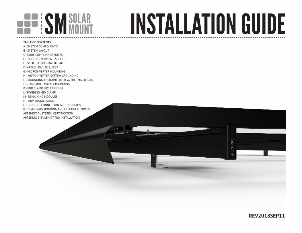
SM SOLAR MOUNT INSTALLATION GUIDE TABLE OF CONTENTS A - SYSTEM COMPONENTS B - SYSTEM LAYOUT C - CODE COMPLIANCE NOTES D - ROOF ATTACHMENT & L-FEET E - SPLICE & THERMAL BREAK F - ATTACH RAIL TO L-FEET G - MICROINVERTER MOUNTING H - MICROINVERTER SYSTEM GROUNDING I - GROUNDING, MICROINVERTER W/THERMAL BREAK J - STANDARD SYSTEM GROUNDING K - END CLAMP, FIRST MODULE L - BONDING MID CLAMP M - REMAINING MODULES N - TRIM INSTALLATION O - BONDING CONNECTION GROUND PATHS P - TEMPORARY BONDING AND ELECTRICAL NOTES APPENDIX A : SYSTEM CERTIFICATION APPENDIX B: FLASHKIT PRO INSTALLATION REV2018SEP11
Transcript of MOUNT - Unirac Solar PV Racking...Rail Splice 1/2” 10 Anti-Seize STANDARD SYSTEM COMPONENTS A SM...
SM SOLARMOUNT INSTALLATION GUIDE
TABLE OF CONTENTSA - SYSTEM COMPONENTSB - SYSTEM LAYOUTC - CODE COMPLIANCE NOTESD - ROOF ATTACHMENT & L-FEETE - SPLICE & THERMAL BREAKF - ATTACH RAIL TO L-FEETG - MICROINVERTER MOUNTINGH - MICROINVERTER SYSTEM GROUNDINGI - GROUNDING, MICROINVERTER W/THERMAL BREAKJ - STANDARD SYSTEM GROUNDINGK - END CLAMP, FIRST MODULEL - BONDING MID CLAMPM - REMAINING MODULESN - TRIM INSTALLATIONO - BONDING CONNECTION GROUND PATHSP - TEMPORARY BONDING AND ELECTRICAL NOTESAPPENDIX A : SYSTEM CERTIFICATIONAPPENDIX B: FLASHKIT PRO INSTALLATION
REV2018SEP11
SM SOLARMOUNT INSTALLATION GUIDE PAGE
Wrench or Socket Size RecommendedTorque (ft-lbs)
Mid Clamp 1/2” 11
MLPE Mount 1/2” 10
End Clamp 1/2” 3
L-Foot to Rail 1/2” 30
Rail Splice 1/2” 10
Anti-Seize
STANDARD SYSTEM COMPONENTS A
SM LIGHT RAIL
SM STANDARD RAIL
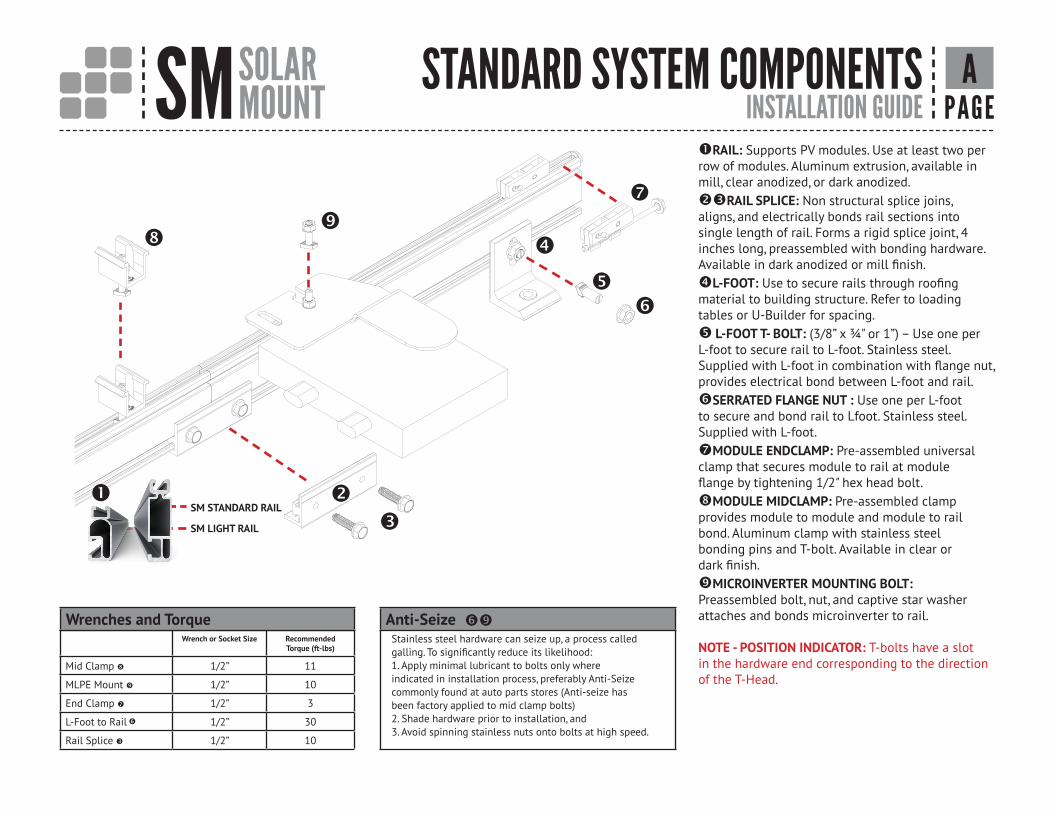
RAIL: Supports PV modules. Use at least two perrow of modules. Aluminum extrusion, available inmill, clear anodized, or dark anodized.RAIL SPLICE: Non structural splice joins, aligns, and electrically bonds rail sections into single length of rail. Forms a rigid splice joint, 4 inches long, preassembled with bonding hardware. Available in dark anodized or mill finish.L-FOOT: Use to secure rails through roofingmaterial to building structure. Refer to loading tables or U-Builder for spacing. L-FOOT T- BOLT: (3/8” x ¾" or 1”) – Use one perL-foot to secure rail to L-foot. Stainless steel.Supplied with L-foot in combination with flange nut,provides electrical bond between L-foot and rail.SERRATED FLANGE NUT : Use one per L-foot to secure and bond rail to Lfoot. Stainless steel. Supplied with L-foot.MODULE ENDCLAMP: Pre-assembled universalclamp that secures module to rail at moduleflange by tightening 1/2" hex head bolt.MODULE MIDCLAMP: Pre-assembled clampprovides module to module and module to railbond. Aluminum clamp with stainless steelbonding pins and T-bolt. Available in clear ordark finish.MICROINVERTER MOUNTING BOLT: Preassembled bolt, nut, and captive star washerattaches and bonds microinverter to rail.
NOTE - POSITION INDICATOR: T-bolts have a slotin the hardware end corresponding to the directionof the T-Head.
Wrenches and Torque
Stainless steel hardware can seize up, a process called galling. To significantly reduce its likelihood:1. Apply minimal lubricant to bolts only whereindicated in installation process, preferably Anti-Seize commonly found at auto parts stores (Anti-seize has been factory applied to mid clamp bolts)2. Shade hardware prior to installation, and3. Avoid spinning stainless nuts onto bolts at high speed.
SM SOLARMOUNT INSTALLATION GUIDE PAGE
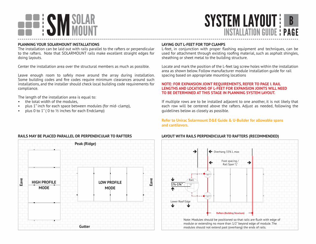
PLANNING YOUR SOLARMOUNT INSTALLATIONSThe installation can be laid out with rails parallel to the rafters or perpendicular to the rafters. Note that SOLARMOUNT rails make excellent straight edges for doing layouts.
Center the installation area over the structural members as much as possible.
Leave enough room to safely move around the array during installation. Some building codes and fire codes require minimum clearances around such installations, and the installer should check local building code requirements for compliance.
The length of the installation area is equal to:• the total width of the modules,• plus 1” inch for each space between modules (for mid- clamp),• plus 0 to 1" ( 0 to ½ inches for each Endclamp)
LAYING OUT L-FEET FOR TOP CLAMPSL-feet, in conjunction with proper flashing equipment and techniques, can be used for attachment through existing roofing material, such as asphalt shingles, sheathing or sheet metal to the building structure.
Locate and mark the position of the L-feet lag screw holes within the installation area as shown below. Follow manufacturer module installation guide for railspacing based on appropriate mounting locations
NOTE: FOR EXPANSION JOINT REQUIREMENTS, REFER TO PAGE I. RAILLENGTHS AND LOCATIONS OF L-FEET FOR EXPANSION JOINTS WILL NEEDTO BE DETERMINED AT THIS STAGE IN PLANNING SYSTEM LAYOUT.
If multiple rows are to be installed adjacent to one another, it is not likely that each row will be centered above the rafters. Adjust as needed, following the guidelines below as closely as possible.
Refer to Unirac Solarmount D&E Guide & U-Builder for allowable spans and cantilevers.
Peak (Ridge)
Eave
Gutter
LOW PROFILE MODE
HIGH PROFILEMODE
1½-1¾”
Foot spacing /Rail Span “L”
Rafters (Building Structure)
Note: Modules should be positioned so that rails are flush with edge of module or extending no more than 1/2" beyond edge of module. The modules should not extend past (overhang) the ends of rails.
SYSTEM LAYOUT
RAILS MAY BE PLACED PARALLEL OR PERPENDICULAR TO RAFTERS LAYOUT WITH RAILS PERPENDICULAR TO RAFTERS (RECOMMENDED)
Eave
Overhang 33% L max
• •
Lower Roof Edge
•
•Rail
B
SM SOLARMOUNT INSTALLATION GUIDE PAGE
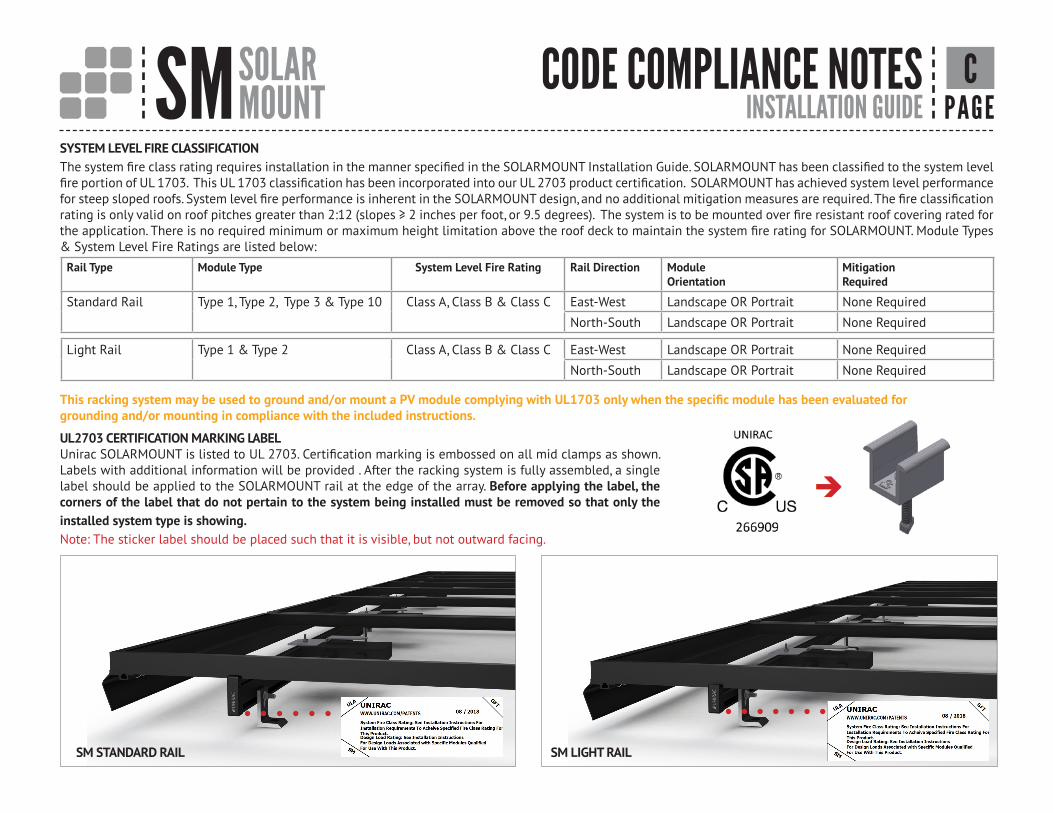
SYSTEM LEVEL FIRE CLASSIFICATIONThe system fire class rating requires installation in the manner specified in the SOLARMOUNT Installation Guide. SOLARMOUNT has been classified to the system level fire portion of UL 1703. This UL 1703 classification has been incorporated into our UL 2703 product certification. SOLARMOUNT has achieved system level performance for steep sloped roofs. System level fire performance is inherent in the SOLARMOUNT design, and no additional mitigation measures are required. The fire classification rating is only valid on roof pitches greater than 2:12 (slopes ≥ 2 inches per foot, or 9.5 degrees). The system is to be mounted over fire resistant roof covering rated for the application. There is no required minimum or maximum height limitation above the roof deck to maintain the system fire rating for SOLARMOUNT. Module Types & System Level Fire Ratings are listed below:
UL2703 CERTIFICATION MARKING LABELUnirac SOLARMOUNT is listed to UL 2703. Certification marking is embossed on all mid clamps as shown. Labels with additional information will be provided . After the racking system is fully assembled, a single label should be applied to the SOLARMOUNT rail at the edge of the array. Before applying the label, the corners of the label that do not pertain to the system being installed must be removed so that only the installed system type is showing.Note: The sticker label should be placed such that it is visible, but not outward facing.
SM STANDARD RAIL SM LIGHT RAIL
CODE COMPLIANCE NOTES
Rail Type Module Type System Level Fire Rating Rail Direction Module Orientation
MitigationRequired
Standard Rail Type 1, Type 2, Type 3 & Type 10 Class A, Class B & Class C East-West Landscape OR Portrait None Required
North-South Landscape OR Portrait None Required
Light Rail Type 1 & Type 2 Class A, Class B & Class C East-West Landscape OR Portrait None Required
North-South Landscape OR Portrait None Required
C
This racking system may be used to ground and/or mount a PV module complying with UL1703 only when the specific module has been evaluated forgrounding and/or mounting in compliance with the included instructions.
SM SOLARMOUNT INSTALLATION GUIDE PAGE
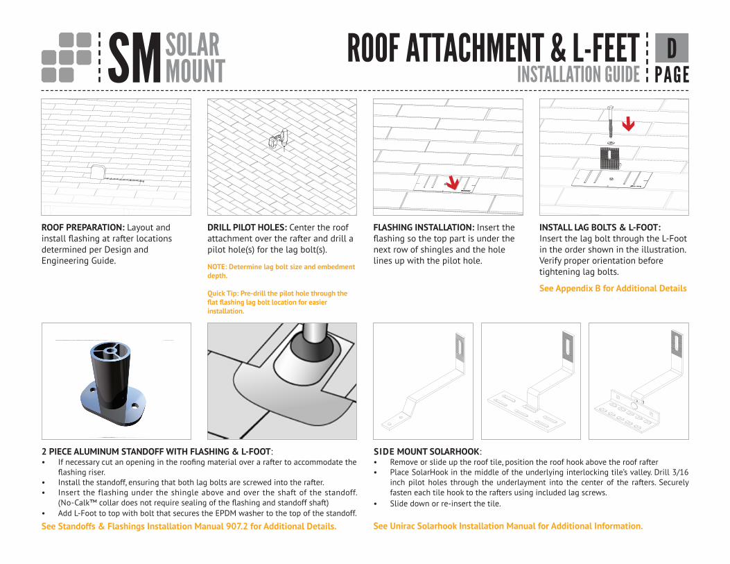
2 PIECE ALUMINUM STANDOFF WITH FLASHING & L-FOOT: • If necessary cut an opening in the roofing material over a rafter to accommodate the
flashing riser. • Install the standoff, ensuring that both lag bolts are screwed into the rafter. • Insert the flashing under the shingle above and over the shaft of the standoff.
(No-Calk™ collar does not require sealing of the flashing and standoff shaft) • Add L-Foot to top with bolt that secures the EPDM washer to the top of the standoff.
See Standoffs & Flashings Installation Manual 907.2 for Additional Details.
DRILL PILOT HOLES: Center the roof attachment over the rafter and drill a pilot hole(s) for the lag bolt(s).
NOTE: Determine lag bolt size and embedment depth.
Quick Tip: Pre-drill the pilot hole through the flat flashing lag bolt location for easier installation.
FLASHING INSTALLATION: Insert the flashing so the top part is under the next row of shingles and the hole lines up with the pilot hole.
INSTALL LAG BOLTS & L-FOOT:Insert the lag bolt through the L-Foot in the order shown in the illustration.Verify proper orientation before tightening lag bolts.
See Appendix B for Additional Details
ROOF ATTACHMENT & L-FEET
ROOF PREPARATION: Layout and install flashing at rafter locations determined per Design and Engineering Guide.
SIDE MOUNT SOLARHOOK: • Remove or slide up the roof tile, position the roof hook above the roof rafter• Place SolarHook in the middle of the underlying interlocking tile’s valley. Drill 3/16
inch pilot holes through the underlayment into the center of the rafters. Securely fasten each tile hook to the rafters using included lag screws.
• Slide down or re-insert the tile.
D
See Unirac Solarhook Installation Manual for Additional Information.
SM SOLARMOUNT INSTALLATION GUIDE PAGE
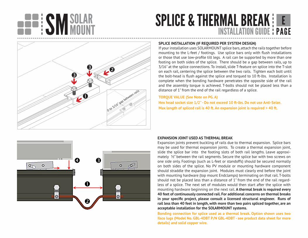
SPLICE INSTALLATION (IF REQUIRED PER SYSTEM DESIGN)If your installation uses SOLARMOUNT splice bars, attach the rails together before mounting to the L-feet / footings. Use splice bars only with flush installations or those that use low-profile tilt legs. A rail can be supported by more than one footing on both sides of the splice. There should be a gap between rails, up to 3/16" at the splice connections. To install, slide T-feature on splice into the T-slot on each rail, centering the splice between the two rails. Tighten each bolt until the bolt-head is flush against the splice and torqued to 10 ft-lbs. Installation is complete when the bonding hardware penetrates the opposite side of the rail and the assembly torque is achieved. T-bolts should not be placed less than a distance of 1" from the end of the rail regardless of a splice.
TORQUE VALUE (See Note on PG. A)Hex head socket size 1/2" - Do not exceed 10 ft-lbs. Do not use Anti-Seize.Max length of spliced rail is 40 ft. An expansion joint is required > 40 ft.
0 to 3/16” gap between rails
SPLICE & THERMAL BREAK
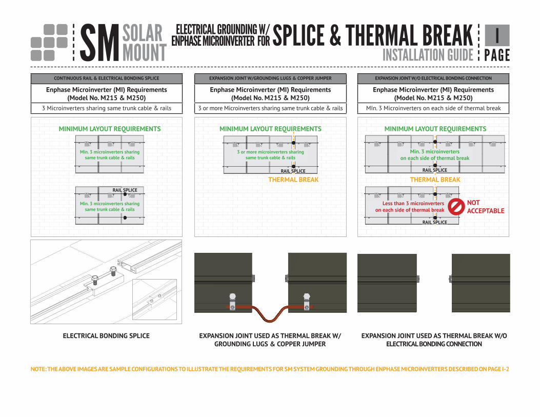
EXPANSION JOINT USED AS THERMAL BREAKExpansion joints prevent buckling of rails due to thermal expansion. Splice bars may be used for thermal expansion joints. To create a thermal expansion joint, slide the splice bar into the footing slots of both rail lengths. Leave approxi-mately ½” between the rail segments. Secure the splice bar with two screws on one side only. Footings (such as L-feet or standoffs) should be secured normally on both sides of the splice. No PV module or mounting hardware component should straddle the expansion joint. Modules must clearly end before the joint with mounting hardware (top mount Endclamps) terminating on that rail. T-bolts should not be placed less than a distance of 1" from the end of the rail regard-less of a splice. The next set of modules would then start after the splice with mounting hardware beginning on the next rail. A thermal break is required every 40 feet of continuously connected rail. For additional concerns on thermal breaks in your specific project, please consult a licensed structural engineer. Runs of rail less than 40 feet in length, with more than two pairs spliced together, are an acceptable installation for the SOLARMOUNT systems. Bonding connection for splice used as a thermal break. Option shown uses two Ilsco lugs (Model No. GBL-4DBT P/N GBL-4DBT - see product data sheet for more details) and solid copper wire.
E
�
�
� �
SM SOLARMOUNT INSTALLATION GUIDE PAGE
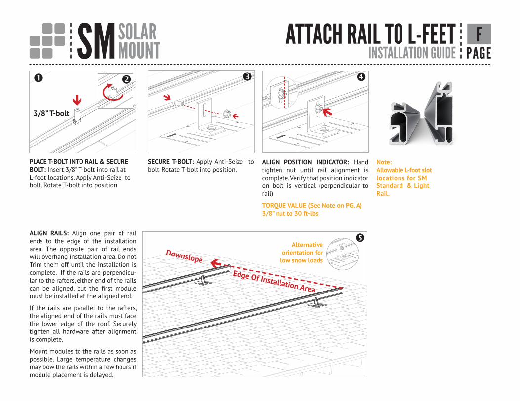
Note:Allowable L-foot slot locations for SM Standard & Light Rail.
3/8” T-bolt
PLACE T-BOLT INTO RAIL & SECURE BOLT: Insert 3/8” T-bolt into rail at L-foot locations. Apply Anti-Seize to bolt. Rotate T-bolt into position.
ATTACH RAIL TO L-FEET
ALIGN POSITION INDICATOR: Hand tighten nut until rail alignment is complete. Verify that position indicator on bolt is vertical (perpendicular to rail)
TORQUE VALUE (See Note on PG. A)3/8” nut to 30 ft-lbs
ALIGN RAILS: Align one pair of rail ends to the edge of the installation area. The opposite pair of rail ends will overhang installation area. Do not Trim them off until the installation is complete. If the rails are perpendicu-lar to the rafters, either end of the rails can be aligned, but the first module must be installed at the aligned end.
If the rails are parallel to the rafters, the aligned end of the rails must face the lower edge of the roof. Securely tighten all hardware after alignment is complete.
Mount modules to the rails as soon as possible. Large temperature changes may bow the rails within a few hours if module placement is delayed.
Edge Of Installation Area
Downslope
SECURE T-BOLT: Apply Anti-Seize to bolt. Rotate T-bolt into position.
F
Alternative orientation for
low snow loads
SM SOLARMOUNT INSTALLATION GUIDE PAGE
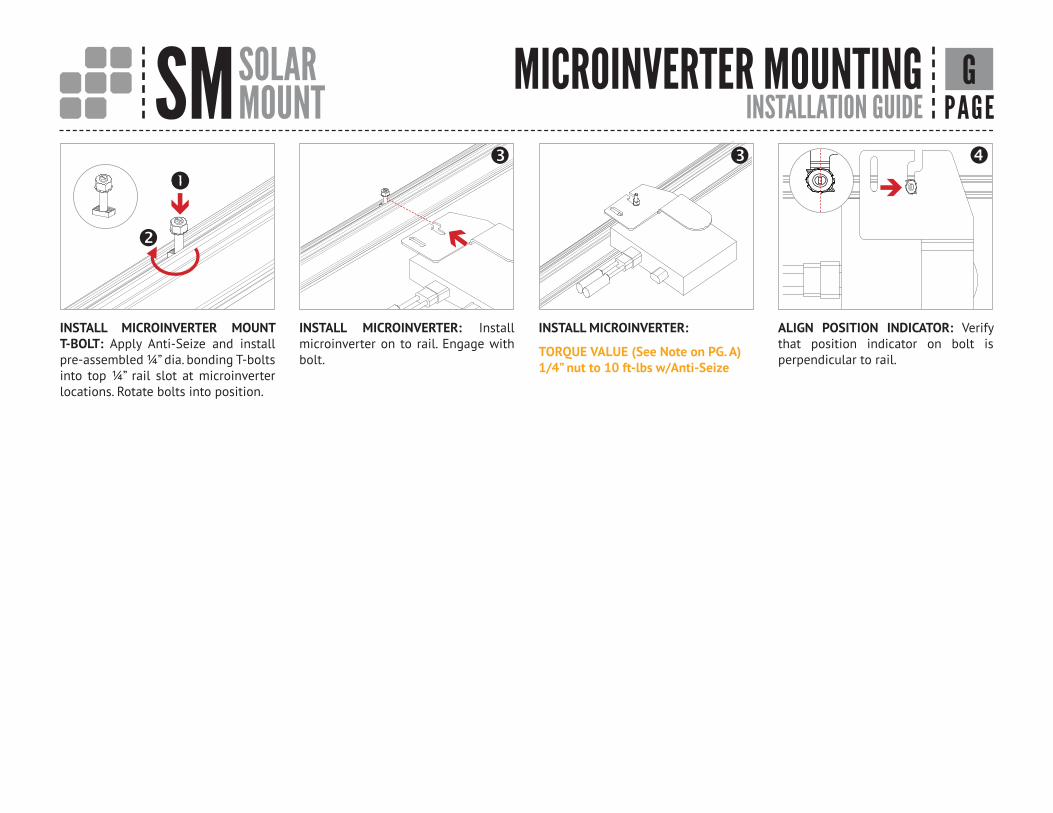
INSTALL MICROINVERTER MOUNT T-BOLT: Apply Anti-Seize and install pre-assembled ¼” dia. bonding T-bolts into top ¼” rail slot at microinverter locations. Rotate bolts into position.
INSTALL MICROINVERTER: Install microinverter on to rail. Engage with bolt.
INSTALL MICROINVERTER:
TORQUE VALUE (See Note on PG. A)1/4” nut to 10 ft-lbs w/Anti-Seize
ALIGN POSITION INDICATOR: Verify that position indicator on bolt is perpendicular to rail.
MICROINVERTER MOUNTING
G

SM SOLARMOUNT INSTALLATION GUIDE PAGE
MICROINVERTER SYSTEM GROUNDING SM EQUIPMENT GROUNDING THROUGH ENPHASE MICROINVERTERSThe Enphase M215 and M250 microinverters have integrated grounding capabilities built in. In this case, the DC circuit is isolated from the AC circuit, and the AC equipment grounding conductor (EGC) is built into the Enphase Engage integrated grounding (IG) cabling.In order to ground the SOLARMOUNT racking system through the Enphase microinverter and Engage cable assembly, there must be a minimum of three PV modules connected to the same trunk cable within a continuous row. Continuous row is defined as a grouping of modules installed and bonded per the requirements of this installation guide sharing the same two rails. The microinverters are bonded to the SOLARMOUNT rail via the mounting hardware. Complete equipment grounding is achieved through the Enphase Engage cabling with integrated grounding (IG). No additional EGC grounding cables are required, as all fault current is carried to ground through the Engage cable.
SOLARMOUNT INTEGRATED BONDING ADVANTAGEWITH SYSTEM GROUNDING THROUGH ENPHASE MICROINVERTERS AND TRUNK CABLES
LOSE ALL THE COPPER & LUGS
H
SM SOLARMOUNT INSTALLATION GUIDE PAGE
SPLICE & THERMAL BREAK
NOTE: THE ABOVE IMAGES ARE SAMPLE CONFIGURATIONS TO ILLUSTRATE THE REQUIREMENTS FOR SM SYSTEM GROUNDING THROUGH ENPHASE MICROINVERTERS DESCRIBED ON PAGE I-2
CONTINUOUS RAIL & ELECTRICAL BONDING SPLICE
Enphase Microinverter (MI) Requirements(Model No. M215 & M250)
3 Microinverters sharing same trunk cable & rails
EXPANSION JOINT W/GROUNDING LUGS & COPPER JUMPER
Enphase Microinverter (MI) Requirements(Model No. M215 & M250)
3 or more Microinverters sharing same trunk cable & rails
EXPANSION JOINT W/O ELECTRICAL BONDING CONNECTION
Enphase Microinverter (MI) Requirements(Model No. M215 & M250)
MIn. 3 Microinverters on each side of thermal break
THERMAL BREAK
Min. 3 microinverterson each side of thermal break
Min. 3 microinverters sharing same trunk cable & rails
Min. 3 microinverters sharing same trunk cable & rails
Less than 3 microinverterson each side of thermal break
RAIL SPLICE
RAIL SPLICE
RAIL SPLICE
RAIL SPLICE
NOT ACCEPTABLE
MINIMUM LAYOUT REQUIREMENTSMINIMUM LAYOUT REQUIREMENTSMINIMUM LAYOUT REQUIREMENTS
ELECTRICAL GROUNDING W/ENPHASE MICROINVERTER FOR
ELECTRICAL BONDING SPLICE EXPANSION JOINT USED AS THERMAL BREAK W/ GROUNDING LUGS & COPPER JUMPER
EXPANSION JOINT USED AS THERMAL BREAK W/O ELECTRICAL BONDING CONNECTION
THERMAL BREAK
3 or more microinverters sharing same trunk cable & rails
I
SM SOLARMOUNT INSTALLATION GUIDE PAGE
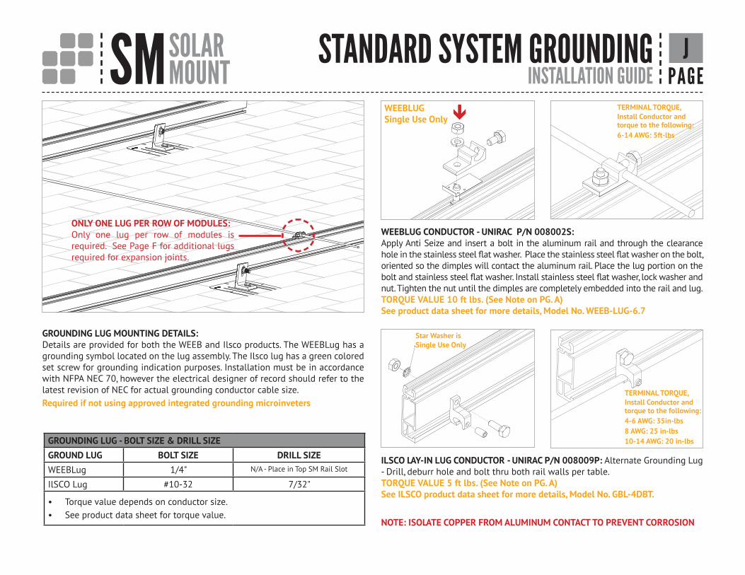
GROUNDING LUG MOUNTING DETAILS:Details are provided for both the WEEB and Ilsco products. The WEEBLug has a grounding symbol located on the lug assembly. The Ilsco lug has a green colored set screw for grounding indication purposes. Installation must be in accordance with NFPA NEC 70, however the electrical designer of record should refer to the latest revision of NEC for actual grounding conductor cable size.Required if not using approved integrated grounding microinveters
WEEBLUG CONDUCTOR - UNIRAC P/N 008002S:Apply Anti Seize and insert a bolt in the aluminum rail and through the clearance hole in the stainless steel flat washer. Place the stainless steel flat washer on the bolt, oriented so the dimples will contact the aluminum rail. Place the lug portion on the bolt and stainless steel flat washer. Install stainless steel flat washer, lock washer and nut. Tighten the nut until the dimples are completely embedded into the rail and lug.TORQUE VALUE 10 ft lbs. (See Note on PG. A)See product data sheet for more details, Model No. WEEB-LUG-6.7
ILSCO LAY-IN LUG CONDUCTOR - UNIRAC P/N 008009P: Alternate Grounding Lug - Drill, deburr hole and bolt thru both rail walls per table. TORQUE VALUE 5 ft lbs. (See Note on PG. A)See ILSCO product data sheet for more details, Model No. GBL-4DBT.
NOTE: ISOLATE COPPER FROM ALUMINUM CONTACT TO PREVENT CORROSION
GROUNDING LUG - BOLT SIZE & DRILL SIZEGROUND LUG BOLT SIZE DRILL SIZEWEEBLug 1/4" N/A - Place in Top SM Rail Slot
IlSCO Lug #10-32 7/32"
• Torque value depends on conductor size.• See product data sheet for torque value.
STANDARD SYSTEM GROUNDING J
ONLY ONE LUG PER ROW OF MODULES:Only one lug per row of modules is required. See Page F for additional lugs required for expansion joints.
TERMINAL TORQUE, Install Conductor and torque to the following: 4-6 AWG: 35in-lbs8 AWG: 25 in-lbs10-14 AWG: 20 in-lbs
Star Washer isSingle Use Only
WEEBLUGSingle Use Only
TERMINAL TORQUE,Install Conductor and torque to the following: 6-14 AWG: 5ft-lbs
SM SOLARMOUNT INSTALLATION GUIDE PAGE
ENDCLAMP, FIRST MODULE &TRIM K
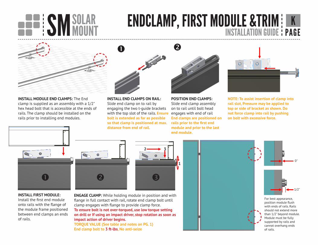
INSTALL MODULE END CLAMPS: The Endclamp is supplied as an assembly with a 1/2"hex head bolt that is accessible at the ends ofrails. The clamp should be installed on therails prior to installing end modules.
INSTALL END CLAMPS ON RAIL:Slide end clamp on to rail byengaging the two t-guide brackets with the top slot of the rails. Ensure bolt is extended as far as possible so that clamp is positioned at max.distance from end of rail.
POSITION END CLAMPS:Slide end clamp assemblyon to rail until bolt headengages with end of railEnd clamps are positioned onrails prior to the first endmodule and prior to the lastend module.
NOTE: To assist insertion of clamp intorail slot, Pressure may be applied totop or side of bracket as shown. Donot force clamp into rail by pushingon bolt with excessive force.
INSTALL FIRST MODULE: Install the first end module onto rails with the flange of the module frame positionedbetween end clamps an ends of rails.
ENGAGE CLAMP: While holding module in position and with flange in full contact with rail, rotate end clamp bolt until clamp engages with flange to provide clamp force.To ensure bolt is not over-torqued, use low torque setting on drill or If using an impact driver, stop rotation as soon as impact action of driver begins.TORQUE VALUE (See table and notes on PG. 1)End clamp bolt to 3 ft-lbs, No anti-seize
For best appearance, position module flush with ends of rails. Rails should not extend more than 1/2" beyond module. Module must be fullysupported by rails and cannot overhang ends of rails.
1
2 3
1/2"
0"
SM SOLARMOUNT INSTALLATION GUIDE PAGE
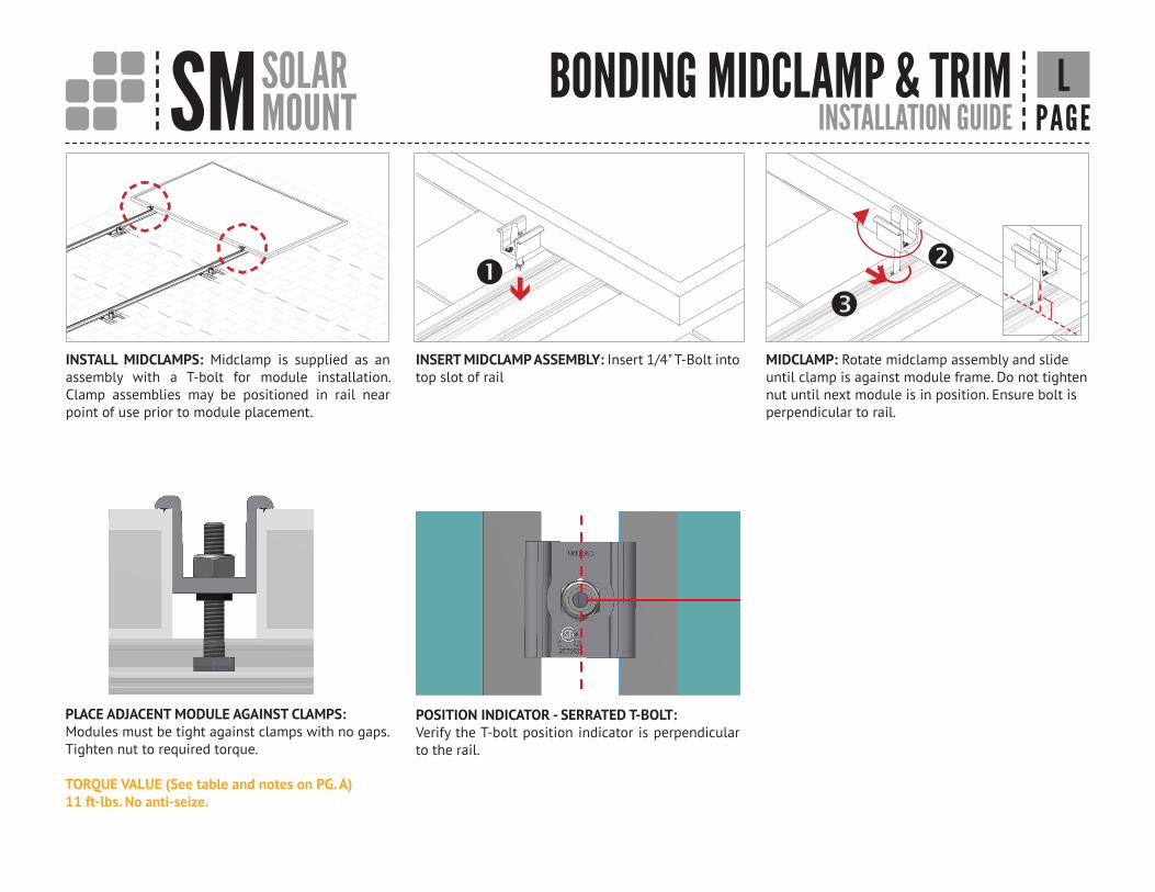
MIDCLAMP: Rotate midclamp assembly and slide until clamp is against module frame. Do not tighten nut until next module is in position. Ensure bolt is perpendicular to rail.
INSERT MIDCLAMP ASSEMBLY: Insert 1/4" T-Bolt into top slot of rail
INSTALL MIDCLAMPS: Midclamp is supplied as an assembly with a T-bolt for module installation. Clamp assemblies may be positioned in rail near point of use prior to module placement.
BONDING MIDCLAMP & TRIM L
PLACE ADJACENT MODULE AGAINST CLAMPS:Modules must be tight against clamps with no gaps.Tighten nut to required torque.
TORQUE VALUE (See table and notes on PG. A)11 ft-lbs. No anti-seize.
POSITION INDICATOR - SERRATED T-BOLT: Verify the T-bolt position indicator is perpendicular to the rail.
SM SOLARMOUNT INSTALLATION GUIDE PAGE
REMAINING MODULES M
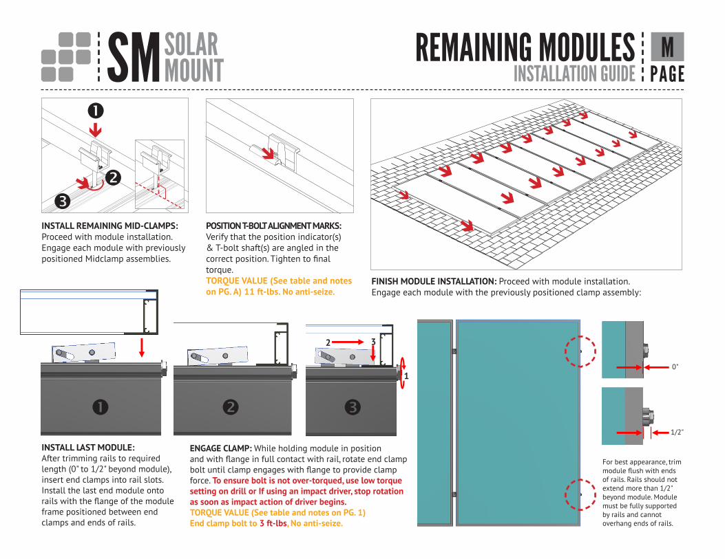
INSTALL REMAINING MID-CLAMPS: Proceed with module installation. Engage each module with previously positioned Midclamp assemblies.
FINISH MODULE INSTALLATION: Proceed with module installation. Engage each module with the previously positioned clamp assembly:
POSITION T-BOLT ALIGNMENT MARKS:Verify that the position indicator(s) & T-bolt shaft(s) are angled in the correct position. Tighten to final torque.TORQUE VALUE (See table and noteson PG. A) 11 ft-lbs. No anti-seize.
INSTALL LAST MODULE: After trimming rails to required length (0" to 1/2" beyond module), insert end clamps into rail slots. Install the last end module onto rails with the flange of the module frame positioned between end clamps and ends of rails.
ENGAGE CLAMP: While holding module in positionand with flange in full contact with rail, rotate end clamp bolt until clamp engages with flange to provide clamp force. To ensure bolt is not over-torqued, use low torque setting on drill or If using an impact driver, stop rotation as soon as impact action of driver begins.TORQUE VALUE (See table and notes on PG. 1)End clamp bolt to 3 ft-lbs, No anti-seize.
For best appearance, trim module flush with ends of rails. Rails should not extend more than 1/2"beyond module. Module must be fully supported by rails and cannot overhang ends of rails.
1
2 3
1/2"
0"
SM SOLARMOUNT INSTALLATION GUIDE PAGE
NTRIM AND END CAP INSTALLATION
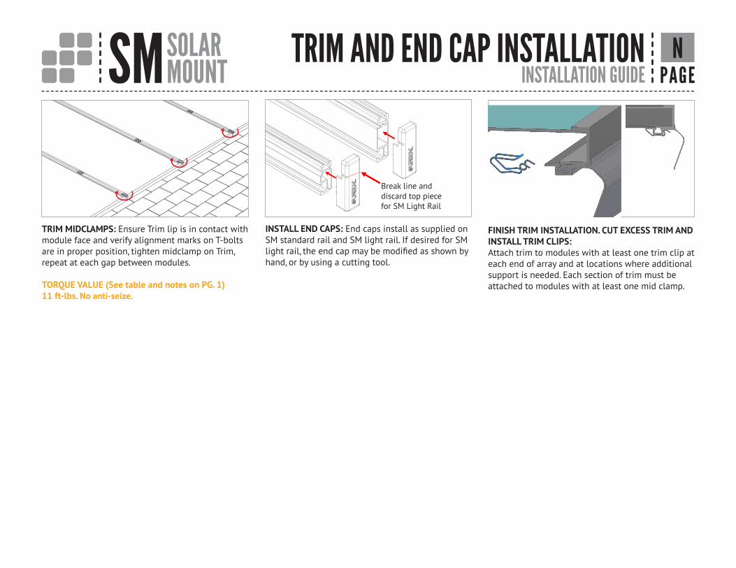
TRIM MIDCLAMPS: Ensure Trim lip is in contact with module face and verify alignment marks on T-bolts are in proper position, tighten midclamp on Trim, repeat at each gap between modules.
TORQUE VALUE (See table and notes on PG. 1) 11 ft-lbs. No anti-seize.
INSTALL END CAPS: End caps install as supplied on SM standard rail and SM light rail. If desired for SM light rail, the end cap may be modified as shown by hand, or by using a cutting tool.
Break line and discard top piece for SM Light Rail
FINISH TRIM INSTALLATION. CUT EXCESS TRIM AND INSTALL TRIM CLIPS: Attach trim to modules with at least one trim clip at each end of array and at locations where additional support is needed. Each section of trim must be attached to modules with at least one mid clamp.
SM SOLARMOUNT INSTALLATION GUIDE PAGE
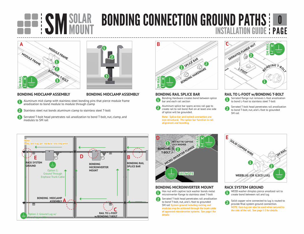
Aluminum mid clamp with stainless steel bonding pins that pierce module frame anodization to bond module to module through clamp
Stainless steel nut bonds aluminum clamp to stainless steel T-bolt
Serrated T-bolt head penetrates rail anodization to bond T-bolt, nut, clamp, and modules to SM rail
BONDING MIDCLAMP ASSEMBLY BONDING MIDCLAMP ASSEMBLY BONDING RAIL SPLICE BAR
BONDING MICROINVERTER MOUNT
RAIL TO L-FOOT w/BONDING T-BOLT
RAIL TO L-FOOT w/BONDING T-BOLT
BONDING RAILSPLICE BAR
RACK SYSTEM GROUND
MODULE FRAME
BONDING CONNECTION GROUND PATHS O
Bonding Hardware creates bond between splice bar and each rail section
Aluminum splice bar spans across rail gap to create rail to rail bond. Rail on at least one side of splice will be grounded.
Note: Splice bar and bolted connection are non-structural. The splice bar function is rail alignment and bonding.
Serrated flange nut removes L-foot anodization to bond L-Foot to stainless steel T-bolt
Serrated T-bolt head penetrates rail anodization to bond T-bolt, nut, and L-foot to grounded SM rail
Hex nut with captive lock washer bonds metal microinverter flange to stainless steel T-bolt
Serrated T-bolt head penetrates rail anodization to bond T-bolt, nut, and L-foot to grounded SM rail System ground including racking and modules may be achieved through the trunk cable of approved microinverter systems. See page I for details
WEEB washer dimples pierce anodized rail to create bond between rail and lug
Solid copper wire connected to lug is routed to provide final system ground connection.NOTE: Ilsco lug can also be used when secured to the side of the rail. See page I-3 for details
WEEBLUG (OR ILSCO LUG)
SM R
AIL
SM R
AIL
SM R
AIL
SM R
AIL
MODULE FRAME
BONDING T-BOLT
2
2
2
2
2
2
2
2 2
22
1
1
1
1
1
1
1 1
11
3
3 BONDING HARDWARESPLICE BAR
SM RAIL
MICRO-INVERTER FLANGE
SERRATED FLANGE NUT
L-FOOT BONDING T-BOLT
1
SEE NOTE
HEX NUT W/ CAPTIVE LOCK WASHER
BONDINGT-BOLT
SOLID COPPER WIRE
BONDING MICROINVERTER MOUNT
BONDING MIDCLAMP ASSEMBLY
RACK SYSTEM GROUND
Note: Only one lug per module row required
3
A B C
D E
B
A
C
DE
Option 1:Ground Through
Enphase Trunk Cable
Option 2: Ground Lug w/Bare Copper Wire
SM SOLARMOUNT INSTALLATION GUIDE PAGE
BONDING CONNECTION GROUND PATHS P
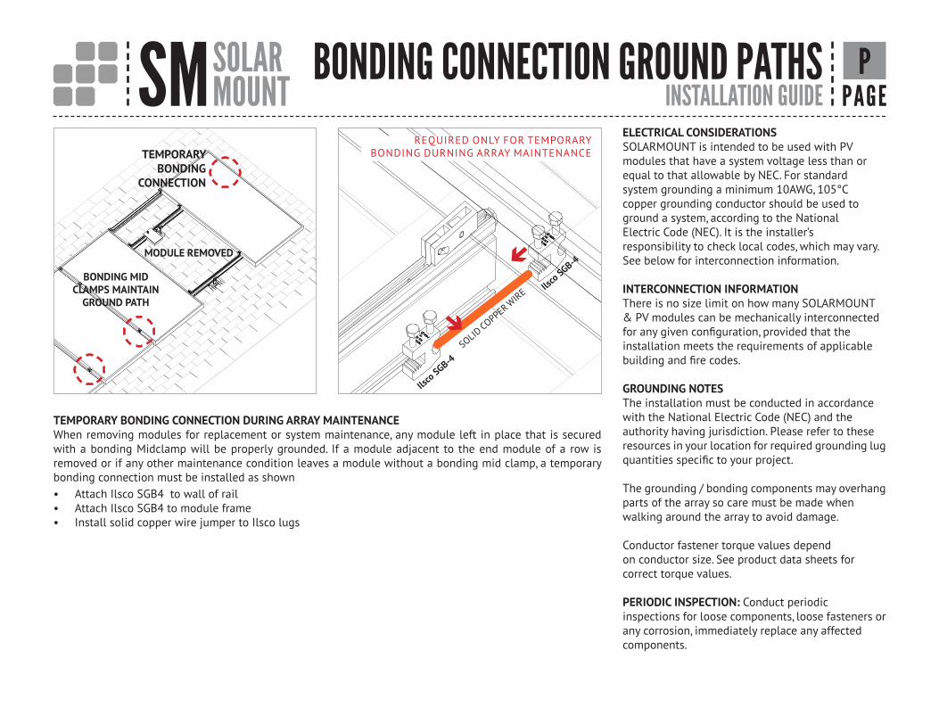
TEMPORARY BONDING CONNECTION DURING ARRAY MAINTENANCEWhen removing modules for replacement or system maintenance, any module left in place that is secured with a bonding Midclamp will be properly grounded. If a module adjacent to the end module of a row is removed or if any other maintenance condition leaves a module without a bonding mid clamp, a temporary bonding connection must be installed as shown• Attach Ilsco SGB4 to wall of rail• Attach Ilsco SGB4 to module frame• Install solid copper wire jumper to Ilsco lugs
MODULE REMOVED
BONDING MID CLAMPS MAINTAIN
GROUND PATH
TEMPORARYBONDING
CONNECTION
ELECTRICAL CONSIDERATIONSSOLARMOUNT is intended to be used with PVmodules that have a system voltage less than orequal to that allowable by NEC. For standardsystem grounding a minimum 10AWG, 105°Ccopper grounding conductor should be used toground a system, according to the NationalElectric Code (NEC). It is the installer’sresponsibility to check local codes, which may vary.See below for interconnection information.
INTERCONNECTION INFORMATIONThere is no size limit on how many SOLARMOUNT& PV modules can be mechanically interconnectedfor any given configuration, provided that theinstallation meets the requirements of applicablebuilding and fire codes.
GROUNDING NOTESThe installation must be conducted in accordancewith the National Electric Code (NEC) and theauthority having jurisdiction. Please refer to theseresources in your location for required grounding lugquantities specific to your project.
The grounding / bonding components may overhangparts of the array so care must be made whenwalking around the array to avoid damage.
Conductor fastener torque values dependon conductor size. See product data sheets forcorrect torque values.
PERIODIC INSPECTION: Conduct periodicinspections for loose components, loose fasteners orany corrosion, immediately replace any affectedcomponents.
Ilsco SGB-4
SOLID COPPER W
IRE Ilsco SGB-4
REQUIRED ONLY FOR TEMPORARY BONDING DURNING ARRAY MAINTENANCE
SM SOLARMOUNT System Certification PAGE
APPENDIX A Q
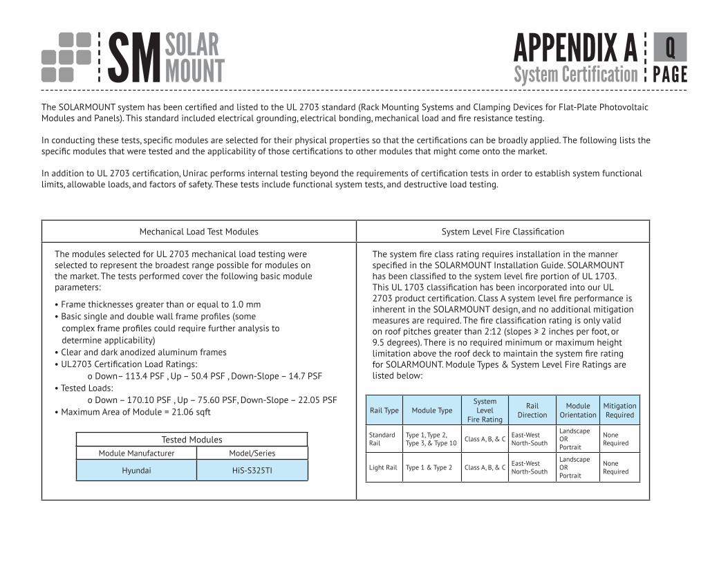
The SOLARMOUNT system has been certified and listed to the UL 2703 standard (Rack Mounting Systems and Clamping Devices for Flat-Plate Photovoltaic Modules and Panels). This standard included electrical grounding, electrical bonding, mechanical load and fire resistance testing.
In conducting these tests, specific modules are selected for their physical properties so that the certifications can be broadly applied. The following lists the specific modules that were tested and the applicability of those certifications to other modules that might come onto the market.
In addition to UL 2703 certification, Unirac performs internal testing beyond the requirements of certification tests in order to establish system functional limits, allowable loads, and factors of safety. These tests include functional system tests, and destructive load testing.
Mechanical Load Test Modules System Level Fire Classification
The modules selected for UL 2703 mechanical load testing were selected to represent the broadest range possible for modules on the market. The tests performed cover the following basic module parameters:
The system fire class rating requires installation in the manner specified in the SOLARMOUNT Installation Guide. SOLARMOUNT has been classified to the system level fire portion of UL 1703. This UL 1703 classification has been incorporated into our UL2703 product certification. Class A system level fire performance is inherent in the SOLARMOUNT design, and no additional mitigation measures are required. The fire classification rating is only valid on roof pitches greater than 2:12 (slopes ≥ 2 inches per foot, or 9.5 degrees). There is no required minimum or maximum height limitation above the roof deck to maintain the system fire rating for SOLARMOUNT. Module Types & System Level Fire Ratings are listed below:
• Frame thicknesses greater than or equal to 1.0 mm• Basic single and double wall frame profiles (some complex frame profiles could require further analysis to determine applicability)• Clear and dark anodized aluminum frames• UL2703 Certification Load Ratings: o Down– 113.4 PSF , Up – 50.4 PSF , Down-Slope – 14.7 PSF• Tested Loads: o Down – 170.10 PSF , Up – 75.60 PSF, Down-Slope – 22.05 PSF• Maximum Area of Module = 21.06 sqft
Module Manufacturer Model/Series
Hyundai HiS-S325TI
Rail Type Module TypeSystem Level
Fire Rating
RailDirection
ModuleOrientation
MitigationRequired
StandardRail
Type 1, Type 2,Type 3, & Type 10 Class A, B, & C East-West
North-South
Landscape ORPortrait
None Required
Light Rail Type 1 & Type 2 Class A, B, & C East-WestNorth-South
Landscape ORPortrait
None Required
Tested Modules
SM SOLARMOUNT System Certification PAGE
APPENDIX A R
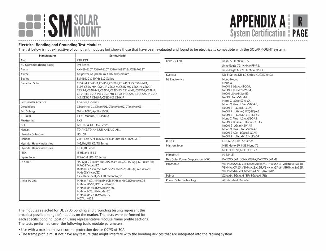
• Use with a maximum over current protection device OCPD of 30A• The frame profile must not have any feature that might interfere with the bonding devices that are integrated into the racking system
The modules selected for UL 2703 bonding and grounding testing represent the broadest possible range of modules on the market. The tests were performed for each specific bonding location using representative module frame profile sections. The tests performed cover the following basic module parameters:
Electrical Bonding and Grounding Test ModulesThe list below is not exhaustive of compliant modules but shows those that have been evaluated and found to be electrically compatible with the SOLARMOUNT system.
Manufacturer Series/ModelAleo P18, P19
AU Optronics (BenQ Solar) PM Series
Auxin AXN6M610T, AXN6P610T, AXN6M612T & AXN6P612T
Axitec AXIpower, AXIpremium, AXIblackpremium
Boviet BVM6610 & BVM6612 Series
Canadian Solar CS5A-M, CS6P-M, CS6P-P, CS6X-P, CSX-P, ELPS CS6P-MM, ELPS CS6A-MM, CS6U-P, CS6U-M, CS6K-MS, CS6K-M, CS6K-P, CS3U-P, CS3U-MS, CS3K-P, CS3K-MS, CS1K-MS, CS3W-P, CS3L-P, CS3K-MB, CS3K-PB, CS3U-MB, CS3U-PB, CS3U-MS, CS3U-P, CS3K-MS, CS3K-P, CS6U-P, CS6K-MS, CS6K-P
Centrosolar America C-Series, E-Series
CertainTeed CTxxxMxx-01, CTxxxP01, CTxxxMxx02, CTxxxMxx03
Eco Solargy Orion 1000, Apollo 1000
ET Solar ET AC Module, ET Module
Flextronics FXS
GCL GCL-P6 & GCL-M6 Series
Hansol TD-AN3, TD-AN4, UB-AN1, UD-AN1
Hanwha SolarOne HSL 60
Heliene 72M, 72P, 72M-BLK, 60M, 60P, 60M-BLK, 36M, 36P
Hyundai Heavy Industries MG, RW, RG, KG, TG Series
Hyundai Heavy Industries KI, TI, RI Series
ITEK iT HE and iT SE
Japan Solar JPS-60 & JPS-72 Series
JA Solar "JAP6(k)-72-xxx/4BB; JAP72SYY-xxx/ZZ; JAP6(k)-60-xxx/4BB; JAP60SYY-xxx/ZZ JAM6(k)-72-xxx/ZZ; JAM72SYY-xxx/ZZ; JAM6(k)-60-xxx/ZZ; JAM60SYY-xxx/ZZ YY = Backsheet, ZZ Cell technology"
Jinko 60 Cell JKMxxxP-60, JKMxxxP-60B, JKMxxxM60, JKMxxxM60BJKMxxxPP-60, JKMxxxPP-60BJKMSxxxP-60, JKMSxxxPP-60,JKMxxxP-72, JKMxxxM-72JKMSxxxP-72, JKMSxxx-72JK07A, JK07B
Jinko 72 Cell Jinko 72: JKMxxxP-72,
Jinko Eagle 72: JKMxxxPP-72,
Jinko Eagle MX72: JKMxxxPP-72
Kyocera KD-F Series, KU-60 Series, KU2XX-6MCA
LG Electronics Mono Neon, Mono X, NeON 2 LGxxxN1C-G4, NeON 2 LGxxxN2W-G4, NeON LGxxxN2W-B3, NeON LGxxxS1C-G4, Mono X LGxxxS2W-G4, Mono X Plus LGxxxS1C-A5, NeON 2 LGxxxN1C-A5 NeON R LGxxxQ1C(Q1K)-A5 NeON 2 LGxxxN1C(N1K)-A5 Mono X Plus LGxxxS1C-A5 NeON 2 Bifacial LGxxxN2T-A5 NeON 2 LGxxxN2W-A5 Mono X Plus LGxxxS2W-A5 NeON 2 ACe LGxxxE1C-A5 NeON 2 LGxxxN1C(N1K)-G4
LONGi LR6-60 & LR6-72 Series
Mission Solar MSE Mono 60, MSE Mono 72
MSE PERC 60, MSE PERC 72
Mitsubishi MJE, MLE
Neo Solar Power Corporation (NSP) D6MXXXE4A, D6MXXXB4A, D6MXXXE4AME
Panasonic VBHNxxxSA06, VBHNxxxSA06B, VBHNxxxSA11, VBHNxxxSA11B, VBHNxxxSA15, VBHNxxxSA15B, VBHNxxxSA16, VBHNxxxSA16B, VBHNxxxKA, VBHNxxx SA17/18/KA03/04
Peimar SGxxxM, SGxxxM (BF), SGxxxM (FB)
Phono Solar Technology All Standard Modules
SM SOLARMOUNT System Certification PAGE
APPENDIX A S
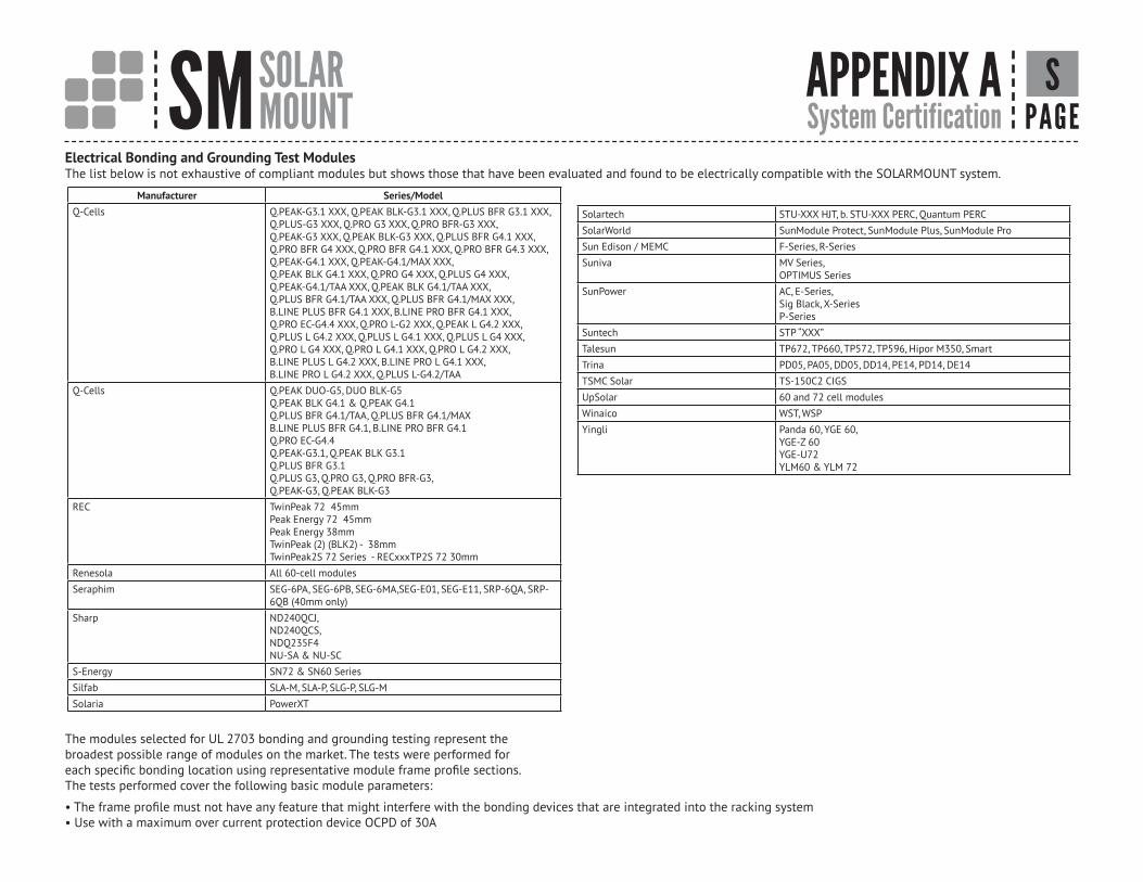
• The frame profile must not have any feature that might interfere with the bonding devices that are integrated into the racking system• Use with a maximum over current protection device OCPD of 30A
The modules selected for UL 2703 bonding and grounding testing represent the broadest possible range of modules on the market. The tests were performed for each specific bonding location using representative module frame profile sections. The tests performed cover the following basic module parameters:
Electrical Bonding and Grounding Test ModulesThe list below is not exhaustive of compliant modules but shows those that have been evaluated and found to be electrically compatible with the SOLARMOUNT system.
Manufacturer Series/ModelQ-Cells Q.PEAK-G3.1 XXX, Q.PEAK BLK-G3.1 XXX, Q.PLUS BFR G3.1 XXX,
Q.PLUS-G3 XXX, Q.PRO G3 XXX, Q.PRO BFR-G3 XXX,Q.PEAK-G3 XXX, Q.PEAK BLK-G3 XXX, Q.PLUS BFR G4.1 XXX, Q.PRO BFR G4 XXX, Q.PRO BFR G4.1 XXX, Q.PRO BFR G4.3 XXX, Q.PEAK-G4.1 XXX, Q.PEAK-G4.1/MAX XXX,Q.PEAK BLK G4.1 XXX, Q.PRO G4 XXX, Q.PLUS G4 XXX,Q.PEAK-G4.1/TAA XXX, Q.PEAK BLK G4.1/TAA XXX,Q.PLUS BFR G4.1/TAA XXX, Q.PLUS BFR G4.1/MAX XXX,B.LINE PLUS BFR G4.1 XXX, B.LINE PRO BFR G4.1 XXX,Q.PRO EC-G4.4 XXX, Q.PRO L-G2 XXX, Q.PEAK L G4.2 XXX,Q.PLUS L G4.2 XXX, Q.PLUS L G4.1 XXX, Q.PLUS L G4 XXX,Q.PRO L G4 XXX, Q.PRO L G4.1 XXX, Q.PRO L G4.2 XXX,B.LINE PLUS L G4.2 XXX, B.LINE PRO L G4.1 XXX,B.LINE PRO L G4.2 XXX, Q.PLUS L-G4.2/TAA
Q-Cells Q.PEAK DUO-G5, DUO BLK-G5Q.PEAK BLK G4.1 & Q.PEAK G4.1Q.PLUS BFR G4.1/TAA, Q.PLUS BFR G4.1/MAXB.LINE PLUS BFR G4.1, B.LINE PRO BFR G4.1Q.PRO EC-G4.4Q.PEAK-G3.1, Q.PEAK BLK G3.1Q.PLUS BFR G3.1Q.PLUS G3, Q.PRO G3, Q.PRO BFR-G3, Q.PEAK-G3, Q.PEAK BLK-G3
REC TwinPeak 72 45mmPeak Energy 72 45mmPeak Energy 38mmTwinPeak (2) (BLK2) - 38mmTwinPeak2S 72 Series - RECxxxTP2S 72 30mm
Renesola All 60-cell modules
Seraphim SEG-6PA, SEG-6PB, SEG-6MA,SEG-E01, SEG-E11, SRP-6QA, SRP-6QB (40mm only)
Sharp ND240QCJ,ND240QCS,NDQ235F4NU-SA & NU-SC
S-Energy SN72 & SN60 Series
Silfab SLA-M, SLA-P, SLG-P, SLG-M
Solaria PowerXT
Solartech STU-XXX HJT, b. STU-XXX PERC, Quantum PERC
SolarWorld SunModule Protect, SunModule Plus, SunModule Pro
Sun Edison / MEMC F-Series, R-Series
Suniva MV Series,OPTIMUS Series
SunPower AC, E-Series, Sig Black, X-SeriesP-Series
Suntech STP “XXX”
Talesun TP672, TP660, TP572, TP596, Hipor M350, Smart
Trina PD05, PA05, DD05, DD14, PE14, PD14, DE14
TSMC Solar TS-150C2 CIGS
UpSolar 60 and 72 cell modules
Winaico WST, WSP
Yingli Panda 60, YGE 60, YGE-Z 60YGE-U72YLM60 & YLM 72
SM SOLARMOUNT FLASHKIT PRO INSTALLATION PAGE
APPENDIX B T
FASTER INSTALLATION. 25-YEAR WARRANTY.
F L A S H K I T P R O I S T H E C O M P L E T E F L A S H I N G A N D AT TA C H M E N T S O L U T I O N F O R C O M P O S I T I O N R O O F S .
F O R Q U E S T I O N S O R C U S T O M E R S E R V I C E V I S I T U N I R A C . C O M O R C A L L ( 5 0 5 ) 2 4 8 - 2 7 0 2
PRE-INSTALL• Locate roof rafters and snap chalk lines to mark the installation
point for each roof attachment.
• Drill a 7/32” pilot hole at each roof attachment. Fill each pilot hole with sealant.
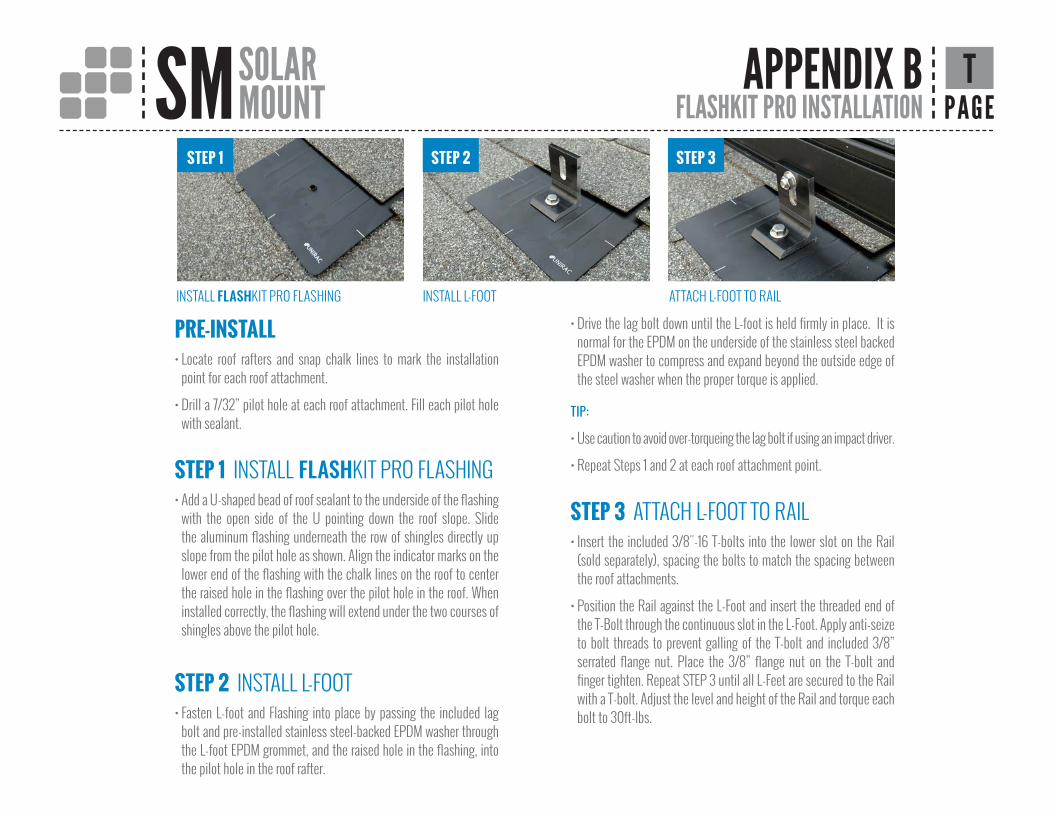
STEP 1 INSTALL FLASHKIT PRO FLASHING• Add a U-shaped bead of roof sealant to the underside of the flashing
with the open side of the U pointing down the roof slope. Slide the aluminum flashing underneath the row of shingles directly up slope from the pilot hole as shown. Align the indicator marks on the lower end of the flashing with the chalk lines on the roof to center the raised hole in the flashing over the pilot hole in the roof. When installed correctly, the flashing will extend under the two courses of shingles above the pilot hole.
STEP 2 INSTALL L-FOOT• Fasten L-foot and Flashing into place by passing the included lag
bolt and pre-installed stainless steel-backed EPDM washer through the L-foot EPDM grommet, and the raised hole in the flashing, into the pilot hole in the roof rafter.
• Drive the lag bolt down until the L-foot is held firmly in place. It is normal for the EPDM on the underside of the stainless steel backed EPDM washer to compress and expand beyond the outside edge of the steel washer when the proper torque is applied.
TIP:
• Use caution to avoid over-torqueing the lag bolt if using an impact driver.
• Repeat Steps 1 and 2 at each roof attachment point.
STEP 3 ATTACH L-FOOT TO RAIL• Insert the included 3/8"-16 T-bolts into the lower slot on the Rail
(sold separately), spacing the bolts to match the spacing between the roof attachments.
• Position the Rail against the L-Foot and insert the threaded end of the T-Bolt through the continuous slot in the L-Foot. Apply anti-seize to bolt threads to prevent galling of the T-bolt and included 3/8” serrated flange nut. Place the 3/8” flange nut on the T-bolt and finger tighten. Repeat STEP 3 until all L-Feet are secured to the Rail with a T-bolt. Adjust the level and height of the Rail and torque each bolt to 30ft-lbs.
INSTALL FLASHKIT PRO FLASHING
STEP 1 STEP 2 STEP 3
INSTALL L-FOOT ATTACH L-FOOT TO RAIL
FLASHKIT PRO INSTALLATION GUIDE
FASTER INSTALLATION. 25-YEAR WARRANTY.
F L A S H K I T P R O I S T H E C O M P L E T E F L A S H I N G A N D AT TA C H M E N T S O L U T I O N F O R C O M P O S I T I O N R O O F S .
F O R Q U E S T I O N S O R C U S T O M E R S E R V I C E V I S I T U N I R A C . C O M O R C A L L ( 5 0 5 ) 2 4 8 - 2 7 0 2
PRE-INSTALL• Locate roof rafters and snap chalk lines to mark the installation
point for each roof attachment.
• Drill a 7/32” pilot hole at each roof attachment. Fill each pilot hole with sealant.
STEP 1 INSTALL FLASHKIT PRO FLASHING• Add a U-shaped bead of roof sealant to the underside of the flashing
with the open side of the U pointing down the roof slope. Slide the aluminum flashing underneath the row of shingles directly up slope from the pilot hole as shown. Align the indicator marks on the lower end of the flashing with the chalk lines on the roof to center the raised hole in the flashing over the pilot hole in the roof. When installed correctly, the flashing will extend under the two courses of shingles above the pilot hole.
STEP 2 INSTALL L-FOOT• Fasten L-foot and Flashing into place by passing the included lag
bolt and pre-installed stainless steel-backed EPDM washer through the L-foot EPDM grommet, and the raised hole in the flashing, into the pilot hole in the roof rafter.
• Drive the lag bolt down until the L-foot is held firmly in place. It is normal for the EPDM on the underside of the stainless steel backed EPDM washer to compress and expand beyond the outside edge of the steel washer when the proper torque is applied.
TIP:
• Use caution to avoid over-torqueing the lag bolt if using an impact driver.
• Repeat Steps 1 and 2 at each roof attachment point.
STEP 3 ATTACH L-FOOT TO RAIL• Insert the included 3/8"-16 T-bolts into the lower slot on the Rail
(sold separately), spacing the bolts to match the spacing between the roof attachments.
• Position the Rail against the L-Foot and insert the threaded end of the T-Bolt through the continuous slot in the L-Foot. Apply anti-seize to bolt threads to prevent galling of the T-bolt and included 3/8” serrated flange nut. Place the 3/8” flange nut on the T-bolt and finger tighten. Repeat STEP 3 until all L-Feet are secured to the Rail with a T-bolt. Adjust the level and height of the Rail and torque each bolt to 30ft-lbs.
INSTALL FLASHKIT PRO FLASHING
STEP 1 STEP 2 STEP 3
INSTALL L-FOOT ATTACH L-FOOT TO RAIL
FLASHKIT PRO INSTALLATION GUIDE