Mount Sinai Health System Emergency Ventilator Sharing ...
17
Mount Sinai Health System Emergency Ventilator Sharing Protocol This document is a working protocol and is subject to revision Version 1.0 Version Date: March 26, 2020 Protocol Developed By: Martin Chen MD Anjan Shah MD Ronak Shah MD George Zhou MD Erica Kane MD Garrett Burnett MD Chang Park MD Daniel Katz MD Shams Ranginwala MBA, RRT-NPS, CPFT Matthew Levin MD We would like to acknowledge the team and protocol developed at Columbia/NYP which served as a template and guide for this document. Purpose: The purpose of this document is to describe the implementation of a shared (also referred to herein as split) ventilator protocol for the Mount Sinai Health System (MSHS) for use when enacting Crisis Standards of Care at hospitals within the MSHS, when potentially rescue-able patients who require mechanical ventilation would otherwise be denied ventilation because of lack of availability. This protocol poses significant risks to both patients and does not in any way reflect the normal standard of care within the MSHS. It has been developed to respond to the unique situation caused by the COVID-19 Crisis in New York City. Patients should be placed on ventilators individually, unless the supply of ventilators is completely exhausted and they would otherwise be expected to die. 1
Transcript of Mount Sinai Health System Emergency Ventilator Sharing ...

Mount Sinai Health System Emergency Ventilator Sharing Protocol This document is a working protocol and is subject to revision
Version 1.0 Version Date: March 26, 2020
Protocol Developed By: Martin Chen MD Anjan Shah MD Ronak Shah MD George Zhou MD Erica Kane MD Garrett Burnett MD Chang Park MD Daniel Katz MD Shams Ranginwala MBA, RRT-NPS, CPFT Matthew Levin MD We would like to acknowledge the team and protocol developed at Columbia/NYP which served as a template and guide for this document. Purpose: The purpose of this document is to describe the implementation of a shared (also referred to herein as split) ventilator protocol for the Mount Sinai Health System (MSHS) for use when enacting Crisis Standards of Care at hospitals within the MSHS, when potentially rescue-able patients who require mechanical ventilation would otherwise be denied ventilation because of lack of availability. This protocol poses significant risks to both patients and does not in any way reflect the normal standard of care within the MSHS. It has been developed to respond to the unique situation caused by the COVID-19 Crisis in New York City. Patients should be placed on ventilators individually, unless the supply of ventilators is completely exhausted and they would otherwise be expected to die.
1
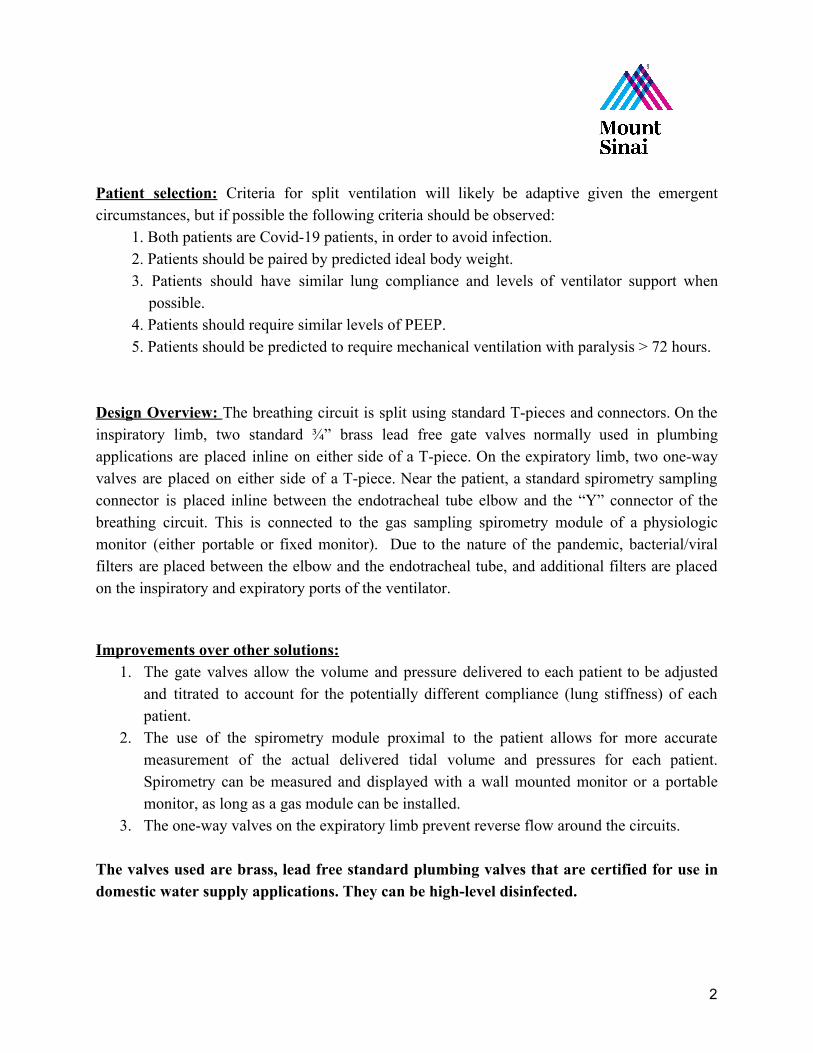
Patient selection: Criteria for split ventilation will likely be adaptive given the emergent circumstances, but if possible the following criteria should be observed:
1. Both patients are Covid-19 patients, in order to avoid infection. 2. Patients should be paired by predicted ideal body weight. 3. Patients should have similar lung compliance and levels of ventilator support when
possible. 4. Patients should require similar levels of PEEP. 5. Patients should be predicted to require mechanical ventilation with paralysis > 72 hours.
Design Overview: The breathing circuit is split using standard T-pieces and connectors. On the inspiratory limb, two standard ¾” brass lead free gate valves normally used in plumbing applications are placed inline on either side of a T-piece. On the expiratory limb, two one-way valves are placed on either side of a T-piece. Near the patient, a standard spirometry sampling connector is placed inline between the endotracheal tube elbow and the “Y” connector of the breathing circuit. This is connected to the gas sampling spirometry module of a physiologic monitor (either portable or fixed monitor). Due to the nature of the pandemic, bacterial/viral filters are placed between the elbow and the endotracheal tube, and additional filters are placed on the inspiratory and expiratory ports of the ventilator. Improvements over other solutions:
1. The gate valves allow the volume and pressure delivered to each patient to be adjusted and titrated to account for the potentially different compliance (lung stiffness) of each patient.
2. The use of the spirometry module proximal to the patient allows for more accurate measurement of the actual delivered tidal volume and pressures for each patient. Spirometry can be measured and displayed with a wall mounted monitor or a portable monitor, as long as a gas module can be installed.
3. The one-way valves on the expiratory limb prevent reverse flow around the circuits. The valves used are brass, lead free standard plumbing valves that are certified for use in domestic water supply applications. They can be high-level disinfected.
2

Figure 1 - example ¾” brass gate valves with solder/sweat connections
3

Parts List 1. 2x ¾” lead free brass gate valves with “sweat” or “solder” connections for inspiratory
limb. These should be available from Home Depot, Lowes, or any plumbing supply store.
2. 2x inline, one way valves for ventilator circuit’s expiratory limb (Mallinckrodt One way valve, 22F x 22M)
3. 2x T piece, 15mm ID / 22mm OD to 2x 19mm ID / 22mm OD (Hudson RCI Trache Tee Oxygenator)
4. 4x 22mm OD male-to-male adapter (blue Airlife Intubation Adapter 001820) 5. 2x 22mm ID female-to-female adapter (clear Mallinckrodt Adapter, Cuff) 6. 2x ventilator circuits 7. 2x yellow spirometry tubing (XXX part number) 8. 2x Bacterial/viral filter (near ETT and expiratory limb) 9. 2x Heat Moisture Exhanger (HME) 10.Spirometry module/monitor 11.Teflon plumbing tape 12.Electrical tape
4
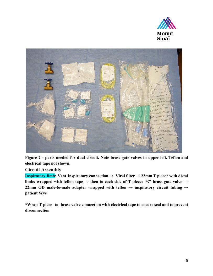
Figure 2 - parts needed for dual circuit. Note brass gate valves in upper left. Teflon and electrical tape not shown. Circuit Assembly Inspiratory limb: Vent Inspiratory connection → Viral filter → 22mm T piece* with distal limbs wrapped with teflon tape → then to each side of T piece: ¾” brass gate valve → 22mm OD male-to-male adapter wrapped with teflon → inspiratory circuit tubing → patient Wye *Wrap T piece -to- brass valve connection with electrical tape to ensure seal and to prevent disconnection
5

Figure 3 - Partially assembled inspiratory limb. Gate valve has been attached to one limb of the T-piece using teflon tape for snug fit. Filter on the T-piece stem will attach to ventilator
6

Figure 4 - both gate check valves have now been installed. 22 mm OD blue male-male adapter with teflon ready to be inserted into check valve.
7
Figure 5 - inspiratory limb of breathing circuit attached to other side of 22 mm OD blue male-male adapter
8

Figure 6 Assembled Inspiratory Gate Check Valves. Note red electrical tape used to provide airtight seal. Patient Connection: yellow spirometry tubing → HME → Viral filter → ETT. Make 2, one for each patient.
9

Figure 7 - Assembled patient connection with (left to right) viral/bacterial filter, HME, and spirometry adapter between elbow and patient Wye connector
10

Expiratory limb: expiratory circuit tubing → 22mm OD male-to-male adapter with proximal end wrapped in teflon tape → one-way-valve (22mm ID to 22mm OD) → 22mm ID female-to-female adapter → 22mm T-piece → 22mm ID female-to-female accordion adapter → Vent expiratory return connection
Figure 8 - Components of Expiratory Limb
11

Figure 9 - Assembled expiratory limb, one side only
12

Figure 10 Final assembled expiratory limb with one-way Valves
13

14

Figure 11 - Final assembled dual patient limbs connected to ventilator, in this instance a Puritan Bennett 840.
Figure 12 - GE Carescape Respiratory Module installed in a GE transport monitor
15

Using the Dual-Patient Ventilation Setup Initiation: The ventilator and circuit should be prepared, and usual system checks should be run. Prior to initiating mechanical ventilation the ¾” brass gate valves should be closed completely and then turned one revolution (360 degrees) open. We have found that these valves provide variable, but not linear, resistance to inspiratory flow that is useful when the valves are opened in the range of 120-360 degrees from the fully closed position, although this may vary depending on manufacturer and should be validated before use. Many ventilators will give an error during the leak test. In this case double check all connections and consider re running the circuit test with only one circuit attached. The tidal volume estimated by the ventilator may be inaccurate during two circuit ventilation, necessitating individual tidal volume assessment by spirometry. Management: Split ventilation, as described in this document, should be exclusively used for paralyzed patients on assist control pressure control mode. Paralysis is important to avoid rapid changes in lung compliance that could affect ventilation of the other patient and the system described herein has only been validated under these conditions. Pressure control should be optimized with the average best PEEP for both patients (Use clinical judgement on the appropriate PEEP that both patients can tolerate) and an initial driving pressure and inspiratory time on the ventilator which provides 4-6cc/kg ideal body weight to the least compliant patient (patient A). Thereafter the driving pressure for the more compliant patient (patient B) should be decreased by turning the ¾” brass gate valve slowly counterclockwise until tidal volumes for patient B are also 4-6cc/kg ideal body weight. These parameters were determined experimentally in our anesthesia high fidelity patient simulator laboratory. Monitoring: Ideally, clinicians should continuously monitor each patient for adequate respiration by in line spirometry assessing inspired tidal volume end and peak airway pressure. Continuous monitoring is preferred for patient safety and to limit unnecessary exposure of staff. If continuous spirometry is unavailable these parameters should be assessed and recorded at least every 4 hours on each patient. Routine sampling of arterial blood gases should be analyzed to ensure adequate ventilation and gas exchange, as available. It is expected that ventilation for both patients cannot be optimized. Slight respiratory acidosis is preferred over respiratory alkalosis, in order to minimize risk of ventilator-induced lunge injury. Both patients will receive the same PEEP and FiO2.
16

Discontinuation: Split ventilation should be discontinued immediately upon availability of sufficient ventilators to independently ventilate each patient, or in the event that ventilator weaning is to be attempted and prior to the discontinuation of deep sedation and paralysis.
References:
1. Smith R, Brown J. Simultaneous ventilation of two healthy subjects with a single ventilator. Resuscitation. 2009;80(9):1087. doi:10.1016/j.resuscitation.2009.05.018
2. Amato M, Meade M, Slutsky A, et al. Driving pressure and survival in the acute respiratory distress syndrome. N Engl J Med. 2015;372(8):747-755. doi:10.1056/NEJMsa1410639
3. Branson R, Blakeman T, Robinson B, Johannigman J. Use of a single ventilator to support 4 patients: laboratory evaluation of a limited concept. Respir Care. 2012;57(3):399-403. doi:10.4187/respcare.01236
4. Carvalho P, Thompson WH, Riggs R, Carvalho C, Charan NB. Management of bronchopleural fistula with a variable-resistance valve and a single ventilator. Chest. 1997 May;111(5):1452-4. PMID: 9149613
5. Charan NB, Carvalho CG, Hawk P, Crowley JJ, Carvalho P. Independent lung ventilation with a single ventilator using a variable resistance valve. Chest. 1995 Jan;107(1):256-60. PMID: 7813287
6. Neyman G, Irvin CB. A single ventilator for multiple simulated patients to meet disaster surge. Acad Emerg Med. 2006 Nov;13(11):1246-9. Epub 2006 Aug 2. PMID: 16885402
17