Mould Hydraulic Systems - ALBA · Mould Hydraulic Systems ... 19499 32154 25999 40192 32499 46221...
20
Mould Hydraulic Systems V230T ® V230Tcat.GB01-2006 Hydraulic cylinders - high temperature 230 bar V230T
Transcript of Mould Hydraulic Systems - ALBA · Mould Hydraulic Systems ... 19499 32154 25999 40192 32499 46221...
Mould Hydraulic Systems
V230T
®
V230Tcat.GB01-2006
Hyd
rau
lic c
ylin
der
s - h
igh
tem
per
atu
re 2
30 b
ar
V23
0T
I/2
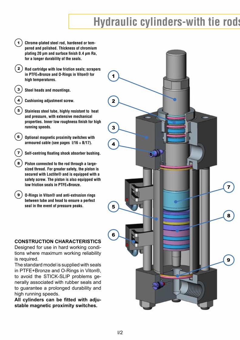
Hydraulic cylinders-with tie rods, for high temperatures 230 bar
Chrome-plated steel rod, hardened or tem-pered and polished. Thickness of chromium plating 20 µm and surface finish 0.4 µm Ra, for a longer durability of the seals.
Rod cartridge with low friction seals; scrapers in PTFE+Bronze and O-Rings in Viton® for high temperatures.
Steel heads and mountings.
Cushioning adjustment screw.
Stainless steel tube, highly resistant to heat and pressure, with extensive mechanical properties. Inner low roughness finish for high running speeds.
Optional magnetic proximity switches with armoured cable (see pages I/16 ÷ B/17).
Self-centring floating shock absorber bushing.
Piston connected to the rod through a large-sized thread. For greater safety, the piston is secured with Loctite® and is equipped with a safety screw. The piston is also equipped with low friction seals in PTFE+Bronze.
O-Rings in Viton® and anti-extrusion rings between tube and head to ensure a perfect seal in the event of pressure peaks.
1
2
3
5
6
7
CONSTRUCTION CHARACTERISTICSDesigned for use in hard working condi-tions where maximum working reliability is required.The standard model is supplied with seals in PTFE+Bronze and O-Rings in Viton®, to avoid the STICK-SLIP problems ge-nerally associated with rubber seals and to guarantee a prolonged durability and high running speeds. All cylinders can be fitted with adju-stable magnetic proximity switches.
8
4
9
2
1
3
7
5
8
6
9
4
I/3
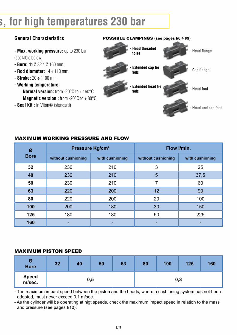
Hydraulic cylinders-with tie rods, for high temperatures 230 barGeneral Characteristics
- Max. working pressure: up to 230 bar(see table below)- Bore: da Ø 32 a Ø 160 mm.- Rod diameter: 14 ÷ 110 mm.- Stroke: 20 ÷ 1100 mm. - Working temperature: Normal version: from -20°C to + 160°C Magnetic version : from -20°C to + 80°C- Seal Kit : in Viton® (standard)
- Head threaded holes
- Extended cap tie rods
- Extended head tie rods
- Head flange
- Cap flange
- Head foot
- Head and cap foot
POSSIBLE CLAMPINGS (see pages I/6 ÷ I/9)
MAXIMUM WORKING PRESSURE AND FLOW
Ø Bore
Pressure Kg/cm2 Flow l/min.
without cushioning with cushioning without cushioning with cushioning
32 230 210 3 25
40 230 210 5 37,5
50 230 210 7 60
63 220 200 12 90
80 220 200 20 100
100 200 180 30 150
125 180 180 50 225
160 - - - -
MAXIMUM PISTON SPEED
Ø Bore
32 40 50 63 80 100 125 160
Speedm/sec.
0,5 0,3
- The maximum impact speed between the piston and the heads, where a cushioning system has not been adopted, must never exceed 0.1 m/sec.
- As the cylinder will be operating at higt speeds, check the maximum impact speed in relation to the mass and pressure (see pages I/10).
I/4
C
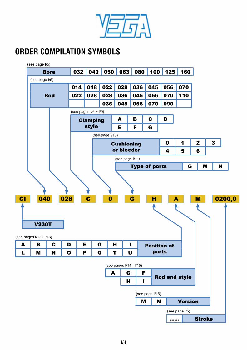
V230T
028040 H M
ORDER COMPILATION SYMBOLS
G0 ACI 0200,0
A B C D E G H I Position of ports L M N O P Q T U
(see pages I/12 - I/13)
A G FRod end style
H I
(see pages I/14 - I/15)
M N Version
(see page I/16)
...,.. Stroke
(see page I/5)
Rod
014 018 022 028 036 045 056 070
022 028 028 036 045 056 070 110
036 045 056 070 090
(see page I/5)
Bore 032 040 050 063 080 100 125 160
(see page I/5)
Type of ports G M N
(see page I/11)
Clamping style
A B C D
E F G
(see pages I/6 ÷ I/9)
Cushioning or bleeder
0 1 2 3
4 5 6
(see page I/10)
I/5
Hydraulic cylinders- high temperatures 230 bar
ØBore
0020
,0
0050
,0
0080
,0
0100
,0
0125
,0
0160
,0
0200
,0
0250
,0
0300
,0
0350
,0
0400
,0
0500
,0
0600
,0
0700
,0
0800
,0
0900
,0
1000
,0
1100
,0
32
40
50
63
80
100
125
160
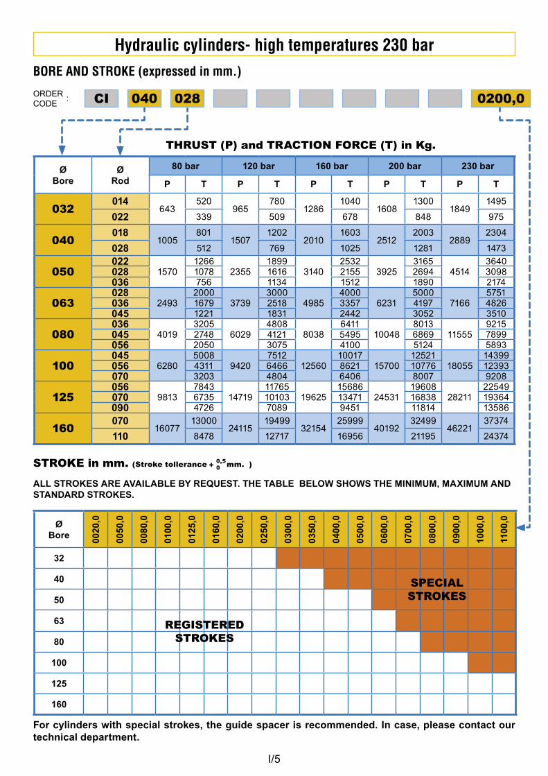
BORE AND STROKE (expressed in mm.)
ORDERCODE
:
ØBore
ØRod
80 bar 120 bar 160 bar 200 bar 230 bar
P T P T P T P T P T
032014
643520
965780
12861040
16081300
18491495
022 339 509 678 848 975
040018
1005801
15071202
20101603
25122003
28892304
028 512 769 1025 1281 1473
050022
15701266
23551899
31402532
39253165
45143640
028 1078 1616 2155 2694 3098036 756 1134 1512 1890 2174
063028
24932000
37393000
49854000
62315000
71665751
036 1679 2518 3357 4197 4826045 1221 1831 2442 3052 3510
080036
40193205
60294808
80386411
100488013
115559215
045 2748 4121 5495 6869 7899056 2050 3075 4100 5124 5893
100045
62805008
94207512
1256010017
1570012521
1805514399
056 4311 6466 8621 10776 12393070 3203 4804 6406 8007 9208
125056
98137843
1471911765
1962515686
2453119608
2821122549
070 6735 10103 13471 16838 19364090 4726 7089 9451 11814 13586
160070
1607713000
2411519499
3215425999
4019232499
4622137374
110 8478 12717 16956 21195 24374
THRUST (P) and TRACTION FORCE (T) in Kg.
028040CI 0200,0
STROKE in mm. (Stroke tollerance mm. )
ALL STROKES ARE AVAILABLE BY REQUEST. THE TABLE BELOW SHOWS THE MINIMUM, MAXIMUM AND STANDARD STROKES.
+ 0,5
0
REGISTERED STROKES
SPECIAL STROKES
For cylinders with special strokes, the guide spacer is recommended. In case, please contact our technical department.
I/6
Hydraulic cylinders- high temperatures 230 bar
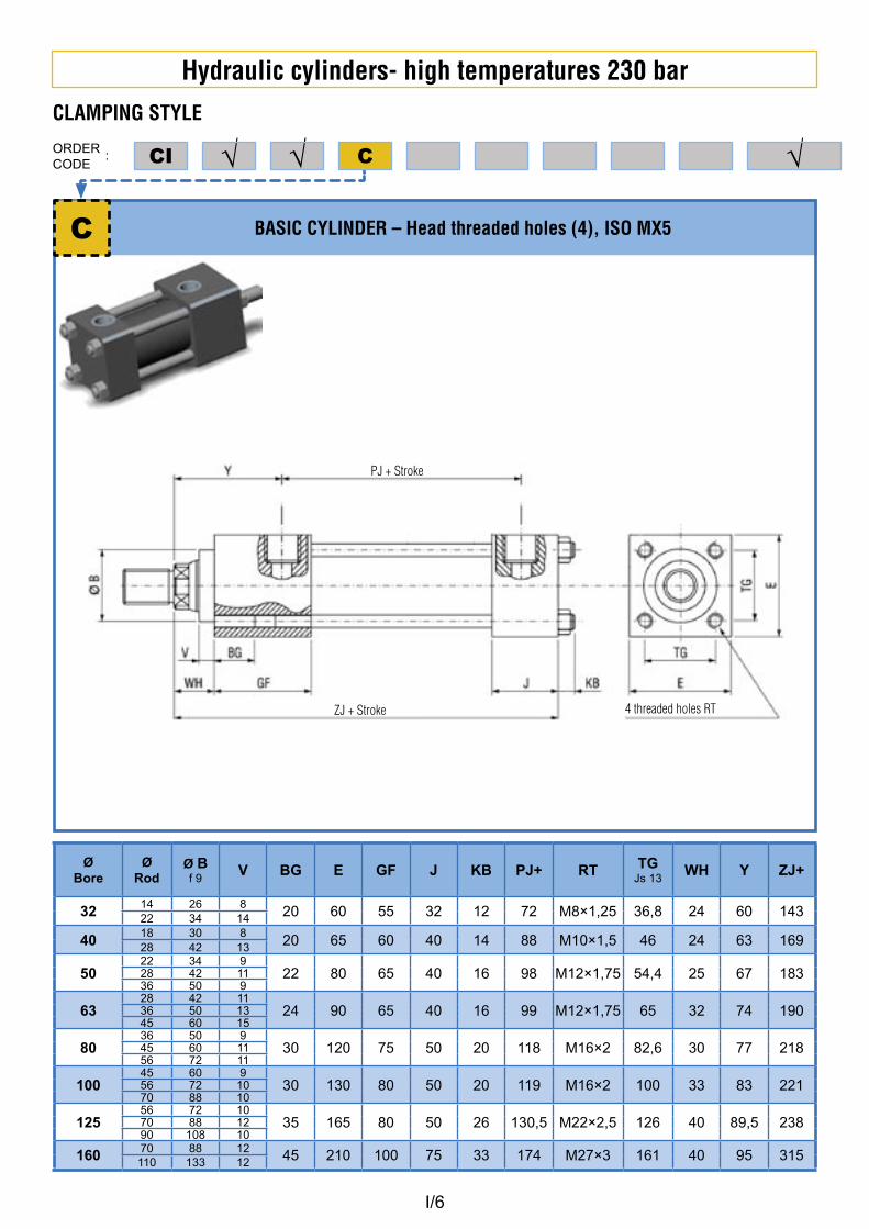
BASIC CYLINDER – Head threaded holes (4), ISO MX5
ØBore
ØRod
Ø Bf 9
V BG E GF J KB PJ+ RT TGJs 13
WH Y ZJ+
3214 26 8
20 60 55 32 12 72 M8×1,25 36,8 24 60 14322 34 14
4018 30 8
20 65 60 40 14 88 M10×1,5 46 24 63 16928 42 13
5022 34 9
22 80 65 40 16 98 M12×1,75 54,4 25 67 18328 42 1136 50 9
6328 42 11
24 90 65 40 16 99 M12×1,75 65 32 74 19036 50 1345 60 15
8036 50 9
30 120 75 50 20 118 M16×2 82,6 30 77 21845 60 1156 72 11
10045 60 9
30 130 80 50 20 119 M16×2 100 33 83 22156 72 1070 88 10
12556 72 10
35 165 80 50 26 130,5 M22×2,5 126 40 89,5 23870 88 1290 108 10
160 70 88 12 45 210 100 75 33 174 M27×3 161 40 95 315110 133 12
C
CLAMPING STYLE
ORDERCODE
: C√√CI √
PJ + Stroke
ZJ + Stroke 4 threaded holes RT
I/7
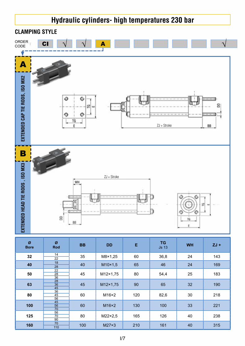
Hydraulic cylinders- high temperatures 230 barEX
TEND
ED C
AP T
IE R
ODS,
ISO
MX2
EXTE
NDED
HEA
D TI
E RO
DS ,
ISO
MX3
A
CLAMPING STYLE
ORDERCODE
: A√√CI √
B
ØBore
ØRod BB DD E TG
Js 13WH ZJ +
3214
35 M8×1,25 60 36,8 24 14322
4018
40 M10×1,5 65 46 24 16928
5022
45 M12×1,75 80 54,4 25 1832836
6328
45 M12×1,75 90 65 32 1903645
8036
60 M16×2 120 82,6 30 2184556
10045
60 M16×2 130 100 33 2215670
12556
80 M22×2,5 165 126 40 2387090
160 70 100 M27×3 210 161 40 315110
ZJ + Stroke
ZJ + Stroke
I/8
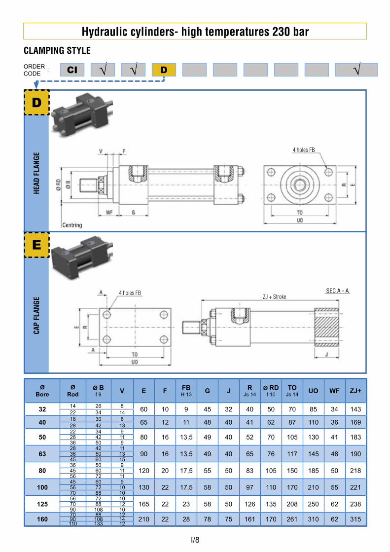
Hydraulic cylinders- high temperatures 230 barHE
AD F
LANG
E CA
P FL
ANGE
D
CLAMPING STYLE
ORDERCODE
: D√√CI √
E
Centring
ØBore
ØRod
Ø Bf 9
V E F FBH 13
G J RJs 14
Ø RDf 10
TOJs 14
UO WF ZJ+
3214 26 8
60 10 9 45 32 40 50 70 85 34 14322 34 14
4018 30 8
65 12 11 48 40 41 62 87 110 36 16928 42 13
5022 34 9
80 16 13,5 49 40 52 70 105 130 41 18328 42 1136 50 9
6328 42 11
90 16 13,5 49 40 65 76 117 145 48 19036 50 1345 60 15
8036 50 9
120 20 17,5 55 50 83 105 150 185 50 21845 60 1156 72 11
10045 60 9
130 22 17,5 58 50 97 110 170 210 55 22156 72 1070 88 10
12556 72 10
165 22 23 58 50 126 135 208 250 62 23870 88 1290 108 10
16070 88 12
210 22 28 78 75 161 170 261 310 62 31590 108 14110 133 12
4 holes FB
4 holes FBZJ + Stroke
SEC A - A
I/9
Hydraulic cylinders- high temperatures 230 barHE
AD F
OOT
HEAD
AND
CAP
FOO
T
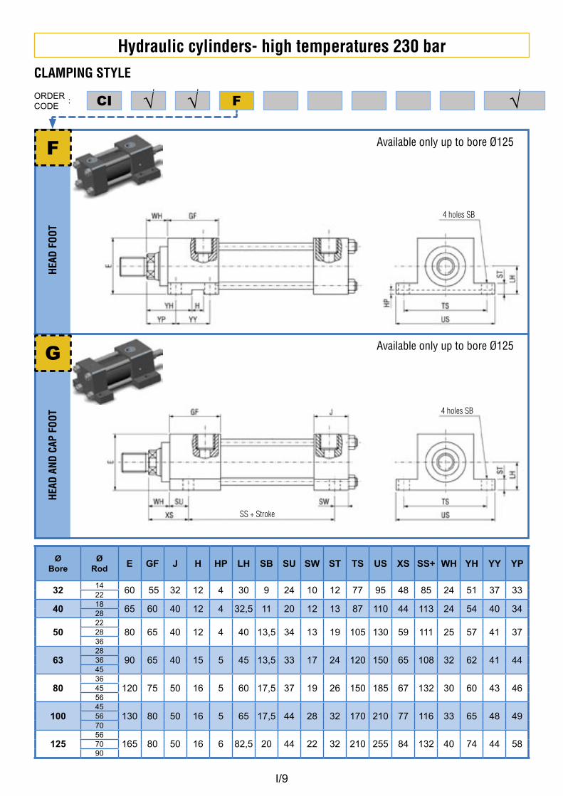
F
CLAMPING STYLE
ORDERCODE
: F√√CI √
G
ØBore
ØRod E GF J H HP LH SB SU SW ST TS US XS SS+ WH YH YY YP
3214
60 55 32 12 4 30 9 24 10 12 77 95 48 85 24 51 37 3322
4018
65 60 40 12 4 32,5 11 20 12 13 87 110 44 113 24 54 40 3428
5022
80 65 40 12 4 40 13,5 34 13 19 105 130 59 111 25 57 41 372836
6328
90 65 40 15 5 45 13,5 33 17 24 120 150 65 108 32 62 41 443645
8036
120 75 50 16 5 60 17,5 37 19 26 150 185 67 132 30 60 43 464556
10045
130 80 50 16 5 65 17,5 44 28 32 170 210 77 116 33 65 48 495670
12556
165 80 50 16 6 82,5 20 44 22 32 210 255 84 132 40 74 44 587090
Available only up to bore Ø125
Available only up to bore Ø125
4 holes SB
4 holes SB
SS + Stroke
I/10
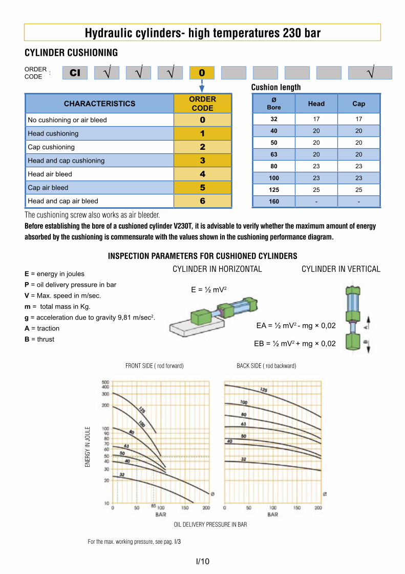
Hydraulic cylinders- high temperatures 230 barCYLINDER CUSHIONING
ORDERCODE
: √√√ 0 CI √
CHARACTERISTICSORDERCODE
No cushioning or air bleed 0
Head cushioning 1
Cap cushioning 2
Head and cap cushioning 3
Head air bleed 4
Cap air bleed 5
Head and cap air bleed 6
ØBore Head Cap
32 17 17
40 20 20
50 20 20
63 20 20
80 23 23
100 23 23
125 25 25
160 - -
The cushioning screw also works as air bleeder.Before establishing the bore of a cushioned cylinder V230T, it is advisable to verify whether the maximum amount of energy absorbed by the cushioning is commensurate with the values shown in the cushioning performance diagram.
Cushion length
INSPECTION PARAMETERS FOR CUSHIONED CYLINDERS
E = energy in joules
P = oil delivery pressure in bar
V = Max. speed in m/sec.
m = total mass in Kg.
g = acceleration due to gravity 9,81 m/sec2.
A = traction
B = thrust
CYLINDER IN HORIZONTAL CYLINDER IN VERTICAL
E = ½ mV2
EA = ½ mV2 - mg × 0,02
EB = ½ mV2 + mg × 0,02
FRONT SIDE ( rod forward) BACK SIDE ( rod backward)
OIL DELIVERY PRESSURE IN BAR
For the max. working pressure, see pag. I/3
ENER
GY IN
JOUL
E
I/11
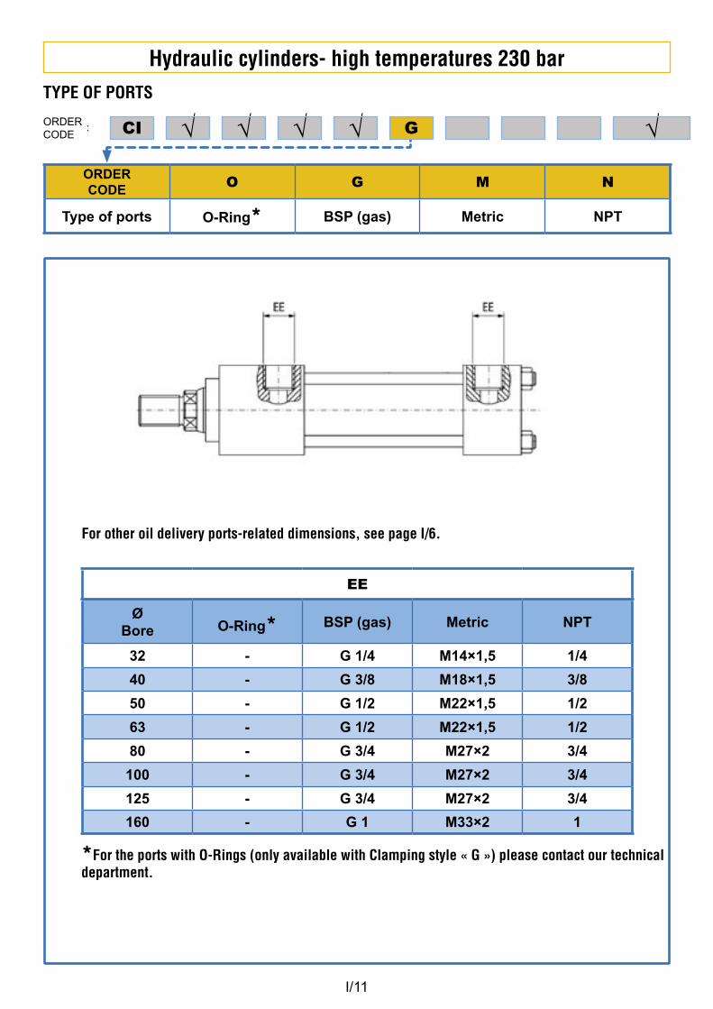
Hydraulic cylinders- high temperatures 230 barTYPE OF PORTS
ORDERCODE
: √√√ √CI √
ORDERCODE
O G M N
Type of ports O-Ring* BSP (gas) Metric NPT
G
EE
ØBore O-Ring* BSP (gas) Metric NPT
32 - G 1/4 M14×1,5 1/4
40 - G 3/8 M18×1,5 3/8
50 - G 1/2 M22×1,5 1/2
63 - G 1/2 M22×1,5 1/2
80 - G 3/4 M27×2 3/4
100 - G 3/4 M27×2 3/4
125 - G 3/4 M27×2 3/4
160 - G 1 M33×2 1
*For the ports with O-Rings (only available with Clamping style « G ») please contact our technical department.
For other oil delivery ports-related dimensions, see page I/6.
I/12
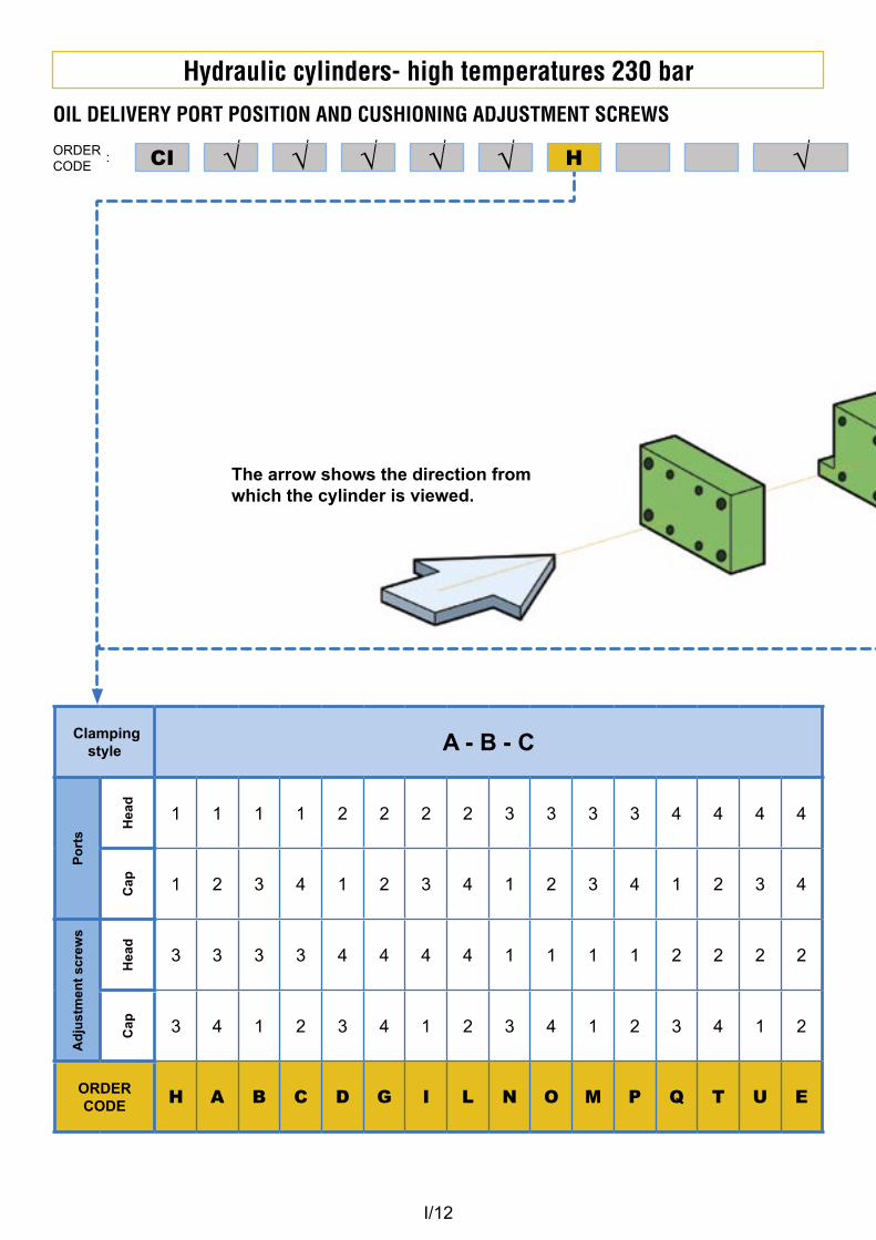
Hydraulic cylinders- high temperatures 230 barOIL DELIVERY PORT POSITION AND CUSHIONING ADJUSTMENT SCREWS
ORDERCODE
: √√√ √CI √√ H
Clamping style A - B - C
Po
rts
Hea
d
1 1 1 1 2 2 2 2 3 3 3 3 4 4 4 4
Cap 1 2 3 4 1 2 3 4 1 2 3 4 1 2 3 4
Ad
just
men
t sc
rew
s
Hea
d
3 3 3 3 4 4 4 4 1 1 1 1 2 2 2 2
Cap 3 4 1 2 3 4 1 2 3 4 1 2 3 4 1 2
ORDER CODE H A B C D G I L N O M P Q T U E
The arrow shows the direction from which the cylinder is viewed.
I/13
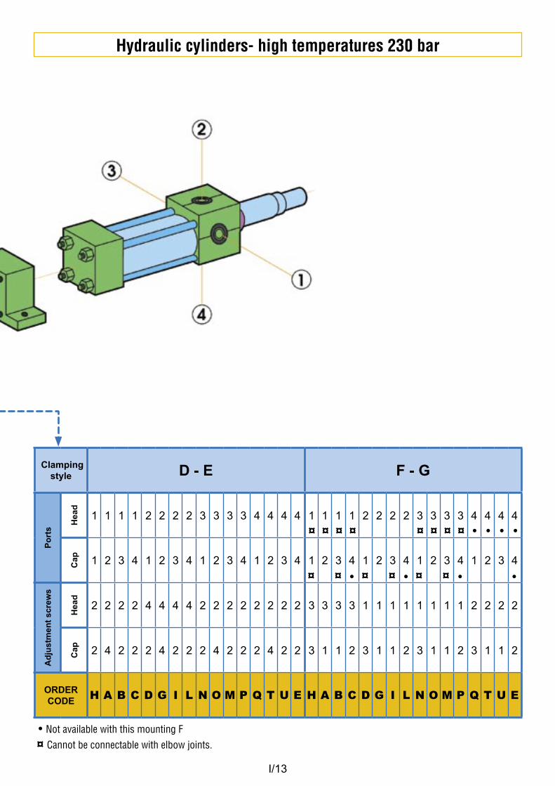
Hydraulic cylinders- high temperatures 230 bar
Clamping style D - E F - G
Po
rts
Hea
d
1 1 1 1 2 2 2 2 3 3 3 3 4 4 4 4 1 1 1 1 2 2 2 2 3 3 3 3 4 4 4 4
Cap 1 2 3 4 1 2 3 4 1 2 3 4 1 2 3 4 1 2 3 4 1 2 3 4 1 2 3 4 1 2 3 4
Ad
just
men
t sc
rew
s
Hea
d
2 2 2 2 4 4 4 4 2 2 2 2 2 2 2 2 3 3 3 3 1 1 1 1 1 1 1 1 2 2 2 2
Cap 2 4 2 2 2 4 2 2 2 4 2 2 2 4 2 2 3 1 1 2 3 1 1 2 3 1 1 2 3 1 1 2
ORDER CODE H A B C D G I L N O M P Q T U E H A B C D G I L N O M P Q T U E
¤ ¤ ¤ ¤ • • • •
¤ ¤ ¤ ¤ ¤ ¤
¤ ¤ ¤ ¤
• • • •
• Not available with this mounting F ¤ Cannot be connectable with elbow joints.
I/14
Hydraulic cylinders- high temperatures 230 barFL
OATI
NG J
OINT
MET
RIC
MAL
E TH
READ
MET
RIC
FEM
ALE
THRE
AD
UNF-
UNEF
MAL
E TH
READ
UNF-
UNEF
FEM
ALE
THRE
AD
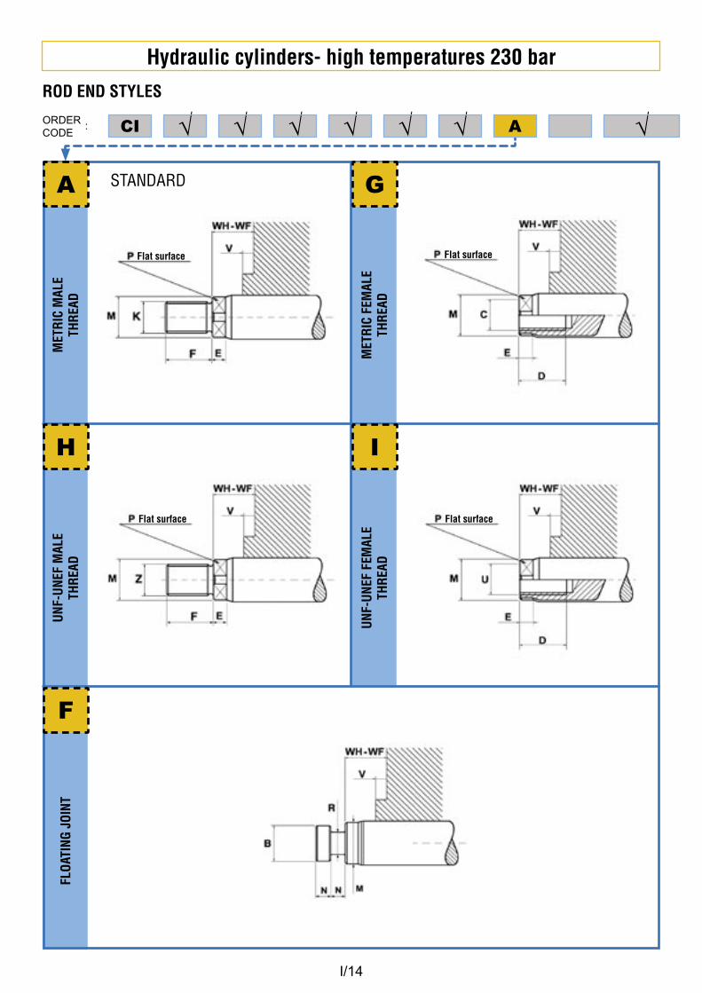
ROD END STYLES
ORDERCODE
: √√√ √√√ ACI √
Flat surface Flat surface
Flat surface Flat surface
A G
H I
STANDARD
F
I/15
Hydraulic cylinders- high temperatures 230 bar
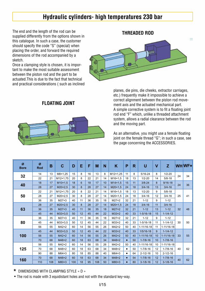
ØBore
ØRod B C D E F M N K P R U V Z WH WF*
3214 13 M8×1,25 15 8 16 13 8 M12×1,25 11 8 5/16-24 8 1/2-20
24 3422 21 M12×1,75 20 8 22 21 14 M16×1,5 18 13 1/2-20 14 5/8-18
4018 17 M10×1,5 18 6 18 17 10 M14×1,5 15 11 3/8-24 8 9/16-18
24 3628 27 M20×2,5 30 8 28 27 14 M20×1,5 24 18 3/4-16 13 3/4-16
5022 21 M12×1,75 20 8 22 21 14 M16×1,5 18 13 1/2-20 9 5/8-18
25 4128 27 M20×2,5 30 8 28 27 14 M20×1,5 24 18 3/4-16 12 3/4-16
36 35 M27×3 40 11 36 35 18 M27×2 32 21 1-12 9 1-12
6328 27 M20×2,5 30 8 28 27 14 M20×1,5 24 18 3/4-16 11 3/4-16
32 4836 35 M27×3 40 11 36 35 18 M27×2 32 21 1-12 13 1-12
45 44 M33×3,5 50 12 45 44 22 M33×2 40 33 1-5/16-18 15 1-1/4-12
8036 35 M27×3 40 11 36 35 18 M27×2 32 21 1-12 9 1-12
30 5045 44 M33×3,5 50 12 45 44 22 M33×2 40 33 1-5/16-18 11 1-1/4-12
56 55 M42×2 60 14 56 55 26 M42×2 50 40 1-11/16-18 11 1-11/16-18
10045 44 M33×3,5 50 12 45 44 22 M33×2 40 33 1/5/16-18 9 1-1/4-12
33 5556 55 M42×2 60 14 56 55 26 M42×2 50 40 1-11/16-18 10 1-11/16-18
70 68 M48×2 60 18 63 68 34 M48×2 • 50 1-7/8-16 10 1-7/8-16
12556 55 M42×2 60 14 56 55 26 M42×2 50 40 1-11/16-18 10 1-11/16-18
40 6270 68 M48×2 60 18 63 68 34 M48×2 • 50 1-7/8-16 12 1-7/8-16
90 88 M64×3 80 18 85 88 40 M64×3 • 64 2-1/2-16 10 2-1/2-16
16070 68 M48×2 60 18 63 68 34 M48×2 • 54 1-7/8-16 12 1-7/8-16
40 62110 108 M80×3 100 18 95 108 50 M80×3 • 80 3-1/8-16 12 3-1/8-16
* DIMENSIONS WITH CLAMPING STYLE « D » • The rod is made with 3 equidistant holes and not with the standard key-way.
The end and the length of the rod can be supplied differently from the options shown in this catalogue. In such a case, the customer should specify the code “S” (special) when placing the order, and forward the required dimensions of the rod accompanied by a sketch.Once a clamping style is chosen, it is impor-tant to make the most suitable assessment between the piston rod and the part to be actuated.This is due to the fact that technical and practical considerations ( such as inclined
planes, die pins, die cheeks, extractor carriages, etc.) frequently make it impossible to achieve a correct alignment between the piston rod move-ment axis and the actuated mechanical part.A simple corrective system is to fit a floating joint rod end “F” which, unlike a threaded attachment system, allows a radial clearance between the rod and the moving part.
As an alternative, you might use a female floating joint on the female thread “G”; in such a case, see the page concerning the ACCESSORIES.
THREADED ROD
FLOATING JOINT
I/16
Hydraulic cylinders- high temperatures 230 bar
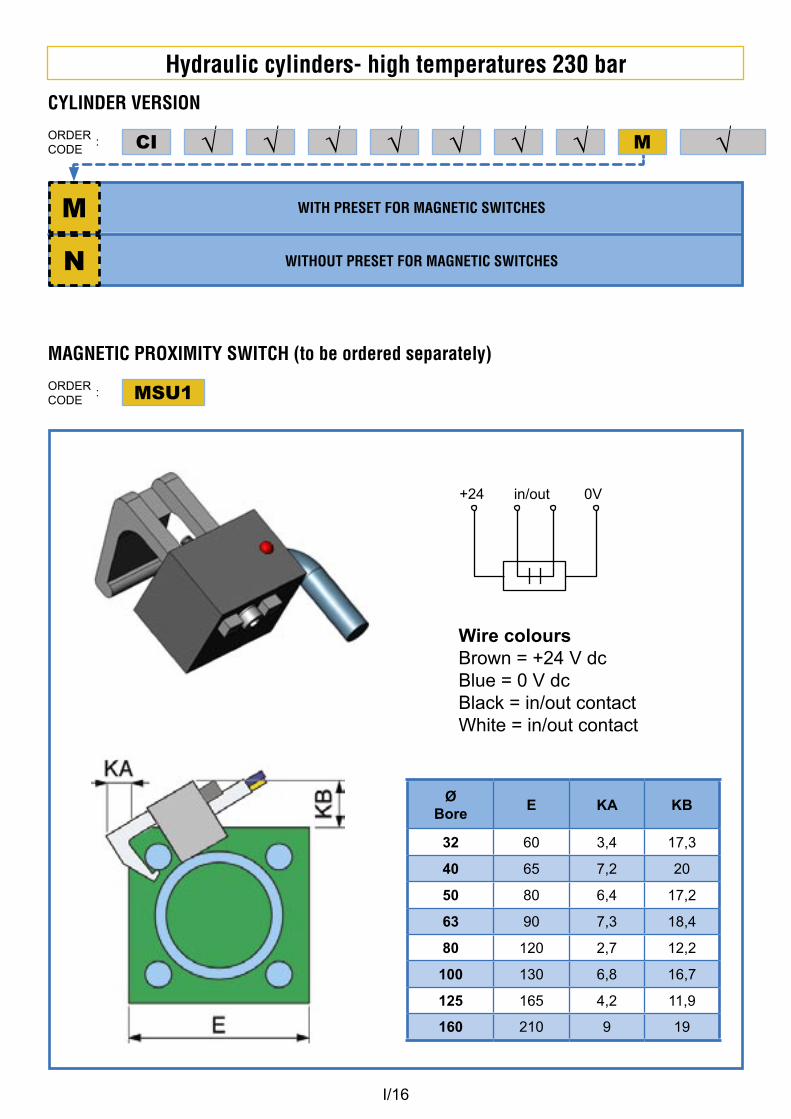
WITH PRESET FOR MAGNETIC SWITCHES
WITHOUT PRESET FOR MAGNETIC SWITCHES
CYLINDER VERSION
ORDERCODE
: √√√ √√√ √CI √
M
N
M
MAGNETIC PROXIMITY SWITCH (to be ordered separately)
ORDERCODE
: MSU1
+24 in/out 0V
Wire coloursBrown = +24 V dcBlue = 0 V dcBlack = in/out contactWhite = in/out contact
ØBore
E KA KB
32 60 3,4 17,3
40 65 7,2 20
50 80 6,4 17,2
63 90 7,3 18,4
80 120 2,7 12,2
100 130 6,8 16,7
125 165 4,2 11,9
160 210 9 19
I/17
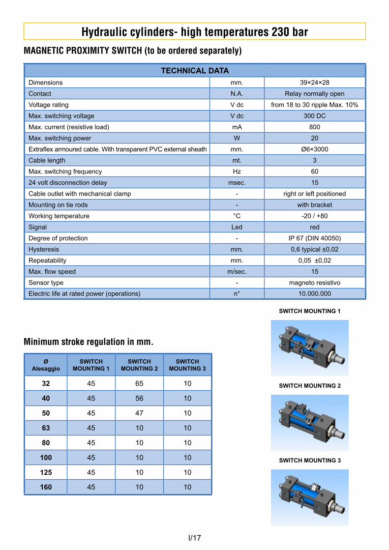
Hydraulic cylinders- high temperatures 230 barMAGNETIC PROXIMITY SWITCH (to be ordered separately)
TECHNICAL DATA
Dimensions mm. 39×24×28
Contact N.A. Relay normally open
Voltage rating V dc from 18 to 30 ripple Max. 10%
Max. switching voltage V dc 300 DC
Max. current (resistive load) mA 800
Max. switching power W 20
Extraflex armoured cable. With transparent PVC external sheath mm. Ø6×3000
Cable length mt. 3
Max. switching frequency Hz 60
24 volt disconnection delay msec. 15
Cable outlet with mechanical clamp - right or left positioned
Mounting on tie rods - with bracket
Working temperature °C -20 / +80
Signal Led red
Degree of protection - IP 67 (DIN 40050)
Hysteresis mm. 0,6 typical ±0,02
Repeatability mm. 0,05 ±0,02
Max. flow speed m/sec. 15
Sensor type - magneto resistivo
Electric life at rated power (operations) n° 10.000.000
ØAlesaggio
SWITCH MOUNTING 1
SWITCH MOUNTING 2
SWITCH MOUNTING 3
32 45 65 10
40 45 56 10
50 45 47 10
63 45 10 10
80 45 10 10
100 45 10 10
125 45 10 10
160 45 10 10
Minimum stroke regulation in mm.
SWITCH MOUNTING 1
SWITCH MOUNTING 2
SWITCH MOUNTING 3
I/18
Hydraulic cylinders- high temperatures 230 bar
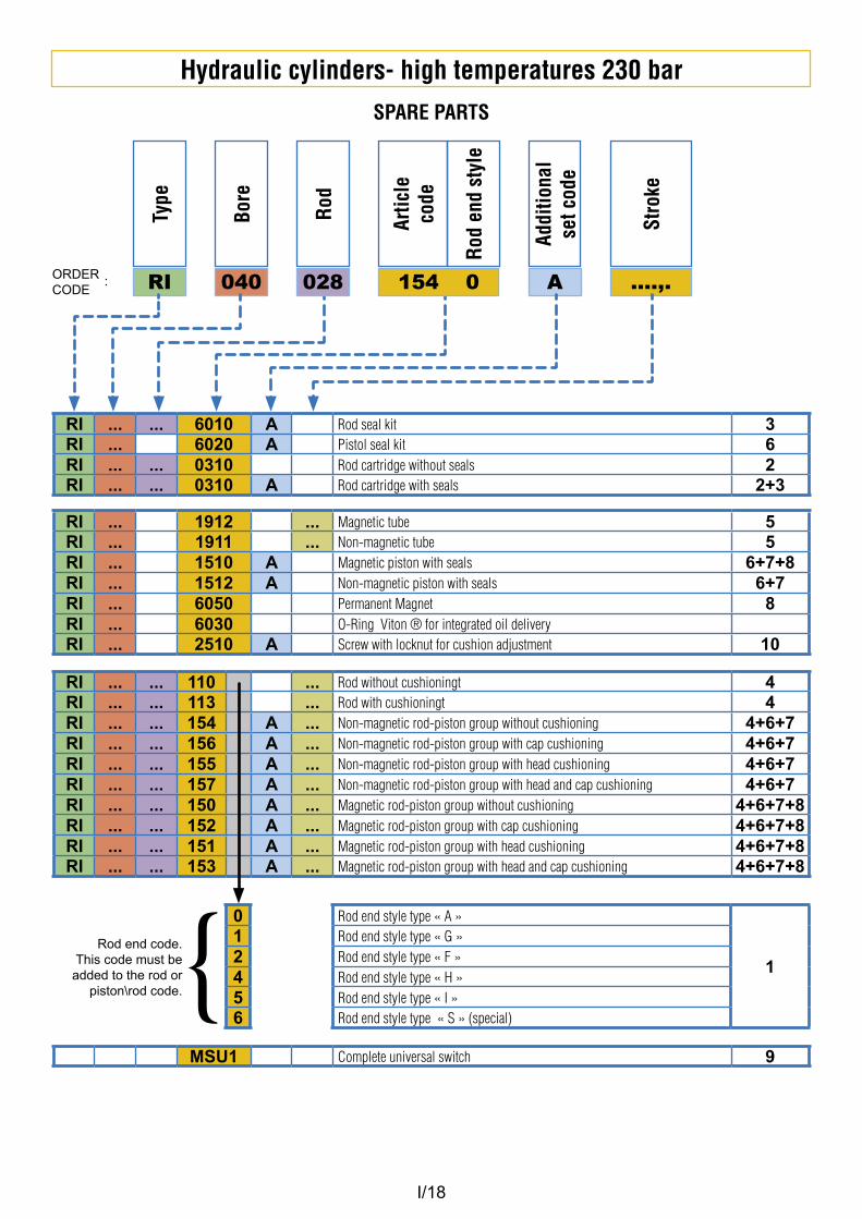
RI ... ... 6010 A Rod seal kit 3RI ... 6020 A Pistol seal kit 6RI ... ... 0310 Rod cartridge without seals 2RI ... ... 0310 A Rod cartridge with seals 2+3
RI ... 1912 ... Magnetic tube 5RI ... 1911 ... Non-magnetic tube 5RI ... 1510 A Magnetic piston with seals 6+7+8RI ... 1512 A Non-magnetic piston with seals 6+7RI ... 6050 Permanent Magnet 8RI ... 6030 O-Ring Viton ® for integrated oil deliveryRI ... 2510 A Screw with locknut for cushion adjustment 10
SPARE PARTS
ORDERCODE
: ....,.
Stro
ke
040
Bore
A
Addi
tiona
l se
t cod
e
RI
Type
028
Rod
154 0
Artic
le
code
Rod
end
styl
e
RI ... ... 110 ... Rod without cushioningt 4RI ... ... 113 ... Rod with cushioningt 4RI ... ... 154 A ... Non-magnetic rod-piston group without cushioning 4+6+7RI ... ... 156 A ... Non-magnetic rod-piston group with cap cushioning 4+6+7RI ... ... 155 A ... Non-magnetic rod-piston group with head cushioning 4+6+7RI ... ... 157 A ... Non-magnetic rod-piston group with head and cap cushioning 4+6+7RI ... ... 150 A ... Magnetic rod-piston group without cushioning 4+6+7+8RI ... ... 152 A ... Magnetic rod-piston group with cap cushioning 4+6+7+8RI ... ... 151 A ... Magnetic rod-piston group with head cushioning 4+6+7+8RI ... ... 153 A ... Magnetic rod-piston group with head and cap cushioning 4+6+7+8
MSU1 Complete universal switch 9
0 Rod end style type « A »
1
1 Rod end style type « G »2 Rod end style type « F »4 Rod end style type « H »5 Rod end style type « I »6 Rod end style type « S » (special)
Rod end code. This code must be
added to the rod or piston\rod code. {
I/19
Hydraulic cylinders- high temperatures 230 bar
1
2
4
3
6
8
9
5
10
7
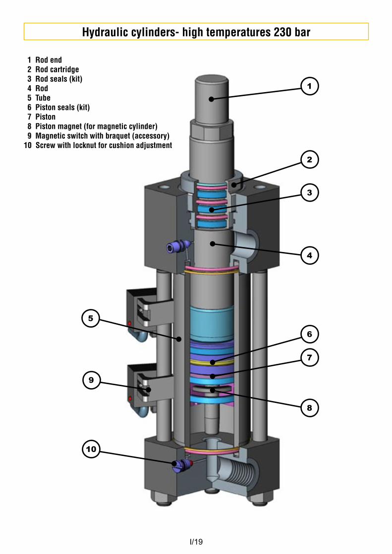
1 Rod end2 Rod cartridge3 Rod seals (kit)4 Rod5 Tube6 Piston seals (kit)7 Piston8 Piston magnet (for magnetic cylinder)9 Magnetic switch with braquet (accessory)
10 Screw with locknut for cushion adjustment
Mould Hydraulic Systems
VEGA S.r.l. Via De Gasperi, 16
IT-21053 CASTELLANZA -VAPhone +39-0331-481077 Italy
Phone +39-0331-480831 ExportFax +39-0331-481149
e-mail. [email protected]