Mototrbo Network Interface Service
37
2013 MOTOTRBO ADP CONFERENCE MOTOTRBO Network Interface Service (IP Wireline Data Gateway) MOTOTRBO ADP GLOBAL ENGINEERING MOTOROLA SOLUTIONS INC., Confidential Restricted
-
Upload
anon849270 -
Category
Documents
-
view
428 -
download
59
description
.
Transcript of Mototrbo Network Interface Service
2013 MOTOTRBO ADP CONFERENCE
MOTOTRBO Network Interface Service (IP Wireline Data Gateway)
MOTOTRBO ADP GLOBAL ENGINEERING
MOTOROLA SOLUTIONS INC., Confidential Restricted
Topics MNIS Deployment Types
MNIS Interface Overview
Data Service Comparison
with Control Station
Interface
Migration to MNIS
Interface
MNIS Capacities
What is New in DDMS
Passive PN
What is New in R2.3 (AES)
Router Requirement
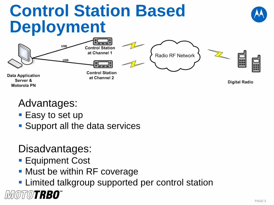
Control Station Based Deployment
Advantages: Easy to set up
Support all the data services
Disadvantages: Equipment Cost
Must be within RF coverage
Limited talkgroup supported per control station
PAGE 3
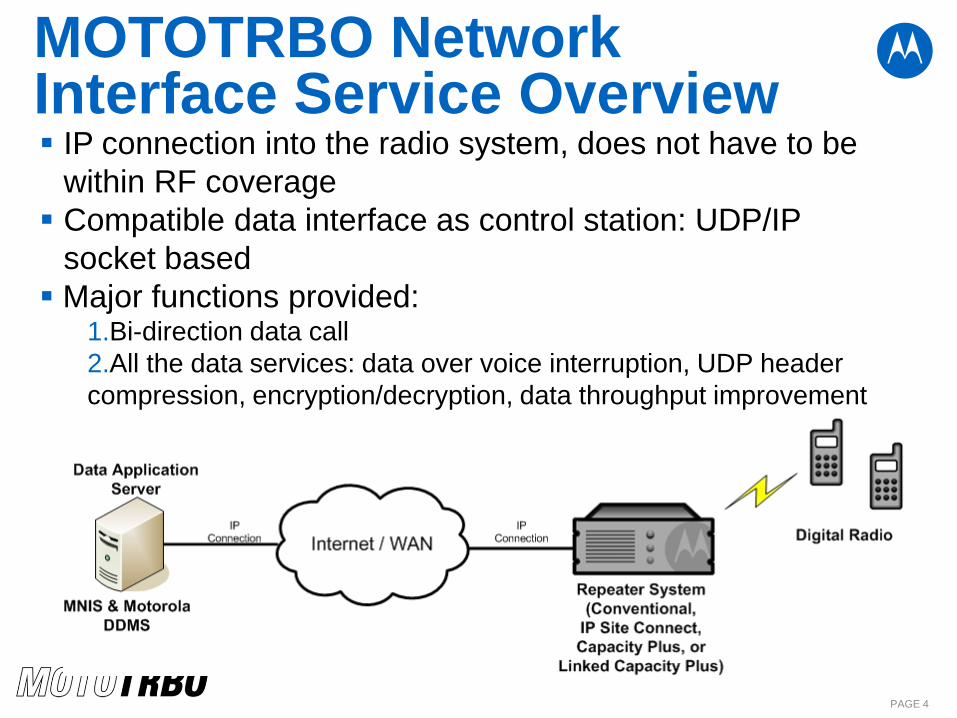
MOTOTRBO Network Interface Service Overview
PAGE 4
IP connection into the radio system, does not have to be
within RF coverage
Compatible data interface as control station: UDP/IP
socket based
Major functions provided: 1.Bi-direction data call
2.All the data services: data over voice interruption, UDP header
compression, encryption/decryption, data throughput improvement
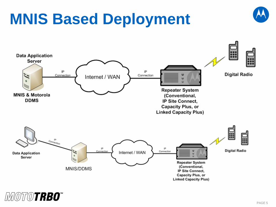
MNIS Based Deployment
PAGE 5
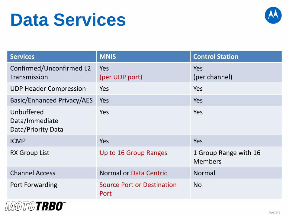
Data Services
Services MNIS Control Station
Confirmed/Unconfirmed L2 Transmission
Yes (per UDP port)
Yes (per channel)
UDP Header Compression Yes Yes
Basic/Enhanced Privacy/AES Yes Yes
Unbuffered Data/Immediate Data/Priority Data
Yes Yes
ICMP Yes Yes
RX Group List Up to 16 Group Ranges 1 Group Range with 16 Members
Channel Access Normal or Data Centric Normal
Port Forwarding Source Port or Destination Port
No
PAGE 6
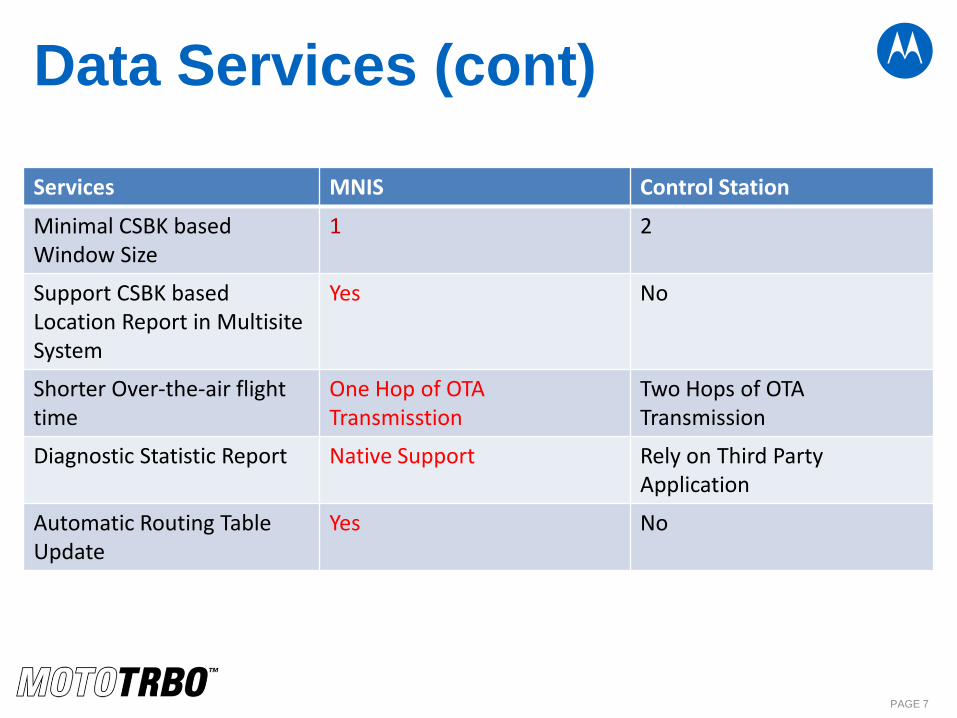
Data Services (cont)
Services MNIS Control Station
Minimal CSBK based Window Size
1 2
Support CSBK based Location Report in Multisite System
Yes No
Shorter Over-the-air flight time
One Hop of OTA Transmisstion
Two Hops of OTA Transmission
Diagnostic Statistic Report Native Support Rely on Third Party Application
Automatic Routing Table Update
Yes No
PAGE 7
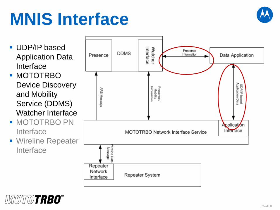
MNIS Interface
UDP/IP based
Application Data
Interface
MOTOTRBO
Device Discovery
and Mobility
Service (DDMS)
Watcher Interface
MOTOTRBO PN
Interface
Wireline Repeater
Interface
PAGE 8
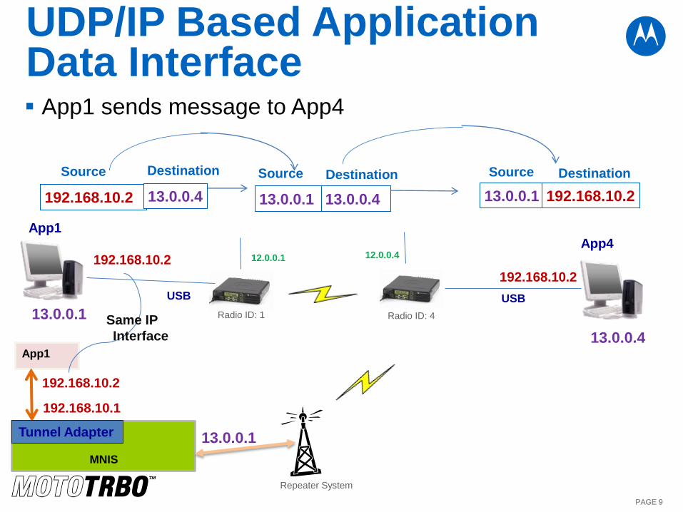
UDP/IP Based Application Data Interface
PAGE 9 PAGE 9
USB
12.0.0.1 12.0.0.4
Radio ID: 1 Radio ID: 4
192.168.10.2
App1 sends message to App4
13.0.0.1
13.0.0.4
192.168.10.2
192.168.10.2 13.0.0.4
Source Destination
13.0.0.1 13.0.0.4
Source Destination
13.0.0.1 192.168.10.2
Source Destination
USB
App1 App4
MNIS
App1
Tunnel Adapter
192.168.10.2
192.168.10.1
13.0.0.1
Repeater System
Same IP
Interface

Migration to the MNIS
Application Layer Protocol
IP Routing/Address Translation
Data Services (transmit interrupt, UDP header
compression…)
PAGE 10
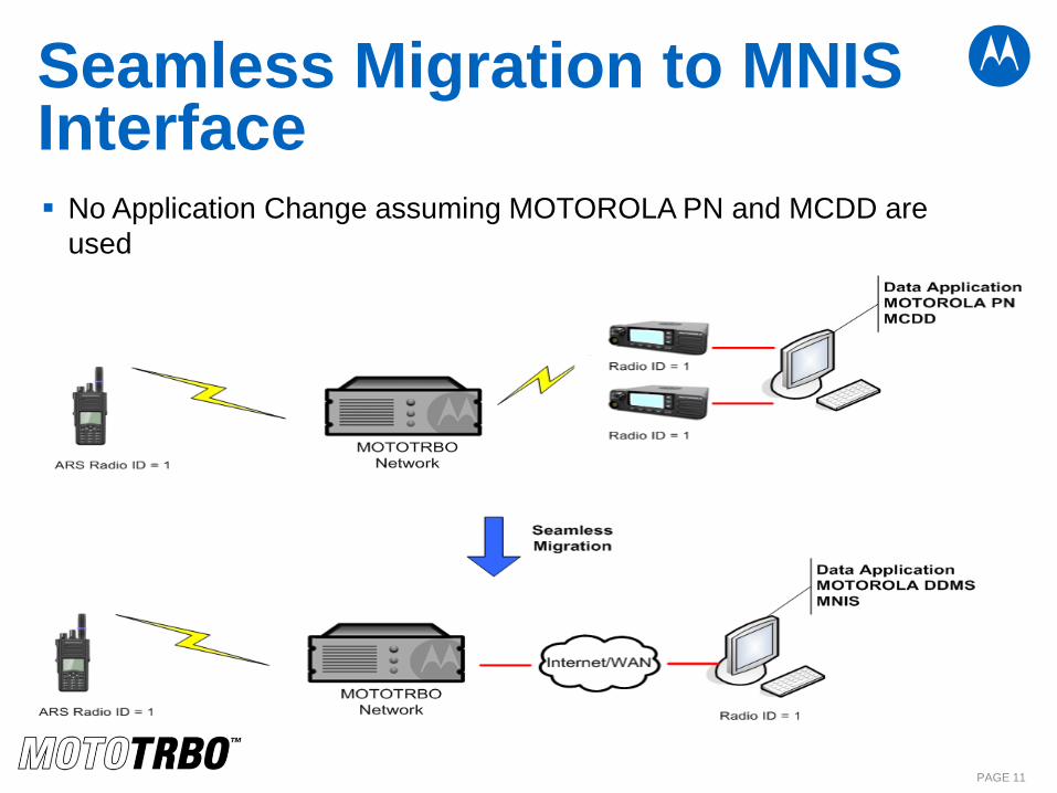
Seamless Migration to MNIS Interface No Application Change assuming MOTOROLA PN and MCDD are
used
PAGE 11

MNIS Supported Systems
PAGE 12
Supported:
Single Site Conventional (excluding Talkaround)
IP Site Connect (Wide/Local Area Channel)
Capacity Plus
Linked Capacity Plus
Data Revert Channel
Enhanced GPS Revert Channel
Not Supported
Analog
Analog and Digital Mixed Mode
MNIS with Conventional System
PAGE 13
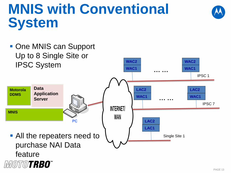
One MNIS can Support
Up to 8 Single Site or
IPSC System
MNIS
Data
Application
Server
Motorola
DDMS
INTERNET/
WAN
WAC1
WAC2
IPSC 1
WAC1
WAC2
… …
WAC1
LAC2
IPSC 7
WAC1
LAC2
… …
LAC1
LAC2
Single Site 1 All the repeaters need to
purchase NAI Data
feature
MNIS with Trunking System
PAGE 14
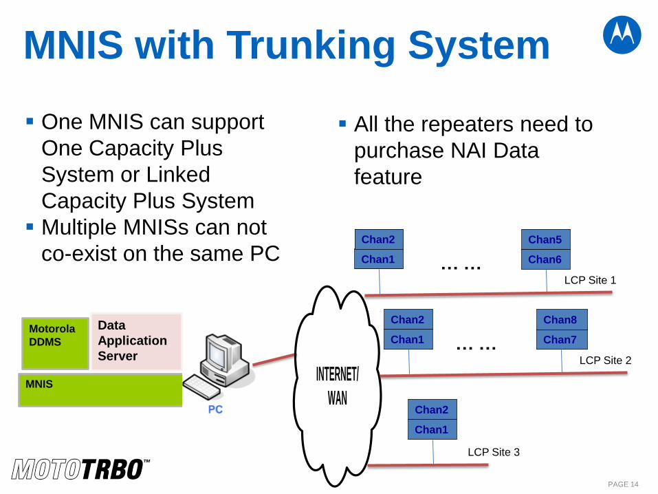
One MNIS can support
One Capacity Plus
System or Linked
Capacity Plus System
Multiple MNISs can not
co-exist on the same PC
MNIS
Data
Application
Server
Motorola
DDMS
INTERNET/
WAN
Chan1
Chan2
LCP Site 1
Chan6
Chan5
… …
Chan1
Chan2
LCP Site 2
Chan7
Chan8
… …
Chan1
Chan2
LCP Site 3
All the repeaters need to
purchase NAI Data
feature
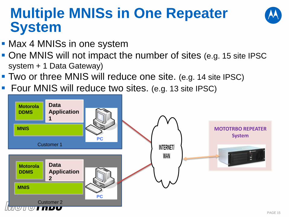
Multiple MNISs in One Repeater System
Max 4 MNISs in one system
One MNIS will not impact the number of sites (e.g. 15 site IPSC
system + 1 Data Gateway)
Two or three MNIS will reduce one site. (e.g. 14 site IPSC)
Four MNIS will reduce two sites. (e.g. 13 site IPSC)
PAGE 15
INTERNET/
WAN
MNIS
Data
Application
1
Motorola
DDMS
Customer 1
MNIS
Data
Application
2
Motorola
DDMS
Customer 2
MOTOTRBO REPEATER System
What are the major configuration parameters in MNIS?
PAGE 16
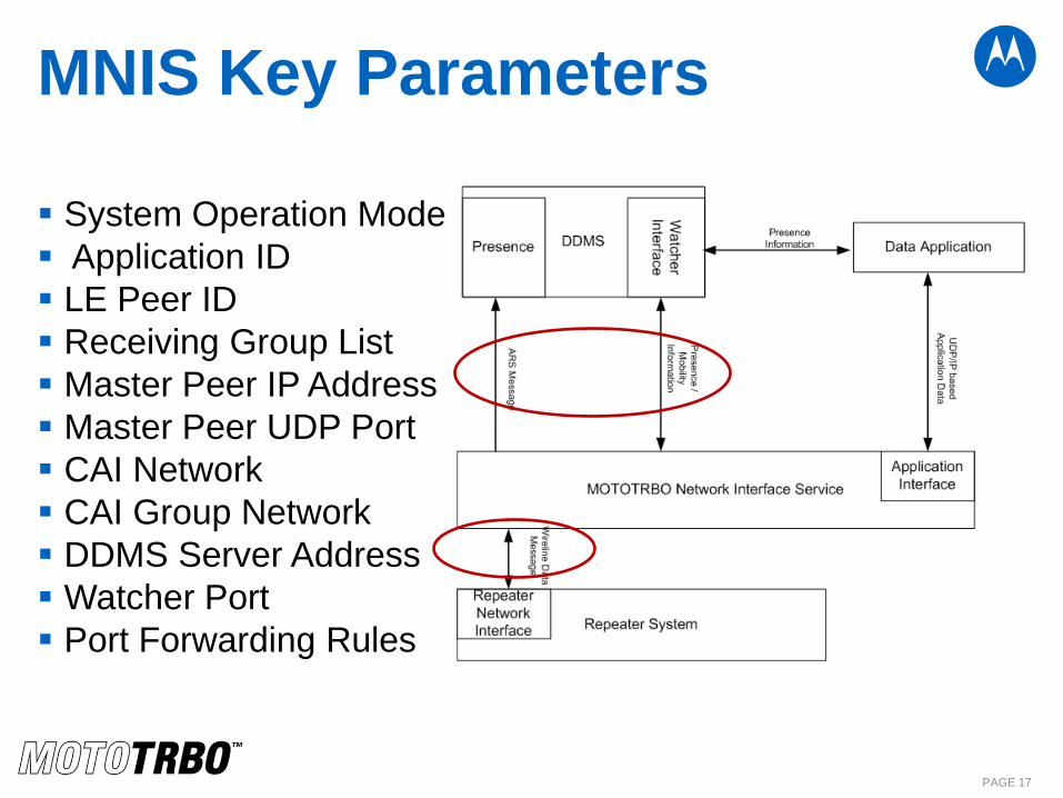
MNIS Key Parameters
System Operation Mode
Application ID
LE Peer ID
Receiving Group List
Master Peer IP Address
Master Peer UDP Port
CAI Network
CAI Group Network
DDMS Server Address
Watcher Port
Port Forwarding Rules
PAGE 17
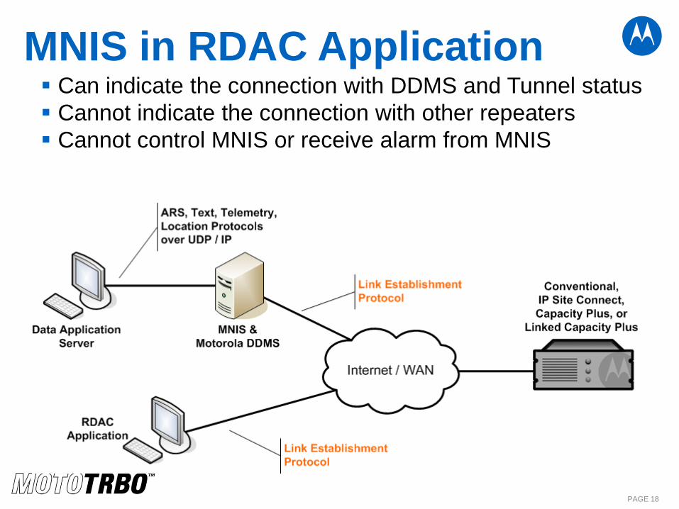
MNIS in RDAC Application
PAGE 18
Can indicate the connection with DDMS and Tunnel status
Cannot indicate the connection with other repeaters
Cannot control MNIS or receive alarm from MNIS
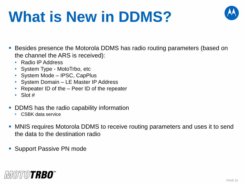
What is New in DDMS?
Besides presence the Motorola DDMS has radio routing parameters (based on
the channel the ARS is received): • Radio IP Address
• System Type - MotoTrbo, etc
• System Mode – IPSC, CapPlus
• System Domain – LE Master IP Address
• Repeater ID of the – Peer ID of the repeater
• Slot #
DDMS has the radio capability information • CSBK data service
MNIS requires Motorola DDMS to receive routing parameters and uses it to send
the data to the destination radio
Support Passive PN mode
PAGE 19
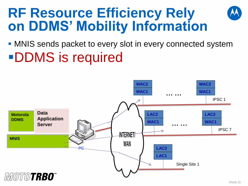
RF Resource Efficiency Rely on DDMS’ Mobility Information MNIS sends packet to every slot in every connected system
DDMS is required
PAGE 20
MNIS
Data
Application
Server
Motorola
DDMS
INTERNET/
WAN
WAC1
WAC2
IPSC 1
WAC1
WAC2
… …
WAC1
LAC2
IPSC 7
WAC1
LAC2
… …
LAC1
LAC2
Single Site 1
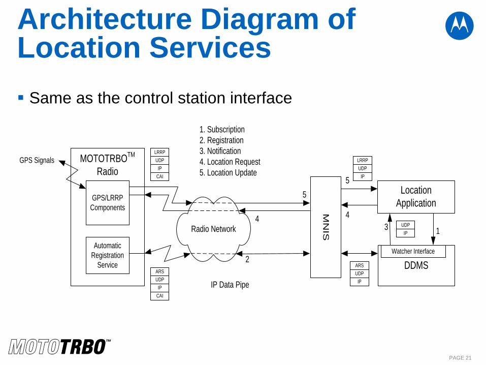
Architecture Diagram of Location Services
Same as the control station interface
PAGE 21
Radio Network
UDP
IP
CAI
UDP
IP
MOTOTRBOTM
Radio
Automatic
Registration
Service
Location
Application
UDP
IPIP Data Pipe
GPS/LRRP
Components
UDP
IP
UDP
IP
CAI5
43 1
2
1. Subscription
2. Registration
3. Notification
4. Location Request
5. Location Update
ARSARS
LRRP
LRRPGPS SignalsM
NIS
DDMS
Watcher Interface
5
4
MNIS and Motorola DDMS Supported Platforms
Windows XP
Windows Server 2003, 2008 R2
Windows 7
Windows 8
PAGE 22
What is New in R2.3
Advanced Encryption Standard (AES)
CSBK Data Support (ARS, Location, Third Party XCMP
Device Raw Data)
PAGE 23
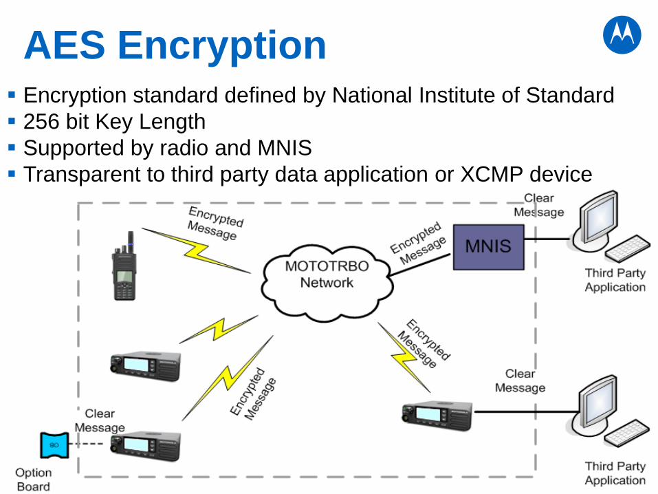
AES Encryption Encryption standard defined by National Institute of Standard
256 bit Key Length
Supported by radio and MNIS
Transparent to third party data application or XCMP device
PAGE 24
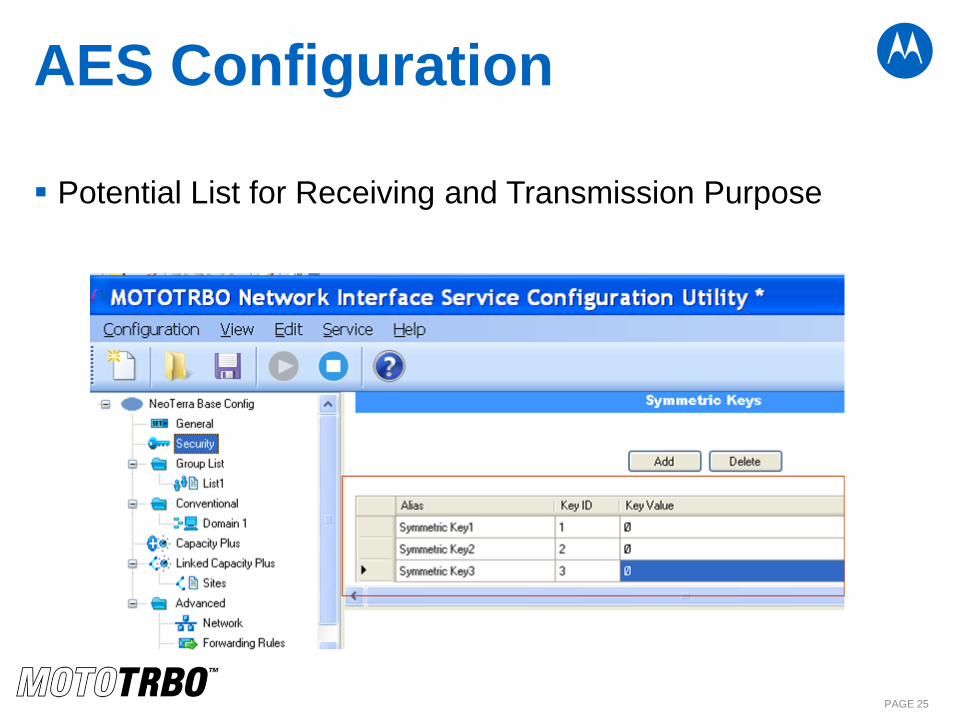
AES Configuration
Potential List for Receiving and Transmission Purpose
PAGE 25
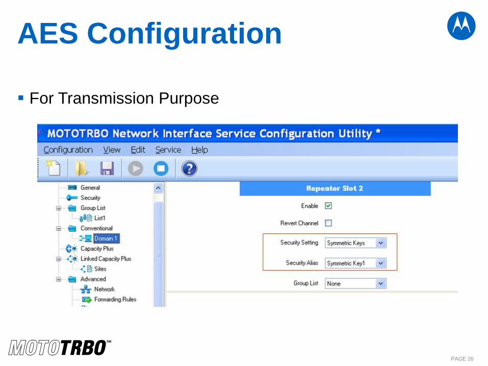
AES Configuration
For Transmission Purpose
PAGE 26
Hair Pinning Router
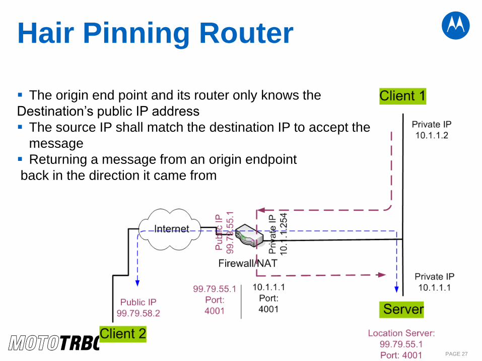
The origin end point and its router only knows the
Destination’s public IP address
The source IP shall match the destination IP to accept the
message
Returning a message from an origin endpoint
back in the direction it came from
PAGE 27
R2.2A Route Requirement
PAGE 28
IPSC • If the IPSC sites are joined together into the same subnet using VPN then hair pinning router is not
required.
• When VPN is not used and more than one networked applications (such as MNIS, RDAC, or apps that
connect to the repeaters directly) or repeater are at the same subnet then hair pinning router is required
for that subnet.
Capacity Plus • All the applications and the repeaters are in the same subnet then hair-pinning router is not required
• Hair-pinning router is required at the master site when the network applications are deployed on a
different subnet
Hair-pinning router is required at non-repeater subnet with more than one network applications.
LCP • All the network applications and the repeaters are in the same subnet as the Master peer then hair-
pinning router is not required when deployed with R2.2 LCP hair pinning enhancements. The non-
master repeater sites do not require hair-pinning routers.
• Hair-pinning router is required at non-master repeater site when one or more network application is
deployed at the non-master repeater sites.
• Hair-pinning router is required at non-repeater subnet with more than one applications.
NOTE: If the network applications are installed on the same PC then they are also on the
same subnet
PAGE 29
Hair-pinning router in Capacity Plus Example
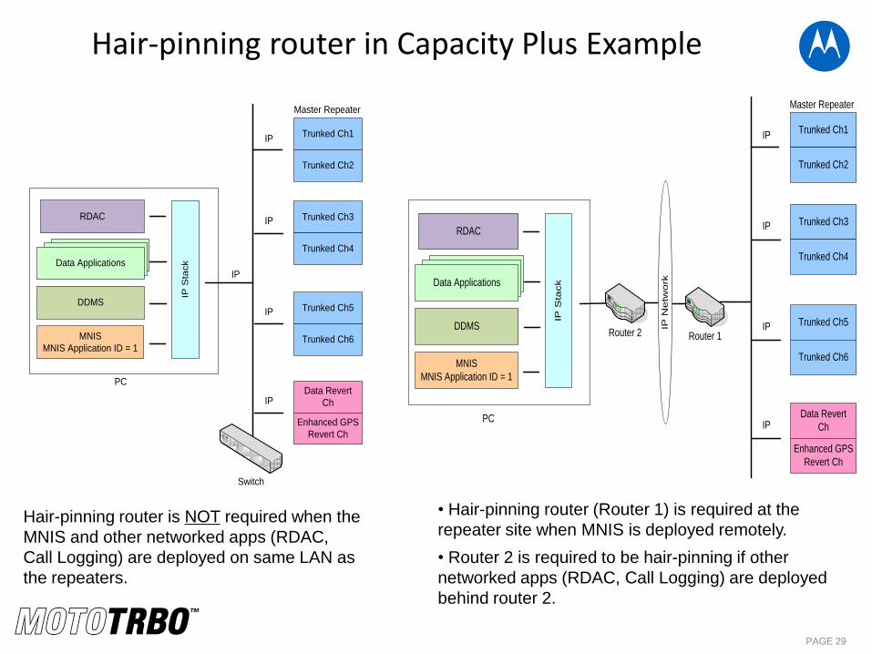
Hair-pinning router is NOT required when the
MNIS and other networked apps (RDAC,
Call Logging) are deployed on same LAN as
the repeaters.
• Hair-pinning router (Router 1) is required at the
repeater site when MNIS is deployed remotely.
• Router 2 is required to be hair-pinning if other
networked apps (RDAC, Call Logging) are deployed
behind router 2.
Trunked Ch1
Trunked Ch2
Trunked Ch3
Trunked Ch4
Trunked Ch5
Trunked Ch6
IP
IP
IP
Data Revert
Ch
Enhanced GPS
Revert Ch
IP
IP
Switch
Master Repeater
Data Applications
IP S
tack
DDMS
MNIS
MNIS Application ID = 1
RDAC
PC
Trunked Ch1
Trunked Ch2
Trunked Ch3
Trunked Ch4
Trunked Ch5
Trunked Ch6
IP
IP
IP
Data Revert
Ch
Enhanced GPS
Revert Ch
IP
Router 2 Router 1
Data Applications
PC
IP S
tack
DDMS
MNIS
MNIS Application ID = 1
RDAC
IP N
etw
ork
Master Repeater
PAGE 30
MNIS deployment with other apps
• MNIS, DDMS, RDAC, Radio Mgmt. can be deployed on the same PC – May require hair-pinning router in certain deployments
• MNIS and Control Station supporting voice dispatch can be deployed on the same PC
– As long as control station is not used for data there should be any problem
• Only one MNIS can be deployed per PC
• Only one DDMS can be deployed per PC

THANK YOU!
MOTOROLA, MOTO, MOTOROLA SOLUTIONS and the Stylized M Logo are trademarks or registered trademarks of Motorola Trademark Holdings, LLC and are used under license. All other trademarks are the property of their respective owners. © 2011 Motorola, Inc. All rights reserved.
MOTOROLA SOLUTIONS CONFIDENTIAL RESTRICTED
QUIZ
• List 3 advantages of MNIS over Control Station
•How many single site systems can one MNIS
support?
• Where and when shall we configure the ARS
Monitor ID?
PAGE 32
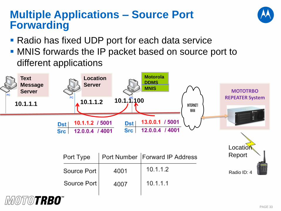
Multiple Applications – Source Port Forwarding
Radio has fixed UDP port for each data service
MNIS forwards the IP packet based on source port to
different applications
PAGE 33
MNIS
Location
Server
Motorola
DDMS
INTERNET/
WAN
Text
Message
Server
MOTOTRBO REPEATER System
10.1.1.2 10.1.1.1 10.1.1.100
Location
Report
Radio ID: 4
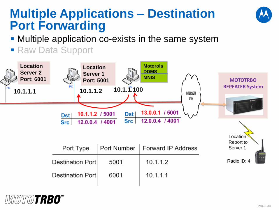
Multiple Applications – Destination Port Forwarding Multiple application co-exists in the same system
Raw Data Support
PAGE 34
MNIS
Location
Server 1
Port: 5001
Motorola
DDMS
INTERNET/
WAN
Location
Server 2
Port: 6001
MOTOTRBO REPEATER System
10.1.1.2 10.1.1.1 10.1.1.100
Location
Report to
Server 1
Radio ID: 4
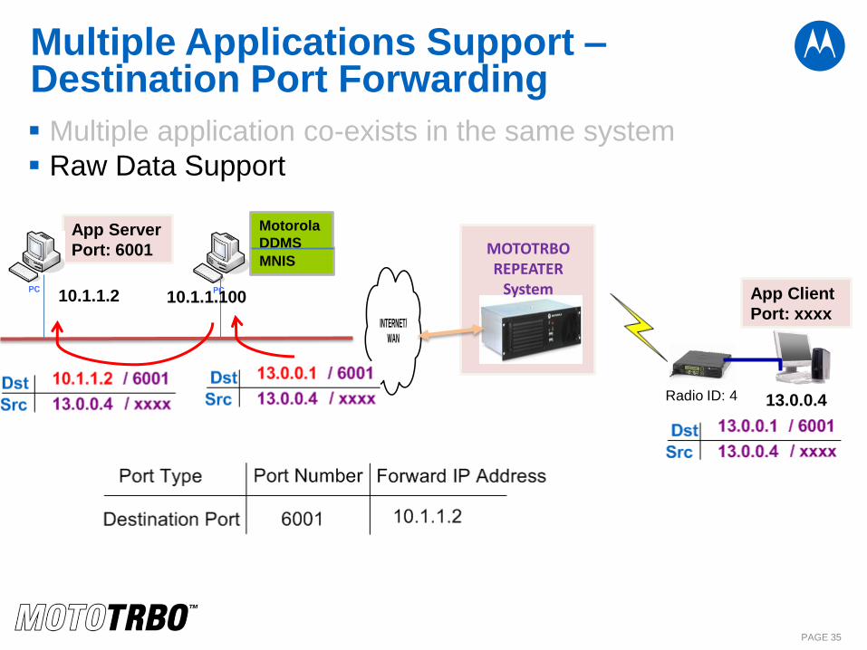
Multiple Applications Support – Destination Port Forwarding
Multiple application co-exists in the same system
Raw Data Support
PAGE 35
MNIS
App Server
Port: 6001
Motorola
DDMS
INTERNET/
WAN
MOTOTRBO REPEATER
System 10.1.1.2 10.1.1.100 App Client
Port: xxxx
13.0.0.4 Radio ID: 4

MNIS Based Deployment
PAGE 36
Advantages: Easy to set up
Support all the data services
Low Equipment Cost
IP connection into the radio system, does not have to be within RF
coverage
Support 16 talkgroup ranges
Use Local GPS Revert channel to increase the GPS capacity
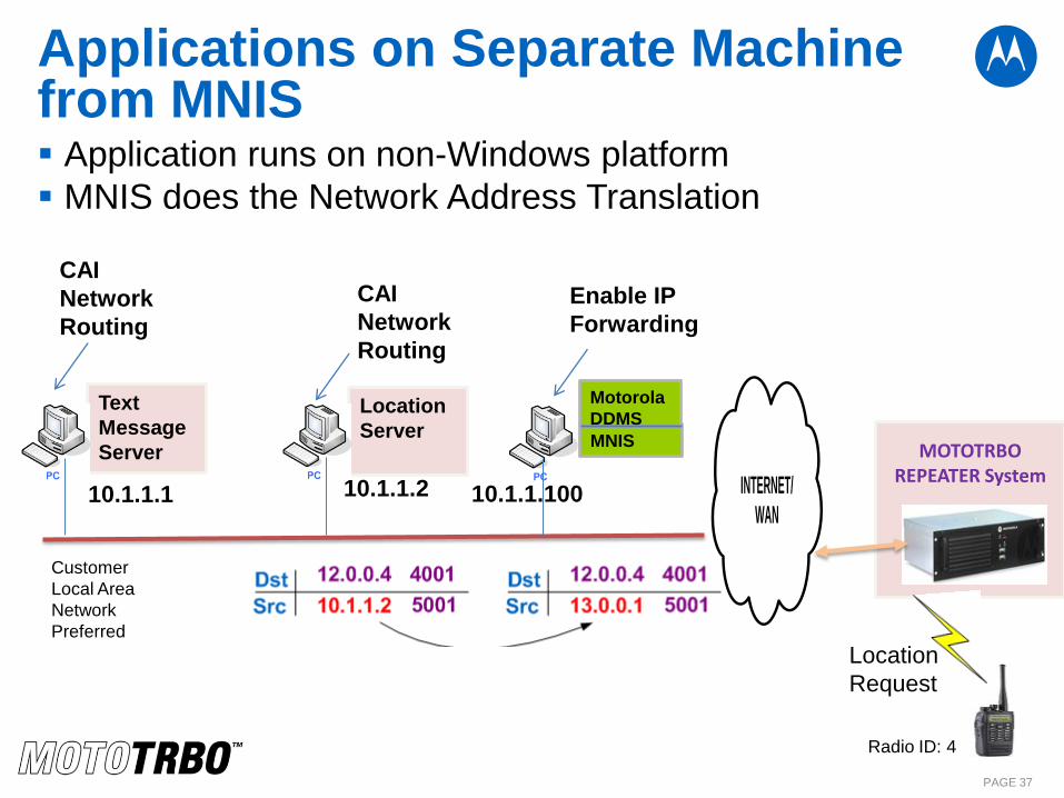
Applications on Separate Machine from MNIS Application runs on non-Windows platform
MNIS does the Network Address Translation
PAGE 37
MNIS
Location
Server
Motorola
DDMS
INTERNET/
WAN
Text
Message
Server
Customer
Local Area
Network
Preferred
MOTOTRBO REPEATER System
Enable IP
Forwarding
CAI
Network
Routing
CAI
Network
Routing
10.1.1.2 10.1.1.1 10.1.1.100
Radio ID: 4
Location
Request