Motor Vehicles UAZ PATRIOT, UAZ PICKUP, UAZ …2016...GOST 20306-90, when the motor vehicle total...
208
Ulyanovsk Automobile Plant LLC Motor Vehicles UAZ PATRIOT, UAZ PICKUP, UAZ CARGO Operation Manual OM 05808600.132-2011 Seventh Edition 2016
Transcript of Motor Vehicles UAZ PATRIOT, UAZ PICKUP, UAZ …2016...GOST 20306-90, when the motor vehicle total...

Ulyanovsk Automobile Plant LLC
Motor VehiclesUAZ PATRIOT,UAZ PICKUP,UAZ CARGO
Operation ManualOM 05808600.132-2011
Seventh Edition
2016

2
© Ulyanovsk Automobile Plant PJSC, 2016
WARNING!
The Operation Manual details are the necessary rules of motor vehicle operation and maintenance. Before getting started to operate a motor vehicle, please read carefully the Operation Manual and the vehicle log book. In particular, please read the sections “Safety requirements and warnings”, “New motor vehicle running-in” and “Engine start-up and stop” carefully. Improper operation can lead to injuries, malfunction in the motor vehicle and its assemblies and termination of the manu-facturing plant’s warranty liabilities. For safety and fault-free motor vehicle operation please observe the operation and maintenance instructions specified in the Manual.
Motor vehicle maintenance may be handled by one of the service stations recommended by the company that sold the motor vehicle. The service stations are provided with the necessary spare parts, special tools sets and instruments. All motor vehicle maintenance works are carried out by experienced specialists.
Due to continuous work on the improvement of the motor ve-hicle, the construction may include modifications that are not de-scribed in the present edition.
Have a safe trip!

3
CHAPTER 1. GENERAL INFORMATION Motor vehicle UAZ Patriot (UAZ-3163, UAZ-31638) — light, two-axle, off-road, 4х4 type, with an all-metal five-door bodyshell. Motor vehicle UAZ Pickup (UAZ-23632, UAZ-23638) — cargo-carrying (pickup), two-axle, off-road, 4х4 type, with a four-door cabin and a cargo compartment. Motor vehicle UAZ Cargo (UAZ-23602, UAZ-23602-01, UAZ-23602-02, UAZ-23608, UAZ-23608-01, UAZ-23608-02) — cargo-carrying, two-axle, off-road, 4х4 type, with a two-door cabin and a cargo bed, grocery and general purpose van. The motor vehicles are designed to transport passengers and cargo over all types of roads and terrain. The motor vehicles manufactured in ‘U’ as per Category 1 of GOST 15150 are meant for operation under ambient operating temperatures of minus 40 up to plus 40 °С, air relative humidity of up to 100% at plus 25 °С, air dust content of up to 1.0 g/m3 and wind speed of up to 20 m/s including in the regions located at altitudes of up to 3,000 m above sea level with a corresponding reduction of traction-dynamic characteristics and fuel efficiency. The motor vehicles manufactured in ‘T’ are meant for opera-tion under ambient operating temperatures of minus 10 up to plus 50 °С, air relative humidity of up to 100% at 35 °С under condi-tions specified above for the ‘U’—design motor vehicles. The ‘plus’ sign near the part (assembly) description means that this part (assembly) shall be installed into the motor vehicles depending on the configuration.
MOTOR VEHICLE MARKINGS
The motor vehicle nameplate (Fig. 1.1) is installed on the B-pillar (for UAZ CARGO — on the С-pillar) of the bodyshell side on the right-hand side of the motor vehicle. Vehicle identification number is marked on the nameplate (Fig. 1.1) and on the motor vehicle body, on the bottom windshield panel (Fig. 1.2).

4
Identification number (Fig. 1.2) consists of three parts: Part I — manufacturer international identification number, means: Х — geographical zone, where manufacturing plant is located; Т — country code; Т — manufacturing plant code. Descriptive part II — vehicle index. Indicating part III — year of vehicle manufacture and its order number.
Chassis identification number is stamped on the right-hand frame side member, at the rear (Fig. 1.3).
Fig. 1.1. Motor vehicle nameplate:I — Full Transport Vehicle Type Approval number (TVTA);II — Transport Vehicle identification number (VIN code);III — Transport Vehicle maximum permissible weight;IV — Maximum permissible weight of a transport vehicle with a trailer;V — Maximum permissible load on the front axle;VI — Maximum permissible load on the front back axle;VII — Engine model identification;VIII — Package code;IX — Variant execution code;X — Emission standard

5
Fig. 1.2. Location of transport vehicle identification number and a bodyshell number
Fig. 1.3. Location of chassis identification number
Engines ZMZ-40906 and ZMZ-51432’s identification number is stamped on the area located to the left of the crankcase, above engine front support fastening lug bosses (Fig. 1.4).
6
Fig. 1.4. Location of engine ZMZ-40906 identification numberI — descriptive part (VDS) consists of six characters. The first five characters (digits) represent the engine model code. If a model code contains fewer than five characters, a zero shall be entered in the free space at the end of the identification. A zero shall be entered in place of the sixth character. II — indicating part (VIS) consists of six characters. The first character (a letter or a digit) represents the conditional code of the year of vehicle manufacture, the second character (digit) is the conditional code of the engine manufacturing plant’s division, and the remaining characters (digits) are the order number of the engine since the start of the year of engine manufacture.

7
TEC
HN
ICA
L SP
ECIF
ICAT
ION
S
* D
imen
sion
s are
ave
rage
d, g
iven
for r
efer
ence
and
can
var
y de
pend
ing
on o
pera
tion
cond
ition
s, in
stal
led
tires
, the
ir co
nditi
on a
nd ti
re p
ress
ure,
mot
or v
ehic
le
load
, sus
pens
ion
cond
ition
, etc
.**
Mot
or v
ehic
le U
AZ-
2363
21 w
ith c
argo
com
partm
ent a
nd a
win
g re
ar d
oor b
elon
g to
N1G
veh
icle
cat
egor
y
Nam
eU
AZ
Patri
otU
AZ
Pick
upU
AZ
Car
goU
AZ-
3163
/UA
Z-23
6321
**U
AZ-
2363
2U
AZ-
2360
2 (0
1/02
)1
23
4G
ener
al d
ata
Mot
or v
ehic
le ty
peA
ll-te
rrai
n, tw
o-ax
le, 4
WD
axl
e co
nfigu
ratio
nVe
hicl
e di
men
sion
s *Sh
own
in F
ig. 1
.5-1
.11
Max
imum
bea
ring
capa
city
(in
clud
ing
driv
er a
nd p
asse
nger
s), k
g60
080
080
0 (6
65/5
75)
Seat
ing
capa
city
(inc
ludi
ng d
river
’s se
at)
55
2M
axim
um g
ross
ve
hicl
e w
eigh
t, kg
2,65
0/2,
670
2,86
02,
775
Gro
ss w
eigh
t dis
tribu
tion
by a
xles
, kg:
on
the
fron
t axl
e on
the
rear
axl
e1,
217/
1,11
41,
433/
1,55
61,
230
1,63
01,
090
(1,1
45/1
,132
)1,
685
(1,6
30/1
,643
)Ve
hicl
e cu
rb w
eigh
t (in
clud
ing
driv
er),
kg2,
125
2,13
52,
050
(2,1
85/2
,275
)C
urb
wei
ght d
istri
butio
n by
axl
es, k
g:
on th
e fr
ont a
xle
on th
e re
ar a
xle
1,15
097
51,
150
985
1,12
0 (1
,096
/1,0
97)
930
(1,0
89/1
,178
)

8
Fig.
1.5
. Mai
n di
men
sion
s of U
AZ
PATR
IOT
mot
or v
ehic
le w
ith g
ross
wei
ght
(dim
ensi
ons a
re sh
own
for r
efer
ence
)
* —
dep
endi
ng o
n pa
ckag
e
To th
e tow
ing
eye c
ente
rTo
the t
owin
g ey
e cen
ter

9
Fig.
1.6
. Mai
n di
men
sion
s of U
AZ
PIC
KU
P m
otor
veh
icle
with
gro
ss w
eigh
t (d
imen
sion
s are
giv
en fo
r ref
eren
ce)
* —
dim
ensi
ons w
ith to
nnea
u co
ver
** —
dep
endi
ng o
n pa
ckag
e
To th
e tow
ing
eye c
ente
rTo
the t
owin
g ey
e cen
ter

10
Fig.
1.7
. Mai
n di
men
sion
s of U
AZ
PIC
KU
P m
otor
veh
icle
with
a lo
ad b
ox c
over
w
ith g
ross
wei
ght (
dim
ensi
ons
are
show
n fo
r ref
eren
ce)
* —
dep
endi
ng o
n pa
ckag
e
To th
e tow
ing
eye c
ente
rTo
the t
owin
g ey
e cen
ter

11
Fig.
1.8
. Mai
n di
men
sion
s of U
AZ
PIC
KU
P m
otor
veh
icle
with
a lo
ad b
ox to
p bo
w
(dim
ensi
ons a
re sh
own
for r
efer
ence
)
* —
dep
endi
ng o
n pa
ckag
e
To th
e tow
ing
eye c
ente
rTo
the t
owin
g ey
e cen
ter

12
Fig.
1.9
. Mai
n di
men
sion
s of U
AZ
PIC
KU
P m
otor
veh
icle
with
a lo
ad b
ox sh
elte
r w
ith g
ross
wei
ght (
dim
ensi
ons a
re sh
own
for r
efer
ence
)
* —
dep
endi
ng o
n pa
ckag
e
To th
e tow
ing
eye c
ente
rTo
the t
owin
g ey
e cen
ter
13
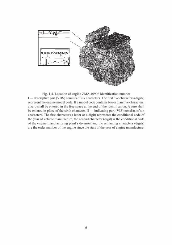
Fig.
1.1
0. M
ain
dim
ensi
ons o
f UA
Z C
AR
GO
m
otor
veh
icle
with
gro
ss w
eigh
t (d
imen
sion
s are
show
n fo
r ref
eren
ce)
To th
e tow
ing
eye c
ente
rTo
the t
owin
g ey
e cen
ter

14
Fig.
1.1
1. M
ain
dim
ensi
ons o
f UA
Z C
AR
GO
m
otor
veh
icle
with
a fo
od v
an o
r a g
ener
al
purp
ose
van
with
gro
ss w
eigh
t (d
imen
sion
s are
show
n fo
r ref
eren
ce)
* —
dim
ensi
on fo
r a fo
od v
an
To th
e tow
ing
eye c
ente
rTo
the t
owin
g ey
e cen
ter

15
* W
ith a
tent
and
van
s**
In c
ase
of a
bal
l-typ
e to
w-h
itch
12
34
Max
imum
spee
d, k
m/h
r15
014
013
5 (1
25*)
Fuel
con
sum
ptio
n at
driv
ing
with
co
nsta
nt sp
eed
90 k
m/h
, l/1
00km
11.5
1212
(13.
5*)
Fuel
con
sum
ptio
n at
driv
ing
with
con
stan
t spe
ed o
f 120
km
/h, l
/100
km
15.5
15.6
—
Not
e. F
uel c
onsu
mpt
ion
valu
e is
use
d to
det
erm
ine
the
mot
or v
ehic
le te
chni
cal c
ondi
tion
and
shal
l not
be
rega
rded
as t
he o
pera
tion
stan
dard
. Fu
el c
onsu
mpt
ion
mea
surin
g ac
cura
cy is
onl
y en
sure
d in
spec
ial t
estin
g co
nditi
ons a
nd in
stric
t com
plia
nce
with
the
requ
irem
ents
of
GO
ST 2
0306
-90,
whe
n th
e m
otor
veh
icle
tota
l mile
age
reac
hes 9
,000
–10,
000
km.
Gro
ss w
eigh
t of a
tow
ed tr
aile
r, kg
, max
.:eq
uipp
ed w
ith b
rake
sw
ithou
t bra
kes
1,50
0**
750*
*M
inim
um tu
rnin
g ra
dius
on
the
cent
erlin
e of
the
fron
t out
er
(as t
o th
e tu
rnin
g ce
nter
) w
heel
trac
e, m
, max
.6.
557.
08M
inim
um o
uter
turn
ing
radi
us
as to
the
fron
t bum
per p
oint
, th
e fa
rthes
t fro
m th
e tu
rnin
g ce
nter
, m
, max
.6.
87.
35

16
12
34
Max
imum
clim
b co
vere
d by
a m
otor
ve
hicl
e of
gro
ss w
eigh
t, de
gree
(%)
31 (6
0)M
axim
um fo
rdin
g de
pth,
m0.
5E
ngin
eM
odel
ZMZ-
4090
6Ty
pefo
ur-c
ycle
with
spar
k-pl
ug ig
nitio
nC
ylin
der n
umbe
rFo
urC
ylin
der a
rran
gem
ent
In-li
ne, v
ertic
alIg
nitio
n se
quen
ce1-
3-4-
2C
ylin
der d
iam
eter
, mm
95.5
Pist
on st
roke
, mm
94En
gine
dis
plac
emen
t, cm
32,
693
Com
pres
sion
ratio
9.1
Min
imum
cra
nksh
aft r
pm a
t idl
e, m
in-1
800–
900
Max
imum
torq
ue, N
•m (k
gf•m
) as
per
Rul
es 8
5 U
NEC
E (G
OST
R 4
1.85
)21
7.0
(22.
1) a
t 3,9
00 m
in-1
Max
imum
cap
acity
, kW
(h.p
.):
as p
er R
ules
85
UN
ECE
(GO
ST R
41.
85)
99.0
(134
.6) a
t 4,6
00 m
in-1
17
* Fo
r mot
or v
ehic
les c
onfig
urat
ions
of c
lass
5 e
mis
sion
stan
dard
app
ly si
mila
r fue
l of c
lass
5, t
ype
III a
nd K
5**
For
mot
or v
ehic
les w
ith th
e tra
nsfe
r box
pro
duce
d by
LLC
“U
AZ”
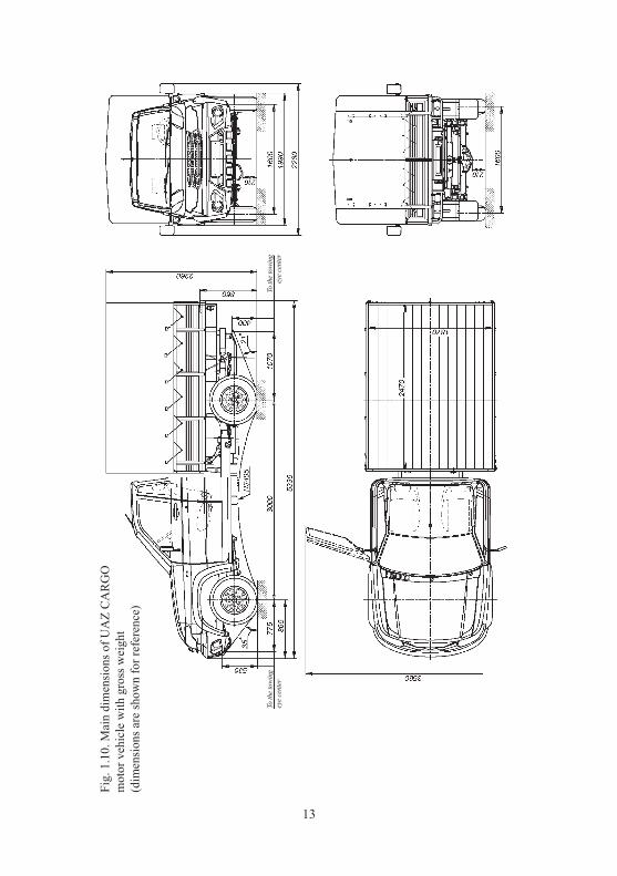
12
34
Lubr
icat
ion
syst
emC
ombi
ned:
forc
e-fe
ed a
nd c
entri
fuga
lC
ase
vent
ilatio
nC
lose
dFu
el fe
ed sy
stem
Dis
tribu
ted
fuel
inje
ctio
n w
ith e
lect
roni
c co
ntro
lFu
elU
nlea
ded
gaso
line
‘Reg
ulat
or-9
2’ (A
I-92
-4) G
OST
R 5
1105
*, A
I-92
-K4
GO
ST 3
2513
Allo
wed
: Pre
miu
m E
uro-
95 ty
pe II
(AI-
95-4
) and
Sup
er E
uro-
98 ty
pe II
(AI-
98-4
) G
OST
R 5
1866
, AI-
95-K
4, A
I-98
-K4
GO
ST32
513*
.C
oolin
g sy
stem
Liqu
id, c
lose
d w
ith fo
rced
-circ
ulat
ion
Tran
smis
sion
Clu
tch:
clut
ch ty
pedr
ive
type
Dry
sing
le d
isk
Hyd
raul
icG
ear b
ox:
gear
box
type
cont
rol t
ype
Mec
hani
cal,
five-
spee
d co
ntro
l typ
eM
echa
nica
lTr
ansf
er c
ase:
type
of t
rans
fer c
ase
cont
rol t
ype
pow
er ta
ke-o
ff**
With
fron
t axl
e dr
ive
deco
uplin
gTw
o-st
age
by ‘D
ymos
’U
AZ
PJSC
With
ele
ctric
con
trol
mec
hani
cPo
ssib
le fo
r the
driv
e (a
t veh
icle
driv
ing
and
park
ing)
of s
peci
al p
acks
, ins
talle
d in
the
body
shel
l, th
e po
wer
take
-off
box
is in
stal
led
by th
e C
usto
mer
. Per
mis
sibl
e po
wer
take
-off
—
40%
. Ins
talla
tion
of th
e po
wer
take
-off
shal
l be
agre
ed u
pon
with
UA
Z, P
JSC
18
* —
dep
endi
ng o
n pa
ckag
e
12
34
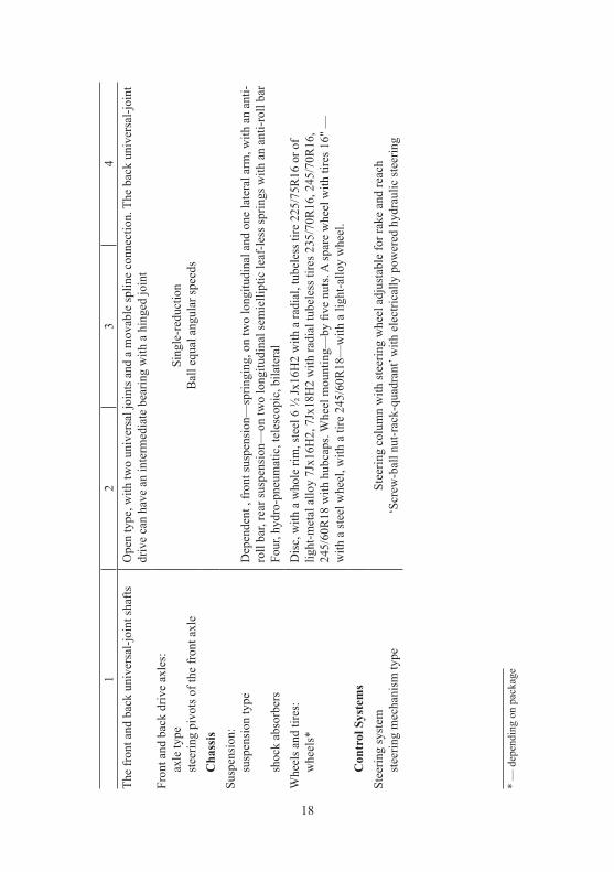
The
fron
t and
bac
k un
iver
sal-j
oint
shaf
tsO
pen
type
, with
two
univ
ersa
l joi
nts a
nd a
mov
able
splin
e co
nnec
tion.
The
bac
k un
iver
sal-j
oint
dr
ive
can
have
an
inte
rmed
iate
bea
ring
with
a h
inge
d jo
int
Fron
t and
bac
k dr
ive
axle
s:ax
le ty
pest
eerin
g pi
vots
of t
he fr
ont a
xle
Sing
le-r
educ
tion
Bal
l equ
al a
ngul
ar sp
eeds
Cha
ssis
Susp
ensi
on:
susp
ensi
on ty
pe
shoc
k ab
sorb
ers
Dep
ende
nt ,
fron
t sus
pens
ion—
sprin
ging
, on
two
long
itudi
nal a
nd o
ne la
tera
l arm
, with
an
anti-
roll
bar,
rear
susp
ensi
on—
on tw
o lo
ngitu
dina
l sem
ielli
ptic
leaf
-less
sprin
gs w
ith a
n an
ti-ro
ll ba
rFo
ur, h
ydro
-pne
umat
ic, t
eles
copi
c, b
ilate
ral
Whe
els a
nd ti
res:
whe
els*
Dis
c, w
ith a
who
le ri
m, s
teel
6 ½
Jх16
H2
with
a ra
dial
, tub
eles
s tire
225
/75R
16 o
r of
light
-met
al a
lloy
7Jx1
6H2,
7Jx
18H
2 w
ith ra
dial
tube
less
tire
s 235
/70R
16, 2
45/7
0R16
, 24
5/60
R18
with
hub
caps
. Whe
el m
ount
ing—
by fi
ve n
uts.
A sp
are
whe
el w
ith ti
res 1
6" —
w
ith a
stee
l whe
el, w
ith a
tire
245
/60R
18—
with
a li
ght-a
lloy
whe
el.
Con
trol
Sys
tem
sSt
eerin
g sy
stem
stee
ring
mec
hani
sm ty
peSt
eerin
g co
lum
n w
ith st
eerin
g w
heel
adj
usta
ble
for r
ake
and
reac
h ‘S
crew
-bal
l nut
-rac
k-qu
adra
nt’ w
ith e
lect
rical
ly p
ower
ed h
ydra
ulic
stee
ring

19
* Fo
r win
ter p
acka
ge
12
34
Bra
kes
peda
l bra
ke ty
peW
ith fr
ont d
isc
brak
es a
nd b
ack
drum
bra
kes
wor
king
bra
ke d
rive
type
Hyd
raul
ic d
oubl
e-ci
rcui
t typ
e w
ith d
iago
nal s
epar
atio
n w
ith A
BS,
with
the
vehi
cle
elec
troni
c co
ntro
l sys
tem
(ESP
) or w
ithou
t ESP
or w
ith c
ircui
ts se
para
tion
by a
xles
with
pre
ssur
e co
ntro
ller w
ithou
t AB
S w
ith v
accu
m b
oost
erA
ccor
ding
to th
e pa
ckag
e, m
otor
veh
icle
s can
be
equi
pped
with
AB
S, E
SP (i
n th
is c
ase
ther
e is
no
mec
hani
cal p
ress
ure
cont
rolle
r). C
ircui
t spl
ittin
g is
dia
gona
l (pr
imar
y —
righ
t han
d fr
ont a
nd
left
hand
bac
k w
heel
, sec
onda
ry —
left
hand
fron
t and
righ
t han
d ba
ck w
heel
).pa
rkin
g br
ake
type
Whe
eled
, com
bine
d w
ith re
ar b
rake
s or d
rum
and
tran
smis
sion
park
ing
brak
e ac
tuat
or ty
peM
echa
nica
lE
lect
ric
equi
pmen
tW
iring
syst
emSi
ngle
-wire
, neg
ativ
e po
le c
onne
cted
to th
e m
otor
veh
icle
‘gro
und’
Grid
vol
tage
(rat
ed),
V12
Alte
rnat
or11
.203
.640
F. (
‘Pra
mo-
Iskr
a’) 1
4V, 8
0A; 5
122.
3771
(‘Pr
amo-
Elec
tro’)
14V
, 80A
fo
r mot
or v
ehic
les w
ith a
ir-co
nditi
oner
— 5
12.3
771-
30 (‘
Pram
o-El
ectro
’) 1
4V, 1
20 A
; 32
112.
3771
Bor
isov
city
‘BAT
E’ 1
4V, 1
10A
Bat
tery
6ST-
66A
3 (6
ST75
A)*

20
* Fo
r UA
Z Pa
triot
mot
or v
ehic
les
12
34
Spar
k pl
ugs
АU
14D
VR
M G
OST
Р53
842,
DR
17Y
C-F
f. B
RIS
KSt
art m
otor
11.1
31.5
68 1
2V, 1
.9kW
(‘Pr
amo-
Iskr
a’);
5112
.370
8 12
V, 1
.2 k
W (B
ATE)
Engi
ne c
ontro
l uni
tB
OSC
H 0
261
S07
321
Igni
tion
star
ter s
witc
hW
ith a
n an
ti-th
eft d
evic
e an
d a
star
ter r
e-en
gage
men
t loc
kA
udio
ele
ctric
sign
alTw
o si
gnal
s — to
ne, h
orn
Win
dshi
eld
wip
erEl
ectri
cally
driv
en, w
ith tw
o br
ushe
s, th
ree-
mod
e, w
ith p
ause
adj
ustm
ent
in in
term
itten
t ope
ratio
n m
ode
* Ta
il ga
te w
indo
w w
iper
Elec
trica
lly d
riven
, with
one
bru
shW
ashe
rEl
ectri
cally
driv
en, f
or w
inds
hiel
d an
d re
ar w
indo
wPo
wer
win
dow
sR
emot
e co
ntro
lled
Elec
trica
l int
erlo
ckin
g sy
stem
Des
igne
d fo
r sim
ulta
neou
s int
erlo
ckin
g of
all
mot
or v
ehic
le’s
doo
r loc
ks*
Safe
par
king
syst
em+
Des
igne
d to
war
n a
driv
er o
f obs
truct
ions
, loc
ated
out
of d
river
’s si
ght,
whe
n m
otor
veh
icle
mov
ing
in re
vers
e w
ith m
ax. s
peed
of 5
km
/hA
djus
ting
valu
esD
eflec
tion
of fa
n be
lt an
d po
wer
stee
ring
pum
p at
forc
e of
4 k
gf, m
m5–
8D
eflec
tion
of g
ener
ator
bel
t and
coo
ling
syst
em p
ump
at fo
rce
of 8
kgf
, mm
14–1
5

21
12
34
Gap
bet
wee
n sp
ark
plug
s ele
ctro
des,
mm
0.7+0
,15
Bra
ke p
edal
free
pla
y, m
m5–
8Fr
ont w
heel
toe-
in0°
4'–0
°10'
Larg
est t
urni
ng a
ngle
fron
t inn
er w
heel
, de
g.31
–32
Stee
ring
syst
em to
tal p
lay
(ste
erin
g w
heel
an
gle
from
the
posi
tion
corr
espo
ndin
g to
th
e be
ginn
ing
of st
eera
ble
whe
els t
urni
ng
in o
ne d
irect
ion
to th
e st
eerin
g w
heel
po
sitio
n co
rres
pond
ing
to th
e be
ginn
ing
of st
eera
ble
whe
els t
urni
ng in
the
oppo
site
di
rect
ion)
, deg
., m
ax.
20W
heel
and
tire
in a
ssem
bly
unba
lanc
e,
g∙cm
, max
.10
00Ti
re a
ir pr
essu
re,
MPa
(kgf
/cm
2 ):in
the
fron
t whe
els:
225/
75R
1623
5/70
R16
245/
70R
1624
5/60
R18
0.20
(2.0
)0.
19 (1
.9)
0.17
(1.7
)0.
18 (1
.8)
0.20
(2.0
)0.
19 (1
.9)
0.17
(1.7
)–
0.19
(1.9
)– – –

22
12
34
in th
e re
ar w
heel
s:22
5/75
R16
235/
70R
1624
5/70
R16
245/
60R
18
0.24
(2.4
)0.
22 (2
.2)
0.21
(2.1
)0.
20 (2
.0)
0.27
(2.7
)0.
25 (2
.5)
0.24
(2.4
)–
0.28
(2.8
)– – –
Fuel
ling
data
(litr
es)
Fuel
tank
69±1
Engi
ne c
oolin
g sy
stem
14.0
Engi
ne lu
bric
atio
n sy
stem
6.5
Bra
ke h
ydra
ulic
driv
e sy
stem
0.6
Gea
rbox
hou
sing
2.5
Tran
sfer
hou
sing
:‘D
ymos
’U
AZ
PJSC
1.8
0.8
Fina
l driv
e ho
usin
g:fr
ont a
xle
back
axl
e1.
51.
4Po
wer
hyd
raul
ic st
eerin
g sy
stem
1.36
5C
lutc
h hy
drau
lic d
rive
syst
em0.
18W
inds
hiel
d w
ashe
r res
ervo
ir5

23
CHAPTER 2. SAFETY REQUIREMENTS AND WARNINGS
SAFETY REQUIREMENTS
1. When operating the motor vehicle, it is necessary to observe road traffic regulations and safety requirements, keep the motor vehicle in good repair, and carry out timely maintenance and cor-rect any possible malfunctions, in order to avoid injury to yourself and others. 2. A driver is responsible for the passengers. Therefore, a driver must ensure that his or her passengers observe all safety rules. Be specially careful when children are in the motor vehicle. Do not leave children unattended in the motor vehicle. 3. It is prohibited to switch off the ignition, and remove the key from the ignition starter switch, when driving the motor vehicle. 4. When leaving the motor vehicle, do not leave door keys and ignition keys inside. 5. Before opening a door, ensure that it will not be a hindrance for other road users. Before closing a door, make sure it will not catch someone or something. It is prohibited to drive the motor vehicle with any door being opened. 6. Do not adjust the tilt angle of the steering column when driving the motor vehicle. 7. Do not adjust the driver seat when driving the motor vehicle. 8. Observe the requirements of safe power window usage. Do not allow children to use power windows. 9. It is prohibited to use lamps that are not required by design. 10. Seatbelts are an efficient means of driver and passenger protection against drastic consequences of traffic accidents. Use of seatbelts is mandatory! 11. Worn, damaged, underinflated or overpressured tires, warped wheels or wheel unfastening can cause a car crash.

24
12. Note, that while the engine is off, the force required for steering and motor vehicle braking increases significantly. 13. If the steering system or brake system does not work prop-erly, further motor vehicle driving or towing with a tow-rope is not allowed. In this case, you should use two-wheel vehicle towing or a tow truck service. 14. It is prohibited to drive with the engine switched off, as brake efficiency is lost. 15. It is strictly prohibited to disassemble shock absorbers. 16. It is prohibited to start and warm-up the engine in a confined space, which does not have proper ventilation. 17. Do not subject motor vehicle’s aggregates to open flames. 18. Keep the engine clean (engine fouling can cause fire). 19. Make sure that the fuel tank plug is closed tightly, and that there are no leaks from fuel lines. 20. The catalytic converter operating temperature is 400–800 °С. The motor vehicle shall not be operated, if no protective screen is installed on the catalytic converter. During motor vehicle motion and in standstill, keep an eye on the exhaust system, ensuring that it has no contact with inflammable materials (e.g., dry grass). 21. When handling low-freezing liquid or fuel or brake fluid, please observe the following rules: – avoid any operations as a result of which these liquids or fumes can enter the mouth cavity; – do not let liquid dry out on the skin, immediately wash it off with soap and warm water; – flush spilled liquid with water, ventilate the room; – remove clothing contaminated with liquid, dry it outdoors and wash it; – moisten petrol deposits with kerosene when scraping, in order to prevent poisonous particles from entering the respiratory system; – when handling fuel, observe fire safety rules. 22. When the motor vehicle stops, it should be braked with the parking brake.

25
23. When handling electrolytic solution, take special precau-tions. In order to prevent poisoning and chemical burns, please observe the following rules: – strictly observe the safety requirements, specified in the accumulator battery manual; – keep electrolytic solution or fumes from entering the mouth cavity, respiratory system or eyes, as it is very dangerous; – avoid any operation, as a result of which the electrolytic solution can come into contact with the skin. If the solution comes into contact with the skin, carefully wipe off electrolytic solution with cotton wool and immediately rinse remaining traces from the skin with a 5% solution of ammonia and sodium carbonate; – spilled electrolytic solution must be collected with a special rubber bulb or a hydrometer and flushed with water, and the room must be ventilated; – to charge the battery, it must be removed from the motor vehicle and filler plugs must be unscrewed; – the battery must be charged in a well-ventilated room. Elec-trolyte fume accumulation is dangerous to health and explosive. 24. Do not wash the motor vehicle while the engine is running. When washing the motor vehicle, avoid spraying water directly onto electric equipment articles, electronic devices, sensors and detachable connections in the engine compartment. Monitor the condition of the protective cases of electronic modules and sen-sors and detachable connections. In case of moisture penetration, detachable connections must be blown off with compressed air and processed with a water repellent vehicular preparation, to protect terminals against oxidation. 25. A jacking apparatus installed improperly can cause serious injury or motor vehicle damage. It is strictly prohibited to carry out works under the motor vehicle supported only by a jacking apparatus. 26. It is prohibited to drive downhill with a gear switched off in the gear box or the transfer case, or with the clutch switched off. 27. For UAZ Pickup motor vehicles, the weight of cargo haul-ing in the load box must not exceed 425 kg.

26
28. For UAZ Pickup and UAZ Cargo motor vehicles, it is rec-ommended to distribute the cargo, or to place the cargo closer to the cab. 29. Maximum permitted weight of the cargo hauling in the trunk compartment (including trunk compartment weight), when installing it on the UAZ Patriot motor vehicle’s bows, shall not exceed 50 kg. In case of the motor vehicle without bows, cargo hauling on the roofing is not allowed. 30. When carrying out maintenance and routine repairs of the motor vehicle, the following requirements shall be met: – before starting work, check tools and accessories for normal operation, arrange work clothing: button the cuffs tuck in the clothing, so that there are no hanging ends, tuck hair under a closed-body hair cover; – when carrying out any works, the motor vehicle must be securely braked; – do not carry out maintenance operation and repair of the motor vehicle with engine on, except for specific works that require engine start according to the procedure, with that, take special care; – avoid bringing hands, parts of clothing and tools dangerously close to operating drive belts, pulleys, etc.; – the fuel supply system is under pressure, when the engine is running, after the fuel pump, therefore, it is prohibited to carry out maintenance (e.g., tightening joints) repair of subsystems with the engine on, or immediately after its shutdown; – take due care when opening the radiator cap of the engine cooling system, to avoid scalding; – before arc welding operations, fuel tanks shall be removed and the battery “-” terminal shall be disconnected; – observe fire safety rules. 31. Waste oils and specialty liquids shall be collected and sent for recycling or disposal. 32. Several safety requirements are detailed in the respective chapters of the Manual.
27
WARNINGS
1. During the initial operating period, all recommendations specified in chapter “New motor vehicle running-in” shall be strictly observed. 2. Switching on of the engine malfunction lamp does not mean that the engine must be shutdown immediately. However, in case of a malfunction caused by ignition failures (engine wobble or jerking when driving the motor vehicle), the motor vehicle shall be immediately (max. in 0.5 min.) stopped, and the engine shall be shut off in order to prevent breakdown of catalytic converter. 3. Do not start driving motor vehicle with a cold engine. Avoid high crankshaft speeds after starting a cold engine. In order to prevent any difficulties when starting the engine, follow the instructions in chapter “Engine start”. 4. In case of abnormal noises and knocks in a running engine, find out the cause of their occurrence, the motor vehicle must not be operated until the malfunction is corrected. 4.1. After starting a cold engine, the hydraulic valve may knock, that should disappear in the course of engine warm-up to the coolant temperature of 80–90 °С, but not more than in 30 minutes after reaching the specified temperature. If knock persists, it is necessary to check oil feed to the hydraulic pushers, or to replace faulty hydraulic pushers. 5. For fail-safe operation, and to prevent accelerator pedal breakdown, it is recommended to: – not apply excessive loads on the pedal lever, after end of operating stroke; – avoid impact, lateral and other loads that do not correspond to the pedal operating stroke. 6. Engage reverse in the gear box and down-shift in the transfer case only when the motor vehicle completely stops. 7. Always shut-off the engine while fuelling the vehicle. 8. Before fuelling the motor vehicle, the heater-temperature booster (if available) shall be switched off. 9. Do not overfill the fuel tank.

28
10. When driving over dry hard roads, the front axle shall be disengaged. Avoid front axle engagement when driving the motor vehicle with small turning radii. 11. In case of malfunction of any brake circuit, the brake pedal stroke increases and brake efficiency decreases. 12. Be careful when carrying out any operation with the motor vehicle hood opened, as the electric fan can switch on (irrespective of whether engine is on or off), on command of the Engine Control Unit. 13. ESP is an auxiliary system of the motor vehicle. Motor vehicle equipped with ESP cannot exceed its physical capacity. Do not rely on ESP only. Observe usual precautions while driving (including adequate speed choice, depending on the road situation). 14. Safe parking system is optional equipment that facilitates motor vehicle driving, but does not drive the motor vehicle itself, therefore the manufacturing plant is not responsible for any pos-sible damages when driving in reverse. 15. It is prohibited to remove metal segments with the engine on, or to check sparking charge “to ground”. 16. Avoid spilling acids, soda solutions, brake fluid, antifreeze and fuel on the painted surface of the bodyshell, wheels and rubber parts. 17. In order to prevent clouding of the headlight assembly lenses and scratches on them: – dry foreign materials on the external surface of the lens, the lenses must be cleaned off only by pre-moistening them with plenty of water; – do not apply aggressive chemical substances (petrol, acetone, solvents, etc.), aggressive detergents or sharp objects to clean headlight assembly lenses; – to prevent overheating of the headlight assembly lenses, do not switch on heavily polluted headlight assemblies. Do not switch on headlight assemblies covered with any object.
29
18. Before washing the motor vehicle in an automatic washer and entering low-ceiling rooms, always remove the antenna, otherwise it can be damaged. To remove the antenna, unscrew it counter-clockwise. To re-install, screw it in clockwise. 19. When folding the two-passenger section of the back triple seat, make sure that the middle seatbelt is not fastened. Monitor the condition of the plastic limiting clip of the middle seatbelt. 20. Using the heater fan at above average to maximum opera-tion modes, under pouring rain conditions, can result in soaking of the filter for air entering the interior and dripping ingression of moisture at the feet of the front passenger. 21. Avoid impact loads on the motor vehicle chassis. In case of strong blows to the front wheels, carefully inspect the wheels, all parts of the front axle, steering links, steering gear and engine oil pan, and correct any detected defects. 22. Differential lock (depending on the configuration) installs rigid connection between the left and the right wheels, excluding their separate slipping, which in some cases improves the motor vehicle off-road capability, but worsens its controllability and stabil-ity, as well as overloads the transmission parts. For efficient, and at the same time safe utilization of the differential lock, consider and perform the following: – do not use the differential lock on dry and paved roads, as this may lead to increased transmission loads, accelerated tire wear and vehicle maneuverability deterioration; – driving the motor vehicle on roads with low coefficient of adhesion (sleet) with differential lock switched on will provoke the loss of adhesion of the wheels to the road and skidding of the rear axle with violation of stability. Be careful switching on the differential lock on the motor vehicle equipped with ABS, as ABS is not able to function correctly when the lock is switched on, therefore ABS switches off forcibly. When the ABS switches off, the motor vehicle tendency to skid upon breaking on a slip-pery road sharply increases. After switching off of the differential block, the ABS switches on automatically;

30
– while moving at a turn with the differential lock switched on, the motor vehicle lacks turnability and has a tendency to drift to the outer turning circle, especially on roads with low coefficient of adhesion; – switch on the lock only with the engine on, after the vehicle stops. Do not try to switch on the lock while the wheels are slip-ping, as this will lead to shock load and breakdown of parts; – switch on the lock only if engaging the front axle is not enough to overcome the hindrance, and only after the front axle is engaged; – do not switch off the lock while moving at a turn. After the lock switching off signal is received, the locking clutch may remain switched on for some time. The clutch will switch off after gas-pedal release, for instance, during gear shift. After the hindrance is overcome, and the differential lock is switched off (either manually or automatically) make sure that the clutch has unblocked the differential (while moving at turns, neither wheels slippage nor knocks in the transmission are detected, and the controllability of the motor vehicle does not differ from usual). The switching on of the differential lock does not necessarily increase the off-road capability of the motor vehicle. For instance, while driving on soft (waterlogged) ground, the switched on dif-ferential lock can lead to turf disruption, and the “burying” of the wheels. Switching on the lock is especially efficient at diagonal lifting of the vehicle’s wheels or at huge difference in the adhesion of the wheels on the right and on the left.
23. To prevent excessive loads on the axle differential, avoid long-term slipping of one of the wheels. 24. When operating the motor vehicle in the cold season (ambi-ent temperature of 0 °С and lower) it is recommended to apply a cold weather radiator cowl cover. To prevent freezing through of the pipe crankcase ventilation system, at ambient temperature below (-15 °С), it is necessary to disconnect the resonator-type hose from the air filter, turn the filter tightly counter-clockwise (the inlet air filter is directed backwards and downwards).
31
At ambient temperature below minus 30 °С, it is recommended to operate the motor vehicle with the front axle continuously engaged. 25. If the duration of motor vehicle parking exceeds 12 hours at ambient temperature below minus 30 °С, it is recommended to store the accumulator battery in a warm room. 26. To prevent oil overheating and power steering pump mal-function, it is not recommended to hold the steering wheel in an extreme position for more than 5 s. 27. Use only recommended lubricants and specialty liquids. 28. Knocks in the transfer case are possible at the moment of front axle engagement. 29. When switching on the A/C and with the transmission control lever in the neutral position, pings in the gear box synchronizer rings are possible. These pings can increase with high gear actua-tion and with the front wheels turned to the limit. 30. The opened lift gate or the tailgate can block visibility of the back lighting system of your motor vehicle for other road users. Before opening the lift gate of UAZ Patriot or the tailgate of UAZ Cargo motor vehicle, install a breakdown triangle on the road, as per GOST R 41.27-99. 31. Tightening torques of the main threaded joints are shown in Annex 2 of the Manual. 32. Long-term, fault-free and safe operation of the motor vehicle depends on accurate compliance with the requirements of the Manual and the vehicle log book. 33. The plant continuously improves the design of its motor vehicles, hence the latest engineering changes that do not affect operation, may not be reflected in this Manual edition.

32
CHAPTER 3. CONTROL ELEMENTS, MOTOR VEHICLE INTERIOR
AND BODYSHELL EQUIPMENT Layout of the control elements and the driver’s seat equipment is shown in Figs. 3.1, 3.2: 1 — steering column with steering wheel, with key blocks, ignition switch, multi-function switches and steering column tilt angle and length control lever. 2 — instrument cluster (Fig. 3.5). 3 — steering wheel lining with sound signal switch and built-in driver’s air-bag module. 4 — air temperature sensor. 5 — solar radiation sensor. 6+ — head unit of multimedia system. 7 — device switches. Set of switches depends on the motor vehicle package:
Windshield electrical heating switch. Briefly press-ing the switch key with ignition ON sends a signal to the heating time relay, which actuates the heating
element of the windscreen. Windshield electrical heating will be switched off in 12±2 min. automatically or when the switch key is pressed again or when key is off.
Mirror heating switch (for motor vehicles without rear screen de-mist);
Rear screen de-mist and mirror heating switch;
Alarm signal switch. For triple switch of the alarm signal short press the switch button twice;
ESP turn-off switch;
Off-road mode switch;

33
Fig.
3.1
. Con
trol e
lem
ents
and
driv
er’s
seat
equ
ipm
ent
for m
otor
veh
icle
s UA
Z PA
TRIO
T an
d U
AZ
PIC
KU
P (f
or it
em d
escr
iptio
n se
e th
e re
leva
nt te
xt)

34
Fig.
3.2
. Con
trols
, and
pas
seng
er se
at e
quip
men
t fo
r UA
Z C
AR
GO
mot
or v
ehic
le
(for
item
des
crip
tion,
see
the
rele
vant
text
)
35
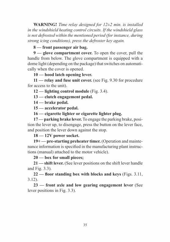
WARNING! Time relay designed for 12±2 min. is installed in the windshield heating control circuits. If the windshield glass is not defrosted within the mentioned period (for instance, during strong icing conditions), press the defroster key again. 8 — front passenger air bag. 9 — glove compartment cover. To open the cover, pull the handle from below. The glove compartment is equipped with a dome light (depending on the package) that switches on automati-cally when the cover is opened. 10 — hood latch opening lever. 11 — relay and fuse unit cover. (see Fig. 9.30 for procedure for access to the unit). 12 — lighting control module (Fig. 3.4). 13 — clutch engagement pedal. 14 — brake pedal. 15 — accelerator pedal. 16 — cigarette lighter or cigarette lighter plug. 17 — parking brake lever. To engage the parking brake, posi-tion the lever up, to disengage, press the button on the lever face, and position the lever down against the stop. 18 — 12V power socket. 19+ — pre-starting preheater timer. (Operation and mainte-nance information is specified in the manufacturing plant instruc-tions (manual) attached to the motor vehicle). 20 — box for small pieces; 21 — shift lever. (See lever positions on the shift lever handle and Fig. 3.3). 22 — floor standing box with blocks and keys (Figs. 3.11, 3.12). 23 — front axle and low gearing engagement lever (See lever positions in Fig. 3.3).
36
LIGHTING CONTROL MODULE
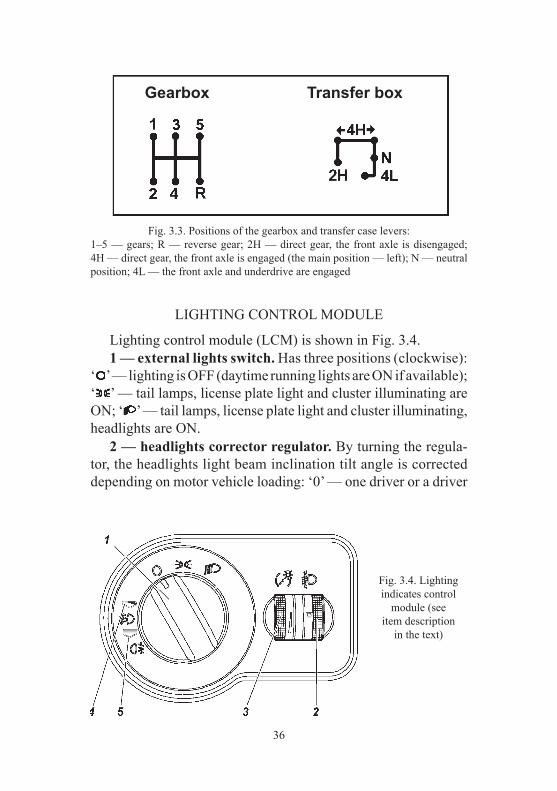
Lighting control module (LCM) is shown in Fig. 3.4. 1 — external lights switch. Has three positions (clockwise): ‘ ’ — lighting is OFF (daytime running lights are ON if available); ‘ ’ — tail lamps, license plate light and cluster illuminating are ON; ‘ ’ — tail lamps, license plate light and cluster illuminating, headlights are ON. 2 — headlights corrector regulator. By turning the regula-tor, the headlights light beam inclination tilt angle is corrected depending on motor vehicle loading: ‘0’ — one driver or a driver
Fig. 3.4. Lighting indicates control
module (see item description
in the text)
Fig. 3.3. Positions of the gearbox and transfer case levers:1–5 — gears; R — reverse gear; 2Н — direct gear, the front axle is disengaged; 4Н — direct gear, the front axle is engaged (the main position — left); N — neutral position; 4L — the front axle and underdrive are engaged
Gearbox Transfer box

37
with a passenger on the front seat; the point between ‘0’ and ‘1’ — all seats in the interior are occupied (5 persons); ‘1’ — all seats in the interior are occupied plus cargo in the luggage compartment up to the permissible load on the rear axle; the point between ‘1’ and ‘2’ — a driver plus cargo, well-distributed in the interior and the luggage compartment up to the permissible load on the rear axle. In case of other load options (not exceeding gross weight) the position is selected so that road illumination with dimmed beam is within normal limits and opposing motor vehicle drivers are not blinded by light. 3 — cluster dimmer. Light intensity of control units is changed by turning the regulator. 4 — fog lights indicator. Fog lights are switched on by pulling the external lights switch handle out to the first fixed position (the handle should be in positions ‘ ’ or ‘ ’. Green signal device lights up in the cluster. 5 — rear fog lamps indicator. Rear fog lamps are switched on by pulling the external lights switch handle out to the second fixed position. If the fog lights are not installed on the motor vehicle, the rear fog lamps are switched on at pulling the external lights switch handle out to the fixed position only in position ‘ ’ (headlights are on). Yellow signal device lights up in the cluster.
CLUSTER
Cluster is shown in Fig. 3.5. Green and blue signal devices inform the driver of the normal operation of the switched on system. Orange signal devices warn a driver of the need to take measures to ensure the motor vehicle’s continued normal operation. Red signal devices warns the driver of an emergency packs operation. Motor vehicle operation with continuously lighted (at least one) red signal device is not allowed.
38
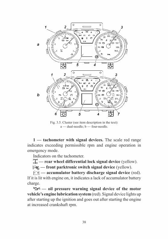
1 — tachometer with signal devices. The scale red range indicates exceeding permissible rpm and engine operation in emergency mode. Indicators on the tachometer. — rear wheel differential lock signal device (yellow). — front parktronic switch signal device (yellow). — accumulator battery discharge signal device (red). If it is lit with engine on, it indicates a lack of accumulator battery charge. — oil pressure warning signal device of the motor vehicle’s engine lubrication system (red). Signal device lights up after starting up the ignition and goes out after starting the engine at increased crankshaft rpm.
Fig. 3.5. Cluster (see item description in the text):a — dual-needle; b — four-needle.
a
b

39
— complex microprocessor engine control system malfunction signal device of the engine control system elements, which affects the exhaust gas toxicity (yellow). It lights up when starting up the ignition and goes out after starting the engine. When the signal device switches on, it indicates a malfunc-tion of the engine components or the exhaust system, which affect the exhaust gas toxicity level. When the signal device switches on, if it is not accompanied by significant deteriora-tion of riding qualities, driving is permitted at low speed to the nearest authorized service station of UAZ, PJSC, to carry out diagnostic works. Prolonged operation with the malfunction signal device switched on can lead to malfunction of the elements of the engine control system. When switching on, the signal device starts blinking with fre-quency of 5 Hz in case of engine control unit malfunction, and also in case of immobilizer malfunction and using of an unregistered code key (see section ‘Electronic anti-theft device’). — speed limiter signal device (green). — off-road mode turning on signal device (green). — signal device of abnormal coolant overheating (red). 2 — signal device box: — left direction indicator and hazard light ON signal device (green). — right direction indicator and hazard light ON signal device (green). — axle front engagement signal device (green). It lights up after starting up the ignition and should go out if this mode is not ON. It lights up when engaging the front axle at any gear of the transfer case. For the motor vehicle with the transfer case of UAZ, PJSC, the signal device is not used. — front axle and underdrive ‘4L’ engagement signal device (green). It lights up after starting up the ignition and should go out if this mode is not ON. For the motor vehicle with the transfer case of UAZ, PJSC, the signal device is not used.

40
— transfer case malfunction signal device (yellow). It lights up after starting up the ignition and should go out if the system is in normal condition. If the indicator is still ON, the all-wheel control system should be checked at the nearest authorized service station. For the motor vehicle with the transfer case of UAZ, PJSC, the signal device is not used. — tail lamps ON signal device (green). — distance lights ON signal device (blue). — font fog lights ON signal device (green). — rear fog lamp ON signal device (yellow). — door ajar signal device (red). — security alarm system signal device (yellow). — immobilizer ON signal device (yellow). — 4-wheel drive ON (for the transfer case by UAZ, PJSC). 3 — speedometer with signal devices. Signal devices on the speedometer:
— cruise-control signal device (white/green). — brake ABS malfunction signal device (ABS) (yellow). — park brake ON signal device (red). — unbuckled seatbelt signal device (red). — air bags control system malfunction signal device (yellow). — service brake system and EBD malfunction signal device (red). — function or malfunction of ESP signal device (yellow). — ESP switch off signal device (yellow).
41
— low fuel level signal device (yellow). It lights up when less than 9 l of fuel is left in the right tank. 4 — trip computer switch. Switching over is performed by pressing and turning the switch clockwise/counter-clockwise. 5 — LCD-display (depending on package) displays the fol-lowing functions of the trip computer: – coolant temperature in the engine (for dual needle cluster); – fuel level in the fuel tank (for dual needle cluster); – motor vehicle power supply voltage; – motor vehicle total and daily mileage. Daily mileage counter reset is performed by long (over 2 s) pressing the cluster switch; – time of day (in 24-h format). To set the clocks, the ‘Clocks setting’ mode should be switched on in the trip computer. By long pressing the cluster switch (over 2 s), the setting mode is activated. Hours/minutes values can be set by turning the switch clockwise/counter-clockwise. Switching over between hours/minutes settings is performed by short (less than 1 s) pressing the cluster switch; – ambient temperature (depending on the package); – date (in ‘XX month’ format). To set the date, the ‘Date setting’ mode should be switched on in the trip computer. By long press-ing the cluster switch or button ‘Set/Reset’ on the understeering switch (more than 2 s), the setting mode is activated. Day, month and year can be set by turning the switch clockwise/counter-clockwise. Switching over between day/month/year/minutes settings is performed by short (less than 1 s) pressing the cluster switch or button ‘Set/Reset’ on the understeering switch; – instantaneous fuel economy (l/100 km); – average fuel consumption (l/100 km); – fuel distance (in km); – current motor vehicle speed; – average motor vehicle speed.

42
6 — coolant temperature indicator. Engine operation with the indicator pointer in the red range is not allowed. Range of values from 50 °С to 130 °С. Division value 10 °С. 7 — fuel level indicator.
LIGHT ALARM SWITCH
Direction indicators and headlights switch has the following positions (Fig. 3.6) I — neutral position. Direction indicators are OFF, low beam is ON, if forward lighting is switched on by the external light switch; II — right direction indicators are ON (three blinks). Unstable position. III — right direction indicators are ON (stable position). IV — left direction indicators are ON (three blinks). Unstable position. V — left direction indicators are ON (stable position) VI — pull, headlights high beam flash. Short-time high beam switch regardless of vehicle light switch position. Unstable position. VII — (push) distance light is ON, if forward lighting is switched on by the vehicle light switch (stable position);
Fig. 3.6. Understeering switch left lever shift scheme at direction indicators and headlightss control (see items names in the relevant text)

43
Control button 1 and ring 2 of the left understeering switch is used for the trip computer control (unstable position when turning) (Fig. 3.7). Searching for the trip computer functions is performed similar to the trip computer switch 4 (Fig. 3.5).
Fig. 3.7. Trip computer control elements on the understeering
switch left lever:1 — button; 2 — switch ring.
WINDSHIELD WIPERS AND WASHER SWITCH
Windshield wipers and washers operate only when the igni-tion is on. The windshield wiper and washer switch lever has the following positions (Fig. 3.8). I — neutral position. The windshield wiper and washer are OFF. II — windshield wiper intermittent mode is ON. Stable position. Spacing interval of the windshield wiper intermittent mode depends on the spacing interval regulator position 1 (Fig. 3.9). III — windsсreen wiper constant mode (low speed) is ON (stable position). IV — windshield wiper constant mode (high speed) is ON. Stable position. V — Short-time operation of electric windshield wiper blades is provided (one cycle of the wipers motion). Unstable position of the switch. VI — (pull) windshield wiper and washer are ON. VII — rear screen wiper is on. Stable position. The intermittant operation of the tailgate rear windoe washer is activated by the rotary switch.
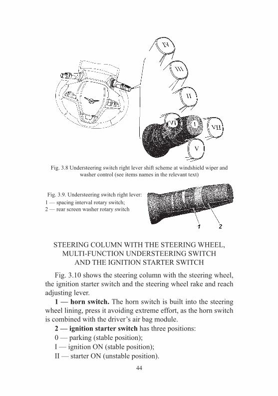
44
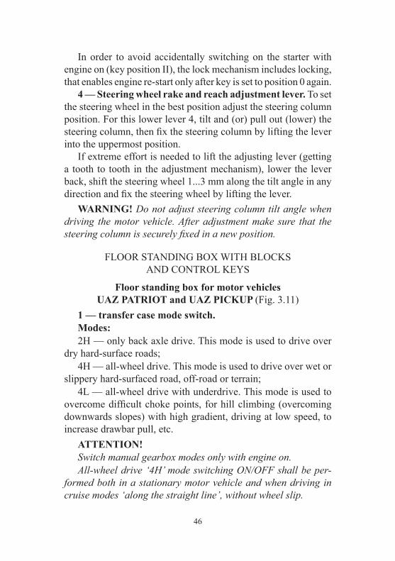
Fig. 3.9. Understeering switch right lever:1 — spacing interval rotary switch;2 — rear screen washer rotary switch
STEERING COLUMN WITH THE STEERING WHEEL, MULTI-FUNCTION UNDERSTEERING SWITCH
AND THE IGNITION STARTER SWITCH
Fig. 3.10 shows the steering column with the steering wheel, the ignition starter switch and the steering wheel rake and reach adjusting lever. 1 — horn switch. The horn switch is built into the steering wheel lining, press it avoiding extreme effort, as the horn switch is combined with the driver’s air bag module. 2 — ignition starter switch has three positions: 0 — parking (stable position); I — ignition ON (stable position); II — starter ON (unstable position).
Fig. 3.8 Understeering switch right lever shift scheme at windshield wiper and washer control (see items names in the relevant text)

45
WARNING! It is prohibited to cut off IGN and remove the key from the ignition starter switch while driving the motor vehicle. Engine stoppage will lead to braking capacity reduction, and upon removing the key the steering system shaft becomes blocked by an anti-hijack device and the motor vehicle can no longer be controlled. 3 — ignition and door key. Three keys are attached to the motor vehicle, each key is designed to unlock door locks and to start up the ignition. The transponder, an electronic chip that saves the unique identification number, is embedded in the motor vehicle key bow. The immobilizer blocks the engine start without code pre-reading from the transponder thus ensuring additional protection against unauthorized use. The key is removed from the lock only in position 0, in which the locking device mechanism actuates and locks the steering system shaft. To lock the steering system when parked, set the key to posi-tion 0, remove it and turn the steering wheel in any direction until it clicks, which indicates that locking device catch has matched with the groove of the steering wheel shaft stop sleeve. When unlocking the steering system, insert the key to the igni-tion switch and, swaying the steering wheel to right and left, turn the key clockwise to position I.
Fig. 3.10. Steering column with the steering wheel, the steering wheel rake and reach adjusting lever and the ignition starter switch
(items names see in the relevant text).
46
In order to avoid accidentally switching on the starter with engine on (key position II), the lock mechanism includes locking, that enables engine re-start only after key is set to position 0 again. 4 — Steering wheel rake and reach adjustment lever. To set the steering wheel in the best position adjust the steering column position. For this lower lever 4, tilt and (or) pull out (lower) the steering column, then fix the steering column by lifting the lever into the uppermost position. If extreme effort is needed to lift the adjusting lever (getting a tooth to tooth in the adjustment mechanism), lower the lever back, shift the steering wheel 1...3 mm along the tilt angle in any direction and fix the steering wheel by lifting the lever. WARNING! Do not adjust steering column tilt angle when driving the motor vehicle. After adjustment make sure that the steering column is securely fixed in a new position.
FLOOR STANDING BOX WITH BLOCKS AND CONTROL KEYS
Floor standing box for motor vehicles UAZ PATRIOT and UAZ PICKUP (Fig. 3.11)
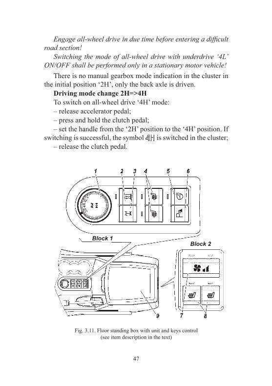
1 — transfer case mode switch. Modes: 2Н — only back axle drive. This mode is used to drive over dry hard-surface roads; 4Н — all-wheel drive. This mode is used to drive over wet or slippery hard-surfaced road, off-road or terrain; 4L — all-wheel drive with underdrive. This mode is used to overcome difficult choke points, for hill climbing (overcoming downwards slopes) with high gradient, driving at low speed, to increase drawbar pull, etc. ATTENTION! Switch manual gearbox modes only with engine on. All-wheel drive ‘4Н’ mode switching ON/OFF shall be per-formed both in a stationary motor vehicle and when driving in cruise modes ‘along the straight line’, without wheel slip.
47
Fig. 3.11. Floor standing box with unit and keys control (see item description in the text)
Engage all-wheel drive in due time before entering a difficult road section! Switching the mode of all-wheel drive with underdrive ‘4L’ ON/OFF shall be performed only in a stationary motor vehicle! There is no manual gearbox mode indication in the cluster in the initial position ‘2H’, only the back axle is driven. Driving mode change 2Н=>4Н To switch on all-wheel drive ‘4H’ mode: – release accelerator pedal; – press and hold the clutch pedal; – set the handle from the ‘2Н’ position to the ‘4Н’ position. If switching is successful, the symbol is switched in the cluster; – release the clutch pedal.
Block 1Block 2

48
If: – efforts are made to switch all-wheel drive mode ON at the moment of significant back wheel slip against the front wheel; – the motor vehicle is driven with a pressure difference in the front and back wheels exceeding the pressure difference specified in the Manual; – immediately before switching on turning with minimum pos-sible radius has been performed, or an effort to switch on is made immediately when turning; – in other exceptional cases, when front wheel and back wheel drives will have different rpms at the moment of engagement all-wheel drive; system switching over to the emergency mode is possible, of which the simultaneous switching on of signal devices is an indicator , , and in the cluster. With that only the back wheel drive remains active. In this case, to switch the ‘4H’ mode, it is necessary to set the switch to the ‘2H’ position and the ‘4H’ mode should be switched on again. Driving mode change 4Н=>2Н To switch all-wheel drive mode OFF (engagement of back axle drive ‘2H’) it is necessary to: – release accelerator pedal; – press and hold the clutch pedal; – set the handle from the ‘4Н’ position to the ‘2Н’ position. If switching over is successful, the symbol is switched off in the cluster; – release the clutch pedal. Driving mode change 4Н=>4L To switch on the mode of all-wheel drive with underdrive 4L (beforehand the all-wheel drive ‘4H’ mode must be switched on), it is necessary to: – stop the motor vehicle; – press and hold the clutch pedal; – set the switch handle from the ‘4Н’ position through the ‘4L’ position to the unstable position ‘•’ and hold it until the signal device in the cluster switches on;
49
– when the signal device switches on in the cluster, release the switch handle (the switch handle self-resets to the ‘4L’ position); – start driving, smoothly releasing the clutch pedal. Driving mode change 4L=>4H To switch on the mode of all-wheel drive with underdrive it is necessary to: – stop the motor vehicle; – press and hold the clutch pedal; – set the switch handle from the ‘4L’ position to the ‘4H’ position; – when the signal device switches on in the cluster, start driving, having smoothly released the clutch pedal. 2+ — preheater starting switch . 3+ — rear wheel differential lock switch . To switch the lock on press and hold button 3 (Fig. 3.11) until the rear axle differential lock signal device turns on in the cluster. On motor vehicles UAZ PATRIOT and UAZ PICKUP (with transfer box ‘Dymos’) preliminary shift the transfer box in 4L mode, on motor vehicles UAZ CARGO (with transfer box ‘UAZ’) — in 4x4 mode. After the lock is on ABS is automati-cally turns off, as a result ABS malfunction signal device lights up (Fig. 3.5), LED-display of the cluster shows the following messages: ‘Wheel differential lock is off’, ‘Hill start assistance is off’, ‘ABS is off’. Manual switching off of the lock is possible at any time by repeated pushing and holding of button 3 (Fig. 3.11) until the rear axle differential lock signal device is turned off . Besides, the lock is turned off automatically after the key is removed or if the speed exceeds 30 km/h, and on motor vehicles UAZ PATRIOT and UAZ PICKUP (with transfer box ‘Dymos’) also when mode 4L is off. After the lock is turned off signal devices
go off in the cluster too (Fig. 3.5).

50
Diagnostics of the lock control system is maintained by the engine control unit after the lock is turned on. If any malfunc-tion is detected the engine malfunction signal device lights up in the cluster (Fig. 3.5). Fault codes reading is conducted with diagnostic scanning tester for UAZ motor vehicles diagnostics. 4+ — back seat heater switches . By short pressing the switch, the heating of the respective seat switches on and the signal device lights up. Seat heating and the signal device are switched off when the switch is pressed again or when the key is removed. 5+ — steering wheel heater switch . The steering wheel heater is activated by pushing the button, the signal device located above the button lights up. To turn off the steering wheel heater repeatedly push the switch or remove the key. 6+ — the front parktronic turn-off button. The ON signal device is in the cluster. Turn on/off the front parktronic by successive pushing of the button. When the key is removed the control unit stores the latest position of the parktronic. 7+ — auxiliary heater speed control switch. Low speed of the auxiliary heater electric motor is switched on by short pressing the switch, at which point the left signal device above the switch lights up. When the switch is short pressed again, the high speed auxiliary electric heater motor is switched on, additionally the right signal device lights up. By short pressing the switch or when the key is removed, the auxiliary heater and signal devices are switched off. 8+ — back seat heater switches. By short pressing the switch, the heating of the respective seat switches on and the signal device lights up. Seat heating and the signal device are switched off when the switch is pressed again or when the key is removed. 9 — glove box.

51
Fig. 3.12. Floor standing box with unit and keys control (see item description in the text)
Floor standing box for motor vehicle UAZ CARGO (Fig. 3.12)
1+ — rear wheel differentiallock switch. 2+ — front seat heater switches. 3 — glove box.
MOTOR VEHICLE’S ELECTRONIC ANTI-THEFT SYSTEM WITH THE ENGINE CONTROL UNIT МЕ 17.9.71
The anti-theft system set includes three ignition keys, in whose bows the transponders are embedded. The keys are equal in terms of their functional capabilities. The system allows eight ignition keys to be registered. The prerequisite for system operation is the registration of three ignition keys. The system can be in the ‘neutral’, ‘taught’ and ‘key upgrading’ states with respect to ignition key registration. ‘Neutral’ state — after replacing the engine control unit at a service station, the system carries out automatic registration of the ignition keys, for this purpose the ignition should be started up by each key one by one.
52
Motor vehicle engine start is not possible until three keys are registered automatically and the system state changes to ‘taught’. ‘Taught’ state — three keys are registered successfully. ‘Key upgrading’ state — after the procedure of switching over to this state, the system registers (re-registers) the required number of the ignition keys. When starting up the ignition without successful key registra-tion and successful key code recognition the engine start is not possible. With regard to prevention of unauthorized motor vehicle use the system can be in the ‘ON’ and ‘OFF’ states. ‘ON’ state — the immobilizer locks engine start. The immobi-lizer turning-on signal device is continuously switched ON. The system switches over to this state in the following cases: – if the engine is not started for 25 s after starting up the igni-tion and successful key code recognition; – if after starting up the ignition the key code is not recognized (the system will store the trouble code, which can be read out using a diagnostic tester); – if the system is in the ‘neutral’ state and key registration is not carried out; – if the system is in the ‘taught’ state and an unregistered key is used; – if the system is in the ‘key upgrading’ state and key registra-tion (re-registration) is not carried out; – in 25 s after starting up the ignition; – in 25 s in case of engine stop and there are no efforts to re-start the engine; – after power failure. ‘OFF’ state — the immobilizer does not prevent engine start. The immobilizer ON signal device is OFF. The system switches over to this state (disarming) after starting up the ignition provided that the key code is recognized successfully. The ignition key (transponder) can be in the ‘initial’, ‘registered’ and ‘faulty’ states.

53
‘Initial’ state — the ignition key, handed over by the manufac-turer, which is not registered in the system. ‘Registered’ state — the ignition key, registered in the specific system. After successful recognition of the key, engine start is possible. ‘Faulty’ state — the ignition key, whose code was not recognized by the system at starting up the ignition. Motor vehicle engine start is not possible. WARNING! To register (re-register) the keys, any two keys that were previously registered during the last session should be used. Take all necessary measures to prevent key loss. It is not recommended to start the engine using a key registered in this system that is in the same bunch with other keys, both registered and unregistered. After starting up the ignition (Fig. 3.5), the immobilizer turning-on signal device lights up for 1.5 s in the test mode. Then the signal device initiates the following state of the anti-theft system until engine starts: – the system is in the ‘ON’ state or the key registration procedure is not completed — the signal device is continuously ON; – the system is in ‘OFF’ state or the key registration procedure is completed — the signal device is OFF; – when performing the key registration procedure, the signal device switches on 5 times for a period of 1 s (0.5 s — OFF / 0.5 s — ON); – the system is in the ‘neutral’ state — the signal device switches on 3 times for a period of 3 s (1.5 s — OFF / 1.5 s — ON). – the system is in the ‘key teaching’ state — the signal device switches on 4 times for a period of 3 s (1.5 s — OFF / 1.5 s — ON). Keys registration. Only ignition keys that are in ‘initial’ and ‘registered’ states (previously registered in the system) are subject to the registration. Keys registered in other systems cannot be re-registered in this system. The registration is only possible using any two keys that are registered in the previous key registration session.
54
Key registration with the system in the ‘taught’ state is used to ensure that the motor vehicle owner have additional available ignition keys (without deleting codes registered in the previous ignition key registration session). In order to register a key it is necessary to carry out the fol-lowing operations: – start up the ignition using one of the registered keys, turning it into position I (Fig. 3.10) of the ignition starter switch; – make sure that ignition is started up, key code is recognized (the immobilizer turning-on signal device is OFF); – 10 seconds after starting up, shut ignition, turning the key into the 0 position (Fig. 3.10); – For 10 s start up the ignition using another registered key, make sure that the ignition is started up, the key is recognized; – 10 s after starting up, shut ignition. The immobilizer turning-on signal device starts blinking, the system is ON; – For 20 s (signal device blinking time) start up the ignition using the key to be registered. Registration is completed if in 5 s the signal device goes out. If the signal device is lit continuously (without blinking), the key registration is considered uncompleted. If a larger number of keys should be taught, repeat the key registration procedure. WARNING! Switching on the start motor or violation of the specified time intervals or switching OFF the power supply system prevent logging on the key registration procedure, and if the system is already in the procedure, interrupt all further key registration operations. Key re-registration is used if at least one key is lost, and to register additional keys (by deleting codes of the previously reg-istered keys). For this purpose it is necessary to switch the system over to the ‘key upgrading’ state and re-register keys: – start up the ignition using one of the registered keys, turning it into position I (Fig. 3.10) of the ignition starter switch;

55
– make sure that ignition is started up, key code is recognized (the immobilizer turning-on signal device is OFF); – 10 seconds after starting up, shut ignition, turning the key into the 0 position (Fig. 3.10); – for 10 s start up the ignition using another registered key, make sure that the ignition is started up, the key is recognized; – 10 s after starting up, shut ignition. The immobilizer turning-on signal device starts blinking, the system is ON; – for 20 s (signal device blinking time) press the accelerator pedal. When the system recognizes full pressing of the accelerator pedal, the immobilizer turning-on signal device is OFF; – keep the accelerator pedal pressed for 60 s. After that the immobilizer turning-on signal device starts blinking; – for 20 s (signal device blinking time) start up the ignition using the key to be registered (not the first and not the second registered key). The immobilizer turning-on signal device is continuously lit. Release the accelerator pedal. Key registration is completed if in 2 s the signal device goes out. If the signal device starts blinking, the key registration is considered incomplete and the registration process is interrupted; – 10 s after starting up the ignition, shut ignition and remove the key from the ignition starter switch. For registration of additional keys start the ignition up with the key to be registered within 20 s return to the previous operation; – to finish the key registration, start ignition using the second (from the start of the procedure) registered key. The immobilizer turning-on signal device continues blinking for 2 s and then switches OFF; – 10 s after starting up the ignition, shut ignition and remove the key from the ignition starter switch; – for 20 s (signal device blinking time), start up the ignition using the first (from the start of the procedure) registered key. The signal device switches OFF. After that, the system deletes all key codes registered during the previous teaching session and registers all keys used in the current registration procedure (the first, the second registered keys and additional keys). Key registration is completed if the signal device switches ON and goes out in 2 s.
56
If key registration is unsuccessful, the immobilizer turning-on signal device will continue blinking and the system will be locked until the ignition is started up using any of the registered keys. WARNING! Switching on the start motor or violation of the specified time intervals or switching OFF the power supply system prevent logging on the key re-registration procedure, and if the system is already in the procedure, interrupt all further key registration operations.
POWER PACK CONTROL SYSTEM+
The system includes the control unit (CU), the driver side door module (DSDM) and two keys with a remote control panel (RCP). Description of the electronic anti-theft system, key registration and system operation is shown above in the chapter ‘Motor vehicle electronic anti-theft system...’. WARNING. Using the RCP in the absence of obstruction, it is possible to control the electrical interlocking system in the front, from the left and right side of the motor vehicle at a distance of 10 m, at rear — at distance of about 6 m. To prevent theft, use remote control in close proximity to the motor vehicle. The control unit records, saves and displays the detected mal-functions of the electrical interlocking system upon request of the diagnostic tester that has the respective software. Do not subject the RCP to the action of increased electromag-netic emission. To prevent malfunction, protect the RCP against detergents, fuels, oils and lubricants, water. The electrical interlocking system allows up to four RCPs to be taught. When working with the electrical interlocking system the RCPs are equal in terms of functional capabilities. The teaching and educable control panel shall be separated from the shared bunch of taught and non-taught RCP and ignition keys with transponders when teaching the RCP. Take measures to prevent RCP's loss.

57
It is prohibited to operate the system if there is a possibility of the ingression of corrosive liquids, acids, water, oil and petrol in the CU, DSDM and RCP. System functions: – central locking and unlocking with the key; – central door locking and unlocking from the inside of interior; – door locking and unlocking from the RCP depending on the motor vehicle package; – side door window lifting and lowering control; – outside rear view mirror position adjustment control; – interior lighting control (polite lighting) depending on the motor vehicle package; – intrusion alarm system; – motor vehicle search in an unlighted parking place; – ‘Panic’ signalling and prompt alarm; – system trouble diagnosis through the motor vehicle data link connector.
Operation procedure with the control systemDoor locks locking and armed mode
switching on using the RCP To lock door locks and switch armed mode ON it is necessary to short press button 3 (Fig. 3.13) on the RCP. All side door locks and the lock of the T/gate are locked, the system switches over to the armed mode that is indicated by a single blink of the T/signals and a slow blinking of the signal device system in the cluster . If any door, the cowl or the T/gate are opened when switching armed mode on, the T/signals blink three times and a single horn is given. In order to include the opened areas into the security zone they must be closed.
Door locks unlocking and armed mode switching off using the RCP
To unlock all door locks and the T/gate lock and switch armed mode OFF it is necessary to short press button 2 on the RCP. Switching armed mode OFF is accompanied by a double blink

58
Fig. 3.13. Key with remote control panel:
1 — emission confirmation and control panel battery discharge indicator; 2 — lock unlocking and alarm switching off button; 3 — lock locking and alarm switching on button; 4 — horn button
of the T/signals and interior lighting switching ON. If violations of the security zone for the whole security period were detected (Alarm actuated), a single horn will be given in addition to T/signal blinking. If after door unlocking and switching armed mode OFF none of side doors or the T/gate are opened and the ignition is not started up, in 30 seconds all doors will be automatically locked again and the system will automatically switch over to the armed mode. The possibility of automatically switching over to the armed mode with door locking is indicated by frequent blinking of the system’s signal device in the cluster .
Unlocking the door locks from the RCP with side door window lowering
Unlocking of all side doors locks and the T/gate lock with automatic side door window opening is carried out by pressing the respective RCP button and holding it pressed till the window starts moving (about 2–3 seconds). The system carries out opera-tions specified in the above mentioned items to unlock door locks and then carries out automatic moving of side door window to open — firstly front windows, then back windows. Every window movement is stopped automatically when reach-ing the limit stop in the extreme position or all window movement is stopped simultaneously by pressing any RCP button. Movement of side door windows toward closing when locking the door locks through the system is not to be carried out in order to comply with the requirements of the international safety rules.

59
Locking/unlocking locks from outside the motor vehicle without switching on armed mode
To lock the door locks without switching to armed mode, it is necessary to lock by turning the key in the driver side door key hole clockwise. The locks of all side doors and the T/gate lock are locked without armed mode switching on. This type of locking is not accompanied by T/signal blinking. Door locks are unlocked the same way, the only difference is turning the key counter-clockwise.
Fast driver side door lock unlocking The system can be switched over to the fast driver side door unlocking mode when, by single pressing button 2 of the RCP or turning the key in the driver side door key hole, only the driver side door is unlocked and, when pressing button 2 on the RCP or button 2 (Fig. 3.14) of the DSDM again, all other side doors and the T/gate are unlocked. To switch on/off the fast unlocking mode it is necessary to press button 2 of the DSDM max. 1 second after starting up the ignition and hold it pressed (for at least 3 seconds) until the characteristic sound of the door locks triggered to open. If subsequently the system should be switched over to the standard unlocking mode it is necessary to repeat the above mentioned procedure.
Searching for a motor vehicle in an unlighted parking place
By single pressing and holding button 4 of the RCP (Fig. 3.8) the system blinks with T/signals two times, gives one horn and switches interior lighting ON for about 25 s.
Remotely switching alarm system (‘Panic’) ON To switch alarm system ON remotely, it is necessary to press button 4 of the RCP twice or hold it pressed for at least 2 seconds. The alarm system switches ON for 5 s. To switch it OFF, press any button of the RCP.

60
Fig. 3.14. Driver side door switch module with multiplex control:1 — passenger door descending window glass guide interlocking switch (except for UAZ CARGO); 2 — central door locking switch; 3 — right T/gate descending window glass guide control switch (except for UAZ CARGO); 4 — left T/gate descending window glass guide control switch (except for UAZ CARGO); 5 — right front door descending window glass guide control switch; 6 — driver side door descending window glass guide control switch; 7 — right mirror selection switch; 8 — left mirror selection switch; 9 — outside rear view mirror position control switch (except for UAZ CARGO): I — mirror down; II — mirror right; III — mirror left; IV — mirror up
Switching prompt alarm ON Switch prompt alarm ON is only possible with started up igni-tion. Switching ON is performed by pressing button 4 of the RCP and holding it for at least 2 s. To switch prompt alarm OFF, press any button of the RCP.
Locking and unlocking central door locks from the interior
Locking all door locks (including the T/gate) from the motor vehicle interior is possible using 2 methods: – sink the interlocking switch in the driver side door to lock, and pull the interlocking switch in the driver side door to unlock; – press switch 2 (Fig. 3.14) of the DSDM. Every press either locks or unlocks the locks. The central locking has door lock overheating protection. If locking or unlocking is performed many times over a short period of time, the system stops responding to switch pressing.

61
If it has happened, the switch should not be pressed for some time (depends on overheating degree), after that, system availability will be fully recovered. To ensure safety, the last command is always the unlock command. In the fast unlocking mode, when opening the driver side door with the key, only the driver side door is unlocked, to unlock pas-senger doors and the T/gate press button 2 of the RCP or switch 2 of the DSDM.
Side door window position control Position of all side door windows is controlled in the same way. Window position is controlled by the switches located on the armrests of the respective motor vehicle doors. Side door window positions are controlled by moving switches 3, 4, 5, 6 (Fig. 3.14) on the driver’s door armrest. Button 1 of the DSDM allows control of passenger door window positions (all three passengers doors) from the switches installed on the passenger door armrests to be disabled. If disabling mode is activated, the symbol on button 1 has yellow illumination. Pressing the button again cancels disabling, etc. If a driver and a passenger simultaneously control any door window position, the command from the DSDM switches has priority. If passengers simultaneously control front and back windows of the right side doors, a window control command from the right front door switch has priority. The side door window position control subsystem has overheat-ing protection. If window movement commands are issued many times, after a while the subsystem stops responding to switch pressing. If it has happened, the respective window control switch should not be pressed for some time (depends on overheating degree), and after that, system availability will be fully recovered. Side door window position is controlled only with the ignition started up and 30 seconds after ignition is shut if no motor vehicle side doors were opened. Window position control from the switches in the doors is not possible when the armed mode is switched ON.

62
Operation of exterior mirror adjustment electric drive Left and right exterior mirror electric drive is controlled by single switch 9 (Fig. 3.14), located in the DSDM. Selecting the mirror to be adjusted according to the commands from the switch is made by one of the switches 7 or 8 of the DSDM — mirror selection buttons. Simultaneous left and right mirror adjustment is not possible. Indication of readiness to adjust of the selected mirror is yellow illumination of the respective selection button. Mirror adjustment is disabled automatically (the mirror selection button yellow illu-mination goes out), if switch 9 is not pressed for over 10 seconds and the mirror selection switches have not been pressed. Exterior mirror position adjustment is possible only with the ignition started up or 30 seconds after shutting ignition if no side doors motor vehicle were opened. Mirror control is not possible when armed mode is switched ON.
System operation in armed mode When armed mode is switched ON the system monitors the states of the following security zones: – side doors; – cowl; – T/gate; – ignition starter switch; – driver side door lock; – accumulator battery voltage. If any of the following actions take place in the armed mode: – opening of any side door; – cowl opening; – T/gate opening; – ignition start up; – driver side door unlocking; – accumulator battery connection after its disconnection,the alarm system switches ON as T/signals light alarm and an audible standard motor vehicle horn alarm for about 30 s.

63
Fig. 3.15. Remote control panel:
1 — screw;2 — replace battery
Single pressing any button on the RCP when the system is in alarm mode leads to interruption of alarm signal sending but the system remains in armed mode. Armed mode is switched OFF after button 2 on the RCP is pressed.
RCP battery replacement A lithium battery, CR2032 type, is installed in the RCP, its initial voltage is 3V. If the RCP’s supply voltage is within normal range, indicator 1 flickers with every pressing of any button on the control panel. If the indicator lights up with two short flickers or does not light up at all when pressing any button, the battery should be replaced. For this purpose, unscrew screw 1 (Fig. 3.15) from the hous-ing side, opposite to the control buttons; using a flat screwdriver, separate the housing halves; pull the board out of the housing; replace battery 2 observing connection polarity; insert the board into the housing; clip the housing’s halves and tighten the screw.
RCP code re-synchronization When the control panel’s buttons are pressed out of the radio channel range, the floating code counter in the control panel falls out of synchronization with respect to the counter in the system control unit. If the number of control panel button pressings outside the system reception signal range has exceeded 1,000, the system stops responding to control panel commands. In this case the full system teaching procedure should be carried out.

64
Full system teaching In case of full system teaching, all previously recorded control panel codes will be deleted, and new codes will be recorded in their place. Full teaching is performed when one of the control panels is lost and it is necessary to delete it from the system. To log on the teaching mode, any RCP that was taught in the system and the synchronization counter which is synchronized with the control unit are needed. The RCP with which teaching has been initiated becomes educative in this teaching session. When the teaching procedure is violated, the system logs out of the teaching mode without any results saved and the system status indication
in the cluster goes out. Full teaching is performed in the following order: 1. Deactivate system security system; 2. Leave one of the doors open; 3. Start up the ignition; 4. Max. 1.5 s after starting ignition, press button 4 on the control panel to be taught and hold it pressed; 5. Wait until the system status signal device in the cluster starts blinking fast, indicating the teaching process has started (about 3 s after pressing button 4); 6. Max. 3 s after the indicator starts blinking, holding button 4 pressed, press button 2 one time. The system status signal device stops blinking and is continuously lit. Release button 4; 7. In max. 3 s cycle the ignition; 8. Max. 3 s after starting up the ignition press button 4 on the control panel to be taught and hold it pressed; 9. Wait until the system status signal device in the cluster starts blinking fast (about 3 s after pressing button 4); 10. Max. in 3 s after the indicator starts blinking, holding button 4 pressed, press button 2 one time. The system status signal device stops blinking and is continuously lit (without blinking). Release button 4; 11. In max. 3 s cycle the ignition;
65
12. Repeat items 8–11 to teach other RCPs, the number of which can be from 0 to 3. The same control panel in the teaching mode is registered in the system only once, therefore if the system detects that this RCP has already been registered in the current teaching mode, the teaching mode is logged out without data saving; 13. When the required number of RCPs are registered in the system, it is necessary to finish teaching using the teaching key. Do do so, in max. 3 s after starting up the ignition, press button 4 on the teaching control panel and hold it pressed. Successful completion of teaching is accompanied by triple T/signal blink-ing, a short horn, and system status signal device blinking in the cluster, the number of flashes of which is equal to the number of RCPs to be taught in the current teaching mode.
Fast system teaching The difference between fast system teaching and full teaching is that the already taught RCPs are not deleted. New RCP codes are written in free memory cells, the total number of the taught keys shall not exceed four. For fast teaching it is necessary to deactivate the security system and close all doors, and then perform items 3–13, described in section “Full system teaching”.
DEFENSIVE PARKING SYSTEM+
Rear parking system (for UAZ PATRIOT) Safe parking system (SPS) intended for warning a driver of obstructions (objects) located out of driver’s sight with a horn when the motor vehicle is driving in reverse with max. speed of 5 km/h. SPS significantly facilitates the motor vehicle driving at driving in reverse and parking in confined spaces, obscured conditions, during hours or darkness and with dirty windows and mirrors. WARNING! Safe parking system is auxiliary equipment which facilitates motor vehicle driving but it does not drive a motor vehicle itself, therefore the manufacturing plant is not responsible for any possible damages when driving in reverse.

66
OPERATION PROCEDURE
1. Putting the system into operation. When the ignition is started up and with reverse gear engaged the system should be set into operation automatically, and a short high-tone horn is given with a duration of 0.2–0.3 s. If a hindrance is within the detection area the system informs the driver of it with an intermittent or a continuous signal depending on a distance to the hindrance. The motor vehicle may be driving in reverse or be stationary. 2. System diagnosis. When the system is switched on (see item 1) a short high-tone horn is given, then the control unit performs integrated check in order to detect faulty sensors or other system malfunctions. If a faulty sensor or other system malfunction is detected after the switching on signal a continuous low-tone horn is given for 3 s, then: – if sensor A (left, as viewed in the direction of motor vehicle motion Fig. 3.11) or its circuit is faulty, the system indicates the faulty sensor with one low-tone horn with a duration of 0.5 s; – if sensor B or its circuit are faulty the system the system indicates the faulty sensor with two short low-tone horn with a duration of 0.3 s; – if sensor C or its circuit is faulty, the system indicates a faulty sensor with three short low-tone horns with a duration of 0.5 s and interval of 0.3 s;
Fig. 3.16. DPS sensor layout:A, B, C, D — sensors.
67
– if sensor D (right, as viewed in the direction of motor vehicle motion) or its circuit is faulty, the system indicates a faulty sensor with four short low-tone horns with a duration of 0.5 s and interval of 0.3 s; – if the control unit is faulty, a low-tone horn is given with a duration of 2 s. – if several sensors or circuits are faulty, the system indicates it by sequentially listing faulty sensor numbers. After malfunction alarm, the system switches off. 3. Audible hindrance alarm. When a motor vehicle approaches a hindrance, an intermittent acoustic tone signal is given with tone frequency of 1–3 kHz. The interval time between tone ‘sendings’ reduces as the dis-tance to the hindrance reduces, up to continuous horn at a distance of 60 + 5 cm and less. WARNING! Unauthorized modifications to the DPS circuit diagram and design are strictly prohibited. When operating, keep the parking system sensors (PSS) clean, do not subject them to mechanical impacts. PSS surface should be cleaned of contaminations using a soft cloth moistened with a mild soap solution. When removing contaminations from the PSS surface avoid applying pressure to its central part in order to prevent damages. DPS may not give a horn for a hindrance from behind in the following cases: – hindrance is located at a distance of less than 0.1 m; – hindrance is a sharp or thin object (ropes, chains), posts with diameter of max. 10 cm; – hindrance surface of absorbent material ultrasound (snow, clothes or other porous materials); – hindrance has smooth round shape or is smooth inclined surface (heavy inclination); – the system’s sensors are covered with snow, ice or dirt; – the motor vehicle moves in reverse with speed of over 5 km/h; – system’s elements or electric circuits are faulty.
68
DPS may give a faulty horn of hindrance from behind in the following cases: – when installing optional equipment or changing motor vehicle bumper installation height; – with increased noise sources within the DPS range of action; – chattering drive (unmetalled road, irregularities, sloped roads, tall grass); – under conditions of heavy rain and plenty of spatters; – when hauling a trailer; – contaminated system sensors (snow, ice or dirt); – when the rear bodywork is overloaded – malfunctions of system’s elements or electrical circuits. Defensive parking system’s elements belong to non-repairable items.
The parking assistance system (Fig. 3.17) The parking assistance system with eight front and rear sensors (UAZ PATRIOT) and four front sensors (UAZ PICKUP), gives horns if any object is detected at a distance of up to 120 cm in front of or behind the motor vehicle. This system is auxiliary and it is not responsible for a damaged motor vehicle. The range of detection of objects and the type of objects are limited. During any maneuvering monitor the situation in front and behind the same way as in the motor vehicle not equipped with the parking assistance system.
The parking assistance system (driving in reverse). The parking assistance system operates with the ignition started up, the reverse gear engaged and the motion speed less than 10 km/h. White indication opposite to each sensor means that the sensor is operating and there are not any hindrances for driving forward at a distance up to 180 cm (up to 90 cm for the front side sensors) from the surface of the bumper.
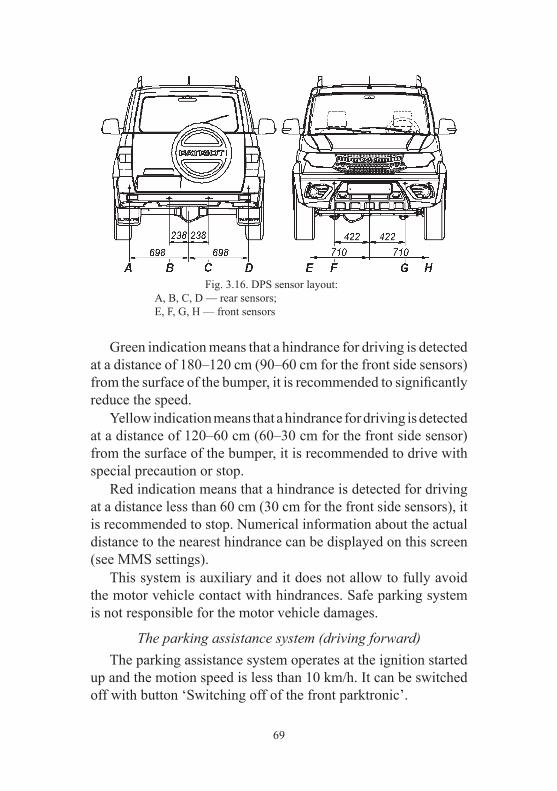
69
Fig. 3.16. DPS sensor layout:А, В, С, D — rear sensors;E, F, G, H — front sensors
Green indication means that a hindrance for driving is detected at a distance of 180–120 cm (90–60 cm for the front side sensors) from the surface of the bumper, it is recommended to significantly reduce the speed. Yellow indication means that a hindrance for driving is detected at a distance of 120–60 cm (60–30 cm for the front side sensor) from the surface of the bumper, it is recommended to drive with special precaution or stop. Red indication means that a hindrance is detected for driving at a distance less than 60 cm (30 cm for the front side sensors), it is recommended to stop. Numerical information about the actual distance to the nearest hindrance can be displayed on this screen (see MMS settings). This system is auxiliary and it does not allow to fully avoid the motor vehicle contact with hindrances. Safe parking system is not responsible for the motor vehicle damages.
The parking assistance system (driving forward) The parking assistance system operates at the ignition started up and the motion speed is less than 10 km/h. It can be switched off with button ‘Switching off of the front parktronic’.

70
White indication opposite to each sensor means that the sensor is operating and there are not any hindrances for driving at a dis-tance up to 90 cm from the surface of the bumber. Green indica-tion means that a hindrance is detected for driving at a distance 90–60 cm from the surface of the bumper it is recommended to significantly reduce the speed. Yellow indication means that a hindrance for driving is detected for driving at a distance of 60–30 cm from the surface of the bumper it is recommended to drive with special precaution or stop. Red indication means that a hindrance is detected for driving at a distance less than 30 cm, it is recommended to stop. Numerical information about actual distance to the nearest hindrance can be displayed on this screen (see MMS settings). This system is auxiliary and it does not allow to fully avoid the motor vehicle contact with hindrances. Safe parking system is not responsible for the motor vehicle damages.
CAMERA, REAR VIEW
Rear view camera is embedded into the licence plate lamp lining and is intended to assist the driver when driving in reverse, it displays the information about the situation on the road behind the motor vehicle on the screen. Rear view camera displays on the screen of multimedia system guide static (driving corridor) or dynamic (depending on the steering wheel angle of rotation) parking lines and the view behind the motor vehicle Fig. 3.17. Multimedia system draws the dynamic parking lines, receiving the signal from the steering wheel angle of rotation sensor and imposes them on the video. Dynamic parking lines are moving synchronously and in the same direction as the steering wheel. Rear view camera switches on when the gearbox lever is in ‘back run’ position. Distance line (red) Fig. 3.17. This line shows the distance behind the motor vehicle: the line is located in 0.6 m from the spare wheel plane.

71
Distance line (yellow). This line shows the distance behind the motor vehicle: the line is located in 1.2 m from the spare wheel plane. Distance line (green). This line shows the distance behind the motor vehicle: the line is located in 1.8 m from the spare wheel plane. Note: – rear view camera is an auxiliary equipment for driving in reverse and it does not negate the driver’s responsibility; – the camera has “dead zone” where the hindrances cannot be detected; – when driving in reverse with a trailer the lines on the screen show the motor vehicle motion, but not the trailer motion; – the screen displays only the area behind the motor vehicle. That is why when rotating the steering wheel during the driving in reverse monitor the situation on both sides outside the vehicle; – if the lens of the camera is dirty the quality of the picture worsens hence, the lens should be regularly cleaned from dust and dirt. Standard glass cleaning alcohol — based detergents may be used and dry lint-free wipes.
Fig. 3.17. Static and dynamic parking lines: a — red line; b — yellow line; c — green line
Static parking linesDynamic parking lines
1.8 m
1.2 m
0.6 m

72
“CRUISE CONTROL” AND “OVERSPEED LIMITER” SYSTEMS
“Cruise control” system (CC) is intended for automatic main-tenance of the programmed speed of the motor vehicle without pressing the accelerator pedal. “Overspeed limiter” system (OSL) is intended for automatic limitation of the permissible vehicle speed set by the driver. The CC and OSL systems include the following devices: – electronic engine control unit (ECU). Includes CC and OSL function algorithm to control engine torque; – instrument cluster (IC). Shows the current of CC and OSL functions; – steering system keys unit (Fig. 3.17). It is intended for CC and OSL functions control;
Steering system keys unit CC and OSL functions are controlled with the following keys (Fig. 3.18): 1 key — “Cruise control” function selection; 2 key — “Overspeed limiter” function selection; 3 key “Set +” — activation of the selected function, increase of the set speed (for CC), increase of the speed threshold (for OSL); 4 key “Set -” — activation of the selected function, decrease of the set speed (for CC), decrease of the speed threshold (for OSL);
Fig. 3.18. Steering system keys unit of CC and OSL (for names of items, see the relevant text)

73
5 key “RES” — resumption of the selected function; 6 key “CAN” — cancellation of the selected function.
Principle of operation of “Cruise control” function1. Turning on/off.
CC function is turned on by pressing key 1 (Fig. 3.18). Repeated press of key 1 will cancel CC function. Pressing key 1 when CC function is activated, will deactivate and turn off CC function. The preset speed value will be deleted from the ECU memory. Pressing key 2 (Fig. 3.18) when AC function is on, will deac-tivate CC function and will activate OSL function. Pressing key 2 when CC function is activated, will deactivate and turn off CC function and turn on OSL function. The preset speed value will be deleted from the ECU memory.
2. Activation.
For activation turn CC function on (indicator lights up white), push the accelerator pedal and reach the desired speed. Then fix the target speed by pressing key “Set +” or “Set -”, i.e., the system is activated (indicator lights up green) under the following conditions: – the motor vehicle speed should exceed or be equal to 40 km/h and should be less or equal to 150 km/h; – crankshaft rotation frequency should exceed or be equal to 850 rpm or should be less or equal to 5,000 rpm; – gearbox transmission must not be lower than third; – brake pedal should be pushed once after starting the engine. The accelerator pedal should be released after that. The motor vehicle will maintain the selected speed automatically.
3. Change of the target speed. The target speed is changed when the motor vehicle is moving with activated CC function. Single press of key “Set +” leads to stepwise change of the target speed by 1 km/h.

74
Single press of key “Set -” leads to stepwise decrease of the target speed by 1 km/h. Pressing of key “Set +” for more than 0.5 s will smoothly increase the vehicle speed. New speed value changes to the current speed value at the moment when the key is released. The acceleration regime is limited to 150 km/h. Pressing of key “Set -” for more than 0.5 s will smoothly decrease the speed. New speed value changes to the current speed value at the moment when the key is released. The deceleration regime is limited to 40 km/h. Single pressing of keys “Set +” or “Set -” in overtaking mode (item 4) will set the current speed as the target one.
4. Overtaking mode. If the accelerator pedal is pushed, CC function will switch to the overtaking mode which leads to the speed increase. After the accelerator pedal is released CC function will automatically reduce the speed to the target value. At changing of the acceleration (long pressing of “Set +”) or deceleration mode (long pressing of “Set -”) to overtaking mode the target speed will change to the current speed value at the moment the accelerator pedal is depressed.
5. Gear shift mode. Gear shift mode allows to temporarily deactivate CC func-tion during gear shift from the moment when the clutch pedal is depressed and automatically resume the function after the clutch pedal is released. The gear shift is possible for the gears not lower than third.
6. Deactivation. CC function is deactivated with saving the target speed in the memory of ECU in the following cases: – if the brake pedal is depressed; – if the clutch pedal is depressed for more than 5 s in the gear shift mode (item 5);

75
– if the accelerator pedal is continuously depressed (for more than 120 s) – in the overtaking mode (item 4); – if deactivation key “CAN” is pressed; – if gear is shifted to neutral; – the function cannot keep the preset speed (for instance, on inclines and descents). If CC function is deactivated (for instance, if the brake pedal is depressed) during acceleration phase (long pressing of “Set +” key) or deceleration (long pressing of “Set -” key), the target speed will be changed to the current value of the speed at the moment when the CC function is deactivated. If the function is deactivated by pressing keys “CAN’ or “CC”, the torque will be smoothly decreased.
7. Resumption. Resumption of CC function is possible if key “RES” is pressed. The target speed value will be taken from the system memory at the moment of the previous deactivation of the function. Resumption mode is possible only if the ECU memory keeps the target speed value different from zero. The pressing of keys “Set +” or “Set -” during active resump-tion mode will lead to setting of the current speed as the target. The resumption mode can be interrupted by pressing and holding of keys “Set +” or “Set -” with further transfer to acceleration or deceleration modes accordingly. The target speed will be changed to the value at the moment when the acceleration or deceleration mode starts.
Principle of operation of “Overspeed limiter” (OSL) function
1. Turning on/off. OSL function is turned on by pressing key 2 (Fig. 3.18). The repeated pressing of the key 2 will turn off the OSL function.

76
Pressing key 2 when OSL function is activated will lead to the deactivation of OSL function and its turning off. The value of the preset speed threshold is saved in the nonvolatile memory of the ECU. Pressing key 1 when OSL function is on, leads to turning OSL function off and AC functions on. Pressing key 1 when OSL function is activated leads to OSL function deactivation and turn off, and CC function turn on. The value of the preset speed threshold is saved in the nonvolatile memory of the ECU.
2. Activation. The fixed speed threshold of the motor vehicle is set, i.e., acti-vated, when OSL function is on (indicator lights up white), then pressing keys “Set +” or “Set -” either in the stationary vehicle or while driving (indicator lights up green). The following condition must be implemented: – the motor vehicle speed should be less or equal to 150 km/h. If the motor vehicle speed is less than 40 km/h, then the speed threshold setting value at the moment of activation is 40 km/h. If the motor vehicle speed exceeds 40 km/h or is equal to 150 km/h, then the setting speed threshold value at the moment of activation is assumed to be equal to the current speed of the motor vehicle.
3. Change of the set speed threshold of the motor vehicle.
The set speed threshold can be changed either when the vehicle is stationary or while driving with OSL function activated: Single pressing key “Set +” leads to stepwise increase of the set speed threshold by 1 km/h. Single pressing key “Set -” leads to stepwise decrease of the set speed threshold by 1 km.

77
Pressing of key “Set +” for more than 0.5 s leads to stepwise increase of the set speed threshold by 10 km/h each 0.5 s, and the highest threshold is limited to 150 km/h. Pressing of key “Set -” for more than 0.5 s leads to stepwise decrease of the set speed threshold by 10 km/h each 0.5 s and the lowest threshold is limited to 40 km/h. Single pressing of keys “Set +” or “Set -” in overtaking mode (item 4) will set the current speed as the threshold. At long or single pressings of “Set -” key, the set threshold cannot be fixed lower than the current speed of the motor vehicle.
4. Overtaking mode. If the accelerator pedal is pressed to 95% of its stroke, OSL function is deactivated and the vehicle speed increases without limit. Subsequent activation of OSL function occurs automatically at pressing the accelerator pedal less than 95% of its stroke and decreasing the motor vehicle speed below the preset speed threshold.
5. Deactivation. Function OSL is deactivated by pressing key “CAN”. The speed threshold value is saved in the nonvolatile ECU memory.
6. Resumption. Resumption of AC function is possible by pressing key “RES” under the following conditions: – the speed threshold value different from zero is saved in the control unit memory; – the current speed is lower than the saved threshold value. If the current speed is higher than the threshold, the pressing of key “RES” is ignored.

78
ELECTRONIC STABILITY PROGRAM (ESP) Electronic stability program (ESP) is intended for improving safety and driving convenience. ESP compares the actual vehicle trajectory with the trajectory set by the driver. If discrepancy between trajectory set by the driver and the actual one is detected the system interferes in the operation of the brake system and into the engine operation, in order to keep the vehicle trajectory set by the driver to maintain stability and drivability of the vehicle. WARNING! ESP is an auxiliary system. Do not rely on ESP only, drive with precautions (including adequate speed selection, in accordance with the situation on the road).
OSP operation in various modes When the ignition is turned on, the signal devices of switching off , operating and malfunction of ESP on the instrument cluster are switched on for approximately 3 s, after that ESP is activated. When the system comes into operation, the signal device of operation and malfunction of ESP on the instrument cluster starts flashing. ESP operation may be accompanied by light pulsation and automatic operation of brake mechanisms. This is not a deviaton from the norm. For improvement of traction characteristics of the motor vehicle on dirty or slippery road, the crankshaft rotation frequency at pressing the accelerator pedal (even to the extreme position) may not increase. It is needed to maintain the vehicle, to hold adhesion of the wheels to the road, and is not a sign of a malfunction. ATTENTION! It is not recommended to install tires the size of which differs from those installed at the manufacturing plant. At changing tires, the size of which differs from the installed ones, to ensure correct ESP and speedometer operation, it is necessary to save the new tire size in the ESP electronic control unit memory. For this, contact UAZ LLC service station (the addresses of service stations are listed in the service book).
79
To deactivate ESP, press the ESP deactivation switch for approx. 2–3 s with the engine on, the signal device of ESP turn-off will light up on the instrument cluster and the dynamic stability system and traction control system will turn off. LED-display of the cluster shows the following message: “Electronic differential lock is off”, the message is accompanied by the horn. To turn ESP on, press the ESP turn-off switch once again, signal device of ESP turn-off will go out, automatic system activation will occur, if the speed exceeds 75 km/h and when the ignition is turned off. ATTENTION! In case of ESP system malfunction the instru-ment cluster signal device of operation and malfunction of ESP is on continuously. In this case, contact UAZ LLC service station (the addresses of service stations are listed in the service book) to eliminate the malfunction.
Traction control system (TCS) TCS controls the engine torque and the brake system — brak-ing torque (electronic wheel differential lock) and ensures driving without slippage of driving wheels. If one of the driving wheels is slipping on the slippery road, the TCS starts regulating the engine torque, or slows down this wheel to eliminate its slipping — in order to maintain stability and controllability of the motor vehicle. When TCS is activated, the signal device of ESP operation and malfunction on the cluster flashes. ATTENTION! To improve the traction characteristics of the motor vehicle when TCS is on, the ESP may limit the engine torque at pressing the accelerator pedal.

80
Hydraulic brake assistant (HBA) HBA is activated automatically at emergency braking, when the driver presses the brake pedal quickly, but not hard enough. HBA instantly increases the pressure in the brake system, not waiting for the driver to press the pedal in full. This allows the vehicle to start braking with maximum intensity.
Hill hold control (HHC) HHC prevents the vehicle from rolling back on a slope, hold-ing pressure in the brake mechanisms within 2 s after the brake pedal is depressed. The pressure in the brake mechanisms drops at pressing the accelerator pedal or after 2 s. ATTENTION! HHC operates in all driving modes up the inclined surface, with the exception of driving with the rear differ-ential locked (if the option of rear axle differential lock is available in the vehicle configuration) and ESP system malfunction.
OffRoad Function When the ignition is turned on, the off-road signal device lights up in the cluster for approx. 3 s, then it goes off. OffRoad increases the braking efficiency on soft surfaces (gravel, sand, deep snow, mud). Optimizes traction of wheels when driving is started and the vehicle is accelerating on soft surfaces (gravel, sand, deep snow, mud). ABS shifts to “ABS OffRoad” mode. In OffRoad mode brief locking of the wheels is possible for “shovel-ing” in front of the wheels, on soft surfaces, gravel, sand, snow, mud, etc., which will facilitate the vehicle’s stopping. The function is activated when the engine is on by pressing the off-road mode switch for approx. 3 s, the off-road signal device lights up on the cluster, LED-display of the cluster shows the following message for 2–3 s: “OffRoad mode”, the message is accompanied by the sound signal.

81
The OffRoad function is deactivated by repeated pressing the off-road mode deactivation switch, for approx. 1 s or automatically when the speed exceeds 60 km/h. OffRoad function is available in all the driving modes except when the rear differential is locked (if there is the option of the rear axle differential lock in the vehicle configuration) WARNING. While driving with ESP (TCS) activated (for instance, during long ascent with slippery surface or during slip-ping in mud, snow, sand, etc.) the brakes may overheat, which may affect the efficiency of the brake system. In this case, apply more force to the brake pedal at braking until the brakes cool down. The time needed for brakes to cool down depends on the environment (ambient temperature, motor vehicle speed, etc.).
ESP availability in various modes
Mode ESP, TCS, ABS condition Signal device
2H ESP, TCS, ABS are available –2H+OffRoad ESP is available
TCS is availableABS is available in operation mode “ABS OffRoad” up to 40 km/h, above 40 km/h, ABS operates in its usual mode
)*
4H ESP, TCS, ABS are available –4H+OffRoad ESP not available
“Electronic wheel differential lock” is available“ABS OffRoad” up to 40 km/h, above 40 km/h, ABS operates in its usual mode
)*

82
4L ESP not available“Electronic wheel differential lock” is availableABS available
)**
4L+OffRoad ESP not available“Electronic wheel differential lock” is available“ABS OffRoad” up to 40 km/h, above 40 km/h, ABS operates in its usual mode
)*
4L+rear axle differential lock (if such option is available in the motor vehicle configuration)
ESP, TCS, ABS, HHC, HBA not available
)***
)* — when OffRoad function is on, the LED-display of the cluster shows the following messages: “OffRoad mode” and “Electronic wheel differential lock is available”. )** — when mode 4L is activated, the LED-display of the cluster shows the following message: “Electronic wheel differ-ential lock is available”. )*** — when the rear axle differential lock is activated (if such option is available in the motor vehicle configuration), LED-display of the cluster shows the following message “Electronic wheel differential lock is deactivated”, “HHC is deactivated”, “ABS is deactivated”. Each message is displayed for approx. 3 s.

83
ESP availability in various driving modes when ESP is deactivated
Mode ESP, TCS, ABS condition Signal device
2H+ESP Off ESP, TCS not availableABS available
)*2H+OffRoad+ESP Off
ESP, TCS not availableABS available in driving mode “ABS OffRoad” up to 40 km/h, above 40 km/h, ABS operates in its usual mode
)*
4H+ESP Off ESP, TCS not availableABS available
)*4H+OffRoad+ESP Off
ESP, TCS not availableABS available in driving mode “ABS OffRoad” up to 40 km/h, above 40 km/h, ABS operates in its usual mode
)*
4H+ESP Off ESP, TCS not availableABS available
)*4H+OffRoad+ESP Off
ESP, TCS not availableABS available in driving mode “ABS OffRoad” up to 40 km/h, above above 40 km/h, ABS operates in its usual mode
)*
)* — when ESP is deactivated, the LED-display of the cluster shows the message: “Electronic wheel differential lock is off”. In 4L+ rear axle differential lock mode (if such option is available in the motor vehicle configuration) ESP is automatically turned off in full, the system can be turned on again with ESP availability in accordance with 4L mode, only when the speed exceeds 30 km/h or the ignition is turned off.

84
Fig. 3.19. Multimedia system steering keys unit (for names of items, see the relevant text)
To avoid engine torque decrease, to roll the vehicle when stuck in snow or mud turn ESP off. WARNING. If the vehicle is stuck in snow, mud, sand, etc., try to release the vehicle by rolling it forward-backward. Do not proceed like this if any people or subjects are near the vehicle. During rolling, the vehicle may be released and suddenly move forward or backward, which can lead to injuries or property damage.
MULTIMEDIA SYSTEM KEYS UNIT
Function of multimedia system keys (Fig. 3.19). 1 — input key in the “Phone” mode . Short pressing: answering the incoming phone call or dialing the phone number from the calls list. Long pressing: shows the list of the calls. 2 — input key in the “Phone” mode . Short pressing: phone call finishing or declining or closing the calls list or turning the sound on/off; 3 — key “SRC»”/“SRC«” (up/down) sound source selection. If radio is activated: press to select the next/previous preset radio station tuning.

85
If SD-card is activated: press to select the next/previous audio file. If the phone portal is activated: press up/down, to select the next/previous record from the list of phone calls. If the phone portal is on and some calls are on hold: press up/down to switch between the calls. 4 — volume up key “+”. 5 — volume down key “-”.
VEHICLE INTERIOR AND BODY EQUIPMENT
Interior heating, ventilation and conditioning Interior ventilation and heating are adjusted depending on the ambient temperature by mixing of cold and heated air and are maintained at almost constant level, at any speed of the vehicle. Fig. 3.20 shows the interior ventilation and heating system control unit. 1 — control unit side deflector. 2 — windshield blower (heating) nozzle. 3 — control unit central deflector. 4 — heating and ventilation control unit. 5 — floor tunnel deflectors. 6 — air-flow control lever. 7 — flap control lever. Climate-control system has the control panel, which is the mail control device. To control the interior temperature according to the temperature set by the driver, the control device receives the incoming signals from several sensors, such as the interior tem-perature sensor, ambient temperature sensor, coolant temperature sensor, solar radiation sensor, as well as from the control panel switches.

86
The unit controls the flap actuators, such as air current distribu-tion flap actuator, air mixture flap actuator and air intake actuator. The unit controls cooling/heating, the information on the system operation is displayed on the screen. Besides this, the unit maintains comfortable air conditioning in the interior by automatic control of air cooling speed and air volume. The display shows the set value of the interior temperature. The control unit detects faults and informs the driver about them, and besides this, it can shift to trouble-free operation.
Fig. 3.20. Interior ventilation and heating systems control elements (for names of items see the relevant text)

87
Control panel (Fig. 3.21) 1 — rotary switch of the air supplied temperature. Rotate to the right — warmer, to the left — cooler. Control range: LO, 19 °С ~ 25 °С, Hi with 1 °С pitch. LO — Maximum cooling control mode; HI — Maximum heating control mode; 2 — rotary switch of air current distribution (Fig. 3.21 a, b). The switch has five fixed positions. Each position corresponds to a specific distribution of air currents in the motor vehicle interior: — interior and feet air cooling via deflectors, if flaps are open; — interior air cooling via deflectors, if flaps are open; — windshield air cooling; — windshield and feet air cooling; — feet air cooling; Direction of the air current can be changed via small levers 6 (Fig. 3.20) on the deflectors. 3 — rotary switch of air fan control. Position 0 (air fan is off). Position “Auto” (Fig. 3.21c): to reach the target temperature the system will be controlled automatically. Other positions: steps 1~ 8. 4 — push button switch of mode “Supply air — recirculation” (Fig. 3.21) with light indicator. The button in the air fan control handle may switch the air supply mode to the recirculation mode. 5 — push button switch of the windshield intensive heating. It shifts the air flow to the windshield. The button in the mode handle may direct the air fan to the windshield. 6 — rotary switch marker. 7 — button switch of air conditioning mode (Fig. 3.21 b, c) with light indicator. The air conditioner button in the temperature control handle may switch on or off the air conditioner compressor.

88
Fig. 3.21. Heater control panel:a — ventilation and heating control unit;b — interior ventilation and heating with air-conditioning control block;c — Climate system control unit (climate-control).(for position names, see the relevant text)
a
b
c

89
8 — button switch of the interior air cooling. 9 — button switch of feet air cooling. 10 — button switch of the windshield air cooling. 11 — button switch of intensive windshield heating. Directs the air flow to the windshield. 12 — display. On motor vehicles with additional interior heater, heating rate of the rear triple passenger seat can be increased. In order to do this, turn on the electric motor fan, additional heater valve with electric drive 11 (Fig. 3.22) using the switch 7 (Fig. 3.11) positioned at the rear panel of the floor container. Direction of air currents is adjusted by two deflectors. On the motor vehicles not equipped with an additional heater, additional heating of the rear seat passengers is conducted through the feet air cooling air duct passing through floor tunnel.
Fig. 3.22. Additional heater:1 — heater tubes; 2 — hose for supplying the cooling fluid to the heater; 3 — fitting; 4 — lid of the compartment in the floor tunnel lining; 5 — switch unit (Fig. 3.11); 6 — case of the tunnel lining glove compartment; 7 — deflector (control elements on Fig. 3.20); 8 — deflector sealing; 9 — support; 10 — enclosed radiator and electric fan of the additional heater; 13 — valve with electric drive
turned

90
Heating and ventilation system is equipped with an air-intake filter. The filter should be changed after 30,000 km mileage or once per year, depending on what comes first. Access to the filtering element is provided below the dashboard, at the feet of the front passenger. Changing of filtering element 5 (Fig. 3.23) should be performed as follows: – force latches 3 away from cover and remove cover 4; – replace filtering element 5; – lock filter cover 4. ATTENTION! Using the operation modes of the heater fan from above average to maximum output rate in pouring rain con-ditions can result in soaking of the air-intake filter and ingression of moisture at the feet of the front passenger.
Interior ventilation Blowing ventilation of the interior is performed via the same channels, when the handle 1 (Fig. 3.21) is arranged at maximum counter clockwise position. Drawing ventilation is performed via air
Fig. 3.23. Air fan:1 — dashboard; 2 — fan; 3 — fan cover; 4 — cover latches; 5 — filtering element

91
holes in the rear roof liner and inner panel of the tail gate apertures, via ventilation grille with valves and rolled down door window.
Automatic temperature control When the automatic temperature mode is on, the panel controller calculates the required control mode, basing on the sensors signals and internal programs, and controls the air conditioner compres-sor after the required temperature is set by the electric air fan and flaps actuators, to provide comfortable feeling in the interior.
Air fan actuator control When AUTO mode is ON, the control panel controls the air fan speed, in order to obtain the required temperature. Manual control of air current direction and switching the air conditioner and recirculation on/off is also available.
Control panel operation mode (Fig. 3.21) “Manual” operation mode is the main mode of the control panel. While rotating the air fan handle 3 (Fig. 3.21) within points 1 and 8 the system switches to manual control, and the air fan speed increases by 1 point up and down, within the points range. When this mode is switched on, the control panel scans the condition of the control elements (rotary switches 1, 2 and 3) and, depending on their positions, works in accordance with the prescribed operation algorithm, determines the condition of the recirculation flap 4, A/C switch 7, position of the rotary switches. “Intensive windshield heating” switches on by switch 5 (Fig. 3.21 a, b) or 11 (Fig 3.21 c), transmitting a signal to the control panel, which generates and transmits to executing devices the control signals needed for the control panel to switch to the required mode. In this mode, the control panel changes the position of the air distribution flap to “To the window” position, air damper to posi-tion, which corresponds to the 8th switch position 1 (Fig. 3.21). However, rotation speed of the climate control unit fan corresponds with 8th positions of switch 3. In this mode, the control panel does not react to changes in positions of the rotary switches.

92
If the control panel in “Intensive windshield heating” mode receives a signal to switch on a conditioner, then the conditioner will be switched on and the system will perform the drying of the climate control unit. “AUTO” mode turns on by switch 3 (Fig. 3.21 c) in position “ ”. In this mode the unit controls the air damper, so that the tem-perature set by rotary switch 1 (Fig. 3.21 c) is maintained auto-matically. It is possible to manually set the required air current distribution (by mode buttons 8, 9, 10). “AUTO” mode turns off after switch 3 is shifted from position “ ” to any other position, or after “Intensive windshield heating” mode is ON. In cold weather (AUTO mode, ambient temperature is: lower than 15 °С), the system first automatically selects constant low speed and the flap position of the windshield air cooling, until the heater starts supplying warm air to avoid discomfort caused by cold air. In hot weather (AUTO mode, ambient temperature is: higher than 30 °С), the system first automatically selects constant low speed and the flap position of the windshield air cooling within 5 s, and then it returns to the normal control to avoid discomfort caused by hot air. “Interior preheating”+ mode. The control panel goes to “Interior preheating” mode if the source of power is the liquid heater. When this mode is turned on (the ignition is turned off), the control board indicates this mode with orange blinking illumina-tion on rotary switch 2 with a 4.5 s blinking period (1.5 s turned on/3 s turned off). If the position of rotary switch 3 exceeds position 4 of the switch, then the control panel limits the maximum rotation speed of the fan and rotary switch 3 goes to the 4th position in order to prevent forced accumulator battery discharge.
93
If rotary switch 3 is turned to ‘OFF’ position, then the rotary speed of the fan corresponds to position 2 of rotary switch 3 (i.e. fan is rotating at minimum speed). When the “Preheating interior” mode is turning on, the heater flaps go to the following positions: – air current distribution flaps to “At the feet” position; – recirculation flap to “Opened” position (air induction from the motor vehicle interior); – choke flap to “Maximum opened” position (maximum air temperature). After 5 minutes in the above described positions, the control panel changes the positions of the flaps to “Ventilation of the interior and at the feet” position. The control panel remains in the current operation mode with current flap positions until the liquid pre-start heater is turned off or ignition is turned on. If the ignition is turned on before the liquid pre-start heater is turned off, then the control panel automatically goes to “Manual” operation mode and the actuating elements of the climate control unit are adjusted in accordance with the control elements of the climate control unit.
Air conditioner Depending on the configuration, the motor vehicle can be equipped with air conditioner. To switch the air conditioner on push button 7 (Fig. 3.21 b, c). The control panel switches on the air conditioner if the air temperature at the evaporator output is above or equal to 7 °C. If the air conditioner is operating and the air temperature decreases to 4 °C or lower, then it turns off regardless of the A/C switch position. When the control panel receives the signal from the A/C switch to turn off the air conditioner, the control panel turns it off. Recirculation mode can be activated with a button for more effective cooling (air induction from the motor vehicle interior).

94
WARNING. Prolonged usage of the recirculation mode can cause window fogging and stuffy air in the interior. ATTENTION! Turn on the air conditioner even during cold seasons at least one to two times per month for 5–10 minutes. It provides the required compressor lubrication and extends the service life of the system. ATTENTION! In order to prevent the engine from overheat-ing, when the air conditioner continuously works at idle engine run and when moving in severe conditions with the engine load near to full, the air conditioner compressor can often be shut off together with a loss of cooling efficiency. In order to improve the air conditioner efficiency in the given conditions, it is recommended that the rotation speed of the climate control unit fan be raised at the flick of switch 3 (Fig. 3.21) and a minimum air temperature be set at the flick of switch 1, additionally turn on the “recirculation of air” for a short time — 5–10 minutes. One of the features of the system (for motor vehicle with air conditioner) is the glove compartment cooling function. For cool-ing the glove compartment switch the rotary tumbler 4 (Fig. 3.24) in “Open” position.
Fig. 3.24. Glove compartment:1 — glove compartment lamp; 2 — cool air supply pipe; 3 — glove compartment lamp switch off sensor; 4 — glove compartment cooling switch on tumbler
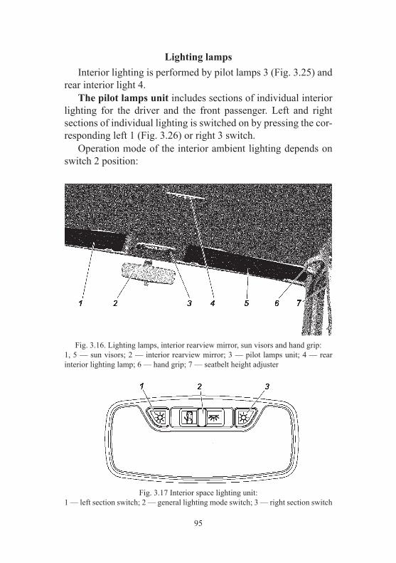
95
Lighting lamps Interior lighting is performed by pilot lamps 3 (Fig. 3.25) and rear interior light 4. The pilot lamps unit includes sections of individual interior lighting for the driver and the front passenger. Left and right sections of individual lighting is switched on by pressing the cor-responding left 1 (Fig. 3.26) or right 3 switch. Operation mode of the interior ambient lighting depends on switch 2 position:
Fig. 3.16. Lighting lamps, interior rearview mirror, sun visors and hand grip:1, 5 — sun visors; 2 — interior rearview mirror; 3 — pilot lamps unit; 4 — rear interior lighting lamp; 6 — hand grip; 7 — seatbelt height adjuster
Fig. 3.17 Interior space lighting unit:1 — left section switch; 2 — general lighting mode switch; 3 — right section switch

96
— the lamp switches on and off automatically, when opening or closing the door. The interior lamp is on if any of the motor vehicle doors are open. After closing all the doors, the lamp lights for 25 s (depending on the configuration), and then smoothly goes off for 2 s. — the lamp is on until it is switched off. When switch 2 is in mid-position, the lamp switches off. Lamp of the luggage compartment turns on (Fig. 9.45) when opening the tail gate. The control of the interior lighting units (“gentle” light) with a smooth change of brightness for 2 s when turning on and off the interior lighting lamps is enabled: – when opening any of the side doors; – when turning on and off the “Security” mode via a radio channel of the remote control panel; – when receiving “Find motor vehicle in unlighted parking area” command via remote control panel; – when turning on the ignition, after all the doors are closed while the lamp is still in ‘ON’ position; – 25 s after all the side doors are closed, if during this period the ignition was not turned on, any of the side doors were not open, the “Security” mode was not switched on via a radio channel of the remote control panel; – in 10 minutes when one or more side doors are constantly open (if during this period all the side doors were not closed, the tail gate was not opened or closed, the ignition was not turned on). The lighting turns on when the ignition is turned off and the doors are open, and also for not more than 25 s after all the doors are closed. When the ignition is turned on, the interior lighting is on only if at least one side door is open.
Interior rearview mirror (Fig. 3.25) Interior mirror is adjusted by pivoting around its joint. ATTENTION! In order to avoid blinding by headlights of vehicles traveling behind during night driving conditions, it is necessary to change the tilt angle of the mirror with a lever posi-tioned below the mirror.

97
Fig. 3.27. Exterior mirror folding scheme (for UAZ PATRIOT, UAZ PICKUP)
Exterior rearview mirrors The exterior mirror optimal position for UAZ PATRIOT, UAZ PICKUP is selected by switch 9 (see Fig. 3.14, for UAZ CARGO — manual adjustment. The rearview mirrors are heated using switch or located on the instrument cluster. In order to reduce the motor vehicle size when parking in tight space, it is necessary to fold in the exterior rearview mirrors to the side doors of the motor vehicle (for UAZ PATRIOT, UAZ PICKUP). The mirror folds by applying force to the most remote from the base cover or body edge, parallel to the coupling line of the body and the cover (Fig. 3.27).
Sun visors (Fig. 3.25) In case of necessity it is recommended that the sun visors be positioned in either of the two positions: flip the sun visor into its downward position or flip it down and turn toward the side door.
Coupling line of the body and the cover
Most remote from the base cover edge
Most remote from the base body edge

98
Fig. 3.29. Tail gate (view from outside):1+ — rear view camera; 2 — door handle; 3 — number plate lighting lamps lining case
Doors ATTENTION! Before opening a door, make sure it will not be a hindrance for other road users. Before closing a door, make sure it will not catch someone or something. Driver’s door is locked with a key from outside. If it is not locked, the door opens when pulling moving part 2 (Fig. 3.28, 3.19) of the door handle.
Fig. 3.28. Front door (view from outside):
1 — door lock switch; 2 — movable part of the door handle; 3 — door handle body

99
The door opens from inside when turning handle 2 (Fig. 3.30, 3.31) toward you. Lock/unlock the doors by pushing/lifting the button 1 (Fig. 3.30, 3.31).
Fig. 3.30. Front door (view from the interior):
1 — locking button; 2 — door handle; 3 — armrest handle; 4 — pocket; 5 — place for loud-speaker mounting; 6 — switch unit (Fig. 3.9, 3.23); 7+ — place for twitter mounting
Fig. 3.31. Rear door (view from the interior):
1 — locking button; 2 — door handle 3 — power window control switch; 4 — place for loud-speaker mounting; 5 — pocket; 6 — lever for locking door interior handle; 7 — armrest handle
100
The tailgate is not equipped with an inside handle, which opens it or a button which blocks the lock. The motor vehicle is equipped with an electric blocking system of the door locks. When locking the front left door with a key, all the door locks are locked simultaneously. Every door (except the front left door) can be locked or unlocked individually from inside the interior by pressing the corresponding door locking button. ATTENTION! When leaving the motor vehicle, do not leave the door key or ignition key inside it. Passengers inside the motor vehicle, especially children, could accidentally lock all the doors. The locks in the rear doors and the tail gate have interior handle blocking levers (“child lock”) which prevent the doors from open-ing from inside the motor vehicle. The handle is locked by turning lever 6 downward (Fig. 3.31). Rear doors can be locked when a door is opened. The front doors can be locked only when a door is shut (to pre-vent accidental leaving key inside the cabin). The windows of the side doors go up and down by turning the switches of the power windows 3,4,5,6 (Fig. 3.14). ATTENTION! When closing the power windows, fingers or other body parts may be caught, which could lead to serious injury. Therefore, pay attention when using the power windows, especially if there are children in the motor vehicle. If there is a child in the motor vehicle, make sure there are no body parts of the child in the window aperture when opening/closing the window. If a body part it caught, it is necessary to stop closing the window immediately and start to open it. When there are children in the motor vehicle, it is recommended that the power windows be turned off using switch 1 (Fig. 3.14). The driver bears full responsibility for inappropriate usage of the power windows. The driver should inform the passengers about the directions of use and dangers when the power windows are used inappropriately.
101
Keep children away from the switches of the power windows! Do not hang hands or other body parts out of the open window, keep children from doing this. When leaving the motor vehicle, it is necessary to take out the ignition key in order to turn off the power windows and prevent the passengers left in the motor vehicle from getting injured accidentally. If the key was left inside the motor vehicle, the system warns the driver about it by making the immobilizer buzzer produce beeping sounds when the driver’s door is open. Never close the motor vehicle from outside if there are passen-gers inside it — it will not be possible to open the windows from inside the motor vehicle. When closing/opening the windows, keep in mind the safety requirements. Successful performance of the power windows depends on the cleanliness of the windows.
Seats ATTENTION! Do not adjust the driver’s seat when the motor vehicle is moving. The driver’s seat and tilt angle of the steering column should be adjusted so as to provide the necessary position of the driver: the driver should tightly bear against the back rest of the seat; elbow joints of both arms should be slightly bent when holding the upper part of the steering wheel; the legs should not be extended at full length when pressing the pedal as far as it can go. The seat headrests should be adjusted so that the back of the head touches the midpoint of the headrest when the head rests upon it. If it is not possible, then the headrest should be raised to the uppermost position for very tall persons and lowered to the lowermost position for very small persons. After adjusting the positions of the front seats, it is necessary to adjust the position of the upper mounting points of the seatbelts. It is forbidden to sit on the knees and load the individual points of the seat in different ways so as not to damage the heat-ing elements.

102
Do not use the heating mode if the seats are not occupied by passengers or there are any items such as a special baby seat, bag, etc. This may cause a malfunction of the heating elements of the seat heating system. It is recommended that the switches of the heating system be turned on only when the engine is started. It significantly saves the accumulator battery capacity. If the voltage drops in the electrical on-board system of the motor vehicle, the seat heating is automatically switched off to provide sufficient power for the engine control system. If you or a passenger suffer from low pain or temperature threshold, e.g. as a result of drug treatment, paralysis or chronic disease, it is recommended that you do not use the heater. It may result in burns on the back, buttocks and legs. If you still want to use the seat heating, it is recommend that you turn on the heating for short periods of time. Do not use additional pillows between the seat and the pas-senger or the driver. It is forbidden to place foreign objects under the driver’s seat and in the area of his feet. Changing of the headrest height or its removal is performed by moving the headrest in a vertical direction: – up — by arm force (to the uppermost position); – down — when the button of the headrest lock is switched on. Removal is performed by moving the headrest upward from the uppermost position while pressing the button of the headrest lock. Adjustment of the front seats in the longitudinal direction is performed by lever 1 (Fig. 3.32): pull the lever located under the seat cushion which blocks the longitudinal movement of the seat and move the seat to the desired position. When the adjustment is finished, release the lever and make sure that the seat is securely fixed by moving it back and forth when the lever is released. Backrest angle is controlled (stepless adjustment) by turning handle 3 at the base of the backrest.

103
For your convenience, make the adjustments with the door open. The driver’s seat in some motor vehicle configurations is equipped with a lumbar support mechanism and seat height adjustment. Lever 4 for adjustment of the lumbar support is located on the inner side surface of the backrest. Turning the lever forward or backward results in a corresponding change of the convex sec-tion in the lower part of the seat backrest, providing comfortable support for the lumbar part of the spine. In order to raise the driver’s seat, pull up handle 2 several times until it is set to the desired height. To lower the driver’s seat, pull down handle 2 several times until it is set to the desired height. For your convenience, make the adjustments with the door open. Rear triple seat (Fig. 3.33) consists of pillows and backrests for one and two passengers.
Fig. 3.32. Front seat:1 — catch for locking lateral movement of the seat; 2+ — handle for adjusting the height of the driver seat airbag; 3 — handle for adjusting the tilt of the seat backrest; 4 — handle for adjusting lumber support of driver seat airbag; 5 — headrest lock button

104
In order to increase the space of the luggage compartment, the rear seat can be folded down and every part of the seat can be unfolded separately. Unfolding of the rear seat is performed as follows: – pull the loop 1 (Fig. 3.33) and set the pillow to the upright position; – remove headrest 2; – pull lever 3 in the direction of movement of the motor vehicle, release and fold the backrest as shown in the diagram, Fig. 3.33; – to return the backrest to its initial position, raise the backrest until the headrest lock is activated; – to return the pillow to its initial position, turn it back to the horizontal position (only for UAZ PATRIOT); – the pillow should be fixed in the following sequence: lift the seatbelt locks and lower the pillow up to the stop (without flap-ping), pull the pillow strap retainer, press the pillow, release the pillow strap retainer, check the fixation (only for UAZ PICKUP); – mount the headrests. Change the position of the rear seat with the rear doors open.
Fig. 3.33. Rear triple seat:1 — releasing and raising loop of the rear seat cushion; 2 — seat squab headrest 3 — rear seat squab release lever

105
Seatbelts REMEMBER! Seatbelts are efficient means of protection of the driver and the passengers against the drastic consequences of road traffic accidents. The use of seatbelts is required! ATTENTION! The seatbelts must be replaced if they have been worn or damaged and after a critical load as a result of a traffic accident. Replacement of the seatbelts must be performed only in the authorized service shops of UAZ PJSC (addresses of the authorized service shops are listed in the service book). Seatbelts are designed for individual use by drivers and adults taller than 144 cm and weighing at least 36 kg. All motor vehicle seats are equipped with three-point seatbelts (Fig. 3.34) with retraction mechanisms. To fasten the seatbelt, pull belt tongue 3 without twisting the straps and insert it into lock 4 until it clicks. Press the red button of the lock to unfasten the belt. The center seatbelt of the UAZ Pickup is a static lap belt. The seatbelt height adjuster has four fixed positions. The position of the upper mounting point of the seatbelt is adjusted by moving the belt adjuster support 1 (Fig. 3.35.) up or down. To do this, pull on the adjuster button 2 up or down. To increase the height, it is enough to pull up the adjuster support button. Depending on the motor vehicle configuration, the front seat seatbelts may additionally have a pretensioner designed for selecting possible seatbelt strap slack, and also load limiting device reducing the holding force on a person to provide more efficient protection in case of road accident. The pretensioner device actuates regard-less of whether or not a person is fastened with a seatbelt.

106
Fig. 3.35. Height adjuster:1 — belt guide support group; 2 — adjuster button
Fig. 3.34. Seatbelts:1 — seatbelt height adjuster; 2 — seatbelt guide bracket; 3 — lock catch; 4 — lock; 5 — inertia reel; 6 — clip; 7 — adjuster for static middle belt (UAZ Pickup)
Strap extension Strap shortening
pull pull

107
Keep the seatbelt straps and buckles clean. If they become dirty, clean them with an alkali-free soap solution. Protect the straps from touching sharp edges. Protection from direct sunlight is recommended. In order to clean the straps from dust, blow with compressed air not less than once per year. It is forbidden to: – twist the straps, fold them lengthwise and allow excessive slack; – iron the straps; – strap in a child sitting on the lap of a passenger; – make changes in the belt design. ATTENTION! When the motor vehicle moves, the seat back-rest angle should be minimal, but sufficient for the convenience of the driver and passengers. The seatbelts are more effective when the driver and passengers sit up straight, resting on the backrest. If the seat backrest is inclined too much, the seatbelt may slip, increasing the risk of getting injured in an accident. ATTENTION! Control the condition of plastic restriction clip 6 (Fig. 3.34) of the center seatbelt.
Unfastened seatbelt signal device. If the seatbelt of the driver is not fastened when the ignition is turned on, the seatbelt signal device on the instrument cluster turns on. The signal device turns off when the ignition is turned off or the strap is inserted to the retractable seatbelt. If the motor vehicle moves for more than 60 s or 500 meters or reaches speed of 25 km/h and the seatbelt of the driver is not fastened, an additional horn turns on. When the motor vehicle moves and the seatbelt of the driver is not fastened within 30 s, the warning horn turns off. After the motor vehicle stops and then starts again, the audio alarm algorithm will repeat, if the driver’s seatbelt is not fastened.

108
Diagnostics of defective unfastened seatbelt indicator
Seatbelt signal device is on when the driver’s seatbelt is fastened. Disconnect the receptacle of the retractable seatbelt buckle: – the signal device goes of, if the retractable seatbelt buckle is defective; – the signal device remains illuminated, if the wiring harness or the instrument cluster is defective.
Airbags Motor vehicle is equipped with front airbags system for the driver and the front passenger, front seatbelts with pretensioners and the load limiter. When the airbags system actuates, the front seatbelts are retracted within a short period of time for secure fixa-tion of the driver and the passenger and the air bags are filled with gas, and unfolding in front of the driver and the front passenger, reduce the danger of head and upper body part injuring. Airbags system actuates at frontal collision of motor vehicle, when it is needed to increase the safety of the driver and the front passen-ger. The presence of airbags system is marked by the inscription “AIRBAG” on the steering wheel cover, inscription “AIRBAG” on the dashboard cover and inscription “AIRBAG” on the seatbelt strap label. Airbags system includes: – driver airbag module built into the steering wheel; – airbag module located in the dashboard above the glove compartment; – front seatbelts with load limiter; – driver seatbelt condition sensor; – front seatbelts locks with pretensioner; – rotating device mounted on the understeering switch con-nector (for connecting of the horn switch-off and airbag module to the vehicle circuit board);

109
– airbags control unit mounted between the driver and the pas-senger seats; – signal device of airbags system control malfunction on the instrument cluster; – signal device of unfastened seatbelt on the instrument cluster. Airbags are auxiliary means of protection for the fastened driver, front passenger, and they actuate at severe frontal collision, starting from a specific collision severity; Airbags system should actuate at severe frontal collisions. However, the airbags system may actuate in other emergency situations, if the vehicle experiences an impact similar to that at severe frontal collision. Situations when the airbags system actuates: – collision with non-deformable fixed barrier: airbag actuates at slow vehicle speed; – collision with moving deformable barrier (for instance, with another motor vehicle): airbag actuates only at high vehicle speed; – in case of a sufficient force of front impact on the vehicle, some examples are shown on (Fig. 3.36). Airbags system does not actuate if: – the ignition is off; – minor frontal collisions; – vehicle rollover; – side or back blows to the vehicle, i.e., in cases when the airbag is not able to increase the driver’s safety. Damage degree of the vehicle body at collision (or absence of serious damage) is not always an indicator of frontal airbags malfunction or normal function. When airbags unfold, there is almost no danger of limiting visibility for the driver, as the airbag is filled and emptied for a short period of time. The airbag provides optimum protection if the seat, backrest and headrest are mounted correctly. The whole back should be tightly born against the back-rest of the seat, and the seat should be as far as possible for the driver in a vertical seated position to hold the steering wheel with

110
elbow joints of both arms slightly bent. The front passenger seat should be pushed back as far as possible and the backrest should be brought back to a vertical position to avoid any discomfort. Incorrect seating, in case of the airbag unfolding, may result in serious injury or death. The airbag needs space for being filled with gas. Airbag system is an autonomous one-off device and it does not require any maintenance during operation of the motor vehicle. After airbag system actuation, the control unit and airbag modules, as well as seatbelts with pretensioner should be replaced by an authorized dealer. ATTENTION! Because of the impossibility of the front pas-senger airbag unfolding, do not install child seat against the direction of movement (backrest forward) on the front passenger seat. If the airbag actuates, a child can be seriously injured. In motor vehicles equipped with the front passenger airbag, there is a warning label on both sides of the sun visor (Fig. 3.37) prohibiting the installation of child seat with backrest forward.
Fig. 3.36. Examples of situations when the driver and front passenger passive safety system actuates
Bumping into curb, pavement edge or solid material
Falling or trembling at deep holes
Hard ground contact or car falling from brow

111
WARNING! 1. An airbag does not replace seatbelt, it only complements its action, therefore always fasten the seatbelt. Those who do not fasten seatbelts run the risk of being more seriously injured during an accident, or even be thrown out of the vehicle, and the possibility of being killed is not excluded. The seatbelt ensures that you have more secure seating position in case of an accident, while the airbag will provide the highest efficiency of protection. 2. Never fix foreign objects on the steering wheel and dashboard, because when the airbag unfolds, those objects can lead to injury. The same danger exists if the driver or a passenger is smoking or talking on the phone while driving. 3. Driving the vehicle, do not place forearms/palms of hands on the spot where the airbag is located. 4. While moving, the front passenger should not lean on the dashboard or handle any objects that can cause injury when an airbag actuates. 5. Airbag system malfunction signal device should turn on for 6 s after the ignition is on, and then turn off. When the ignition is turned off, and then on, before the expiration of 15 s, the signal device will not turn on. Subsequent signal device turning on, when the vehicle is in operation, means there is an airbag malfunction, and its actuation in, case of frontal collision may not be guaranteed.
Fig. 3.37. Warning label

112
6. Unauthorized interference with the airbag system is forbid-den. All works should be carried out only at authorized dealers by specially trained staff. 7. Immediately after airbags actuate, some elements of the system may have high temperature. To avoid burns, do not touch hot parts. 8. Skin surfaces where skin irritation signs show up should be thoroughly rinsed with soapy water. 9. If eye irritation occurs, rinse them with clear water. During prolonged irritations, consult your doctor. At motor vehicle recy-cling, it is necessary to dismantle the airbag system units at the authorized dealership.
Child restraint system installation ATTENTION! Mounting of the “universal” child restraint system, in accordance with Table 3.2, is performed with the seatbelts of the vehicle. Children under 1.5 years of age should sit in the child restraint device only facing backwards. ATTENTION! Installation of the ISOFIX child restraint system should be carried out in accordance with table 3.1 — “Mounting points for the ISOFIX child restraint system in the motor vehicle”.

113
IUF
— p
lace
sui
tabl
e fo
r set
ting
a fr
ont f
acin
g ch
ild s
eat w
hich
is “
univ
ersa
l” fo
r the
giv
en c
ateg
ory
of c
hild
se
ats w
ith IS
OFI
X fa
sten
ers;
IL —
pla
ce su
itabl
e fo
r set
ting
a “u
nive
rsal
” ch
ild se
at w
ith IS
OFI
X fa
sten
ers;
X —
pos
ition
SO
FIX
not
suita
ble
for c
hild
seat
syst
ems I
SOFI
X.
Tabl
e 3.
1 Wei
ght
cate
gory
Dim
ensi
on c
lass
Cla
mpi
ng d
evic
e
Posi
tion
of IS
OFI
X
in v
ehic
leSe
cond
row
left
right
F (T
rans
vers
e cr
adle
)IS
O/L
1IL
X0
— u
p to
10
kgG
(Tra
nsve
rse
crad
le)
ISO
/L2
XIL
E (R
ear-f
acin
g se
at)
ISO
/R1
ILIL
E (R
ear-f
acin
g se
at)
ISO
/R1
ILIL
0+ —
up
to 1
3 kg
D (R
ear-f
acin
g se
at)
ISO
/R2
ILIL
C (R
ear-f
acin
g se
at)
ISO
/R3
ILIL
D (R
ear-f
acin
g se
at)
ISO
/R2
ILIL
C (R
ear-f
acin
g se
at)
ISO
/R3
ILIL
I — 9
–18
kgB
(Fro
nt-f
acin
g se
at)
ISO
/F2
IUF
IUF
B1
(Fro
nt-f
acin
g se
at)
ISO
/F2X
IUF
IUF
A (F
ront
-fac
ing
seat
)IS
O/F
3IU
FIU
F

114
Table 3.2.
Seats
Weight group Front passenger’s seat Rear side seat Rear center seat
0–10 kg (0–9 months) X* U* X
0+ – 13 kg (0–2 years) X U X
I — 9–18 kg (9 months – 4 years) U U X
II and III — 15–36 kg (4–12 years) U U X
* Child seat categoryU — universal category of a child seat suitable for settling a child both into a front-facing seat and a rear-facing seat.X — child seats mounting is not permitted.
Fuel tank plug To access the fuel tank plug (for UAZ PATRIOT, UAZ PICKUP vehicles) open the flap (Fig. 3.38). On UAZ CARGO vehicle, the fuel tank plug is under the cargo bed, right front in open access. ATTENTION! Fuel tank hatch cover has an opening angle restriction of 70°. Opening the cover to a larger angle will cause a deformation of the hinge movable link, and when closing the cover of the fuel filler door, the hinge will not butt up against the door bumper.

115
Hood In order to open the hood, pull lever 10 (see Figs. 3.1, 3.2) between the hood and the radiator lining, push the clamp of hook 1 (Fig. 3.39) and lift the hood. Take out hood latch 3 from holder 2 by pushing it and insert it into a special opening above the right headlight. Depending on the configuration, the motor vehicle may be equipped with air springs for the hood, which facilitate lifting of the hood and maintain it open. The hood closing must be performed from a height not more than 200 mm above the radiator lining. If the motor vehicle is equipped with air springs for the hood, the latter should close by inertia after overcoming the force of the air springs.
Fig. 3.26. Fuel filler flap and choke plug
Fig. 3.39. Hood: 1 — locking hook; 2 — support; 3 — rest
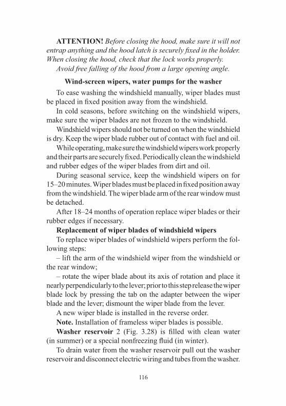
116
ATTENTION! Before closing the hood, make sure it will not entrap anything and the hood latch is securely fixed in the holder. When closing the hood, check that the lock works properly. Avoid free falling of the hood from a large opening angle.
Wind-screen wipers, water pumps for the washer To ease washing the windshield manually, wiper blades must be placed in fixed position away from the windshield. In cold seasons, before switching on the windshield wipers, make sure the wiper blades are not frozen to the windshield. Windshield wipers should not be turned on when the windshield is dry. Keep the wiper blade rubber out of contact with fuel and oil. While operating, make sure the windshield wipers work properly and their parts are securely fixed. Periodically clean the windshield and rubber edges of the wiper blades from dirt and oil. During seasonal service, keep the windshield wipers on for 15–20 minutes. Wiper blades must be placed in fixed position away from the windshield. The wiper blade arm of the rear window must be detached. After 18–24 months of operation replace wiper blades or their rubber edges if necessary. Replacement of wiper blades of windshield wipers To replace wiper blades of windshield wipers perform the fol-lowing steps: – lift the arm of the windshield wiper from the windshield or the rear window; – rotate the wiper blade about its axis of rotation and place it nearly perpendicularly to the lever; prior to this step release the wiper blade lock by pressing the tab on the adapter between the wiper blade and the lever; dismount the wiper blade from the lever. A new wiper blade is installed in the reverse order. Note. Installation of frameless wiper blades is possible. Washer reservoir 2 (Fig. 3.28) is filled with clean water (in summer) or a special nonfreezing fluid (in winter). To drain water from the washer reservoir pull out the washer reservoir and disconnect electric wiring and tubes from the washer.

117
Adjust the direction of water stream by changing the position of spraying nozzle balls with a needle inserted into the ball chan-nel (feed hole). When the spraying nozzle is clogged, disconnect the tube and air blow the spraying nozzle. To avoid failure of the washer pumps check the water level in the reservoir; 20 mm from the bottom is the lowest level permitted. Do not keep washer reservoirs turned ON for more than 10 s. ATTENTION! When switching on the washer of the tail gate door, there may be water feed delay up to 2.5 s.
Luggage compartment Luggage compartment has a pullout cover to protect the luggage. ATTENTION! Avoid placing objects on the cover. ATTENTION! No passengers are allowed in the luggage compartment during driving. ATTENTION! Tail gate door only opens from the outside.
Fig. 3.40. Under hood (fragment):1 — expansion tank of the engine cooling system; 2 — washer reservoir; 3 — auxiliary electric heater pump; 4 — air filter; 5 — engine cooling system radiator

118
CHAPTER 4. MOTOR VEHICLE PREPARATION UPON RECEIPT FROM THE MANUFACTURER
Dealers must sell the motor vehicle only after pre-purchase preparations, specified in the service book. If the motor vehicle was delivered to the sales point and traveled more than 100 kilometers (OST 37.001.082-82), all the prelimi-nary preparations for ferrying must be carried out as a part of the pre-purchase preparations.
CHAPTER 5. MOTOR VEHICLE RUNNING-IN Long-term and fail-safe service life of the motor vehicle depends on a greater extent on the run-in of the parts during the initial service period. The running-in kilometrage equals to 2,500 km. During the running-in period, observe the following rules: 1. Crankshaft rpm of engine must not exceed the 3/4 of the nominal rotational speed. 2. Do not exceed the motor vehicle nominal load. 3. Do not drive along the tough roads (deep mud, sand, steep inclines, etc.). 4. Do not haul the trailer. 5. Do not change the oils filled in the engine and units at the manufacturing plant. 6. Check and adjust the tension of the auxiliary unit drive belts if necessary, as they reach the maximum stretch during the running-in period. 7. Check the temperature of brake drums and discs and in case of raising the temperature, adjust the parking brake actuator or brake pedal free play. 8. Check the temperature of wheel hubs and in case of raising the temperature, loosen the tightness of bearing. 9. Check condition of all attachments and connections of pipes; eliminate leakages of oils, fuel, coolant and hydraulic fluid, if you find it.

119
CHAPTER 6. STARTING AND SHUTTING DOWN THE ENGINE GENERAL REQUIREMENTS
ATTENTION! It is strictly forbidden to start and warm up the engine indoors without good ventilation in order to avoid carbon monoxide poisoning. It is forbidden to start the gasoline engine with improperly installed high-voltage wires from the ignition coils to the spark plugs or low-voltage wires to the ignition coils. It can cause failure of the flywheel ring gear teeth and destruction of the starter. For reliable start of the engine, viscosity grade of the engine oil should correspond to the operating temperature range of the motor vehicle. Before starting the engine, check for the coolant in the engine cooling system, fuel, oil level in the engine crankcase and power steering tank. Shift the gearshift lever in neutral position. Remember that (in order to prevent the starter from acciden-tally switching on, when the engine starts) the ignition switch is equipped with the interlock, which allows the engine to be restarted only when the key returns to “0” position (Fig. 3.10). Switch on the starter for a maximum of 5 s. As soon as the engine starts, immediately release the ignition key, it will automatically return to “I” position. Warm up the engine. It is forbidden to increase a crankshaft speed for accelera-tion of the engine warming-up process. Do not drive a motor vehicle with a cold engine. The warmed up engine cooling fluid temperature shall be at least 60 °С.
ENGINE START
Starting a cold engine at -20 °C and above* 1. Turn on the ignition. It should activate the electric fuel pump, which can be heard when the engine turned off.
120
2. If the engine turns on after prolonged stop, it is recommended to wait until the electric fuel pump is switched off (about 5 s). 3. The system functions correctly if a malfunction indicator lamp (on the instrument cluster) switches on and off. If the mal-function indicator lamp continues to glow, it is required to detect and remove the malfunction (refer to “Diagnostics”). ATTENTION! If the motor vehicle has malfunctioning sys-tems (the malfunction indicator lamp continuously glows), it can cause the failure of the engine converter and oxygen sensor in exhaust gases. 4. Press the clutch pedal until stop. 5. Switch on the starter. 6. Release the key after starting the engine (turn off the starter). Try to start the engine not earlier than 15–20 seconds after the first attempt. When starting the engine, it is not recommended to press the throttle pedal. After starting the engine, its system will automatically set the fast idle speed to warm up the engine and gradually reduce it as the engine warms up. If the engine does not start after the third attempt, stop the ignition, detect and remove the malfunction. Starting a cold engine at temperature below -20 °C.* In order to ease the starting of cold engine at low temperature, preliminary warm up is required (by steam, hot air, etc.). The following sequence of operations is the same as in case of starting from cold at -20 °С and above.
Starting a hot engine The sequence of operations is the same as in case of starting from cold at -20 °С and above.
* If the motor vehicle is equipped with the starting pre-heater, it is recommended to use it at -10 °C and below

121
If the engine does not start after the third attempt, press the throttle pedal as far as it can go and turn on the starter for 2–3 seconds. The control unit will perform “Scavenging of the engine cylinders mode” function and then retry to start the engine.
Shutting down the engine In order to shut down the engine, turn the ignition key to the ‘0’ position. Before shutting down the engine, let it run for 1–2 minutes at low crankshaft speed.
CHAPTER 7. FEATURES OF DRIVING UNDER DIFFERENT ROAD, METEOROLOGICAL
AND CLIMATIC CONDITIONS The operation and service life of the motor vehicle depends to a great extent on the features of its driving. When driven correctly, the motor vehicle may run at a high middle speed and consume not much fuel when overcoming difficult road sections. It is recommended to put in the second gear when driving away from rest on a level section of a hard-surface road. In all the other cases, put in the first gear when driving away from rest. Disengage the clutch when putting in the gears and engaging the front axle: – disengage the clutch fast by pressing the clutch pedal as far as it can go; – engage the clutch smoothly, avoiding a quick release of the clutch pedal which results in jerking motion of the motor vehicle, and a slow engagement of the clutch with prolonged slipping; – do not keep the clutch disengaged on a stationary motor vehicle (waiting at a highway crossing, traffic light, etc.) when the gear is put in and the engine starts. It is recommended to use the neutral gear of the gearbox and the fully engaged clutch; – do not press the clutch pedal when the motor vehicle is in motion; – do not use the clutch slipping as a means of keeping the motor vehicle on steep inclines.

122
Put in the gears smoothly and without jerks. If it is impossible to put in the right gear when driving away from rest, then slightly release the clutch pedal and try to disengage the clutch and put in a gear again. Use the reverse gear only after bringing the motor vehicle to a complete stop. On slippery roads drive the vehicle evenly at low speed. Release the throttle pedal completely when braking with the engine. Brake the motor vehicle smoothly by gradually pressing the braking pedal. Any braking increases the wear of the tires and the fuel consumption. Avoid slipping of the wheels when braking, as it increases the braking path and wear of the tyres. In addition, sharp and hard braking could result in skidding of the motor vehicle. When driving the motor vehicle on off-road surfaces (sand, mud, snow etc.), slippery roads, steep inclines (more than 15°) and on other heavy road sections, do not overload the engine. In these conditions, engage the front axle in advance and use the reduction gear of the transfer case when driving through particularly difficult road sections. Engage and disengage the front axle in motion, and use the reduction gear of the transfer case only after bringing the motor vehicle to a complete stop. Overcoming steep inclines and descents. When driving on roads with steep inclines and descents, the driver should be very careful and have quick reflexes. Determine in advance the uphill gradient and shift to the required gear which would provide a required rim pull without shifting the gear. In order to overcome a steep incline, use the reduction gear of the transfer case and the first gear of the gearbox. Overcome steep inclines without stops and turns the the extent possible. Overcome short steep inclines with convenient access, and even road surface by speeding up without using the reduction gear of the transfer case and by shifting the gearbox to the second or third gear depending on the uphill gradi-ent. If for some reason it is impossible to overcome the incline, take all precautions and slowly descend by shifting to the reverse gear. Descend gradually, do not speed up the motor vehicle and

123
do not disengage the clutch. When overcoming steep descents, take measures to ensure a safe descent. Before overcoming a long descent (more than 50 m), determine its steepness, shift the gearbox and transfer case into the required gears to overcome it. Overcoming of such decents is performed by engine braking. WARNING! It is forbidden to overcome steep descents if the gears of the gearbox and transfer case are switched off or the clutch is disengaged. The rotational speed of the crankshaft should not be fast when making a descent, reduce the motor vehicle speed by gradually braking it. Overcome ditches, side ditches, and trenches at low speed with the front axle engaged in the direction perpendicular to the decline with regard to the motor vehicle dimensions defining its cross-country capability. Do not overcome an obstacle in a rush if an impact against the wheels is possible. When overcoming ditches and trenches, consider the possibil-ity of getting stuck due to wheels slips and vehicle cross-axling. In such situations activate the rear axle wheel differential lock in advance. Driving along muddy country roads and graded clay, and gumbo roads. When driving along clay and gumbo after heavy rain, the motor vehicle could slip off the road. Be careful when choosing the direction of motion. In order to prevent sideways skidding, choose relatively level ground while trying to move along the side-rut of the road if possible. It is very difficult to steer a motor vehicle on very wet graded roads with the steep grades and deep trenches. On these roads, drive carefully on the crest of the corrugation and at low speed. Driving along snowy or icy roads. Switch on the minimum gear and drive slowly. As the braking path of the vehicle on the slippery road is increased, it is required to increase the distance from the vehicle moving ahead.

124
When the motor vehicle sharply accelerates or brakes, the wheels could lose the traction to the road which may result in a road accident. In order to reduce the speed, use the engine braking; press the brake pedal only when the speed is sufficiently reduced. When driving down a slope, use the engine braking. Avoid the acceleration of the motor vehicle. WARNING! In order to ensure the safety of traffic, use the snow tyres when driving along snowy or icy roads. Overcome marsh-ridden sections by driving along a straight line without sharp turns and stops. Drive smoothly and without jerks. Move with engaged front axle and reduction gear of the transfer case, using the gear of the gearbox which would provide a required rim pull without slipping. In order to prevent the wheels from slipping and loosing adhesion with the turf, turn smoothly with a great radius, do not reduce the speed. Do not drive along the track made by the motor vehicle moving ahead. When overcoming sandy soils, drive smoothly without jerks and stops. Turn smoothly and with a great radius. Switch on the highest possible gear and engage the front axle, in order to overcome the sand drifts and short sand upgrades in a rush. Avoid the slipping of the wheels. Determine the road conditions preliminarily and switch on a required gear which would provide a required rim pull. Overcome a ford with great care. The motor vehicle can over-come a ford of a 500 mm depth with a hard bottom at low speed. Before overcoming a ford, check its bottom. Make sure that there are no deep pits, big stones, swampy grounds, choose and check the ground where the motor vehicle will enter the water and go out of the water, switch off the fog lamps. Overcome a ford slowly, without making waves in front of the motor vehicle, in the first or second gear of the gearbox, engaging the front axle and the reduction gear of the transfer case. Avoid maneuvering and sharp turns.
125
After fording, as soon as possible but not later than on the same day, check oil in all units. Change oil in units where water is detected. There is some water in the oil if its color is changed. Lubricate all grease fittings of the chassis until the fresh grease appears. After every fording, partly engage the clutch and partly apply the brakes several times in order to dry the clutch facings and brake shoe linings. If the engine stops when fording, try to restart the engine by means of the starter two to three times. If the engine does not start, the motor vehicle should be immediately removed from the water by all means. If some water is penetrated to the units of the vehicle after the removal, it is not recommended to drive the motor vehicle. Tow the motor vehicle to a service station. The motor vehicle can move along snowy surfaces of a 350 mm depth. Steer the motor vehicle in the same manner as when moving on swampy grounds. When driving on friable snow, apply the same rules as when driving on sand surfaces.
CHAPTER 8. TOWING OF THE MOTOR VEHICLE
The front and rear parts of the frame (Fig. 8.1) are equipped with towing eyes for flexible towing. Before towing, turn on the ignition (position I, Fig. 3.10) and light alarm. When towing, check the tension of the rope. Tow the motor vehicle smoothly, without jerks. The towing of a trailer is possible only if the vehicle is equipped with a ball-type tow hitch. WARNING! Remember that when the engine turns off, the forces required for steering input and motor vehicle braking increase significantly. Strictly follow the requirements listed in “The Highway Code” when towing. If the brake or steering system is broken, it is forbidden to drive or tow the motor vehicle with a tow rope. In this case use the two wheel towing or tow truck service. It is strictly forbidden to tow the motor vehicle using the ball-type tow hitch!

126
CHAPTER 9. VEHICLE MAINTENANCE The vehicle maintenance volume and frequency is given in the warranty and service book. The present manual contains the methods of motor vehicle maintenance and adjustment of its units and also the operations which should be carried out in the intervals between the maintenance actions in accordance with the warranty card of the service book. Tightening torques of the main threaded joints are shown in Annex 2 of the present Manual.
DAILY MAINTENANCE
1. Visually check the motor vehicle configuration, the condition of the body, glasses, rear view mirrors, trim packages, license plates, painting, door locks, wheels, and tires. Eliminate the detected defects. Inspect the parking lot of the motor vehicle to make sure there are no fuel, oil, coolant or brake fluid leakages. Eliminate the detected leakages. Check and replenish to the standard, the amount of cooling fluid, oil in the crankcase, braking fluid, and fuel. 2. Check the functioning of the steering system, brake systems, lighting devices, light, and sound alarms, windscreen wiper. Elimi-nate the detected defects.
Fig. 8.1. Towing eyes:1 — front eyes; 2 — rear eyes.
127
3. Fill the windshield washer fluid tank. Water is allowed for use in warm season. 4. If the motor vehicle was operated in extremely dusty condi-tions or crossed fords and country road sections covered with the mud, check the condition of the filter element of the engine air filter and replace it if necessary. 5. After a trip, wash the vehicle if operated on dirty or dusty roads.
VEHICLE MAINTENANCE EVERY 500 KM
1. Check and adjust the tire air pressure as required. 2. Check and tighten the wheel bolts after the first 300–500 km (if necessary).
SEASONAL MAINTENANCE
Seasonal maintenance is performed twice a year (in spring and autumn) and, if possible, combines with the next maintenance in accordance to the warranty card of the service book.
Prior to the summer season operation 1. Remove the oil pump cover and check the condition of the oil pump drive gears. 2. Check the operation of the window wiper and washer. Elimi-nate the defects. 3. Replace oils in the units with summer (all-season) grade oils specified in the lubrication schedule.
Prior to the winter season of operation 1. Check density of fluid in the engine cooling system and bring to the required value (1.075–1.085 g/cm3 at 20 °С) if necessary. 2. When filling the washer reservoir with the water, pour off the water. 3. Check the operation of the interior heating and ventilation system. Eliminate the defects. 4. Replace oils in the aggregates with winter grade oils speci-fied in the lubrication schedule.

128
ZMZ-40906 ENGINE
Engine Suspension During operation, check tightening of threaded joints of the front and the rear engine suspensions (see Appendix 2) and condi-tion of the mounts. No delamination and breakage of the engine mounts is allowed.
Engine cylinder head During operation of the engine, the cylinder head bolt tighten-ing is not required. Perform the tightening only when the engine is cold, if necessary. In order to provide a tight and even contact of the cylinder head bolt with the gasket, perform the tightening in a sequence shown in Fig. 9.1. in two steps. Tighten the bolts evenly using a torque wrench (refer to Appendix 2).
Fig. 9.1. Sequence of the cylinder head bolt
tightening.
Engine gas distribution mechanism Camshaft drive is a two-stage chain. Chain tension is provided for by hydraulic tensioners. WARNING! Do not take the hydraulic tensioner out of the chain cover to prevent disengagement of the piston with the casing caused by the wrap spring. The valves are driven from the camshafts directly via the hydraulic pushers.Using the hydraulic pushers eliminates the need for clearances adjustment.
Engine lubrication system The engine should be stopped immediately when a lubrica-tion system malfunction is registered.

129
Regularly check the oil in the crankcase and fill it up as required. Make the check before starting the engine. When checking the oil level after the engine stops, it is necessary to wait for at least 15 minutes to allow the oil to drain into the crankcase. The vehicle must be parked on a horizontal site. The oil level shall be between MIN and MAX oil level gauge marks 10 (Fig. 9.2). In case of fre-quent cross-country road trips, keep the oil level near the “MAX” mark, not exceeding it. The volume of oil to be added to the engine between MIN and MAX is 1 liter. Engine oils of different grades and different manufacturers may not be mixed! If the engine oil of another grade or manufac-turer is to be poured, you must flush the lubrication system with washing oil. The washing oil shall be selected in accordance with the recommendations of the manufacturer of the newly poured oil.
Fig. 9.2. Engine ZMZ-40906 (left side view):1 — coolant from radiator to water pump supply pipe; 2 — connection hoses; 3 — thermostat housing; 4 — control unit coolant temperature sensor; 5 — coolant branch pipe from thermostat to radiator; 6 — critically low oil pressure sensor; 7 — crankshaft position sensor connector; 8 — absolute pressure and temperature sensor; 9 — ignition coils; 10 — oil level indicator; 11 — engine elevation rear bracket; 12 — exhaust manifold screen; 13 — exhaust manifold; 14 — flywheel; 15 — clutch; 16 — oil charger; 17 — clutch charger booster; 18 — oil purge plug.

130
When changing the engine oil, replace the oil filter. Drain the used oil from the engine crankcase immediately after a journey while it is still hot. In this case, the oil pours out quickly and completely. Remove the oil filter 10 (see Fig. 9.3) by turning it counter-clockwise. When installing a new filter, make sure that the rubber O-ring is in proper condition and lubricate it with engine oil, turn the filter until the O-ring touches the plane on the engine block and then tighten the filter with a 3/4 turn. Make sure no oil leak exists. With the engine warm and the lubrication system intact, the emergency oil pressure warning lamp may be on at idle, but it shall go out immediately after increasing the crankshaft rpm. It is recommended to flush the engine lubrication system after each two oil changes. For that purpose, drain the used oil, fill in special flushing oil (VNIINP-FD) 3-5 mm over the “MIN” mark on the oil level indicator and let the engine run for 10 minutes.
Fig. 9.3. Engine ZMZ-40906 (right side view):1 — coolant to heater branch pipe; 2 — heater coolant discharge tube; 3 — knock sensor; 4 — fuel pipeline flanged socket/union nipple; 5 — common rail with injectors; 6 — “-” KMCUD wire connection pin; 7 — upper hydraulic tensioner cap; 8 — engine elevation front bracket; 9 — lower hydraulic tensioner cap; 10 — oil filter; 11 — oil pump drive cap; 12 — start motor; 13 — gear installation pin.

131
Then drain the flushing oil, replace the oil filter and pour in clean engine oil. If the flushing oil is absent, the flushing can be carried out using pure engine oil.
Engine crankcase ventilation system During engine breather system maintenance remove valve cap 4 (Fig. 9.4), ventilation hoses and tubes, vacuum valve cap 3, the valve membrane and spring and clean the removed parts. Clean the holes of valve cap ventilation necks, holes 7 of separated oil drain, sensing hole 8 in the vacuum valve case and venting holes in the vacuum valve cap. The oil baffle 5 shall be flushed mounted on the valve cap. Check the membrane for damage and breakage. When re-assembling, ensure tightness of connections. ATTENTION! The engine may not be operated if the crankcase ventilation system is not tightly sealed and with opened oil filler. This results in an increased escape of oil with crankcase gases, and contamination of the environment. To prevent the crankcase ventilation system from de-pressurization, you must close the oil filler cap tightly, as far as it can go, and install the oil level indi-cator against stop.
Fig. 9.4. Engine crankcase of ventilation:1 — receiver; 2 — ventilation tube connects depression valve to receiver; 3 — depression valve; 4 — valve cap; 5 — oil reflector; 6 — blow-by gas flow; 7 — blow-by gas separated oil drain orifice; 8 — depression valve orifice; 9 — engine injection system air supply tube with reverse valve.

132
Engine cooling system (Fig. 9.5) WARNING! Coolant is poisonous. Keep it in a tightly closed container. While using it, obey the following rules: – avoid any operations as a result of which the liquid can enter into the mouth cavity; – do not let the fluid dry out on the skin; wash it off with soap and warm water; – flush the spilled fluid with water, air the room; – take off the clothes, contaminated with the fluid, dry it outside the room, and wash it. Take due care when opening the cap of the expansion tank of the engine cooling system to avoid a scald. For cooling liquid, use a low temperature freeze fluid TOSOL-A40M, OG-40 Lena or OG-40 TOSOL-TC.
Fig. 9.5. Engine cooling and heating system scheme:1 — cabin heater radiator; 2 — heater radiator connection hoses; 3 — engine; 4 — thermostat; 5 — control unit coolant temperature sensor; 6 — expansion tank; 7 — expansion tank plug; 8 — radiator assembly; 9 — motor fan; 10 — discharge plug; 11 — fan; 12 — fan drive; 13 — pump; 14 — crankcase discharge plug; 15 — additional heater motor pump

133
At the ambient air temperature minus 40 °С use the low freeze point fluid TOSOL-A40M, OG-40 Lena or OG-40 TOSOL-TC. The cooling fluid operating temperature shall be within 80–110 °С. Short-time (maximum of 5 minutes) engine run is allowed at cooling fluid temperature up to 120 °С. When the cooling fluid overheat warning lamp turns on, you must immediately identify and eliminate the cause of overheating. As required, check the coolant level in expansion tank 1 (Fig. 3.40), especially if an additional heater is installed. The fluid level should be between the “min” and “max” markings. Since a cooling fluid has a high thermal expansion coefficient and its level in the expansion tank varies significantly depending on the temperature, check the level at the system temperature of plus 15–20 °С. If the cooling fluid decreases in the expansion tank within a short period time or after moderate mileages (up to 500 km), check the cooling system tightness and, after elimination of leaks, add the same cooling fluid into the expansion tank. Every three years or after every 60,000 km (depending on which happens first) purge the cooling system and refill the coolant. Purge the cooling system as follows: – fill the system with pure water, start the engine, let it work until warmed up, shut the engine down and drain water; – repeat the above operation. It is impossible to fill the system completely with the neces-sary coolant volume without engine launch due to the existence of air in the interior heaters and connecting hoses. Fill the system as follows: – set the additional heater (if installed) switch 7 (Fig. 3.11) to the ON position; – fill the cooling system with a coolant via an expansion tank inlet 3–4 cm beyond the MIN mark; – start the engine, add the cooling fluid to the cooler upper tank when its level decreases;
134
– stop the engine, let it cool down, raise the cooling fluid level in the expansion chamber to the standard and close the expansion chamber plug; – run 2–3 cycles of the engine warm-up — cool-down and raise the cooling fluid level again in the expansion chamber to the standard. To drain the fluid from the engine cooling system open the expan-sion tank plug, unscrew teh heat exchanger outlet plug 10 (Fig. 9. 5) and unscrew cylinder head cap 14. When draining, set the additional heater (if installed) switch 5 (Fig. 3.11) to the ON position. The generator and cooling system pump drive belt tension (Fig. 9.6.) is provided by an automatic tension mechanism 2. In the operation process, the automatic tension mechanism does not require servicing or adjustment. Fan and steering system hydraulic pump drive belt tension 15 (Fig. 9.6) is performed by displacing pump 12, for which it is neces-sary: to loosen bolts 13, adjust the drive belt tension by adjustment bolt 14 and move the pump along the rails. Tighten bolts 13. In motor vehicles equipped with an air conditioner, the aggregates drive is performed by the same belt. Its tension is adjusted automati-cally (Fig. 9.7). It is necessary to check belt condition during the operation process. Upon detection of its substantial looseness, the GUR pump placement adjustment is possible by bolt 9, to continue using the stretched belt. The GUR pump is fixed by bolts 8. Fan drive clutch. In case the clutch does not switch on and off properly, the engine can overheat. Check up is to be done at a specially equipped UAZ workshop. Keep the external surface of the clutch clean. Electric fan is installed on the cooling system radiator assembly at the front. It turns on and off automatically.
Gas exhaust system WARNING! Working temperature of neutralizer and gas exhaust system parts is 400-800 °С. The motor vehicle may not be operated without neutralizer protecting screens. While driving the motor vehicle and while parked, ensure the exhaust system does not contact any inflammable materials (e.g. dry grass).

135
Exhaust gas leaks from the exhaust system connections fitted with gaskets are not allowed and shall be eliminated on the first occasion. Tighten heat attached nuts (see Annex 2) after rinsing threaded connections with specific fluids. When the feed system or the ignition system is faulty, a lot of unburnt hydrocarbons ingress into the neutralizer, due to this the temperature in the neutralizer can rise above the admissible limit (750–800 °С) and the neutralizer will fail. Therefore, special attention shall be paid to the operation of the feed system and the ignition system. Three-cylinder-based operation of the engine is prohibited even for a short period of time.
Fig. 9.6. Aggregates drive belt tension1 — synchronization sensor; 2 — automatic tension mechanism; 3 — alternator and water pump drive belt; 4 — alternator pulley; 5 — inlet pipe; 6 — receiver; 7 — throttle assembly with throttle position sensor; 8 — oil filler cap; 9 — valve cap; 10 — fan pulley; 11 — water pump pulley; 12 — steering system pump pulley; 13 — steering system pump attachment bolt; 14 — adjusting bolt; 15 — fan and steering system pump drive belt; 16 — crankshaft pulley damper.

136
Injection system with microprocessor fuel supply control and ignition (Figs. 9.2, 9.3)
Precautions 1. Before disassembling and assembling any parts or cables of steer-ing system, disconnect the mass wire from the accumulator battery. 2. The engine may not be started if the rechargeable battery and the ground wire between the engine and the body are not con-nected reliably. 3. The rechargeable battery may not be disconnected from the motor vehicle in-vehicle network while the engine is running. 4. While being charged from an external source, the recharge-able battery must be disconnected from the in-vehicle network. 5. The control unit may not be exposed to temperatures above 80 °С, e.g. in an oven dryer.
Fig. 9.7. Accessory drive belt:1 — automatic tensioning mechanism; 2 — auxiliary Idle pulleys/guide rollers; 3 — conditioner compressor pulley; 4 — alternator pulley; 5 — fan pulley; 6 — water pump pulley; 7 — steering system pump pulley; 8 — steering system pump attachment bolt; 9 — adjustment bolt; 10 — belt; 11 — crankshaft damper-pulley.

137
6. Before arc welding operations, disconnect the battery wire and control unit connection. 7. To prevent rusting of pins during vapour cleaning, do not direct the nozzle to the system components. 8. The control systems’ electronic components are designed for very low voltage and are vulnerable to electrostatic discharges. 9. The fuel supply system from electric gas/fuel pump to fuel pressure regulator at running engine is under pressure at 4 kgc/cm2. WARNING! The fuel line joints may not be loosened or tight-ened with the engine running or immediately after its stop. 10. Fuel pump electric motor is cooled by the passing fuel current, thus to avoid its damage do not turn on the electric fuel pump ‘on a dry’, when the right fuel tank is empty.
Feed System WARNING! The motor gasoline and its vapours are toxic and flammable. Observe the following rules: – observe fire safety rules; – avoid any operations as a result of which the liquid can enter into the mouth cavity; – do not let the fluid dry out on the skin; immediately wash it off with soap and warm water; – cover the spilled gasoline with sand or chips, brush it off and dispose of it, ventilate the room; – remove clothing contaminated with fuel, dry it outside the room and launder. WARNING! Use only recommended unleaded gasoline. Lead from leaded gasoline causes failure of the exhaust gas oxygen sensors and the neutralizer. Electric fuel pump with fuel tank level gage (submersible module) is installed in the tank. Tube neck of the fuel tank filler pipe is deaf, and provides a hermetic seal.

138
Plastic (multilayer) fuel tank 1 (Fig. 9.8).Fuel tank main-tenance includes submersible module flushing (clogging of the submersible module filter), flushing of the tank (presence of dirt and mechanical admixtures in the fuel tank). Check from time to time the reliability of the tanks fastening and, if necessary, tighten the fastening bolts. Fuel tanks must be dismantled from the vehicle in order to flush them. Prior to dismantling the tanks from the motor vehicle, do the following: – disconnect accumulation battery; – loosen bolts of the fuel tank bands and lower the tank; – disconnect the cable from the electric fuel pump (submersible module) and isolate it; – disconnect the polyamide pipes of the high pressure tube; – loosen filling pipe collar and take off the filling pipe from the fuel tank neck, disconnect the steam-sleeve from the fuel tank branch pipe or unscrew the filling pipe bolts in the flap frame. Then unscrew coupling band pins, turn collars down so as not to impede tank lowering and remove tank. Install tank in reverse order. Submersible module 5 (Fig. 9.8) includes electric fuel pump, gauze filter, intake camera with jet pump, fuel supply union to the preheater, the pressure controller and the fuel tank level gage. At mounting of the tank, check and clean fuel pump pins and connections to the onboard power supply. Pay special attention to the reliability of the ground connection. Try to avoid fully running out of fuel, as it can affect the assemblies. When overcoming the steep inclines, there must be at least 20 liters of fuel in the right-side tank. Clogging of the strainer fuel module, final fuel filter, presence of dirt and mechanical admixtures in the fuel tank manifest first of all in deterioration of the pumping of the fuel from the left-side tank into the right-side one, unstable engine operation at high loads and degradation of the motor vehicle performance. If such signs arise, seek help from a service station in order to prevent the fuel priming pump failure.
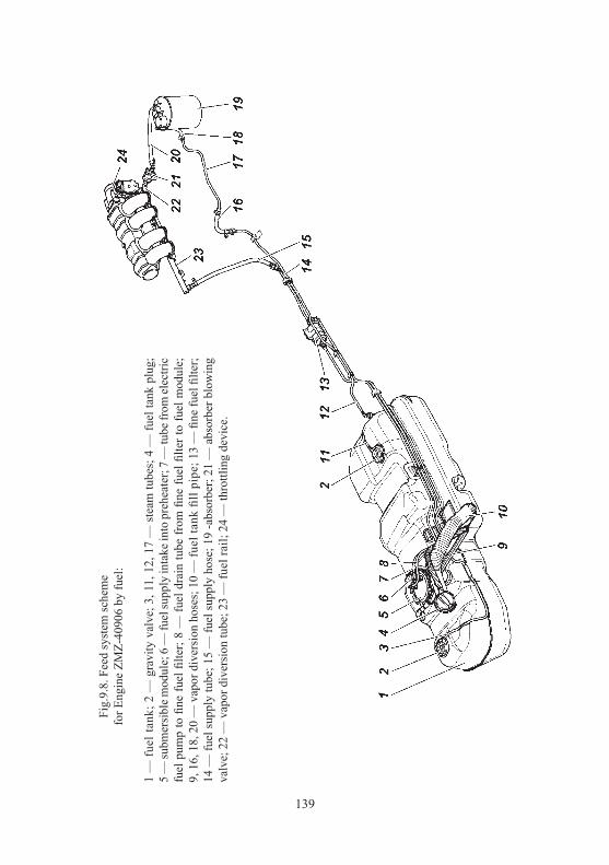
139
Fig.
9.8.
Fee
d sy
stem
sche
me
for E
ngin
e ZM
Z-40
906
by fu
el:
1 —
fuel
tank
; 2 —
gra
vity
val
ve; 3
, 11,
12,
17
— s
team
tube
s; 4
— fu
el ta
nk p
lug;
5
— su
bmer
sibl
e mod
ule;
6 —
fuel
supp
ly in
take
into
pre
heat
er; 7
— tu
be fr
om el
ectri
c fu
el p
ump
to fi
ne fu
el fi
lter;
8 —
fuel
dra
in tu
be fr
om fi
ne fu
el fi
lter t
o fu
el m
odul
e;
9, 1
6, 1
8, 2
0 —
vap
or d
iver
sion
hos
es; 1
0 —
fuel
tank
fill
pipe
; 13
— fi
ne fu
el fi
lter;
14 —
fuel
supp
ly tu
be; 1
5 —
fuel
supp
ly h
ose;
19
-abs
orbe
r; 21
— a
bsor
ber b
low
ing
valv
e; 2
2 —
vap
or d
iver
sion
tube
; 23
— fu
el ra
il; 2
4 —
thro
ttlin
g de
vice
.

140
Note. At atmosphere temperature below 0 °С clogging symptoms can be caused by water freezing in fuel system. When detecting water in fuel purge fuel and rinse fuel tanks with pure fuel and fine fuel filters are to be replaced. Leakage in couplings should be eliminated by replacing faulty components. Upon completion of any fuel system maintenance operations, related to tightening of connections, removal or replacement of parts and assemblies, the system hermetic-tightness must be checked as follows: – make sure the filler neck plug is securely tightened; – fuel tubes shall be installed until “click” of the quick coupler’s locking spring; – start the engine running idle and check the system visually. Fuel leaks or the fuel system components wetting may not be allowed. In the course of vehicle operation, pay attention to the following: – a strong smell of gasoline within the vehicle’s salon, engine compartment in locations of passage of fuel and steam hoses and tubes, if this occurs — check the hermetic-tightness of joints, con-dition of the adsorption container (absence of cracks and damage, serviceability of the adsorption container’s purge valve); – operability of the evaporative emission control system (the absorber and the fuel tank valve). Any failure of these elements leads to fuel supply system failures. Damaged components shall be replaced. Accelerator pedal drive. The motor vehicle is equipped with an accelerator pedal electronic module. Accelerator pedal is made of plastic. Full pedal stroke equals 48,7 mm and is provided with stable design and is not regulated. Air filter. After every 30,000 km of total kilometres logged and after engine capacity reduction, replace filter element. The filter element shall be replaced as follows: – loosen collars and remove angle, and resonator hoses from air filter; – unscrew collar nut 4 (Fig. 9.9), remove collar and air filter; – unscrew nut 7 and take cover 1 with the filter cartridge 5 out of the filter housing; – unscrew nut 6 and remove filter element; – install a new filtering element, compose and install air filter.

141
Fuel supply and ignition control system To connect the engine control system automated external diagnostics and programming devices, the data link connector covered with protective lid is installed under the hood on the front bodywork panel (Fig. 9.10). Control unit is installed under the motor vehicle house-coat hood on the right hand side wall.
Diagnostics Serviceability of the engine control system and the injection system depends on the mechanical and hydromechanical systems. Several deviations leading to faults can be mistaken for the control system electronic part malfunctions such as: – low compression; – deviation of gas distribution phases caused by an incorrect assembly of engine components;
Fig. 9.9. Air filter:1 — air filter cap; 2 — sealing spacer; 3 — filter housing; 4 — filter attachment collar; 5 — filtering element; 6 — nut; 7 — nut; 8 — air duct
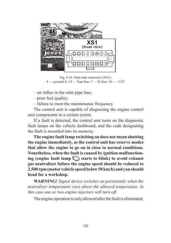
142
– air influx in the inlet pipe line; – poor fuel quality; – failure to meet the maintenance frequency. The control unit is capable of diagnosing the engine control unit components to a certain extent. If a fault is detected, the control unit turns on the diagnostic fault lamps on the vehicle dashboard, and the code designating the fault is recorded into its memory. The engine fault lamp switching on does not mean shutting the engine immediately, as the control unit has reserve modes that allow the engine to go on in close to normal conditions. Nonetheless, when the fault is caused by ignition malfunction-ing (engine fault lamp starts to blink) to avoid exhaust gas neutralizer failure the engine speed should be reduced to 2,500 rpm (motor vehicle speed below 50 km/h) and you should head for a workshop. WARNING! Signal device switches on persistently when the neutralizer temperature rises above the allowed temperature. In this case one or two engine injectors will turn off. The engine operation is only allowed after the fault is eliminated.
Fig. 9.10. Data link connector (XS1):4 — ground; 6, 14 — Sup-line; 7 — K-line; 16 — +12V
XS1(front view)

143
Diagnostic lamp operation In operating mode with ignition started and engine inoperative the diagnostic lamp turns on and goes out after the engine start up. If the diagnostic lamp is on with the engine operating, the system and engine require maintenance as soon as possible. When ignition faults are present while engine is operating, the diagnostic lamp starts to blink and glows on while neutralizer exceeds the allowed temperature.
Clearing fault codes The memory storing the fault codes can only be cleared using the scanning tester. If the rechargeable battery turns off, the control unit self-learning parameters are not lost and can be only cleared using the scanning tester.
Pre-starting heater+ All necessary information about heater operation and maintenance is in the manufacturer’s manual, enclosed in the motor vehicle.
DRIVING SYSTEM
At slow speed, in gears 1 and 2, in acceleration-deceleration regime, an audible knock in the form of short clicks may occur in the driving system. When moving at higher gears of the gearbox and the transfer case at speed higher than 60 km/h in engine braking regime, as well as during free running (neutral position of the gearbox), noise in the driving system in the form of a slight low-frequency hum may occur; During brisk acceleration of the motor vehicle, a slight knock may occur during selection of air gaps in spline coupling of the driving system. Upon engine braking a slight knock may occur during selection of air gaps in spline couplings of the driving system. During free running and subsequent brisk acceleration of the motor vehicle, a slight knocking of synchronizers rings of the gearbox may occur.

144
Clutch WARNING! Brake fluid is poisonous. Keep it in a tightly closed container. While working with it follow these rules: – avoid any operations as a result of which the liquid can enter into the mouth cavity; – do not let the fluid dry out on the skin; wash it off with soap and warm water; – flush the spilled fluid with water, air the room; – take off the clothes, contaminated with the fluid, dry it outside the room, and wash it. The level of the fluid must be 15–20 mm lower than the upper edge of the reservoir 2 (Fig. 9.11). The clutch pedal position is adjusted by clutch master cylinder push rod 5 length change. Clutch pedal full travel should be 130±10 mm. Free travel (5–30 mm) is clutch design feature and is not adjusted. Incomplete clutch release and pedal softness indicate air pres-ence in the hydraulic system. Perform system bleeding via clutch release cylinder valve 2 (Figs. 9.12, 9.13) following the hydraulic brake system bleeding instruction. Tightening torque of clutch plastic cylinder bleeder unit must be 0.5–0.6 kgf•m.
Fig. 9.11 Drive of master cylinder clutch release:1 — tank cap; 2 — tank housing; 3 — master cylinder housing; 4 — safety cover; 5 — push rod; 6 — nut; 7 — push rod sleeve; 8 — clutch release pedal; 9 — clutch switch off pedal.
145
Gearbox Regularly check threaded couplings (see Annex 2). If a leak is detected, find out the reason and replace the defec-tive parts (spacers, collars). To check oil level, screw out plug 5 (see Figs. 9.12, 9.13). The oil level should reach the filler orifice lower edge. Upon oil replacement, drain oil immediately following the motor vehicle shut-down while the aggregate is hot. Do not forget to unscrew plug 5. Following plug 6 installation, replace spacer.
Transfer case Regularly check threaded couplings (see Annex 2). If a leak is detected, find out the reason and replace the defec-tive parts (spacers, collars). To check oil level, screw out plug 9 (Fig. 9.12) or 8 (Fig. 9.13). The oil level should reach the filler orifice lower edge. Upon oil replacement, drain oil immediately following the motor vehicle shut-down while the aggregate is hot. For this it is necessary to: – wipe dry fill and drain plugs; – place a vessel under transfer case; – pull drain and fill plugs out; – let oil drain; – replace and tighten drain plug at 6.0–6.5 kgs m momentum; – refill oil until overflow via filler plug orifice; – replace and tighten drain plug at 6.0–6.5 kgs m momentum; WARNING! Use the same oil brand for Dymos gearbox and Dymos transfer case (see Annex 3). Do oil check and refill in gearbox and dispense box simultaneously. WARNING! Different oils are used in the gearbox ‘Dymos’ and in the transfer case PJSC UAZ (see Annex 3), blending is not permitted.

146
Fig. 9.12. Dymos 5-step gearbox, Dymos transfer case and clutch release cylinder:
1 — clutch release cylinder; 2 — transfer valve; 3 — gearbox; 4 — transfer case; 5 — gearbox housing filler plug; 6 — gearbox housing drain plug; 7 — transfer case housing drain plug; 8 — motor drive; 9 — transfer case housing filler plug.
Fig. 9.13. Dymos 5-step gearbox, UAZ transfer case and clutch release cylinder:
1 — clutch release cylinder; 2 — transfer valve; 3 — gearbox; 4 — transfer case; 5 — gearbox housing filler plug; 6 — gearbox housing drain plug; 7 — transfer case housing drain plug; 8 — transfer case housing filler plug.

147
WARNING! Transfer case ‘Dymos’ malfunction signal device turns on after switch starting and turns off when the system
in normal condition. When signal device is turned on, go to the nearest authorized service center for four-wheel drive check up.
Propeller shafts Regularly check threaded couplings (see Annex 2). The spline coupling is lubricated through grease fitting 1 (Fig. 9.14), which is screwed into the slip yoke, and the needle bearings are lubricated through grease fitting 2 on the crosses. Lubricate the needle bearings until the grease shows up from under the working edges of the cross oil seals. Applying solid oil or its mixtures for lubrication of the needle bearings can lead to their premature failure. Do not apply too much grease to the splined couplings, as it would bleed through the spline coupling, and that would provoke a premature failure of the oil seals and could eject the plug of the slip yoke. Use a special tip to be fitted on the grease gun to lubricate the knuckles.
Fig. 9.14. Propeller shaft: a — without intermediate strut; b — with intermediate strut.1 — grease-pump for spline coupling lubrication; 2 — grease-pump for needle bearings lubrication of the joint.

148
The motor vehicle may be equipped with non serviceable pro-peller shafts (without grease fitting). If this is the case, regularly check shaft coupling pleated sleeve. Following pleated sleeve damage, apply to the service centre for replacement.
Driving axles Check the oil level in the housing, it should reach the lower edge of the filler orifice. Drain the oil through orifice 2 (Fig. 9.15) at the bottom of the housing by screwing out filler plug 1. Axial clearance over 0.05 mm in the bearings of the axle drive pinion is not permitted, as greater clearance would provoke pre-mature gear teeth wear and that could result in an axle jam. Check the axial clearance in the bearings by swinging the drive pinion by universal-joint flange. Axial clearance in the differential bearings of the final gear is not allowed. Check the clearance by swinging of the drive pinion when the housing cap is removed. If a gap is detected, the axle should be adjusted. The axle adjustment is a labor-intensive operation requiring specific skills and instrument, that is why we recommend to conduct axle adjust-ments only at a service station. During inspection of the steering knuckles, check the service-ability of adjusting bolts 1 (Fig. 9.16) and steering stop bolts 3. The value of steering angle B of the right wheel to the right,
Fig. 9.15. The front axle:1 — filler plug; 2 — drain plug; 3 — safety valve; 4 — lower pin nut.

149
Fig. 9.16. Adjustment of the wheels steering angle:
1 — steering stop bolt; 2 — lock-nut; 3 — steering stop.
and of the left wheel to the left should be within the limits of 31–32°. The increased steering angle of the wheels results in the contact of the wheel with the suspension parts. It is not required to add grease into the spherical pins and into the ball struts during operation. The grease in the units is replaced during maintenance. Adjustment of steering knuckle pins 2 (Fig. 9.17) tightening at works is carried out at pre-load along the common axle shaft of the pins. During operation of the vehicle, pay special attention to the condition of the tightening of the steering knuckle pins. At the wear of the interacting spherical surfaces of liners 3 or pins 2 the pre-load disappears and the air gap appears along the common axle shaft of the pins.To remove the air gap tighten clamping bush 10. Operating the front driving axle with gaps in the pins units can lead to a premature failure of the liner of the upper pin. It is easier to tighten clamping bush 10 of the lower pin while in operation: – unscrew nut 13; – remove shield 12 with spacer 11; – using the special wrench tighten clamping bush 10 to remove the air gap (hit the threaded end of the pin with a copper hammer beforehand); – by turning the wrench by 10–20°, tighten this bushing to obtain a preliminary tension along the common axle shaft of the pins; – install bracket with a spacer; – tighten nut (see Annex 2). Warning! Tightening torque excess will cause lower pre-load and pin unit failure.

150
Fig. 9.17. Steering knuckle and wheel hub:1 — steering knuckle housing; 2 — pin; 3 — pin liner; 4 — spring; 5 — outer O-ring; 6 — inner O-ring; 7 — joint; 8 — ball strut; 9 — outer oil seal housing; 10 — clamping bush; 11 — spacer; 12 — plate; 13 — nut.
The driving force of ball strut 8 (or housing 1 of the steering knuckle, if the ball struts were not disconnected from the hous-ing of the axle shaft) in any direction relative to the common axle shaft of the pins should be within the limits of 10–25 N∙m (1.0–2.5 kgs∙m) considering the removed O-rings 5, 6 and joint 7 of the steering knuckle. In case the control parameter is not reached, tighten the clamp-ing bush once again by turning the wrench by 10–20° and tighten the nut 13 with the specified torque. In case air gap persists following threaded bush tightening, contact UAZ service to replace pins units liners.
151
CHASSIS
Suspension WARNING! Shock absorber disassembly is strictly forbidden to avoid accidents. The motor vehicle operation at malfunctioning or missing shock absorbers and worn out suspension joints is strictly prohibited. Front and rear shock absorbers are not interchangeable. Hydraulic shock absorbers are not served and repaired. Upon shock absorbers replacement, replace axle assembly. Replace suspension pin joints in case of knocks, squeaks and/or rubber bundle. Do not operate the vehicle with track control arm and/or tie rod deformation. Upon pin joints replacement the complete nuts tightening (see Annex 2) is to be performed on the wheeled motor vehicle. Upon spring installation, the complete tightening (see Annex 2) of ladder nuts, front axle spring nut and spring shackle bolt nuts is performed at motor vehicle weight load.
Wheels and tires WARNING! Worn out and damaged tyres, excessive or insufficient air pressure in them, deformed discs or weakening of fastening of wheels can cause an accident. Regularly check tyres condition and air pressure, discs condition and safe mounting. Since tyres of different models (tread patterns) may have dif-ferent sizes and stiffness performances, use identical tyres for all wheel discs.
WARNING! Using tyres and wheels of deprecated dimen-sions can lead to uneven tire wear, deterioration in motor vehicle handling, increased fuel consumption and braking distance, the appearance of vibration on the steering wheel and cause mal-function of the ABS system (if any), which in turn can lead to a serious accident. Use only identical tyres of dimensionality and manufacturer for all wheels. Otherwise driving system components can be damaged.

152
WARNING! It is not recommended to install tires the size of which differs from those installed at the manufacturing plant. At changing tires, the size of which differs from the installed ones, to ensure correct ESP and speedometer operation, it is neces-sary to save the new tire size in the ESP electronic control unit memory. For this you must contact the UAZ LLC service station. (the addresses of service stations are listed in the service book). For more uniform tightness, tighten the nuts while observing the rule — through one nut . Final tightening is carried out on the motor vehicle standing on wheel discs (see Annex 2). Check inflation pressure in cold tires. If intensive uneven wear of the front wheel tyres is detected, check and adjust the toe-in of the front wheels and the air gaps in the pins units. Checking and wheels toe-in adjustment using on a process-specialized stand. Carry out wheels toe-in adjustment at a normal tyre air pressure. Adjust wheels toe-in adjusting steering trapezoid rod length by nozzle 2 rotation (Fig. 9.18) after prior loosening of left-handed thread counter nuts 1and right-handed counter nuts 3. To complete adjustment, tighten counter nuts (see Annex 2). After every 15,000 km of total kilometres, carry out a wheels swap for even tyre wear. Follow the same side rule: swap the front and rear wheels on the same side. Do not use a spare wheel. When swapping the wheels, ensure they are balanced. UAZ Patriot spare wheel with a plastic container is attached to the back door bracket by three nuts, depending on the package.
Fig. 9.18. Steering trapezoid tie rod:1 — left thread nut; 2 — flanged socket; 3 — right thread nut; 4 — joint.

153
UAZ Pickup and UAZ Cargo spare wheel are placed at the rear underbody part and should be securely fixed to the hold by a sector. Move the wheel away from exhaust manifold to a 40 mm air gap prior to wheel adjustment to avoid a tyre burnout from exhaust manifold when using exhaust system with rear wheels exhaust pipe.
Wheel hubs The presence of a gap in the bearings being checked by rocking the wheel in the vertical plane. To change grease, remove the hub from the stub axle, remove old grease, thoroughly wash the bearings and the cuff. Grease the bearings and the working edge of the cuff. Fill the space between the bearings rollers with the grease. Apply 10–15 mm of grease between the bearings. Do not apply too much grease into the hub to avoid its contact with break mechanisms. Thoroughly adjust the bearings. If their tightening is loose, the vehicle movement provokes shocks in them, and, as a result, damages the bearings. If the tightening is too tough, the bearings overheat, the grease leaks and the bearings break down. Moreover, big air gaps in the front wheel hubs increase brake pedal travel. Adjust the wheel hub bearings in the following sequence: 1. Hang the motor vehicle or lift the jack from the side of the wheel whose bearings are to be adjusted. 2. Remove the wheel coverage. Take out axle shaft 9 (Fig. 9.19) of the rear axle or remove the driving flange of the front axle. 3. Unbend the tab of locking washer 6, loosen lock-nut 7 and remove the locking washer. 4. Loosen the bearings adjustment nut 4 1/6–1/3 of a turn (1–2 sides). 5. Rotate the wheel by hand to check it for easy turning (the wheel should rotate freely without the brake shoes rubbing against the brake plate or the drum).

154
6. Tighten bearing hub adjustment nut smoothly using a manual device at tightening torque to be 25–30 N∙m (2.5–3.0 kgs∙m). When tightening the nut, turn the steering wheel to adjust the rollers in the bearing properly. 7. Replace locking washer, replace and tighten counter nut at tightening torque to be 20–25 N∙m (2.0–2.5 kgs∙m). Upon bearing replacement, nut tightening torque is to be 35–40 N∙m (3.5–4.0 kgs∙m), counter nut 25–30 N∙m (2.5–3.0 kgs∙m). Install the lock washer with its inner tab into the stub axle slot. If the lock washer tabs have any cracks, replace the washer. 8. Check the adjustment of the bearings after tightening the lock-nut. If the adjustment is correct, the wheel should rotate freely without binding, noticeable axial play or wobbling. 9. Bend one tab of the lock washer around the flat of the nut, bend the second tab around the flat of the lock-nut until full fit-ting to the flats. Unbend those tabs of the lock washer that are the closest to the middle of the nut flats.
Fig. 9.19. Rear wheel hub:1 — wheel; 2 — wheel hub bolt; 3 — wheel fastening nut; 4 — adjusting nut; 5 — axle fastening bolt; 6 — lock washer; 7 — locknut; 8 — thrust washer; 9 — axle; 10 — journal; 11 — spacer; 12 — bearing; 13 — wheel hub; 14 — thrust ring; 15 — brake drum; 16 — impulse disc; 17 — ABS sensor; 18 — thrust washer; 19 — cuff wheel nut.

155
10. Install the rear axle shaft or the flange of the front axle hub, clean the threaded part of the bolts from old sealant, degrease them and apply fresh UG-6 sealant or “Anacrol-201”, tighten the bolts. Install the wheel hub.
CONTROL SYSTEMS
Steering system WARNING! The disabled hydraulic power steering increases the effort necessary for turning the steering wheel. It is not permitted to turn off the ignition and remove the key from the ignition switch while the motor vehicle is moving. The steering system shaft is blocked by the anti-theft device when the key is removed, and the motor vehicle is not controlled. If the steering system does not work properly, it is not allowed to drive the vehicle or to tow it with a tow-rope. In this case use two wheel towing or tow truck service. The steering mechanism can be used only for a short time when the hydraulic power steering is broken as a result of the pump damage, the hose or the pump drive belt malfunction or when the motor vehicle is towed as a result of engine stop. If the power steering system lacks oil, the pump drive belt should be removed, otherwise a pump seizure or belt rip is possible. Pay special attention to coolant temperature when the pump drive belt is removed to avoid engine overheating. Long-term motor vehicle operation with disabled power steering can lead to the premature wear of the steering system. The total play of the steering system is inspected while the engine is idling and the front wheels are positioned straight; the steering wheel should be swung to both sides until the front wheels turn. The total play cannot exceed 20°.
156
If the backlash is higher than the permissible level, find the unit which is causing the increased play. Therefore the following should be checked: proper tightening (see Annex 2) of the steering box bolts, the tie rod joints, tightening of the lower propeller shaft joints, air gaps in the joints and spline coupling of the steering column propeller shaft, air gaps in spline coupling of the lower propeller shaft, and air gaps in the steering mechanism. Tie rod joints do not require adjustment and lubrication during vehicle operation. If non-repairable joints have an air gap, replace them. If a radial air gap in the propeller joints of the lower steering shaft or in the joint of the steering shaft is detected, replace the lower propeller shaft and (or) steering column. If air gaps in the steering mechanism are detected, adjust the mechanism at UAZ service station. Tension of power steering pump drive belt see section “Engine cooling system”. Replace the belt if damages or excessive stretch are detected. Hydraulic power steering oil level check and change (to avoid pump seizure as a result of under-filling of the necessary oil volume, this procedure should be caried out by two persons). To check the oil level in the oil tank 1 (Fig. 9.20), the position of the front wheels must be straight. The oil level should coincide with the filter screen in the tank (when the engine is heated, the oil level can be up to 7 mm higher than the screen). Run the oil beforehand through the filter with the maximum filtration fineness not more than 40 microns. Procedure for filling the hydraulic system: 1. Disconnect the drag link from the drop arm and lift the front wheels with a jack. 2. Open the bleeder valve, located on the cap of the steering drop arm shaft (unscrew one turn), put the one tube end on the valve and drop into a small vessel with oil (the tube end should be dipped into the oil).

157
3. Uncap the oil tank, pour the oil until it can be seen over the bleeder valve, close the valve and pour oil up to the filter screen. 4. Do not start the engine or turn the steering wheel or the input shaft lock-to-lock, until air bubbles stop coming out of the oil tank (at least 5 times in both directions). Add some more oil into the tank, up to the previous level. 5. Start the engine and add the oil into the tank simultaneously, avoiding its complete emptying. Note. If the oil foams abundantly in the tank, which means that air has entered into the system, stop the engine and let the oil settle for no less than 20 min (until bubbles come out from the oil). Inspect the connections between the hoses and the power steering units and eliminate the leakage as required. 6. Bleed the hydraulic power steering system, when the engine is running, by turning the steering wheel lock-to-lock with no stops in the end positions to remove residual air bulbs from the oil. Before the hydraulic power steering system bleeding, open the bleeder valve (the procedure is described in item 2), if the oil is seen through the bleeder valve, close it. Do not allow the oil to contact the engine. 7. Check the oil level in the tank. Add if necessary. 8. Cover the tank and tighten the cap by hand. Connect the drag link, tighten (see Annex 2) and cotter the ball stud nut.
Fig. 9.20. Under the hood (fragment):
1 — oil tank of hydraulic power steering system; 2 — accumulate battery; 3 — tank of master brake cylinder.
158
Brake Systems WARNING! Please, remember that the stopped engine and the disabled vacuum booster increase the effort necessary for pushing the brake pedal to stop the motor vehicle. WARNING! If one of the brake circuits is broken, pedal travel is increased and breaking efficiency is decreased. In this case do not make short-time multiple pedal pushes, instead push the pedal until maximum efficiency breaking. If the brake system is broken, it is not permitted to drive it or to tow it with a tow-rope. In this case use two wheel towing or a tow truck service. WARNING! Brake fluid is poisonous. Keep it in a tightly closed container. While working with it follow these rules: – avoid any operations as a result of which the liquid can enter into the mouth cavity; – do not let the fluid dry out on the skin; wash it off with soap and warm water; – flush the spilled fluid with water, air the room; – take off the clothes, contaminated with the fluid, dry it outside the room, and wash it. The level of brake fluid in tank 3 (see Fig. 9.20) can be checked visually with the marks on the tank housing made of semitrans-parent plastic. When the cap is off and the brake linings are new, fluid level should be on MAX mark. If the brake hydraulic drive is in good order, reduced level of the tank fluid is connected with the wear of the brakes shoes linings. Reducing of the fluid level to MIN mark indicates its maximum wear. In this case, control the linings condition as installation of new linings heightens the fluid level in the tank up to normal. The brake fluid warning light comes on when the fluid level falls lower than MIN mark, which indicates that if the brake shoe linings are new or partially worn, the system is non-hermetic or the fluid is leaking. In this case, add the fluid only after all leak-ages are eliminated.

159
Check the fluid level in the tank simultaneously with the alarm level sensor, which can be done by uncapping the tank (if the igni-tion is on, the warning light should appear on the dashboard). WARNING! If the motor vehicle is equipped with ABS and the brake fluid level is reduced lower than MIN mark or air enters the system, contact a service station, as this failure needs to be inspected with additional diagnostic equipment. Bleed the brake system, if the motor vehicle is not equipped with ABS and ESP. Check the brakes hoses. If cracks appear on the outer side of the hoses, replace them. If brakes pipes have corrosion, replace them. Anti-lock braking system. Depending on the configura-tion motor vehicles can be equipped with the anti-lock braking system (ABS). ABS prevents the wheels from locking up while braking, which keeps the initial motion trajectory and minimum braking distance. However the motor vehicle braking distance can be increased when breaking on roads with soft surface (gravel, sand, unrolled snow) compared to lock braking in the same conditions. ABS braking starts from the speed of 10 km/h and is accom-panied by slight pulsation of the brake pedal and typical noise of ABS actuators. Illuminating of ABS signal of malfunction (except for self test mode when cycling the ignition,as well as ABS switch-ing off at switching on of the rear axle differential lock) indicates a system malfunction. Despite the fact that it does not affect the work of the hydraulic brakes drive, it is recommended to contact UAZ service station to eliminate the problem.

160
Illumination of the red signal light of the brake malfunc-tion system (except for in the self-test mode when cycling the ignition) indicates a critical malfunction (electronic brakeforce distribution (EBD) malfunction, system leakage, etc.). It is not permitted to operate the motor vehicle with the brake system warning light on. Front disc brakes. To inspect brake shoes 2 (Fig. 9.21) place the motor vehicle on level ground and raise the parking brake. Inspect the shoes through the window in support 4. If the linings wear to a thickness of 1.5–2.0 mm, replace the shoes on both front brakes.
Fig. 9.21. Front disc brakes:1 — spring; 2 — shoes; 3 — clip; 4 — support; 5 — safety cap; 6 — snap ring; 7 — O-ring; 8 — protective boot; 9 — piston; 10 — bush; 11 — bolt; 12 — screw; 13 — plug; 14 — proportioning valve; 15 — cap; 16 — spring carrier bolts; 17 — crankcase; 18 — spring carrier.

161
If brake shoes with audio signals of the wear are installed on the motor vehicle, change the shoes if clanking (tinkling) occurs, which indicates the shoes are worn down. Make sure you properly install such shoes. The shoes with audio signals of the wear are not interchangeable — the left for right brakes. Install such shoes from the piston side, so that the wear signal is in the upper part of the shoe (brake). Install the shoes without signals to the outer parts of both brakes. To replace the brake shoes, unscrew bolts 16, remove carrier 18 and spring 1. Check the brake disc. If its surface has deep notches and burrs, remove it, clean and grind. When the disc wears to a thickness of 20.4 mm, replace it. Make sure that the crankcase has no leakage. Check safety caps 5 and boots 8 for damages and proper instal-lation in seats, replace them if necessary. Check the outer surface of bushes 10 in the area of boots 8 for grease and lubricate them with UNIOL 2M/1 TU 38.5901243-92 grease as required. Move clip 3 until pistons 9 rest the inner surface of crankcase 17. Bypass valve 14 can be opened to ease the fluid displace-ment from crankcase 17. Close valve 14 as soon as pistons 9 completely sink into the crankcase. Before moving clip 3 uncap the master cylinder tank and do not let the fluid overflow while moving the clip. It is forbidden to recess the pistons with a tire iron as it can deform guide bush 10 and damage clip 3 and boot 8. Replace worn brake shoes from both sides of the front axle. To bring the shoes to the disc press the brake pedal 2–3 times. Install spring 1, spring carrier 18 and screw bolts 16.

162
WARNING! As spring carrier 18 is asymmetric, make sure in its proper installation. It will ensure that spring 1 presses both shoes. During further operation the required clearance between the brake shoe and the disc is maintained automatically. WARNING! The brake disc hardware, the tubing T-connector, the parking brake drive details, the governor drive and the gover-nor itself are fixed with adhesive sealant (with no spring washer) to prevent unscrewing. Add adhesive sealant if unscrewing these bolts and nuts. Rear drum brakes (Fig. 9.31, Fig. 9.32 depending on the configuration). Remove brake drums periodically and clean the brake details from dust and dirt. The frequency depends on vehicle operation conditions. Clean the drums more often in summer and when driving dirty roads and less often in winter.
Fig. 9.22. Rear wheel brake for wheel parking brake (variation 1):a — anchor stud marks; 1, 7 — brakes shoes with linings; 2 — expander link spring; 3 — safety cap; 4 — wheel brake cylinder; 5 — brake release spring; 6 — adjusting lever; 8 — bypass valve; 9 — shield; 10 — adjusting lever spring; 11 — drive lever spring; 12 — idler lever unit; 13 — anchor studs.

163
Sand the rear brake shoes when they get greasy. Replace the greasy linings or keep them in clean gasoline for 20–30 min and grind them with sand paper or a wire brush. After the drums are removed, make sure that wheel cylinders do not leek and are securely fixed to the shield. Pay attention to the condition and installation of wheel cylinders safety caps 3 (Fig. 9.22), the degree wear of the friction linings and to the condition of the brake drum. Safety caps must be tightly installed in piston and cylinder seats and not damaged. If the drum working surface has deep notches and burrs or wear unevenly, rebore the drums from the central orifice. The maximum permissible diameter of the working rebored brake drum is 281 mm.
Fig. 9.23. Rear wheel brake (variation 2):a — anchor stud marks; 1 — anchor studs; 2 — shield; 3 — orifices for visual inspection of brake linings; 4 — wheel brake cylinder; 5 — bypass valve; 6,12 — brake shoes; 7 — safety cap; 8 — piston; 9 — O-rings; 10 — snap ring; 11 — release spring.

164
It is not recommended to change the brake drums between the hubs as working surfaces of the drums will wobble more. Air gap between the shoes and the drum is restored automati-cally as the linings wear. Replace the linings in case of their excessive wear (the rivets are sunk less than 0.5 mm). If the linings are glued, replace worn brake shoes if the linings wear to a thickness of less than 1.5 mm. Move the pistons with the snap rings deep into the cylinder to put the drum on the shoes easily when replacing the worn shoes or linings. When replacing the shoes and linings in brakes (Varia-tion 1) raise adjusting lever 6 (Fig. 9.22). To make reassembly more convenient, fix the lever on the shoe: match the orifice in the upper part of the lever with orifice A (Fig. 9.22) in the shoe rib and insert a bar into these orifices with a diameter of 6–8 mm. When reassembly comes to an end, remove the bar. After the reassembly press the brake pedal 2–3 times to install the pistons to the working position. Do not press the brake pedal when the brake drum or the leading shoes are removed as the compressed fluid will press the pistons out of the wheel cylinders and the fluid will escape. During every drum removal grind the lip on the edge of the friction surface which appears from the drum wear to ease the next removals of the drum. Tighten the brake shield bolts when the hubs are removed. Proportioning valve. The motor vehicles without ABS are equipped with the proportioning valve (Fig. 9.24), which ensures the optimal distribution of braking forces between the axles of motor vehicle and prevent the rear wheels from blocking earlier than the front wheels. When servicing the motor vehicle check the proportioning valve and clean it from dirt and check its attachment. Make sure by visual inspection that the valve and its drive details are not damaged, the brake fluid does not leak and the coupling of the pillar with the flexible arm and the bracket on the rear axle has no play.
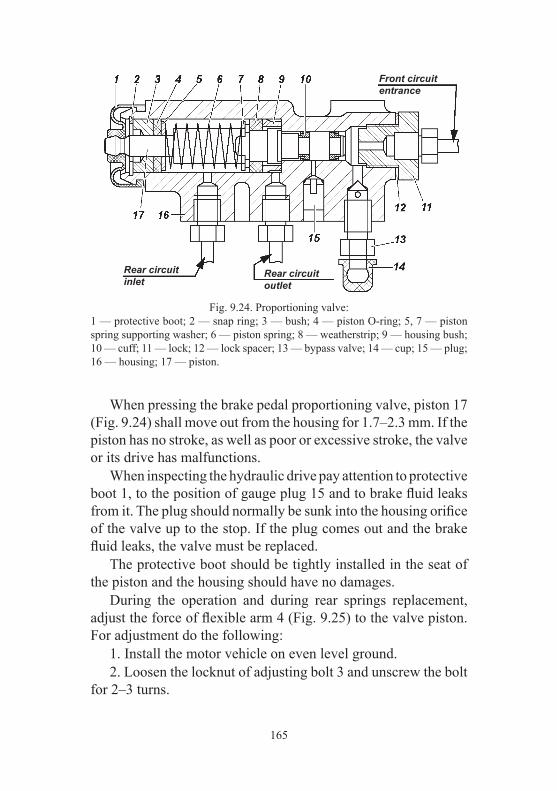
165
When pressing the brake pedal proportioning valve, piston 17 (Fig. 9.24) shall move out from the housing for 1.7–2.3 mm. If the piston has no stroke, as well as poor or excessive stroke, the valve or its drive has malfunctions. When inspecting the hydraulic drive pay attention to protective boot 1, to the position of gauge plug 15 and to brake fluid leaks from it. The plug should normally be sunk into the housing orifice of the valve up to the stop. If the plug comes out and the brake fluid leaks, the valve must be replaced. The protective boot should be tightly installed in the seat of the piston and the housing should have no damages. During the operation and during rear springs replacement, adjust the force of flexible arm 4 (Fig. 9.25) to the valve piston. For adjustment do the following: 1. Install the motor vehicle on even level ground. 2. Loosen the locknut of adjusting bolt 3 and unscrew the bolt for 2–3 turns.
Fig. 9.24. Proportioning valve:1 — protective boot; 2 — snap ring; 3 — bush; 4 — piston O-ring; 5, 7 — piston spring supporting washer; 6 — piston spring; 8 — weatherstrip; 9 — housing bush; 10 — cuff; 11 — lock; 12 — lock spacer; 13 — bypass valve; 14 — cup; 15 — plug; 16 — housing; 17 — piston.
Front circuit entrance
Rear circuit inlet
Rear circuit outlet

166
3. Screw bolt 3 until it touches piston tail 17 (see Fig. 9.24) of the valve. 4. Tighten bolt 3 (see Fig. 9.25) for 2/3 turns (14 edges of the bolt head). 5. Tighten the locknut. 6. Check the stroke of the valve piston (see above). 7. Check adjustment correctness in motion of the motor vehicle. While going on a straight level road with dry surface, brake the motor vehicle until wheels block. If the valve is in order and drive adjustment is done correctly, the front wheels should be blocked slightly earlier than the rear ones. If the rear wheels are blocked earlier, unscrew bolt 3 for 1-2 edges of the bolt head and check the brakes in motion again. Change the fluid regularly for proper work of the brakes: drain old fluid via the bypass valves of wheel cylinders and proportion-ing valve, and then replace it with a new one. Fill the brake system as follows: WARNING! Filling the brake system of ABS-equipped motor vehicles is necessarily carried out at a service station as it requires additional diagnostic equipment. 1. Check all couplings of the brakes hydraulic drive for leak-ages and the flexible rubber pipes and hoses. 2. Clean the bypass valves and the safety caps of wheel cylin-ders, crankcases and proportioning valve from dust and dirt.
Fig. 9.25. Proportioning valve drive:1 — proportioning valve; 2 — drive lever; 3 — adjusting bolt; 4 — flexible arm; 5 — arm pillar.
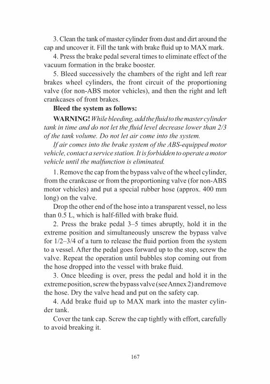
167
3. Clean the tank of master cylinder from dust and dirt around the cap and uncover it. Fill the tank with brake fluid up to MAX mark. 4. Press the brake pedal several times to eliminate effect of the vacuum formation in the brake booster. 5. Bleed successively the chambers of the right and left rear brakes wheel cylinders, the front circuit of the proportioning valve (for non-ABS motor vehicles), and then the right and left crankcases of front brakes. Bleed the system as follows: WARNING! While bleeding, add the fluid to the master cylinder tank in time and do not let the fluid level decrease lower than 2/3 of the tank volume. Do not let air come into the system. If air comes into the brake system of the ABS-equipped motor vehicle, contact a service station. It is forbidden to operate a motor vehicle until the malfunction is eliminated. 1. Remove the cap from the bypass valve of the wheel cylinder, from the crankcase or from the proportioning valve (for non-ABS motor vehicles) and put a special rubber hose (approx. 400 mm long) on the valve. Drop the other end of the hose into a transparent vessel, no less than 0.5 L, which is half-filled with brake fluid. 2. Press the brake pedal 3–5 times abruptly, hold it in the extreme position and simultaneously unscrew the bypass valve for 1/2–3/4 of a turn to release the fluid portion from the system to a vessel. After the pedal goes forward up to the stop, screw the valve. Repeat the operation until bubbles stop coming out from the hose dropped into the vessel with brake fluid. 3. Once bleeding is over, press the pedal and hold it in the extreme position, screw the bypass valve (see Annex 2) and remove the hose. Dry the valve head and put on the safety cap. 4. Add brake fluid up to MAX mark into the master cylin-der tank. Cover the tank cap. Screw the cap tightly with effort, carefully to avoid breaking it.
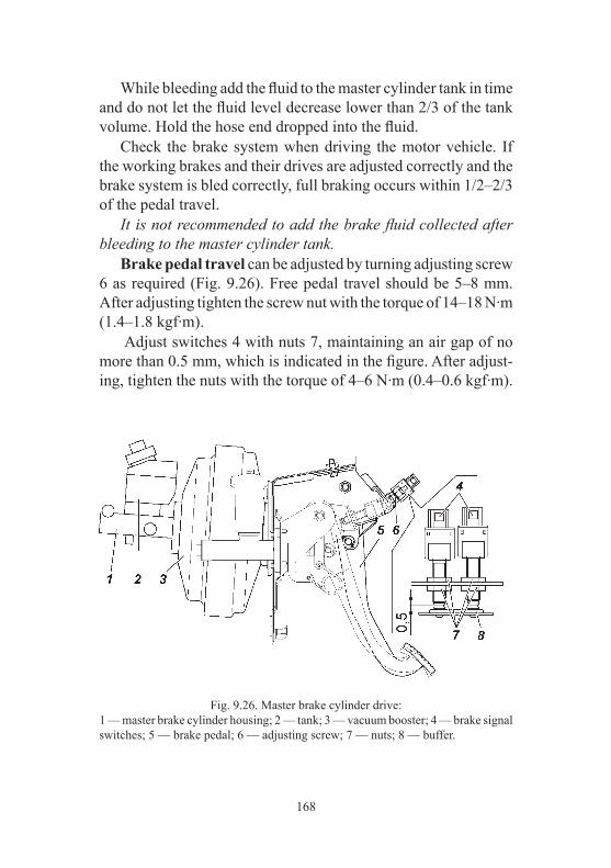
168
While bleeding add the fluid to the master cylinder tank in time and do not let the fluid level decrease lower than 2/3 of the tank volume. Hold the hose end dropped into the fluid. Check the brake system when driving the motor vehicle. If the working brakes and their drives are adjusted correctly and the brake system is bled correctly, full braking occurs within 1/2–2/3 of the pedal travel. It is not recommended to add the brake fluid collected after bleeding to the master cylinder tank. Brake pedal travel can be adjusted by turning adjusting screw 6 as required (Fig. 9.26). Free pedal travel should be 5–8 mm. After adjusting tighten the screw nut with the torque of 14–18 N∙m (1.4–1.8 kgf∙m). Adjust switches 4 with nuts 7, maintaining an air gap of no more than 0.5 mm, which is indicated in the figure. After adjust-ing, tighten the nuts with the torque of 4–6 N∙m (0.4–0.6 kgf∙m).
Fig. 9.26. Master brake cylinder drive:1 — master brake cylinder housing; 2 — tank; 3 — vacuum booster; 4 — brake signal switches; 5 — brake pedal; 6 — adjusting screw; 7 — nuts; 8 — buffer.

169
Parking brake system Wheel parking brake, affecting the brake shoes of rear wheels (Fig. 9.27). WARNING! After the motor vehicle stops, apply the parking brake. When parking the motor vehicle during cold seasons do not apply the parking brake after driving on a wet road, thereby pre-venting the shoes from freezing to the drums. Instead, shift into the first or the reverse gear (any position of the transfer case lever, except for neutral position) and put wheel wedges as required. The wheel parking brake is equipped with the system, which compensates wear of the friction linings automatically, and should not be adjusted during the motor vehicle operation. However, to ensure normal operation of the brake, check the drive cables and adjust them to compensate their tightening and loosening during operation. Adjust the parking brake drive, when the travel of the brake lever is more than 6 clicks of the lever pawl and braking effect is insufficient. WARNING! Use a pit or a hoist for adjustment. Adjust the parking brake drive as follows: 1. Check the air gaps correctness between the brake shoes and the rear brakes drums: press hard the brake pedal several times while the parking brake drive lever is lowered to its extreme position. 2. Lift the rear part of the motor vehicle and put secure struts under it. 3. Set the parking brake lever 3 in the lower position (Fig. 9.27). 4. Compress the drive by tightening the lever with a force of min. 400 N (40 kgf) 2–3 times. 5. Turn nuts 4 and 6 and choose the slack of cables 1, 7, 8. Keep the following sizes: G =1 mm (min), D =35 mm (min), and keep the difference of sizes M and N max. 6 mm (Fig. 9.36). While choosing the slack of cables do not move levers 9.

170
Fig.
9.2
7. P
arki
ng b
rake
driv
e:1
— fr
ont c
able
; 2 —
par
king
bra
ke si
gnal
switc
h; 3
— d
rive
leve
r with
sect
or; 4
, 6 —
nut
s;
5 —
cab
les e
qual
izer
; 7 —
rear
left
cabl
e; 8
— re
ar ri
ght c
able
; 9 —
idle
r lev
er u
nit.

171
6. When adjusted correctly, the lever travel should correspond to 4–6 clicks of the pawl, and when controlling the travel the force to the lever must equal to 600+10N (60+10 kgf). After adjusting lever 3 must be lowered and lifted rear wheels should be turned with hands. It is forbidden to check the parking brake system while moving. It should be done only on a slope. Drive-line parking brake, affecting the driving system (Fig. 9.28). Clean the brake shoes from dust and dirt and sand them, if they get greasy. Replace greasy linings or keep them in clean gasoline for 20–30 min and grind them with sand paper or wire brush. Replace the linings in case of their excessive wear (the rivets are sunk less than 0.5 mm).If the linings are glued, replace worn brake shoes, if the linings wear to a thickness of less than 1.5 mm.Grind the linings on new shoes so that their diameter is 0.3–0.4 mm less than the brake drum diameter. Despite labyrinth seal of the release and adjusting mecha-nisms, they gradually collect dirt, therefore dismantle and clean the mechanisms (especially the release mechanism), adding new grease (Litol-24). Do not let the grease contact the drum and the linings. Adjust the brake when the brake lever travel gets more than half of its maximum travel and when braking effect is insufficient. WARNING! Use a pit or a hoist for adjustment. Adjust the air gaps between the shoes and the drums as follows: 1. Shift the transfer case lever into neutral position. 2. Lower parking brake lever 1 (Fig. 9.28) into its extreme position.

172
Fig.
9.2
8. D
rive-
line
park
ing
brak
e dr
ive:
1 —
driv
e le
ver w
ith se
ctor
; 2 —
stud
; 3, 1
3 —
snap
pin
; 4 —
par
king
bra
ke si
gnal
switc
h; 5
, 6 —
nut
s; 7
— d
rive
cabl
e; 8
— b
olts
; 9 —
sprin
g w
ashe
rs; 1
0 —
adj
ustin
g sc
rew
; 11
— re
leas
e sp
ring;
12
— sp
ring
brac
ket;
14 —
idle
r lev
er; 1
5 —
driv
e ro
d; 1
6 —
lock
nut;
17 —
adj
ustin
g yo
ke; 1
8 —
driv
e le
ver;
19 —
hou
sing
of r
elea
se m
echa
nism
bal
ls.

173
3. Lift the motor vehicle with a hoist. When inspecting the motor vehicle from a pit, do the following: – put wedges under the front wheels; – lift the motor vehicle with a jack from any side of the rear wheels, and put a special stand under the axle shaft housing. 4. Tighten adjusting screw 10 so that the brake drum cannot be turned by hands. 5. As required, choose the slack of cable 7 and drive air gaps by turning nuts 5. As required, adjust the tension of drive cable 7 by changing the length of rod 15 or by moving the drive cable end into the upper position on lever 1. 6. Loosen adjusting screw 10 by 4–6 clicks, so that the drum revolves freely by hands. If adjusted correctly, the travel of lever 1 should correspond to 3–5 clicks of the lever pawl. Adjust the length of the drive-line brake drive rod as follows: 1. Loosen adjusting screw 10 by 4–6 clicks (1/3–1/2 of the torque), so that the drum revolves freely by hands. 2. Unscrew locknut 16 of adjusting yoke 17, remove the snap pin and take out the stud, which connects the yoke with drive lever 18. 3. Match the orifices in the yoke and lever 18 by rotating yoke 17. Choose air gaps in the release mechanism and in the drive by moving lever end 18 with a orifice and rod 15 to each other. 4. Install the stud, cotter it and tighten the locknut. If adjusted correctly, the motor vehicle should brake when the lever pawl is installed into the 4th-6th sector slot from the bottom (4–6 clicks). It is forbidden to check the parking brake system while moving. It should be done only on a slope.

174
ELECTRIC EQUIPMENT
Relay and fuse boxes All the discharge and control relays of the motor vehicle elec-tric equipment, as well as the fuses, are installed in relay and fuse boxes in the cabin and engine compartment of the motor vehicle. The cabin relay and fuse box is located under the cap on the instrument panel, left from the steering column (Fig. 9.29). The scheme of relays and fuses is located on the inner side of the box cap.
Fig. 9.29. Relay and fuse box in motor vehicle cabin:K1 — fog lamps switch relay; K2 — high beam switch relay; K3 — additional interior heater relay: K4 — low beam switch relay; K5 — air conditioner compressor relay; K6 — tail gate window and mirrors heater switch relay; K7 — intermittent wiper; K8 — additional (discharge) relay; K9 — windshield heater relay; K10 — windshield heater timer relay; K11 — rear axle differential lock relay; F1–F25 — fuses (see the table).

175
To access the relay and fuse box, it is necessary to: – disengage the two latches 2 (Fig. 9.30) located in the lower part of the box cover from the back side of the box; – unlock five clips 3 located along the perimeter of the cover, one by one, applying effort in a horizontal plane (in the opposite direction to the movement of the car); – remove the cover carefully without excessive effort. The relay and fuse box under the hood is located on the left, behind the battery (Fig. 9.31). The scheme of relays and fuses is shown on the inner side of the box cap. To access the relay and fuse box, remove its cap. Before replacing a bad fuse, find out the reason for its blowing and eliminate it. Do not use metallic objects while removing a relay or a fuse. Do not use fuses not required by design (see Table 9.1).
Fig. 9.30. Installation of Relay / Fuse Box cover:1 — relay/fuse box cover; 2 — cover latches; 3 — cover clips.

176
Table 9.1. Fuse protected chains
Designation Current, A Protected chainsRelay and fuse box in cabin
F1 10 ‘Dymos’ transfer case 15 AF2 15 Cabin socketF3 10 Air conditioner compressorF4 30 Power options relay box 30 AF5 7.5 Brake signal switch, interior lighting lamps,
glove compartment lamp, luggage compartment lampF6 40 Heating and air conditioning system, tailgate,
and mirror heating switchF7 10 Left fog lightF8 10 Right fog lightF9 20 Windshield wiper switch, windshield wiper,
driver’s switch box, rear-seat passenger switch box, rear bodyshell heater
F10 20 Heating of glass tailgate, mirrors, light control moduleF11 – Not installedF12 20 Cigarette lighter, luggage compartment socketF13 30 ‘Dymos’ transfer case 30 AF14 10 Window lifters (driver door module)F15 5 Cluster 34 A, reverse movement switch, speed sensor 1
A, alarm signal switch 2 AF16 15 AirbagF17 10 Multimedia systemF18 15 Differential lockF19 10 Left high beamF20 10 Right high beamF21 7.5 Left low beamF22 7.5 Right low beamF23 5 Right parking lampF24 5 Left parking lampF25 60 Windshield heatingF26 10 ReserveF27 10 ReserveF28 30 ReserveF29 25 ReserveF30 20 Reserve
Relay and fuse box under the hoodF1 15 HornF2 – Not installedF3 30 Electric fan 2F4 25 ABS (ESP)

177
Fig. 9.31. Relay and fuse box under the hood (without cover):K1 — starter motor relay; K2 — heater relay; K3 — heater relay; K4 — horn relay; K5 — IMECS relay; K6 — electric fan relay; K7 — oil pump relay; K8 — electric fan relay; F1–F10 — fuses (see the table).
Designation Current, A Protected chainsF5 5 InstrumentationF6 20 Oil pumpF7 20 Starter motorF8 30 Elecric fan 1F9 10 Microprocessor-based Engine Control System
(IMECS)F10 10 ABS (ESP)F11 20 HeaterF12 5 HeaterF13 25 HeaterF14 – Not installedF15 – Not installedF16 – Not installedF17 60 Mounting blockF18 40 ABS (ESP)F19 60 Mounting block
End of Table 9.1

178
Alternator WARNING! Even short-time engine operation with the accu-mulator battery off can lead to alternator diodes damage. Turn off the accumulator battery while removing the alternator for maintenance. Keep the alternator clean. To remove dust, blow the ALT off with compressed air.
Accumulator battery WARNING! Use extreme caution when handling electrolyte. Follow these rules to prevent poisoning and chemical burn: – strictly observe the safety requirements specified in the accu-mulator battery manual; – electrolyte or its vapors coming in contact with the mouth, respiratory system, or eyes is extremely dangerous; – avoid any operation that can result in electrolyte getting onto the skin. If this occurs, carefully wipe off electrolyte with cotton wool and immediately rinse remained traces on the skin with 5% solution of ammonia or sodium carbonate; – collect spilled electrolyte with a special filler bulb or an areometer, flush it with water and air the room; – to charge the battery, remove it from the vehicle and unscrew filler plugs; – the battery must be charged in a well-ventilated room. Elec-trolyte fume accumulation is dangerous to health and explosive. Accumulator battery 2 (Fig. 9.20) is installed on a bracket under the hood of the motor vehicle. Check the alternator operation if the accumulator battery is dis-charged, overcharged by the alternator or electrolyte starts boiling. Keep the accumulator battery clean and charged and protect the battery clips and the cable terminals from oxidation. Periodically clean vent orifices in the plug, check electrolyte level and add distilled water as required. Before operation, correct electrolyte density corresponding to the climate area of the motor vehicle operation (see the Battery operating manual).
179
At the factory the motor vehicle is installed with the accumula-tor battery, the density of which is 1.28±0.01 g/cm3. Do not allow continuous battery discharge by a large current (when starting a cold engine in winter time). Thoroughly prepare the engine for starting and turn on the starter motor only for a short period of time — no more than 5 sec. Operate the accumulator battery in correspondence with the Battery Operating Manual, enclosed in the vehicle.
Starter Motor Periodically do the following: – check the bolts that mount the starter motor to the engine for tightening and clean them; – check starter motor terminal ends for cleanliness and mount-ing security Turn off the accumulator battery while removing the starter motor for maintenance. Once the starter motor has been removed: – check the relay switch outputs and the working surface of electric terminals; – check the starter motor drive — a gear, a lever and a spring; – clean the rubbing details from dirt and lubricate them with Litol-24 grease as required. Starter motor drive should move freely with no jamming at the shaft splines, and it should return to the source position by the return spring. The anchor should not revolve when the drive gear goes in the working rotation direction. In case of reverse rotation the gear should revolve with the shaft. Check the ease of rotor rotation in bearings with the brushes lifted by turning the shaft by hands. Warnings: 1. The sleeve of starter motor travel can be broken if the starter motor is on after the engine begins working. 2. Do not wash the starter motor caps and the drive with gaso-line or kerosene to prevent the grease from being removed from the bronze graphite cellular plain bearings.
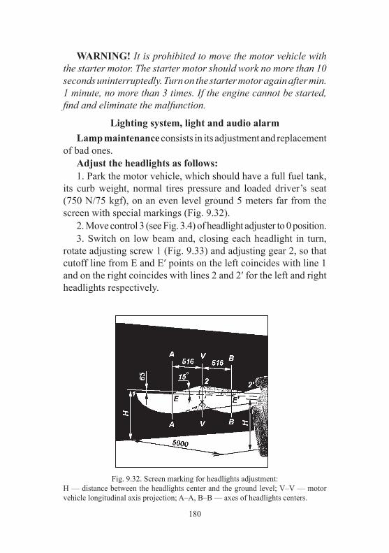
180
Fig. 9.32. Screen marking for headlights adjustment:H — distance between the headlights center and the ground level; V–V — motor vehicle longitudinal axis projection; A–A, B–B — axes of headlights centers.
WARNING! It is prohibited to move the motor vehicle with the starter motor. The starter motor should work no more than 10 seconds uninterruptedly. Turn on the starter motor again after min. 1 minute, no more than 3 times. If the engine cannot be started, find and eliminate the malfunction.
Lighting system, light and audio alarm Lamp maintenance consists in its adjustment and replacement of bad ones. Adjust the headlights as follows: 1. Park the motor vehicle, which should have a full fuel tank, its curb weight, normal tires pressure and loaded driver’s seat (750 N/75 kgf), on an even level ground 5 meters far from the screen with special markings (Fig. 9.32). 2. Move control 3 (see Fig. 3.4) of headlight adjuster to 0 position. 3. Switch on low beam and, closing each headlight in turn, rotate adjusting screw 1 (Fig. 9.33) and adjusting gear 2, so that cutoff line from E and E′ points on the left coincides with line 1 and on the right coincides with lines 2 and 2′ for the left and right headlights respectively.

181
Headlight replacement. To change T/signal lamps remove the connector from socket 6 (Fig. 9.33), turn the socket clockwise (for the right headlight) or counter-clockwise (for the left headlignt) and remove the socket with the bulb. To change the bulbs of high 3 and low 4 beams, remove cap 5. Disconnect the wire from lamps 3 and 4, release the ends of the lamp spring pawl from slots and remove the lamp. Install halogen lamps wearing gloves, do not touch the lamp bulb. If the bulb has fat stains, remove them with alcohol. Front fog lamps. Adjust the front fog lights with screw 1 (Fig. 9.34), using S=5 or Torx T20 keys. Install the light into the position in which the cutoff line coincides with line 1 (Fig. 9.35). To replace front fog lights remove wiring harness connector 2 (Fig. 9.42) from the light, turn it counter-clockwise and remove it.
Fig. 9.33. Headlamp:1 — adjusting screw; 2 — adjusting gear with inner hexagon; 3 — high beam lamp; 4 — low beam lamp; 5 — cap; 6 — T/signal lamp socket.

182
Install halogen lamps wearing gloves, do not touch the lamp bulb. If the bulb has fat stains, remove them with alcohol. Side T/signals are located at UAZ Cargo on front fenders sideways. To change T/signal lamps press catches 1 (Fig. 9.36) and remove T/signals, then take out socket 2 with the lamp. Replace T/signal lamps only when lockers are removed. Side T/Signals are located at UAZ Patriot and UAZ Pickup in rearview mirrors (Fig. 9.37). If the lamps are broken, they are replaced with a new rearview mirror.
Fig. 9.35. Screen marking for front fog lights adjustment:H — distance between the headlights center and the ground level; V–V — motor vehicle longitudinal axis projection; A–A, B–B — axes of headlights centers.
Fig. 9.34. Front fog light:1 — adjusting screw;2 — wiring harness connector.

183
Rear lamps are installed on the rear side of the bodyshell (for UAZ PATRIOT, UAZ PICKUP). Replace tail lamps from the motor vehicle cabin. Remove catch 1 (Fig. 9.38) of lower cap holder 2, pull cap 3 and remove the holder from the upholstery orifice, then turn the cap. You can replace any lamp (Fig. 9.39) by taking out the sockets with lamps by rotating counter-clockwise. Replace the holder and the catch if necessary.
Fig. 9.38. Hatch of tail lamp access:
1 — catch of holder cap; 2 — holder cap; 3 — cap.
Fig. 9.36 Side T/Signal:1 — catches; 2 — socket.
Fig. 9.37. Rearview mirror with side T/Signal

184
License plate lamps are located in the tailgate handle. Untwist screws 7 (Fig. 9.40) and take out the lamp. Insert the screwer to slot 5, press pawl 6, and remove lens 3. Center high mount stop lamp is located at UAZ Patriot on the inside panel of the tail gate (Fig. 9.41). The bad lamp should be replaced. The center high mount stop lamp (Fig. 9.42) is located at UAZ Pickup on the tailgate, depending on configuration and is fixed by catches 1. The bad lamp should be replaced.
Fig. 9.40. License plate lamps:1 — screen of license plate lamps; 2 — lamp housing; 3 — lamp lens; 4 — lamp; 5 — slot; 6 — pawl; 7 — screws.
Fig. 9.39. Tail lamps:1 — socket of brake signal lamp; 2 — socket of T/signals lamp; 3 — socket of reverse lamp; 4 — socket of fog lights and parking lamps.
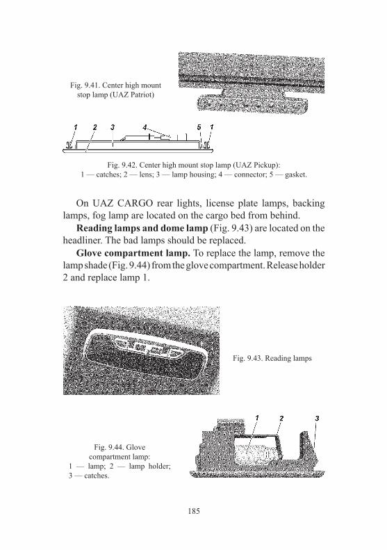
185
On UAZ CARGO rear lights, license plate lamps, backing lamps, fog lamp are located on the cargo bed from behind. Reading lamps and dome lamp (Fig. 9.43) are located on the headliner. The bad lamps should be replaced. Glove compartment lamp. To replace the lamp, remove the lamp shade (Fig. 9.44) from the glove compartment. Release holder 2 and replace lamp 1.
Fig. 9.41. Center high mount stop lamp (UAZ Patriot)
Fig. 9.42. Center high mount stop lamp (UAZ Pickup):1 — catches; 2 — lens; 3 — lamp housing; 4 — connector; 5 — gasket.
Fig. 9.43. Reading lamps
Fig. 9.44. Glove compartment lamp:
1 — lamp; 2 — lamp holder; 3 — catches.
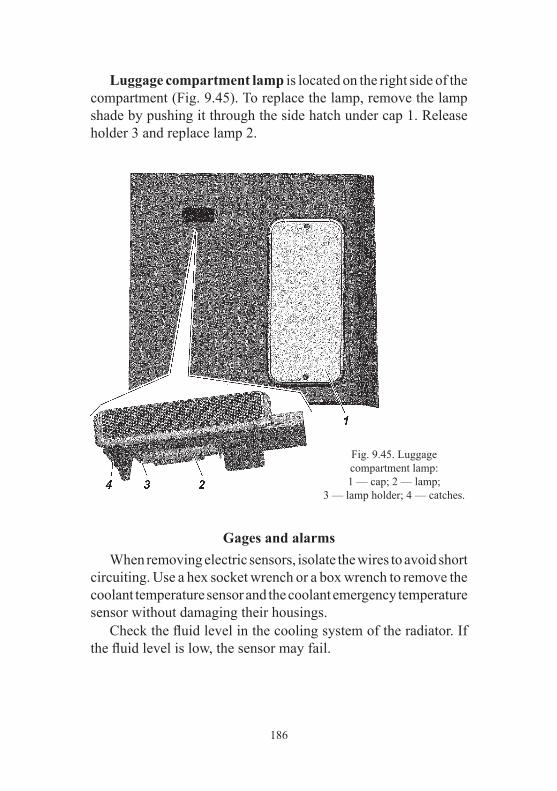
186
Luggage compartment lamp is located on the right side of the compartment (Fig. 9.45). To replace the lamp, remove the lamp shade by pushing it through the side hatch under cap 1. Release holder 3 and replace lamp 2.
Fig. 9.45. Luggage compartment lamp:1 — cap; 2 — lamp;
3 — lamp holder; 4 — catches.
Gages and alarms When removing electric sensors, isolate the wires to avoid short circuiting. Use a hex socket wrench or a box wrench to remove the coolant temperature sensor and the coolant emergency temperature sensor without damaging their housings. Check the fluid level in the cooling system of the radiator. If the fluid level is low, the sensor may fail.

187
Radio equipment+ Loudspeakers are installed on door interior panels, and tweeters are installed on front door interior panels. Multimedia system head unit with 7" display or simplified radio are installed on the dashboard. The monitor of multimedia system can show the picture from rear view camera 4 (Fig. 3.29). Turn the IGN key into position I (Fig. 3.10) to switch on radio or multimedia system. You will find all necessary information about operation and maintenance in the manufacturer’s manual, enclosed in the motor vehicle.
VEHICLE BODY
Always take preventive care of the bodyshell paint to preserve the motor vehicle’s appearance. Do not clean the surface from dust and dirt with dry cloth to avoid scratches. Wash the bodyshell with low-pressure water jet, using car shampoo and a soft cloth. Do not use sponges. When washing the vehicle body using such unit as the “Karcher”, choose regimes “blade”, “fan” or similar. It is not recommended to use the regime “jet” for washing doors and windows to avoid forcing out the rubber seals and ingressing water into the cabin. Wipe dry the washed bodyshell surfaces to avoid stains appear-ing after drying-out in summer, and to avoid cracks appearing after water drops freezing. Do not use soda and alkaline solutions, as it leads to paint fading. WARNING! Do not wash the motor vehicle with the engine started. When possible do not park the motor vehicle under direct sunlight to avoid deteriorating wheel tires and weatherstrips. To take care of the vehicle body coatings, use prophylactic polishing liquids: auto emulsion, polish (spray), wax AB-70 (for vehicles), etc. To restore shine of a faded coated surface of the vehicle body, apply purifying-polishing liquids.

188
During vehicle operation, periodically treat the surfaces (especially closed hollows) with anti-corrosion products, such as ‘Movil’, ‘Tectil’, ‘Nova’ etc, to preserve the bodyshell from pre-mature deterioration. Treat the closed bodyshell hollows through the orifices in floor panels and cross members, which are closed by rubber plugs. As required, recover the bodyshell floor pan, coated with bituminous mastic, by spreading the mastic with a special spray or with a brush.
LUBRICATION OF THE VEHICLE
Long and failure-free motor vehicle work mainly depends on the timely change of oil and grease in units and assemblies. It is strongly recommended to follow the instructions of this manual and the lubrication service Manual. The grease names are indicated in the lubricants and fluids table (see Annex 3). It is not permitted to use oils and greases not indicated in the table, and to break greasing intervals. Methods of assembly lubrication and grease change are described in the corresponding manual sections. Within 24 hours after fording, check oil in all units. If water is detected in the oil, change the oil in this unit and grease all the lubrication nipples of the chassis until the fresh grease squeezes out. While greasing, follow these rules: 1. Drain oil from the engine and the transmission units immedi-ately after the motor vehicle stops while the units are warmed up. 2. Thoroughly remove dirt from the lubrication nipples and plugs before greasing to avoid dirt getting into the motor vehicle mechanisms. 3. Thoroughly remove escaped grease from all the details after lubrication. 4. If the housings of the engine and the transmission units contain excessively dirty oil or the oil contains metal particles, wash the housings before filling fresh oil.

189
5. Mixing (adding) of engine oils of different brands and dif-ferent manufacturers is not allowed. When changing the oil brand or manufacturer, flush the engine lubrication system. 6. Mixing “Litol-24” grease with “Lita” substituting grease is allowed in any proportions. When using other substitutes wash the unit with kerosene. 7. Mixing the brake fluids “Rosa”, “Rosa-3”, “RosDot”, “Tom”, “Rosa Dot-4” is allowed in any proportions.
CHAPTER 10. SPECIAL TOOLS AND APPLIANCES
Each new vehicle, delivered from the manufacturing plant, is equipped with a set of tools and appliances according to the list applicable to the vehicle. A jack (Fig. 10.1 or 10.2) is applied for lifting vehicle wheels when servicing or repairing. Carrying capacity of the jack in Fig. 10.1 is 2 tons, that of the jack in Fig. 10.2 is 1 ton. The highest lifting point of the jack in Fig. 10.1 is 410 mm, that of the jack in Fig. 10.2 is 380 mm. WARNING! If defective or installed improperly, the jack can cause injuries or motor vehicle damage. It is strictly forbidden to carry out any work with the motor vehicle if it stands only on the jack. For jacking up the wheel with jack shown on Fig. 10.1, proceed as follows: 1. Brake the vehicle with the parking brake, shift into the first or reverse gear of the gearbox, making sure that the transfer case gear lever is not in the neutral position. As required, put wedges under the wheel, which is opposite to the jacked up wheel. 2. Install the jack on a level ground under the axle shaft sleeve. 3. Untwist internal jack screw 3 as high as the clearance between the axle shaft housing and the ground allows.
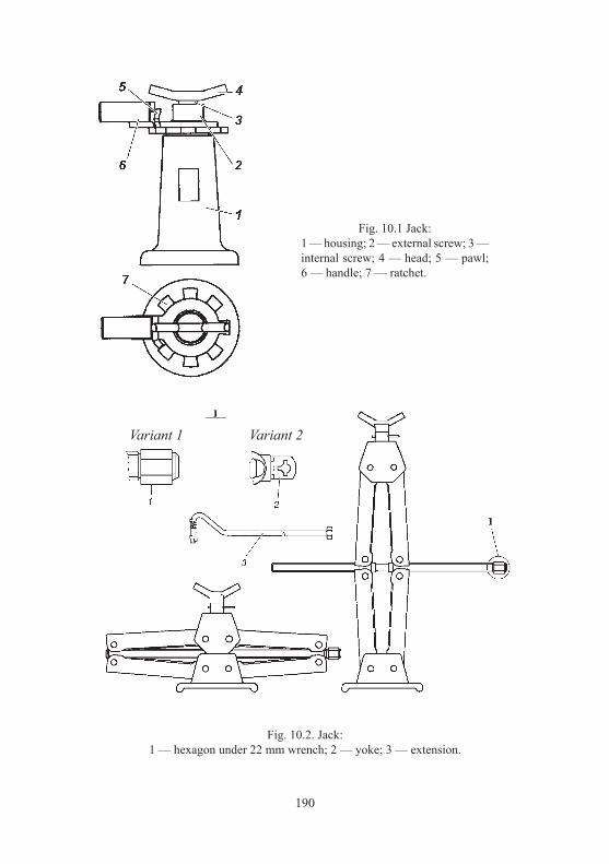
190
Fig. 10.1 Jack:1 — housing; 2 — external screw; 3 — internal screw; 4 — head; 5 — pawl; 6 — handle; 7 — ratchet.
Fig. 10.2. Jack:1 — hexagon under 22 mm wrench; 2 — yoke; 3 — extension.
Variant 1 Variant 2

191
4. Throw latch 5 over the jack to the left-hand side, relative to the jack handle 6, so that latch projection enters the tooth space of the ratchet wheel 7. 5. Lift the motor vehicle to required height by swinging the wheel nut wrench inserted into the handle orifice. 6. To lower the wheels, move the jack “pawl” to the right and deepen the jack screws into housing 1 by swingings the wheel nut wrench. At the end of work, twist external screw 2 and internal screw 3 into the housing up to the stop. To lift the wheels with the rhombus jack in Fig. 10.2, do the following: 1. Brake the vehicle with the parking brake, shift into the first or reverse gear of the gearbox, making sure that the transfer case gear lever is not in the neutral position. As required, put wedges under the wheel, which is opposite to the jacked up wheel. 2. Install the jack on a level ground under the axle shaft sleeve. 3. Lift the motor vehicle wheel to the necessary height by rotat-ing hexagon 1 or yoke 2 clockwise with the “22” mm nut wrench or with extension 3. 4. To lower the wheel, rotate hexagon 1 counter-clockwise with the wheel wrench. At the end of work, fold the jack completely by rotating the hexagon with the wrench. Maintenance of jacks amounts to periodically cleaning it of mud and lubricating its threaded parts. Inspect the riveted couplings, screws and levers of jacks. Screws and levers deformation or damage, as well as riveted couplings loosening are not allowed. If present, replace the jack.
CHAPTER 11. PRESERVATION If the motor vehicle is not operated for a long time (over 3 months), preserve it as follows: 1. Carry out scheduled maintenance. 2. Wash the motor vehicle and dry it. Remove corrosion and paint the areas of damaged paint.

192
3. Fill each engine cylinder with 30–50 g of hot dehydrated motor oil to prevent them from corroding. When spark plugs are screwed off and power wires are disconnected from the ignition coils, turn the engine crankshaft with the starter motor (for 3–5 sec) to spread oil over the entire surface of cylinders. 4. Clean the electric wiring from dirt and dry it thoroughly. 5. Clean all the unpainted exterior metal motor vehicle surfaces and unpainted parts of joint couplings (door hinges, door locks and other units, spark plugs), and grease them with PVK plastic lubricant (or petroleum jelly). Wash the painted parts and dry them. 6. Lubricate the springs with a graphite lubricant. 7. Check and clean the tools and the appliances, wrap them in oiled paper. 8. Seal the windows from outside with light-tight paper (cloth) or shut with shields. 9. Remove the wheels and dismantle them as required. Clean the wheel disks from dirt and corrosion, straighten and paint them. Clean the tires from dirt, wash and dry them. Talc the tubes and the inner side of tires. Collect the wheels and tires, put the normal pressure in them and install on the motor vehicle. 10. As required, flush out the fuel tanks and fill them with fuel. 11. Prepare the accumulator battery for long preservation, fol-lowing the instructions (see accumulator battery operating Manual). 12. Cover the air filter inlet tube and the muffler tailpipe with solid-oiled paper. 13. Loosen the tension of ventilator and alternator drive belts. 14. Drain the fluid from the cooling system and from the wind-shield washer. 15. Seal the housings of the transfer case, front and rear axles by wrapping their safety valves in insulating tape. 16. Cover the gap between the brake shields and the drums with solid-oiled paper. 17. Keep the tires and other rubber details from direct sunlight. 18. Put metal or wooden props under the axles so that the wheels are raised above the floor or the ground.
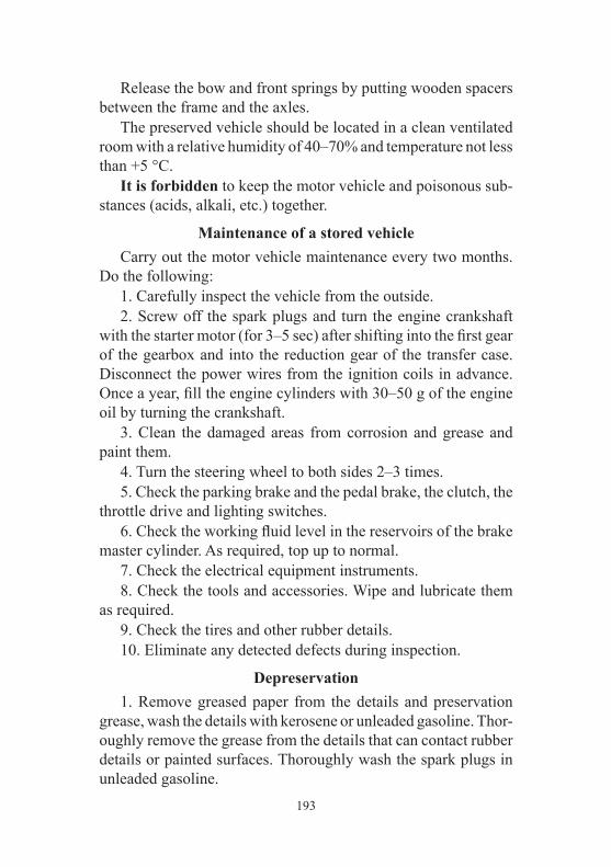
193
Release the bow and front springs by putting wooden spacers between the frame and the axles. The preserved vehicle should be located in a clean ventilated room with a relative humidity of 40–70% and temperature not less than +5 °C. It is forbidden to keep the motor vehicle and poisonous sub-stances (acids, alkali, etc.) together.
Maintenance of a stored vehicle Carry out the motor vehicle maintenance every two months. Do the following: 1. Carefully inspect the vehicle from the outside. 2. Screw off the spark plugs and turn the engine crankshaft with the starter motor (for 3–5 sec) after shifting into the first gear of the gearbox and into the reduction gear of the transfer case. Disconnect the power wires from the ignition coils in advance. Once a year, fill the engine cylinders with 30–50 g of the engine oil by turning the crankshaft. 3. Clean the damaged areas from corrosion and grease and paint them. 4. Turn the steering wheel to both sides 2–3 times. 5. Check the parking brake and the pedal brake, the clutch, the throttle drive and lighting switches. 6. Check the working fluid level in the reservoirs of the brake master cylinder. As required, top up to normal. 7. Check the electrical equipment instruments. 8. Check the tools and accessories. Wipe and lubricate them as required. 9. Check the tires and other rubber details. 10. Eliminate any detected defects during inspection.
Depreservation 1. Remove greased paper from the details and preservation grease, wash the details with kerosene or unleaded gasoline. Thor-oughly remove the grease from the details that can contact rubber details or painted surfaces. Thoroughly wash the spark plugs in unleaded gasoline.

194
2. Fill the engine cooling system. 3. Carry out everyday vehicle maintenance. 4. Check oil level in the engine housing. Drain excessive oil. 5. Before starting the engine fill each cylinder with 30–50 g of the motor oil and turn the crankshaft for 10–15 torques.
CHAPTER 12. TRANSPORTATION Motor vehicles can be transported by railway, water or air transport. When transporting motor vehicles by water or air transport, fasten them in accordance with the water transport shipment scheme or air transport shipment scheme. Use appliances that will not damage the details and the paint of the motor vehicle. The loading and unloading of the vehicles should be carried out by a crane with special grips. During all transport, motor vehicles should be arranged with the following distances between them: 50–100 mm from the side of the engine cooling radiator, 100 mm from all the other sides. The motor vehicle parking brake is on, the engine is off, the lever of the gearbox is shifted into the first gear, the accumulator battery is disconnected. Before transporting by air, the fuel tanks should be filled with fuel to not more than 75% of their capacity. Enter the aircraft in the first gear of the gearbox and in the reduction gear of the transfer case or in the reverse gear.
CHAPTER 13. SCRAPPING The vehicle is scrapped in accordance with local regulations, rules and methods.
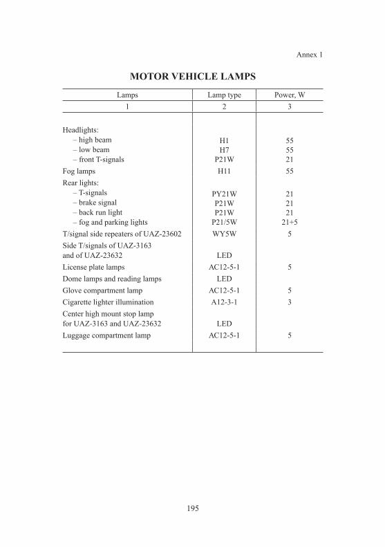
195
Annex 1
MOTOR VEHICLE LAMPS
Lamps Lamp type Power, W1 2 3
Headlights:– high beam– low beam– front T-signals
H1H7
P21W
555521
Fog lamps H11 55Rear lights:
– T-signals– brake signal– back run light– fog and parking lights
PY21WP21WP21W
P21/5W
212121
21+5T/signal side repeaters of UAZ-23602 WY5W 5Side T/signals of UAZ-3163 and of UAZ-23632 LEDLicense plate lamps АС12-5-1 5Dome lamps and reading lamps LEDGlove compartment lamp АС12-5-1 5Cigarette lighter illumination А12-3-1 3Center high mount stop lamp for UAZ-3163 and UAZ-23632 LEDLuggage compartment lamp АС12-5-1 5

196
Annex 2
TIGHTENING TORQUE OF MAIN THREADED COUPLINGS, KGF•M
Engine and its systems:Bolts of crankcase cylinder head (ZMZ-40906 engine):
pretension 3.3–3.7holding min. 1 minutefinal tension — turn to angle 950
Valve cap bolts 0.5–0.7Chain cap screws 2.0–2.5Bolts of front cylinder head cap 1.2–1.8Crankshaft coupling bolt 17.0–20.0Attachment of ventilator drive sleeve to hub 5.0–6.0М16 bolt of engine front strut to engine bracket 9.0–11.0Bolts for fastening brackets of front engine supports to the cylinder block 2.8–3.6Nuts of engine front struts to frame brackets 5.0–6.2Bolt of engine rear strut to bracket 8.0–10.0Nuts of rear strut to frame cross member 2.8–3.6Inlet pipe nuts 2.9–3.6Exhaust manifold nuts 2.0–2.5Self-locking nuts of neutralizer and engine 4.6–5.1Oil housing bolts 1.2–1.8Spark plugs 2.1–3.1Filling pipe collar 0.25–0.35Clamps of cooling system hoses 0.4–0.45Bolts of cooling system radiator 3.6–3.2Upper pads of cooling system radiator 2.0–2.5Bolts of electric ventilator housing 1.5–1.7Oil radiator nuts and bolts 1.8–1.6Starter motor bolts 4.4–5.6Bolts of cooling system pump pulley 1.4–1.8Cooling system pump bolts 2.0–2.5Inlet manifold nuts 2.0–2.5Alternator nuts 2.0–2.5Thermostat housing screws 2.0–2.5

197
Fuel tank fastening bolts 2.0–2.8Filling pipe fastening bolts 0.36–0.5
Sensor bolts (timing sensor, phase sensor, absolute pressure sensor and temperature sensor) 0.6–0.9
Cooling system temperature sensor 1.2–1.8Oxygen sensor 3.5Detonation sensor nut 1.5–2.0Throttle screws 0.6–0.9Ignition coil bolts 0.6–0.9Bolts of clutch pressure plate 2.0–2.5Bolts and nuts of gearbox and transfer case 4.0–5.6Nuts and bolts of propeller shaft flanges 4.4–5.6Pin nut 8–10Bolts of axle housing caps 1.1–2.5Bolts of front axle hub flanges and rear axle shafts flanges 6.0–7.0Ball struts bolts 3.6–5.0Steering mechanism bolts 5.5–8.0Tie rods ball studs nuts 5.0–7.0Tie rods locknuts 10.5–13.0M10 bolt of steering system propeller shaft 4.8–5.6Nut of steering system drag link 20–28Front wheels journal bolts 3.6–4.4Bolts of rear brake shields 4.4–5.6Nuts of pipelines, terminals, brake units, bypass valves 1.4–1.9Bypass valves of the clutch release cylinder 1.0–1.4For working cylinder switch with plastic housing 0.5–0.6Bolts of front disc brakes 14–16Bolts of brake system proportioning valve and coupling bolt nut of proportioning valve drive end 1.4–1.8Bolt and locknut of drive flexible lever in brake system proportioning valve, nut of drive lever axle 2.8–3.6Nut of drive lever (in brake system proportioning valve) to axle bracket and nut of end to pillar 0.65–0.8Nut of longitudinal levers and suspension control arm 14–16Spring U-bolts nuts 9–10Nuts of spring axle 16–18
Appendix 2 (continued)

198
Nuts of spring studs 8.5–9.5Wheel nuts 10–12Adjusting nuts and locknuts of wheel hub bearings 3.0–4.0Lamp clusters nuts 0.15–0.25Nuts of Delphi power steering hoses 2.0–3.5Nut of front spring joint 16–18Steering wheel nut 3.2–3.6Screws of external locks and door locks catches 3.0–4.0
Note — Use the following tightening torque for other threaded couplings:M6 — (0.45–1.0) kgf∙m;M8 — (1.4–1.8) kgf∙m;M10 — (3.0–3.5) kgf∙m;M12 — (5.0–6.2) kgf∙m.
Appendix 2 (end)
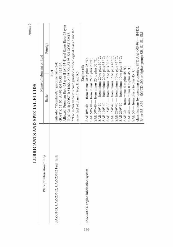
199
Ann
ex 3
LU
BR
ICA
NT
S A
ND
SPE
CIA
L FL
UID
S
Plac
e of
lubr
icat
ion/
fillin
gN
ame
of lu
bric
ant o
r flui
dB
asic
Fore
ign
UA
Z-31
63, U
AZ-
2360
2, U
AZ-
2363
2 Fu
el T
ank
Fuel
unle
aded
“R
egul
ar-9
2” g
asol
ine
(AI-
92-4
) G
OST
R 5
1105
, AI-
92-K
4 G
OST
325
13*,
A
llow
ed: P
rem
ium
Eur
o-95
type
II (A
I-95-
4) a
nd S
uper
Eur
o-98
type
II
(AI-9
8-4)
GO
ST R
518
66, A
I-95-
K4,
AI-9
8-K
4 G
OST
325
13.
**Fo
r mot
or v
ehic
le’s
con
figur
atio
ns o
f eco
logi
cal c
lass
5 u
se th
e sa
me
fuel
of c
lass
5, t
ype
II a
nd K
5
ZMZ-
4090
6 en
gine
lubr
icat
ion
syst
emE
ngin
e oi
lsSA
E 0W
-40
— fr
om m
inus
30
to p
lus 2
5 °C
;SA
E 5W
-30
— fr
om m
inus
25
to p
lus 2
0 °C
;SA
E 5W
-40
— fr
om m
inus
25
to p
lus 3
5 °C
;SA
E 10
W-3
0 —
from
min
us 2
0 to
plu
s 30
°C;
SAE
10W
-40
— fr
om m
inus
20
to p
lus 3
5 °C
;SA
E 15
W-3
0 —
from
min
us 1
5 to
plu
s 30
°C;
SAE
15W
-40
— fr
om m
inus
15
to p
lus 4
5 °C
;SA
E 20
W-4
0 —
from
min
us 1
0 to
plu
s 45
°C;
SAE
20W
-50
— fr
om m
inus
10
to p
lus 4
5 °C
;SA
E 30
— fr
om m
inus
5 to
plu
s 45
°C;
SAE
40 —
from
min
us 0
to p
lus 4
5 °C
;SA
E 50
— fr
om p
lus 5
to p
lus 4
5 °C
;cl
assi
ficat
ions
by
oper
atin
g pr
oper
ties:
STO
AA
I-00
3-98
— B
4/D
2,
B4
or B
5; A
PI —
SG
/CD
, SG
or h
ighe
r gro
ups S
H, S
J, SL
, SM
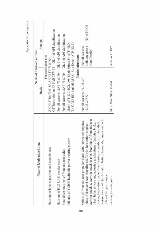
200
App
endi
x 3
(con
tinue
d)
Plac
e of
lubr
icat
ion/
fillin
gN
ame
of lu
bric
ant o
r flui
dB
asic
Fore
ign
Hou
sing
of D
ymos
gea
rbox
and
tran
sfer
cas
eTr
ansm
issi
on o
ilsZI
C G
-F T
op75
W-8
5, Z
IC G
-FF
75W
-85,
GT
Tran
smis
sion
FF
SAE
75W
-85
– G
L-4
of A
PI c
lass
ifica
tion
Hou
sing
of P
AO
UA
Z tra
nsfe
r cas
eFo
r all
seas
ons:
SA
E 75
W/9
0 —
GL-
3 of
API
cla
ssifi
catio
nFi
nal d
rive
hous
ings
of f
ront
and
rear
axl
esFo
r all
seas
ons:
SA
E 75
W/9
0 —
GL-
5 of
API
cla
ssifi
catio
nO
il ta
nk o
f YU
BEI
hyd
raul
ic p
ower
stee
ring
syst
emM
obil
ATF
220,
EZL
998
, She
ll Sp
irax
S4 A
TF H
DX
; ТН
К A
TF II
D; L
ukoi
l ATF
;G-B
ox E
xper
t ATF
DX
III
Plas
tic lu
bric
ants
Splin
es o
f fro
nt a
nd re
ar p
rope
ller s
hafts
with
lubr
icat
ion
nipp
les,
join
ts o
f fro
nt a
nd re
ar p
rope
ller s
hafts
with
lubr
icat
ion
nipp
les,
stee
ring
knuc
kle,
stee
ring
knuc
kles
pin
s, be
arin
gs o
f fro
nt a
nd re
ar
whe
el h
ubs,
rele
ase
and
adju
stin
g m
echa
nism
s of p
arki
ng b
rake
, pa
rkin
g br
ake
driv
e ca
ble,
fron
t bea
ring
of g
earb
ox d
rivin
g sh
aft,
bear
ing
slee
ve o
f clu
tch
shut
off,
batte
ry te
rmin
als,
hing
es a
nd lo
ck
of h
ood,
tailg
ate
hing
es
For a
ll se
ason
s: “
Lito
l-24”
“L
itol-2
4RK
”Fo
r all
seas
ons:
Li
thiu
m g
reas
e —
N3
of N
LGJ
clas
sific
atio
n
Stee
ring
knuc
kle
join
tsSH
RU
S-4;
SH
RU
S-4M
Ret
inax
HD
X2

201
App
endi
x 3
(end
)
Plac
e of
lubr
icat
ion/
fillin
gN
ame
of lu
bric
ant o
r flui
dB
asic
Fore
ign
Hin
ges o
f sid
e do
ors a
nd ta
ilgat
e, d
oor s
tops
, mec
hani
sms f
or fr
ont
seat
s adj
ustm
ent,
mec
hani
sm o
f rea
r sea
t fol
ding
and
fixa
tion,
doo
r lo
cks,
tailg
ate
guid
e pi
n, h
inge
of f
uel t
ank
fille
r cap
TZIA
TIM
-201
Cen
turi
1180
Gui
de b
ushe
s of f
ront
dis
c br
akes
UN
IOL
2M-1
Rub
ber w
eath
erst
rips
Gra
phite
pow
der
Bar
batia
Gre
ase
2Sp
lines
and
join
ts o
f non
-rep
aira
ble
prop
elle
r sha
ftsK
lube
rple
x B
EM 4
1-14
1Fl
uids
Hyd
raul
ic d
rives
of c
lutc
h an
d br
ake
syst
emB
rake
flui
d:
“Ros
Dot
-4”;
“R
osa”
; “R
osa-
3”; “
Tom
”;
For A
BS-
equi
pped
veh
icle
s “R
osa
DO
T-4”
, “R
osa-
3”
SAE
1703
F; D
OT-
4
Engi
ne c
oolin
g sy
stem
Coo
ling
fluid
: O
ZH-4
0 “L
ena”
; O
ZH-6
5 “L
ena”
; TO
SOL
A-4
0M;
TOSO
L A
-65M
; O
ZH-4
0 TO
SOL-
TS
OZH
-65
TOSO
L-TS
Shel
l saf
e
Was
her r
eser
voir
for w
inds
hiel
d an
d re
ar d
oor
“Obz
or”,
Avt
ooch
istit
el st
ekol
-2

202
Annex 4
INFORMATION about precious metals
in motor vehicle electric equipment
Item type Item name Precious metal
Weight, g
6002.3829 Emergency oil pressure sensor silver 0.0310

203
CONTENTSChapter 1. General Information ................................................................................3
Motor vehicle markings .......................................................................................3Specification ........................................................................................................7
Chapter 2. Safety requirements and warnings ........................................................23Safety requirements ...........................................................................................23Warnings ............................................................................................................26
Chapter 3. Control elements, motor vehicle interior and bodyshell equipment ........................................................................................32
Lighting control module ....................................................................................36Instrument cluster ..............................................................................................37Light alarm switch .............................................................................................42Windshield wipersand washers switch ..............................................................43Steering column with steering wheel, and ignition starter switch .....................44Floor box with control units and keys ...............................................................44Motor vehicle electronic anti-theft system with the engine control unit МЕ 17.9.71 ...........................................................51Power options control system ............................................................................56Defensive parking system ..................................................................................65
Rear parking system .....................................................................................65Parking assistance system ............................................................................68
Rear view camera ..............................................................................................70“Autocruise” and “Overspeed limiter” systemElectronic stability program (ESP) ....................................................................78Multimedia system keys unit .............................................................................84Vehicle interior and body equipment .................................................................85
Interior heating, ventilation and conditioning ..............................................85Lighting lamps..............................................................................................95Interior rearview mirror ................................................................................96Exterior rearview mirror ...............................................................................97Sun visors .....................................................................................................97Doors ............................................................................................................98Seats ...........................................................................................................101Seatbelts .....................................................................................................105Airbags .......................................................................................................108Child restraint system installation ..............................................................112Fuel tank plugs ...........................................................................................114Hood ...........................................................................................................115Windshield washers, water pumps .............................................................116Luggage compartment ................................................................................117
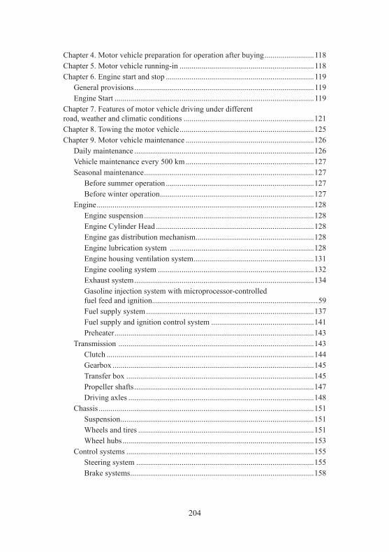
204
Chapter 4. Motor vehicle preparation for operation after buying .........................118Chapter 5. Motor vehicle running-in ....................................................................118Chapter 6. Engine start and stop ...........................................................................119
General provisions ...........................................................................................119Engine Start .....................................................................................................119
Chapter 7. Features of motor vehicle driving under different road, weather and climatic conditions ..................................................................121Chapter 8. Towing the motor vehicle ....................................................................125Chapter 9. Motor vehicle maintenance .................................................................126
Daily maintenance ...........................................................................................126Vehicle maintenance every 500 km .................................................................127Seasonal maintenance ......................................................................................127
Before summer operation ...........................................................................127Before winter operation ..............................................................................127
Engine ..............................................................................................................128Engine suspension ......................................................................................128Engine Cylinder Head ................................................................................128Engine gas distribution mechanism ............................................................128Engine lubrication system .........................................................................128Engine housing ventilation system .............................................................131Engine cooling system ...............................................................................132Exhaust system ...........................................................................................134Gasoline injection system with microprocessor-controlled fuel feed and ignition ....................................................................................59Fuel supply system .....................................................................................137Fuel supply and ignition control system ....................................................141Preheater .....................................................................................................143
Transmission ...................................................................................................143Clutch .........................................................................................................144Gearbox ......................................................................................................145Transfer box ...............................................................................................145Propeller shafts ...........................................................................................147Driving axles ..............................................................................................148
Chassis .............................................................................................................151Suspension ..................................................................................................151Wheels and tires .........................................................................................151Wheel hubs .................................................................................................153
Control systems ...............................................................................................155Steering system ..........................................................................................155Brake systems .............................................................................................158
205
Electric equipment ...........................................................................................174Relay and fuse boxes ..................................................................................174Alternator ...................................................................................................178Battery ........................................................................................................178Starter motor ...............................................................................................179Lighting system, light and audio alarm ......................................................180Instrumentation and warning alarms ..........................................................186Radio equipment ........................................................................................187
Body.................................................................................................................187Lubrication of the vehicle ................................................................................188
Chapter 10. Tools and appliances .........................................................................189Chapter 11. Preservation .......................................................................................191
Maintenance of a stored vehicle ......................................................................193Depreservation .................................................................................................193
Chapter 12. Transportation ....................................................................................194Chapter 13. Recycling ..........................................................................................194Annex 1. Motor vehicle lamps ..............................................................................195Annex 2. Tightening torque of main threaded couplings ......................................186Annex 3. Lubricants and fluids .............................................................................189Annex 4. Information about precious metals in motor vehicle electric equipment ......................................................................193

For Notes

For Notes

UAZ PATRIOT, UAZ PICKUP, UAZ CARGO
Operation manual OM 05808600.132-2011
Seventh Edition
Prepared for publishing by UAZ PJSC Chief Designer Department
Editor-in-chief Chief Designer O. A. KRUPIN
Editor I. L. NIKOLAEV Content by D. A. SHEMYREV
Ulyanovsk Automobile Plant LLCRussia, 432034, Ulyanovsk,92 Moskovskoye Highway
http://www.uaz.ru