Motor Performance Tester
38
Motor Test Bench Ver 6.4 http//www.engineering.co.kr Dynamometer for Motor performance Test Test Bench for Electric Motors and Gearing at Laboratory (R&D), Production (EOL) and Quality Assurance (QA) ENGINEERING KOREA
-
Upload
sangwon-kim -
Category
Documents
-
view
234 -
download
1
description
Motor Performance Tester
Transcript of Motor Performance Tester

Motor Test Bench Ver 6.4
http//www.engineering.co.kr
Dynamometer for
Motor
performance
Test
Test Bench for Electric Motors and Gearing at Laboratory (R&D), Production (EOL) and Quality Assurance (QA)
ENGINEERING
KOREA

Motor Test Bench Ver 6.4
http//www.engineering.co.kr
Test Stand Technology
The ENGINEERING KOREA’s Test Stand can be found in test labs, at inspection stations, and on the manufacturing floors of most of the leading manufacturers, users and certifiers of small to medium sized electric, pneumatic and hydraulic motors, as well as internal combustion engines. ENGINEERING KOREA supplies motor test systems for a wide array of industries including: Appliance, Automotive, Aviation, Computer, HVAC, Lawn and Garden, Medical and Dental, Electric Motor, Office Equipment and Power Tools.

Motor Test Bench Ver 6.4
http//www.engineering.co.kr
The scope of product comprises
motor, engine and other power test
stands with torque-/speed
measurement and manual or external
control, as well as computer controlled
complete solutions for the analysis
and documentation of electrical
machinery.
By means of an integrated power
analyzer, computer controlled test
stands can be realized with current-
/voltage/temperature measurement,
so that a separate efficiency
specification of motor and other drive
systems.

Motor Test Bench Ver 6.4
http//www.engineering.co.kr
Configurations of Motor Dynamometer System
The EHB Series Dynamometer can interface with Motor Test Control System, a wide range of
standard motor output torque, speed, and motor input volt, amp, and watt transducers. The
Motor Test System consists of standard instruments that work independently but can be
networked together, with a Host Computer and other equipment to meet the specific motor
test needs of the user. The dynamometer is modularly designed and constructed to permit easy
adaptation to new loading requirements.

Motor Test Bench Ver 6.4
http//www.engineering.co.kr
Motor Dynamometer System Block Diagram

Motor Test Bench Ver 6.4
http//www.engineering.co.kr
Hysteresis Motor Dynamometer System
M.E.E.TECH's Customized Motor Test Systems allows Windows®-based measurements of the speed and torque characteristics of a wide range of motors, from DC motors, step motor, servo motor to three-phase motors. These hysteresis brake models are PC-based, turnkey
systems custom designed and built to meet your specific motor testing requirements. Users can select from ETB series hysteresis brake components, with ratings from 24 mN·m to 29 N·m. By
adding optional components power supplies, adaptable fixtures, custom tables/cabinets, printers, etc.
ENKR's engineering team can customize PC-based, turnkey systems and modular test benches for
almost any motor test application. NEGINEERING KOREA's motor test equipment with optional modules
allows use for applications environment, vibration, sonic, power analysis including voltage and current measurements and evaluations of high-frequency driver efficiency.
Components • Custom Dynamometer Table with 19 inch rack mounts cabinet with
tilt-out drawer
• EHB Hysteresis Dynamometer (includes blower)
• High-Speed Programmable Dynamometer Controller
• EDyno V3.2 Motor Testing Software
• Single-Phase or Three Phase Power Analyzer
• Adjustable Motor Fixture
• Power Supply (30 VDC, 50 A)
• PC, Keyboard and LCD Monitor with adjustable arm
Application
ENGINEERING KOREA designed this Custom Motor Test System for the testing of motors
performance and endurance and invert, drives.
M.E.E.TECH’s CMTS may contain any of the following:
• One or more Dynamometers
• Programmable Dynamometer Controller
• Power Analyzer
• EDyno Software
• Motor Power Supply (AC and/or DC)
• Computer and Printer
• Interface Cards and Cables
• Custom Test Stand, Table or Cabinet
• Motor Fixturing for Small Motors
• Flexible Couplings
• Multiple Point Temperature Measurement
• Acoustic and vibration measurement
• Cooling System
• On-Site Services: commissioning & technical training

Motor Test Bench Ver 6.4
http//www.engineering.co.kr
Sample Applications
The CMTS can be adapted to several different motor testing applications. Below are a few examples
of the hundreds of applications in which ENKR motor testing equipment is used.
Appliance, Automotive, Aviation, Computer, HVAC, Lawn and Garden, Medical and Dental, Electric
Motor, Office Equipment and Power Tools.
Dynamometer Tables
Features • Easy Mobility: Casters, which incorporate a highgrade nylon wheel with a die-cast aluminum
frame, provide 360° rotation
• Sturdy Construction: Made from extruded aluminum, the dynamometer table is lightweight, strong
and corrosion-resistant
• Leveling Jacks: When at rest and in operation, handoperated
leveling jacks, with rubber pads for vibration control, lift the
casters from the floor to provide a solid foundation
• Versatile: Its industry accepted T-slot extrusions
accommodate standard fractional or metric fasteners allowing
easy reconfiguration
• Blower Mounting: To accommodate blowers required
for brake cooling of certain HD/ED Dynamometers, tables are
drilled and tapped for convenient blower mounting underneath
the table top.
Custom table Options • 19” Rack Mounts: Can be added for dynamometer controllers, readouts, power analyzers and
other supporting electronics
• Table Height: Choose from 2 different working heights to allow testing from either a standing or
seated position
• Locking Drawer: Ideal for a laptop computer
• Built-in Cabinet: For storage of tools and accessories
• Multiple Dynamometers: Up to 3 sets of mounting holes can be drilled and tapped to
accommodate up to 3 dynamometers, depending on the model
• Fixtures and Protective Covers: Can be added to any basic table at an additional cost. Some
assembly required. Adjustable Motor Fixtures are used to locate and hold a motor in place
Motor Test Bench Ver 6.4
http//www.engineering.co.kr
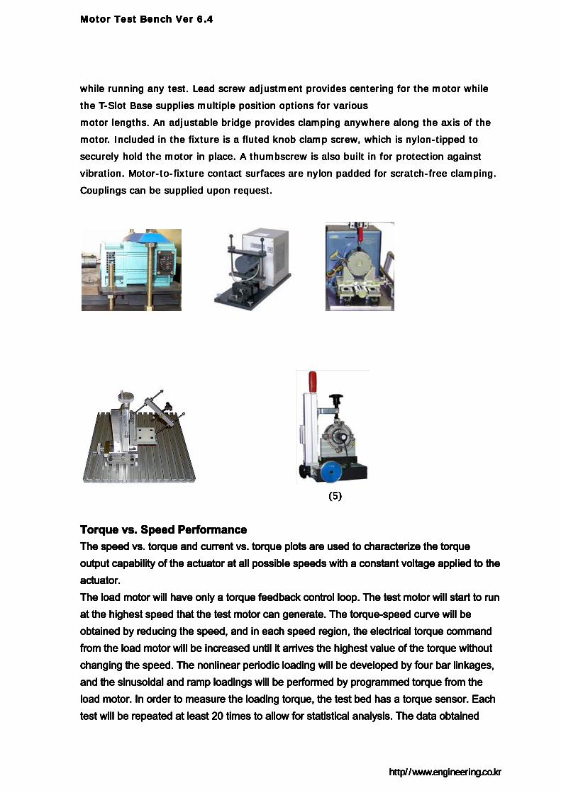
while running any test. Lead screw adjustment provides centering for the motor while
the T-Slot Base supplies multiple position options for various
motor lengths. An adjustable bridge provides clamping anywhere along the axis of the
motor. Included in the fixture is a fluted knob clamp screw, which is nylon-tipped to
securely hold the motor in place. A thumbscrew is also built in for protection against
vibration. Motor-to-fixture contact surfaces are nylon padded for scratch-free clamping.
Couplings can be supplied upon request.
(5)
Torque vs. Speed Performance The speed vs. torque and current vs. torque plots are used to characterize the torque output capability of the actuator at all possible speeds with a constant voltage applied to the actuator. The load motor will have only a torque feedback control loop. The test motor will start to run at the highest speed that the test motor can generate. The torque-speed curve will be obtained by reducing the speed, and in each speed region, the electrical torque command from the load motor will be increased until it arrives the highest value of the torque without changing the speed. The nonlinear periodic loading will be developed by four bar linkages, and the sinusoidal and ramp loadings will be performed by programmed torque from the load motor. In order to measure the loading torque, the test bed has a torque sensor. Each test will be repeated at least 20 times to allow for statistical analysis. The data obtained
Motor Test Bench Ver 6.4
http//www.engineering.co.kr
while running any test. Lead screw adjustment provides centering for the motor while
the T-Slot Base supplies multiple position options for various
motor lengths. An adjustable bridge provides clamping anywhere along the axis of the
motor. Included in the fixture is a fluted knob clamp screw, which is nylon-tipped to
securely hold the motor in place. A thumbscrew is also built in for protection against
vibration. Motor-to-fixture contact surfaces are nylon padded for scratch-free clamping.
Couplings can be supplied upon request.
(5)
Torque vs. Speed Performance The speed vs. torque and current vs. torque plots are used to characterize the torque output capability of the actuator at all possible speeds with a constant voltage applied to the actuator. The load motor will have only a torque feedback control loop. The test motor will start to run at the highest speed that the test motor can generate. The torque-speed curve will be obtained by reducing the speed, and in each speed region, the electrical torque command from the load motor will be increased until it arrives the highest value of the torque without changing the speed. The nonlinear periodic loading will be developed by four bar linkages, and the sinusoidal and ramp loadings will be performed by programmed torque from the load motor. In order to measure the loading torque, the test bed has a torque sensor. Each test will be repeated at least 20 times to allow for statistical analysis. The data obtained

Motor Test Bench Ver 6.4
http//www.engineering.co.kr
from all of the tests will be analyzed by generating the mean and standard error values with the proper assumption of normal distribution. As an initial set of torque-speed curve with respect to several different types of loadings, at least 20 performance maps for this criterion will be obtained. Ten maps are considered with 10 different levels of torque magnitudes in sinusoidal input loadings. Also, 10 additional maps will be obtained from arbitrary generated nonlinear periodic torque loadings in the load motor.
Drag torque calculation of the dynamometer

Motor Test Bench Ver 6.4
http//www.engineering.co.kr
Torque, speed changes at brake load
To get torque vs. speed curves of the industrial actuator, temperature rises according to torque and speed
changes
Temperature rise at brake load
Continuous Stall Torque Temperatures of motor coil, resolver mount, motor housing, and atmosphere are considered in the
testing process as in the torque vs. speed curve. Unlike in the test of the performance curves, in the
continuous stall torque test, it is necessary to find only one data point, the maximum torque
making the actuator stall. The test process is as follows: first fix either speed or brake load at a
constant level. Then command the actuator in current mode increasing the torque or speed
value. If the temperature change of any component reaches steady state, increase the current
command until the temperature of any probe reach is the maximum value of the safe operating
limit.

Motor Test Bench Ver 6.4
http//www.engineering.co.kr
1) Slip or torque ripple testing

Motor Test Bench Ver 6.4
http//www.engineering.co.kr
viscous damping coefficient
torque constant
back EMF constant
mechanical time constant
thermal time constant
torque ripple
velocity variation
ENVIRONMENTAL TEST
Accustic noise Temperature Control Chamber
Hysteresis Absorbing Type
The EHB series hysteresis brake unit applies a uniform braking force according to the electric
current supplied regardless of rotation speed. This compact, easy-to-use high-performance load
applying device is used in our systems for the measurement of motor speed and torque
characteristics.

Motor Test Bench Ver 6.4
http//www.engineering.co.kr
■Main features
• New and improved inner and outer teeth ensure
high-precision control.
• Unit structured to minimize inertial moment.
• Maximum speed: 30,000 rpm.
(Supports wide speed range; low to high rpm.)
(* Maximum speed varies depending on model
and rating.)
• Contact-less brake mechanism offers long
service life.
• Minimum effect from ambient temperature changes.
• Smaller than brake units offered by other companies.
• 14 models available, with rated torques ranging from 5 mNm to 29Nm.
• Products can be tailor-made according to customer need.
Type Torque at
working
current
(Nm)
Working
current
(mA)
Resist
at
25°C
10%
(Ohm)
Volt
(VDC)
max.rpm
25°C
10%
(min )
Possible
dissipation
(Watt)
Residual
torque
without
current
(Nm)
Rotor
inertia
(kgcm )
Weight
(kg) non
cont.
contin
uous
EHB-3 0,024 155 171 25 20000 20 5 3,53x10 0,0043 0,103
EHB-10 0,095 143 180 24 20000 35 8 7,06x10 0,0435 0,238
EHB-20 0,150 232 120 24 20000 50 12 7,77x10 0,0458 0,324
EHB-50 0,380 270 95 24 15000 90 23 1,55x10 0,1670 0,764
EHB-140 1,200 270 95 24 12000 300 75 5,42x10 1,0000 1,850
EHB-250 2,100 289 96 24 10000 450 110 7,77x10 3,4500 3,500
EHB-450 3,600 473 50 24 8000 670 160 1,51x10 7,5000 5,460
EHB-750 5,800 410 60 23 6000 1000 200 5,00x10 14,5000 12,200
EHB-1750 14,500 535 52 26 6000 2400 350 9,18x10 62,5000 24,500
EHB-3500 29,000 1070 26 26 6000 4800 600 1,36x10 125,0000 49,750

Motor Test Bench Ver 6.4
http//www.engineering.co.kr
TORQUE DYNAMOMETERS Angle-torque characteristics measurement Cogging Torque Tester After securing the motor housing in place, this model measures torque per angle byrotating the rotor at 1 r/min, then uploads to a personal computer running Windows® angle-torque characteristics such as low levels of cogging torque for brushless DC motors and detent torque for stepping motors.
■ Primary Advantages
• Enabling high-precision measurements of low torque levels of 0.01 or less. • Employing a vertical structure, realizes measurements with minimized to
eccentricity. • Provides accurate peak-to-peak measurement of cogging torque. • The model offers a wide range of six available measurement heads, with
torque ratings ranging from high-precision measurements. • Motor characteristics are easily ascertained on automatically plotted
performance graphs. • Allows control of measurements and display and storage of data with a
standard personal computer running Windows®.

Motor Test Bench Ver 6.4
http//www.engineering.co.kr
Other Custom Specification Products Dynamometer for Environmental Testers
By connecting the Measuring Unit installed to the Environmental tester (constant-temperature oven) and the shaft of the sample motor placed inside the tester, this Dynamometer measures the rotation speed and torque of an AC/DC motor at certain temperatures and humidity levels (e.g., from -50 to 150 ), displaying the measurement results
on a Windows® PC. When combined with the WT1600 Digital Power Meter, this model accurately measures the input and output of a high-frequency driver.
■ Features The Motor Mounting Jig is not designed to be attached to the base of the Environmental Tester, but directly to the reference board of the Measuring Unit, enabling precise axial alignment with the sample motor for high-accuracy measurements. The Torque Meter Measuring Unit is equipped with our acclaimed TB-type unit (hysteresis brake control and torque detection using tension-bar strain gauge load cell) to ensure stable measurements across a wide spectrum of rotation speeds. ■ Main specifications The product meets the specifications for standard TB-type Torque Meter Measuring Units and Motor Analyzers (control section). It can be used with a range of Environmental Testers offered by various manufacturers. (Some Environmental Testers must be modified to meet specifications.) ■ Basic configuration (illustration depicts an example of a system)
1. PC-EMA1-W2S Motor Analyzer 2. Windows® Personal Computer 3. Torque Meter Measuring Unit (in accordance with motor ratings)

Motor Test Bench Ver 6.4
http//www.engineering.co.kr
4. Motor mounting jig (custom specifications) 5. Environmental Tester (modified) 6. WT-1600 Digital Power Meter (manufactured by
Yokogawa Electric Corp.) 7. Power supply for sample motor
By connecting the Measuring Unit installed to the Environmental tester (constant-temperature oven) and the shaft of the sample motor placed inside the tester, this Dynamometer measures the rotation speed and torque of an AC/DC motor at certain temperatures and humidity levels (e.g., from -50 to 150 ), displaying the measurement results on a Windows® PC. When combined with the Digital Power Meter, this model accurately measures the input and output of a high-frequency driver.
■ Features The Motor Mounting Jig is not designed to be attached to the base of the Environmental Tester, but directly to the reference board of the Measuring Unit, enabling precise axial alignment with the sample motor for high-accuracy measurements. The Torque Meter Measuring Unit is equipped with our acclaimed TB-type unit (hysteresis brake control and torque detection using tension-bar strain gauge load cell) to ensure stable measurements across a wide spectrum of rotation speeds. ■Main specifications The product meets the specifications for standard TB-type Torque Meter Measuring Units and Motor Analyzers (control section). It can be used with a range of Environmental Testers offered by various manufacturers. (Some Environmental Testers must be modified to meet specifications.) ■ Basic configuration (illustration depicts an example of a system)
1. Motor Analyzer Dynamometer 2. Windows® Personal Computer 3. Torque Meter Measuring Unit (in accordance with
motor ratings) 4. Motor mounting jig (custom specifications) 5. Environmental Tester (modified)
Motor Test Bench Ver 6.4
http//www.engineering.co.kr
6. Digital Power Meter (option) 7. Power supply for sample motor
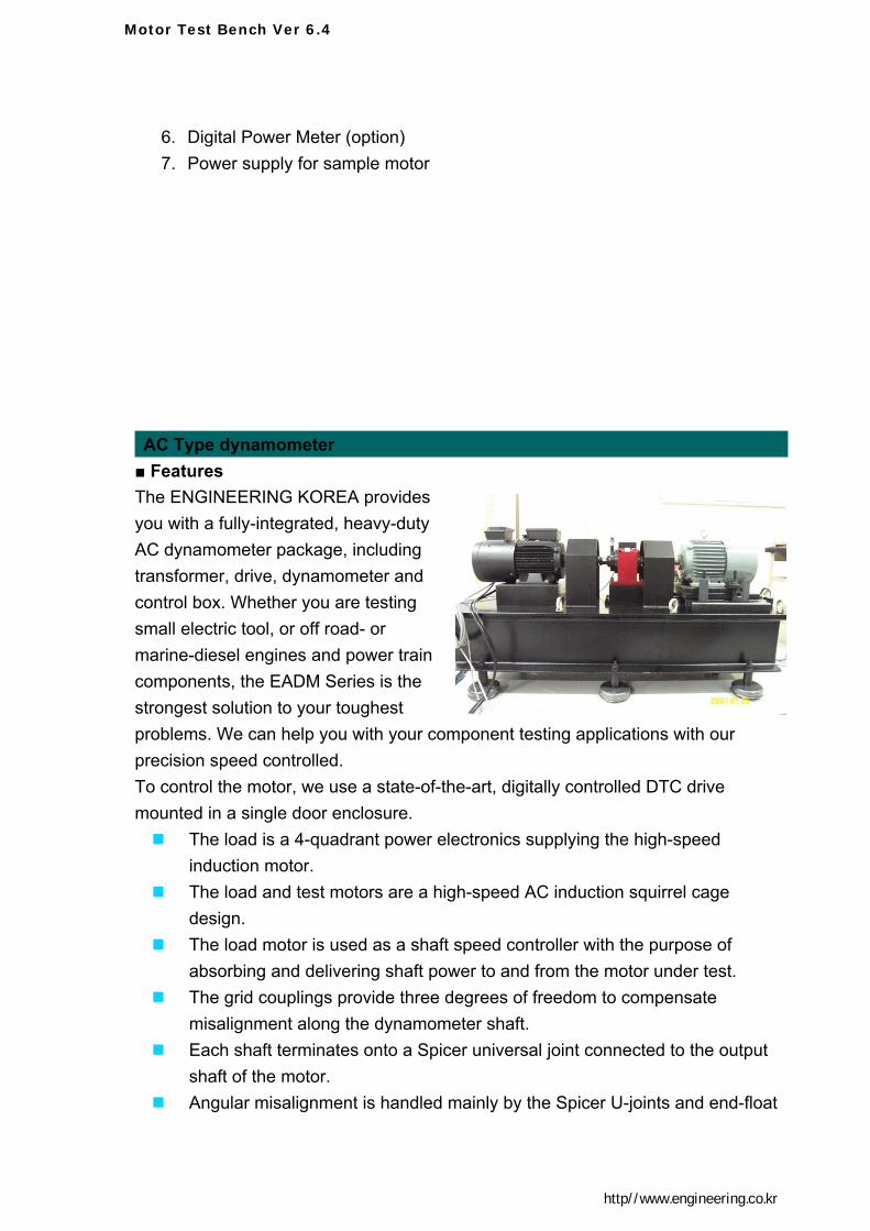
AC Type dynamometer ■ FeaturesThe ENGINEERING KOREA provides you with a fully-integrated, heavy-duty AC dynamometer package, including transformer, drive, dynamometer and control box. Whether you are testing small electric tool, or off road- or marine-diesel engines and power train components, the EADM Series is the strongest solution to your toughest problems. We can help you with your component testing applications with our precision speed controlled. To control the motor, we use a state-of-the-art, digitally controlled DTC drive mounted in a single door enclosure.
The load is a 4-quadrant power electronics supplying the high-speed induction motor.
The load and test motors are a high-speed AC induction squirrel cage design.
The load motor is used as a shaft speed controller with the purpose of absorbing and delivering shaft power to and from the motor under test.
The grid couplings provide three degrees of freedom to compensate misalignment along the dynamometer shaft.
Each shaft terminates onto a Spicer universal joint connected to the output shaft of the motor.
Angular misalignment is handled mainly by the Spicer U-joints and end-float
Motor Test Bench Ver 6.4
http//www.engineering.co.kr
is absorbed within the Falk coupling. In addition to this limitation, which limits the maximum speed of the entire
test-bench The bearings of this component have to be supplied by an external oil-
reservoir. The induction motor itself is supplied by a frequency inverter and control unit. The motor may be operated with field oriented control (FOC) or just by using
a voltage-frequency-characteristic. Cooling (option)
Cooling is accomplished by a closed loop circulating oil bath and a heat exchanger.
The oil circulates, cools, and filters prior to returning to the motor.
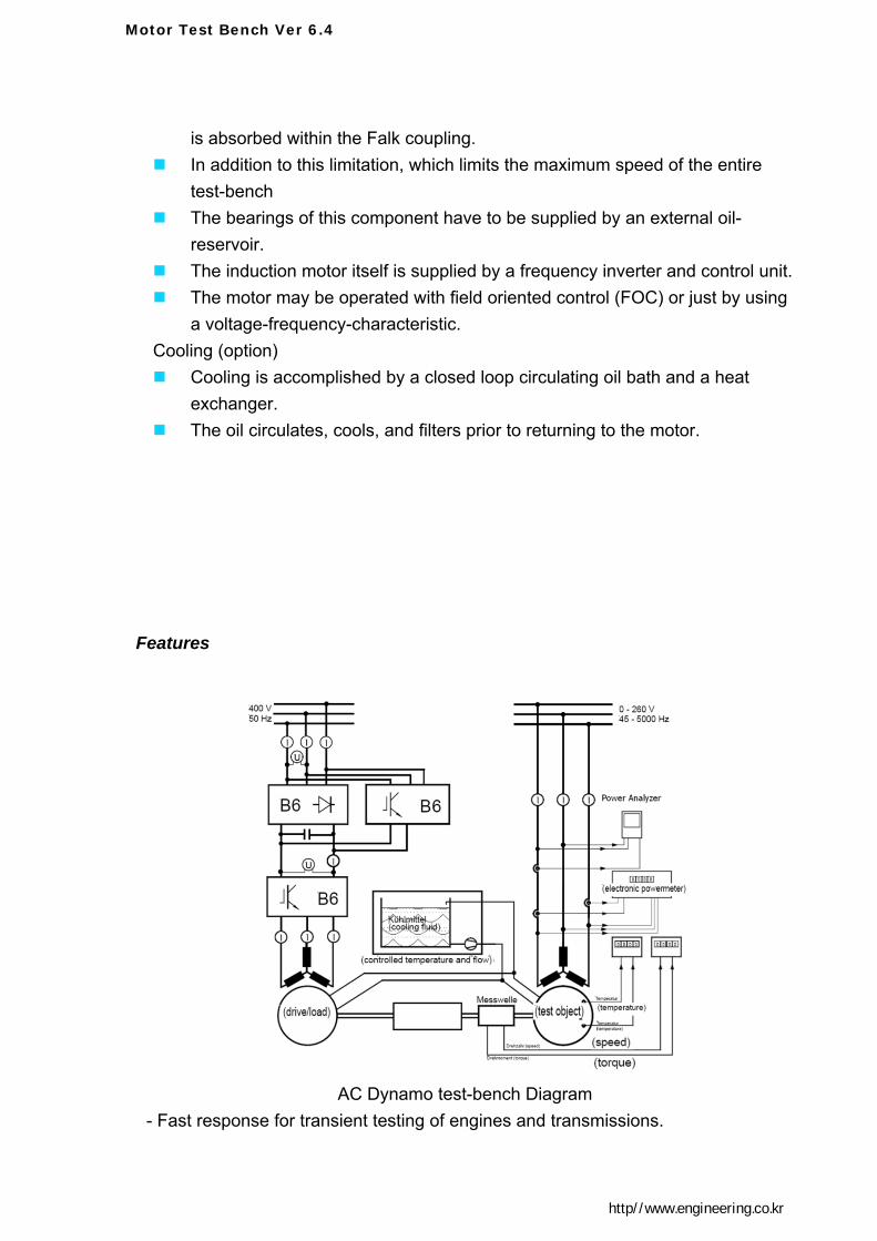
Features
AC Dynamo test-bench Diagram
- Fast response for transient testing of engines and transmissions.

Motor Test Bench Ver 6.4
http//www.engineering.co.kr
- Accurate and repeatable dynamometer control. - Data Acquisition and throttle control available. - Motor mounted encoder for speed regulation of 0.01% - precise control - Drive capable of holding motor at full torque with "0" speed - Test fuel measurement systems, gas analyzers, combustion analysis is systems,
and more The design of the test-bench is composed of a high-speed inverter-driven induction motor as a load and a torquemeter specially designed for this speed level. In addition, a controlled cooling system is applied to guarantee certain operating points during the measurements. AC
Dynamometer Controller
Regulator Type: Digital Modification: Programmable Control: Vector Algorithm Torque Control: Programmed with Speed Limit for Speed Accuracy: 0.04% Closed Loop Torque Accuracy: 0.5% Control Functions: Speed or Torque Analog Inputs: Speed Output & Torque Output Analog Outputs: Start, Stop, E-Stop, FWD-REV, RESET & Mode Selection
Inputs
Controlled cooling(option) The thermal behaviour of electrical drives critically determines the
performance characteristics. The knowledge of the thermal state of the drive is an essential prerequisite for
a detailed analysis (e.g. efficiency measurements).

Motor Test Bench Ver 6.4
http//www.engineering.co.kr
This test-bench is equipped with a means for controlled liquid cooling of the test objects.
Linear Power amplifier
This linear amplifier is used to drive the test motors in addition to an inverter supply.
From a comparison the influence of the inverter supply on the test drive can be measured.
The reference value input realized by setting the system parameters by analogue input (e.g. potentiometer) or by digital input (e.g. keyboard or bus).
The program. The vector control software is identical for PM motor inverter pace vector
modulation Zero voltage transition (ZVT) circuit was installed Uses the same vector control software and tune-up parameters as the
previous inverter drive. Power Connection Cooling Hoses Accessible

Motor Test Bench Ver 6.4
http//www.engineering.co.kr
Eddycurrent Brake type Dynamometer
Eddy current EV Motor Test
Water Brake type Dynamometer ■ Features ENGINEERING KOREA provides you with a fully-integrated, heavy-duty water brake type motor test dynamometer package, from simple speed, torque and power display systems with manual control to completely automated testing solutions, to meet your testing requirements. Our Dynamometer Electric Motor Testing Systems are designed to provide maximum reliability, excellent durability and flawless performance. Using our extensive line of water brake type Dynamometer has systems available for testing electric motors from 5 to 13,000hp. To control the motor, we use a state-of-the-art, digitally controlled DTC drive mounted in a single door enclosure. These affordable Water-Brake Dynamometers are proven durable designs which use water flowing through the absorber to create a load on the motor. Only the amount of water necessary to provide the load is required. It needs cooling water and thermal overload protection, unlike typical industry offerings. If the water overheats under test and vaporizes, then the dynamometer simply stops absorbing the load. With equal absorption in both CW and CCW directions, operator set up is reduced. Precise load control of the dynamometer is as simple as increasing or decreasing water volume flowing through the dynamometer absorption body. With different control options available, torque, RPM, and optionally water temperature are displayed on highly accurate digital instrumentation. It can also customize your system with special water cooling system options, adjustable lift tables, drive shafts with shaft guards, and custom controls and

Motor Test Bench Ver 6.4
http//www.engineering.co.kr
instrumentation. These systems can be set up for simple, manual operation or more sophisticated computer controlled operation. With all of the available options for motor load testing, the ENGINEERING KOREA Water Brake Dynamometer offers the most economical, durable, precise motor loadtesting option available today. Water type Motor Test Dynamo WMT 550 Series The small motor test unit offers
exceptional electric motor load testing capabilities and features an adjustable mounting platform that provides for a wide range of electric motor placement. In addition, a durable water absorber, automatic load control, and an integrated cooling system allow for continuous-duty testing of motors up to 550 HP(410Kw). With the included DPM (Digital Power Meter), the system displays speed, torque, and power. With the DPM, load can be set to allow continuous testing at a constant torque. The included Data Logger software, which can be installed on any PC-based computer, displays torque, HP, RPM, and percent slip in real time and allows test report printout. Electric motor power and torque verification has never been easier, or more affordable. The test stand, complete with casters, allows easy positioning within a test area. Precise load is provided by a water hose hook up and a variable frequency pump supplying metered water to the water absorber. A Motor Test Center for powering up the motor is required to complete the Motor Load Testing package.

Motor Test Bench Ver 6.4
http//www.engineering.co.kr
Features • Adjustable Table with optional Manual Test Motor Lift Table Adjustment • Equal Absorption in Both CW and CCW Directions • Power up to 550Hp(410Kw) • Speed up to 2,550rpm • Water uses: 40GPM(2.5L/s)(no cooling system) • Integrated VFD Water Pump for Precise Metering of Water • Optional Integrated Water Holding Tank for Water Recirculation with
Automatic Temperature Control for Water Supply/Drain • Automatic Load Control with LED Readout • Data Logger Software/Computer Interface Included • Optional Double U-Joint Drive Shaft and Shaft Guard • Optional Shaft Adaptors Available • Crated Dimensions/Weight: 96’L x 48”W x 54”H, 2,000 Lbs. Model WMT 2000

Motor Test Bench Ver 6.4
http//www.engineering.co.kr
WDC-5000 WMT Series Dynamometer Control and measurement System

Motor Test Bench Ver 6.4
http//www.engineering.co.kr
The WDC5000 system is a display only system intended for basic engine and motor dynamometer testing requirements. This system provides for the measurement of torque in either tension or compression (both clockwise and counter-clockwise
engine rotation) and speed from a standard Magnetic Pickup. The system is designed to set on a table or desktop near the PC. collects data for Engine or Motor RPM,,Torque and Power. The system connects to a standard PC using a single USB cable / port. The software is designed for use on a PC running either the Windows XP™ or Windows Vista™ operating system. The PC (purchased separately) may be customer provided or purchased from ENGINEERING KOREA. When a PC is purchased from ENGINEERING KOREA along with the WDC5000 system, the software is pre-installed and tested prior to shipment. This system is NOT upgradeable. Water type Motor Test Dynamo WMT 3000 Series
WMT3000 Series motor test unit offers exceptional electric motor load testing capabilities and features an adjustable mounting platform that provides for electric motor placement. You can select 12 different range of Absorbing module from DX31 to DX3012 as your test motor capability. In addition, a durable water absorber, automatic load control, and an integrated cooling system allow for continuous-duty testing of motors 250 to 3,000 HP.
Features
• Adjustable Table with optional Manual Test Motor Lift Table Adjustment • Equal Absorption in Both CW and CCW Directions • Power range: 250~3000HP(19~2,237Kw) • Speed up to 4,000rpm • Torque range: 13084Nm@1,600rpm • Integrated VFD Water Pump for Precise Metering of Water • Optional Integrated Water Holding Tank for Water Recirculation with
Automatic Temperature Control for Water Supply/Drain • Automatic Load Control with LED Readout

Motor Test Bench Ver 6.4
http//www.engineering.co.kr
• Data Logger Software/Computer Interface Included • Optional Double U-Joint Drive Shaft and Shaft Guard • Optional Shaft Adaptors Available • Crated Dimensions/Weight: 96’L x 48”W x 54”H, 2,000 Lbs.

Motor Test Bench Ver 6.4
http//www.engineering.co.kr
Controller
Edyne figure, using up to four signal conditioning modules, to acquire data from a wide variety of sensors and transducers. For use with SpeedDyne is configured basically with modules to acquire torque, rpm of brake mechanical power, others electric power of motor current, voltage and vibrations, sound, temperature. Two spare slots can be used to acquire data from other sensors, such as accelerometers, encoders, or other sensors with a high- level output. Data is stored and analyzed on a laptop computer.
The data are rated values, generally able to be obtained. On demand, they may be extended or, according to circumstances, supplemented with other parameters.
MDC-5000 series
DPM DISPLAY AND CONTROL UNIT is included with each test stand. Torque is controlled by turning a potentiometer which controls the water

Motor Test Bench Ver 6.4
http//www.engineering.co.kr
flow into the absorber through the VFD pump. The DPM (Digital Power Meter) provides the user with torque, speed displays on the LED metering, measured directly from the absorber. A computer interface and DPM Data Logger software is included, which when connected to a computer, allows data to be displayed, graphed, recorded, and printed. Digital signal conditioner and power controller Powered by the power controller, and digital meter based on a precision instrumentation strain amplifier, the unit amplifies and filters the torque signal. It also provides power and connections for the speed pickup sensor which is located in the dynamometer.
Hysteresis, Eddy current, electromagnetic particle type brake
Load control Torque/RPM Display 19” 2U size
Power control suit for load control • Supply of Programmable DC Power for brake load control. • CV / CC mode operation • Two power modes (+), (-) each variable output provided
• OUTPUT ON/OFF function provided
• Able to store and to recall up to five operation states (Voltage, Current)
• Slim 19 Half x 2U size (less than 300 W)• RS-232C attached by default (RS-485 Option)
Torque, RPM display
• TORQUE & RPM digital display• Resolution24bit ADC, 16bit DAC• Accuracy, stability: (>0.01% F S)• Unit select: kg, N, b, kg/ , bar, MPa• Sample rate: 1000samle/s)• Calibration Actual load and sensor
output • Auto zero Function: Digital and Analog
Interface with PC or PLC

Motor Test Bench Ver 6.4
http//www.engineering.co.kr
Interface with digital power controller, and digital torque/rpm meter by serial(RS-232/485) communication port

Motor Test Bench Ver 6.4
http//www.engineering.co.kr
Dynamometer Control System
M.E.E.TECH’s dynamometer controller provides superior resolution for data acquisition and curve
plotting. This allows for capturing more usable motor test data during switching, breakdown and
other transitional areas of the motor test curve. For production and incoming inspection, it displays
torque, speed and power at all times, allowing the dynamometer controller to be used as a manual
stand-alone unit or as part of a complete PC system. It requires calibration with its associated
dynamometer, it is suggested that the dynamometer and Torque/Speed Conditioner be ordered
together in order for ENGINEERING KOREA to perform this calibration before leaving the factory.
The customer must then perform the (Zero, CW & CCW) calibration on site, as outlined in the
User's Manual.

Motor Test Bench Ver 6.4
http//www.engineering.co.kr
Power Analyzer
Three -Phase General Purpose Power Analyzer The 2553 Power Analyzer incorporates the ideal combination of precision, speed and ease-
of-use in an instrument so economical it can be on every bench.
The six-key front panel has four ‘soft’ keys
whose menus simplify the selection of
measurements. In addition to numerical results,
the 2553 captures waveforms with true 400-point
precision. These wave forms can be displayed or
directly output at full resolution to a PCL printer.
Power and amplitude measurements with an
accuracy of 0.1% are automatically synchronized to the fundamental frequency.
Peak measurements of voltage, current and power include continuous, inrush, and history modes,
plus an accumulation mode for W-Hr, A-Hr, and VA-Hr. The 2551 also provides a glitch mode that
captures and displays waveform with the highest anomaly.
Checks the status of incoming signals and alerts the technician if a probe is not functioning properly or is not properly connected to the correct phase. The technician can then correct the condition and use the graphical and textual feedback from Probe Check to ensure that the test data will be properly acquired. • DC, AC one phase three phase
• Sample rate100 kHz
• Amps, watts, volt-amps, frequency, crest factor, Vpeak, Apeak and power factor

Motor Test Bench Ver 6.4
http//www.engineering.co.kr
Power system configulations
Power Analyzer • NVH, acoustics, and vibration measurement system
• Applications include automotive NVH, beamforming, sound power, and structural monitoring
• Expandable from 4 to 32 accelerometer/microphone channels
• Up to 24 bits resolution and 102 dB dynamic range
• Mixed-measurement modules available
Quality and Reliability Using the latest digital signal processing and circuitry, XiTRON’s sophisticated technology gives
our customers the edge in design verification and product manufacturability.
Measures and displays power, frequency, harmonics, THD, CF, K-Factor, Triplens & Inrush
Up to 1500 volts peak, 40 amps peak internally & up to 10,000amps with the use of External
Current Transducers
DC and 20mHz – 100kHz Frequency Range
Graphics Display shows numerical results, waveforms, bar graphs & history plots
16-bit A-D takes up to 220k samples/second
Simple 6-key user interface
PCL/Text Printer output,IEEE488 interface included
Analog voltage and frequency outputs from the torque computer are connected to the power
analyzer and to the data acquisition unit.
The power analyzer averages and synchronizes the torque and speed signals with the motor
AC power, the resulting motor power and efficiency is made immediately available for steady
state analysis.
The power analyzer used on the dynamometer measures AC, DC, and motor shaft power.
It combines all energy measurements and interfaces to a computer for datalogging.

Motor Test Bench Ver 6.4
http//www.engineering.co.kr
The two-wattmeter method is used to measure AC power between the motor and inverter.
DC link power measurements are timed to occur simultaneously with AC power.
Efficiency of the inverter is immediately calculated and more accurate than if separate
instruments were used
Temperature & Analog Measurement
• 4 thermocouple or ±80 mV, 14 S/s analog inputs
• 24-bit resolution; 50/60 Hz noise rejection
• Compatibility with J, K, R, S, T, N, E, and B thermocouples
• Advanced security with 128-bit AES data encryption and IEEE 802.11i (WPA2) support
• Includes NI-DAQmx measurement services software and LabVIEW SignalExpress LE

Motor Test Bench Ver 6.4
http//www.engineering.co.kr
Software
Motor Analysis & Evaluation Software Motor & Power Quality Analysis The SpeedDyne is LabView based powerful software in demanding industrial environments since 2000.
A major characteristic of Dyron is the use of a very powerful dedicated software packed allowing the operator to quickly develop any kind of complex test or trial program, offering multiple capabilities for data processing, automatic editing of reports from database.
A particular advantage is the possibility to link several tests stands
into a network, each of them having different or same configuration, and all of them able to be monitored by a central control computer. So, some opportunity arises to carry out flexible industrial measurement systems for manufacturers.
Acquiring test data using Endyne is easy, fast, and reliable. Transducer and acquisition system information is stored in the system’s database for quick setup. Simply click on a virtual connectors in Edyne configuration screen, select the transducers that are connected to the system, specify the type of test to be performed, and acquire test data..
System voltage Motor current Motor loading Performance Rotor condition Stator condition Auxiliary alarms (for additional input channels such as accelerometers)

Motor Test Bench Ver 6.4
http//www.engineering.co.kr
Automated Reports Automated reports include the following motor operating parameters:
Speed Slip Output horsepower Output torque Efficiency Percent of rated load
These parameters are important in determining whether the motor is operating within the proper range and whether the load is appropriate for the motor. In addition, the ability to trend motor efficiency for a given load can be an effective means of detecting motor degradation.

Motor Test Bench Ver 6.4
http//www.engineering.co.kr
Analysis Plots Edyne provides customized plot generating features that allow the user to develop X-Y. Several different current probes are available, depending on user requirements. Voltages up to 700 volts (RMS) may be monitored using the supplied probes and attenuator Trend plots, and Histograms using any of the parameters calculated by the system.
Signature Analysis
When more detailed analysis is called for, Edyne signature analysis feature
▲DC motor measurement using torque cont
rols ▲Three-phase AC motor measurement using
rpm controls
▲RPM controls
▲Measurements of pull-in and pull-out torque
for a low-torque stepping motor.
▲
▲Measurements of pull-in and pull-out torque f
or a five-phase stepping motor.

Motor Test Bench Ver 6.4
http//www.engineering.co.kr
▲Measurement of stepping motor detent
torque and holding torque (overlay display)
▲Measurement of torque ripple of DC fan motor
under restraint
▲Temperature of motor measurement using
▲ Signature analysis (frequency domain) These include: Frequency domain analysis (FFT) Filtering Time domain analysis Calculated traces Trace overlay

Motor Test Bench Ver 6.4
http//www.engineering.co.kr
▲ 3phase back EMFs and zero-
crossings of back EMFs
▲ Motor speed and current curve at pump
start point