Motor controller SFC−DC - Festo · Festo P.BE−SFC−DC−CO−EN en 1005b IX Intended use The...
362
Manual Motor controller with fieldbus interface for CANopen Type SFC−DC−VC−...−CO Manual 540 424 en 1005b [736 318] Motor controller SFC−DC
-
Upload
nguyenliem -
Category
Documents
-
view
226 -
download
0
Transcript of Motor controller SFC−DC - Festo · Festo P.BE−SFC−DC−CO−EN en 1005b IX Intended use The...

Manual
Motor controllerwith fieldbusinterface forCANopen
Type SFC−DC−VC−...−CO
Manual540 424en 1005b [736 318]
Motor controllerSFC−DC


Contents and general instructions
IFesto P.BE−SFC−DC−CO−EN en 1005b
Original de. . . . . . . . . . . . . . . . . . . . . . . . . . . . . . . . . . . . . . .
Edition en 1005b. . . . . . . . . . . . . . . . . . . . . . . . . . . . . . . . . .
Designation P.BE−SFC−DC−CO−EN. . . . . . . . . . . . . . . . . . . . . .
Order �no. 540 424. . . . . . . . . . . . . . . . . . . . . . . . . . . . . . . . .
© (Festo AG�&�Co. KG, D�73726 Esslingen, 2010)Internet: �http://www.festo.comE−mail: �[email protected]
The reproduction of this document and disclosure to thirdparties and the utilisation or communication of its contentswithout explicit authorization is prohibited. Offenders willbe held liable for compensation of damages. All rightsreserved, in particular the right to carry out patent, utilitymodel or ornamental design registrations..

Contents and general instructions
II Festo P.BE−SFC−DC−CO−EN en 1005b
CANopen®, CiA® and TORX® are registered trademarks of the respective trademarkowners in certain countries.

Contents and general instructions
IIIFesto P.BE−SFC−DC−CO−EN en 1005b
Contents
Intended use IX . . . . . . . . . . . . . . . . . . . . . . . . . . . . . . . . . . . . . . . . . . . . . . . . . . . . . . . . . .
Safety instructions X . . . . . . . . . . . . . . . . . . . . . . . . . . . . . . . . . . . . . . . . . . . . . . . . . . . . . Target group XI . . . . . . . . . . . . . . . . . . . . . . . . . . . . . . . . . . . . . . . . . . . . . . . . . . . . . . . . . .
Service XI . . . . . . . . . . . . . . . . . . . . . . . . . . . . . . . . . . . . . . . . . . . . . . . . . . . . . . . . . . . . . . . Scope of delivery XI . . . . . . . . . . . . . . . . . . . . . . . . . . . . . . . . . . . . . . . . . . . . . . . . . . . . . . .
Important user instructions XII . . . . . . . . . . . . . . . . . . . . . . . . . . . . . . . . . . . . . . . . . . . . . .
Descriptions for motor controller type SFC−DC XIV . . . . . . . . . . . . . . . . . . . . . . . . . . . . . . . Information on the version XV . . . . . . . . . . . . . . . . . . . . . . . . . . . . . . . . . . . . . . . . . . . . . . .
Product−specific terms and abbreviations XVI . . . . . . . . . . . . . . . . . . . . . . . . . . . . . . . . . . . CANopen specific terms and abbreviations XIX . . . . . . . . . . . . . . . . . . . . . . . . . . . . . . . . . .
1. System summary 1−1 . . . . . . . . . . . . . . . . . . . . . . . . . . . . . . . . . . . . . . . . . . . . . . .
1.1 Positioning with electric drives 1−3 . . . . . . . . . . . . . . . . . . . . . . . . . . . . . . . . . . . .
1.2 Components 1−7 . . . . . . . . . . . . . . . . . . . . . . . . . . . . . . . . . . . . . . . . . . . . . . . . . . .
1.3 Control and regulating functions 1−9 . . . . . . . . . . . . . . . . . . . . . . . . . . . . . . . . . . .
1.4 Operational safety 1−11 . . . . . . . . . . . . . . . . . . . . . . . . . . . . . . . . . . . . . . . . . . . . . .
1.5 Structure of the SFC−DC 1−12 . . . . . . . . . . . . . . . . . . . . . . . . . . . . . . . . . . . . . . . . . .
1.6 Dimension reference system 1−14 . . . . . . . . . . . . . . . . . . . . . . . . . . . . . . . . . . . . . .
1.6.1 Basis points and work range 1−14 . . . . . . . . . . . . . . . . . . . . . . . . . . . . . .
1.6.2 Signs and directions 1−17 . . . . . . . . . . . . . . . . . . . . . . . . . . . . . . . . . . . . .
1.6.3 Homing 1−18 . . . . . . . . . . . . . . . . . . . . . . . . . . . . . . . . . . . . . . . . . . . . . . . .
1.7 Fieldbus communication � FHPP and DS 402 1−23 . . . . . . . . . . . . . . . . . . . . . . . . .
1.7.1 Data exchange in CANopen 1−23 . . . . . . . . . . . . . . . . . . . . . . . . . . . . . . .
1.7.2 Data profiles FHPP and DS 402 1−24 . . . . . . . . . . . . . . . . . . . . . . . . . . . .
2. Fitting 2−1 . . . . . . . . . . . . . . . . . . . . . . . . . . . . . . . . . . . . . . . . . . . . . . . . . . . . . . . .
2.1 General Information 2−3 . . . . . . . . . . . . . . . . . . . . . . . . . . . . . . . . . . . . . . . . . . . . .
2.2 Dimensions of the controller 2−3 . . . . . . . . . . . . . . . . . . . . . . . . . . . . . . . . . . . . . .
2.3 Mounting the controller 2−4 . . . . . . . . . . . . . . . . . . . . . . . . . . . . . . . . . . . . . . . . . .
2.4 Notes on mounting electrical axes 2−6 . . . . . . . . . . . . . . . . . . . . . . . . . . . . . . . . .
Contents and general instructions
IV Festo P.BE−SFC−DC−CO−EN en 1005b
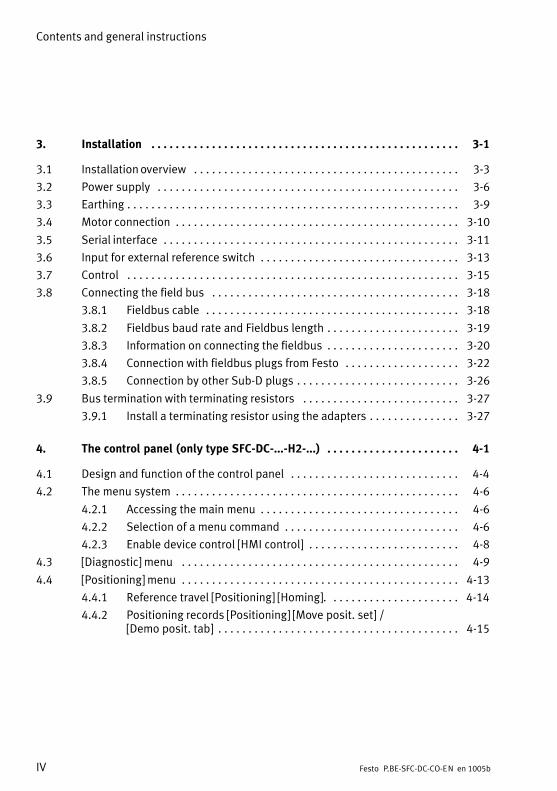
3. Installation 3−1 . . . . . . . . . . . . . . . . . . . . . . . . . . . . . . . . . . . . . . . . . . . . . . . . . . .
3.1 Installation overview 3−3 . . . . . . . . . . . . . . . . . . . . . . . . . . . . . . . . . . . . . . . . . . . .
3.2 Power supply 3−6 . . . . . . . . . . . . . . . . . . . . . . . . . . . . . . . . . . . . . . . . . . . . . . . . . .
3.3 Earthing 3−9 . . . . . . . . . . . . . . . . . . . . . . . . . . . . . . . . . . . . . . . . . . . . . . . . . . . . . . .
3.4 Motor connection 3−10 . . . . . . . . . . . . . . . . . . . . . . . . . . . . . . . . . . . . . . . . . . . . . . .
3.5 Serial interface 3−11 . . . . . . . . . . . . . . . . . . . . . . . . . . . . . . . . . . . . . . . . . . . . . . . . .
3.6 Input for external reference switch 3−13 . . . . . . . . . . . . . . . . . . . . . . . . . . . . . . . . .
3.7 Control 3−15 . . . . . . . . . . . . . . . . . . . . . . . . . . . . . . . . . . . . . . . . . . . . . . . . . . . . . . .
3.8 Connecting the field bus 3−18 . . . . . . . . . . . . . . . . . . . . . . . . . . . . . . . . . . . . . . . . .
3.8.1 Fieldbus cable 3−18 . . . . . . . . . . . . . . . . . . . . . . . . . . . . . . . . . . . . . . . . . .
3.8.2 Fieldbus baud rate and Fieldbus length 3−19 . . . . . . . . . . . . . . . . . . . . . .
3.8.3 Information on connecting the fieldbus 3−20 . . . . . . . . . . . . . . . . . . . . . .
3.8.4 Connection with fieldbus plugs from Festo 3−22 . . . . . . . . . . . . . . . . . . .
3.8.5 Connection by other Sub−D plugs 3−26 . . . . . . . . . . . . . . . . . . . . . . . . . . .
3.9 Bus termination with terminating resistors 3−27 . . . . . . . . . . . . . . . . . . . . . . . . . .
3.9.1 Install a terminating resistor using the adapters 3−27 . . . . . . . . . . . . . . .
4. The control panel (only type SFC−DC−...−H2−...) 4−1 . . . . . . . . . . . . . . . . . . . . . .
4.1 Design and function of the control panel 4−4 . . . . . . . . . . . . . . . . . . . . . . . . . . . .
4.2 The menu system 4−6 . . . . . . . . . . . . . . . . . . . . . . . . . . . . . . . . . . . . . . . . . . . . . . .
4.2.1 Accessing the main menu 4−6 . . . . . . . . . . . . . . . . . . . . . . . . . . . . . . . . .
4.2.2 Selection of a menu command 4−6 . . . . . . . . . . . . . . . . . . . . . . . . . . . . .
4.2.3 Enable device control [HMI control] 4−8 . . . . . . . . . . . . . . . . . . . . . . . . .
4.3 [Diagnostic] menu 4−9 . . . . . . . . . . . . . . . . . . . . . . . . . . . . . . . . . . . . . . . . . . . . . .
4.4 [Positioning] menu 4−13 . . . . . . . . . . . . . . . . . . . . . . . . . . . . . . . . . . . . . . . . . . . . . .
4.4.1 Reference travel [Positioning] [Homing]. 4−14 . . . . . . . . . . . . . . . . . . . . .
4.4.2 Positioning records [Positioning] [Move posit. set] / [Demo posit. tab] 4−15 . . . . . . . . . . . . . . . . . . . . . . . . . . . . . . . . . . . . . . . .
Contents and general instructions
VFesto P.BE−SFC−DC−CO−EN en 1005b
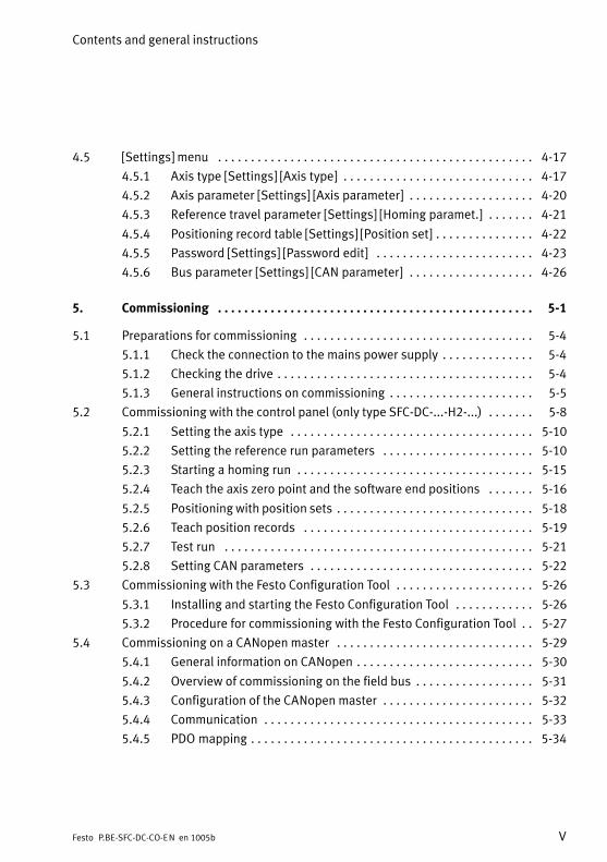
4.5 [Settings] menu 4−17 . . . . . . . . . . . . . . . . . . . . . . . . . . . . . . . . . . . . . . . . . . . . . . . .
4.5.1 Axis type [Settings] [Axis type] 4−17 . . . . . . . . . . . . . . . . . . . . . . . . . . . . .
4.5.2 Axis parameter [Settings] [Axis parameter] 4−20 . . . . . . . . . . . . . . . . . . .
4.5.3 Reference travel parameter [Settings] [Homing paramet.] 4−21 . . . . . . .
4.5.4 Positioning record table [Settings] [Position set] 4−22 . . . . . . . . . . . . . . .
4.5.5 Password [Settings] [Password edit] 4−23 . . . . . . . . . . . . . . . . . . . . . . . .
4.5.6 Bus parameter [Settings] [CAN parameter] 4−26 . . . . . . . . . . . . . . . . . . .
5. Commissioning 5−1 . . . . . . . . . . . . . . . . . . . . . . . . . . . . . . . . . . . . . . . . . . . . . . . .
5.1 Preparations for commissioning 5−4 . . . . . . . . . . . . . . . . . . . . . . . . . . . . . . . . . . .
5.1.1 Check the connection to the mains power supply 5−4 . . . . . . . . . . . . . .
5.1.2 Checking the drive 5−4 . . . . . . . . . . . . . . . . . . . . . . . . . . . . . . . . . . . . . . .
5.1.3 General instructions on commissioning 5−5 . . . . . . . . . . . . . . . . . . . . . .
5.2 Commissioning with the control panel (only type SFC−DC−...−H2−...) 5−8 . . . . . . .
5.2.1 Setting the axis type 5−10 . . . . . . . . . . . . . . . . . . . . . . . . . . . . . . . . . . . . .
5.2.2 Setting the reference run parameters 5−10 . . . . . . . . . . . . . . . . . . . . . . .
5.2.3 Starting a homing run 5−15 . . . . . . . . . . . . . . . . . . . . . . . . . . . . . . . . . . . .
5.2.4 Teach the axis zero point and the software end positions 5−16 . . . . . . .
5.2.5 Positioning with position sets 5−18 . . . . . . . . . . . . . . . . . . . . . . . . . . . . . .
5.2.6 Teach position records 5−19 . . . . . . . . . . . . . . . . . . . . . . . . . . . . . . . . . . .
5.2.7 Test run 5−21 . . . . . . . . . . . . . . . . . . . . . . . . . . . . . . . . . . . . . . . . . . . . . . .
5.2.8 Setting CAN parameters 5−22 . . . . . . . . . . . . . . . . . . . . . . . . . . . . . . . . . .
5.3 Commissioning with the Festo Configuration Tool 5−26 . . . . . . . . . . . . . . . . . . . . .
5.3.1 Installing and starting the Festo Configuration Tool 5−26 . . . . . . . . . . . .
5.3.2 Procedure for commissioning with the Festo Configuration Tool 5−27 . .
5.4 Commissioning on a CANopen master 5−29 . . . . . . . . . . . . . . . . . . . . . . . . . . . . . .
5.4.1 General information on CANopen 5−30 . . . . . . . . . . . . . . . . . . . . . . . . . . .
5.4.2 Overview of commissioning on the field bus 5−31 . . . . . . . . . . . . . . . . . .
5.4.3 Configuration of the CANopen master 5−32 . . . . . . . . . . . . . . . . . . . . . . .
5.4.4 Communication 5−33 . . . . . . . . . . . . . . . . . . . . . . . . . . . . . . . . . . . . . . . . .
5.4.5 PDO mapping 5−34 . . . . . . . . . . . . . . . . . . . . . . . . . . . . . . . . . . . . . . . . . . .

Contents and general instructions
VI Festo P.BE−SFC−DC−CO−EN en 1005b
5.5 Festo handling and positioning profile (FHPP) 5−37 . . . . . . . . . . . . . . . . . . . . . . . .
5.5.1 Supported operation modes 5−37 . . . . . . . . . . . . . . . . . . . . . . . . . . . . . . .
5.5.2 Composition of the cyclic I/O data (FHPP standard) 5−39 . . . . . . . . . . . .
5.5.3 Description of the I/O data (Record select) 5−41 . . . . . . . . . . . . . . . . . . .
5.5.4 Description of the I/O data (Direct mode) 5−42 . . . . . . . . . . . . . . . . . . . .
5.5.5 Description of the control bytes CCON, CPOS, CDIR 5−43 . . . . . . . . . . . .
5.5.6 Description of the status bytes SCON, SPOS, SDIR (RSB) 5−46 . . . . . . .
5.5.7 Examples of the I/O data 5−49 . . . . . . . . . . . . . . . . . . . . . . . . . . . . . . . . .
5.6 Sequence control as per FHPP standard 5−62 . . . . . . . . . . . . . . . . . . . . . . . . . . . .
5.6.1 Homing 5−62 . . . . . . . . . . . . . . . . . . . . . . . . . . . . . . . . . . . . . . . . . . . . . . . .
5.6.2 Jog mode 5−64 . . . . . . . . . . . . . . . . . . . . . . . . . . . . . . . . . . . . . . . . . . . . . .
5.6.3 Teaching via field bus 5−66 . . . . . . . . . . . . . . . . . . . . . . . . . . . . . . . . . . . .
5.6.4 Record selection (positioning mode) 5−68 . . . . . . . . . . . . . . . . . . . . . . . .
5.6.5 Direct mode (positioning mode, power operation) 5−73 . . . . . . . . . . . . .
5.6.6 Standstill monitoring 5−80 . . . . . . . . . . . . . . . . . . . . . . . . . . . . . . . . . . . . .
5.7 FHPP finite state machine 5−82 . . . . . . . . . . . . . . . . . . . . . . . . . . . . . . . . . . . . . . . .
5.7.1 Create ready status 5−84 . . . . . . . . . . . . . . . . . . . . . . . . . . . . . . . . . . . . . .
5.7.2 Positioning 5−85 . . . . . . . . . . . . . . . . . . . . . . . . . . . . . . . . . . . . . . . . . . . . .
5.8 Instructions on operation 5−87 . . . . . . . . . . . . . . . . . . . . . . . . . . . . . . . . . . . . . . . . .
6. Diagnosis and error treatment 6−1 . . . . . . . . . . . . . . . . . . . . . . . . . . . . . . . . . . . .
6.1 Diagnostics options 6−3 . . . . . . . . . . . . . . . . . . . . . . . . . . . . . . . . . . . . . . . . . . . . .
6.2 LED status displays 6−4 . . . . . . . . . . . . . . . . . . . . . . . . . . . . . . . . . . . . . . . . . . . . .
6.3 Malfunction messages 6−7 . . . . . . . . . . . . . . . . . . . . . . . . . . . . . . . . . . . . . . . . . . .
6.3.1 Overview 6−7 . . . . . . . . . . . . . . . . . . . . . . . . . . . . . . . . . . . . . . . . . . . . . .
6.3.2 Description of errors and warnings 6−9 . . . . . . . . . . . . . . . . . . . . . . . . .
6.4 Diagnostic memory 6−12 . . . . . . . . . . . . . . . . . . . . . . . . . . . . . . . . . . . . . . . . . . . . .
6.5 Diagnosis via CANopen 6−14 . . . . . . . . . . . . . . . . . . . . . . . . . . . . . . . . . . . . . . . . . .
6.5.1 Node guarding 6−14 . . . . . . . . . . . . . . . . . . . . . . . . . . . . . . . . . . . . . . . . . .
6.5.2 Emergency messages 6−15 . . . . . . . . . . . . . . . . . . . . . . . . . . . . . . . . . . . .
6.5.3 Diagnosis via parameter channel 6−16 . . . . . . . . . . . . . . . . . . . . . . . . . . .

Contents and general instructions
VIIFesto P.BE−SFC−DC−CO−EN en 1005b
A. Technical appendix A−1 . . . . . . . . . . . . . . . . . . . . . . . . . . . . . . . . . . . . . . . . . . . . .
A.1 Technical Data A−3 . . . . . . . . . . . . . . . . . . . . . . . . . . . . . . . . . . . . . . . . . . . . . . . . .
A.2 Accessories A−5 . . . . . . . . . . . . . . . . . . . . . . . . . . . . . . . . . . . . . . . . . . . . . . . . . . . .
A.3 Converting the units of measurement A−7 . . . . . . . . . . . . . . . . . . . . . . . . . . . . . . .
B. Reference Festo Handling and Positioning Profile (FHPP) B−1 . . . . . . . . . . . . .
B.1 Festo Parameter Channel (FPC) B−3 . . . . . . . . . . . . . . . . . . . . . . . . . . . . . . . . . . . .
B.1.1 Composition of the cyclic I/O data (FHPP−FPC) B−3 . . . . . . . . . . . . . . . .
B.1.2 Request identifiers, response identifiers and error numbers B−5 . . . . .
B.1.3 Rules for request−response processing B−8 . . . . . . . . . . . . . . . . . . . . . .
B.1.4 Example of parametrisation B−10 . . . . . . . . . . . . . . . . . . . . . . . . . . . . . . .
B.2 Reference parameters according to FHPP B−12 . . . . . . . . . . . . . . . . . . . . . . . . . . .
B.2.1 Parameter groups B−12 . . . . . . . . . . . . . . . . . . . . . . . . . . . . . . . . . . . . . . .
B.2.2 Object overview (Parameter number (PNU)) B−13 . . . . . . . . . . . . . . . . . .
B.2.3 Representation of the parameter entries B−17 . . . . . . . . . . . . . . . . . . . . .
B.2.4 Device data � Standard parameters B−18 . . . . . . . . . . . . . . . . . . . . . . . . .
B.2.5 Device data � Extended parameters B−19 . . . . . . . . . . . . . . . . . . . . . . . . .
B.2.6 Diagnostics B−22 . . . . . . . . . . . . . . . . . . . . . . . . . . . . . . . . . . . . . . . . . . . .
B.2.7 Process data B−26 . . . . . . . . . . . . . . . . . . . . . . . . . . . . . . . . . . . . . . . . . . .
B.2.8 Record list B−28 . . . . . . . . . . . . . . . . . . . . . . . . . . . . . . . . . . . . . . . . . . . . .
B.2.9 Project data � General B−33 . . . . . . . . . . . . . . . . . . . . . . . . . . . . . . . . . . . .
B.2.10 Project data � Force mode B−36 . . . . . . . . . . . . . . . . . . . . . . . . . . . . . . . .
B.2.11 Project data � Teaching B−37 . . . . . . . . . . . . . . . . . . . . . . . . . . . . . . . . . . .
B.2.12 Project data � Jog mode B−38 . . . . . . . . . . . . . . . . . . . . . . . . . . . . . . . . . .
B.2.13 Project data � Direct mode (Positioning mode) B−41 . . . . . . . . . . . . . . . .
B.2.14 Project data � Direct mode (Force mode) B−42 . . . . . . . . . . . . . . . . . . . . .
B.2.15 Axis parameter electric drive 1 � Mechanical B−44 . . . . . . . . . . . . . . . . .
B.2.16 Axis parameter electric drive 1 � Homing B−50 . . . . . . . . . . . . . . . . . . . .
B.2.17 Axis parameters electric drives 1 � controller B−52 . . . . . . . . . . . . . . . . .
B.2.18 Axis parameters electric drive 1 � Electronics Name plate B−58 . . . . . . .
B.2.19 Axis parameters electric drive 1 � Standstill monitoring B−60 . . . . . . . . .

Contents and general instructions
VIII Festo P.BE−SFC−DC−CO−EN en 1005b
C. Reference CANopen and Command Interpreter (CI) C−1 . . . . . . . . . . . . . . . . . . .
C.1 Overview of CANopen objects C−3 . . . . . . . . . . . . . . . . . . . . . . . . . . . . . . . . . . . . .
C.1.1 Representation of the parameter entries C−9 . . . . . . . . . . . . . . . . . . . . .
C.1.2 Communication Profile Area (1xxxh) C−10 . . . . . . . . . . . . . . . . . . . . . . . .
C.1.3 Manufacturer Specific Profile Area (2xxxh) C−18 . . . . . . . . . . . . . . . . . . .
C.1.4 DS 402: Standardised Device Profile Area (6xxxh) C−27 . . . . . . . . . . . . .
C.2 Status machine as per DS 402 C−42 . . . . . . . . . . . . . . . . . . . . . . . . . . . . . . . . . . . . .
C.3 Data transmission with the Command Interpreter C−47 . . . . . . . . . . . . . . . . . . . . .
C.3.1 Procedure C−47 . . . . . . . . . . . . . . . . . . . . . . . . . . . . . . . . . . . . . . . . . . . . .
C.3.2 Composition of the CI commands C−49 . . . . . . . . . . . . . . . . . . . . . . . . . . .
C.3.3 Checking the data C−53 . . . . . . . . . . . . . . . . . . . . . . . . . . . . . . . . . . . . . . .
C.4 CI objects C−55 . . . . . . . . . . . . . . . . . . . . . . . . . . . . . . . . . . . . . . . . . . . . . . . . . . . . .
C.4.1 Object overview (Index, Subindex) C−55 . . . . . . . . . . . . . . . . . . . . . . . . . .
C.4.2 Representation of the parameter entries C−60 . . . . . . . . . . . . . . . . . . . . .
C.4.3 Additional CI objects C−61 . . . . . . . . . . . . . . . . . . . . . . . . . . . . . . . . . . . . .
D. Index D−1 . . . . . . . . . . . . . . . . . . . . . . . . . . . . . . . . . . . . . . . . . . . . . . . . . . . . . . . . .

Contents and general instructions
IXFesto P.BE−SFC−DC−CO−EN en 1005b
Intended use
The motor controller (Single Field Controller, single axis fieldcontroller) type SFC−DC−...−CO serves as a position controllerand position servo for the electric mini slide type SLTE,the�electric gripper HGPLE and the gripper and rotarymodules GEH and DEF of Sommer Co. with activation via theCANopen fieldbus. The fieldbus interface supports the Festo Fieldbus Handlingand Positioning Profile (FHPP) and alternatively permits theuse of the CIA−defined profile DS 402.
It is absolutely necessary to observe the �Safety instructions"as well as the designated use of the relevant components andmodules. Please also observe the safety instructionsspecified in the operating instructions for the componentsused.
The SFC−DC and the connectable modules and lines may onlybe used as follows:
� as intended
� only in an industrial environment
� in its original condition without unauthorisedmodifications. Only the conversions or modificationsdescribed in the documentation supplied with the productare permitted.
� in perfect technical condition.
If conventional accessory components such as sensors andactuators are connected, the specified limits for pressures,temperatures, electrical data, torques etc. should beobserved.
Please observe the standards specified in the relevantchapters and comply with the regulations of the tradeassociation and the German Technical Control Board (TÜV),the VDE conditions as well as the relevant nationalregulations.

Contents and general instructions
X Festo P.BE−SFC−DC−CO−EN en 1005b
Safety instructions
When commissioning and programming positioning systems,the safety regulations in this manual as well as those in theoperating instructions for the other components used shouldbe observed unconditionally.
The user must make sure that nobody is within the sphere ofinfluence of the connected actuators or axis system.Access�to the potential danger area must be prevented bysuitable measures, such as barriers and warning signs.
WarningElectric axes can move suddenly with high force and athigh speed. Collisions can lead to serious injury to peopleand damage to components.
Make sure that nobody can reach into the sphere ofinfluence of the axes or other connected actuators and thatno items are within the positioning range while the systemis connected to energy sources.
If used in safety−relevant applications, additional measuresare necessary, e.g. in Europe, the standards listed underthe EU machine guidelines must be observed. Withoutadditional measures in accordance with statutoryminimum requirements, the product is not suitable for usein safety−related sections of control systems.
WarningErrors in parametrisation can cause injury to people anddamage to property.
Enable the controller only if the axis system has beencorrectly installed and parametrised.

Contents and general instructions
XIFesto P.BE−SFC−DC−CO−EN en 1005b
Target group
This manual is intended exclusively for technicians trained incontrol and automation technology, who have experience ininstalling, commissioning, programming and diagnosingpositioning systems.
Service
Please consult your local Festo Service or write to thefollowing e−mail address if you have any technical problems:
Scope of delivery
The scope of delivery of the motor controller type SFC−DCincludes the following:
� Motor controller, optionally with control panel
� Operating package on CD ROM:
� User documentation (descriptions)
� Festo Configuration Tool with SFC−DC plug−in
� User documentation (descriptions)
The following are available as accessories (see appendix A.2):
� Connecting cables and fieldbus plugs
� Mounting attachments
� User documentation in paper form

Contents and general instructions
XII Festo P.BE−SFC−DC−CO−EN en 1005b
Important user instructions
Danger categories
This manual contains instructions on the possible dangerswhich may occur if the product is not used correctly.These�instructions are marked (Warning, Caution, etc.),printed on a shaded background and marked additionallywith a pictogram. A distinction is made between the followingdanger warnings:
WarningThis means that failure to observe this instruction mayresult in serious personal injury or damage to property.
CautionThis means that failure to observe this instruction mayresult in personal injury or damage to property.
NoteThis means that failure to observe this instruction mayresult in damage to property.
The following pictogram marks passages in the text whichdescribe activities with electrostatically sensitivecomponents.
Electrostatically sensitive components may be damaged ifthey are not handled correctly.

Contents and general instructions
XIIIFesto P.BE−SFC−DC−CO−EN en 1005b
Marking special information
The following pictograms mark passages in the textcontaining special information.
Pictograms
Information:Recommendations, tips and references to other sources ofinformation.
Accessories:Information on necessary or sensible accessories for theFesto product.
Environment:Information on environment−friendly use of Festo products.
Text markings
· The bullet indicates activities which may be carried out inany order.
1. Figures denote activities which must be carried out in thenumerical order specified.
� Hyphens indicate general activities.
Contents and general instructions
XIV Festo P.BE−SFC−DC−CO−EN en 1005b
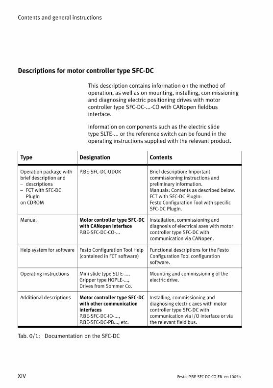
Descriptions for motor controller type SFC−DC
This description contains information on the method ofoperation, as well as on mounting, installing, commissioningand diagnosing electric positioning drives with motorcontroller type SFC−DC−...−CO with CANopen fieldbusinterface.
Information on components such as the electric slidetype�SLTE−... or the reference switch can be found in theoperating instructions supplied with the relevant product.
Type Designation Contents
Operation package withbrief description and� descriptions� FCT with SFC−DC
PlugInon CDROM
P.BE−SFC−DC−UDOK Brief description: Importantcommissioning instructions andpreliminary information.Manuals: Contents as described below.FCT with SFC−DC PlugIn:Festo�Configuration Tool with specificSFC−DC PlugIn.
Manual Motor controller type SFC−DCwith CANopen interfaceP.BE−SFC−DC−CO−...
Installation, commissioning anddiagnosis of electrical axes with motorcontroller type SFC−DC withcommunication via CANopen.
Help system for software Festo Configuration Tool Help(contained in FCT software)
Functional descriptions for the FestoConfiguration Tool configurationsoftware.
Operating instructions Mini slide type SLTE−..., Gripper type HGPLE−..., Drives from Sommer Co.
Mounting and commissioning of theelectric drive.
Additional descriptions Motor controller type SFC−DCwith other communicationinterfacesP.BE−SFC−DC−IO−..., P.BE−SFC−DC−PB..., etc.
Installing, commissioning anddiagnosing electric axes with motorcontroller type SFC−DC withcommunication via I/O interface or viathe relevant field bus.
Tab.�0/1: Documentation on the SFC−DC

Contents and general instructions
XVFesto P.BE−SFC−DC−CO−EN en 1005b
Information on the version
The hardware version indicates the version status of theSFC−DC’s electronics. The firmware version specifies the version status of theoperating system of the SFC−DC.
You can find the specifications on the version status asfollows:
� Hardware version and firmware version in theFesto�Configuration Tool with active device connection tothe SFC−DC under �Device data"
� Firmware version on the control panel under [Diagnostic][Software information].
Firmwareversion from
What is new? Which FCT PlugIn?
V4.02 Motor controller with CANopen interface type SFC−DC−...−COfrom hardware version 2.0, supports 1)
� electric mini−slides e.g. type SLTE−10−.../SLTE−16−...� electric grippers, e.g. type HGPLE−25−40� electric grippers and rotary modules of Sommer Co.In addition, user−defined axis lengths, gear variants andspindle pitches are supported for customized solutions.Extended parameters, see appendix B.
From SFC−DCV3.0.0
V2.00 Motor controller with CANopen interface of type SFC−DC−...−CO,supports� electric mini−slides e.g. type SLTE−10−.../SLTE−16−...� electric grippers, e.g. type HGPLE−25−40Support of force control for the gripper with additionalparameters.Changed objects: 2040h, 2041h (previously 6067h, 6068h).Firmware download possible via FCT.
From SFC−DCV2.3.0
V1.10 Motor controller with CANopen interface of type SFC−DC−...−COsupports� electric mini−slides, e.g., type SLTE−10−... / SLTE−16−...
From SFC−DCV2.1.0
1) Support of additional drives is in preparation. Currently supported drives as per [Axis type]listing�on control panel (see chapter 4.5, Tab.�4/15 and Tab.�4/16) or FCT PlugIn(settings�for��Axis�type" and �Size").
Tab.�0/2: Firmware designs

Contents and general instructions
XVI Festo P.BE−SFC−DC−CO−EN en 1005b
Product−specific terms and abbreviations
The following product−specific terms and abbreviations areused in this manual.
For fieldbus specific abbreviations see following Tab.�0/4.
Term / abbreviation Significance
Axis Mechanical component of a drive that transfers the drive force for themotion. An axis enables the attachment and guiding of the work loadand, if necessary, the attachment of a reference switch.
Axis zero point (AZ) Reference point for the software end positions and the project zeropoint PZ. The axis zero point AZ is defined by a preset distance (offset)from the reference point REF.
Controller Contains power electronics + regulator + position controller, evaluatessensor signals, calculates movements and forces and provides thepower supply for the motor via the power electronics.
Drive Complete actuator, consisting of motor, encoder and axis, optionallywith a gearbox, if applicable with controller. The electric mini slide typeSLTE is an integrated unit consisting of a motor, encoder, gear unit andaxis.
EMC Electromagnetic compatibility (EMC).
Encoder With the SFC−DC: magnetic pulse generator (rotor position transducer).The electric signals generated are sent to the controller, which thencalculates the position and speed on the basis of the signals received.
Festo Configuration Tool(FCT)
Software with uniform project and data management for all supporteddevice types. The special requirements of a device type are supportedwith the necessary descriptions and dialogues by means of plug−ins.
Festo Handling andPositioning Profile (FHPP)
Uniform Fieldbus data profile for positioning controllers from Festo.
Festo Parameter Channel(FPC)
Parameter access according to the �Festo Handling and PositioningProfile" (I/O�messaging, optionally additional 8 bytes I/O)
FHPP standard Defines the sequence control as per the �Festo Handling andPositioning Profile" (I/O Messaging 8 Byte I/O)

Contents and general instructions
XVIIFesto P.BE−SFC−DC−CO−EN en 1005b
Term / abbreviation Significance
Force control(Profile Torque Mode)
Operating mode for executing a direct positioning task with poweroperation (open loop transmission control) with motor currentregulation.
HGPLE... Type designation, electric gripper.
HMI Human−Machine Interface (MMI), e.g.�control panel with LC display andoperating buttons.
Homing Positioning procedure in which the reference point and therefore theorigin of the measuring reference system of the axis are defined.
Homing (Homing mode)
Defining the measuring reference system of the axis
Homing method Method for defining the reference position: Against a fixed stop(overload current evaluation/speed evaluation) or with referenceswitch.
IOI/O
Input.Output.Input and/or output.
Jog mode Manual positioning in positive or negative direction (only on fieldbusvariants of the SFC−DC via the fieldbus or only with FCT or control panel).
Logic 0 0 V present at input or output (positive logic, corresponds to LOW).
Load voltage, logic voltage The load voltage supplies the power electronics of the controller andthereby the motor. The logic voltage supplies the evaluation andcontrol logic of the controller.
Logic 1 24 V present at input or output (positive logic, corresponds to HIGH).
MMI Human−Machine−Interface, see �HMI".
Operating mode Type of controller or internal operating mode of the controller.� Type of control: Record Select, Direct Mode� Operation mode of the controller: Position Profile Mode,
Profile Torque Mode ...� Predefined sequences: Homing Mode, Demo Mode, etc.
PLC Programmable logic controller; controller (also IPC: industrial PC).
Positioning mode (Profile Position mode)
Operating mode for executing a position set or a direct positioning taskwith position control (closed loop position control)

Contents and general instructions
XVIII Festo P.BE−SFC−DC−CO−EN en 1005b
Term / abbreviation Significance
Positioning record Positioning command defined in the position set table, consisting oftarget position, positioning mode, positioning speed and accelerations.
Project zero point (PZ) Reference point for all positions in positioning tasks. The project zeropoint PZ forms the basis for all absolute position specifications(e.g.�in�the position set table or with direct control via the controller ordiagnostic interface). The project zero point PZ is defined by a presetdistance (offset) from the axis zero point.
Reference point (REF) Point of reference for the incremental measuring system.The�reference�point defines a known orientation or position within thepositioning path of the drive.
Reference switch External sensor used for ascertaining the reference position andconnected directly to the controller.
SLTE... Type designation, electric slide.
Software end position Programmable stroke limitation (basis point = axis zero point)� Software end position, positive:
max. limit position of the stroke in positive direction; must not beexceeded during positioning.
� Software end position, negative:min. limit position in negative direction; must not be fallen short ofduring positioning.
Teach mode Operating mode for setting positions by moving to the target position,e.g. when creating position sets.
Tab.�0/3: Index of terms and abbreviations for the SFC−DC

Contents and general instructions
XIXFesto P.BE−SFC−DC−CO−EN en 1005b
CANopen specific terms and abbreviations
Term / abbreviation Significance
0x1234 or 1234h Hexadecimal numbers are marked by a prefixed �0x" or by asuffixed��h".
BCD Binary coded decimal
EDS Electronic Data Sheet; contains the specific properties of the slave(e.g. number of I/Os, parameters, etc.).
LSB Least significant bit (lower−value bit)
MSB Most significant bit (higher−value bit)
Terminating resistor Resistor for minimising signal reflections. Terminating resistors must beinstalled or switched in at the end of bus segment cables.
Tab.�0/4: Index of CANopen terms and abbreviations

Contents and general instructions
XX Festo P.BE−SFC−DC−CO−EN en 1005b

System summary
1−1Festo P.BE−SFC−DC−CO−EN en 1005b
Chapter 1

1. System summary
1−2 Festo P.BE−SFC−DC−CO−EN en 1005b
Contents
1.1 Positioning with electric drives 1−3 . . . . . . . . . . . . . . . . . . . . . . . . . . . . . . . . . . . .
1.2 Components 1−7 . . . . . . . . . . . . . . . . . . . . . . . . . . . . . . . . . . . . . . . . . . . . . . . . . . .
1.3 Control and regulating functions 1−9 . . . . . . . . . . . . . . . . . . . . . . . . . . . . . . . . . . .
1.4 Operational safety 1−11 . . . . . . . . . . . . . . . . . . . . . . . . . . . . . . . . . . . . . . . . . . . . . .
1.5 Structure of the SFC−DC 1−12 . . . . . . . . . . . . . . . . . . . . . . . . . . . . . . . . . . . . . . . . . .
1.6 Dimension reference system 1−14 . . . . . . . . . . . . . . . . . . . . . . . . . . . . . . . . . . . . . .
1.6.1 Basis points and work range 1−14 . . . . . . . . . . . . . . . . . . . . . . . . . . . . . .
1.6.2 Signs and directions 1−17 . . . . . . . . . . . . . . . . . . . . . . . . . . . . . . . . . . . . .
1.6.3 Homing 1−18 . . . . . . . . . . . . . . . . . . . . . . . . . . . . . . . . . . . . . . . . . . . . . . . .
1.7 Fieldbus communication � FHPP and DS 402 1−23 . . . . . . . . . . . . . . . . . . . . . . . . .
1.7.1 Data exchange in CANopen 1−23 . . . . . . . . . . . . . . . . . . . . . . . . . . . . . . .
1.7.2 Data profiles FHPP and DS 402 1−24 . . . . . . . . . . . . . . . . . . . . . . . . . . . .

1. System summary
1−3Festo P.BE−SFC−DC−CO−EN en 1005b
1.1 Positioning with electric drives
The motor controller type SFC−DC−...−CO with CANopenfieldbus interface enables positioning of the connectedelectric drive:
� as per the Festo Handling and Positioning Profile:
� via record selection: in max. 31 position sets (+�homing) with separatelyadjustable speeds, accelerations and decelerations.
� via Direct mode: The positioning task is transmitted directly in the I/Otelegram via the fieldbus with the appropriatesetpoint values.
� as per device profile DS 402 from the userorganisation�CIA.
You can parametrise and commission the SFC−DC as follows:
� Directly via the control panel (only type SFC−DC−...H2−...).
� Via the RS232 interface (with FCT software).
� Via fieldbus (see chapter 5.4 ff ).
The link to a higher−level PLC/IPC in operation is made overthe CANopen fieldbus.

1. System summary
1−4 Festo P.BE−SFC−DC−CO−EN en 1005b
Control panel (only type SFC−DC−...−H2−...)
The control panel offers all functions necessary forcommissioning, parametrisstion, diagnostics and operationdirectly at the SFC−DC−...
The control panel provides the necessary input masks viamenus for editing positioning records and parameters.If�your�positioning system is set up completely, you can usethe Teach functions to move easily to positions and transferthem to the position record table.
You will find information on the control panel’s operatingelements and menu structure in chapter 4, and instructionsfor commissioning using the control panel starting atchapter�5.2.
Festo Configuration Tool (FCT)
The Festo Configuration Tool (abbreviated as FCT) is thesoftware platform for configuring and commissioningdifferent components and devices from Festo.
The FCT consists of the following components:
� A framework providing a program starting and entry pointwith uniform project and data management for allsupported device types.
� A PlugIn for each of the special demands of a device type(e.g. SFC−DC) with the necessary descriptions anddialogues. The PlugIns are managed and started fromwithin the framework.
PlugIn SFC−DC for the FCT supports all the steps necessaryfor commissioning an SFC−DC.
An overview of commissioning with the FCT can be found inchapter 5.3.2. The help for the FCT contains the complete information onoperating the Festo Configuration Tool. The device−specificPlugIns each have their own help files.

1. System summary
1−5Festo P.BE−SFC−DC−CO−EN en 1005b
Functions Controlpanel
FCT Fieldbus
Parametrisation � Selecting the axis type and theassociated axis parameters
� Uploading/downloading ofconfiguration data
� Saving different configurations inprojects
x
��
x
xx
x
x�
Commissioning � Homing� Jog mode� Teaching of positions� Travel in individual steps� Starting and stopping positioning
procedures during commissioning� Extended test functions
e.g status displays� Testing or demonstrating the
positioning records
x(x)x�x
(x)
x
xxxxx
x
x
xxxxx
x
x
Record selection � Creation of a position set table forpositioning operation with set number,target position, positioning mode,positioning speed, acceleration, deceleration
� Executing a positioning record
x
x
x
x
x
x
Direct mode � Parametrising the direct job forpositioning and force mode
� Executing a direct job
�
�
x
x
x
x
Diagnostics /Service
� Reading and displaying diagnostic data� Read and display fault buffer
x
�
x
x
x
x
Tab.�1/1: Commissioning options � Functions

1. System summary
1−6 Festo P.BE−SFC−DC−CO−EN en 1005b
All values are entered or displayed according to themeasuring units set for either the Festo Configuration Tool orthe control panel.
Units of measurement Access via:
Controlpanel
FCT Fieldbus
Electric minislide, gripper
Metric Metric units of measurement, e.g. mm, mm/s, mm/s2
x x �
Inches 1) Imperial units ofmeasurement, e.g. inch, inch/s, inch/s2
� x �
Increments Increment−based units, e.g. inc, inc/s, inc/s2
� � x
Rotary module ° (degrees) Units of measurement indegrees, e.g. °, °/s, °/s2
x x �
Increments Increment−based units ofmeasurement,e.g.�inc,�inc/s,�inc/s2
� � x
1) Only with FCT; must be established when setting up the project.
The setting of the units of measurement influences only thedisplay in the Festo Configuration Tool. All parameters aresaved in the SFC−DC in increments (inc, inc/s, inc/s2 ...) andare not converted until they are written or read. Dimensionstransmitted directly via the Fieldbus or RS232 relate to anincrement basis (for conversion see appendix A.3).

1. System summary
1−7Festo P.BE−SFC−DC−CO−EN en 1005b
1.2 Components
1 Higher−ordercontroller / Fieldbus master
2 Software level:Festo�ConfigurationTool
3 Controller level:SFC−DC
4 Motor drive level(e.g.�SLTE)
1
2
3
4
Fig.�1/1: Schematic diagram of an electrical positioning system with the SFC−DC−...−CO

1. System summary
1−8 Festo P.BE−SFC−DC−CO−EN en 1005b
In order to set up an electric drive with the SFC−DC,you�will�require the following components:
Controller SFC−DC, optionally with control panel.
Drive Electric drive with motor, accessories and, if necessary,further components for the drive, e.g. mountingattachments, etc.
The SFC−DC supports the following drives (see also �Information on the Version", Tab.�0/2).
Supporteddrives
Description Permissible mountingposition
SLTE−... Electric mini−slidetype�SLTE−...
Any
HGPLE−... Electric gripper. Any
GEH6..., DEF... Electric gripper androtary modules ofSommer Co.
Any
Other only after consultation with Festo.
Power supply unit For logic and load voltage supply: 24 VDC
Power supply line For supplying the SFC−DC with operating and load voltage(see Accessories, appendix A.2)
Motor cable For connecting the drive to the SFC−DC(see�Accessories,�appendix A.2)
Fieldbus plug withfieldbus cable
For information transfer between the higher−order controllerand the SFC−DC (see accessories, appendix A.2)
Programming cable For transfer of information between the PC and theSFC−DC−... (see Accessories, appendix A.2)
Reference switch Optional: Suitable sensor (normally open) as referenceswitch, e.g. type SMT−10.
For positioning systems, Festo offers accessories suited tothe drive packages (see Festo delivery program or catalogue).

1. System summary
1−9Festo P.BE−SFC−DC−CO−EN en 1005b
1.3 Control and regulating functions
In the positioning mode, a certain position is specified towhich the motor must move. The current position is obtainedfrom the information supplied by the internal incrementsensor (magnetic encoder). The position is derived from thegear reduction and the shaft pitch.
The deviation of the position is processed in the positioncontroller and passed on to the speed regulator.
1 Controller SFC−DC
2 Controller
3 Nominal valuegenerator
4 Position controller
5 Speed regulator
6 Current Control
7 Output stage
8 Signal converter
MP PI
3
8
4
5 6 7
1
2
P
Fig.�1/2: Simplified technical representation of the cascade regulator function
The controller takes over the following tasks:
� Activation via FHPP or DS 402,
� Specification of the nominal values,
� Control of the following variables: position, speed,acceleration, current (power).

1. System summary
1−10 Festo P.BE−SFC−DC−CO−EN en 1005b
Profile Position Mode Positioning modeOperating mode for executing a position set or a directpositioning task with position control(closed�loop�position�control)The target position defines the position to which the drivecontroller is to move. The target position is interpreted eitheras an absolute or relative specification. The set targetposition is transferred to the nominal value generator.This�generates a nominal position value for the positioncontroller. For position control, the current settings for speed,acceleration, braking deceleration, etc. are taken intoaccount.
Profile Torque Mode Force controlForce control (open loop transmission control) with motorcurrent regulation. This operating mode enables an externalnominal torque value (relative to the rated motor current) tobe specified to the controller. Power control takes placeindirectly via the regulation of the motor current.All�specifications on forces/torques refer to the rated motortorque or current.
Homing mode Positioning travel for referencing the mechanical basissystem.
For commissioning, testing or demonstration, the followingfunctions are also available via the control panel of theSFC−DC−...H2−...:
� Positioning travel for defining the target position of aposition set (Teach mode)
� Positioning travel for testing all position sets in theposition set table (Demo posit. tab.)
� Positioning travel for testing a certain positioning set inthe positioning set table (Move posit. set).

1. System summary
1−11Festo P.BE−SFC−DC−CO−EN en 1005b
1.4 Operational safety
A complex system of sensors and monitoring functionsensures operational reliability:
� Temperature monitoring (measurement of the power endstage temperature),
� Voltage monitoring, detection of:
� Faults in the logic voltage supply
� Undervoltages in the load voltage supply
� I2t monitoring / overload protection
� Drag fault monitoring
� Software end position recognition.
NoteCheck within the framework of your emergency stopconcept to ascertain which measures are required to putyour machine/system into a safe status in the event ofEMERGENCY STOP (e.g. switching off the operatingvoltage).
The SFC−DC has a separate logic voltage supply.
· If an EMERGENCY STOP circuit is required for yourapplication use additional separate safety limit switches(e.g. NC switches connected in series).
· Use software end positions and, if necessary, externalsafety limit switches as well as additional appropriatemechanical stops in order to make sure that the axisalways lies within the permitted positioning range.

1. System summary
1−12 Festo P.BE−SFC−DC−CO−EN en 1005b
1.5 Structure of the SFC−DC
1 Control panel (onlytype SFC−DC−...−H2−...:LC display andmembrane keypad)
2 Electrical connections
3 Status displays(LEDs)
1
2
3
Fig.�1/3: Single field controller SFC−DC
Control panel The control panel possesses an LCD graphics display(128�x�64 dots). It is operated using a touch−sensitivekeypad with 4�keys, allowing access to all functions bymeans of menus.
Remove the protective foil from the display beforecommissioning.
1 LC display
2 Touch−sensitivekeypad
3 LEDs
1 2
3
Fig.�1/4: Control panel and status display on the SFC−DC−...−H2−...
1. System summary
1−13Festo P.BE−SFC−DC−CO−EN en 1005b
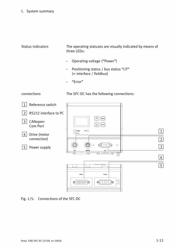
Status indicators The operating statuses are visually indicated by means ofthree�LEDs:
� Operating voltage (�Power")
� Positioning status / bus status �I/F" (= interface / fieldbus)
� �Error"
connections The SFC−DC has the following connections:
1 Reference switch
2 RS232 interface to�PC
3 CANopen−Com Port
4 Drive (motorconnection)
5 Power supply
1
2
3
4
5
Fig.�1/5: Connections of the SFC−DC
1. System summary
1−14 Festo P.BE−SFC−DC−CO−EN en 1005b
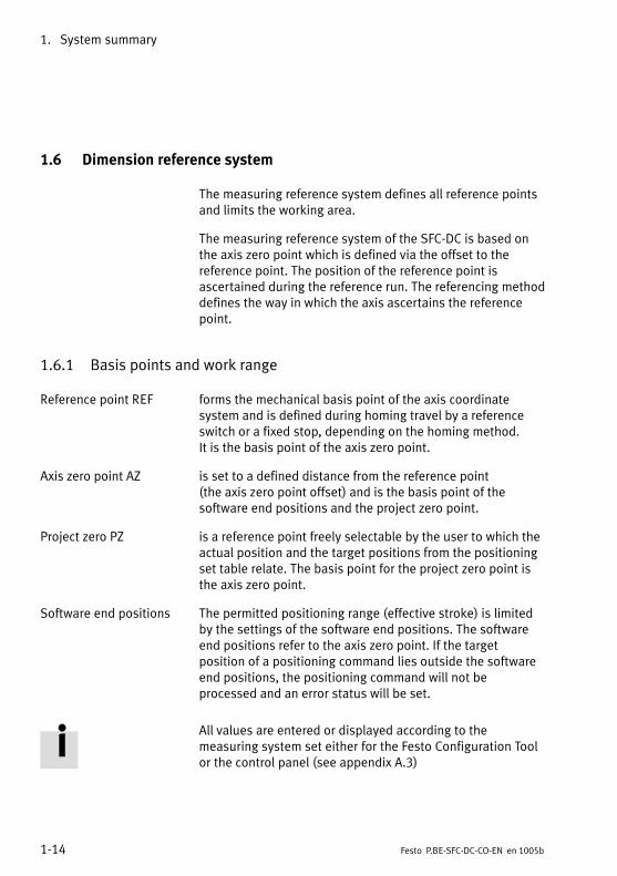
1.6 Dimension reference system
The measuring reference system defines all reference pointsand limits the working area.
The measuring reference system of the SFC−DC is based onthe axis zero point which is defined via the offset to thereference point. The position of the reference point isascertained during the reference run. The referencing methoddefines the way in which the axis ascertains the referencepoint.
1.6.1 Basis points and work range
Reference point REF forms the mechanical basis point of the axis coordinatesystem and is defined during homing travel by a referenceswitch or a fixed stop, depending on the homing method.It�is�the basis point of the axis zero point.
Axis zero point AZ is set to a defined distance from the reference point(the�axis�zero point offset) and is the basis point of thesoftware end positions and the project zero point.
Project zero PZ is a reference point freely selectable by the user to which theactual position and the target positions from the positioningset table relate. The basis point for the project zero point isthe axis zero point.
Software end positions The permitted positioning range (effective stroke) is limitedby the settings of the software end positions. The softwareend positions refer to the axis zero point. If the targetposition of a positioning command lies outside the softwareend positions, the positioning command will not beprocessed and an error status will be set.
All values are entered or displayed according to themeasuring system set either for the Festo Configuration Toolor the control panel (see appendix A.3)

1. System summary
1−15Festo P.BE−SFC−DC−CO−EN en 1005b
Reference coordinates and working area 1)
a d
b c
REF AZ PZ
LSE USE
2
1SLTE... 1)
USELSE eTP/AP
PZ
REF Reference point: The measuring reference point to which movement is made duringreference travel and to which the axis zero point refers.
AZ Axis zero point: Dimension reference point for the project zero point and the software endpositions. The basis point for the axis zero point is the reference point.
PZ Project zero point: Dimension reference point for all absolute position specifications(e.g.�in the position set table or with direct control via the controller or diagnosticinterface). The basis point for the project zero point is the axis zero point.
USE Upper software end position
LSE Lower software end position
TP/AP Target/actual position
a Offset axis zero point: Defined distance of the axis zero point from the reference point.
b, c Software end positions: Limits for the permitted positioning range (effective stroke).If�the�target position of a positioning command lies outside the software end positions,the positioning command will not be processed and a fault status will be displayed.
d Offset project zero point: Defined distance of the project zero point from the axis zero point.
e Offset of the (current) position to the project zero point
1 Effective stroke: permitted positioning range. The work range of the axis is thereby defined.
2 Nominal stroke: Nominal stroke of the drive in use; see technical data for the drive(for�the SLTE the stroke specified in the order).
1) Vector representation for the homing method: Example of fixed stop, negative

1. System summary
1−16 Festo P.BE−SFC−DC−CO−EN en 1005b
Reference coordinates and working area 1)
a
b c
dREF AZ PZ
1
2
LSE USE
HGPLE−... / GEH6... 1)
PZ
LSE USEe
TP/AP
DEF... 2)
ab
c
d
REF
AZ PZ
12
1) Vector representation for the homing method: Example of fixed stop, negative2) Vector representation for the homing method: Example, reference switch negative
Tab.�1/2: Dimension reference system

1. System summary
1−17Festo P.BE−SFC−DC−CO−EN en 1005b
Reference point Calculation rule
Axis zero point AZ = REF + a
Project zero point PZ = AZ + d = REF + a + d
Lower software end position LSE = AZ + b = REF + a + b
Upper software end position USE = AZ + c = REF + a + c
Target/actual position TP, AP = PZ + e = AZ + d + e = REF + a + d + e
Tab.�1/3: Calculating specifications for the dimension reference system
1.6.2 Signs and directions
All offsets and position values are (signed) vectors and mustbe adjusted to match the position of the respective referencepoint.
The direction in which the work load moves depends on thegearbox, the spindle type (left/right−hand turning), the signfor the position specifications (+/−) and the setting of the�Direction reversal" parameter.
The +/− active direction of the vectors can be assigned to thedirection of rotation of the motor shaft (view on the motorshaft). The factory setting is �+" for motor rotation in aclockwise direction; �−" for motor rotation in ananti−clockwise direction.
Value 1) SLTE−... HGPLE−... / GEH6... DEF...
+ Positive values face from thebasis point in the directionaway from the motor.
Positive values face from thereference point in the directionof the closed gripper jaws.
Clockwise, lookingtowards the motorshaft.
− Negative values face from thebasis point in the directiontowards the motor.
Negative values face from thereference point in the directionof the open gripper jaws.
Anti−clockwise,looking towards themotor shaft.
1) With factory setting. The assignment can be reversed (see also appendix B.2.15, PNU 1000,Object 607E). After reversal a new homing run is then required.

1. System summary
1−18 Festo P.BE−SFC−DC−CO−EN en 1005b
1.6.3 Homing
In the case of drives with an incremental measuring system,homing must always be carried out when the device isswitched on positions. This is defined drive−specifically withthe parameter �Homing required" (PNU 1014, CI 23F6h).
The following homing methods are permitted:
� Search for stop in a negative direction
� Search for stop in a positive direction
� Search for reference switch in a positive direction
� Search for reference switch in a negative direction
In order to search for the reference point and for positioningthe drive in the axis zero point, you can set two differentspeeds.
Homing sequence:
1. Search for the reference point in accordance with theconfigured method at speed v_rp
2. Move from reference point to axis zero point AZ(offset�axis zero point) at speed v_zp
3. Current position = 0 � offset project zero point PZ
After successful homing the drive stands at the axis zeropoint AZ. On initial commissioning or following a change ofhoming method the axis zero offset is = 0; after homing thedrive is then positioned at the reference point (REF).
Search for stop With this method the drive moves at first at search speed in anegative or positive direction until it reaches the fixed stop.A�rise in the motor current signals that the stop has beenreached.
1. System summary
1−19Festo P.BE−SFC−DC−CO−EN en 1005b
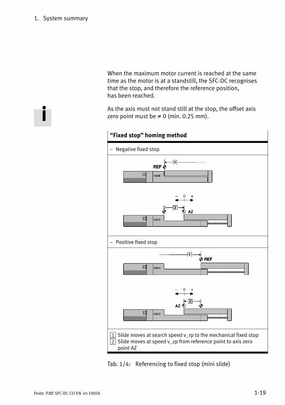
When the maximum motor current is reached at the sametime as the motor is at a standstill, the SFC−DC recognisesthat the stop, and therefore the reference position,has�been�reached.
As the axis must not stand still at the stop, the offset axiszero point must be � 0 (min. 0.25 mm).
�Fixed stop" homing method
� Negative fixed stop
AZ
� Positive fixed stop
AZ
1 Slide moves at search speed v_rp to the mechanical fixed stop2 Slide moves at speed v_zp from reference point to axis zero
point AZ
Tab.�1/4: Referencing to fixed stop (mini slide)
1. System summary
1−20 Festo P.BE−SFC−DC−CO−EN en 1005b
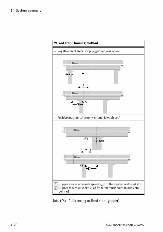
�Fixed stop" homing method
� Negative mechanical stop (= gripper jaws open)
AZ
� Positive mechanical stop (= gripper jaws closed)
AZ
1 Gripper moves at search speed v_rp to the mechanical fixed stop2 Gripper moves at speed v_zp from reference point to axis zero
point AZ
Tab.�1/5: Referencing to fixed stop (gripper)
1. System summary
1−21Festo P.BE−SFC−DC−CO−EN en 1005b
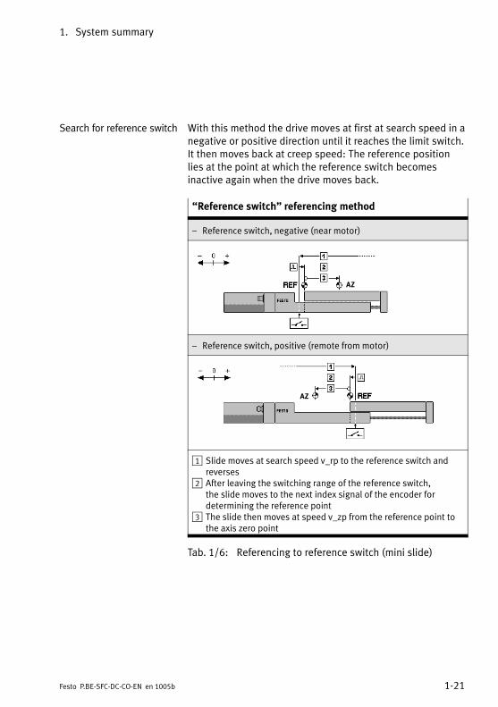
Search for reference switch With this method the drive moves at first at search speed in anegative or positive direction until it reaches the limit switch.It then moves back at creep speed: The reference positionlies at the point at which the reference switch becomesinactive again when the drive moves back.
�Reference switch" referencing method
� Reference switch, negative (near motor)
AZ
� Reference switch, positive (remote from motor)
AZ
1 Slide moves at search speed v_rp to the reference switch andreverses
2 After leaving the switching range of the reference switch,the�slide moves to the next index signal of the encoder fordetermining the reference point
3 The slide then moves at speed v_zp from the reference point tothe axis zero point
Tab.�1/6: Referencing to reference switch (mini slide)

1. System summary
1−22 Festo P.BE−SFC−DC−CO−EN en 1005b
�Reference switch" referencing method
� Reference switch, negative (anti−clockwise)
� Reference switch, positive (clockwise)
1 Rotary module moves at search speed v_rp to the referenceswitch and reverses
2 The rotary module then moves at speed v_zp from the referencepoint to the axis zero point
Tab.�1/7: Referencing to reference switch (rotary module)

1. System summary
1−23Festo P.BE−SFC−DC−CO−EN en 1005b
1.7 Fieldbus communication � FHPP and DS 402
1.7.1 Data exchange in CANopen
CANopen devices have an object directory which makes allimportant slave parameters accessible in a standardizedmanner. A CANopen system is essentially configured byaccessing the objects in the object directory of the individualstations. The data exchange in CANopen is in the form oftelegrams with which the work data is transmitted.A�distinction is made between Service Data Objects (SDO),which are used for transmitting service data from and to theobject directory, and between Process Data Objects (PDO),which serve for the fast transfer of current process states.In�addition, telegrams are defined for the networkmanagement and the fault messages.
SDO With SDOs you can access all entries in the Object Directory.The relevant Object Directory entries can be addressed withthe index and subindex of the entry. SDOs are used mainly fortransmitting acyclic data, e�g. for initializing during the bootprocedure. Within an SDO only one object can be accessed.A�reply is always sent to an SDO: A pair of CAN telegrams perobject are transmitted.
PDO PDOs are in principle a grouping of objects(variables�or�parameters) from the Object Directory.Maximum 8 bytes from different objects can be sent togetherin a PDO, i.e. the objects are mapped in the PDO.Process�Data Objects can be transmitted event−controlled,synchronous to a system pulse sequence or on demand.PDOs are transmitted by simple CAN messages and aresuitable for transmitting cyclic data.

1. System summary
1−24 Festo P.BE−SFC−DC−CO−EN en 1005b
1.7.2 Data profiles FHPP and DS 402
Festo has developed an optimised data profile,the��Festo�Handling and Positioning Profile (FHPP)" tailoredto handling and positioning tasks. For drives with a CANopen interface, the CANopen profileDS�402 for control by the master can also be used as analternative to the Festo profile. The DS�402 profile is thenalso the internally implemented profile; the FHPP interface ismapped by an implementation of DS�402.The�communications profile is in both cases DS 301.
Data profile Description
FHPP ControlControl is effected by way of the cyclic 8−byte control and statusdata; see chapter 5.5.2.ParametrisationParametrisation is carried out:� via a further 8 I/O bytes (Festo Parameter Channel FPC)� optionally via releant SDO accesses.For detailed information on the implemented objects seeappendix�B.1.1.
DS 402 ControlControl is effected as per device profile DS 402 with the followingvariations:� �Positioning profile" subprofile� status transfer 19 and 20, see appendix C.2.� Quick Stop active, state transition 12, see appendix C.2.ParametrisationParametrisation is effected via SDO accesses (DS�402).For detailed information on the implemented objects seeappendix�C.1.
Tab.�1/8: Control and parametrisation methods depending on data profile
The FHPP enables uniform control and programming for thevarious fieldbus systems and controllers from Festo.Parameter values, control and status bytes required duringoperation can be written and read via the Object Directoryand a structure description. Communication via the CANopenfield bus is made via 8 bytes of I/O data.

1. System summary
1−25Festo P.BE−SFC−DC−CO−EN en 1005b
The FHPP defines uniform operating modes and I/O datastructures for the user.
� Parameter access as per FHPP FPC(PDO�2;�optional:�SDO)
� Sequence control as per FHPP Standard (PDO 1) with theoperating modes Direct mode or Record Select.
Direct mode Positioning tasks in positioning or power operation can beexecuted as direct mode. The positioning task is transferreddirectly in the I/O telegram (FHPP standard). The mostimportant nominal values (position, velocity, force/torque...)are thereby transferred. Supplementary parameters aredetermined via the parametrisation (FHPP FPC).
Record Select Positioning tasks in positioning mode can be executed withRecord Select. The positioning data are set indirectly viapositioning sets which are taught via FCT, the control panel orfield bus and saved in the controller. 31 position sets can besaved in the SFC−DC. A record contains all the parameterswhich are specified for a positioning job. The record numberis transferred to the cyclic I/O data as the nominal or actualvalue (FHPP standard).
Detailed information on the FHPP can be found starting atchapter 5.5.

1. System summary
1−26 Festo P.BE−SFC−DC−CO−EN en 1005b
Direct mode1
2...
n
Record selection
PDO 1 (FHPP standard)
TxPDO 2 RxPDO 2
8 bytes I/O as per FHPP standard 8 bytes I/O as per FHPP FPC
PNU SI
CDIR.B1/B2*
Forcemode
Positioningmode
Positioningmode
CCON.B6/B7*
CPOS* (reference travel, teach, start...)
TxPDO 1 RxPDO 1
� ...� Parameter no. PNU� Subindex SI� Parameter value� ...
� *Control/status bytes� Record no.� ...
...−FHPP.EDS
100
Festo Handling und Positioning Profile (FHPP)
Parameter access
� ...� Object (Index)� Subindex SI� Parameter value� ...
� *Control/status bytes� Nominal/actual value 1, 2...� ...
Object SI
2064h
Sequence control
PNUhex + 2000h
...
1043
...
2413h
Object SI
2...
1000h
3...Acyclic data channel (optional)
Cyclic data channel
PDO 2 (FHPP−FPC)
TxSDO RxSDO
SD0
...
Fig.�1/6: Festo Handling and Positioning Profile (FHPP)

Fitting
2−1Festo P.BE−SFC−DC−CO−EN en 1005b
Chapter 2

2. Fitting
2−2 Festo P.BE−SFC−DC−CO−EN en 1005b
Contents
2.1 General Information 2−3 . . . . . . . . . . . . . . . . . . . . . . . . . . . . . . . . . . . . . . . . . . . . .
2.2 Dimensions of the controller 2−3 . . . . . . . . . . . . . . . . . . . . . . . . . . . . . . . . . . . . . .
2.3 Mounting the controller 2−4 . . . . . . . . . . . . . . . . . . . . . . . . . . . . . . . . . . . . . . . . . .
2.4 Notes on mounting electrical axes 2−6 . . . . . . . . . . . . . . . . . . . . . . . . . . . . . . . . .
2. Fitting
2−3Festo P.BE−SFC−DC−CO−EN en 1005b
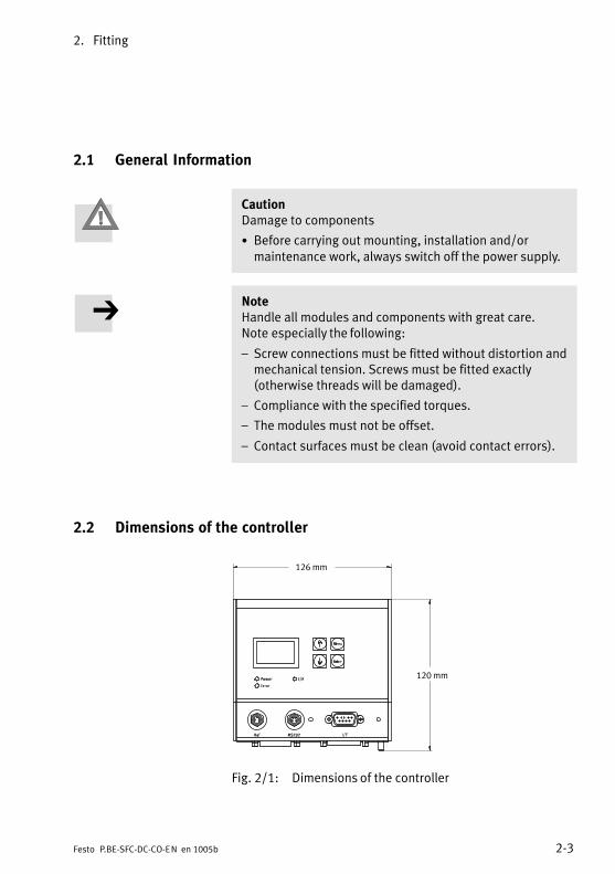
2.1 General Information
CautionDamage to components
· Before carrying out mounting, installation and/ormaintenance work, always switch off the power supply.
NoteHandle all modules and components with great care.Note�especially the following:
� Screw connections must be fitted without distortion andmechanical tension. Screws must be fitted exactly(otherwise threads will be damaged).
� Compliance with the specified torques.
� The modules must not be offset.
� Contact surfaces must be clean (avoid contact errors).
2.2 Dimensions of the controller
120 mm
126 mm
Fig.�2/1: Dimensions of the controller
2. Fitting
2−4 Festo P.BE−SFC−DC−CO−EN en 1005b
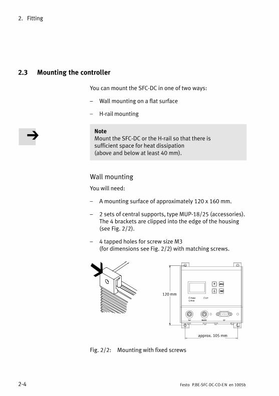
2.3 Mounting the controller
You can mount the SFC−DC in one of two ways:
� Wall mounting on a flat surface
� H−rail mounting
NoteMount the SFC−DC or the H−rail so that there issufficient�space for heat dissipation(above�and�below�at�least�40�mm).
Wall mounting
You will need:
� A mounting surface of approximately 120 x 160 mm.
� 2 sets of central supports, type MUP−18/25 (accessories).The 4 brackets are clipped into the edge of the housing(see Fig.�2/2).
� 4 tapped holes for screw size M3(for�dimensions�see�Fig.�2/2) with matching screws.
120 mm
approx. 105 mm
Fig.�2/2: Mounting with fixed screws

2. Fitting
2−5Festo P.BE−SFC−DC−CO−EN en 1005b
H−rail mounting
When mounting onto an H−rail, proceed as follows:
1. Make sure the mounting area is able to take the weight ofthe SFC−DC.
2. Mount an H−rail(DIN�mounting�rail�EN�60715�−�35x7.5�or�35x15).
With 35x7.5 H−rail only: Maintain a max. distance of3.3�mm between the housing web and the H−rail:
· If possible, use a part of the H−rail where there are nomounting screws.
· If you need to insert a screw underneath the SFC−DC:use e.g.�an M6 screw as per ISO−7380ULF.
3. Hang the SFC−DC on the H−rail as follows:
· First from below, pressing against the clampingelement, then
· swing upwards against the H−rail.
When you let go, the clamping element presses theSFC−DC into the groove at the top.
1 H−rail
2 Dovetail clamp
3 With 35x7.5 H−rail:gap between housingweb and H−rail:3.3�mm
1 2 3
Fig.�2/3: Mounting the SFC−DC onto an H−rail

2. Fitting
2−6 Festo P.BE−SFC−DC−CO−EN en 1005b
2.4 Notes on mounting electrical axes
Refer to the following documentation when mounting theelectric axis:
� Operating instructions for the electric drive used.
� Instructions for the components used.
WarningIf a drive is mounted in a sloping or vertical position,loads�may fall down and cause injury to persons.
· Check whether additional external safety measures arenecessary (e.g. toothed latches or moveable bolts)
This prevents the work load sliding down suddenly if thereis a power failure.
Make sure that:
· the drive is fitted securely and is correctly aligned,
· the working space in which the drive and effective loadwill move is of sufficient size for operation with a usefulload,
· the useful load does not collide with any axis componentwhen the slide moves to its end position.

Installation
3−1Festo P.BE−SFC−DC−CO−EN en 1005b
Chapter 3

3. Installation
3−2 Festo P.BE−SFC−DC−CO−EN en 1005b
Contents
3.1 Installation overview 3−3 . . . . . . . . . . . . . . . . . . . . . . . . . . . . . . . . . . . . . . . . . . . .
3.2 Power supply 3−6 . . . . . . . . . . . . . . . . . . . . . . . . . . . . . . . . . . . . . . . . . . . . . . . . . .
3.3 Earthing 3−9 . . . . . . . . . . . . . . . . . . . . . . . . . . . . . . . . . . . . . . . . . . . . . . . . . . . . . . .
3.4 Motor connection 3−10 . . . . . . . . . . . . . . . . . . . . . . . . . . . . . . . . . . . . . . . . . . . . . . .
3.5 Serial interface 3−11 . . . . . . . . . . . . . . . . . . . . . . . . . . . . . . . . . . . . . . . . . . . . . . . . .
3.6 Input for external reference switch 3−13 . . . . . . . . . . . . . . . . . . . . . . . . . . . . . . . . .
3.7 Control 3−15 . . . . . . . . . . . . . . . . . . . . . . . . . . . . . . . . . . . . . . . . . . . . . . . . . . . . . . .
3.8 Connecting the field bus 3−18 . . . . . . . . . . . . . . . . . . . . . . . . . . . . . . . . . . . . . . . . .
3.8.1 Fieldbus cable 3−18 . . . . . . . . . . . . . . . . . . . . . . . . . . . . . . . . . . . . . . . . . .
3.8.2 Fieldbus baud rate and Fieldbus length 3−19 . . . . . . . . . . . . . . . . . . . . . .
3.8.3 Information on connecting the fieldbus 3−20 . . . . . . . . . . . . . . . . . . . . . .
3.8.4 Connection with fieldbus plugs from Festo 3−22 . . . . . . . . . . . . . . . . . . .
3.8.5 Connection by other Sub−D plugs 3−26 . . . . . . . . . . . . . . . . . . . . . . . . . . .
3.9 Bus termination with terminating resistors 3−27 . . . . . . . . . . . . . . . . . . . . . . . . . .
3.9.1 Install a terminating resistor using the adapters 3−27 . . . . . . . . . . . . . . .

3. Installation
3−3Festo P.BE−SFC−DC−CO−EN en 1005b
3.1 Installation overview
WarningBefore carrying out mounting, installation and/ormaintenance work, always switch off the power supply.
In this way, you can avoid:
� uncontrolled movements of the connected actuators
� non−defined switching states of the electroniccomponents.
CautionFaulty pre−assembled lines may destroy the electronicsand trigger unexpected movements of the motor.
· Use only lines specified as accessories for theinstallation of the system (see Tab.�3/2). Only in this waycan you be sure that the system will work properly.
Note· Lay all flexible lines so that they are free of kinks andfree of mechanical stress; if necessary use an energychain.
· Comply with the specified maximum line lengths.

3. Installation
3−4 Festo P.BE−SFC−DC−CO−EN en 1005b
1 Control (CANopeninterface, I/F)
2 Earth terminal
3 Power supply (Power)
4 Motor connection (Motor)
5 Reference switch(Ref)
6 Serial interface(RS232)
1
2
3
4
5
6
Fig.�3/1: Connections of the SFC−DC
Connections on the SFC−DC Description
Controller/Fieldbus
For type SFC−DC−...−CO:� Sub−D 9−pin� Plug
Interface for connection toCANopen
Earthterminal
� Stud bolt, M4 Functional earthingconnection (optionally viapower supply cable)
Powersupply
� Sub−D 7W2� Plug
Voltage connection with2�high−current contactsand 5�low−current contacts(separate load and logicvoltage supply)
Motorconnection
� Sub−D 15−pin� Socket
Motor activation withencoder signals
Referenceswitch
� M8, 3−pin� Socket
Sensor input for referenceswitch
Serialinterface
� M8, 4−pin� Socket
RS232 interface forparametrising,commissioning anddiagnosing
Tab.�3/1: Overview of connections

3. Installation
3−5Festo P.BE−SFC−DC−CO−EN en 1005b
If unoccupied connectors are touched, there is a risk that ESD(electrostatic discharge) may cause damage to the SFC−DC orother system components. Place protective caps on unusedterminal connections in order to prevent such discharges.
The plug connectors on the Festo cables listed in thefollowing are designed to conform to protection class IP54when connectors are plugged in and secured, or when theconnections on the SFC−DC are fitted with caps.
Connection Cable/plug Type Length [m]
Power supply Power supply cable KPWR−MC−1−SUB−15HC−... 2,5 / 5 / 10
Motor connection Motor cable KMTR−DC−SUB−15−M12−... 2,5 / 5 / 10
Control Control line KES−MC−1−SUB−15−... 2,5 / 5 / 10
Reference switch e.g. type SMT−10... or extension cable type KM8−M8−...
CANopen interface Fieldbus plug for openfieldbus cable end
FBS−SUB−9−BU−2x5POL−B –
Fieldbus plug for M12adapter
FBA−2−M12−5POL –
Tab.�3/2: Overview of cables and plugs (accessories)
To ensure the IP protection class is complied with:
· Seal unused M8 connections with type ISK−M8 protectivecaps (accessories).
· Hand−tighten the union nuts/locking screws of the plugs.
IP20 protection is attained with the following Festo plugs:� Screw terminal adapter type FBA−1−SL−5−POL, � Field bus plug type FBS−SUB−9−WS−CO−K.
Observe the permissible tightening torques specified in thedocumentation for the lines and plugs used.

3. Installation
3−6 Festo P.BE−SFC−DC−CO−EN en 1005b
3.2 Power supply
Warning· Use only PELV circuits as per IEC/DIN EN 60204−1for�the�electric power supply (protective extra−low�voltage, PELV).Also observe the general requirements for PELV circuitsin accordance with IEC/DIN EN 60204−1.
· Use only power sources that guarantee reliableelectrical isolation of the operating voltage as perIEC/DIN EN 60204−1.
Protection against electric shock (protection against directand indirect contact) is guaranteed in accordance withIEC/DIN EN 60204−1 by using PELV circuits(electrical�equipment of machines, general requirements).
The internal power and controller electronics are suppliedwith DC voltage by way of the power supply connection.
NoteBe sure to keep to the voltage supply tolerances;see�Tab.�3/4. The tolerance must be maintained evendirectly at the power supply connection of the SFC−DC.
· For power supply, use only one of the following cablesfrom the Festo accessory list:
� Power supply cable KPWR−MC−1−SUB−15HC−...
� Cable length max. 10 m.
· Use a regulated power supply unit with
� at least 5 A peak current

3. Installation
3−7Festo P.BE−SFC−DC−CO−EN en 1005b
CautionDamage to the device.
The 24 VDC power supplies of the SFC−DC have no specialprotection against voltage overload.
· Make sure the permissible voltage tolerance is neverexceeded; see Tab.�3/4.
Connection Pin Designation Function Core colour 1)
A1 Load power +24 VDC load Black, 1
A2 Load power GND load 2) Black, 2
1 Logic powerVCC
+24VDC logic White
2 Logic powerGND
GND logic 2) Brown
3 n.c. Reserved Green
4 FE Earth terminal(housing) 3)
� 4)
5 n.c. Reserved Yellow
� Plug housing Earth terminal(housing) 3)
Earthing strapwith cable lugM4
FE Earth terminal(housing) 3)
�
1) Wire colours with power supply cable of type KPWR−MC−1−SUB−15HC−...2) The GND terminals of the power supplies must not be connected to the housing, screen or
functional earth (FE)!3) Functional earth; use only one terminal; see chapter 3.34) With cables of type KPWR−MC−1−SUB−15HC−... not connected.
Tab.�3/3: �Power" connection on SFC−DC

3. Installation
3−8 Festo P.BE−SFC−DC−CO−EN en 1005b
The power supply must meet the following requirements:
Power supply Value
Load supply (pin A1, A2)� Nominal current� Peak current� Internal fuse
24 VDC ± 10 %3 A ± 30 %5 A ± 30 %7 A very quick acting
Logic supply (pin 1, 2)� Nominal current� Peak current� Internal fuse
24 VDC ± 10 %0.1 A ± 30 %0.8 A ± 30 %2 A slow−blow
Tab.�3/4: Power supply specification
1 2 3 4A1 5 A2
1 2 3
1 Potential equalisation is essential!
2 External fuses (optional, to protect the internal fuses)
3 Earth connection (optional, see chapter 3.3)
Fig.�3/2: Power supply connection example

3. Installation
3−9Festo P.BE−SFC−DC−CO−EN en 1005b
3.3 Earthing
Note· Connect one of the earth terminals of the SFC−DC at lowimpedance (short cable with wide cross−section) to theearth potential.
You can thereby avoid interference from electromagneticsources and ensure electromagnetic compatibility inaccordance with EMC directives.
To connect the SFC−DC to the earth potential use one of thefollowing earthing connections:
� Earthing strap on free end of the power supply cable;see�assembly instructions for cable typeKPWR−MC−1−SUB−15HC−..., or
� earth connection on the housing of the SFC−DC,see�Tab.�3/3.
CautionDamage to the device
Never connect one of the power supply connections(Tab.�3/3, pin 1, 2, A1, A2) to FE or to the housing.This�will�avoid damaging the device and impairingprotection against electromagnetic interference (EMC).
NoteNote that only one of the two earthing connections can beused at any one time (so as to avoid earth loops).
When using the earth terminal on the SFC−DC housing:
· Use a suitable earthing cable with an M4 cable lugtogether with the accompanying nut and toothed washer.
· Tighten the nut with max. 1.7 Nm.

3. Installation
3−10 Festo P.BE−SFC−DC−CO−EN en 1005b
3.4 Motor connection
By way of the motor connection the motor of the connectedSLTE is activated and the encoder signals are transmitted.
NoteTo connect the SLTE use only one of the following cablesfrom the Festo accessory list:
� motor cable KMTR−DC−SUB−15−M12−...
� max length 10 m.
Connection Pin Designation Function
1 +5VDC VCC logic
8 1 2 O Encoder channel A (RS485)
3 A/ Encoder channel A/
15 94 B Encoder channel B (RS485)
5 B/ Encoder channel B/
6 C Encoder channel C (RS485)
7 C/ Encoder channel C/
8 GND logic GND logic
9 GND GND
10 GND GND
11 GND GND
12 Motor + Motor +
13 Motor − Motor −
14 GND GND
15 GND GND
� Plug housing Cable shield
Tab.�3/5: �Motor" connection on the SFC−DC

3. Installation
3−11Festo P.BE−SFC−DC−CO−EN en 1005b
3.5 Serial interface
Serial interface for parametrising, commissioning anddiagnosing.
NoteTo connect a PC to the SFC−DC, use exclusively one of thefollowing cables from the Festo accessories list:
� programming cable KDI−MC−M8−SUB−9−...
� length 2.5 m.
· Remove the cap from the serial port on the SFC−DC,if�fitted.
· Connect the following terminals with the programmingcable:
� the connection socket on the SFC−DC
� a serial interface COMx on the PC
M8 socket Description
3 4 2 1 1 GND Ground
2 RXD RS232 receiving line of the PC 1)
3 TXD RS232 transmission line ofthe�PC�1)
4 −−− Reserved for servicing personnel� do not connect!
1) The levels correspond to the RS232 standard
Tab.�3/6: �RS232" connection (serial interface)
3. Installation
3−12 Festo P.BE−SFC−DC−CO−EN en 1005b
Information on commissioning and parametrising the SFC−DCvia the serial interface can be found in chapter 5.3.2 and inthe help system for the Festo Configuration Tool softwarepackage. You will find information on transmitting CI commands via theserial interface in appendix C.1.
NoteThe RS232 interface is not electrically isolated.It�is�not�suitable for permanent connection to PC systems,nor for use as a control interface.
· Use this terminal only for commissioning.
· Remove the programming cable in continuousoperation.
· Close off the port with the supplied cap (type ISK−M8),

3. Installation
3−13Festo P.BE−SFC−DC−CO−EN en 1005b
3.6 Input for external reference switch
If you are not using a reference switch:
· Seal the terminal with the protective cap supplied(type�ISK−M8).
Use the following Festo proximity sensors for example:
� Electric proximity switch type SMT−10F−...(mountable�in�sensor bays on the drive unit).
Use an extension cable type KM8−M8−... as necessary.
To connect the reference switch:
· For the reference switch use the correct switch type(N.O.�= normally open), in PNP design.
· For connecting the reference switch use a cable withrotating thread sleeve on the end, e.g.�type SMT−10F... orextension cable type KM8−M8−...
· When selecting the sensor, note that the accuracy of thesensor switching point may affect the accuracy of thereference point.
· During installation, observe the position of the sensorrelative to the index pulse; shift the sensor if necessary(see warning �INDEX PULSE WARNING", chapter 6.3).

3. Installation
3−14 Festo P.BE−SFC−DC−CO−EN en 1005b
The power supply for the reference switch (24 V DC / Ground)is provided via pin 1/3.
CautionDamage to the device.
The 24 V DC voltage at pin 1 does not have any specialprotection against overload; the voltage is taken from themain supply with protection against ESD and incorrectpolarity.
· Use the terminal only for the reference switch(sensor�supply).
Use of this connection as a power supply for other devicesis not permitted.
The input for sensor signal REF complies in its electricalfeatures with the input specification in the appendix�Technical specifications".
M8 socket Description
143 1 +24VDC +24 VDC voltage output forreference switch
4 K Reference switch contact
3 GND Ground
Tab.�3/7: �Ref" (reference switch) connection on SFC−DC
3. Installation
3−15Festo P.BE−SFC−DC−CO−EN en 1005b
3.7 Control
Communication with the higher−level control is routed via thecontrol connection of the SFC−DC−...−CO.
To connect to the fieldbus there is a 9−pin Sub−D plug on theSFC−DC. This connection is used for the incoming andcontinuing field bus cables.
NoteOnly fieldbus plugs of type FBS−SUB−9−BU−2x5−POL−B orFBA−2−M12−5POL from Festo ensure conformance to IP54.
Note the instructions in chapter 3.8.5 if other sub−D plugsare used.

3. Installation
3−16 Festo P.BE−SFC−DC−CO−EN en 1005b
Connection Pin Designation Function Field busplug 1)
1 5 1 n.c. Not connected �
2 CAN_L CAN bus low A/L
6 9 3 CAN GND CAN bus reference potential GND
4 n.c. Not connected �
5 CAN_SHLD Screening, capacitive connectionto housing
Clampingstrap
6 2) Logic power GND Do not connect(connected�with�Powerconnection, refer to Tab.�3/3)
�
CAN_V� Bus interface voltage supplyreference potential
7 CAN_H CAN bus high B/H
8 n.c. Not connected �
9 2) n.c. Not connected V+
CAN_V+ Power supply to the bus interface
� Screening/housing
Connection to functional earth Clampingstrap
1) Pin assignment on field bus plug type FBS−SUB−9−BU−2x5−POL−B from Festo2) Depending on parameterisation �CAN Voltage Supply" (see chapter 5.2.8) or [CAN Volt.Supply] on
control panel (see chapter 4.5, [CAN parameter] ):� Internal supply (default):
CAN bus (pins 2, 3, 7) referred to logic voltage supply of SFC−DC. · Don not connect pins 6 and 9.
� External supply: CAN bus (pins 2, 3, 7) related to external logic voltage supply. (enables electrically isolated bus connection). · Pins 6 and 9 must be supplied with 24 Volts.
Tab.�3/8: �I/F" port (control connection) on SFC−DC−...−CO

3. Installation
3−17Festo P.BE−SFC−DC−CO−EN en 1005b
NoteThe screen connection at pin 5 of the field bus interface iscapacitively connected internally to the housing.This�prevents compensating currents from flowing via thescreening of the fieldbus cable (see Fig.�3/3).
1 Capacitiveconnection
2 Housing
51
96
1
2
Fig.�3/3: Screen connection inside the SFC−DC
3. Installation
3−18 Festo P.BE−SFC−DC−CO−EN en 1005b
3.8 Connecting the field bus
3.8.1 Fieldbus cable
NoteIn case of faulty installation or high transmission rates,data transmission errors can occur as a result of signalreflections and attenuations.Transmission errors can be caused by:
� missing or incorrect terminating resistor
� incorrect screened connection
� branches
� transmission over long distances.
� inappropriate cables.
Observe the cable specifications. For information on thecable type refer to the manual for your controller or to CIAspecification DS 102.
NoteIf the SFC−DC is fitted onto the moving part of a machine,the Fieldbus cable on the moving part must be providedwith strain relief. Also observe the relevant regulations inEN�60204 part 1.
Use a twisted−pair screened 4−wire cable as the field buscable.
When using a Festo field bus a cable diameterof�5�...�8�or�7�...�10 mm is permitted.

3. Installation
3−19Festo P.BE−SFC−DC−CO−EN en 1005b
3.8.2 Fieldbus baud rate and Fieldbus length
The maximum permissible fieldbus length and length of thebranch lines depends on the baud rate used. You will finddetailed information in the manuals for your control systemor bus interface, or in CIA specification DS 102.
Note· Refer to the manuals for your control system or businterface in order to ascertain which T−adapter andmaximum branch line length are permitted for yourcontroller.
· Also take into account the sum of the branch line lengthswhen calculating the maximum permitted length of thefieldbus cable.

3. Installation
3−20 Festo P.BE−SFC−DC−CO−EN en 1005b
3.8.3 Information on connecting the fieldbus
Bus supply Avoid excessively long distances between the businterface/logic supply and the SFC−DC.
Caution· When connecting the field bus interface and the powersupply for the bus interface pay attention to the polarity.
· Connect the screen.
· With external voltage supply (see Tab.�3/8): Protect the voltage supply to the bus interfaceexternally, according to the number of stations on thebus.
NoteBus slaves have different tolerances in respect of theinterface supply, depending on the manufacturer.Observe�this when planning the bus length and placing thepower supply unit.
For the SFC−DC the following tolerance applies to the businterface supply (pin 9 on the Sub−D plug): Vmax = 30.0 VVmin = 11.0 V
Recommendation:Place the power supply unit approximately at the centre ofthe bus.

3. Installation
3−21Festo P.BE−SFC−DC−CO−EN en 1005b
With the Festo fieldbus plug you can implement a T−adapter(see diagram).
Ö
2 31
4
5
6
1 Fieldbus
2 Power supply
3 Screening
4 T−adapter (T−tap)
5 Branch line
6 Field bus plug with T−adapter function
Fig.�3/4: Layout of the bus interface and example of connection

3. Installation
3−22 Festo P.BE−SFC−DC−CO−EN en 1005b
3.8.4 Connection with fieldbus plugs from Festo
Connection with Festo field bus plugs (IP54)
· Observe the fitting instructions for the field bus plug.Tighten the two fastening screws at first by hand and thenwith max. 0.4 Nm.
With Festo fieldbus plugs type FBA−2−M12−5POL orFBS−SUB−9−BU−2x5POL−B, you can connect the SFC−DC to thefieldbus in a user−friendly manner. You can disconnect theplug from the SFC−DC without breaking the bus connection(T−tap function).
NoteThe clamp strap in the fieldbus plug from Festo isconnected internally only capacitively with the metallichousing of the Sub−D plug. This is to prevent equalisingcurrents flowing through the screening of the Fieldbuscable.
· Clamp the screen of the fieldbus cable under the clampstrap in the fieldbus plug. The �SLD" terminal in the fieldbus plug is optional.

3. Installation
3−23Festo P.BE−SFC−DC−CO−EN en 1005b
1 Folding coverwith inspectionwindow
2 Clamp strap forscreenconnection
3 Blanking plug ifconnectionunused
4 Field buscontinuing (OUT)
5 Field busincoming (IN)
6 Only capacitivelyconnected
V+
GND H L
SLD
V+
GND H L
SLD
21 3
456
Bus in
Bus out
Fig.�3/5: Festo fieldbus plug type FBS−SUB−9−BU−2x5POL−B

3. Installation
3−24 Festo P.BE−SFC−DC−CO−EN en 1005b
M12 adapter (IP54)
Order this adapter from Festo (type: FBA−2−M12−5POL).The�bus is connected to a 5−pin M12 socket with a PG 9fitting. Use the second connection socket for the continuationof the Fieldbus.
Note· Use protective caps or blanking plugs to seal unusedconnections.
You will then comply with protection class IP65.
Order this adapter from Festo (type: FBA−2−M12−5POL).
M12 adapter Pin no.
5
2
3
4
15
1
4
3
2 1. Screening2. 24 VDC bus3. 0 V bus4. CAN_H5. CAN_L
Protective cap or plug with bustermination resistor ifconnection is not used.
Bus inBus out
Tab.�3/9: Pin assignment of fieldbus interface (adapter for 5−pin M12 connection)
With the two M12 adapters you can implement a T−adapter(see Fig.�3/4).

3. Installation
3−25Festo P.BE−SFC−DC−CO−EN en 1005b
Screw terminal adapter (IP20)
With this adapter the bus is connected to a 2 x 5−pin terminalstrip. Use the second row of connections for the continuingfield bus.The maximum permitted current at the terminals is 4 A.Use�cables with a cross sectional area of min. 0.34 mm2.
Order this adapter from Festo (type: FBA−1−SL−5POL) togetherwith terminal strip type FBSD−KL−2x5POL.
Screw terminaladapter
Pin no.
1 2 3 4 5
1. 0 V bus2. CAN_L3. Screening4. CAN_H5. 24 VDC bus
2 x 5−pin terminal strip
Tab.�3/10: Pin assignment of field bus interface(5−pin�screw�terminal adapter)
If you connect the field bus via the terminal strip typeFBSD−KL−2x5POL from Festo, you can implement a T−adapterfunction.
Alternatively, pre−assembled bus cables from variousmanufacturers are also available(see�also�appendix�A,�Accessories).

3. Installation
3−26 Festo P.BE−SFC−DC−CO−EN en 1005b
3.8.5 Connection by other Sub−D plugs
If you are using the Festo type FBS−SUB−9−WS−CO−K plug orSub−D plugs from other manufacturers, you must replace thetwo flat screws by which the fieldbus plug is fitted in theSFC−DC by a bolt of type UNC 4−40/M3x5 (supplied).
NoteIf both screws or stud bolts are removed simultaneously,there is a risk that the plug may be pressed into theSFC−DC housing with the internal circuit board.
· Always leave one of the screws or stud bolts fitted whilechanging over.
Proceed as follows:
1. First slacken just one of the mounting screws andremove�it.
2. Screw one of the mounting bolts into the vacant tappedhole and tighten it.Maximum tightening torque: 0.48 Nm
3. Repeat steps 1 and 2 for the other screw.
NoteNote that when using Sub−D plugs from othermanufacturers only IP20 protection is attained.

3. Installation
3−27Festo P.BE−SFC−DC−CO−EN en 1005b
3.9 Bus termination with terminating resistors
NoteIf the SFC−DC is at the beginning or end of the Fieldbussegment, a bus termination will be required.
· Always use a bus termination at both ends of thefieldbus.
If you are using T−adapters, install the terminating resistor atthe unused output of the T−adapter.
Recommendation:For bus termination, fit a resistor (120 �, 0.25 W,see�following diagram) in the Festo fieldbus plug.
1 Protective cap
2 Resistor for bustermination(120��, 0.25 W)
V+
GND H L
SLD
V+
GND H L
SLD
V+
GND H L
SLD
1 2
Fig.�3/6: Bus termination with resistor in Festo fieldbus plug
3.9.1 Install a terminating resistor using the adapters
If the SFC−DC you are connecting to is at the end of a fieldbus,install a terminating resistor (120 �, 0.25 W) in the fieldbussocket:
· Connect the terminating resistor between the cores forCAN_H and CAN_L.


The control panel (only type SFC−DC−...−H2−...)
4−1Festo P.BE−SFC−DC−CO−EN en 1005b
Chapter 4

4. The control panel (only type SFC−DC−...−H2−...)
4−2 Festo P.BE−SFC−DC−CO−EN en 1005b
Contents
4.1 Design and function of the control panel 4−4 . . . . . . . . . . . . . . . . . . . . . . . . . . . .
4.2 The menu system 4−6 . . . . . . . . . . . . . . . . . . . . . . . . . . . . . . . . . . . . . . . . . . . . . . .
4.2.1 Accessing the main menu 4−6 . . . . . . . . . . . . . . . . . . . . . . . . . . . . . . . . .
4.2.2 Selection of a menu command 4−6 . . . . . . . . . . . . . . . . . . . . . . . . . . . . .
4.2.3 Enable device control [HMI control] 4−8 . . . . . . . . . . . . . . . . . . . . . . . . .
4.3 [Diagnostic] menu 4−9 . . . . . . . . . . . . . . . . . . . . . . . . . . . . . . . . . . . . . . . . . . . . . .
4.4 [Positioning] menu 4−13 . . . . . . . . . . . . . . . . . . . . . . . . . . . . . . . . . . . . . . . . . . . . . .
4.4.1 Reference travel [Positioning] [Homing]. 4−14 . . . . . . . . . . . . . . . . . . . . .
4.4.2 Positioning records [Positioning] [Move posit. set] / [Demo posit. tab] 4−15 . . . . . . . . . . . . . . . . . . . . . . . . . . . . . . . . . . . . . . . .
4.5 [Settings] menu 4−17 . . . . . . . . . . . . . . . . . . . . . . . . . . . . . . . . . . . . . . . . . . . . . . . .
4.5.1 Axis type [Settings] [Axis type] 4−17 . . . . . . . . . . . . . . . . . . . . . . . . . . . . .
4.5.2 Axis parameter [Settings] [Axis parameter] 4−20 . . . . . . . . . . . . . . . . . . .
4.5.3 Reference travel parameter [Settings] [Homing paramet.] 4−21 . . . . . . .
4.5.4 Positioning record table [Settings] [Position set] 4−22 . . . . . . . . . . . . . . .
4.5.5 Password [Settings] [Password edit] 4−23 . . . . . . . . . . . . . . . . . . . . . . . .
4.5.6 Bus parameter [Settings] [CAN parameter] 4−26 . . . . . . . . . . . . . . . . . . .

4. The control panel (only type SFC−DC−...−H2−...)
4−3Festo P.BE−SFC−DC−CO−EN en 1005b
Motor controller type SFC−DC−...−H2−... offers on the controlpanel all functions necessary for commissioning,programming and diagnosing. An overview of the button and menu functions can be foundin this chapter. Commissioning with the control panel isdescribed starting from chapter 5.2.
With the SFC−DC−...H0−... (without control panel) you can carryout commissioning of the SFC−DC via the RS232 interface withthe Festo Configuration Tool. Instructions on this can befound in chapter 5.3.2.
CautionErrors may occur if you attempt to access control andoperating functions via the FCT and the control panel at thesame time.
· Make sure that the FCT, the control panel and the controlinterface of the SFC−DC are not used at the same time.
· If necessary, use the possibility of blockingparametrisation and positioning functions via the controlpanel (HMI access, see chapter 5.5.2)
NoteIf applicable, remove any protective foil on the displaybefore commissioning.
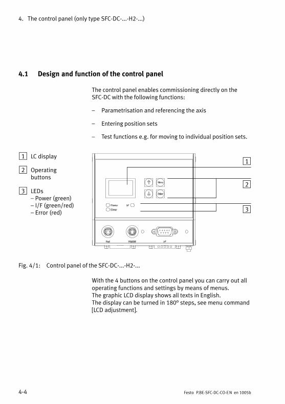
4. The control panel (only type SFC−DC−...−H2−...)
4−4 Festo P.BE−SFC−DC−CO−EN en 1005b
4.1 Design and function of the control panel
The control panel enables commissioning directly on theSFC−DC with the following functions:
� Parametrisation and referencing the axis
� Entering position sets
� Test functions e.g.�for moving to individual position sets.
1 LC display
2 Operatingbuttons
3 LEDs� Power (green)� I/F (green/red)� Error (red)
1
2
3
Fig.�4/1: Control panel of the SFC−DC−...−H2−...
With the 4 buttons on the control panel you can carry out alloperating functions and settings by means of menus.The�graphic LCD display shows all texts in English.The�display�can be turned in 180° steps, see menu command[LCD�adjustment].

4. The control panel (only type SFC−DC−...−H2−...)
4−5Festo P.BE−SFC−DC−CO−EN en 1005b
The visual display of the operating states is shown via 3 LEDs(see also chapter 6.2).
� Power: Indicates ready status
� I/F: Bus status, positioning status
� Error: Error
Function Key
MENU Activated by the status display from themain menu Menu
ESC Rejects the current entry and switchesback step by step to the higher−ordermenu level or status display
EMERG.STOP Interrupts the current positioningprocedure (> Error mode; confirm with<Enter>, then automatic return to thestatus display)
OK Confirms the current selection or entryEnter
SAVE... Saves parameter settings permanentlyin the EEPROM
Enter
START/STOP Starts or stops a positioning procedure(only in Demo mode). After stop:Display of current position; use <Menu>to return to the higher−order menulevel.
{ } Scrolls within a menu level in order toselect a menu command v
EDIT Sets parameters V
Tab.�4/1: Button function (overview)
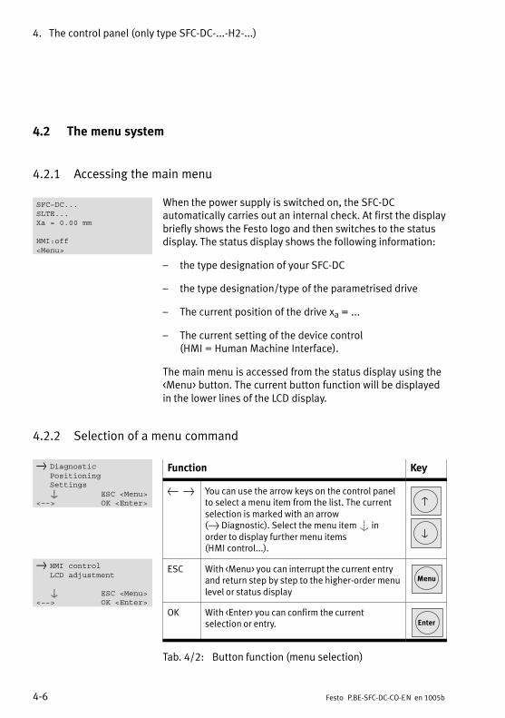
4. The control panel (only type SFC−DC−...−H2−...)
4−6 Festo P.BE−SFC−DC−CO−EN en 1005b
4.2 The menu system
4.2.1 Accessing the main menu
When the power supply is switched on, the SFC−DCautomatically carries out an internal check. At first the displaybriefly shows the Festo logo and then switches to the statusdisplay. The status display shows the following information:
� the type designation of your SFC−DC
� the type designation/type of the parametrised drive
� The current position of the drive xa = ...
� The current setting of the device control (HMI = Human Machine Interface).
The main menu is accessed from the status display using the<Menu> button. The current button function will be displayedin the lower lines of the LCD display.
4.2.2 Selection of a menu command
Function Key
{ } You can use the arrow keys on the control panelto select a menu item from the list. The currentselection is marked with an arrow(}�Diagnostic). Select the menu item S inorder to display further menu items(HMI�control...).
v
V
ESC With <Menu> you can interrupt the current entryand return step by step to the higher−order menulevel or status display
Menu
OK With <Enter> you can confirm the currentselection or entry. Enter
Tab.�4/2: Button function (menu selection)
SFC−DC...SLTE...Xa = 0.00 mm
HMI:off<Menu>
} DiagnosticPositioningSettingsS ESC <Menu>
<−−> OK <Enter>
} HMI controlLCD adjustment
S ESC <Menu><−−> OK <Enter>

4. The control panel (only type SFC−DC−...−H2−...)
4−7Festo P.BE−SFC−DC−CO−EN en 1005b
Menu command Description
} Diagnostic Displays the system data and the currently effective settings (see chapter 4.3)
} Pos. set table Displays the position set table
} Axis parameters Displays axis parameters and data
} System paramet. Displays system parameters and data
} CAN−BUS Diag Displays status and diagnostic information on the bus communication
} SW information Displays the operating system version (firmware)
} Positioning 1) 2) Homing and positioning runs for testing the position records (see chapter 4.4)
} Homing Starts reference run 1)
} Move posit. set Start positioning run �Position set"
} Demo posit. tab Start positioning run �Position set table"
} Settings 1) 2) Select the drive, parametrisation, programming the position sets, etc. (see chapter 4.5)
} Axis type } Festo} Sommer
Selection of the manufacturer. Subsequently, selection of the axis,see chapter 4.5.
} Axis parameter } Zero point 3) Offset axis zero point} p
} SW−limit−neg 3) Stroke limitation: Software end position, negative
} SW−limit−pos 3) Stroke limitation: Software end position, positive
} SAVE... Saves parameters to the EEPROM
} Homing paramet. } Homing method Select referencing method (stop, reference switch, etc.)} g p
} Velocity v_rp Positioning speed for searching for the reference point
} Velocity v_zp Positioning speed for moving to the axis zero point
} SAVE... Saves parameters to the EEPROM
} Position set } Position no. Number of the positioning record (1 ... 31)}
} Pos set mode Set status: Absolute or relative positioning
} Position 3) Target position of the position set
} Velocity Positioning speed of the position set
} Acceleration Start acceleration of the position set
} Deceleration Deceleration of the position set
} SAVE... Saves parameters to the EEPROM
} Password edit Set up a local password with 3 digits for the control panel (see chapter 4.5).
} CAN parameter Set the CANopen parameters
} HMI control 1) Presetting the device control via the control panel (see chapter 4.2.3)
} LCD adjustment Rotate the display in steps of 180°
1) If necessary password protection2) Control interface must be deactivated, see [HMI control]: HMI=on3) Teach mode
Tab.�4/3: Menu commands

4. The control panel (only type SFC−DC−...−H2−...)
4−8 Festo P.BE−SFC−DC−CO−EN en 1005b
4.2.3 Enable device control [HMI control]
To select the menu commands [Positioning] and [Settings],the �HMI: on" setting is required. Only then is the SFC−DCready to process user entries on the control panel.
When selecting the menu commands, you are requested tomodify the HMI setting.
[HMI control] You can also modify the setting directly with the [HMI control]menu command.
HMI 1) Device control
on The device is controlled manually via the control panel.The control interface of the SFC−DC is deactivated andControl Enable is set. The actual status of the FHPPcontrol bytes or the transmitted DS 402 control word isthen without effect.With active control via the control panel the drive cannotbe stopped with the STOP bit.
off Device control is carried out via the control interface ofthe SFC−DC.
1) Human Machine Interface
Tab.�4/4: States [HMI control]
The device control �HMI Control" can be blocked via thefieldbus:
� FHPP: Bit CCON.B5, �HMI Access locked" (see also HMI Access, chapter 5.5.2).
� DS 402: Control word bit 14.
HMI control[on/off] off?HMIAccessFree
ESC <Menu>EDIT <−> OK <Enter>

4. The control panel (only type SFC−DC−...−H2−...)
4−9Festo P.BE−SFC−DC−CO−EN en 1005b
4.3 [Diagnostic] menu
Displays the system data and the settings currently in effect.
1. Use the arrow keys in the main menu to select[Diagnostic] and press the <Enter> button.
2. Select one of the following menu commands:
� Position record table [Pos. set table]
� Axis parameters [Axis parameter]
� System parameters [System paramet.]
� Status and diagnostic information relating to buscommunication [CAN−BUS Diag]
� Version of the firmware of the SFC−DC e.g.�V4.02 [SW information]
Function Key
{ } You can scroll through the diagno�stic data with the arrow keys v V
ESC With <Menu> you can return to thehigher−order menu level Menu
Tab.�4/5: Button function [Diagnostic] menu
} Diagnostic
} Pos. set tableAxis parameterSystem paramet.CAN−BUS DiagSW information

4. The control panel (only type SFC−DC−...−H2−...)
4−10 Festo P.BE−SFC−DC−CO−EN en 1005b
[Pos. set table] Menu command for displaying the entries in the position settable.
When the menu command is accessed a table of position setswill be displayed. Select a position set and press the <Enter>button in order to display details of this position set.
[Pos. set table] Description
No. Number of positioning set (1 ... 31)
a/r Absolute (a) or relative (r) positioning
Pos Target position
Vel Travel speed
Acc Start acceleration (acceleration ramp)
Dec Deceleration (braking ramp)
Tab.�4/6: Elements [Pos. set table]
[Axis parameter] Menu command for displaying the following axis parametersand data:
[Axis parameter] Description
Vmax Maximum speed of travel
Xneg Stroke limitation: software end position,negative
Xpos Stroke limitation: Software end position,positive
Xzp Axis zero point offset
Feed Feed constant (e.g.�thread pitch)
Tab.�4/7: Elements [Axis parameter]
N a/r Pos Vel} 1 a 0.00mm 20.00mm/s
2 r 10.00mm 1.50mm/s3 a −5.00mm 5.00mm/s
...

4. The control panel (only type SFC−DC−...−H2−...)
4−11Festo P.BE−SFC−DC−CO−EN en 1005b
[System paramet.] Menu command for displaying the following systemparameters and data:
[System paramet.] Description
VRef [V] Internal reference voltage
VDig [V] Digital voltage
Imax [A] Maximum possible motor current(e.g.�power limitation / motor protection)
Iact [A] Current motor current
Temp [°C] Operating temperature, power end stage
Cycle Number of positioning cycles
Ref on/off Signal at reference switch input
Mode mm / ° System of measurement units(millimetres or degrees)
Hom.meth. � bl.pos� bl.neg� sw.pos� sw.neg
Fixed stop in positive directionFixed stop in negative directionReference switch in positive directionReference switch in neg. direction
Gear e.g.�4.38 Gear ratio of the drive
Tab.�4/8: Elements [System paramet.]

4. The control panel (only type SFC−DC−...−H2−...)
4−12 Festo P.BE−SFC−DC−CO−EN en 1005b
[CAN−BUS−Diag] Menu command to view status and diagnostic informationrelating to bus communication:
[CAN−BUS−Diag] Description
CANopen−BUS diagnosis (first line):
� Guarding Error 1) �Node guarding" activated (if enabled inmaster), e.g. master shut down or cablebreak.
� CAN WarningLimit 1) Telegrams not being received or cannot besent (no acknowledgement at lowest CANlevel), e.g. no bus connection.
� CO State stopped �Stop" network management commandreceived.
� CO State pre−op Pre−operational, normal state afterpower−on before the master transmits�Start node operational".
� State operational �Start node operational" transmitted bymaster, normal operating state.
1) The �Guarding Error" and �CAN WarningLimit" state displays areprioritized (regardless of the other states).
Baud rate Pre−set baud rate of SFC−DC:Values:1000k (1 MBaud), 800k, 500k, 800k, 125k,100k, 50k, 20k (20 kBaud)
Profiles Pre−set data profile.Controller/device profile with whichcommunication between the CAN masterand the SFC−DC is handled.� FHPP: The SFC−DC is controlled as per
the Festo Handling and PositioningProfile.
� DS 402: The SFC−DC is controlled inaccordance with DS 402.
CAN node ID CAN address of SFC−DC (hexadecimal/decimal).
Volt.Supply int./ext. CAN interface voltage supplyinternal/external
Tab.�4/9: [CAN−BUS−Diag] items

4. The control panel (only type SFC−DC−...−H2−...)
4−13Festo P.BE−SFC−DC−CO−EN en 1005b
4.4 [Positioning] menu
Starting a reference run or a positioning run to test theposition records.
Note· Before starting homing, make sure that:
� the positioning system is set up completely,wired�and supplied with power.
� The parametrisation is completed.
· Do not start a positioning run until the reference systemhas been defined by means of homing.
WarningDanger of injury.
With all positioning procedures the motor turns or theconnected axis starts to move.
· Make sure that nobody can reach into the positioningrange of the moveable load and that there are no objectsin its path.
NotePlease note that position records with speed v = 0 orinvalid target positions (−> error �TARGET POSITION OUT OFLIMIT") cannot be executed.

4. The control panel (only type SFC−DC−...−H2−...)
4−14 Festo P.BE−SFC−DC−CO−EN en 1005b
4.4.1 Reference travel [Positioning] [Homing].
1. Use the arrow keys to select [Positioning] from the mainmenu and press the <Enter>button.
2. Select the menu command:
� Reference run [Homing]
[Positioning] Description Note
[Homing] Homing for determining the mechani�cal reference system
First set the parameter in the menu[Settings] [Homing parameter].Factory setting: Referencing to stopin negative direction.
Tab.�4/10: Menu command [Homing]
3. Make sure that nobody can place his/her hand in thepositioning range of the moveable mass and that thereare no objects in its path. Start the homing run with START <Enter>
The following information is displayed:
� The search speed to the reference point v_rp,
� The travel speed v_zp to the axis zero point
Function
STOP With <Menu> you can abort the homing run; thisautomatically returns you to the status display. Menu
Tab.�4/11: Button function [Homing]
} Positioning
} HomingMove posit. setDemo posit. tab
HomingAttention!Motor moves...
ESC <Menu>START <Enter>
HOMINGv_rp = 10.0 mm/sv_zp = 5.0 mm/s
STOP<Menu>

4. The control panel (only type SFC−DC−...−H2−...)
4−15Festo P.BE−SFC−DC−CO−EN en 1005b
4.4.2 Positioning records [Positioning] [Move posit. set] / [Demo posit. tab]
NoteDo not start a positioning run until the reference systemhas been defined by means of a reference run.
For testing a particular positioning record in the positioningrecord table.
1. Use the arrow keys to select [Positioning] from the mainmenu and press the <Enter>button.
2. Select the menu command:
� Positioning run �Position record" [Move posit. set] � or
� Positioning run �Position record table"[Demo�posit.�tab]
[Positioning] Description Note
[Move posit. set] Positioning run for testing aparticular position record in theposition record table.
Parametrisation and referencingmust have been completed.
[Demo posit. tab] Positioning run (continuous loop) fortesting all position records (1 ... 31)in the position record table.
Parametrisation and referencingmust have been completed.There must be at least two positionsets in the memory.
Tab.�4/12: Elements [Positioning]
In the [Demo posit tab] positioning run, all position records1�...�31 in the position record table will be executed one afterthe other. If the position set table contains a position set withspeed v = 0, this position set and all the following sets willnot be processed; the positioning run will be continued withposition set 1.
} Positioning
Homing} Move posit. set
Demo posit. tab

4. The control panel (only type SFC−DC−...−H2−...)
4−16 Festo P.BE−SFC−DC−CO−EN en 1005b
3. Make sure that nobody can place his/her hand in thepositioning range of the moveable mass and that thereare no objects in its path. Start the positioning procedure with START <Enter>.
During the positioning run the following information isdisplayed:
� the active position set Pos...
� the target position Xt
� the positioning speed, v
� the current position Xa.
Function
EMERG.STOP
With<Menu> you can interrupt the positioningprocedure (> Error mode EMERG.STOP;confirm with <Enter>, then automatic return tothe status display).
Menu
DEMOSTOP
With <Enter> you can interrupt the�Position�record table" positioning run[Demo�pos tab]. The current positioningrecord will be executed before the axis stops.If you restart, the run will begin withpositioning record 1.
Enter
Tab.�4/13: Button function [Positioning]
...Attention!Motor moves...
ESC <Menu>START <Enter>
...Pos 1Xt = 100.00 mmv = 20 mm/sXa = 90.00 mmEMERG.STOP<Menu>
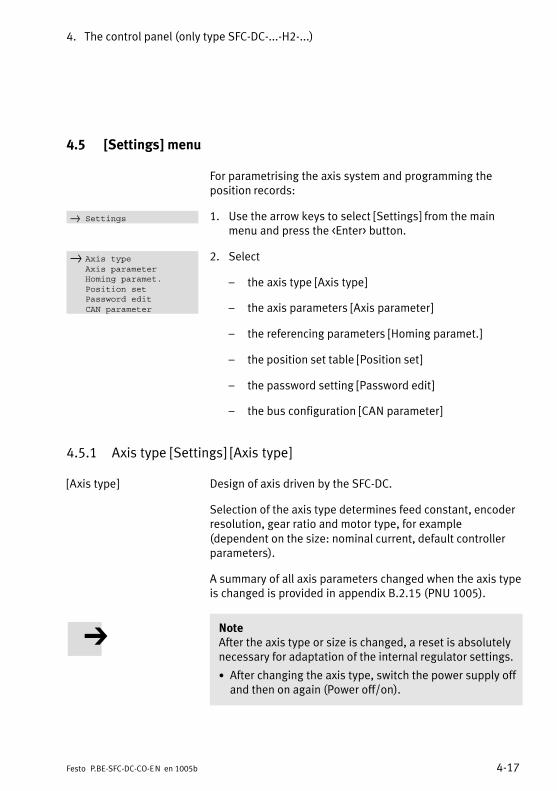
4. The control panel (only type SFC−DC−...−H2−...)
4−17Festo P.BE−SFC−DC−CO−EN en 1005b
4.5 [Settings] menu
For parametrising the axis system and programming theposition records:
1. Use the arrow keys to select [Settings] from the mainmenu and press the <Enter> button.
2. Select
� the axis type [Axis type]
� the axis parameters [Axis parameter]
� the referencing parameters [Homing paramet.]
� the position set table [Position set]
� the password setting [Password edit]
� the bus configuration [CAN parameter]
4.5.1 Axis type [Settings] [Axis type]
[Axis type] Design of axis driven by the SFC−DC.
Selection of the axis type determines feed constant, encoderresolution, gear ratio and motor type, for example(dependent on the size: nominal current, default controllerparameters).
A summary of all axis parameters changed when the axis typeis changed is provided in appendix B.2.15 (PNU 1005).
NoteAfter the axis type or size is changed, a reset is absolutelynecessary for adaptation of the internal regulator settings.
· After changing the axis type, switch the power supply offand then on again (Power off/on).
} Settings
} Axis typeAxis parameterHoming paramet.Position setPassword editCAN parameter

4. The control panel (only type SFC−DC−...−H2−...)
4−18 Festo P.BE−SFC−DC−CO−EN en 1005b
1. First select the manufacturer of the drive.
[Axis type] Parameter
[Festo] Drives from Festo. Select the type used corresponding to Tab.�4/15:
[Sommer] Drives from Sommer Co. Select the type used corresponding to Tab.�4/16:
Tab.�4/14: Elements [Axis type] � manufacturer selection
2. Subsequently select the product family and then the typeof drive.
[Festo] Parameter
[SLTE] Electric mini−slide from Festo. Select the type used:� SLTE10−50−G04: Type SLTE−10−50−LS5,0−DC−VCSC−G04� SLTE10−80−G04: Type SLTE−10−80−LS5,0−DC−VCSC−G04� SLTE10−xx Mini slide SLTE size 10, stroke and gear ratio
user−defined, see Tab.�4/17.� SLTE16−50−G04: Type SLTE−16−50−LS7,5−DC−VCSC−G04� SLTE16−80−G04: Type SLTE−16−80−LS7,5−DC−VCSC−G04� SLTE16−100−G04: Type SLTE−16−100−LS7,5−DC−VCSC−G04� SLTE16−150−G04: Type SLTE−16−150−LS7,5−DC−VCSC−G04� SLTE16−xx Mini slide SLTE size 16, stroke and gear ratio
user−defined, see Tab.�4/17.
[HGP] Electric gripper from Festo. Select the type used:� HGPLE−14−30: Type HGPLE−14−30, in preparation� HGPLE−14−60: Type HGPLE−14−60, in preparation� HGPLE−14−xx: Gripper HGPLE size 14, stroke and gear ratio
user−defined, see Tab.�4/17.� HGPLE−25−40: Type HGPLE−25−40−2,8−DC−VCSC−G85,
Stroke per gripper jaw 40 mm, total 80 mm.� HGPLE−25−80: Type HGPLE−25−80, in preparation� HGPLE−25−xx: Gripper HGPLE size 25, stroke and gear ratio
user−defined, see Tab.�4/17.
Support for further drives is in preparation.
Tab.�4/15: Selection of axis type � Manufacturer Festo
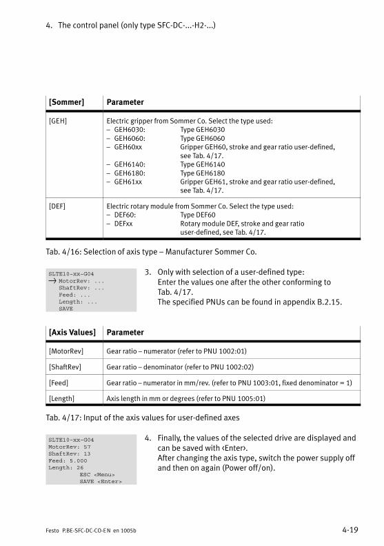
4. The control panel (only type SFC−DC−...−H2−...)
4−19Festo P.BE−SFC−DC−CO−EN en 1005b
[Sommer] Parameter
[GEH] Electric gripper from Sommer Co. Select the type used:� GEH6030: Type GEH6030� GEH6060: Type GEH6060� GEH60xx Gripper GEH60, stroke and gear ratio user−defined,
see Tab.�4/17.� GEH6140: Type GEH6140� GEH6180: Type GEH6180� GEH61xx Gripper GEH61, stroke and gear ratio user−defined,
see Tab.�4/17.
[DEF] Electric rotary module from Sommer Co. Select the type used:� DEF60: Type DEF60� DEFxx Rotary module DEF, stroke and gear ratio
user−defined, see Tab.�4/17.
Tab.�4/16: Selection of axis type � Manufacturer Sommer Co.
3. Only with selection of a user−defined type: Enter the values one after the other conforming toTab.�4/17. The specified PNUs can be found in appendix B.2.15.
[Axis Values] Parameter
[MotorRev] Gear ratio � numerator (refer to PNU 1002:01)
[ShaftRev] Gear ratio � denominator (refer to PNU 1002:02)
[Feed] Gear ratio � numerator in mm/rev. (refer to PNU 1003:01, fixed denominator = 1)
[Length] Axis length in mm or degrees (refer to PNU 1005:01)
Tab.�4/17: Input of the axis values for user−defined axes
4. Finally, the values of the selected drive are displayed andcan be saved with <Enter>.After changing the axis type, switch the power supply offand then on again (Power off/on).
SLTE10−xx−G04} MotorRev: ...
ShaftRev: ...Feed: ...Length: ...SAVE
SLTE10−xx−G04MotorRev: 57ShaftRev: 13Feed: 5.000Length: 26
ESC <Menu>SAVE <Enter>

4. The control panel (only type SFC−DC−...−H2−...)
4−20 Festo P.BE−SFC−DC−CO−EN en 1005b
4.5.2 Axis parameter [Settings] [Axis parameter]
[Axis parameter] Teach mode for setting the axis parameters
WarningDuring the teach procedure for specifying the axis zeropoint and the stroke limitation, the motor turns or theconnected drive starts to move.
· Make sure that nobody can reach into the positioningrange of the moveable load and that there are no objectsin its path.
[Axis parameter] Description
[Zero point] Offset axis zero point
[SW−limit−neg] Stroke limitation: software end position,negative
[SW−limit−pos] Stroke limitation: Software end position,positive
[SAVE...] Save parameters in EEPROM
Tab.�4/18: Elements [Axis parameter]
NoteThe set parameters take effect immediately afterconfirmation with OK <ENTER>. The settings are savedpermanently in EEPROM with the [SAVE...] menucommand:
· Choose [SAVE...] to save the parameter settings.Only�then will the settings be retained even afterswitching off the power supply or in the event of a powerfailure.

4. The control panel (only type SFC−DC−...−H2−...)
4−21Festo P.BE−SFC−DC−CO−EN en 1005b
4.5.3 Reference travel parameter [Settings] [Homing paramet.]
[Homing paramet.] Sets the referencing method and the speeds during thereference run.
The maximum speed during the reference run is limited to10�mm/s.
[Hom. paramet.] Param. Description
[Homing method] block negative Homing to fixed stop,negative = factory setting
block positive Homing tofixed stop, positive
switch negative Homing to referenceswitch, negative withindex search
switch positive Homing to referenceswitch, positive withindex search
[Velocity v_rp] v_rp Speed for searching forthe reference point
[Velocity v_zp] v_zp Speed for moving to theaxis zero point
[SAVE...] Save parameters in EEPROM
Tab.�4/19: Elements [Homing paramet.]
NoteThe set parameters take effect immediately afterconfirmation with OK <ENTER>. The settings are savedpermanently in EEPROM with the [SAVE...] menucommand:
· Choose [SAVE...] to save the parameter settings.Only�then will the settings be retained even afterswitching off the power supply or in the event of a powerfailure.
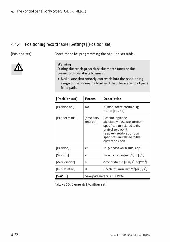
4. The control panel (only type SFC−DC−...−H2−...)
4−22 Festo P.BE−SFC−DC−CO−EN en 1005b
4.5.4 Positioning record table [Settings] [Position set]
[Position set] Teach mode for programming the position set table.
WarningDuring the teach procedure the motor turns or theconnected axis starts to move.
· Make sure that nobody can reach into the positioningrange of the moveable load and that there are no objectsin its path.
[Position set] Param. Description
[Position no.] No. Number of the positioningrecord�[1 ... 31]
[Pos set mode] [absolute/relative]
Positioning modeabsolute = absolute positionspecification, related to theproject zero pointrelative = relative positionspecification, related to thecurrent position
[Position] xt Target position in [mm] or [°]
[Velocity] v Travel speed in [mm/s] or [°/s]
[Acceleration] a Acceleration in [mm/s2] or [°/s2]
[Deceleration] d Deceleration in [mm/s2] or [°/s2]
[SAVE...] Save parameters in EEPROM
Tab.�4/20: Elements [Position set.]
4. The control panel (only type SFC−DC−...−H2−...)
4−23Festo P.BE−SFC−DC−CO−EN en 1005b
NoteThe set parameters take effect immediately afterconfirmation with OK <ENTER>. The settings are savedpermanently in EEPROM with the [SAVE...] menucommand:
· Choose [SAVE...] to save the parameter settings.Only�then will the settings be retained even afterswitching off the power supply or in the event of a powerfailure.
4.5.5 Password [Settings] [Password edit]
Access via the control panel can be protected by a (local)password in order to prevent unauthorized or unintentionaloverwriting or modification of parameters in the device.No�password has been preset at the factory(presetting�=�000).
· Keep the password for the SFC−DC in a safe place,e.�g.�in�the internal documentation for your system.
If the active password in the SFC−DC should be lost in spite ofcare being taken:The password can be deleted by entering a master passwordif necessary. In this case please contact your Festo servicepartner.

4. The control panel (only type SFC−DC−...−H2−...)
4−24 Festo P.BE−SFC−DC−CO−EN en 1005b
Activating a password
[Password edit] Select [Password edit] from the [Settings] menu:
Enter a password with 3 digits. The current input position ismarked with a question mark.
1. Use the arrow buttons to select a digit 0 ... 9.
2. Confirm your input with <Enter>. The next entry positionwill be displayed.
3. Set a digit for the next input position.
4. Save your setting after entering the third digit by pressing[SAVE...] <Enter>.
After saving, access to all parameter and control functions ofthe control panel is blocked through password query.
Enter password
As soon as a password is active, it will be scannedautomatically when the menu commands [Positioning],[Settings] or [HMI control] are accessed. When the correctpassword is entered, all parametrisation and controlfunctions of the control panel are enabled until the powersupply is switched off.
The current input position is marked with a question mark.
1. Use the arrow buttons to select a digit 0 ... 9.
2. Confirm your input with <Enter>. The next entry positionwill be displayed.
3. Repeat the entry for the remaining entry positions.
When the correct password is entered, all parametrisationand control functions of the control panel are enabled untilthe power supply is switched off.
New Password:[ ? x x ] = 0
ESC <Menu>EDIT <−−> OK <Enter>
Enter Password:[ ? x x ] = 0
ESC <Menu>EDIT <−−> OK <Enter>

4. The control panel (only type SFC−DC−...−H2−...)
4−25Festo P.BE−SFC−DC−CO−EN en 1005b
Changing/deactivating the password
[Password edit] Select [Password edit] in the [Settings] menu:
Enter the existing password with 3 digits. The current inputposition is marked with a question mark.
1. Use the arrow keys to select a digit 0 ... 9.
2. Confirm your entry with OK <Enter>. The next entryposition will be displayed.
3. Repeat the entry for the remaining entry positions.
4. Enter the new password with 3 digits. If you wish todeactivate the password, enter �000".
5. Save your setting after entering the last digit by pressing[SAVE...] <Enter>.
Enter Password:[ ? x x ] = 0
ESC <Menu>EDIT <−−> OK <Enter>
New Password:[ ? x x ] = 0
ESC <Menu>EDIT <−−> OK <Enter>

4. The control panel (only type SFC−DC−...−H2−...)
4−26 Festo P.BE−SFC−DC−CO−EN en 1005b
4.5.6 Bus parameter [Settings] [CAN parameter]
[CAN parameter] Set the fieldbus parameters.
[CANparameters]
Param. Description
[CAN node ID] 1 ... 127(1 ... 7Fh)
Field bus address of the SFC−DC.Representation:�1 dec, 1 hex" ... �127 dec, 7f hex"
[CAN baud rate] 1000 kBd,800 kBd,500 kBd,250 kBd,125 kBd,100 kBd,50 kBd,20 kBd
Fieldbus baud rate as per settingson master.
[CAN profiles] DS 402,FHPP
Pre−set data profile.Controller/device profile with whichcommunication between the CANmaster and the SFC−DC is handled.� DS 402:
The SFC−DC is controlled inaccordance with DS 402.
� FHPP: The SFC−DC is controlled as perthe Festo Handling andPositioning Profile.
[CANVolt.Supply]
internal,external
Supply to CAN interface;see�chapter 3.7.
Tab.�4/21: [CAN Parameter] items
The settings in the menu [CAN parameter] are saved directlyand permanently (including in the event of a power failure) inthe EEPROM after confirmation with OK<Enter>.

Commissioning
5−1Festo P.BE−SFC−DC−CO−EN en 1005b
Chapter 5

5. Commissioning
5−2 Festo P.BE−SFC−DC−CO−EN en 1005b
Contents
5.1 Preparations for commissioning 5−4 . . . . . . . . . . . . . . . . . . . . . . . . . . . . . . . . . . .
5.1.1 Check the connection to the mains power supply 5−4 . . . . . . . . . . . . . .
5.1.2 Checking the drive 5−4 . . . . . . . . . . . . . . . . . . . . . . . . . . . . . . . . . . . . . . .
5.1.3 General instructions on commissioning 5−5 . . . . . . . . . . . . . . . . . . . . . .
5.2 Commissioning with the control panel (only type SFC−DC−...−H2−...) 5−8 . . . . . . .
5.2.1 Setting the axis type 5−10 . . . . . . . . . . . . . . . . . . . . . . . . . . . . . . . . . . . . .
5.2.2 Setting the reference run parameters 5−10 . . . . . . . . . . . . . . . . . . . . . . .
5.2.3 Starting a homing run 5−15 . . . . . . . . . . . . . . . . . . . . . . . . . . . . . . . . . . . .
5.2.4 Teach the axis zero point and the software end positions 5−16 . . . . . . .
5.2.5 Positioning with position sets 5−18 . . . . . . . . . . . . . . . . . . . . . . . . . . . . . .
5.2.6 Teach position records 5−19 . . . . . . . . . . . . . . . . . . . . . . . . . . . . . . . . . . .
5.2.7 Test run 5−21 . . . . . . . . . . . . . . . . . . . . . . . . . . . . . . . . . . . . . . . . . . . . . . .
5.2.8 Setting CAN parameters 5−22 . . . . . . . . . . . . . . . . . . . . . . . . . . . . . . . . . .
5.3 Commissioning with the Festo Configuration Tool 5−26 . . . . . . . . . . . . . . . . . . . . .
5.3.1 Installing and starting the Festo Configuration Tool 5−26 . . . . . . . . . . . .
5.3.2 Procedure for commissioning with the Festo Configuration Tool 5−27 . .
5.4 Commissioning on a CANopen master 5−29 . . . . . . . . . . . . . . . . . . . . . . . . . . . . . .
5.4.1 General information on CANopen 5−30 . . . . . . . . . . . . . . . . . . . . . . . . . . .
5.4.2 Overview of commissioning on the field bus 5−31 . . . . . . . . . . . . . . . . . .
5.4.3 Configuration of the CANopen master 5−32 . . . . . . . . . . . . . . . . . . . . . . .
5.4.4 Communication 5−33 . . . . . . . . . . . . . . . . . . . . . . . . . . . . . . . . . . . . . . . . .
5.4.5 PDO mapping 5−34 . . . . . . . . . . . . . . . . . . . . . . . . . . . . . . . . . . . . . . . . . . .
5.5 Festo handling and positioning profile (FHPP) 5−37 . . . . . . . . . . . . . . . . . . . . . . . .
5.5.1 Supported operation modes 5−37 . . . . . . . . . . . . . . . . . . . . . . . . . . . . . . .
5.5.2 Composition of the cyclic I/O data (FHPP standard) 5−39 . . . . . . . . . . . .
5.5.3 Description of the I/O data (Record select) 5−41 . . . . . . . . . . . . . . . . . . .
5.5.4 Description of the I/O data (Direct mode) 5−42 . . . . . . . . . . . . . . . . . . . .
5.5.5 Description of the control bytes CCON, CPOS, CDIR 5−43 . . . . . . . . . . . .
5.5.6 Description of the status bytes SCON, SPOS, SDIR (RSB) 5−46 . . . . . . .
5.5.7 Examples of the I/O data 5−49 . . . . . . . . . . . . . . . . . . . . . . . . . . . . . . . . .

5. Commissioning
5−3Festo P.BE−SFC−DC−CO−EN en 1005b
5.6 Sequence control as per FHPP standard 5−62 . . . . . . . . . . . . . . . . . . . . . . . . . . . .
5.6.1 Homing 5−62 . . . . . . . . . . . . . . . . . . . . . . . . . . . . . . . . . . . . . . . . . . . . . . . .
5.6.2 Jog mode 5−64 . . . . . . . . . . . . . . . . . . . . . . . . . . . . . . . . . . . . . . . . . . . . . .
5.6.3 Teaching via field bus 5−66 . . . . . . . . . . . . . . . . . . . . . . . . . . . . . . . . . . . .
5.6.4 Record selection (positioning mode) 5−68 . . . . . . . . . . . . . . . . . . . . . . . .
5.6.5 Direct mode (positioning mode, power operation) 5−73 . . . . . . . . . . . . .
5.6.6 Standstill monitoring 5−80 . . . . . . . . . . . . . . . . . . . . . . . . . . . . . . . . . . . . .
5.7 FHPP finite state machine 5−82 . . . . . . . . . . . . . . . . . . . . . . . . . . . . . . . . . . . . . . . .
5.7.1 Create ready status 5−84 . . . . . . . . . . . . . . . . . . . . . . . . . . . . . . . . . . . . . .
5.7.2 Positioning 5−85 . . . . . . . . . . . . . . . . . . . . . . . . . . . . . . . . . . . . . . . . . . . . .
5.8 Instructions on operation 5−87 . . . . . . . . . . . . . . . . . . . . . . . . . . . . . . . . . . . . . . . . .
5. Commissioning
5−4 Festo P.BE−SFC−DC−CO−EN en 1005b
5.1 Preparations for commissioning
5.1.1 Check the connection to the mains power supply
NoteMake sure that the tolerances for the supply voltage areobserved. The tolerances must also be observed directlyat the logic and operating voltage connection of theSFC−DC.
The correct values can be found in chapter 3.2 and in thetechnical specifications in the appendix.
5.1.2 Checking the drive
WarningDanger of injury.
Electric axes can move suddenly with high force and athigh speed. Collisions can lead to serious injury to peopleand damage to components.
· Make sure that nobody can gain access to the operatingrange of the axis or of other connected actuators andthat no objects lie in the path of the axes while thesystem is still connected to a power supply (voltage).
NoteDuring operation, the drive must not strike a stop withoutshock absorption (exceptions: homing, force mode).
Recommendation: Use shock absorbers or other suitablebuffer elements on all stops where no reference run isbeing carried out.

5. Commissioning
5−5Festo P.BE−SFC−DC−CO−EN en 1005b
· Before commissioning the positioning drive,make�sure�that:
� the work space is of sufficient size for operation with awork load,
� the work load does not collide with the motor or thegear of the axis when the axis moves into the endposition,
� the positioning drive is within the permittedpositioning range when it is switched on.
· Observe the notes in the operating instructions for yourpositioning drive.
5.1.3 General instructions on commissioning
WarningDanger of injury.
Errors in parametrisation can cause injury to people anddamage to property. In the following cases reference travelis absolutely essential in order that the referencecoordinates and the working range can be set correctly:
� during initial commissioning,
� when the referencing method is changed,
� each time the logic voltage supply is switched on.
CautionFaults may occur if you attempt to access control andoperating functions with the Festo Configuration Tool andthe control panel at the same time.
· Make sure that the Festo Configuration Tool, the controlpanel and the control interface of the SFC−DC are notused at the same time.
5. Commissioning
5−6 Festo P.BE−SFC−DC−CO−EN en 1005b
NoteIn the following cases it is not permitted to write−accessthe SFC−DC with the Festo Configuration Tool(e.g.�downloading parameters) or controlling(e.g.�with��Move manually" or when starting homing):
� When the SFC−DC is currently performing a positioningmovement or when a movement is started during access(e.g. via the control interface or via the control panel).
� When parametrisation or operation with the controlpanel takes place on the SFC−DC.
Observe the following:
· The device connection in the Festo Configuration Toolmust not be activated when the control panel is beingused for control (�HMI control = on").
· Control with the control panel (�HMI control = on") mustnot be activated when the device connection in theFesto�Configuration Tool is activated.
· Control by the Festo Configuration Tool must not beactivated while the drive is in motion or when control isbeing carried out via the controller interface.

5. Commissioning
5−7Festo P.BE−SFC−DC−CO−EN en 1005b
First steps in commissioning
1. Switch on the power supply for the SFC−DC.
2. Check (if your drive has been configured at the factory)the settings in the menu [Diagnostic].
3. Carry out parametrisation and commissioning with thecontrol panel or the Festo Configuration Tool,as�described in the following sections and in theFesto�Configuration Tool/PlugIn help.For commissioning, the mechanical structure must beconfigured and a measuring system must be defined forreferencing the reference coordinates. By means of themeasuring system all positions are defined andmovement can be made to them. Explanations ofreference coordinates and the working area can be foundin chapter 1.6.
4. In order to complete commissioning note the instructionsfor operation in the Festo Configuration Tool/PlugIn helpand in chapter 5.8.
NoteTo restore the default settings, the EEPROM can be deletedif necessary with CI object 20F1 (Data memory control)directly via the serial interface (see appendix B.2.5and�C.4). User−specific settings will then be lost.
· Use CI commands only if you already have experience ofService Data Objects
· If necessary, consult Festo.

5. Commissioning
5−8 Festo P.BE−SFC−DC−CO−EN en 1005b
5.2 Commissioning with the control panel (only type SFC−DC−...−H2−...)
Working with the control panel
Information on the button functions and on the menucomposition of the control panel can be found in chapter 4.
Device control
In order for the control panel to control the connectedSFC−DC, the control interface of the SFC−DC must bedeactivated and the controller enable must be set.[HMI�=�on]. The actual status of the FHPP control bytes or thetransmitted DS402 control word is then without effect.
Instructions on control enable can be found in chapter 4.2.3.
DiagnosticPositioningSettings
} HMI controlLCD adjustment
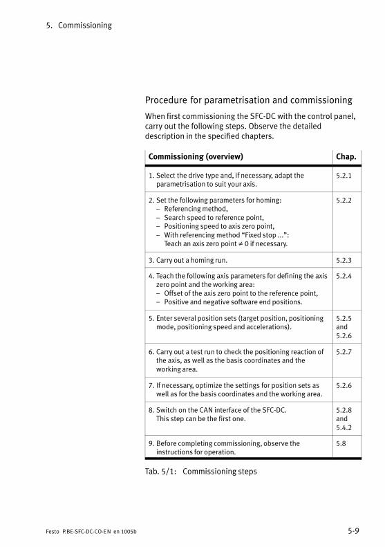
5. Commissioning
5−9Festo P.BE−SFC−DC−CO−EN en 1005b
Procedure for parametrisation and commissioning
When first commissioning the SFC−DC with the control panel,carry out the following steps. Observe the detaileddescription in the specified chapters.
Commissioning (overview) Chap.
1. Select the drive type and, if necessary, adapt theparametrisation to suit your axis.
5.2.1
2. Set the following parameters for homing:� Referencing method,� Search speed to reference point,� Positioning speed to axis zero point,� With referencing method �Fixed stop ...":
Teach an axis zero point � 0 if necessary.
5.2.2
3. Carry out a homing run. 5.2.3
4. Teach the following axis parameters for defining the axiszero point and the working area:� Offset of the axis zero point to the reference point,� Positive and negative software end positions.
5.2.4
5. Enter several position sets (target position, positioningmode, positioning speed and accelerations).
5.2.5and5.2.6
6. Carry out a test run to check the positioning reaction ofthe axis, as well as the basis coordinates and theworking area.
5.2.7
7. If necessary, optimize the settings for position sets aswell as for the basis coordinates and the working area.
5.2.6
8. Switch on the CAN interface of the SFC−DC.This step can be the first one.
5.2.8and5.4.2
9. Before completing commissioning, observe theinstructions for operation.
5.8
Tab.�5/1: Commissioning steps

5. Commissioning
5−10 Festo P.BE−SFC−DC−CO−EN en 1005b
5.2.1 Setting the axis type
1. Select the axis used in the menu [Settings] [Axis type],as�described in chapter 4.5.1.
2. Check the displayed values of the drive and save thesetting with SAVE <Enter>.
NoteAfter the axis type or size is changed, a reset is absolutelynecessary for adaptation of the internal regulator settings.
· After changing the size, switch the power supply off andthen on again (Power off/on).
5.2.2 Setting the reference run parameters
In order to search for the reference point and for positioningthe drive in the axis zero point, you can set two differentspeeds. The maximum possible speed is limited at thefactory.
Depending on the referencing method, the reference point isdefined by means of a reference switch or fixed stop.
SLTE10−xx−G04MotorRev: 57ShaftRev: 13Feed: 5.000Length: 26
ESC <Menu>SAVE <Enter>

5. Commissioning
5−11Festo P.BE−SFC−DC−CO−EN en 1005b
Notes on referencing to the fixed stop
NoteReference travel may only be carried out directly againstthe fixed stop if the permitted impact pulse is notexceeded.
· Operate the positioning drive only with the permittedmass.
CautionDamage to components
The drive with positioning controller SFC−DC moves duringhoming to a mechanical stop with adjustable nominalmotor torque (default: 100 % of nominal current).
· Limit the maximum current during the reference run bymeans of
� the Festo Configuration Tool(see�help�for�plug−in�SFC−DC)
� the PNU 1034 or object 6073h (see appendix B.2.18).
CautionDamage to components
During operation it is not permitted to move to themechanical end positions (stops). If movement is made tothe end positions with a heavy load, jamming may occur inthe end positions.
· Set the offset of the axis zero point � 0, e.g.�+1.00 mmwhen referencing to a negative mechanical stop or−1.00�mm when referencing to a positive mechanicalstop, for grippers set to +0.50 mm or −0.50 mmcorrespondingly.
· Limit the positioning range by defining valid softwareend positions during commissioning (see chapter 1.6).
· Specify target positions only within the permittedpositioning range.

5. Commissioning
5−12 Festo P.BE−SFC−DC−CO−EN en 1005b
Notes on referencing to the reference switch
If homing to a mechanical end position in the application orwith rotary drives is not possible, an external sensor(reference switch) can be used as reference signal(see�also�chapter 1.6).
Special case 1: At the start of homing, the axis stands onthe reference switch
If the axis stands on the reference switch at the start ofhoming it will move in the opposite direction to the referenceswitch (see 2 in Tab.�1/6).
The axis then moves as usual to the axis zero point(compare�2 in Tab.�1/6).
Special case 2: The axis cannot find a reference switchduring homing
If the axis cannot find a reference switch during homing, it willmove until it strikes a stop. It will then remain at the stop untilthe fault HOMING ERROR is displayed (see chapter 6.3).
The reasons for this can be:
� at the start of homing, the axis already stands behind thereference switch,
� the reference switch is defective,
� the axis is defective or fitted incorrectly, e.g. the coupling�does not grip".
5. Commissioning
5−13Festo P.BE−SFC−DC−CO−EN en 1005b
Homing must be repeated after the error message has beenacknowledged:
· Acknowledge the error message with <Enter>.
· If necessary, check the function of the reference switch.
· Check the settings of the parameters.
· If necessary, position the drive in Teach mode so that atthe start it stands in the search direction in front of thestop or reference switch.
· Repeat the homing run.

5. Commissioning
5−14 Festo P.BE−SFC−DC−CO−EN en 1005b
Setting parameters
1. Set the following homing parameters one after the other:
� The referencing method [Homing method]
� The search speed for ascertaining the reference point[Velocity v_rp]
� The positioning speed to the axis zero point.[Velocity�v_zp].
2. With referencing method �Fixed stop": Make sure that the axis zero point is � 0.If necessary, teach the axis zero point (see chapter 5.2.4).
CautionIf the referencing method is changed, the offset of the axiszero point will be reset to zero. Existing settings of thesoftware end positions and of the target positions of theposition set table will be retained. Note that these valuesrefer to the previous axis zero point.
· Always carry out a reference run after changing thereferencing method.
· Then teach the offset of the axis zero point.
If the axis zero point is modified:
· Teach the software end positions and the targetpositions again.
3. Accept each setting with OK <Enter>. The setting will thentake effect in the drive.
4. Save the parameter settings with SAVE <Enter>.Only�then�will the settings be retained even afterswitching off the power supply or in the event of a powerfailure.
5. Finally, carry out homing, otherwise the previousreference system of the SFC−DC will remain unmodified.
} SettingsHoming paramet.
Homing methodVelocity v_rpVelocity v_zpSAVE...
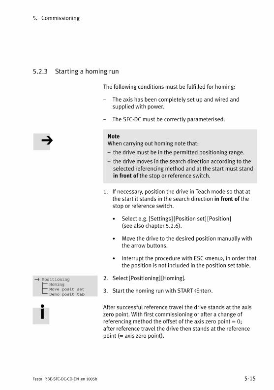
5. Commissioning
5−15Festo P.BE−SFC−DC−CO−EN en 1005b
5.2.3 Starting a homing run
The following conditions must be fulfilled for homing:
� The axis has been completely set up and wired andsupplied with power.
� The SFC−DC must be correctly parameterised.
NoteWhen carrying out homing note that:
� the drive must be in the permitted positioning range.
� the drive moves in the search direction according to theselected referencing method and at the start must standin front of the stop or reference switch.
1. If necessary, position the drive in Teach mode so that atthe start it stands in the search direction in front of thestop or reference switch.
· Select e.g. [Settings] [Position set] [Position](see�also�chapter 5.2.6).
· Move the drive to the desired position manually withthe arrow buttons.
· Interrupt the procedure with ESC <menu>, in order thatthe position is not included in the position set table.
2. Select [Positioning] [Homing].
3. Start the homing run with START <Enter>.
After successful reference travel the drive stands at the axiszero point. With first commissioning or after a change ofreferencing method the offset of the axis zero point = 0;after�reference travel the drive then stands at the referencepoint (= axis zero point).
} PositioningHomingMove posit setDemo posit tab
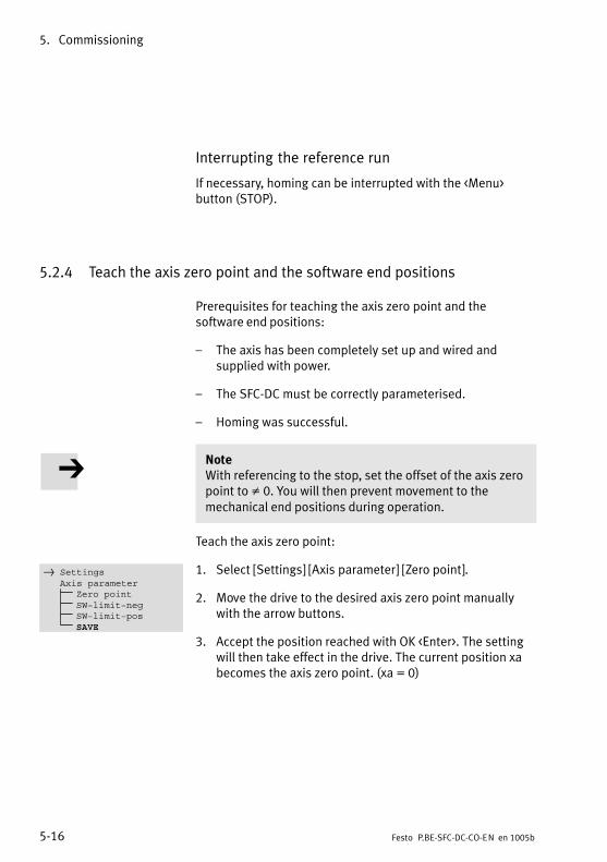
5. Commissioning
5−16 Festo P.BE−SFC−DC−CO−EN en 1005b
Interrupting the reference run
If necessary, homing can be interrupted with the <Menu>button (STOP).
5.2.4 Teach the axis zero point and the software end positions
Prerequisites for teaching the axis zero point and thesoftware end positions:
� The axis has been completely set up and wired andsupplied with power.
� The SFC−DC must be correctly parameterised.
� Homing was successful.
NoteWith referencing to the stop, set the offset of the axis zeropoint to � 0. You will then prevent movement to themechanical end positions during operation.
Teach the axis zero point:
1. Select [Settings] [Axis parameter] [Zero point].
2. Move the drive to the desired axis zero point manuallywith the arrow buttons.
3. Accept the position reached with OK <Enter>. The settingwill then take effect in the drive. The current position xabecomes the axis zero point. (xa = 0)
} SettingsAxis parameter
Zero pointSW−limit−negSW−limit−posSAVE

5. Commissioning
5−17Festo P.BE−SFC−DC−CO−EN en 1005b
NoteIf the axis zero point is modified:
Check existing settings of the software end positions andof target positions in the position table. Note that thesevalues refer to the previous axis zero point.
· Teach the software end positions and the targetpositions again.
Teach the negative and the positive software end positions:
1. Select [Settings] [Axis parameter] [SW−limit−neg] or[SW−limit−pos].
2. Move the drive manually with the arrow buttons.
3. Accept the position reached with OK <Enter>. The settingwill then take effect in the drive.
4. Save the parameter settings with [SAVE]. Only then willthe settings be retained even after switching off thepower supply or in the event of a power failure.

5. Commissioning
5−18 Festo P.BE−SFC−DC−CO−EN en 1005b
5.2.5 Positioning with position sets
The following conditions must be fulfilled:
� The axis has been completely set up and wired andsupplied with power.
� The SFC−DC must be correctly parameterised.
� Homing has been carried out successfully.
� The axis zero point and the software end positions havebeen set correctly.
NoteNote that positioning sets with speed v=0 or an invalidtarget position (−> error: TARGET POSITION OUT OF LIMIT)will not be executed.
· After successful homing carry out a test run, if necessary,without a work load (see chapter 5.2.7).
· If necessary, optimize the settings for position sets as wellas for the reference coordinates and the working area(see chapter 1.6).
· After a successful test run you can teach the positions inthe position set table to which movement must be made(see chapter 5.2.6).
WarningDuring the teach procedure the motor turns or theconnected axis starts to move.
· Make sure that nobody can place his/her hand in thepositioning range of the moveable mass and that noobjects lie in its path.

5. Commissioning
5−19Festo P.BE−SFC−DC−CO−EN en 1005b
5.2.6 Teach position records
Enter the positioning records as follows:
1. Activate the desired position set (1 ... 31) with [Settings][Position set] [Position nr].
2. Complete or correct the positioning mode of the positionset:
· Select [Pos set mode].
· Set the positioning mode with the arrow keys:absolute= absolute position specification,
related to the project zero pointrelative = relative position specification,
related to the current position
· Accept the value with OK <Enter>.
NoteIf you modify the positioning mode, you must then teachagain the target position of the position set, otherwise themodification of the positioning mode will not be accepted.
3. Teach the target position of the position record:
· Select [Position]
· Move the drive manually to the desired target positionwith the arrow keys.
· Accept the position reached with OK <Enter>.The�setting of the target position and the positioningmode will then take effect in the drive.
Only positioning jobs can be executed with positioningrecords. Force mode is not possible.
} SettingsPosition set
Position nrPos set modePositionVelocityAccelerationDecelerationSAVE

5. Commissioning
5−20 Festo P.BE−SFC−DC−CO−EN en 1005b
4. Complete or correct the speed.
· Select [Velocity].
· Set the nominal speed with the arrow keys.
· Accept the setting with OK <Enter>. The setting willthen take effect in the drive.
5. Complete or correct the acceleration value of theacceleration ramp of the position set.
· Select [Acceleration].
· Set the nominal acceleration with the arrow keys.
· Accept the setting with OK <Enter>. The setting willthen take effect in the drive.
6. Complete or correct the deceleration value of the brakingramp of the position set.
· Select [Deceleration].
· Set the nominal acceleration with the arrow keys.
· Accept the setting with OK <Enter>. The setting willthen take effect in the drive.
7. Save the position set table with [SAVE]. Only then will thesettings be retained even after switching off the powersupply or in the event of a power failure.
8. Enter the next positioning record.
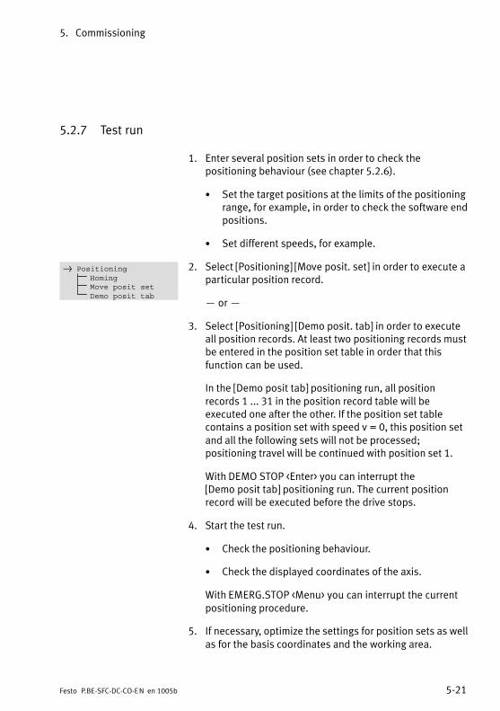
5. Commissioning
5−21Festo P.BE−SFC−DC−CO−EN en 1005b
5.2.7 Test run
1. Enter several position sets in order to check thepositioning behaviour (see chapter 5.2.6).
· Set the target positions at the limits of the positioningrange, for example, in order to check the software endpositions.
· Set different speeds, for example.
2. Select [Positioning] [Move posit. set] in order to execute aparticular position record.
� or �
3. Select [Positioning] [Demo posit. tab] in order to executeall position records. At least two positioning records mustbe entered in the position set table in order that thisfunction can be used.
In the [Demo posit tab] positioning run, all positionrecords 1 ... 31 in the position record table will beexecuted one after the other. If the position set tablecontains a position set with speed v = 0, this position setand all the following sets will not be processed;positioning travel will be continued with position set 1.
With DEMO STOP <Enter> you can interrupt the[Demo�posit tab] positioning run. The current positionrecord will be executed before the drive stops.
4. Start the test run.
· Check the positioning behaviour.
· Check the displayed coordinates of the axis.
With EMERG.STOP <Menu> you can interrupt the currentpositioning procedure.
5. If necessary, optimize the settings for position sets as wellas for the basis coordinates and the working area.
} PositioningHomingMove posit setDemo posit tab

5. Commissioning
5−22 Festo P.BE−SFC−DC−CO−EN en 1005b
5.2.8 Setting CAN parameters
Before commissioning on CANopen, valid CAN parametersmust be set.
Station number (CAN Node ID)
� Permitted station numbers: 1 ... 127.
� The default setting is the invalid station number 0(displayed on the control panel as �???")This is to make sure that a correct address is set duringcommissioning or exchange.
Recommendation:Assign the station numbers in ascending order. Assign thestation numbers in accordance with the machine structure ofyour system.
NoteStation numbers may be assigned only once per fieldbusline.
Set the station number as follows:
1. Select [Settings] [CAN parameter] [CAN Node ID](see�also�chapter 4.5).
2. The current address is displayed with <Enter>.
3. Set the desired address with the arrow buttons.
4. Accept the address with OK <Enter>. The pre−set address is permanently saved, though it willnot take effect until after a Power off/on!
} SettingsCAN parameter
CAN node ID
CAN node ID
110 dec, 6e hex
ESC <Menu>EDIT <−−> OK <Enter>

5. Commissioning
5−23Festo P.BE−SFC−DC−CO−EN en 1005b
Baud rate (CAN Baud rate)
� Possible baud rates: 1000 kBd (1 MBaud), 800 kBd, 500 kBd, 250 kBd,125�kBd, 100 kBd, 50 kBd, 20 kBd.
� The default setting is an invalid baud rate (displayed on the control panel as �???")This is to make sure that a correct baud rate is set duringcommissioning or exchange.
NoteAll the stations on a field bus line must use the same baudrate. Otherwise no communication will be possible.
Set the baud rate as follows:
1. Select [Settings] [CAN parameter] [CAN Baud rate](see�also chapter 4.5).
2. Press <Enter> to display the current baud rate.
3. Use the arrow keys to set the desired baud rate.
4. Accept the baud rate with OK <Enter>. The pre−set baud rate is permanently saved, though it willnot take effect until after a Power off/on!
} SettingsCAN parameter
CAN baud rate
CAN baud rate
1000 kBd
ESC <Menu>EDIT <−−> OK <Enter>

5. Commissioning
5−24 Festo P.BE−SFC−DC−CO−EN en 1005b
Data profile (CAN profile)
� Possible data profiles:
� FHPP:The SFC−DC is activated and parameterised as per theFesto Handling and Positioning Profile.
� DS 402:The SFC−DC is activated and parameterised inaccordance with DS 402.
� The default setting is an invalid data profile(displayed�on the control panel as �???")This is to make sure that the correct data profile is setduring commissioning or exchange.
For information on the data profile see chapter 1.7.2.
Set the data profile as follows:
1. Select [Settings] [CAN parameter] [CAN profile](see�also�chapter 4.5).
2. Press <Enter> to display the current data profile.
3. Use the arrow keys to set the desired data profile.
4. Accept the data profile with OK <Enter>. The pre−set profile takes effect immediately, and is savedagainst network failure.
} SettingsCAN parameter
CAN profile
CAN profile
FHPP
ESC <Menu>EDIT <−−> OK <Enter>

5. Commissioning
5−25Festo P.BE−SFC−DC−CO−EN en 1005b
CAN Voltage Supply
� The following settings are possible: internal/external
� The default setting is the internal voltage supply.
For information on the CAN voltage supply see chapter 3.7,Tab.�3/8.
Set the CAN voltage supply as follows:
1. Select [Settings] [CAN parameter] [CAN volt. supply](see�also chapter 4.5).
2. Press <Enter> to display the current setting.
3. Use the arrow keys to set the desired power supply.
4. Accept the setting with OK <Enter>. The setting takes effect immediately, and is saved againstnetwork failure.
} SettingsCAN parameter
CAN volt.supply
CAN volt.supply
internal
ESC <Menu>EDIT <−−> OK <Enter>

5. Commissioning
5−26 Festo P.BE−SFC−DC−CO−EN en 1005b
5.3 Commissioning with the Festo Configuration Tool
5.3.1 Installing and starting the Festo Configuration Tool
The Festo Configuration Tool (FCT) and the plug−in SFC−DC areinstalled on your PC with an installation program.
NoteFor the controller type SFC−DC−...−CO with
� hardware version from V2.00
� firmware version from V4.0x
you need the PlugIn SFC−DC version V3.0.0.
Check with later versions of the SFC−DC, whether anupdated PlugIn is available. If necessary, consult Festo.
NoteAdministrator rights are required for installing theFesto�Configuration Tool.
You can install the Festo Configuration Tool from the CD ROMas follows:
1. Close all programs.
2. Insert the Festo Configuration Tool CD in your CD ROMdrive. If Auto−Run is activated on your system, theinstallation starts automatically and you can skipsteps�3�and 4.
3. Select [Execute] in the Start menu.
4. Enter D:setup (if necessary replace D by the letter of yourCD ROM drive).
5. Follow the instructions on the screen.

5. Commissioning
5−27Festo P.BE−SFC−DC−CO−EN en 1005b
5.3.2 Procedure for commissioning with the Festo Configuration Tool
Starting the Festo Configuration Tool
In order to commission the SFC−DC with the FestoConfiguration Tool, carry out the following steps:
1. Connect the SFC−DC to your PC via the RS232 interface.Observe here the instructions in chapter 3.5.
2. Start the Festo Configuration Tool: Double−click on theFesto Configuration Tool icon on the desktop,��or�switch�to the Windows menu [Start] and select theentry [Festo Software] [Festo Configuration Tool].
3. Create a project in the Festo Configuration Tool or open anexisting project. Add a device to the project with theplug−in SFC−DC.
4. Create the device connection (online connection) betweenthe PC and the SFC−DC via the tool bar of theFesto�Configuration Tool.It may be necessary here to adapt the controller type,the�device name or the axis type.
Device control
In order that the Festo Configuration Tool can control theconnected SFC−DC, the control interface of the SFC−DC mustbe deactivated and the controller enable must be set.The�actual status of the FHPP control bytes or the transmittedDS 402 control word is then without effect.
· Access the window �General output," tab �Operate," thenunder �Device control" activate first the box �FCT control"and then the box �Enable". The control interface of theSFC−DC will then be deactivated and the control enable ofthe Festo Configuration Tool will be set.

5. Commissioning
5−28 Festo P.BE−SFC−DC−CO−EN en 1005b
By way of the CANopen interface access to the SFC−DC by theFesto Configuration Tool can be disabled (see chapter 5.5.2,FHPP control bit CCON.B5, DS 402 control word bit14).In�this�case the boxes �FCT control" and �Enable" are blocked(inactive).
Instructions on parametrisation and commissioning
Further information can be found in the help for theFesto�Configuration Tool with the command [Help][Contents�FCT general] e.g.
� for working with projects and for adding a device to aproject,
� for help on defining the measuring system(referencing�and reference coordinates),
� for setting the Fieldbus address.
The plug−in SFC−DC for the Festo Configuration Tool supportsall the steps necessary for commissioning an SFC−DC.
With the PlugIn SFC−DC for the Festo Configuration Tool thenecessary parametrisation can be carried out offline,i.e.�without the SFC−DC being connected to the PC.This�enables the actual commissioning to be prepared,e.g.�in�the design office when a new system is being planned.
Further information can be found in the plug−in help:Command [Help] [Contents of installed PlugIns][Festo�(manufacturer name)] [SFC−DC (PlugIn name)], e.g.:
� for a description of the dialogues of the PlugIn SFC−DC,
� for a description of the work steps for commissioning,
� for the basic functions: device connection, device names,device control and for password protection.

5. Commissioning
5−29Festo P.BE−SFC−DC−CO−EN en 1005b
5.4 Commissioning on a CANopen master
The following sections detail the configuration andaddressing of the SFC−DC on a CANopen interface and aCANopen master.
The following standard specifications have been taken intoaccount:
Standard specifications
DS 201 to DS 207 CAN Application Layer CAL
DS 301, V4.02 The Draft Standard 301 is based on theCAL�communication profile.
DS 402, V2.0 The Draft Standard 402 defines the activationof drives within CANopen.
In order to understand this section, you should be familiarwith CANopen and the specifications DS 301 and DS 402.

5. Commissioning
5−30 Festo P.BE−SFC−DC−CO−EN en 1005b
5.4.1 General information on CANopen
CANopen devices have an object directory which makes allimportant slave parameters accessible in a standardizedmanner. A CANopen system is essentially configured byaccessing the objects in the object directory of the individualstations. The access mechanism is provided byService�Data�Objects (SDOs).
There are two different communication mechanisms in aCANopen system.
The Process Data Objects (PDOs) serve for the fast transferof processing data and are transmitted by simple CANmessages without protocol overhead. Process Data Objectscan be transmitted event−controlled, synchronous to a systempulse sequence or on demand. With a PDO multiple objects can be transferred all at once in adefined order.
Service Data Objects (SDOs) permit access to each entry inthe object directory of a slave, though because of theprotocol overhead they require at least one CAN telegrampair per object.

5. Commissioning
5−31Festo P.BE−SFC−DC−CO−EN en 1005b
5.4.2 Overview of commissioning on the field bus
The following steps are required for commissioning theSFC−DC as a fieldbus station:
1. On the SFC−DC set the following:
Settings Description
CAN address Permitted address range: 1 ... 127 1)
CAN baud rate Permitted baud rates: 1000, 800, 500,250, 125, 100, 50, 20 kBit/s
CAN data profile Data or device profile,see�chapter�1.7.2:� FHPP� DS 402The communications profile is in bothcases DS 301.
CAN voltage supply Supply to CAN interface;see�chapter�3.7.� Internal voltage supply� External voltage supply
1) May be restricted by the master used
· on the control panel (only�with�type�SFC−DC−...−H2−...,see chapter 5.2.8), or
· with the Festo Configuration Tool (see help for theFesto Configuration Tool).
2. Configure the CANopen master (5.4.3):
� install the EDS file,
� or make settings manually.
3. Test the fieldbus connection in online mode.
Details can be found in the following sections.

5. Commissioning
5−32 Festo P.BE−SFC−DC−CO−EN en 1005b
5.4.3 Configuration of the CANopen master
(�I/O configuration" for the master)
Configuration with EDS file
�EDS files" are available for configuring the CANopenmaster. These files are installed with the aid of theconfiguration software. For the detailed procedure refer tothe manuals for the configuration software used.
Obtainable from The accompanying CD contains EDS files for the SFC−DC inthe �CANopen" folder. You will find the latest EDS files onthe Festo website at:
è www.festo.com è Downloads è Download Area:Software, Treiber und Firmware è Enter search term:SFC−DC
EDS file For the SFC−DC you will need one of the following EDS files:
� SFC−DC−H0−CO−DS402.eds, data profile DS 402,without�display
� SFC−DC−H0−CO−FHPP.eds, data profile FHPP,without�display
� SFC−DC−H2−CO−DS402.eds, data profile DS 402,with�display
� SFC−DC−H2−CO−FHPP.eds, data profile FHPP, with display
Manual configuration
� Manufacturer’s ID: 1Dh
� Profile ID depending on data/device profile:
� FHPP: 12Dh
� DS 402: 20192h

5. Commissioning
5−33Festo P.BE−SFC−DC−CO−EN en 1005b
5.4.4 Communication
When the power unit is switched on, all the slaves on the businitialize themselves and then remain in the network status�Pre−Operational."
Pre−Operational Only communication via SDO is possible in this status.This�service serves exclusively for parametrisation via SDOs(DS 301 Profile, Indices 1000h ... 1999h). PDO telegrams willbe ignored by the individual bus slaves.
The communication parameters of the PDOs of the SFC−DCare preassigned as follows when the device is switched on:
Object Communication parameter
1400h RPDO 1 � Transmission type = 255 1)
1401h RPDO 2
1800h TPDO 1 � Transmission type = 255 1)
Inhibit time = 01801h TPDO 2
� Inhibit time = 0� Event timer = 0
1) asynchronous transmission (event triggered)
This parameter setting corresponds to the defaultasynchronous transmission of most masters. It is possible tochange to synchronous transmission, for example, byapplying the corresponding values from the DS 301communications profile to the communication parameters,though changing the mapping is not.
Operational After successful parametrisation, the CANopen master canswitch slaves into the Operational status with a specialnetwork management telegram (NMT).
In this status, communication via SDO and PDO is possible.With the aid of the NMT telegrams you can switch betweenthe different states, if required.

5. Commissioning
5−34 Festo P.BE−SFC−DC−CO−EN en 1005b
5.4.5 PDO mapping
The mapping is pre−set (�static mapping") and cannot bealtered by the configuration software of the master.
NoteIf the data on the master side are not in the same form,but�saved, i.e. as byte array:
· Note that the representation of words and double wordsappears in the �little endian" representation whentransmitted via CAN (lower−value byte first).
PDO mapping in FHPP
In FHPP mode the first PDO (8 bytes I/O data) for Transmitand Receive is intended for the Record Select and Directmodes; the second PDO (8 bytes I/O data) is used for FPC(Festo Parameter Channel) parameterization.
Receive PDO 1 (FHPP standard)
Operating mode Byte 1 Byte 2 Byte 3 Byte 4 Byte 5 Byte 6 Byte 7 Byte 8
Record selection CCON CPOS Recordno.
Reserved Reserved
Direct mode CDIR Setpointvalue 1
Setpoint value 2
Receive PDO 2 (FHPP−FPC)
Function Byte 1 Byte 2 Byte 3 Byte 4 Byte 5 Byte 6 Byte 7 Byte 8
Control Reserved
Parametrisation Reserved Subindex Task identifier +parameter number
Parameter value

5. Commissioning
5−35Festo P.BE−SFC−DC−CO−EN en 1005b
Receive PDO 1 (FHPP standard)
Operating mode Byte 1 Byte 2 Byte 3 Byte 4 Byte 5 Byte 6 Byte 7 Byte 8
Record selection SCON SPOS Recordno.
RSB Actual position
Direct mode SDIR Actualvalue 1
Transmit PDO 2 (FHPP−FPC)
Function Byte 1 Byte 2 Byte 3 Byte 4 Byte 5 Byte 6 Byte 7 Byte 8
Control Reserved
Parametrisation Reserved Subindex Task identifier +parameter number
Parameter value
PDO mapping in DS 402
Receive PDO 1 (DS 402)1)
Byte 1 Byte 2 Byte 3 Byte 4 Byte 5 Byte 6 Byte 7 Byte 8
Control word 6040h Setnumber2032h
Operatingmode6060h
Nominal value:� Positioning mode: setpoint position 607Ah� For grippers: Force mode: Nominal torque
6071h
1) Evaluation sequence:� Read the operating mode 6061h.� Accept record number 2032h.� Accept nominal value (only if set number 0 is for �direct set". Otherwise the value from the
record list applies to the specified record).� Execute control word 6040h.

5. Commissioning
5−36 Festo P.BE−SFC−DC−CO−EN en 1005b
Receive PDO 2 (DS 402)1)
Byte 1 Byte 2 Byte 3 Byte 4 Byte 5 Byte 6 Byte 7 Byte 8
Velocity 6081h Acceleration 6083h
1) The velocity and acceleration are only accepted if the set number received via PDO 1 is 0 for�Direct�set". It is not possible to overwrite the set list by PDO.
Transmit PDO 1 (DS 402)
Byte 1 Byte 2 Byte 3 Byte 4 Byte 5 Byte 6 Byte 7 Byte 8
Status word 6041h Setnumber2033h
Operatingmode6061h
Actual value� Actual position 6064h 1)
� For grippers: Actual torque 6077h
1) With the Transmit PDO a new transmission is only sent if the value has changed by more than 1.(To�avoid high bus loading caused by jitter on the position decoder).
Transmit PDO 2 (DS 402)
Byte 1 Byte 2 Byte 3 Byte 4 Byte 5 Byte 6 Byte 7 Byte 8
Reserved (this PDO is not supported).

5. Commissioning
5−37Festo P.BE−SFC−DC−CO−EN en 1005b
5.5 Festo handling and positioning profile (FHPP)
5.5.1 Supported operation modes
The operating modes differ as regards their contents and themeaning of the cyclic I/O data and in the functions which canbe accessed in the SFC−DC.
Operating mode Description
Record Selection(Default)
31 position sets can be saved in the SFC−DC. A record contains all theparameters which are specified for a positioning job. The record number is transferred in the cyclic I/O data as the nominal oractual value (FHPP standard).
Direct mode The positioning job is transferred directly in the I/O telegram(FHPP�standard). The most important setpoint values (position, velocity,force/torque ...) are thereby transferred. Supplementary parameters(e.g.�acceleration ...) are defined via parametrisation (FHPP−FPC).
Tab.�5/2: Overview of operating modes
The operating mode is switched by the control byte CCON(see below) and indicated in the status byte SCON.Definition�by means of parametrisation is not possible.Switching between modes is only permitted in the�Drive�disabled" or �Drive enabled" status.
Record selection
Positioning mode The SFC−DC has 31 records (1 � 31) that contain all theinformation necessary for a positioning job(+�record�0�=�homing).
The record number, which the SFC−DC is to process at thenext start, is transferred to the output data of the master.The�input data contains the record number that wasprocessed last. The positioning job itself does not need to beactive.
5. Commissioning
5−38 Festo P.BE−SFC−DC−CO−EN en 1005b
The SFC−DC cannot function autonomously, i.e.�it does nothave its own user program. Records cannot be processedautomatically with a programmable logic. The drive cannotaccomplish any tasks sensibly with Stand Alone;close�coupling to the PLC is necessary.
There are also 3 records with special functions(which�cannot�be executed in Record Selection mode):
� Record 32 contains the parameters for the Jog mode.
� Record 33 contains the parameters for Direct mode.
� Record 34 is the direct set for the FCT software.
Direct mode
In the direct mode, positioning jobs are formulated directly inthe output data of the master.
Positioning mode The typical application dynamically calculates the nominaltarget values for each job or just for some jobs.Adaptation�to�different workpiece sizes is therefore possible.It is not sensible here to parameterise the record list againeach time. The positioning data is managed entirely in thePLC and sent to the SFC−DC. Here also, close couplingbetween the PLC and the SFC−DC is necessary.
Force mode Alternatively, setpoint values relative to the nominal motorcurrent can be specified as direct mode. This results in arotary torque and with linear drives in a force (power control).

5. Commissioning
5−39Festo P.BE−SFC−DC−CO−EN en 1005b
5.5.2 Composition of the cyclic I/O data (FHPP standard)
The FHPP standard protocol always contains 8�bytes�input�and 8 bytes output data.
Further 8 bytes I/O as per FHPP−FPC In the cyclic data a further 8 bytes input data and 8�bytesoutput data are permitted for transmitting parameters inaccordance with the FPC protocol (Festo Parameter Channel).The I/O data and the parameters are described inappendix�B.1.
Data Byte 1 Byte 2 Byte 3 Byte 4 Byte 5 Byte 6 Byte 7 Byte 8
Outputdata
Bytes 1 and 2 (fixed)are retained in everyoperating mode andare used to transfercontrol and status
Bytes 3 to 8 depend on the selected operating mode (Direct mode,Record selection) and transmit further control and status bytes(e.g. CDIR, SDIR, ...), as well as nominal and actual values:� record number or setpoint position in the output data,� feedback of actual position and record number in the input
Inputdata
control and statusbytes (e.g. CCON,SCON, ...) forenabling the SFC−DCand setting theoperating modes
� feedback of actual position and record number in the inputdata,
� further nominal and actual values depending on the operatingmode.
I/O data: Record selection
Data Byte 1 Byte 2 Byte 3 Byte 4 Byte 5 Byte 6 Byte 7 Byte 8
Outputdata
CCON CPOS Recordno.
Reserved Reserved
Inputdata
SCON SPOS Recordno.
RSB Actual position
I/O data: Direct mode
Data Byte 1 Byte 2 Byte 3 Byte 4 Byte 5 Byte 6 Byte 7 Byte 8
Outputdata
CCON CPOS CDIR Setpointvalue 1(velocity)
Setpoint value 2(position, force/torque ...)
Inputdata
SCON SPOS SDIR Actualvalue 1(velocity,force/torque, ...)
Actual value 2(actual position)

5. Commissioning
5−40 Festo P.BE−SFC−DC−CO−EN en 1005b
Assignment of the control bytes (overview) 1)
CCON B7OPM2
B6OPM1
B5LOCK
B4�
B3RESET
B2BRAKE
B1STOP
B0ENABLE
Operating modeselection
MMI Access blockage
� Acknowl�edgemalfunc�tion
� Stop Enabledrive
CPOS B7�
B6CLEAR
B5TEACH
B4JOGN
B3JOGP
B2HOM
B1START
B0HALT
� Deleteremain�ing path
Teachvalue
Jognegative
Jogpositive
Startreferencetravel
Position�ing job Start
Halt
CDIR
(only
B7FUNC
B6FAST
B5XLIM
B4VLIM
B3CONT
B2COM2
B1COM1
B0ABS
(onlyDirectmode)
� � De−activatestrokelimit
� � Control mode (Position,force/Torque, ...)
Absolute/relative
1) � : Reserved
Assignment of the status bytes (overview) 1)
SCON B7OPM2
B6OPM1
B5FCT/MMI
B4VLOAD
B3FAULT
B2WARN
B1OPEN
B0ENABLED
AcknowledgementOperating mode
DevicecontrollerFCT/MMI
Loadvoltageapplied
Malfunc�tion
Warning Operationenabled
Driveenabled
SPOS B7REF
B6STILL
B5DEV
B4MOV
B3TEACH
B2MC
B1ACK
B0HALT
Drive refer�enced
Down�timemoni�toring
Followingerror
Axismoves
Acknowl�edgeteach
MotionCom�plete
Acknowl�edge start
Halt
SDIR
(only
B7FUNC
B6FAST
B5XLIM
B4VLIM
B3CONT
B2COM2
B1COM1
B0ABS
(onlyDirectmode)
� � Strokelimit reached
Speedlimit reached
� Feedback of controlmode (position,force/torque, ...)
Absolute/relative
1) � : Reserved

5. Commissioning
5−41Festo P.BE−SFC−DC−CO−EN en 1005b
5.5.3 Description of the I/O data (Record select)
O data � Record selection
Byte Bit EN Description
1 B0 � B7 CCON Control bytes, see chapter 5.5.5
2 B0 � B7 CPOS
3 B0 � B7 Recordnumber
Preselection of record number for record selection (0 � 31)
4 B0 � B7 � Reserved (= 0)
5 � 8 B0 � B31 � Reserved (= 0)
I data � Record selection
Byte Bit EN Description
1 B0 � B7 SCON Status bytes, see chapter 5.5.6
2 B0 � B7 SPOS
3 B0 � B7 Recordnumber
Feedback of record number for record selection (0 � 31)
4 B0 � B7 Record statusbyte (RSB)
See SDIR with Direct mode, chapter 5.5.6
5 � 8 B0 � B31 Position, ... Feedback of position for record selection:� Position in increments
(32−bit number, low byte first)

5. Commissioning
5−42 Festo P.BE−SFC−DC−CO−EN en 1005b
5.5.4 Description of the I/O data (Direct mode)
Output data � direct mode
Byte Bit EN Description
1 B0 � B7 CCON Control bytes, see chapter 5.5.5
2 B0 � B7 CPOS
3 B0 � B7 CDIR
4 B0 � B7 Velocity Setpoint value 1: Specification depends on the controlleroperating mode (see�control�byte 3 CDIR)� Positioning mode: Velocity in % of the maximum speed� Force mode: Reserved (not relevant)
5 � 8 B0 � B31 PositionForce, ...
Setpoint value 2: Specification depends on the controlleroperating mode (see�control�byte�3�CDIR)� Positioning mode: Position in increments� Force mode: Force/Torque in % of the nominal current
(PNU 1035)
Input data � direct mode
Byte Bit EN Description
1 B0 � B7 SCON Status bytes, see chapter 5.5.6
2 B0 � B7 SPOS
3 B0 � B7 SDIR
4 B0 � B7 Velocity
Force/torque
Actual value 1: Feedback depends on the controller operatingmode (see�control�byte�3�CDIR)� Positioning mode: Velocity in % of the maximum speed� Force mode: Force/Torque in % of the nominal current
(PNU 1035)
5 � 8 B0 � B31 Position Actual value 2: Feedback of the position in increments

5. Commissioning
5−43Festo P.BE−SFC−DC−CO−EN en 1005b
5.5.5 Description of the control bytes CCON, CPOS, CDIR
CCON With control byte 1 (CCON) all the states are controlled whichmust be available in all operating modes. The cooperation ofthe control bits can be found under the description of thedrive functions in chapter 5.6.
Control byte 1 (CCON)
Bit EN Description
B0ENABLE
Drive Enable = 1: Drive (controller) enabled= 0: Drive (controller) blocked
B1STOP
Stop = 1: Operation enabled.= 0: Stop 1 active (cancel emergency ramp + positioning job). The axis
stops with maximum braking ramp, the positioning job is reset.
B2BRAKE
� Reserved:= 0
B3RESET
Reset Fault With a rising edge a fault is acknowledged and the fault value is deleted.
B4�
� Reserved:= 0
B5LOCK
HMI AccessLock
Controls access to the diagnostic interface of the drive.= 1: MMI and FCT may only observe the drive, the device control
(HMI control) cannot be taken over by MMI and FCT.= 0: MMI or FCT may take over the device control (in�order to modify
parameters or to control inputs)
B6OPM1
SelectOperatingMode
= 00: Record selection= 01: Direct mode10 Reserved
B7OPM2
Mode = 10: Reserved= 11: Reserved
1) Switching between Record selection and Direct mode is also permitted in the status �Ready".

5. Commissioning
5−44 Festo P.BE−SFC−DC−CO−EN en 1005b
CPOS Control byte 2 (CPOS) controls the positioning sequences assoon as the drive is enabled.
Control byte 2 (CPOS) � Record selection and Direct mode
Bit EN Description
B0HALT
Halt = 1: Halt is not active= 0: Halt activated (do not cancel braking ramp + positioning job). The
axis stops with a defined braking ramp, the positioning job remainsactive (with B6 the remaining path can be deleted).
B1START
StartPositioningTask
With a rising edge the current setpoint values will be transferred andpositioning started (record 0 = homing travel).
B2HOM
Start Homing With a rising edge homing is started with the set parameters.
B3JOGP
Jog positive The drive moves at the specified velocity or rotational speed in thedirection of larger actual values, providing the bit is set. The movementbegins with the rising edge and ends with the falling edge.
B4JOGN
Jog negative The drive moves at the specified velocity or rotational speed in thedirection of smaller actual values, see bit 3.
B5TEACH
Teach ActualValue
At a falling edge the current actual position is imported into the setpoint register of the currently addressed positioning record; see chapter 5.6.3.The teach target is defined with PNU 520.
B6CLEAR
ClearRemainingPosition
In the �Halt" status a rising edge causes the positioning job to bedeleted and transfer to the status �Ready".
B7�
� Reserved:=0

5. Commissioning
5−45Festo P.BE−SFC−DC−CO−EN en 1005b
CDIR Control byte CDIR is a special control byte for the operatingmode �Direct job".
Control byte 3 (CDIR) � only Direct mode
Bit EN Description
B0ABS
Absolute /Relative
= 0: Setpoint value is absolute= 1: Setpoint value is relative to last setpoint value
B1COM1
Control Mode = 00: Positioning mode (see also chapter 5.5.7 point�6)
= 01: Force mode
B2COM2
01: Force mode (see also chapter 5.5.7 point�7)
= 10: Reserved= 11: Reserved
B3CONT
� Reserved:= 0
B4VLIM
� Reserved:= 0
B5XLIM
Stroke (X−)Limit not active
Force control:= 0: Stroke monitoring active= 1: Stroke monitoring not active
B6FAST
� Reserved:= 0
B7FUNC
� Reserved:= 0

5. Commissioning
5−46 Festo P.BE−SFC−DC−CO−EN en 1005b
5.5.6 Description of the status bytes SCON, SPOS, SDIR (RSB)
Status byte 1 (SCON)
Bit EN Description
B0ENABLED
Drive Enabled = 0: Drive blocked, controller not active= 1: Drive (controller) enabled
B1OPEN
OperationEnabled
= 0: Stop active= 1: Operation enabled, positioning possible
B2WARN
Warning = 0: Warning not registered= 1: Warning registered
B3FAULT
Fault = 0: No fault= 1: There is a fault or fault reaction is active.
Fault code in the diagnostic memory
B4VLOAD
Load Voltage isapplied
= 0: No load voltage= 1: Load voltage applied
B5FCT/MMI
Drive Controlby FCT/MMI
= 0: Device control by PLC/Fieldbus= 1: Device control by FCT/MMI
B6OPM1
DisplayOperatingMode
= 00: Record selection= 01: Direct mode10 Reserved
B7OPM2
Mode = 10: Reserved= 11: Reserved

5. Commissioning
5−47Festo P.BE−SFC−DC−CO−EN en 1005b
Status byte 2 (SPOS)
Bit EN Description
B0HALT
Halt = 0: Halt is active= 1: Halt is not active, axis can be moved
B1ACK
AcknowledgeStart
= 0: Ready for start (positioning, homing)= 1: Start carried out (positioning, homing)
B2MC
MotionComplete
= 0: Positioning task active= 1: Positioning job completed, where applicable with errorNote: MC is set after device is switched on (status��Drive�blocked").
B3TEACH
AcknowledgeTeach
= 0: Ready for teaching= 1: Teaching carried out, actual value is transferred
B4MOV
Axis is moving = 0: Speed of the axis < limit value= 1: Speed of the axis >= limit value
B5DEV
Drag Error = 0: No following error= 1: Following error active
B6STILL
Standstillcontrol
= 0: After MC, axis remains in tolerance window= 1: After MC, axis remains outside tolerance window
B7REF
Axis isreferenced
= 0: Referencing must be carried out= 1: Reference information present, homing not necessary

5. Commissioning
5−48 Festo P.BE−SFC−DC−CO−EN en 1005b
Status byte 3 (SDIR) – Direct mode
Bit EN Description
B0ABS
Absolute /Relative
Positioning mode:= 0: Setpoint value is absolute= 1: Setpoint value is relative to last setpoint value
B1COM1
Control Modefeedback
= 00: Positioning mode= 01: Force control10 Reserved
B2COM2
= 10: Reserved= 11: Reserved
B3CONT
� Reserved
B4VLIM
Speed (V−)LIMit reached
Force mode:= 1: Speed limit reached= 0: Speed limit not reached
B5XLIM
Stroke (X−)LIMit reached
Force mode:= 1: Stroke limit value reached= 0: Stroke limit not reached
B6FAST
� Reserved
B7FUNC
� Reserved
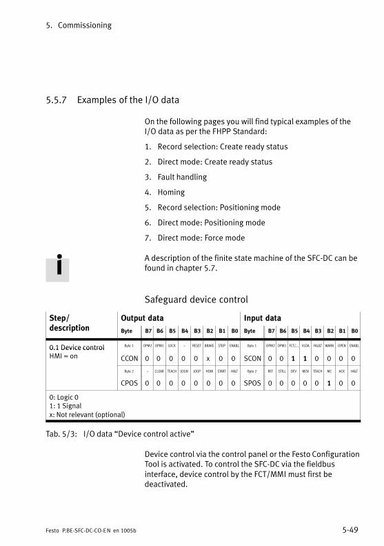
5. Commissioning
5−49Festo P.BE−SFC−DC−CO−EN en 1005b
5.5.7 Examples of the I/O data
On the following pages you will find typical examples of theI/O data as per the FHPP Standard:
1. Record selection: Create ready status
2. Direct mode: Create ready status
3. Fault handling
4. Homing
5. Record selection: Positioning mode
6. Direct mode: Positioning mode
7. Direct mode: Force mode
A description of the finite state machine of the SFC−DC can befound in chapter 5.7.
Safeguard device control
Step/d i ti
Output data Input datadescription Byte B7 B6 B5 B4 B3 B2 B1 B0 Byte B7 B6 B5 B4 B3 B2 B1 B0
0.1 Device control Byte 1 OPM2 OPM1 LOCK � RESET BRAKE STOP ENABL Byte 1 OPM2 OPM1 FCT/... VLOA FAULT WARN OPEN ENABL0.1 Device controlHMI = on CCON 0 0 0 0 0 x 0 0 SCON 0 0 1 1 0 0 0 0
Byte 2 � CLEAR TEACH JOGN JOGP HOM START HALT Byte 2 REF STILL DEV MOV TEACH MC ACK HALT
CPOS 0 0 0 0 0 0 0 0 SPOS 0 0 0 0 0 1 0 0
0: Logic 01: 1 Signalx: Not relevant (optional)
Tab.�5/3: I/O data �Device control active"
Device control via the control panel or the Festo ConfigurationTool is activated. To control the SFC−DC via the fieldbusinterface, device control by the FCT/MMI must first bedeactivated.

5. Commissioning
5−50 Festo P.BE−SFC−DC−CO−EN en 1005b
1. Record selection: Create ready status
1.1 Basic status of the drive when the supply voltage hasbeen switched on.} Step 1.2 or 1.3
1.2 Disable device control by FCT/MMI.Optionally, assuming of device control by the FCT/MMIcan be disabled with CCON.B5 = 1 (LOCK).} Step 1.3
1.3 Enable drive (Record select)} Homing: Example 4, Tab.�5/7
Step/d i ti
Output data Input datadescription Byte B7 B6 B5 B4 B3 B2 B1 B0 Byte B7 B6 B5 B4 B3 B2 B1 B0
1.1 Basic status Byte 1 OPM2 OPM1 LOCK � RESET BRAKE STOP ENABL Byte 1 OPM2 OPM1 FCT/... VLOA FAULT WARN OPEN ENABL1.1 Basic status
(device controlCCON 0 0 0 0 0 x 0 0 SCON 0 0 0 1 0 0 0 0
(device controlHMI�=�off ) Byte 2 � CLEAR TEACH JOGN JOGP HOM START HALT Byte 2 REF STILL DEV MOV TEACH MC ACK HALTHMI�=�off )
CPOS 0 0 0 0 0 0 0 0 SPOS 0 0 0 0 0 1 0 0
1.2 Disable device Byte 1 OPM2 OPM1 LOCK � RESET BRAKE STOP ENABL Byte 1 OPM2 OPM1 FCT/... VLOA FAULT WARN OPEN ENABL1.2 Disable devicecontrol by FCT/MMI CCON x x 1 0 x x x x SCON x x 0 x x x x x
Byte 2 � CLEAR TEACH JOGN JOGP HOM START HALT Byte 2 REF STILL DEV MOV TEACH MC ACK HALT
CPOS 0 x x x x x x x SPOS x x x x x x x x
1.3 Enable drive, Byte 1 OPM2 OPM1 LOCK � RESET BRAKE STOP ENABL Byte 1 OPM2 OPM1 FCT/... VLOA FAULT WARN OPEN ENABL1.3 Enable drive,enable operation CCON 0 0 x 0 0 x 1 1 SCON 0 0 0 1 0 0 1 1
(record selection) Byte 2 � CLEAR TEACH JOGN JOGP HOM START HALT Byte 2 REF STILL DEV MOV TEACH MC ACK HALT(record selection)
CPOS 0 0 0 0 0 0 0 1 SPOS 0 0 0 0 0 1 0 1
0: Logic 01: 1 Signalx: Not relevant (optional)
Tab.�5/4: I/O data �Record selection: Establish readiness to operate"
If there are faults after switching on or after setting CCON.B0(ENABLE):} Fault handling: see example 3, Tab.�5/6

5. Commissioning
5−51Festo P.BE−SFC−DC−CO−EN en 1005b
2. Direct mode: Create ready status
2.1 Basic status of the drive when the supply voltage hasbeen switched on.} Step 2.2 or 2.3
2.2 Disable device control by FCT/MMI.Optionally, assuming of device control by the FCT/MMIcan be disabled with CCON.B5 = 1 (LOCK).} Step 2.3
2.3 Enable drive. (Direct mode)} Homing: Example 4, Tab.�5/7
Step/d i ti
Output data Input datadescription Byte B7 B6 B5 B4 B3 B2 B1 B0 Byte B7 B6 B5 B4 B3 B2 B1 B0
2.1 Basic status Byte 1 OPM2 OPM1 LOCK � RESET BRAKE STOP ENABL Byte 1 OPM2 OPM1 FCT/... VLOA FAULT WARN OPEN ENABL2.1 Basic status
(device controlCCON 0 0 0 0 0 x 0 0 SCON 0 0 0 1 0 0 0 0
(device controlHMI�=�off ) Byte 2 � CLEAR TEACH JOGN JOGP HOM START HALT Byte 2 REF STILL DEV MOV TEACH MC ACK HALTHMI�=�off )
CPOS 0 0 0 0 0 0 0 0 SPOS 0 0 0 0 0 1 0 0
2.2 Disable device Byte 1 OPM2 OPM1 LOCK � RESET BRAKE STOP ENABL Byte 1 OPM2 OPM1 FCT/... VLOA FAULT WARN OPEN ENABL2.2 Disable devicecontrol by FCT/MMI CCON x x 1 0 x x x x SCON x x 0 x x x x x
Byte 2 � CLEAR TEACH JOGN JOGP HOM START HALT Byte 2 REF STILL DEV MOV TEACH MC ACK HALT
CPOS 0 x x x x x x x SPOS x x x x x x x x
2.3 Enable drive, Byte 1 OPM2 OPM1 LOCK � RESET BRAKE STOP ENABL Byte 1 OPM2 OPM1 FCT/... VLOA FAULT WARN OPEN ENABL2.3 Enable drive,enable operation CCON 0 1 x 0 0 x 1 1 SCON 0 1 0 1 0 0 1 1
(Direct mode) Byte 2 � CLEAR TEACH JOGN JOGP HOM START HALT Byte 2 REF STILL DEV MOV TEACH MC ACK HALT(Direct mode)
CPOS 0 0 0 0 0 0 0 1 SPOS 0 0 0 0 0 1 0 1
0: Logic 01: 1 Signalx: Not relevant (optional)
Tab.�5/5: Control and status bytes �Create readiness to operate � Direct mode"
If there are malfunctions after switching on or after settingCCON.B0 (ENABLE):} Malfunction handling: see example 3, Tab.�5/6
5. Commissioning
5−52 Festo P.BE−SFC−DC−CO−EN en 1005b
3. Malfunction handling
Description of errors and warnings see chapter 6.5.
3.1 An error is shown with SCON.B3 (FAULT).} Positioning can no longer be undertaken.
3.2 A warning is shown with SCON.B2 (WARN).} Positioning can still be undertaken.
3.3 Acknowledge fault with positive edge at CCON.B3(RESET).
} Fault bit SCON.B3 (FAULT) or SCON.B2 (WARN) isreset.
} SPOS.B2 (MC) will be set.
} Drive is ready to operate.
3.4 Quit fault with negative edge at CCON.B0 (ENABLE).
} Fault bit SCON.B3 (FAULT) or SCON.B2 (WARN) isreset.
} SPOS.B2 (MC) will be set.
} Establish readiness to operate again(see examples 1, Tab.�5/4 and 2, Tab.�5/5)

5. Commissioning
5−53Festo P.BE−SFC−DC−CO−EN en 1005b
Step/d i ti
Output data Input datadescription Byte B7 B6 B5 B4 B3 B2 B1 B0 Byte B7 B6 B5 B4 B3 B2 B1 B0
3.1 Error Byte 1 OPM2 OPM1 LOCK � RESET BRAKE STOP ENABL Byte 1 OPM2 OPM1 FCT/... VLOA FAULT WARN OPEN ENABL3.1 Error
CCON x x x 0 x x x x SCON x x x x 1 x x x
Byte 2 � CLEAR TEACH JOGN JOGP HOM START HALT Byte 2 REF STILL DEV MOV TEACH MC ACK HALT
CPOS 0 x x x x x x x SPOS x x x x x 0 x x
3.2 Warning Byte 1 OPM2 OPM1 LOCK � RESET BRAKE STOP ENABL Byte 1 OPM2 OPM1 FCT/... VLOA FAULT WARN OPEN ENABL3.2 Warning
CCON x x x 0 x x x x SCON x x x x x 1 x x
Byte 2 � CLEAR TEACH JOGN JOGP HOM START HALT Byte 2 REF STILL DEV MOV TEACH MC ACK HALT
CPOS 0 x x x x x x x SPOS x x x x x 0 x x
3.3 Acknowledge Byte 1 OPM2 OPM1 LOCK � RESET BRAKE STOP ENABL Byte 1 OPM2 OPM1 FCT/... VLOA FAULT WARN OPEN ENABL3.3 Acknowledgefault CCON 0 x x 0 F x x 1 SCON 0 x 0 1 0 0 0 0
with CCON.B3 Byte 2 � CLEAR TEACH JOGN JOGP HOM START HALT Byte 2 REF STILL DEV MOV TEACH MC ACK HALTwith CCON.B3 (RESET) CPOS 0 0 0 0 0 0 x x SPOS x 0 0 0 0 1 0 1
3.4 Acknowledge Byte 1 OPM2 OPM1 LOCK � RESET BRAKE STOP ENABL Byte 1 OPM2 OPM1 FCT/... VLOA FAULT WARN OPEN ENABL3.4 Acknowledgefault CCON 0 x x 0 0 x x N SCON 0 x 0 1 0 0 x 0
with CCON.B0 Byte 2 � CLEAR TEACH JOGN JOGP HOM START HALT Byte 2 REF STILL DEV MOV TEACH MC ACK HALTwith CCON.B0 (ENABLE) CPOS 0 0 0 0 0 0 x x SPOS x 0 0 0 0 1 x x
0: Logic 01: 1 Signalx: Not relevant (optional)F: Positive edgeN: Negative edge
Tab.�5/6: I/O data �Fault treatment"

5. Commissioning
5−54 Festo P.BE−SFC−DC−CO−EN en 1005b
4.Homing (requires status 1.4 or 1.5)
4.1 A positive edge at CPOS.B2 (HOM, Start homing) startsthe homing. The start is confirmed with SPOS.B1(Quit�Start) as long as CPOS.B2 (HOM) is set.
4.2 Movement of the axis is shown with SPOS.B4(MOV,�Axis moves).
4.3 After a successful homing run, SPOS.B2(MC,�Motion�Complete) and SPOS.B7 (REF) are set.
Step/d i ti
Output data Input datadescription Byte B7 B6 B5 B4 B3 B2 B1 B0 Byte B7 B6 B5 B4 B3 B2 B1 B0
4.1 Start homing Byte 1 OPM2 OPM1 LOCK � RESET BRAKE STOP ENABL Byte 1 OPM2 OPM1 FCT/... VLOA FAULT WARN OPEN ENABL4.1 Start homing
CCON 0 x x 0 0 x 1 1 SCON 0 x 0 1 0 0 1 1
Byte 2 � CLEAR TEACH JOGN JOGP HOM START HALT Byte 2 REF STILL DEV MOV TEACH MC ACK HALT
CPOS 0 0 0 0 0 F 0 1 SPOS 0 0 0 0 0 0 1 1
4.2 Homing is running Byte 1 OPM2 OPM1 LOCK � RESET BRAKE STOP ENABL Byte 1 OPM2 OPM1 FCT/... VLOA FAULT WARN OPEN ENABL4.2 Homing is running
CCON 0 x x 0 0 x 1 1 SCON 0 x 0 1 0 0 1 1
Byte 2 � CLEAR TEACH JOGN JOGP HOM START HALT Byte 2 REF STILL DEV MOV TEACH MC ACK HALT
CPOS 0 0 0 0 0 1 0 1 SPOS 0 0 0 1 0 0 1 1
4.3 Homing is Byte 1 OPM2 OPM1 LOCK � RESET BRAKE STOP ENABL Byte 1 OPM2 OPM1 FCT/... VLOA FAULT WARN OPEN ENABL4.3 Homing isfinished CCON 0 x x 0 0 x 1 1 SCON 0 x 0 1 0 0 1 1
Byte 2 � CLEAR TEACH JOGN JOGP HOM START HALT Byte 2 REF STILL DEV MOV TEACH MC ACK HALT
CPOS 0 0 0 0 0 0 0 1 SPOS 1 0 0 0 0 1 0 1
0: Logic 01: 1 Signalx: Not relevant (optional)F: Positive edge
Tab.�5/7: I/O data �homing"
If there are faults during homing:} Malfunction handling: see example 3, Tab.�5/6

5. Commissioning
5−55Festo P.BE−SFC−DC−CO−EN en 1005b
5. Record selection: Positioning mode(requires�status 1.3/2.3 and 4.)
When the readiness to operate is established and the hominghas been carried out, a positioning job can be started(sequence defined by steps 5.1 � 5.4):
5.1 Preselect record number: Byte 3 of the output data0 = Reference travel1 � 31 = Programmable positioning records
5.2 With CPOS.B1 (START, Start job) the preselectedpositioning job will be started. The start is confirmedwith SPOS.B1 (Quit Start) as long as CPOS.B1 (START)is set.
5.3 Movement of the axis is shown with SPOS.B4(MOV,�Axis moves).
5.4 At the end of the positioning job, SPOS.B2(MC,�Motion�Complete) will be set.
If there are faults during positioning:} Malfunction handling: see example 3, Tab.�5/6
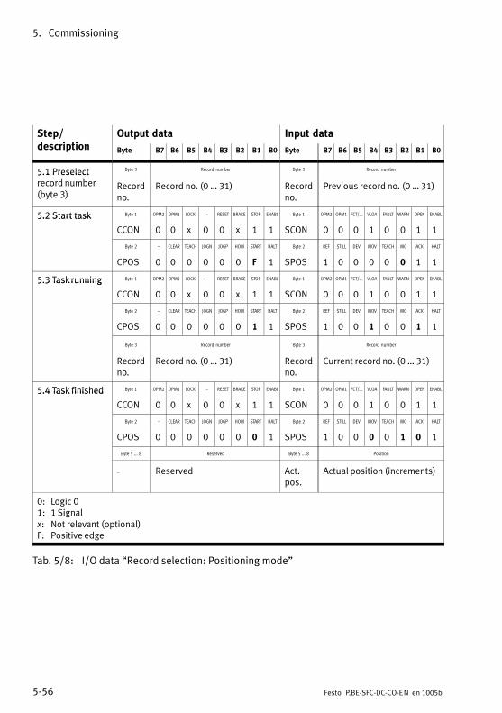
5. Commissioning
5−56 Festo P.BE−SFC−DC−CO−EN en 1005b
Step/d i ti
Output data Input datadescription Byte B7 B6 B5 B4 B3 B2 B1 B0 Byte B7 B6 B5 B4 B3 B2 B1 B0
5.1 Preselect Byte 3 Record number Byte 3 Record number5.1 Preselectrecord number(byte 3)
Recordno.
Record no. (0 � 31) Recordno.
Previous record no. (0 � 31)
5.2 Start task Byte 1 OPM2 OPM1 LOCK � RESET BRAKE STOP ENABL Byte 1 OPM2 OPM1 FCT/... VLOA FAULT WARN OPEN ENABL5.2 Start task
CCON 0 0 x 0 0 x 1 1 SCON 0 0 0 1 0 0 1 1
Byte 2 � CLEAR TEACH JOGN JOGP HOM START HALT Byte 2 REF STILL DEV MOV TEACH MC ACK HALT
CPOS 0 0 0 0 0 0 F 1 SPOS 1 0 0 0 0 0 1 1
5.3 Task running Byte 1 OPM2 OPM1 LOCK � RESET BRAKE STOP ENABL Byte 1 OPM2 OPM1 FCT/... VLOA FAULT WARN OPEN ENABL5.3 Task running
CCON 0 0 x 0 0 x 1 1 SCON 0 0 0 1 0 0 1 1
Byte 2 � CLEAR TEACH JOGN JOGP HOM START HALT Byte 2 REF STILL DEV MOV TEACH MC ACK HALT
CPOS 0 0 0 0 0 0 1 1 SPOS 1 0 0 1 0 0 1 1
Byte 3 Record number Byte 3 Record number
Recordno.
Record no. (0 � 31) Recordno.
Current record no. (0 � 31)
5.4 Task finished Byte 1 OPM2 OPM1 LOCK � RESET BRAKE STOP ENABL Byte 1 OPM2 OPM1 FCT/... VLOA FAULT WARN OPEN ENABL5.4 Task finished
CCON 0 0 x 0 0 x 1 1 SCON 0 0 0 1 0 0 1 1
Byte 2 � CLEAR TEACH JOGN JOGP HOM START HALT Byte 2 REF STILL DEV MOV TEACH MC ACK HALT
CPOS 0 0 0 0 0 0 0 1 SPOS 1 0 0 0 0 1 0 1
Byte 5 ... 8 Reserved Byte 5 ... 8 Position
� Reserved Act.pos.
Actual position (increments)
0: Logic 01: 1 Signalx: Not relevant (optional)F: Positive edge
Tab.�5/8: I/O data �Record selection: Positioning mode"

5. Commissioning
5−57Festo P.BE−SFC−DC−CO−EN en 1005b
6. Direct mode: Positioning mode(requires�status�1.3/2.3 and 4.)
When the readiness to operate is established and the hominghas been carried out, a setpoint position must be preselected(sequence defined by steps 6.1 � 6.4)
6.1 The setpoint position is transferred in increments inbytes 5 � 8 of the output word.The nominal speed is transferred in % in byte 3(0�=�no�speed; 100 = max. speed).
6.2 With CPOS.B1 START (Start positioning job) thepreselected positioning job will be started.The�start�is�confirmed with SPOS.B1 (Quit Start) as longas CPOS.B1 (START) is set.
6.3 Movement of the axis is shown with SPOS.B4(MOV,�Axis moves).
6.4 At the end of the positioning job, SPOS.B2(MC,�Motion�Complete) will be set.
If there are faults during positioning:} Malfunction handling: see example 3, Tab.�5/6

5. Commissioning
5−58 Festo P.BE−SFC−DC−CO−EN en 1005b
Step/d i ti
Output data Input datadescription Byte B7 B6 B5 B4 B3 B2 B1 B0 Byte B7 B6 B5 B4 B3 B2 B1 B0
6.1 Preselect Byte 4 Velocity Byte 4 Velocity6.1 Preselectposition and speed (bytes 4 and 5 � 8)
Speed Speed preselection (0 � 100 %)
Speed Speed feedback (0 � 100 %)
Byte 5 ... 8 Position Byte 5 ... 8 Position
Set�pointpos.
Target position (increments), see chapter 5.5.2
Act.pos.
Actual position (increments),see chapter 5.5.2
6.2 Start task Byte 1 OPM2 OPM1 LOCK � RESET BRAKE STOP ENABL Byte 1 OPM2 OPM1 FCT/... VLOA FAULT WARN OPEN ENABL6.2 Start task
CCON 0 1 x 0 0 x 1 1 SCON 0 1 0 1 0 0 1 1
Byte 2 � CLEAR TEACH JOGN JOGP HOM START HALT Byte 2 REF STILL DEV MOV TEACH MC ACK HALT
CPOS 0 0 0 0 0 0 F 1 SPOS 1 0 0 0 0 0 1 1
Byte 3 FUNC FAST XLIM VLIM CONT COM2 COM1 ABS Byte 3 FUNC FAST XLIM VLIM CONT COM2 COM1 ABS
CDIR 0 0 0 0 0 0 0 S SDIR 0 0 0 0 0 0 0 S
6.3. Task running Byte 1 OPM2 OPM1 LOCK � RESET BRAKE STOP ENABL Byte 1 OPM2 OPM1 FCT/... VLOA FAULT WARN OPEN ENABL6.3. Task running
CCON 0 1 x 0 0 x 1 1 SCON 0 1 0 1 0 0 1 1
Byte 2 � CLEAR TEACH JOGN JOGP HOM START HALT Byte 2 REF STILL DEV MOV TEACH MC ACK HALT
CPOS 0 0 0 0 0 0 1 1 SPOS 1 0 0 1 0 0 1 1
6.4 Task finished Byte 1 OPM2 OPM1 LOCK � RESET BRAKE STOP ENABL Byte 1 OPM2 OPM1 FCT/... VLOA FAULT WARN OPEN ENABL6.4 Task finished
CCON 0 1 x 0 0 x 1 1 SCON 0 1 0 1 0 0 1 1
Byte 2 � CLEAR TEACH JOGN JOGP HOM START HALT Byte 2 REF STILL DEV MOV TEACH MC ACK HALT
CPOS 0 0 0 0 0 0 0 1 SPOS 1 0 0 0 0 1 0 1
0: Logic 01: 1 Signalx: Not relevant (optional)F: Positive edgeS: Positioning condition: 0 = absolute
1 = relative
Tab.�5/9: I/O data �Direct mode: Positioning mode"

5. Commissioning
5−59Festo P.BE−SFC−DC−CO−EN en 1005b
7. Direct mode: Force control(requires�status�1.3/2.3 and 4.)
When the readiness to operate is established and the hominghas been carried out, a setpoint must be specified and theforce mode must be prepared (only for axis type gripperHGPLE, GEH).
The resulting force is heavily dependent on the speed used toposition the workpiece (clearance to the workpiece,parametrisation of speed limits).
7.1 Specify the setpoint value in % of the nominal motorcurrent. (Note frictional influences of the connectedaxis).
7.2 Prepare force control Set bit CDIR.B1(COM1,�Control�mode) and if desired set bit CDIR.B5(XLIM, deactivate stroke limit) for the stroke limitation.
7.3 Start the job with CPOS.B1 START. The start isconfirmed with SPOS.B1 (Quit Start) as long asCPOS.B1 (START) is set.
7.4 or 7.5 Depending on whether the setpoint value is reached ornot, the relevant bits in the status will be set.
7.6 The job will be finished automatically when the strokelimit or software end position is reached. Switching ismade again to position control.
7.7 The job can be discontinued by the controller e.g. withCCON.B1 (STOP).
NoteModification of the setpoint value with force mode is onlypossible with a new starting edge when the last specifiedposition (MC) has been reached.
If there are faults during force mode:see example 3, Tab.�5/6 Fault handling.
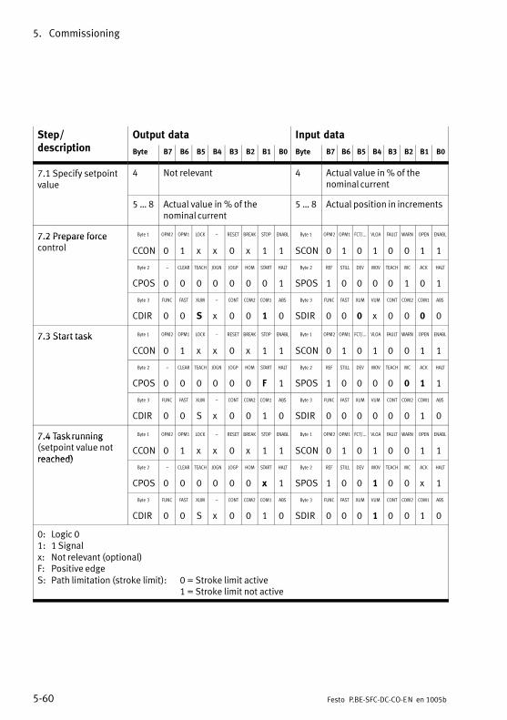
5. Commissioning
5−60 Festo P.BE−SFC−DC−CO−EN en 1005b
Step/d i ti
Output data Input datadescription Byte B7 B6 B5 B4 B3 B2 B1 B0 Byte B7 B6 B5 B4 B3 B2 B1 B0
7.1 Specify setpointvalue
4 Not relevant 4 Actual value in % of thenominal current
5 � 8 Actual value in % of thenominal current
5 � 8 Actual position in increments
7.2 Prepare force Byte 1 OPM2 OPM1 LOCK � RESET BREAK STOP ENABL Byte 1 OPM2 OPM1 FCT/... VLOA FAULT WARN OPEN ENABL7.2 Prepare forcecontrol CCON 0 1 x x 0 x 1 1 SCON 0 1 0 1 0 0 1 1
Byte 2 � CLEAR TEACH JOGN JOGP HOM START HALT Byte 2 REF STILL DEV MOV TEACH MC ACK HALT
CPOS 0 0 0 0 0 0 0 1 SPOS 1 0 0 0 0 1 0 1
Byte 3 FUNC FAST XUM � CONT COM2 COM1 ABS Byte 3 FUNC FAST XUM VUM CONT COM2 COM1 ABS
CDIR 0 0 S x 0 0 1 0 SDIR 0 0 0 x 0 0 0 0
7.3 Start task Byte 1 OPM2 OPM1 LOCK � RESET BREAK STOP ENABL Byte 1 OPM2 OPM1 FCT/... VLOA FAULT WARN OPEN ENABL7.3 Start task
CCON 0 1 x x 0 x 1 1 SCON 0 1 0 1 0 0 1 1
Byte 2 � CLEAR TEACH JOGN JOGP HOM START HALT Byte 2 REF STILL DEV MOV TEACH MC ACK HALT
CPOS 0 0 0 0 0 0 F 1 SPOS 1 0 0 0 0 0 1 1
Byte 3 FUNC FAST XUM � CONT COM2 COM1 ABS Byte 3 FUNC FAST XUM VUM CONT COM2 COM1 ABS
CDIR 0 0 S x 0 0 1 0 SDIR 0 0 0 0 0 0 1 0
7.4 Task running Byte 1 OPM2 OPM1 LOCK � RESET BREAK STOP ENABL Byte 1 OPM2 OPM1 FCT/... VLOA FAULT WARN OPEN ENABL7.4 Task running(setpoint value notreached)
CCON 0 1 x x 0 x 1 1 SCON 0 1 0 1 0 0 1 1reached)
Byte 2 � CLEAR TEACH JOGN JOGP HOM START HALT Byte 2 REF STILL DEV MOV TEACH MC ACK HALT
CPOS 0 0 0 0 0 0 x 1 SPOS 1 0 0 1 0 0 x 1
Byte 3 FUNC FAST XUM � CONT COM2 COM1 ABS Byte 3 FUNC FAST XUM VUM CONT COM2 COM1 ABS
CDIR 0 0 S x 0 0 1 0 SDIR 0 0 0 1 0 0 1 0
0: Logic 01: 1 Signalx: Not relevant (optional)F: Positive edgeS: Path limitation (stroke limit): 0 = Stroke limit active
1 = Stroke limit not active

5. Commissioning
5−61Festo P.BE−SFC−DC−CO−EN en 1005b
Step/description
Input dataOutput dataStep/description B0B1B2B3B4B5B6B7ByteB0B1B2B3B4B5B6B7Byte
7.5 Task running Byte 1 OPM2 OPM1 LOCK � RESET BREAK STOP ENABL Byte 1 OPM2 OPM1 FCT/... VLOA FAULT WARN OPEN ENABL7.5 Task running(setpoint valuereached)
CCON 0 1 x x 0 x 1 1 SCON 0 1 0 1 0 0 1 1reached)
Byte 2 � CLEAR TEACH JOGN JOGP HOM START HALT Byte 2 REF STILL DEV MOV TEACH MC ACK HALT
CPOS 0 0 0 0 0 0 x 1 SPOS 1 0 0 0 0 1 x 1
Byte 3 FUNC FAST XUM � CONT COM2 COM1 ABS Byte 3 FUNC FAST XUM VUM CONT COM2 COM1 ABS
CDIR 0 0 S x 0 0 1 0 SDIR 0 0 0 0 0 0 1 0
7.6 Job discontinued Byte 1 OPM2 OPM1 LOCK � RESET BREAK STOP ENABL Byte 1 OPM2 OPM1 FCT/... VLOA FAULT WARN OPEN ENABL7.6 Job discontinued(stroke limit orsoftware end position
CCON 0 1 x x 0 x 1 1 SCON 0 1 0 1 0 0 1 1software end positionreached) Byte 2 � CLEAR TEACH JOGN JOGP HOM START HALT Byte 2 REF STILL DEV MOV TEACH MC ACK HALTreached)
CPOS 0 0 0 0 0 0 x 1 SPOS 1 0 0 0 0 1 x 1
Byte 3 FUNC FAST XUM � CONT COM2 COM1 ABS Byte 3 FUNC FAST XUM VUM CONT COM2 COM1 ABS
CDIR 0 0 S x 0 0 1 0 SDIR 0 0 1 0 0 0 0 0
7.7 Stop job Byte 1 OPM2 OPM1 LOCK � RESET BREAK STOP ENABL Byte 1 OPM2 OPM1 FCT/... VLOA FAULT WARN OPEN ENABL7.7 Stop job(e.g.�with STOP) CCON 0 1 x x 0 x 0 1 SCON 0 1 0 1 0 0 0 1
Byte 2 � CLEAR TEACH JOGN JOGP HOM START HALT Byte 2 REF STILL DEV MOV TEACH MC ACK HALT
CPOS 0 0 0 0 0 0 x 1 SPOS 1 0 0 0 0 1 x 1
Byte 3 FUNC FAST XUM � CONT COM2 COM1 ABS Byte 3 FUNC FAST XUM VUM CONT COM2 COM1 ABS
CDIR 0 0 S x 0 0 1 0 SDIR 0 0 0 0 0 0 0 0
0: Logic 01: 1 Signalx: Not relevant (optional)F: Positive edgeS: Path limitation (stroke limit): 0 = Stroke limit active
1 = Stroke limit not active
Tab.�5/10: I/O data Direct mode: Force mode

5. Commissioning
5−62 Festo P.BE−SFC−DC−CO−EN en 1005b
5.6 Sequence control as per FHPP standard
5.6.1 Homing
Information on homing, reference coordinates and calculationrules for the reference system are provided in chapter 1.6.
In the case of electric drives with the SFC−DC, after theoperating voltage is switched on, it is a requirement that ahoming run is completed before a positioning job can becarried out (the parameter �homing required" � PNU 1014 �must = 1).
The drive homes against a stop or a reference switch.An�increase in the motor current indicates that a stop hasbeen reached. As the drive must not continuously referenceagainst the stop, it must move at least one millimetre backinto the stroke range.
Sequence:
1. Search for the reference point in accordance with theconfigured method.
2. Move relative to the reference point around the�Offset�axis zero point".
3. Set at axis zero point: Current position = 0 � project zero offset.

5. Commissioning
5−63Festo P.BE−SFC−DC−CO−EN en 1005b
Overview of parameters involved (see also appendix B.2.15)
Parameters involved Description FCT PNU CI
Axis zero point offset x 1010 607Ch
Homing method (permitted: 7, 11, −18, −17) x 1011 6098h
Homing speeds x 1012 6099h
Reference travel required � 1014 23F6h
Homing maximum torque x 1015 23F7h
Start (FHPP) CPOS.B2 = positive edge: Start homing
Acknowledgement(FHPP)
SPOS.B1 = positive edge: Acknowledge startSPOS.B7 = drive referenced
Prerequisites Device control by PLC/field busController must be in status �Operation enabled"There must not be any command for jogging
Tab.�5/11: Parameters involved in homing
Homing methods 1)
Hex Dec Description
07h 7 Search for reference switch in positive direction. The reference position liesat the first index pulse in the negative direction; the reference switchsupplies a 0−signal.
0Bh 11 Search for reference switch in negative direction. The reference positionlies at the first index pulse in the positive direction; the reference switchsupplies a 0−signal.
EFh −17 Search for negative stop. The point found is the reference position. As theaxis must not stand still at the stop, the offset axis zero point must be ≠ 0.
EEh −18 Search for positive stop. The point found is the reference position. As theaxis must not stand still at the stop, the offset axis zero point must be ≠ 0.
1) Detailed description of the homing methods see chapter 5.2.2.
Tab.�5/12: Overview of homing methods

5. Commissioning
5−64 Festo P.BE−SFC−DC−CO−EN en 1005b
5.6.2 Jog mode
In the status �Operation enabled" the drive can be moved tothe left/right by jogging. This function is usually used for:
� Moving to teach positions.
� Moving the drive out of the way (e.g. after a system fault).
� Manual motion as a normal operating mode (manual feed).
Sequence
1. When one of the signals �Jog left / Jog right" is set,the�drive starts to move slowly. Due to the slow speed,a�position can be defined very accurately.
2. If the signal remains set for longer than the configured�phase 1 duration", the speed is increased until theconfigured maximum speed is reached. In this way largestrokes can be traversed quickly
3. If the signal changes to 0, the drive is braked with thepre−set maximum deceleration.
4. The drive stops automatically if it reaches a software endposition. The software end position is not exceeded,the�path for stopping depends on the ramp set.The�jog�mode can be exited here with Jogging = 0.

5. Commissioning
5−65Festo P.BE−SFC−DC−CO−EN en 1005b
1 Low speed phase 1 (slow travel)
2 Maximum speed forphase 2
3 Acceleration
4 Delay
5 Time durationphase�1
CPOS.B3 orCPOS.B4 (Jogging positive/negative)
Speed v(t)
t [s]
1
0
1
2
34
5
Fig.�5/2: Sequence diagram for jog mode
Overview of parameters involved (see appendix B.2.9)
Parametersinvolved
Description FCT PNU CIinvolved
Jog mode speed phase 2 in speed unit (inc/s) x 531 20ED/21
Jog mode acceleration in acceleration unit (inc/s2) x 532 20EE/21
Jog mode deceleration in deceleration unit (inc/s2) x 533 20EF/21
Jog mode duration phase 1 (T1) in ms x 534 20E9/21
Start (FHPP) CPOS.B3 = Positive edge: Jog positive (forwards)CPOS.B4 = Positive edge: Jog negative (backwards)
Acknowledgement(FHPP)
SPOS.B4 = 1: Drive movingSPOS.B2 = 0: (Motion Complete)
Prerequisites Device control by PLC/field busController must be in status �Operation enabled"
Tab.�5/13: Parameters involved in jogging mode

5. Commissioning
5−66 Festo P.BE−SFC−DC−CO−EN en 1005b
5.6.3 Teaching via field bus
Position values can be taught via the fieldbus.Previously�taught position values will then be overwritten.
Sequence
1. The drive will be moved to the desired position by thejogging mode or manually. This can be accomplished injog mode by positioning or by moving by hand in thestatus �Drive blocked".
2. The user must make sure that the desired parameter isselected. For this the parameter �Teach target" and,if�applicable, the correct record address must be entered.
Teach target(PNU�520)
Is taught
= 1 (specification) Setpoint position in the positioningrecord.� Record selection:
Positioning record after controlbyte�3
� Direct mode: Positioning record after PNU = 400
= 2 Axis zero point
= 3 Project zero point
= 4 Lower software end position
= 5 Upper software end position
Tab.�5/14: Overview of teach targets
3. Teaching takes place via the handshake of the bits in thecontrol and status bytes CPOS/SPOS:

5. Commissioning
5−67Festo P.BE−SFC−DC−CO−EN en 1005b
1 Ready for teaching
2 Value transferred
1
0
QuitSPOS.B3
Teach valueCPOS.B5
1 2
1
0
Fig.�5/3: Handshake during teaching
Note: The drive must not stand still for teaching. However, a speedof 1 m/s means that the actual position changes by 1 mmevery millisecond. With the usual cycle times of the PLC +fieldbus + motor controller there will be inaccuracies ofseveral millimetres even at a speed of only 100 mm/s.
Overview of parameters involved (see appendix B.2.8 and B.2.9)
Parameters involved Description FCT PNU CI
Teach target � 1) 520 21FEh
Record number � 1) 400 2190h
Start (FHPP) SPOS.B5 = falling edge: Teach value
Acknowledgement(FHPP)
SPOS.B2 = 1: Value transferred
Prerequisites Device control by PLC/field busController must be in status �Operation enabled"
1) Teaching is made possible in the Festo Configuration Tool by means of special functions.
Tab.�5/15: Teach parameters involved

5. Commissioning
5−68 Festo P.BE−SFC−DC−CO−EN en 1005b
5.6.4 Record selection (positioning mode)
A record can be started in the status �Drive enabled".This�function is usually used for:
� moving to any position in the record list by the PLC,
� processing a positioning profile by linking records
� known target positions that seldom change(recipe�change).
Sequence
1. Set the desired record number in the output data of themaster. Until the start, the controller replies with thenumber of the record last processed.
2. With a rising edge at START (CPOS.B1) the controlleraccepts the record number and starts the positioning job.
3. The controller signals with the rising edge at Quit Startthat the PLC output data has been accepted and that thepositioning job is now active. The positioning commandwill be processed irrespective of whether Start (CPOS.B1)has been reset to zero or not.
4. When the record is concluded, MC (SPOS.B2) is set.
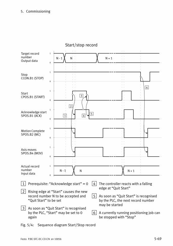
5. Commissioning
5−69Festo P.BE−SFC−DC−CO−EN en 1005b
Start/stop record
Target recordnumber Output data
StopCCON.B1 (STOP)
Acknowledge startSPOS.B1 (ACK)
Motion CompleteSPOS.B2 (MC)
Actual recordnumberInput data
N − 1 N N + 1
N − 1 N
1
0
1
0
1
0
1
0
1
0
1
2
3
4
6
1
0
1
0
Axis movesSPOS.B4 (MOV)
StartCPOS.B1 (START)
N + 1
5
1 Prerequisite: �Acknowledge start" = 0
2 Rising edge at �Start" causes the newrecord number N to be accepted and�Quit Start" to be set
3 As soon as �Quit Start" is recognisedby the PLC, �Start" may be set to 0again
4 The controller reacts with a fallingedge at �Quit Start"
5 As soon as �Quit Start" is recognisedby the PLC, the next record numbermay be started
6 A currently running positioning job canbe stopped with �Stop"
Fig.�5/4: Sequence diagram Start/Stop record

5. Commissioning
5−70 Festo P.BE−SFC−DC−CO−EN en 1005b
Stop record with Hold and continue
Target recordnumber Output data
Acknowledge startSPOS.B1 (ACK)
Motion CompleteSPOS.B2 (MC)
Actual recordnumberInput data
N − 1 N N + 1
N − 1 N
1
0
1
0
1
0
1
0
1
0
1
0
Axis movesSPOS.B4 (MC)
HaltCPOS.B0 (HALT)
1
0
StartCPOS.B1 (START)
1
0
Confirm HaltSPOS.B0 (HALT)
1
2
1 Record is stopped with �Halt," actualrecord number N is retained,�Motion�Complete" remains reset
2 Rising edge at �Start" starts record Nagain, �Confirm Halt" is set
Fig.�5/5: Sequence diagram for Stop record with Halt and Continue
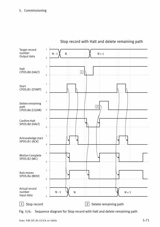
5. Commissioning
5−71Festo P.BE−SFC−DC−CO−EN en 1005b
Stop record with Halt and delete remaining path
Target recordnumber Output data
Acknowledge startSPOS.B1 (ACK)
Motion CompleteSPOS.B2 (MC)
Actual recordnumberInput data
N − 1 N N + 1
N − 1 N
1
0
1
0
1
0
1
0
1
0
1
0
Axis movesSPOS.B4 (MOV)
HaltCPOS.B0 (HALT)
N + 1
1
0
StartCPOS.B1 (START)
Delete remainingpathCPOS.B6 (CLEAR)
1
0
1
0
Confirm HaltSPOS.B0 (HALT)
1
2
1 Stop record 2 Delete remaining path
Fig.�5/6: Sequence diagram for Stop record with Halt and delete remaining path

5. Commissioning
5−72 Festo P.BE−SFC−DC−CO−EN en 1005b
Record structure
A positioning task in record select mode is described by arecord made up of setpoint values. Every setpoint value isaddressed by its own PNU. A record consists of the setpointvalues with the same subindex.
Causes of errors in application:
� Referencing has not been carried out.
� The target position and/or the preselect position cannotbe reached.
� Invalid record number.
� Record not initialised.
Overview of parameters involved (see appendix B.2.8)
Parameters involved Description FCT PNU CI
Record control byte 1 x 401 20EAh
Positioning record target position x 404 20ECh
Record velocity x 406 20EDh
Positioning record acceleration x 407 20EEh
Positioning record deceleration x 408 20EFh
Start (FHPP) CPOS.B1 = positive edge: StartJogging and referencing have priority.
Acknowledgement(FHPP)
SPOS.B2 = 0: Motion CompleteSPOS.B1 = positive edge: Acknowledge startSPOS.B4 = 1: Drive moving
Prerequisites Device control by PLC/field busController must be in status �Operation enabled"Record number must be valid
Tab.�5/16: Record selection parameters involved

5. Commissioning
5−73Festo P.BE−SFC−DC−CO−EN en 1005b
5.6.5 Direct mode (positioning mode, power operation)
Positioning mode
In the status �Operation enabled" (Direct mode) a positioningjob is formulated directly in the I/O data which aretransmitted via the Fieldbus. The setpoint values for theposition are therefore held in the PLC. The function is used inthe following situations:
� Moving to any position within the work stroke.
� The target positions are unknown during planning orchange frequently (several different work item positions).
A positioning profile formed by linking records can beimplemented externally controlled by the master.
Sequence of discrete setpoint value
1. Set the desired setpoint (position) and the positioningconditions (absolute/relative) in the output data.
2. With a rising edge at START (CPOS.B1) the controlleraccepts the setpoint position and starts the positioningjob.
3. After the start you must wait for MC before a new startcan be made.
4. When the setpoint position is reached, MC (SPOS.B2) isset.

5. Commissioning
5−74 Festo P.BE−SFC−DC−CO−EN en 1005b
Starting the positioning job
Setpoint position Output data
StartCPOS.B1
Acknowledge startSPOS.B1
Motion CompleteSPOS.B2
N − 1 N N + 1
1
0
1
0
1
0
1
0
N + 2
Fig.�5/7: Start the positioning task
The sequence of the remaining control and status bits as wellas the functions Hold and Stop react as with the functionRecord select, see Fig.�5/4, Fig.�5/5 and Fig.�5/6.
Causes of errors in application
� No referencing carried out.
� Target position cannot be reached or lies outside thesoftware end positions.

5. Commissioning
5−75Festo P.BE−SFC−DC−CO−EN en 1005b
Overview of parameters involved (see appendix B.2.9)
Parameters involved Description FCT PNU CI
Position specifications Max. permitted speed 1) x 502 21F6/00h
Direct mode acceleration in acceleration unit(inc/s2)
x 541 20EE/22h
Direct mode deceleration in deceleration unit(inc/s2)
x 542 20EE/22h
Start (FHPP) CPOS.B1 = positive edge: Start(CDIR.B0 = setpoint position absolute/relative)
Acknowledgement(FHPP)
SPOS.B2 = 0: Motion CompleteSPOS.B1 = positive edge: Acknowledge startSPOS.B4 = 1: Drive moving
Prerequisites Device control by PLC/field busController must be in status �Operation enabled"
1) In the control bytes the master transfers a percent value which is multiplied by the maximumpermitted speed, in order to achieve the final nominal speed.
Tab.�5/17: Parameters involved in Direct mode (positioning mode)
Force control
Force mode is used in the following situations:(only for axis type gripper HGPLE, GEH, supported fromFW�V2.00):
� For clamping and holding workpieces as well as forprocedures in which work items must be orientated(e.g.�to a fixed stop).
� Pressing and inserting procedures.
� Special functions in which e.g. workpieces must betouched in order to receive position values.

5. Commissioning
5−76 Festo P.BE−SFC−DC−CO−EN en 1005b
Notes on force controlControl of the motor torque takes place indirectly bymeans of the current regulation. All specifications onforces/torques refer to the nominal motor current(relative�to the rated motor torque ). The actual force at theaxis should be calculated/checked and then set withexternal measuring devices during commissioning.
Not that the gripper force resulting from the motor currentis also heavily dependent on the positioning speed used tomove to the workpiece.
NoteThe following settings are required for parametrising theforce mode (see Tab.�5/18):
� Force window (permitted deviation from the setpointvalue ascertained by the Fieldbus).
� Speed limitation (maximum speed that the drive shouldreach).
� Rest time (time during which the setpoint force must beapplied, before �Motion Complete" is triggered).
· Extend the rest time if the setpoint force is alreadyachieved briefly due to the increased torque whenstarting (before reaching the work item).
Force control is prepared when the control mode is switchedover. The drive stands with the position controlled.

5. Commissioning
5−77Festo P.BE−SFC−DC−CO−EN en 1005b
Sequence
1. Set the desired setpoint (in % of nominal motor torque) inthe output data.
2. With the rising edge at Start (CPOS.B1) the controlleraccepts the setpoint torque and builds up theforce/torque in the direction of the sign of the setpointvalue.
� When this speed has been reached, the bit�Speed�limit reached" is set (status byte SDIR).
� When the setpoint value has been reached, taking intoaccount the target window and the time window,the��MC" signal is set. The motor current will still becontrolled.
� If there is a resistance e.g. from a workpiece in thepositioning range, the drive will press against theobstruction with a defined force (see Fig.�5/8).
� If the path set in the path/stroke monitoring(relative�to the starting position) is exceeded, the bit�Stroke limit reached" is set in the status byte SDIR.The drive is braked with the emergency stop ramp,held with the position controlled at the currentposition, and the �MC signal" is set.
Recommendation: Procedure for gripping a workpiece quicklyand with good repeatability of the force:
1. Position just before the workpiece.
2. Switch from positioning mode to force mode.
3. Grip the workpiece is force mode.
Causes of errors
� No referencing carried out.
� Axis stands at the software end position at the start of thepositioning job.
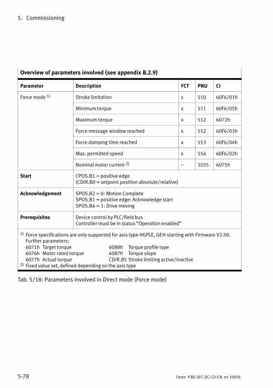
5. Commissioning
5−78 Festo P.BE−SFC−DC−CO−EN en 1005b
Overview of parameters involved (see appendix B.2.9)
Parameter Description FCT PNU CI
Force mode 1) Stroke limitation x 510 60F6/01h
Minimum torque x 511 60F6/05h
Maximum torque x 512 6072h
Force message window reached x 552 60F6/03h
Force damping time reached x 553 60F6/04h
Max. permitted speed x 554 60F6/02h
Nominal motor current 2) � 1035 6075h
Start CPOS.B1 = positive edge(CDIR.B0 = setpoint position absolute/relative)
Acknowledgement SPOS.B2 = 0: Motion CompleteSPOS.B1 = positive edge: Acknowledge startSPOS.B4 = 1: Drive moving
Prerequisites Device control by PLC/field busController must be in status �Operation enabled"
1) Force specifications are only supported for axis type HGPLE, GEH starting with Firmware V2.00.Further parameters:6071h Target torque 6088h Torque profile type6076h Motor rated torque 6087h Torque slope6077h Actual torque CDIR.B5 Stroke limiting active/inactive
2) Fixed value set, defined depending on the axis type
Tab.�5/18: Parameters involved in Direct mode (Force mode)

5. Commissioning
5−79Festo P.BE−SFC−DC−CO−EN en 1005b
Start the positioning job / force mode
ÏÏÏÏÏÏÏÏÏÏÏÏÏÏÏÏÏÏÏÏÏÏÏÏÏÏÏÏÏÏ
Setpoint torqueSpeed limitation Output data
StartCPOS.B1
Acknowledge startSPOS.B1 (ACK)
Motion CompleteSPOS.B2 (MC)
N − 1 N N + 1
1
0
1
0
1
0
1
0
1
0
Axis movesSPOS.B4 (MOV)
1
2 3 4
1 Nominal torque / power reached 2 Axis presses against resistance
3 Resistance removed / overcome 4 Software end position / strokelimitation reached
Fig.�5/8: Start the positioning job / force mode
The signal �MC" (Motion Complete) is used in this controlmode to mean �Nominal value/stroke limitation reached".The sequence of the remaining control and status bits as wellas the functions Hold and Stop behave in the same way as theRecord selection function, see Fig.�5/4, Fig.�5/5 and Fig.�5/6.

5. Commissioning
5−80 Festo P.BE−SFC−DC−CO−EN en 1005b
5.6.6 Standstill monitoring
With the standstill monitoring it is clear that the targetposition window is exited at a standstill.
When the target position has been reached and MC signalledin the status word, the drive switches to the �standstill" state,bit SPOS.B6 (standstill monitor) is reset. If, in this status,the�drive is removed from the standstill position window for aminimum defined time due to external forces or otherinfluences, the bit SPOS.B6 will be set.
As soon as the drive is in the standstill position window againfor the standstill monitoring time, the bit SPOS.B6 will bereset.
1 Target position
2 Actual position
3 Standstill monitoring(SPOS.B6)
4 Motion Complete(SPOS.B2)
5 Standstill positionwindow
6 Target positionwindow
7 Adjustment/Damping time (Position windowtime/Damping time)
8 Standstillmonitoring time
1
0
1
0
1
2
3
4
5 6
7
88
Fig.�5/9: Standstill monitoring

5. Commissioning
5−81Festo P.BE−SFC−DC−CO−EN en 1005b
The standstill monitoring cannot be switched on or offexplicitly. It becomes inactive when the standstill positionwindow is set to �0".
Overview of parameters involved (see appendix B.2.15)
Parameters involved Description FCT PNU CI
Setpoint position � 1040 6062h
Current position � 1041 6064h
Standstill message window � 1042 2040h 1)
Standstill delay time � 1043 2041h 1)
Adjustment time (Positioning mode) � 1023 6068h
Start (FHPP) SPOS.B2 = positive edge: Motion Complete
Acknowledgement(FHPP)
SPOS.B6 = 1: Drive has moved out of standstill position window
Prerequisites Device control by PLC/field busController must be in status �Operation enabled"
1) Starting at firmware version V1.38, earlier versions CI 6065h / 6066h
Tab.�5/19: Parameters involved in standstill monitoring
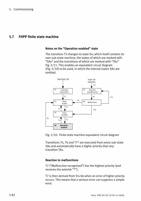
5. Commissioning
5−82 Festo P.BE−SFC−DC−CO−EN en 1005b
5.7 FHPP finite state machine
Notes on the �Operation enabled" state
The transition T3 changes to state S4, which itself contains itsown sub−state machine, the states of which are marked with�SAx" and the transitions of which are marked with �TAx"Fig.�5/11. This enables an equivalent circuit diagram(Fig.�5/10) to be used, in which the internal states SAx areomitted.
Switched off
S1 Controller switched on
S4 Driveenabled
S2 Drivelocked
S5 Reaction to malfunction
S6 Malfunction
From allstatuses
Operationenabled
T6
T2T5
T3T4
T1
T7*
T8
T10
T9
S5
T11
S4
Fig.�5/10: Finite state machine equivalent circuit diagram
Transitions T4, T6 and T7* are executed from every sub−stateSAx and automatically have a higher priority than anytransition TAx.
Reaction to malfunctions
T7 ("Malfunction recognised") has the highest priority (andreceives the asterisk �*").
T7 is then derived from S5+S6 when an error of higher priorityoccurs. This means that a serious error can suppress a simpleerror.

5. Commissioning
5−83Festo P.BE−SFC−DC−CO−EN en 1005b
T7* always has thehighest priority.
Switched off
S1
Controller switched on
S4
Driveenabled
S2
Drivelocked
SA1
Ready
SA5
Jogpositive
SA6
Jognegative
SA4
Homing is executed
SA2
Positioning jobactive
SA3
Intermediate stop
S5
Reaction to malfunction
S6
Malfunction
From allstatuses
S4
Operation enabled
T6
TA11
TA12
TA9
TA10
TA3
TA6
TA4
TA5
TA7
TA8
TA1TA2
T2T5
T3T4
T1
T7*
T8
T10
T9
S5
T11
Fig.�5/11: Finite state machine

5. Commissioning
5−84 Festo P.BE−SFC−DC−CO−EN en 1005b
5.7.1 Create ready status
T Internal conditions Actions of the user
T1 Drive is switched on.An error cannot be ascertained.
T2 Load voltage applied.Fieldbus master must be higher−order controller.
�Enable drive" = 1CCON = xxx0.xxx1
T3 �Stop" = 1CCON = xxx0.xx11
T4 �Stop" = 0CCON = xxx0.xx01
T5 �Enable drive" = 0CCON = xxx0.xxx0
T6 �Enable drive" = 0CCON = xxx0.xxx0
T7* Malfunction recognised.
T8 Reaction to malfunction completed, drivestopped.
T9 There is no longer a malfunction.It was a serious error.
�Acknowledge malfunction" = 0 } 1CCON = xxx0.Pxxx
T10 There is no longer a malfunction.It was a simple error.
�Acknowledge malfunction" = 0 } 1CCON = xxx0.Pxx1
T11 Malfunction still exists. �Acknowledge malfunction" = 0 } 1CCON = xxx0.Pxx1
Key: P = positive edge, N = negative edge, x = any

5. Commissioning
5−85Festo P.BE−SFC−DC−CO−EN en 1005b
5.7.2 Positioning
Fundamentally, the following applies: Transitions T4, T6 and T7* always have priority.
TA Internal conditions Actions of the user
TA1 Referencing is running. Start positioning task = 0 } 1Halt = 1CCON = xxx0.xx11CPOS = 0xx0.00P1
TA2 Motion Complete = 1The current record is completed. The next recordis not to be carried out automatically
"Halt" status is anyCCON = xxx0.xx11CPOS = 0xxx.xxx0
TA3 Motion Complete = 0 Halt = 1 } 0CCON = xxx0.xx11CPOS = 0xxx.xxx0
TA4 Halt = 1Start positioning task = 0 } 1Clear remaining position = 0CCON = xxx0.xx11CPOS = 00xx.xxP1
TA5 Record selection:� A single record is finished.� The next record is processed automatically.
CCON = xxx0.xx11CPOS = 0xxx.xxx1
Direct mode:� A new positioning task has arrived.
CCON = xxx0.xx11CPOS = 0xxx.xx11
TA6 Clear remaining position = 0 } 1CCON = xxx0.xx11CPOS = 01xx.xxxx
TA7 Start homing = 0 } 1Halt = 1CCON = xxx0.xx11CPOS = 0xx0.0Px1
TA8 Referencing finished or stopped. Only for halt:Halt = 1 } 0CCON = xxx0.xx11CPOS = 0xxx.xxxN
Key: P = positive edge, N = negative edge, x = any

5. Commissioning
5−86 Festo P.BE−SFC−DC−CO−EN en 1005b
TA Actions of the userInternal conditions
TA9 Jog positive = 0 } 1Halt = 1CCON = xxx0.xx11CPOS = 0xx0.Pxx1
TA10 Either� Jog positive = 1 } 0� CCON = xxx0.xx11� CPOS = 0xxx.0xx1or� Halt = 1 } 0� CCON = xxx0.xx11� CPOS = 0xxx.xxxN
TA11 Jog negative = 0 } 1Halt = 1CCON = xxx0.xx11CPOS = 0xxP.xxx1
TA12 Either� Jog negative = 1 } 0� CCON = xxx0.xx11� CPOS = 0xxN.xxx1or� Halt = 1 } 0� CCON = xxx0.xx11� CPOS = 0xxx.xxxN
Key: P = positive edge, N = negative edge, x = any
Special features dependent on operating mode:
Operating mode Notes on specific features
Record selection No restrictions.
Direct mode TA2: The condition that no new record may be processed no longer applies.TA5: A new record can be started at any time.

5. Commissioning
5−87Festo P.BE−SFC−DC−CO−EN en 1005b
5.8 Instructions on operation
Take the following instructions and recommendations intoaccount when programming positioning systems with electricaxes:
Password protection
Protection by means of a password is not set when theproduct is supplied from the factory. In order to preventunauthorized or unintentional overwriting or modification ofparameters in the device, all download and control functionscan be blocked.
· Recommendation:Protect the settings of your axis against undesiredmodifications with a password:
� FCT password protection(8�characters,�see�plug−in�help SFC−DC)
� HMI password protection for SFC−DC−...−H2−...(3�characters, see chapter 4.5).
WarningDanger of injury.
Errors in parametrisation can cause injury to people andmaterial damage. In the following cases reference travel isabsolutely essential in order that the reference coordinatesand the working range can be set correctly:
� when commissioning the first time,
� when the referencing method is changed,
� each time the logic voltage supply is switched on.

5. Commissioning
5−88 Festo P.BE−SFC−DC−CO−EN en 1005b
NoteMake sure that:
� the axis lies within the permitted positioning range whenit is switched on and before the start of a homing run,
� homing is carried out when the higher−order controller ormotor controller is switched on or, if applicable,after�malfunctions
Device connection
CautionThe RS232 interface is not electrically isolated. It is notintended for permanent connection to PC systems, nor as acontrol interface.
· Use the connection only for parametrisation anddiagnosis.
Control during operation
WarningDanger of injury.
Errors in parametrisation can cause injury to people anddamage to property when the controller is enabled.
· Enable the controller only if the axis system has beencorrectly installed and parametrised.
CautionNote the manufacturer’s specifications for the permittedoperating conditions of the motors and drives used,e.g.�in�respect of the permitted positioning speeds.

5. Commissioning
5−89Festo P.BE−SFC−DC−CO−EN en 1005b
CautionDamage to components
Movement to the mechanical end positions is notpermitted during operation. If movement is made to theend positions with a heavy load, jamming may occur in theend positions.
NoteAny functions implemented for the purposes of yourEMERGENCY STOP procedures must be accommodated inthe control programs.
Service and maintenance
The motor units do not require maintenance during theirspecified service life. Follow the maintenance instructions forthe components used.

5. Commissioning
5−90 Festo P.BE−SFC−DC−CO−EN en 1005b

Diagnosis and error treatment
6−1Festo P.BE−SFC−DC−CO−EN en 1005b
Chapter 6

6. Diagnosis and error treatment
6−2 Festo P.BE−SFC−DC−CO−EN en 1005b
Contents
6.1 Diagnostics options 6−3 . . . . . . . . . . . . . . . . . . . . . . . . . . . . . . . . . . . . . . . . . . . . .
6.2 LED status displays 6−4 . . . . . . . . . . . . . . . . . . . . . . . . . . . . . . . . . . . . . . . . . . . . .
6.3 Malfunction messages 6−7 . . . . . . . . . . . . . . . . . . . . . . . . . . . . . . . . . . . . . . . . . . .
6.3.1 Overview 6−7 . . . . . . . . . . . . . . . . . . . . . . . . . . . . . . . . . . . . . . . . . . . . . .
6.3.2 Description of errors and warnings 6−9 . . . . . . . . . . . . . . . . . . . . . . . . .
6.4 Diagnostic memory 6−12 . . . . . . . . . . . . . . . . . . . . . . . . . . . . . . . . . . . . . . . . . . . . .
6.5 Diagnosis via CANopen 6−14 . . . . . . . . . . . . . . . . . . . . . . . . . . . . . . . . . . . . . . . . . .
6.5.1 Node guarding 6−14 . . . . . . . . . . . . . . . . . . . . . . . . . . . . . . . . . . . . . . . . . .
6.5.2 Emergency messages 6−15 . . . . . . . . . . . . . . . . . . . . . . . . . . . . . . . . . . . .
6.5.3 Diagnosis via parameter channel 6−16 . . . . . . . . . . . . . . . . . . . . . . . . . . .

6. Diagnosis and error treatment
6−3Festo P.BE−SFC−DC−CO−EN en 1005b
6.1 Diagnostics options
The SFC−DC offers the following possibilities for diagnosis anderror display:
Diagnosticsoption
Brief description Advantages/Properties
Detaileddescription
LED display LEDs indicate readiness to operate,positioning status, errors and busstatus.
Fast �on−site"error detection.
Chapter 6.2
Control panelwith LC display onSFC DC H2
Warnings, messages and errors aredisplayed directly on the LC display
Fast �on−site"error diagnosis.
Chapter 6.3
SFC−DC−...−H2−...Diagnostic data, operating mode, thecurrent positioning set, target andactual positions, speed as well asinformation on bus communicationcan be accessed on the control panel.
Detaileddiagnosticpossibility�on−site".
Chapter 6.3
FestoConfigurationTool
With active device connection:� Display of the current position set,
target and actual positions as wellas speed.
� Display of the operating mode,special outputs and operatingstates as well as error messages ofthe connected SFC−DC.
� Display of the device status.� Display of the diagnostic memory.� Display of the bus status.
Detailed diagnosisduringcommissioning.
Help on PlugInSFC−DC
CANopen � Emergency Messages.� Nodeguarding.� Diagnosis via FHPP status bytes
SCON and SPOS.
Simple diagnosisvia the field bus.
Chapter 6.5
Parameterchannel
� Extended access to diagnosticdata, e.g. diagnostic memory.
If necessary,detailed diagnosisvia the field bus.
Chapter 6.5.3
Tab.�6/1: Summary of diagnostics options

6. Diagnosis and error treatment
6−4 Festo P.BE−SFC−DC−CO−EN en 1005b
6.2 LED status displays
1 LEDs� Power (green)� I/F (green/red)� Error (red)
1
Fig.�6/1: LEDs of the SFC−DC
The visual display of the operating states is shown via 3 LEDs
� Operating voltage LED (POWER)
� Bus status, positioning status (I/F)
� Error LED (ERROR)

6. Diagnosis and error treatment
6−5Festo P.BE−SFC−DC−CO−EN en 1005b
Operating and logic voltage
Power Status
Logic and load voltage applied.
green
Logic voltage is present.Load voltage is not applied.Check voltage connection if necessary
flashingCheck voltage connection if necessary.
Logic voltage is not present.Check voltage connection if necessary.
off
Tab.�6/2: LED �Power"
Error display
Error Status
� No internal error indicated.The SFC−DC is ready to operate.
off
Error.The SFC−DC is not ready for operation.Check cause and rectify if necessary
redCheck cause and rectify if necessary,see�also�chapter�6.3.
Warning.Check cause and rectify if necessary,see also chapter 6 3
flashingsee�also�chapter�6.3.
Tab.�6/3: LED �Error"
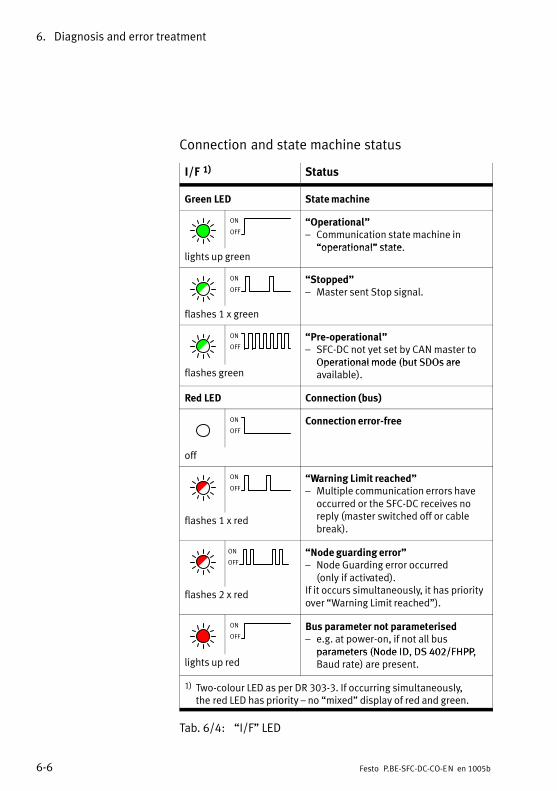
6. Diagnosis and error treatment
6−6 Festo P.BE−SFC−DC−CO−EN en 1005b
Connection and state machine status
I/F 1) Status
Green LED State machine
ON
OFF�Operational"� Communication state machine in
�operational" statelights up green
�operational" state.
ON
OFF
�Stopped"� Master sent Stop signal.
flashes 1 x green
ON
OFF�Pre−operational"� SFC−DC not yet set by CAN master to
Operational mode (but SDOs areflashes green
Operational mode (but SDOs areavailable).
Red LED Connection (bus)
ON
OFFConnection error−free
off
ON
OFF�Warning Limit reached"� Multiple communication errors have
occurred or the SFC−DC receives nol ( i h d ff blflashes 1 x red reply (master switched off or cable
break).
ON
OFF�Node guarding error"� Node Guarding error occurred
(only�if�activated).If i i l l i h i iflashes 2 x red
( y )If it occurs simultaneously, it has priorityover �Warning Limit reached").
ON
OFFBus parameter not parameterised� e.g. at power−on, if not all bus
parameters (Node ID, DS 402/FHPP,lights up red
parameters (Node ID, DS 402/FHPP,Baud rate) are present.
1) Two−colour LED as per DR 303−3. If occurring simultaneously,the�red LED has priority � no �mixed" display of red and green.
Tab.�6/4: �I/F" LED

6. Diagnosis and error treatment
6−7Festo P.BE−SFC−DC−CO−EN en 1005b
6.3 Malfunction messages
6.3.1 Overview
Category Name, display Description Deviceerror 1)
Mal�functionNumber
ErrorLED
Statusbytes 2)
Error POSITION ERROR Following error 0x0001 31 ON FAULT, DEV
Error(message)
MOTOR−STOP Motor stop(Emergencystop)
0x0002 106 ON FAULT
Error HOMING ERROR homing error 0x0004 32 ON FAULT
Error OVERHEATING Overtemperature (ActTemp > 80)
0x0008 101 ON FAULT
Error LOAD−POWER−DOWN
Load voltagemonitoring(undervoltage atthe controller)
0x0010 70 ON FAULT
Error I2t−ERROR Currentmonitoring(i2t�monitoring)
0x0020 100 ON FAULT
Error HARDWARE ERROR Hardware deviceerror (user datadestroyed,check�sum)
0x0040 52 ON FAULT
Error TARGET POSITIONOUT OF LIMIT
Target positioncannot bereached
0x0080 2 ON FAULT
Warning ILLEGAL RECORD Invalid recordnumber
0x0100 3 FLASHES WARN
Error PLEASE ENFORCEHOMING RUN
Reference travelrequired
0x0200 1 ON FAULT
1) see PNU 205 / object 2FF1/002) FHPP status bytes, see chapter 5.5.2

6. Diagnosis and error treatment
6−8 Festo P.BE−SFC−DC−CO−EN en 1005b
Category Statusbytes 2)
ErrorLED
Mal�functionNumber
Deviceerror 1)
DescriptionName, display
Error POSITION PLAUS.ERROR
Positionplausibility error(max. speedexceeded)
0x0400 35 ON FAULT
Error DIGITAL−POWER−DOWN
Logic voltagemonitoring(undervoltage atthe controller)
0x0800 71 ON FAULT
Warning INDEX PULSEWARNING
Index PulseWarning
0x1000 � FLASHES WARN
Error MOTOR ERROR Motor errorPhase failure(no motorcurrent)
0x2000 103 ON FAULT
Warning STANDSTILL Standstillmonitoringwarning
0x4000 36 FLASHES WARN,STILL
Error CAN−BUS INIT NOPARAMETERERROR
CAN bus errorEssential busparameters notset
0x8000 51 ON FAULT
Error CAN−BUS NO EXT.SUPPLY VOLTAGE
CAN bus errorExternal CANpower supplymissing (only ifparametrised,see�chapter 4.5,Tab.�4/21 orobject 2FF6h,appendix�C.3).
0x8000 51 ON FAULT
Warning HOTTEMPERATURE
Overheating � � FLASHES WARN
Warning COLDTEMPERATURE
Undertemperature
� � FLASHES WARN
1) see PNU 205 / object 2FF1/002) FHPP status bytes, see chapter 5.5.2
Tab.�6/5: Errors and warnings with malfunction numbers and error bits

6. Diagnosis and error treatment
6−9Festo P.BE−SFC−DC−CO−EN en 1005b
6.3.2 Description of errors and warnings
Messages The following message is displayed if a positioning procedureis aborted manually or cannot be carried out.
· Acknowledge the message on the control panel with<Enter> or start a new positioning procedure with the FCTor via the control interface.
Message Cause
MOTOR−STOP A positioning procedure has been stopped withthe <Menu> button (EMERG. STOP [Menu] ).
Tab.�6/6: Messages
Warnings[WARNING MODE]
For states that do not prevent functioning, the SFC−DCdisplays a warning. If a positioning task is running, it is notinterrupted. The error LED flashes, the output WARNING(FHPP status bits, SCON.B2) is set.
Warning Cause
COLD TEMPERATURE
Operating temperature T < −10 °C. Increaseambient temperature if necessary.
HOT TEMPERATURE
Operating temperature T > 75 °C, check forpossible overloading of the drive; check themechanical system, e.g.�for sluggishness;reduce ambient temperature.
ILLEGAL RECORD Non−permitted record number. The transmittedrecord number is outside the permissible range.
INDEX PULSEWARNING
During homing: The reference switch signal is too close to theindex pulse. This can in some cases mean thatno reproducible reference position can bedetermined.· Shift the reference switch
(a�few�tenths�of�a�mm).
STANDSTILL The axis has moved outside the standstilltolerance window.
Tab.�6/7: Warnings

6. Diagnosis and error treatment
6−10 Festo P.BE−SFC−DC−CO−EN en 1005b
Error[ERROR−MODE]
If there is an error, the drive will be stopped. The error LEDflashes, the FAULT output (FHPP status bits, SCON.B3) is set.
· Eliminate the cause of the error.
· Acknowledge the error message:
� using <Enter> on the control panel,
� via a falling edge at the RESET input(FHPP�control�bits, CCON.B3),
� via a falling edge at the ENABLE input(FHPP�control�bits, CCON.B0, the axis can move oncethe enable is switched off ),
� with the �Acknowledge error" button in theFesto�Configuration Tool.
Error Possible cause Remedy
CAN−BUS INIT NOPARAMETER ERROR
Essential bus parameters not set.� SFC−DC not on bus.
· Set bus parameters(see�chapter 5.2.8):� CAN Node−ID� CAN Baud rate� CAN Profile
CAN−BUS NO EXT.SUPPLY VOLTAGE
External CAN supply missing (only ifparameterize; see chapter 5.2.8)
· Check external CAN supply(see chapter 3.7) or
· Set internal CAN supply(see�chapter 5.2.8)
DIGITAL−POWER−DOWN
Voltage monitoring.Possible causes:� Digital voltage supply too low� Voltage drops under load
· Check the power supply:� Power supply unit too weak?� Supply line too long?
HARDWARE ERROR Device fault e.g. EEPROM defective. · Please contact your FestoService.
HOMING ERROR Error during the reference run.Possible causes:� Reference switch defective
· If necessary, check thefunctioning of the referenceswitch.
· Make sure homing is repeated.

6. Diagnosis and error treatment
6−11Festo P.BE−SFC−DC−CO−EN en 1005b
Error RemedyPossible cause
I2t−ERROR Current monitoring i2t.Possible causes:� The drive is blocked
· Check the mechanical systemof the drive.
LOAD−POWER−DOWN Voltage monitoring.Possible causes:� Load voltage supply lacking or too low� Voltage drops under load
· Check the power supply:� Power supply unit too weak?� Supply line too long?
MOTOR ERROR Motor not connected or cable fracture. · Check connection to motor,replace cable if necessary.
OVERHEATING Overheating (operating temperature > 80 °C).� Too high temperature in the power
end stage.
· Check:� That the limits are complied
with (motor characteristiccurves)
� The mechanical partse.g.�for�stiffness
· If necessary, reduce theambient temperature.
PLEASE ENFORCEHOMING RUN
When starting a positioning job:� After the power supply was switched
on, no reference run was carried outor a reference run was stopped.
· Carry out a homing run.
POSITION ERROR Position fault (drag fault).Possible causes:� The drive is blocked� sluggish mechanics or too much mass
(acceleration).� The positioning speed is too high.
· Check:� The mechanics of the drive� The speed of the positioning
job
POSITIONPLAUSIBILITY ERROR
Plausibility error.Possible causes:� Actual speed has exceeded the
predefined limit value.
May be possible with verticalmounting and large moving mass.· Reduce:
� The moving mass� The acceleration
TARGET POSITION OUT OF LIMIT
Target position fault� The specified target position is
outside the permitted positioningrange.
· Check the software endpositions and the targetposition.
Tab.�6/8: Error

6. Diagnosis and error treatment
6−12 Festo P.BE−SFC−DC−CO−EN en 1005b
6.4 Diagnostic memory
The diagnostic memory contains the codes of the last16�diagnostic messages and is saved if possible when thepower fails. If the diagnostic memory is full, the oldestelement will be overwritten (FIFO principle).
Structure of the diagnostic memory
Parameters 1) PNU 200/20C8h PNU 201/20C9h PNU 202/20CAh
Format uint8 uint16 uint32
Significance Diagnostic event Fault Number Time
Subindex 1 Latest / current diagnostic message
Subindex 2 Last diagnostic message
... ...
Subindex 16 Oldest diagnostic message
1) PNUs see appendix B.2.6, objects see appendix C.1.3
Tab.�6/9: Structure of diagnostic memory
Configuration of diagnostic memory with PNU 204 / Object 20CCh
SI Description Default Min Max
1 = 1: Record incoming and outgoing 1) faults= 2: Record only incoming faults
1 1 2
2 = 1: Resolution time stamp 10 ms= 2: Resolution time stamp 1 ms
1 1 2
3 Deleting the diagnostic memory� Writing with value = 1 deletes the diagnostic memory� Read will always be answered with value = 0.
0 0 1
4 Number of valid entries in the diagnostic memory. 0 0 16
1) Outgoing fault = time point when the fault was acknowledged.
Tab.�6/10: Structure of diagnostic memory

6. Diagnosis and error treatment
6−13Festo P.BE−SFC−DC−CO−EN en 1005b
The faults are divided into logical groups according to thefault numbers. There are both simple and serious faultswithin a group.
Range Name Comment
0 � No fault active
1 ... 19 Execution error Examples: No homing run, setpoint position outside softwareend positions, setpoint value calculation not possible.Although the system is OK, a user command cannot beprocessed. In most cases there is an error in operation.Source: sequence control, controller
20 ... 29 Parameter fault Example: Software end positions outside the working stroke.A parameter lies within the limit values so that it can bewritten by the user. During the new calculation of thecontroller, it was ascertained that it is not permitted in thecontext of the other parameters.Note: Non−permitted parameters are rejected by theparameter protocol and do not generate a fault in thecontroller
30 ... 49 controller Examples: Positioning timeout, homing run not successful,drag error too large, ...The task could not be processed correctly. No hardware faultis recognised here. Source: controller
50 ... 69 Initialisation Fault in initialising the controller
70 ... 79 Run time of controller Error in controller run time: undervoltage, checksum
80 ... 89 � Reserved
90 ... 99 � Reserved
100 ... 109 Run time of motor Run time of motor: undervoltage, overtemperature, etc.
110 ... 119 � Reserved
Tab.�6/11: Overview of fault numbers
A detailed description of the warnings and malfunctions canbe found in chapter 6.3.
6. Diagnosis and error treatment
6−14 Festo P.BE−SFC−DC−CO−EN en 1005b
6.5 Diagnosis via CANopen
The SFC−DC supports the following diagnostic possibilities viaCANopen:
� FHPP status bytes (see chapter 5.5.2):� SCON.B2: WARN � Warning� SCON.B3: FAULT � Fault� SPOS.B5: DEV � Contouring error� SPOS.B6: STILL � Standstill monitoring.
� Node guarding, if activated (see chapter 6.5.1).
� Emergency messages (see chapter 6.5.2).
6.5.1 Node guarding
Response to bus failure
In order that a CAN bus failure can be detected, nodeguarding must be activated (default: switched off ).
In the case of actuators it is advisable to monitor the masterfor failure in order to provide an appropriate emergencyshutdown strategy.
Then the CANBUS master is monitored based on monitoringof activation with the configured monitoring time(see�DS�301). When monitoring is activated, the configuredemergency stop response (Fault reaction option code object605Eh, PNU 1021) is executed and the drive is stopped.
Select the Guard Time with reference to the dynamics of thesystem.
Refer to your master documentation for details on how toactivate node guarding.

6. Diagnosis and error treatment
6−15Festo P.BE−SFC−DC−CO−EN en 1005b
6.5.2 Emergency messages
Faults, but not warnings, are signalled by emergencymessages as per DS 301 and DS 402, regardless of theconfigured device profile.
Error code Type of fault Fault register
2310 I2t−fault Bit 1
4210 Temperature monitoring Bit 3
5112 Load voltage monitoring Bit 2
5113 Logic voltage monitoring Bit 2
5441 Homing error Bit 5
6310 No Homing: No homingperformed prior to positioningtask
Bit 5
6320 Out of Limit, target positiontoo large/small
Bit 5
7122 Motor emergency stop Bit 5
7600 Hardware fault (EEPROM) Bit 5
8500 Motor fault (currentmonitoring, cable break)
Bit 5
8600 Following error Bit 5
Communications emergency messages as per DS 301 may also besignalled.
Tab.�6/12: Emergency messages

6. Diagnosis and error treatment
6−16 Festo P.BE−SFC−DC−CO−EN en 1005b
6.5.3 Diagnosis via parameter channel
The Festo parameter channel (see appendix B.1.1) offers thefollowing methods of access to diagnostic information(see�PNU 201 to 206, appendix B.2.6):
� Current device fault (compare faults and warningssee�chapter 6.3),
� Diagnostic memory (PNU 200, PNU 201, PNU 202),
� CANopen diagnosis (PNU 206).

Technical appendix
A−1Festo P.BE−SFC−DC−CO−EN en 1005b
Appendix A
A. Technical appendix
A−2 Festo P.BE−SFC−DC−CO−EN en 1005b
Contents
A.1 Technical Data A−3 . . . . . . . . . . . . . . . . . . . . . . . . . . . . . . . . . . . . . . . . . . . . . . . . .
A.2 Accessories A−5 . . . . . . . . . . . . . . . . . . . . . . . . . . . . . . . . . . . . . . . . . . . . . . . . . . . .
A.3 Converting the units of measurement A−7 . . . . . . . . . . . . . . . . . . . . . . . . . . . . . . .

A. Technical appendix
A−3Festo P.BE−SFC−DC−CO−EN en 1005b
A.1 Technical Data
General
Protection class as per EN�60529 (plug connector inserted or fitted withprotective cap)
IP54
Relative air humidity 0 to 95 %, non condensing
Temperature range� Operation� Storage/transport
0�°C ... +40�°C−25�°C ... +60�°C
Protection against electric shock(protection against direct and indirect contactas per IEC/DIN EN 60204−1)
By means of PELV power circuit (Protected�Extra−Low Voltage)
CE symbol (declaration of conformity)è www.festo.com
In accordance with EU EMC Directive 1)
Vibration as per DIN/IEC68/EN�60068 part 2−6:0,35�mm travel at 10 ... 60 Hz5�g acceleration at 60 ... 150�Hz
Shock as per DIN/IEC68/EN�60068 part 2−27:±30�g at 11�ms duration;5 shocks per direction
Temperature monitoring Shut−down at temperature > 80 °C
Display resolution 128 x 64 pixels
Serial interface RS232, 9600 baud
Mounting Wall or DIN H−rail mounting
1) The component is intended for use in industrial environments. In residential areas, measures for radio interference suppression may have to be taken.The maximum permitted I/O signal cable length is 30 m (reference switch).
Mechanical data
Dimensions approx. 126 x 120 x 62 mm
Product weight approx. 0.6 kg

A. Technical appendix
A−4 Festo P.BE−SFC−DC−CO−EN en 1005b
Electrical data
Load voltage supply (power connection, pins A1, A2)� Nominal voltage� Nominal current (motor)� Peak current
See chapter 3.2
24 VDC ± 10 %3 A5 A
Logic voltage supply (power connection, pins 1, 2)� Nominal voltage� Nominal current� Peak current
See chapter 3.2
24 VDC ± 10 %0.1 A0.8 A
Specifications for serial interface See chapter 3.5
Specifications for reference switch input To DIN/EN 61131 part 2 (IEC 1131−2), see chapter 3.6
CANopen data
Design� Physical layer� Data link layer
as per ISO/DIS 11898 (corresponding to DS 102)as per CAN specification 2.0
CAN protocol as per DS 301 and DS 402
Manufacturer ID 29 (0x1D)
Profile ID (device type) Depending on data profile:� DS 402: 131474 (0x00020192)� FHPP: 301 (0x0000012d)
Address range 1 ... 127
Baud rate 20, 50, 100, 125, 250, 500, 800 and 1000 kBaud
Interface� Plug� Galvanic isolation depending on
parametrisation(see�chapters�3.7,�4.5�and�5.2.8)
� Integrated bus termination
D−Sub, 9−pinParameter "CAN Voltage Supply":� Internal: No galvanic isolation (default)� External: Galvanic isolationNo
Cable type Depends on length of cable and fieldbus baudrate, see controller manual or DS 102.

A. Technical appendix
A−5Festo P.BE−SFC−DC−CO−EN en 1005b
A.2 Accessories
Connection Cable/plug Type Length [m]
Power supply Power supply cable KPWR−MC−1−SUB−15HC−... 2.5 / 5 / 10
Motor connection Motor cable KMTR−DC−SUB−15−M12−... 2.5 / 5 / 10
Reference switch e.g. type SME−10.../SMT−10... or extension cable type KM8−M8−...
Serial interface Programming cable KDI−MC−M8−SUB−9−... 2.5
Controller(CANopen�interface)
Fieldbus plug for openfieldbus cable end
FBS−SUB−9−BU−2x5POL−B �
Fieldbus plug for M12adapter
FBA−2−M12−5POL �
Screw terminal adapter,5−pin, IP20
FBA−1−SL−5POL �
Terminal strip for screwterminal adapter
FBSD−KL−2x5pol �
Fieldbus plug IP20 FBS−SUB−9−WS−CO−K �
Protective caps Type Comment
1 protective cap for the serial interface ISK−M8 10 items per bag
1 protective cap for the connection�Reference�switch", if not used
Wall mounting Type Comment
2 sets of central supports (4 brackets) MUP−18/25 2 items per bag
For wall mounting, additionally 4 suitable M3 screws with cylindrical head are required
H−rail mounting
For H−rail mounting, you will require a DIN mounting rail EN 60715 � 35x7.5 or 35x15; width 35 mm,Height 7.5 mm or 15 mm

A. Technical appendix
A−6 Festo P.BE−SFC−DC−CO−EN en 1005b
Manual in paper form
German P.BE−SFC−DC−CO−DE
English P.BE−SFC−DC−CO−EN
French P.BE−SFC−DC−CO−FR
Italian P.BE−SFC−DC−CO−IT
Spanish P.BE−SFC−DC−CO−ES
Swedish P.BE−SFC−DC−CO−SV

A. Technical appendix
A−7Festo P.BE−SFC−DC−CO−EN en 1005b
A.3 Converting the units of measurement
In the SFC−DC all parameters are always saved in incrementspecifications (inc, inc/s, inc/s2) and not converted until theyare written or read. For the display, conversion from theinternal basis system into the (pre)set measuring systemtakes place within the firmware; for representation on the PCmonitor within the FCT software. In this way, the user doesnot need to carry out conversion when entering values orwhen reading on the control panel or in the FCT. The direct transfer of values via the field bus interface or theserial interface with CI commands always takes place in thebasis system and it is assumed that conversion intoincrements has already taken place.
Conversion is carried out via the parameters:
� feed constant, depending on the drive,
� gear reduction,
� encoder resolution = physical measuring steps per motorrevolution.
Parameter SLTE−10 SLTE−16
Feed Feed constant SLTE−...−BS5.0: 5000 [ìm/rot] SLTE−...−LS7.5: 7500 [ìm/rot]
Gear Gear reduction 1) SLTE−...−G04 (57:13)
Enc Encoder resolution 2) 512 x 4 = 2048 [incr/rot] 1,000 x 4 = 4000 [incr/rot]
HGPLE−14 / GEH60 HGPLE−25 / GEH61
Feed Feed constant 31.416 [ìm/rot] 62.832 [ìm/rot]
Gear Gear reduction 1) 385 : 4 84 : 1
Enc Encoder resolution 2) 1,000 x 4 = 4000 [incr/rot] 1,000 x 4 = 4000 [incr/rot]
1) Specification in two natural numbers for numerator or denominator of the fraction2) With the SFC−DC: Pulse quadruplication by digital interpolation
Tab.�A/1: Basic parameters for the system of measurement units for linear drives

A. Technical appendix
A−8 Festo P.BE−SFC−DC−CO−EN en 1005b
Parameter DEF
Feed Feed constant 100.000
Gear Gear reduction 1) 100 : 1
Enc Encoder resolution 2) 500 x 4 = 2000
1) Specification in two natural numbers for numerator or denominator of the fraction2) With the SFC−DC: Pulse quadruplication by digital interpolation
Tab.�A/2: Basic parameter for the system of measurement units for rotary drives
Special conversion factors
Unit of length SLTE−10 SLTE−16 HGPLE−16/GEH60
HGPLE−25/GEH61
Increments > millimetres Increments /1,795.938
Increments /2,338.461
Increments /12.254,901
Increments /5.347,593
Millimetre > increments Millimetres *1,795.938
Millimetres *2,338.461
mm *12.254,901
mm *5.347,593
Increments > inch Increments /45,616.83
Increments /59,396.92
Increments /311.274,48
Increments /135.828,86
Inch > increments Inch *45,616.83
Inch *59,396.92
Inch *311.274,48
Inch *135.828,86
Tab.�A/3: Conversion factors for the system of measurement units for linear drives
Unit DEF
Increments > degrees Increments / 555.555556 (555.555556 = 200,000 / 360)
Degrees > increments Degree * 555.555556 (555.555556 = 200,000 / 360)
Increments > revolutions Increments / 200,000
Revolutions > increments Revolutions * 200,000
Tab.�A/4: Conversion factors for system of measurement units for rotary drives

A. Technical appendix
A−9Festo P.BE−SFC−DC−CO−EN en 1005b
General conversion factors UF
[ìm] > [inc]
[ìinch] > [inc]
[rot] > [inc]
1�[inch]��� � 25, 4�[mm]
1�[minch]��� � 0, 0254�[mm]
1�[°]����� � 1360
� [rot]
UFmm��incmm�� � enc� gearfeedmm
���incrot �rotrot
mmrot
�UFminch�� inc
minch� � enc� gear
feedminch���incrot �
rotrot
minchrot
���������� enc� gear
feedmm � 10,0254
��� incrot �
rotrot
mmrot �
minchmm
���������� UFmm � 0, 0254���incmm� mm
minch�
UFrot��incrot�� � enc� gear���incrot
� rotrot�

A. Technical appendix
A−10 Festo P.BE−SFC−DC−CO−EN en 1005b
Physical values Conversion into increments
Position POS [inc]
� Target position� Reference point
[ìm] > [inc] = POSìm x UFìm [ìm] x [inc/ìm]� Reference point� Project zero point� Software end position,
positive
[ìinch] > [inc] = POSìinch x (0.0254 x UFìm ) *= POSìinch x UFìinch
[ìinch] x [ìm/ìinch] x [inc/ìm][ìinch] x [inc/ inch]
positive� Software end position,
negative [rot] > [inc] = POSrot x UFrot [rot] x [inc/rot)
Speed V [inc/s] =
� Positioning speed totarget position
[ìm] > [inc] = Vìm x UFìm [ìm/s] x [inc/ìm]target position
� Search speed duringreference travel
� Positioning speed to the
[ìinch] > [inc] = Vìinch x (0,0254* x UFìm) *= Vìinch x UFìinch
[ìinch/s] x [ìm/ìinch] x [inc/ìm][ìinch/s] x [inc/ìinch]
Positioning speed to theaxis zero point duringreference travel [rot] > [inc] = Vrot x UFrot [rot/s] x [inc/rot]
Acceleration a [inc/s2] =
� Nominal acceleration [ìm] > [inc] = aìm x UFìm [ìm/s2] x [inc/ìm]
[ìinch] > [inc] = aìinch x (0,0254* x UFìm) *= aìinch x UFìinch
[ìm/s2] x [ìm/ìinch] x [inc/ìm][ìinch/s2] x [inc/ìinch]
[rot] > [inc] = arot x UFrot [rot/s2] x [inc/rot]
* conversion [ìm] > [ìinch]: 1 ìinch = 0.0254 ìm
Tab.�A/5: General formulae for conversion

Reference Festo Handling and Positioning Profile(FHPP)
B−1Festo P.BE−SFC−DC−CO−EN en 1005b
Appendix B

B. Reference Festo Handling and Positioning Profile (FHPP)
B−2 Festo P.BE−SFC−DC−CO−EN en 1005b
Contents
B.1 Festo Parameter Channel (FPC) B−3 . . . . . . . . . . . . . . . . . . . . . . . . . . . . . . . . . . . .
B.1.1 Composition of the cyclic I/O data (FHPP−FPC) B−3 . . . . . . . . . . . . . . . .
B.1.2 Request identifiers, response identifiers and error numbers B−5 . . . . .
B.1.3 Rules for request−response processing B−8 . . . . . . . . . . . . . . . . . . . . . .
B.1.4 Example of parametrisation B−10 . . . . . . . . . . . . . . . . . . . . . . . . . . . . . . .
B.2 Reference parameters according to FHPP B−12 . . . . . . . . . . . . . . . . . . . . . . . . . . .
B.2.1 Parameter groups B−12 . . . . . . . . . . . . . . . . . . . . . . . . . . . . . . . . . . . . . . .
B.2.2 Object overview (Parameter number (PNU)) B−13 . . . . . . . . . . . . . . . . . .
B.2.3 Representation of the parameter entries B−17 . . . . . . . . . . . . . . . . . . . . .
B.2.4 Device data � Standard parameters B−18 . . . . . . . . . . . . . . . . . . . . . . . . .
B.2.5 Device data � Extended parameters B−19 . . . . . . . . . . . . . . . . . . . . . . . . .
B.2.6 Diagnostics B−22 . . . . . . . . . . . . . . . . . . . . . . . . . . . . . . . . . . . . . . . . . . . .
B.2.7 Process data B−26 . . . . . . . . . . . . . . . . . . . . . . . . . . . . . . . . . . . . . . . . . . .
B.2.8 Record list B−28 . . . . . . . . . . . . . . . . . . . . . . . . . . . . . . . . . . . . . . . . . . . . .
B.2.9 Project data � General B−33 . . . . . . . . . . . . . . . . . . . . . . . . . . . . . . . . . . . .
B.2.10 Project data � Force mode B−36 . . . . . . . . . . . . . . . . . . . . . . . . . . . . . . . .
B.2.11 Project data � Teaching B−37 . . . . . . . . . . . . . . . . . . . . . . . . . . . . . . . . . . .
B.2.12 Project data � Jog mode B−38 . . . . . . . . . . . . . . . . . . . . . . . . . . . . . . . . . .
B.2.13 Project data � Direct mode (Positioning mode) B−41 . . . . . . . . . . . . . . . .
B.2.14 Project data � Direct mode (Force mode) B−42 . . . . . . . . . . . . . . . . . . . . .
B.2.15 Axis parameter electric drive 1 � Mechanical B−44 . . . . . . . . . . . . . . . . .
B.2.16 Axis parameter electric drive 1 � Homing B−50 . . . . . . . . . . . . . . . . . . . .
B.2.17 Axis parameters electric drives 1 � controller B−52 . . . . . . . . . . . . . . . . .
B.2.18 Axis parameters electric drive 1 � Electronics Name plate B−58 . . . . . . .
B.2.19 Axis parameters electric drive 1 � Standstill monitoring B−60 . . . . . . . . .

B. Reference Festo Handling and Positioning Profile (FHPP)
B−3Festo P.BE−SFC−DC−CO−EN en 1005b
B.1 Festo Parameter Channel (FPC)
B.1.1 Composition of the cyclic I/O data (FHPP−FPC)
The parameter channel is used to transmit parameters,and�comprises the following:
Components Description
Parameter identifier(ParID)
Component of the parameter channel, which contains the request orresponse identifier (ResID) and the parameter number (PNU).The parameter number serves for identifying or addressing the individualparameter. The request or response identifier (ResID) describes the jobor the reply in the form of an identifier number.
Subindex (IND) Addresses an element of an array parameter (subparameter number).
Parameter value (PV) Value of the parameter. The transmission format depends on the datatype of the specific parameter (see Tab.�B/2).If a parameter processing task cannot be carried out, a fault number willbe shown instead of the value in the reply telegram. The error numberdescribes the cause of the error.
Tab.�B/1: Components of the parameter channel (FPC)
The parameter channel consists of 8 octets. The structure ofthe parameter channel is shown in the following table.
For CAN networks, 16−bit data (WORD) or 32−bit data(DWORD) are transmitted on the bus in �little endian"sequence, i.e. the least significant bit (LSB) first.

B. Reference Festo Handling and Positioning Profile (FHPP)
B−4 Festo P.BE−SFC−DC−CO−EN en 1005b
FPC
Byte 1 Byte 2 Byte 3 Byte 4 Byte 5 Byte 6 Byte 7 Byte 8
MSB/LSB � � LSB MSB LSB ... ... MSB
Format Byte Byte WORD DWORD 1)
Output data 0 IND ParID Value (PV)
Input data 0 IND ParID Value (PV)
MSB:
LSB:
IND:
ParID:
Most significant byte
Least significant byte
Subindex � for addressing an array element
Parameter Identifier �
consisting of ReqID / ResID and PNU
1) Value
(PV)
Parameter Value
� with double word: Bytes 5 ... 8
� with word: Bytes 7, 8
� with byte: Byte 8
Tab.�B/2: Structure of parameter channel (FPC)
Parameter identifier (ParID)
The parameter identifier contains the request (ReqID) orresponse identifier (ResID) and the parameter number (PNU).
ParID
Byte 4 Byte 3
Bit 15 14 13 12 11 10 9 8 7 6 5 4 3 2 1 0
Request ReqID res. Parameter number (PNU)
Response ResID res. Parameter number (PNU)
ReqID Request Identifier � assignment identifier (read, write, ...)
ResID Response identifier � answer identifier (transfer value, fault, ...)
Value (PNU) Parameter Number � serves to identify or address the respective
parameter (see appendix B.1). The request or response identifier identifies
the type of request or response (see appendix B.1.2).
Tab.�B/3: Structure of parameter identifier (ParID)

B. Reference Festo Handling and Positioning Profile (FHPP)
B−5Festo P.BE−SFC−DC−CO−EN en 1005b
B.1.2 Request identifiers, response identifiers and error numbers
The request identifiers are shown in the following table:
ReqID Description Response identifier
Positive Negative
0 No request 0 �
1 Request parameter 1) 1, 2 7
2 Modify parameter value (word) 1) 1 7
3 Modify parameter value (double word) 1) 2 7
(4) � (Reserved � request description element) 2) � �
(5) � (Reserved � modify description element) 2) � �
6 Request parameter (array) 4, 5 7
7 Modify parameter value (array, word) 4 7
8 Modify parameter value (array, double word) 5 7
(9) � (Reserved � request number of array elements) 2) � �
(10) � (Reserved) 2) � �
11 Modify parameter value (byte) 1) 11 7
12 Modify parameter value (array, byte) 12 7
(13) � (Reserved � request lower limit value) 2) � �
(14) � (Reserved � request upper limit value) 2) � �
(15) Reserved 2) � �
1) When access is made with order numbers for simple variables to parameters which areimplemented as arrays, the subindex will be ignored or set to 0. This means that it is always thefirst element of an array which is addressed.
2) Requests with non−supported request numbers (ReqID) will be answered with response identifier7 and error number 22.
Tab.�B/4: Request identifiers
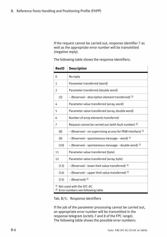
B. Reference Festo Handling and Positioning Profile (FHPP)
B−6 Festo P.BE−SFC−DC−CO−EN en 1005b
If the request cannot be carried out, response identifier 7 aswell as the appropriate error number will be transmitted(negative reply).
The following table shows the response identifiers:
ResID Description
0 No reply
1 Parameter transferred (word)
2 Parameter transferred (double word)
(3) � (Reserved � description element transferred) 1)
4 Parameter value transferred (array, word)
5 Parameter value transferred (array, double word)
6 Number of array elements transferred
7 Request cannot be carried out (with fault number) 2)
(8) � (Reserved � no supervising access for PKW interface) 1)
(9) � (Reserved � spontaneous message � word) 1)
(10) � (Reserved � spontaneous message � double word) 1)
11 Parameter value transferred (byte)
12 Parameter value transferred (array, byte)
(13) � (Reserved � lower limit value transferred) 1)
(14) � (Reserved � upper limit value transferred) 1)
(15) � (Reserved) 1)
1) Not used with the SFC−DC2) Error numbers see following table
Tab.�B/5: Response identifiers
If the job of the parameter processing cannot be carried out,an appropriate error number will be transmitted in theresponse telegram (octets 7 and 8 of the FPC range).The�following table shows the possible error numbers:

B. Reference Festo Handling and Positioning Profile (FHPP)
B−7Festo P.BE−SFC−DC−CO−EN en 1005b
Error numbers Description
0 0x00 Impermissible PNU. The parameter does not exist.
1 0x01 Parameter value cannot be modified (read only)
(2) 0x02 � (Reserved − lower or upper limit value exceeded) 1)
3 0x03 Faulty subindex
4 0x04 No array
5 0x05 Incorrect data type
(6) 0x06 � (Reserved � setting not permitted � can only be reset) 1)
(7) 0x07 � (Reserved � description element cannot be modified) 1)
(8) 0x08 � (Reserved � PPO−Write requested in IR does not exist) 1)
9 0x09 Description data do not exist
(10) 0x10 � (Reserved � access group incorrect) 1)
11 0x0A No supervising access
(12) 0x0B � (Reserved � password incorrect) 1)
13 0x0C Text not legible in cyclic exchange
(14) 0x0D � (Reserved � name not legible in cyclic exchange) 1)
(15) 0x0E � (Reserved � text array does not exist) 1)
(16) 0x10 � (Reserved � PPO−Write missing) 1)
(17) 0x11 � (Reserved � request cannot be processed because of operating status) 1)
(18) 0x12 � (Reserved � other errors) 1)
(19) 0x13 � (Reserved � date not legible in cyclic communication) 1)
(20) 0x14 � (Reserved � invalid value) 1)
(21) 0x15 � (Reserved � response too long) 1)
22 0x16 Impermissible: attributes, number of elements, PNU or IND
(23) 0x17 � (Reserved � Write request: impermissible format) 1)
24 0x18 Write request: number of values not permitted
(� 99) 0x64 � (Reserved � PROFIBUS)
100 0x65 � (Reserved � Festo: ReqID is not supported) 1)
(� 255) 0xFF � (Reserved � Festo)
1) These error numbers are not used

B. Reference Festo Handling and Positioning Profile (FHPP)
B−8 Festo P.BE−SFC−DC−CO−EN en 1005b
B.1.3 Rules for request−response processing
Rules Description
1 If the master sends the identifier for �No request", the SFC−DC replies with the responseidentifier for �No reply".
2 A request or response telegram always refers to a single parameter.
3 The master must continue to send a job until it receives the appropriate response fromthe SFC−DC.
4 The master recognises the response to the request placed:� by evaluating the response identifier� by evaluating the parameter number (PNU)� if applicable, by evaluating the subindex (IND)� if applicable, by evaluating the parameter value
5 The SFC−DC provides the response until the master sends a new request.
6 a) A write request, even with cyclic repetition of the same request, will only be carriedout once by the SFC−DC.
b) Between two consecutive requests with the same request identifier (ReqID),parameter number (PNU) and subindex (IND), the request identifier 0 (no request)must be sent and the response identifier 0 (no response) must be awaited.This�ensures that an �old" response is not interpreted as a �new" response.
Tab.�B/6: Rules for request−response processing

B. Reference Festo Handling and Positioning Profile (FHPP)
B−9Festo P.BE−SFC−DC−CO−EN en 1005b
Sequence of parameter processing
CautionObserve the following when modifying parameters:An FHPP control signal, which is to refer to a modifiedparameter, may only follow when the response identifier�Parameter value transferred" is received for the relevantparameter and if applicable for the index.
If, for example, a position value in a position register is to bemodified and if movement is then to be made to this position,the positioning command must not be given until the SFC−DChas completed and confirmed the modification of the positionregister.
CautionIn order to be sure that an �old" response cannot beinterpreted as a �new" response, the request identifier 0(no job) must be sent and the response identifier 0(no�response) must be awaited between two consecutiverequests with the same request identifier (ReqID),parameter number (PNU) and subindex (IND).
Evaluating errors
In the case of jobs which cannot be carried out, the slavereplies as follows:
� Output of response identifier = 7
� Output of an error number in bytes 5 and 6 of theparameter channel (FPC with CANopen).

B. Reference Festo Handling and Positioning Profile (FHPP)
B−10 Festo P.BE−SFC−DC−CO−EN en 1005b
B.1.4 Example of parametrisation
The following tables show an example of parametrisation of apositioning task in the position record table via FPC(Festo�Parameter Channel).
Step 1 Output status of the 8 bytes of FPC data:
Byte 1 Byte 2 Byte 3 Byte 4 Byte 5 Byte 6 Byte 7 Byte 8
Reserved Subindex ReqID/ResID + PNU Parameter value
O data 0x00 0x00 0x00 0x00 0x00 0x00 0x00 0x00
I data 0x00 0x00 0x00 0x00 0x00 0x00 0x00 0x00
Step 2 Write record number 1 with absolute positioning:PNU 401, subindex 2 � Modify parameter value, array,byte:�ReqID 12 (0xC) with value 0x00.
Byte 1 Byte 2 Byte 3 Byte 4 Byte 5 Byte 6 Byte 7 Byte 8
Reserved Subindex ReqID/ResID + PNU Parameter value
O data 0x00 0x02 0x91 0xC1 0x00 unused unused unused
I data 0x00 0x02 0x91 0xC1 0x00 0x00 0x00 0x00
Step 3 After receiving the input data with ResID 0xC, send O datawith ReqID = 0x0 and wait for input data with ResID�=�0x0:
Byte 1 Byte 2 Byte 3 Byte 4 Byte 5 Byte 6 Byte 7 Byte 8
Reserved Subindex ReqID/ResID + PNU Parameter value
O data 0x00 0x02 0x91 0x01 0x00 unused unused unused
I data 0x00 0x02 0x91 0x01 0x00 0x00 0x00 0x00

B. Reference Festo Handling and Positioning Profile (FHPP)
B−11Festo P.BE−SFC−DC−CO−EN en 1005b
Step 4 Write record number 1 with target position 0x1234(decimal�4660 increments):PNU 404, subindex 2 � Modify parameter value, array,double�word: ReqID 8 (0x8) with value 0x00001234.
Byte 1 Byte 2 Byte 3 Byte 4 Byte 5 Byte 6 Byte 7 Byte 8
Reserved Subindex ReqID/ResID + PNU Parameter value
O data 0x00 0x02 0x94 0x81 0x34 0x12 0x00 0x00
I data 0x00 0x02 0x94 0x81 0x34 0x12 0x00 0x00
Step 5 After receiving the input data with ResID 0x8 send O datawith ReqID = 0x0 and wait for input data with ResID�=�0x0:
Byte 1 Byte 2 Byte 3 Byte 4 Byte 5 Byte 6 Byte 7 Byte 8
Reserved Subindex ReqID/ResID + PNU Parameter value
O data 0x00 0x02 0x94 0x01 0x34 0x12 0x00 0x00
I data 0x00 0x02 0x94 0x01 0x34 0x12 0x00 0x00
Step 6 Write record number 1 with speed 0x7743(decimal�30531�increments/s):PNU 406, subindex 2 � Modify parameter value, array,double�word: ReqID 8 (0x8) with value 0x00007743.
Byte 1 Byte 2 Byte 3 Byte 4 Byte 5 Byte 6 Byte 7 Byte 8
Reserved Subindex ReqID/ResID + PNU Parameter value
O data 0x00 0x02 0x96 0x81 0x43 0x77 0x00 0x00
I data 0x00 0x02 0x96 0x81 0x43 0x77 0x00 0x00
Step 7 After receiving the input data with ResID 0x8 send O datawith ReqID = 0x0 and wait for input data with ResID�=�0x0:
Byte 1 Byte 2 Byte 3 Byte 4 Byte 5 Byte 6 Byte 7 Byte 8
Reserved Sub−index ReqID/ResID + PNU Parameter value
O data 0x00 0x02 0x01 0x94 0x43 0x77 0x00 0x00
I data 0x00 0x02 0x01 0x94 0x43 0x77 0x00 0x00

B. Reference Festo Handling and Positioning Profile (FHPP)
B−12 Festo P.BE−SFC−DC−CO−EN en 1005b
B.2 Reference parameters according to FHPP
B.2.1 Parameter groups
Group PNU 1) Description
Device data 100 � Device identification and device−specific settings, versionnumbers, passwords, etc.
Diagnostics 200 � Memory for diagnostic events: error numbers, fault time,incoming/outgoing event; management of the diagnosticmemory
Process data 300 � Current nominal and actual values, local I/Os, status data,operating panel queries etc.
Record list 400 � A record contains all the nominal value parameters requiredfor a positioning procedure
Project data� Force mode� Teach� Jog mode� Direct mode
500 � Basic project settings. Maximum speed and acceleration,offset project zero point etc. �> Parameters are the basis forthe record list.
Factor group 600 � Reserved
Axis data electric drives 1� Mechanics� Homing� Name plate� Standstill monitoring
1000 � All axis−specific parameters for electric drives.Gear�factor,�feed constant, reference parameter, etc.
1) Parameter number as per FHPP−FPC
Tab.�B/7: Parameter groups (FHPP)

B. Reference Festo Handling and Positioning Profile (FHPP)
B−13Festo P.BE−SFC−DC−CO−EN en 1005b
B.2.2 Object overview (Parameter number (PNU))
The following overview shows all defined parameters of theFHPP, with the parameter number PNU for parametrisation asper FHPP−FPC (I/O Messaging).
The parameters are described in appendix B.2.4 to B.2.19.
You will find an overview of the available CI objects inappendix C.4.1.
Name FHPP
PNU Subind.
B.2.4 Device data � standard parameters
Manufacturer Hardware Version (hardware version of the manufacturer) 100 �
Manufacturer Firmware Version (Firmware version of the manufacturer) 101 �
Version FHPP 102 �
Controller Serial Number 114 1 � 12
B.2.5 Device data � extended parameters
Manufacturer Device Name (Device name of the manufacturer) 120 1 � 25
User Device Name (Device name of the user) 121 1 � 25
Drive Manufacturer (manufacturer name) 122 1 � 30
HTTP Drive Catalog Address (HTTP address of manufacturer) 123 1 � 30
Festo Order Number 124 1 � 30
Device Control 125 �
HMI Parameter 126 1 � 4
Data Memory Control 127 1, 2
B.2.6 Diagnostics
Diagnostic Event 200 1 � 16
Error Number 201 1 � 16
Time Stamp 202 1 � 16
Diagnosis Memory Parameter 204 1 � 4
Device Errors 205 �
Fieldbus Diagnosis 206 1 � 6

B. Reference Festo Handling and Positioning Profile (FHPP)
B−14 Festo P.BE−SFC−DC−CO−EN en 1005b
Name FHPPName
Subind.PNU
B.2.7 Process data
Local Digital Inputs 303 �
Local Digital Outputs 304 1, 2
Cycle Number 305 �
B.2.8 Record list
Record Number 400 �
Record Control Byte 1 401 1 � 32
Record Target Position (target position positioning record) 404 1 � 32
Record Velocity (speed positioning record) 406 1 � 32
Record Acceleration (positioning record acceleration) 407 1 � 32
Record Deceleration (positioning record deceleration) 408 1 � 32
B.2.9 Project data � general project data
Project Zero Point (offset project zero point) 500 �
Software End Positions 501 1, 2
Max. Velocity (max. permitted speed) 502 �
Max. Acceleration (max. permitted acceleration) 503 �
B.2.10 Project data � force mode
Stroke Limit 510 �
Min. Torque/Force (min. permitted force/torque) 511 �
Max Torque/Force (Max. permitted force/torque) 512 �
B.2.11 Project data � teach
Teach Target 520 �
B.2.12 Project data � jog mode
Jog Mode Velocity Phase 2 (jog mode speed phase 2) 531 �
Jog Mode Acceleration 532 �
Jog Mode Deceleration 533 �
Jog Mode Time Phase 1 (jog mode time period phase 1) 534 �
B.2.13 Project data � direct positioning task
Direct Mode Acceleration 541 �
Direct Mode Deceleration 542 �

B. Reference Festo Handling and Positioning Profile (FHPP)
B−15Festo P.BE−SFC−DC−CO−EN en 1005b
Name FHPPName
Subind.PNU
B.2.14 Project data � direct task (force mode)
Force Target Window (message window for force reached) 552 �
Force Target Window Time (damping time for force reached) 553 �
Force Mode Speed Limit (speed limiting) 554 �
B.2.15 Axis data electric drives 1 � mechanical
Polarity (reversal of direction) 1000 �
Encoder Resolution 1001 1, 2
Gear Ratio 1002 1, 2
Feed Constant 1003 1, 2
Position Factor 1004 1, 2
Axis Parameter 1005 1 � 5
B.2.16 Axis data electric drives 1 � homing
Offset Axis Zero Point 1010 �
Homing Method (reference travel method) 1011 �
Homing Velocities (reference travel speeds) 1012 1, 2
Homing Required (reference travel required) 1014 �
Homing Max Torque (reference travel max. torque) 1015 �
B.2.17 Axis data electric drives 1 � control parameters
Halt Option Code 1020 �
Fault Reaction Option Code (error reaction option code) 1021 �
Target Position Window (position message window) 1022 �
Position Window Time (damping time for target reached) 1023 �
Position Control Parameter Set 1024 18 � 23, 32
Motor Data 1025 1, 3
Drive Data 1026 1 � 8
B.2.18 Axis data electric drives 1 � electronic type plate
Motor Type 1030 �
Maximum Current 1034 �
Motor Rated Current (nominal motor current) 1035 �
Motor Rated Torque (nominal motor torque) 1036 �

B. Reference Festo Handling and Positioning Profile (FHPP)
B−16 Festo P.BE−SFC−DC−CO−EN en 1005b
Name FHPPName
Subind.PNU
B.2.19 Axis data electric drives 1 � standstill monitoring
Position Target Value (setpoint position) 1040 �
Position Actual Value (current position) 1041 �
Standstill Position Window (standstill message window) 1042 �
Standstill Window Time (standstill delay time) 1043 �
Tab.�B/8: Overview of FHPP parameters

B. Reference Festo Handling and Positioning Profile (FHPP)
B−17Festo P.BE−SFC−DC−CO−EN en 1005b
B.2.3 Representation of the parameter entries
Encoder Resolution
FHPP 1001 1 � 2 Array uint32 rw
Description Encoder resolution in increments / revolutionsThe encoder resolution is fixed and cannot be modified by the user.The�calculated value is derived from the fraction(en�oder�increments/motor revolution).
Encoder Increments 1001 1 uint32 rw
Range of values: 0 ... 232 − 1Default: 500
Motor Revolutions 1001 2 uint32 rw
Fixed = 1
CI 608Fh 01h � 02h Array uint32 rw
CANopen 608Fh 01h � 02h Array uint32 rw
1 Name of the parameter in English
2 PNU (parameter number)
3 Subindices of the parameter, if present (�: no subindex, simple variable)
4 Element class
5 Element variable type.
6 Read/write permission: ro = read only, wo = write only
7 Description of the parameter
8 Name and description of subindices, if present (entry relating to FHPP, if available)
9 Corresponding and CANopen or CI object, if present
Bild�B/1: Representation of the parameter entries
1 2 3 4 5 6
7
8
9

B. Reference Festo Handling and Positioning Profile (FHPP)
B−18 Festo P.BE−SFC−DC−CO−EN en 1005b
B.2.4 Device data � Standard parameters
Manufacturer Hardware Version
FHPP 100 � Var uint16 ro
Description Coding of the hardware version, specification in BCD: xxyy(xx = main version, yy = secondary version)
CI 2069h 00h Var uint16 ro
CANopen 2069h � Var uint16 rop
see Object 1009h
Manufacturer Firmware Version
FHPP 101 � Var uint16 ro
Description Firmware version, specified in BCD (binary coded decimal): xxyy(xx = main version, yy = secondary version)
CI 206Ah 00h Var uint16 ro
CANopen 206Ah � Var uint16 rop
Compare Object 100Ah
Version FHPP
FHPP 102 � Var uint16 ro
Description Version number of FHPP, specified in BCD (binary coded decimal): xxyy(xx = main version, yy = secondary version)
CI 2066h 00h Var uint16 ro
CANopen 2066h � Var uint16 ro
Controller Serial Number
FHPP 114 1 � 12 Array char ro
Description 12−digit code for identifying the controller. e.g. �081007PN0636"
CI 2072h 00h Var V−string ro
CANopen 2072h � Var V−string ro

B. Reference Festo Handling and Positioning Profile (FHPP)
B−19Festo P.BE−SFC−DC−CO−EN en 1005b
B.2.5 Device data � Extended parameters
Manufacturer Device Name
FHPP 120 1 � 25 Array char ro
Description Drive designation, e.g.: �SFC−DC−VC−3−E−H2−CO"
CI 1008h 00h Var V−string ro
CANopen 1008h � Var V−string ro
User Device Name
FHPP 121 1 � 25 Array char ro
Description Designation of the drive by the user, max. 24 characters (ASCII, 7−bit).Default: �motor001"
CI 20FDh 00h Var V−string rw
CANopen 20FDh � Var V−string rw
Drive manufacturer
FHPP 122 1 � 30 Array char ro
Description Name of drive manufacturer: �Festo AG & Co. KG"
CI 6504h 00h Var V−string ro
CANopen / CI 6504h � Var V−string ro
HTTP Drive Catalog Address
FHPP 123 1 � 30 Array char ro
Description Internet address of the manufacturer: �www.festo.com"
CI 6505h 00h Var V−string ro
CANopen 6505h � Var V−string ro

B. Reference Festo Handling and Positioning Profile (FHPP)
B−20 Festo P.BE−SFC−DC−CO−EN en 1005b
Festo Order Number
FHPP 124 1 � 30 Array char ro
Description Festo order number, e.g.��540364" or �540365"
CI 6503h 00h Var V−string ro
CANopen 6503h � Var V−string rop
�Drive Catalog Number"
Device Control
FHPP 125 � Var uint8 rw
Description Activates/deactivates control via the SFC−DC interfaces.Corresponds to �HMI control" on the control panel and �FCT/HMI" on the FCT.0 (0x00): Control via control interface deactivated (fieldbus),
via HMI (control panel) and FCT activated1 (0x01): Control via controller interface activated (default)
CI 207Dh 00h Var uint8 rw
CANopen 207Dh � Var uint8 rw
HMI parameters
FHPP 126 1 � 4 Array uint8 ro
Description Parametrisation of the HMI functions (only with SFC−DC−...−H2−...)
LCD Current 126 1 uint8 CI: rw
Range of values: 1 � 5 (0x01 � 0x05). Default: 5
LCD Contrast 126 2 uint8 CI: rw
Range of values: 0 � 63 (0x00 � 0x3F). Default: 10
Measure 126 3 uint8 CI: rw
Defining the measuring system for the LCD display. See object 20D0h.Fixed: 1 (0x01): Metric measuring units � mm, mm/s, mm/s2
Scaling Factor 126 4 uint8 CI: rwg Number of post−decimal positionsFixed: 2 (0x02): 2 post−decimal positions
CI 20FFh 01h � 04h Array uint8 rw
CANopen 20FFh 01h � 04h Array uint8 rw

B. Reference Festo Handling and Positioning Profile (FHPP)
B−21Festo P.BE−SFC−DC−CO−EN en 1005b
Data Memory Control
FHPP 127 1, 2 Array uint8 rw 1)
Description Commands for the EEPROM (non−volatile data storage).
Delete EEPROM 127 1 uint8 rw
When the object is written and after Power Off/On the data in EEPROM isdeleted. Please note also the following instructions.Fixed: 16 (0x10): Restore factory settings (delete data in EEPROM)
Save Data 127 2 uint8 rw The data in EEPROM will be overwritten with the current user−specific settings.Fix 1 (0x01): Save data
CI 20F1h 01h, 02h Array uint8 rw 1)
CANopen 20F1h 01h, 02h Array uint8 rw 1)
1) When reading the reply ’0’ always occurs
NoteAll user−specific settings will be lost on deletion(except�for�cycle number). The status after deletioncorresponds to the standard factory setting.
The gear factor is set to the standard factory setting forthe�SLTE.
· To set the gear factor: Consult Festo Service.
· Always carry out a first commissioning after deleting theEEPROM.
· When the EEPROM is deleted, the fieldbus parametersare also reset.

B. Reference Festo Handling and Positioning Profile (FHPP)
B−22 Festo P.BE−SFC−DC−CO−EN en 1005b
B.2.6 Diagnostics
Description of the method of operation of the diagnosticmemory, see chapter 6.4.
Diagnostic Event
FHPP 200 1 � 16 Array uint8 ro
Description Type of fault or diagnostic information saved in the diagnostic memory. Displays whether an incoming or outgoing fault is saved.Value Type of diagnostic event
0 (0x00) No fault (or fault message deleted)1 (0x01) Incoming fault2 (0x02) Outgoing fault3 (0x03) Reserved4 (0x04) Overrun time stamp
Event 1 200 1 uint8 ro Active diagnostic event
Event 2 200 2 uint8 ro Previous diagnostic event
Event � 200 � uint8 ro �
Event 16 200 16 uint8 ro Oldest saved diagnostic event
CI 20C8h 01h � 10h Array uint8 ro
CANopen 20C8h 01h � 10h Array uint8 ro
Error Number
FHPP 201 1 � 16 Array uint16 ro
Description Error number saved in the diagnostic memory, serves to identify themalfunction. See chapter 6.3 for error numbers.
Event � 201 � uint16 ro See PNU 200
CI 20C9h 01h � 10h Array uint16 ro
CANopen 20C9h 01h � 10h Array uint16 ro

B. Reference Festo Handling and Positioning Profile (FHPP)
B−23Festo P.BE−SFC−DC−CO−EN en 1005b
Time Stamp
FHPP 202 1 � 16 Array uint32 ro
Description Time of the diagnostic event in the unit after PNU 204/2 since being switchedon. In the event of an overrun the time stamp jumps from 0xFFFFFFFF to 0, anentry: �Overrun time stamp" is created in the diagnostic memory.
Event � 202 � uint32 ro See PNU 200
CI 20CAh 01h � 10h Array uint32 ro
CANopen 20CAh 01h � 10h Array uint32 ro
Diagnosis Memory Parameter
FHPP 204 1 � 4 Array uint8 rw/ro
Description Configuration of the diagnostic memory
Fault Type 204 1 uint8 rwyp Incoming and outgoing malfunctions.1 (0x01): Log incoming and outgoing*) malfunctions (default)2 (0x02) Log only incoming malfunctions*) Outgoing malfunction = time when the fault was acknowledged.
Resolution 204 2 uint8 rw 1 (0x01): Resolution time stamp 10 ms (default)2 (0x02): Resolution time stamp 1 ms
Clear Memory 204 3 uint8 rwy Clear diagnostic memory by writing value = 1Read is always answered with value = 0.
Number of Entries 204 4 uint8 ro Number of entries in the diagnostic memory.Range of values: 0 � 15 (0x00 � 0x0F)
CI 20CCh 01h � 04h Array uint8 rw/ro
CANopen 20CCh 01h � 04h Array uint8 rw/ro
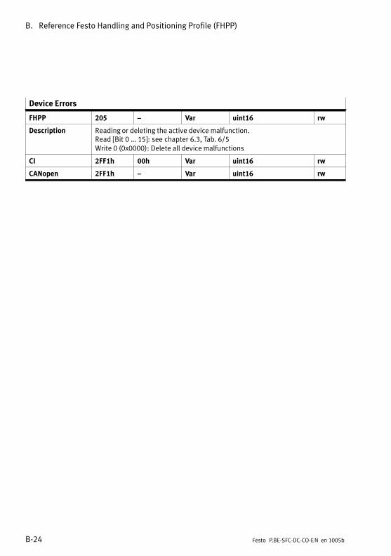
B. Reference Festo Handling and Positioning Profile (FHPP)
B−24 Festo P.BE−SFC−DC−CO−EN en 1005b
Device Errors
FHPP 205 � Var uint16 rw
Description Reading or deleting the active device malfunction.Read [Bit 0 � 15]: see chapter 6.3, Tab.�6/5Write 0 (0x0000): Delete all device malfunctions
CI 2FF1h 00h Var uint16 rw
CANopen 2FF1h � Var uint16 rw
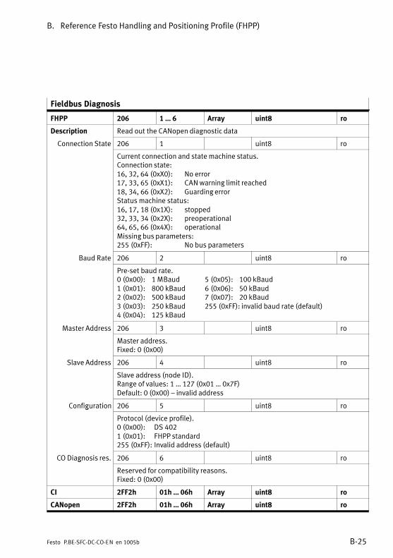
B. Reference Festo Handling and Positioning Profile (FHPP)
B−25Festo P.BE−SFC−DC−CO−EN en 1005b
Fieldbus Diagnosis
FHPP 206 1 � 6 Array uint8 ro
Description Read out the CANopen diagnostic data
Connection State 206 1 uint8 ro Current connection and state machine status.Connection state:16, 32, 64 (0xX0): No error17, 33, 65 (0xX1): CAN warning limit reached18, 34, 66 (0xX2): Guarding errorStatus machine status:16, 17, 18 (0x1X): stopped32, 33, 34 (0x2X): preoperational64, 65, 66 (0x4X): operationalMissing bus parameters:255 (0xFF): No bus parameters
Baud Rate 206 2 uint8 ro Pre−set baud rate.0 (0x00): 1 MBaud 5 (0x05): 100 kBaud1 (0x01): 800 kBaud 6 (0x06): 50 kBaud2 (0x02): 500 kBaud 7 (0x07): 20 kBaud3 (0x03): 250 kBaud 255 (0xFF): invalid baud rate (default)4 (0x04): 125 kBaud
Master Address 206 3 uint8 ro Master address.Fixed: 0 (0x00)
Slave Address 206 4 uint8 ro Slave address (node ID).Range of values: 1 � 127 (0x01 � 0x7F)Default: 0 (0x00) � invalid address
Configuration 206 5 uint8 rog Protocol (device profile).0 (0x00): DS 4021 (0x01): FHPP standard255 (0xFF): Invalid address (default)
CO Diagnosis res. 206 6 uint8 rog
Reserved for compatibility reasons.Fixed: 0 (0x00)
CI 2FF2h 01h � 06h Array uint8 ro
CANopen 2FF2h 01h � 06h Array uint8 ro

B. Reference Festo Handling and Positioning Profile (FHPP)
B−26 Festo P.BE−SFC−DC−CO−EN en 1005b
B.2.7 Process data
Local Digital Inputs
FHPP 303 � Var uint32 ro
Description Map of the digital inputs. Provides the status of special inputs.Bit 0, 1: Reserved (= 0)Bit 2: Reference switch (1 = reference input supplies 0−signal)Bit 3 � 15: Reserved (= 0)Bit 16 � 20: Current record number (compare to control byte 3)Bit 21: STOP (CCON.B1) or internal status �Stop"Bit 22: ENABLE (CCON.B0) or internal status �Drive enabled"Bit 23: START (CPOS.B1) or internal status �Job started"Bit 24 � 31: Reserved (= 0)
CI 60FDh 00h Var uint32 ro
CANopen 60FDh � Var uint32 ro
Local Digital Outputs
FHPP 304 1, 2 Array uint32 rw
Description Map of the digital outputs.
Digital Outputs 304 1 uint32 rwg p Status of special outputs (written values are not adopted).Bit 0 � 15: Reserved (= 0)Bit 16: MC (SPOS.B2) or internal status �Motion Complete"Bit 17: ENABLED (SCON.B0) or internal status �Ready for operation"Bit 18: ACK (SPOS.B1) or internal status �Start signal accepted"Bit 19: FAULT (SCON.B3) or internal status �Fault"Bit 20 � 31: Reserved (= 0)
Mask 304 2 uint32 rw Fixed = 0 (written values are not adopted).
CI 60FEh 01h, 02h Array uint32 rw
CANopen 60FEh 01h, 02h Array uint32 rw

B. Reference Festo Handling and Positioning Profile (FHPP)
B−27Festo P.BE−SFC−DC−CO−EN en 1005b
Cycle Number
FHPP 305 � Var uint32 ro
Description Number of positioning records executed, homing runs etc.Range of values: 0 � +(232 − 1)
CI 2FFFh 00h Var uint32 ro
CANopen 2FFFh � Var uint32 ro

B. Reference Festo Handling and Positioning Profile (FHPP)
B−28 Festo P.BE−SFC−DC−CO−EN en 1005b
B.2.8 Record list
Record no. RCB1 Setpointposition
Speed Acc.Move�ment to
Acc.Brake
FHPP PNU 400 401 404 406 407 408
Type uint8 uint8 int32 uint32 uint32 uint32
Data Record no. 0 Homing
Record no. 1 Record controlbyte forrecord�1
Setpointvalue forrecord 1
Setpointvalue forrecord 1
Setpointvalue forrecord 1
Setpointvalue forrecord 1
� � Setpointvalue forrecord 2
Setpointvalue forrecord 2
Setpointvalue forrecord 2
Setpointvalue forrecord 2
� � � � � �
Record no. 31 Record controlbyte forrecord�31
Setpointvalue forrecord 31
Setpointvalue forrecord 31
Setpointvalue forrecord 31
Setpointvalue forrecord 31
32 Reserved (data for Jog mode)
33 Reserved (data for Direct mode)
Tab.�B/9: Structure of FHPP record list
FHPP In FHPP, record selection for reading and writing is made viathe subindex of the PNUs 401 � 408. The record to be executed is selected via the record numberin PDO1. PNU 400 is needed only for teaching records indirect operation.
For DS 402 the record selection is made with object 2032h.The selected record is then addressed with object 20E0h,with the record element being selected with the subindex;see chapter C.1.3, table Tab.�C/2.
Record Number
FHPP 400 � Var uint8 rw
Description The active / selected record. It is also valid when the drive is not in RecordSelect mode (e.�g. during teaching). In Record selection mode this parameter istransferred in the cyclic I/O data.Range of values: 0 � 31 (0x00 � 0x1F)
CI 2033h � Var uint8 rw
CANopen Note: Object 2032h is intended for access via CANopen!

B. Reference Festo Handling and Positioning Profile (FHPP)
B−29Festo P.BE−SFC−DC−CO−EN en 1005b
Record Control Byte 1
FHPP 401 1 � 32 Array uint8 rw
Description Record control byte 1 (RCB1) controls important settings for the positioning jobin Record selection mode. The record control byte is bit−orientated:Bit 0: Setpoint value absolute/relativeBit 1 � 7: Reserved (= 0)Values:0 (0x00): Nominal value is absolute (default)1 (0x01): Setpoint value is relative to the last setpoint value/
switch�further�value
Record 0 401 1 uint8 rw
Do not use (homing)
Record � 401 � uint8 rw
Record control byte for positioning records 1 � 30
Record 31 401 32 uint8 rw3
Record control byte for positioning record 31
CI 20EAh 01h � 20h Array uint8 rw
CANopen Note: Object 20E0h/01h is intended for access via CANopen!
Record Target Position
FHPP 404 1 � 32 Array int32 rw
Description Target positions of the positioning record table.Absolute or relative in increments as per PNU 401 / RCB1.Range of values: −231 � +(231 − 1)Default: 0
Record 0 404 1 int32 rw
Do not use (homing)
Record � 404 � int32 rw
Target position of positioning records 1 � 30
Record 31 404 32 int32 rw3
Target position of positioning record 31
CI 20ECh 01h � 20h Array int32 rw
CANopen Note: Object 20E0h/02h is intended for access via CANopen!

B. Reference Festo Handling and Positioning Profile (FHPP)
B−30 Festo P.BE−SFC−DC−CO−EN en 1005b
Record speed
FHPP 406 1 � 32 Array uint32 rw
Description Setpoint speed value in increments/sRange of values: 1)
Axis type Values
SLTE−10: 0 � 305309 (Z 0 � 170 mm/s)SLTE−16: 0 � 491076 (Z 0 � 210 mm/s)HGPLE−14/GEH60: 0 � 674019 (Z 0 � 55 mm/s)HGPLE−25/GEH61: 0 � 347593 (Z 0 � 65 mm/s)DEF: 0 � 216000 (Z 0 � 388.8 °/s)for user−defined axis length: 0 � max. speed (PNU 502)Default: dependent on the axis type
Record 0 406 1 uint32 rw
Do not use (homing)
Record � 406 � uint32 rw
Speed of positioning record 1 � 30
Record 31 406 32 uint32 rw3
Speed of positioning record 31
CI 20EDh 01h � 20h Array uint32 rw
Additional subindex of object 20EDh see PNU 531
CANopen Note: Object 20E0h/03h is intended for access via CANopen!
1) Range of values dependent on the axis type (PNU 1005/4) and axis length (PNU 1005/5)

B. Reference Festo Handling and Positioning Profile (FHPP)
B−31Festo P.BE−SFC−DC−CO−EN en 1005b
Record Acceleration
FHPP 407 1 � 32 Array uint32 rw
Description Setpoint acceleration value for moving in increments/s2
The acceleration can only be specified for Positioning mode.Range of values: 1)
Axis type Values
SLTE−10: 897969 � 4489845 (Z 500 � 2500 mm/s2)SLTE−16: 1169230 � 5846154 (Z 500 � 2500 mm/s2)HGPLE−14/GEH60: 1225490 � 12254901 (Z 100 � 1000 mm/s2)HGPLE−25/GEH61: 534759 � 5347593 (Z 100 � 1000 mm/s2)DEF: 200000 � 5000000 (Z 360 � 9,000 °/s2)for user−defined axis length: 0 � Max. acceleration (PNU 503)Default:SLTE: 500 mm/s2
HGPLE/GEH: 100 mm/s2
DEF: 360 °/s2
Value is automatically entered when an axis type is selected (PNU 1005/4).
Record 0 407 1 uint32 rw
Do not use (homing)
Record � 407 � uint32 rw
Acceleration for positioning records 1 � 30
Record 31 407 32 uint32 rw3
Acceleration for positioning record 31
CI 20EEh 01h � 20h Array uint32 rw
Additional subindices of object 20EEh see PNU 532 and 541
CANopen Note: Object 20E0h/04h is intended for access via CANopen!
1) Range of values dependent on the axis type (PNU 1005/4) and axis length (PNU 1005/5)

B. Reference Festo Handling and Positioning Profile (FHPP)
B−32 Festo P.BE−SFC−DC−CO−EN en 1005b
Record Deceleration
FHPP 408 1 � 32 Array uint32 rw
Description Setpoint for braking (deceleration) in increments/s2
The deceleration can only be specified for Positioning mode.Value is automatically entered when an axis type is selected (PNU 1005/4).Value range and default: See PNU 407
Record 0 408 1 uint32 rw
Do not use (homing)
Record � 408 � uint32 rw
Deceleration for positioning records 1 � 30
Record 31 408 32 uint32 rw3
Deceleration for positioning record 31
CI 20EFh 01h � 20h Array uint32 rw
Additional subindices of object 20EFh see PNU 533 and 542
CANopen Note: Object 20E0h/05h is intended for access via CANopen!
1) Depends on axis type, see PNU 1005/04
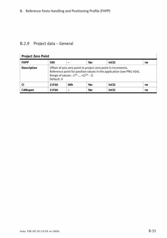
B. Reference Festo Handling and Positioning Profile (FHPP)
B−33Festo P.BE−SFC−DC−CO−EN en 1005b
B.2.9 Project data � General
Project Zero Point
FHPP 500 � Var int32 rw
Description Offset of axis zero point to project zero point in increments.Reference point for position values in the application (see PNU 404).Range of values: −231 � +(231 − 1)Default: 0
CI 21F4h 00h Var int32 rw
CANopen 21F4h � Var int32 rw
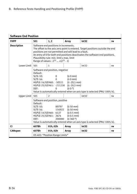
B. Reference Festo Handling and Positioning Profile (FHPP)
B−34 Festo P.BE−SFC−DC−CO−EN en 1005b
Software End Position
FHPP 501 1, 2 Array int32 rw
Description Software end positions in increments.The offset to the axis zero point is entered. Target positions outside the endpositions are not permitted and will lead to a fault.An entry of 0 for both end positions deactivates the software end positions.Plausibility rule: min. limit � max. limitRange of values: −231 � +(231 − 1)
Lower Limit 501 1 int32 rw
Software end position, negativeDefault:SLTE−10: 0 (Z 0 mm)SLTE−16: 0 (Z 0 mm)HGPLE−14/GEH60: −50511 (Z −29,5 mm)HGPLE−25/GEH61: −211230 (Z −39,5 mm)DEF: 0 (Z 0 °)Value is automatically entered when an axis type is selected (PNU 1005/4).
Upper Limit 501 2 int32 rwpp
Software end position, positiveDefault:SLTE−10: 89797 (Z 50 mm)SLTE−16: 116922 (Z 50 mm)HGPLE−14/GEH60: 6127 (Z 0.5 mm)HGPLE−25/GEH61: 2674 (Z 0.5 mm)DEF: 200000 (Z 360 °)Value is automatically entered when an axis type is selected (PNU 1005/4).
CI 607Bh 01h, 02h Array int32 rw
CANopen 607Bh 01h, 02h Array int32 rwp
DS 402: �Position Range Limits"

B. Reference Festo Handling and Positioning Profile (FHPP)
B−35Festo P.BE−SFC−DC−CO−EN en 1005b
Max. speed
FHPP 502 � Var uint32 rw
Description Maximum permissible speed in increments/s. The specifications in Direct modeand in the record table refer to this value.Dependent on the axis type (PNU 1005/4) and axis length (PNU 1005/5):� The values are permanently set by selection of the axis type or automatically
entered. Other values are not allowed.� For user−defined axis lengths, the values can be freely written.SLTE−10: 305309 (Z 170 mm/s)SLTE−16: 491076 (Z 210 mm/s)HGPLE−14/GEH60: 674019 (Z 55 mm/s)HGPLE−25/GEH61: 347593 (Z 65 mm/s)DEF: 216000 (Z 388.8 °/s)Value is automatically entered when an axis type is selected (PNU 1005/4).
CI 21F6h 00h Var uint32 rw
CANopen 21F6h � Var uint32 rw
Max. Acceleration
FHPP 503 � Var uint32 rw
Description Max. permitted acceleration in increments/s2. The specifications in Direct modeand in the record table refer to this value.Dependent on the axis type (PNU 1005/4) and axis length (PNU 1005/5):� The values are permanently set by selection of the axis type or automatically
entered. Other values are not allowed.� For user−defined axis lengths, the values can be freely written.SLTE−10: 4489845 (Z 2500 mm/s2)SLTE−16: 5846154 (Z 2500 mm/s2)HGPLE−14/GEH60: 12254901 (Z 1000 mm/s2)HGPLE−25/GEH61: 5347593 (Z 1000 mm/s2)DEF: 5000000 (Z 9000 °/s2)Value is automatically entered when an axis type is selected (PNU 1005/4).
CI 21F7h 00h Var uint32 rw
CANopen 21F7h � Var uint32 rw

B. Reference Festo Handling and Positioning Profile (FHPP)
B−36 Festo P.BE−SFC−DC−CO−EN en 1005b
B.2.10 Project data � Force mode
Stroke Limit
FHPP 510 � Var uint32 rw
Description Maximum permitted stroke with active Force mode.With active force control, the actual position relative to the start position mustnot change by more than the amount specified in this parameter. In this wayyou can ensure that the axis will not perform an uncontrolled movement ifForce�mode is activated by mistake (e.g. missing workpiece). This parameter istaken into account in all control modes in which the position controller is notactive in the status �Operation enabled".Monitoring can be deactivated when bit RCB1.B5 is set.Range of values: 0 � +(232 − 1)Default:SLTE−10: 17959 (Z 10 mm)SLTE−16: 23384 (Z 10 mm)HGPLE−14/GEH60: 112246 (Z 10 mm)HGPLE−25/GEH61: 53475 (Z 10 mm)DEF: 20000 (Z 36°)Value is automatically entered when an axis type is selected (PNU 1005/4).
CI 60F6h 01h uint32 rw
CANopen 60F6h 01h uint32 rw
Min. Torque/Force
FHPP 511 � Var uint16 rw
Description The lowest permissible torque (force) of the motor.Specified in 1/1000 of the rated torque (PNU 1036 / Object 6076h)Range of values: 0 � 1000 (0x03E8)Default: 0
CI 60F6h 05h uint16 rw
CANopen 60F6h 05h uint16 rw

B. Reference Festo Handling and Positioning Profile (FHPP)
B−37Festo P.BE−SFC−DC−CO−EN en 1005b
Max Torque/Force
FHPP 512 � Var uint16 rw
Description The highest permissible torque (force) of the motor.Specified in 1/1000 of the rated torque (PNU 1036 / 6076h)Range of values: 0 � 1000 (0x03E8)Default: 1000
CI 6072h 00h Var uint16 rw
CANopen 6072h � Var uint16 rw
B.2.11 Project data � Teaching
Teach Target
FHPP 520 � Var uint8 rw
Description The parameter defined is the one written with the actual position by the nextTeach command (see chapter 5.6.3).Values:1 (0x01): Setpoint position in positioning record (default).
� With Record selection: positioning record as per FHPP control�bytes� with Direct mode: Positioning record as per PNU 400
2 (0x02): Axis zero point3 (0x03): Project zero point4 (0x04): Lower software end position5 (0x05): Upper software end position
CI 21FCh 00h Var uint8 rw
CANopen 21FCh � Var uint8 rw

B. Reference Festo Handling and Positioning Profile (FHPP)
B−38 Festo P.BE−SFC−DC−CO−EN en 1005b
B.2.12 Project data � Jog mode
Jog Mode Velocity Phase 2
FHPP 531 � Var uint32 rw
Description Maximum speed for phase 2 in increments/s.Range of values: 1)
Axis type Values
SLTE−10: 0 � 305309 (Z 0 � 170 mm/s)SLTE−16: 0 � 491076 (Z 0 � 210 mm/s)HGPLE−14/GEH60: 0 � 674019 (Z 0 � 55 mm/s)HGPLE−25/GEH61: 0 � 347593 (Z 0 � 65 mm/s)DEF: 0 � 216000 (Z 0 � 388.8 °/s)for user−defined axis length: 0 � max. speed (PNU 502)Default:SLTE−10: 30530 (Z 17 mm/s) SLTE−16: 49107 (Z 21 mm/s) HGPLE−14/GEH60: 89460 (Z 7.3 mm/s) HGPLE−25/GEH61: 39037 (Z 7.3 mm/s)DEF: 21666 (Z 39 °/s)Value is automatically entered when an axis type is selected (PNU 1005/4).
CI 20EDh 21h Array uint32 rw
CANopen 20EDh 21h Array uint32 rw
For additional subindices of object 20EDh see PNU 406
1) Range of values dependent on the axis type (PNU 1005/4) and axis length (PNU 1005/5)

B. Reference Festo Handling and Positioning Profile (FHPP)
B−39Festo P.BE−SFC−DC−CO−EN en 1005b
Jog Mode Acceleration
FHPP 532 � Var uint32 rw
Description Acceleration in increments/s2.Range of values: 1)
Axis type Values
SLTE−10: 897969 � 4489845 (Z 500 � 2500 mm/s2)SLTE−16: 1169230 � 5846154 (Z 500 � 2500 mm/s2)HGPLE−14/GEH60: 1225490 � 12254901 (Z 100 � 1000 mm/s2)HGPLE−25/GEH61: 534759 � 5347593 (Z 100 � 1000 mm/s2)DEF: 200000 � 5000000 (Z 360 � 9,000 °/s2)for user−defined axis length: 0 � Max. acceleration (PNU 503)Default:SLTE: 500 mm/s2
HGPLE/GEH: 100 mm/s2
DEF: 360 °/s2
Value is automatically entered when an axis type is selected (PNU 1005/4).
CI 20EEh 21h Array uint32 rw
CANopen 20EEh 21h Array uint32 rw
Additional subindices of object 20EEh see PNU 407 and 541
1) Range of values dependent on the axis type (PNU 1005/4) and axis length (PNU 1005/5)
Jog Mode Deceleration
FHPP 533 � Var uint32 rw
Description Deceleration in increments/s2.Value range and default: See PNU 532
CI 20EFh 21h Array uint32 rw
CANopen 20EFh 21h Array uint32 rw
Additional subindices of object 20EFh see PNU 408 and 542

B. Reference Festo Handling and Positioning Profile (FHPP)
B−40 Festo P.BE−SFC−DC−CO−EN en 1005b
Jog Mode Time Phase 1
FHPP 534 � Var uint32 rw
Description Time period of phase 1 (T1) in msRange of values: 0 � +(232 − 1)Default: 2000 (0x000007D0)
CI 20E9h 21h Array uint32 rw
CANopen 20E9h � 1) Array uint32 rwp
1) Subindex dependent on data profile (Object 2FF2h/05h / PNU 206):� DS 402: 20E9/00h � Var� FHPP: 20E9/21h � Array

B. Reference Festo Handling and Positioning Profile (FHPP)
B−41Festo P.BE−SFC−DC−CO−EN en 1005b
B.2.13 Project data � Direct mode (Positioning mode)
Direct Mode Acceleration
FHPP 541 � Var uint32 rw
Description Acceleration in direct mode in increments/s2.Range of values: 1)
Axis type Values
SLTE−10: 897969 � 4489845 (Z 500 � 2500 mm/s2)SLTE−16: 1169230 � 5846154 (Z 500 � 2500 mm/s2)HGPLE−14/GEH60: 1225490 � 12254901 (Z 100 � 1000 mm/s2)HGPLE−25/GEH61: 534759 � 5347593 (Z 100 � 1000 mm/s2)DEF: 200000 � 5000000 (Z 360 � 9,000 °/s2)for user−defined axis length: 0 � Max. acceleration (PNU 503)Default:SLTE: 500 mm/s2
HGPLE/GEH: 100 mm/s2
DEF: 360 °/s2
Value is automatically entered when an axis type is selected (PNU 1005/4).
CI 20EEh 22h Array uint32 rw
Additional subindices of object 20EEh see PNU 407 and 532
CANopen Access via CANopen, see PDO 2, 6083h
1) Range of values dependent on the axis type (PNU 1005/4) and axis length (PNU 1005/5)
Direct Mode Deceleration
FHPP 542 � Var uint32 rw
Description Deceleration in direct mode in increments/s2.Value range and default: See PNU 541
CI 20EFh 22h Array 1) uint32 rw
Additional subindices of object 20EFh see PNU 408 and 533
CANopen Access via CANopen, see PDO 2, 6084h
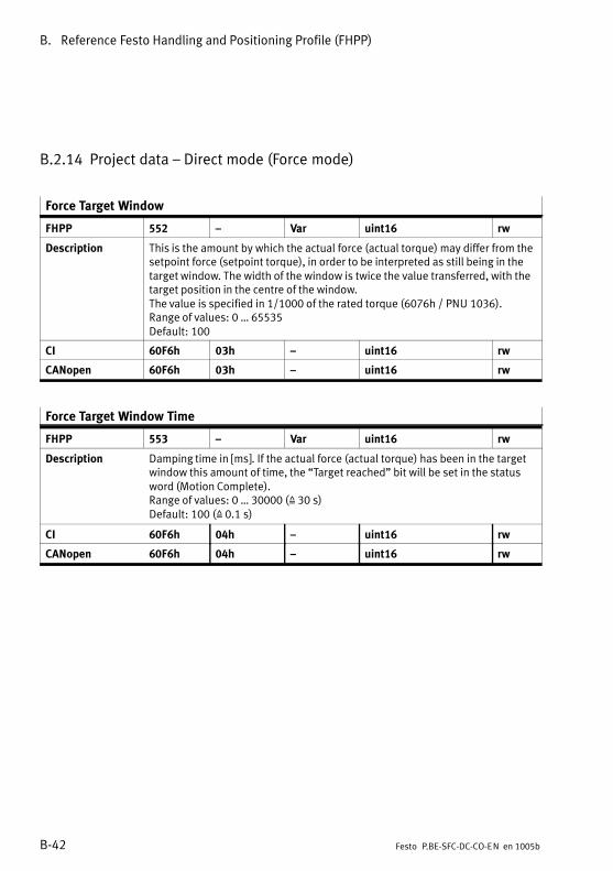
B. Reference Festo Handling and Positioning Profile (FHPP)
B−42 Festo P.BE−SFC−DC−CO−EN en 1005b
B.2.14 Project data � Direct mode (Force mode)
Force Target Window
FHPP 552 � Var uint16 rw
Description This is the amount by which the actual force (actual torque) may differ from thesetpoint force (setpoint torque), in order to be interpreted as still being in thetarget window. The width of the window is twice the value transferred, with thetarget position in the centre of the window.The value is specified in 1/1000 of the rated torque (6076h / PNU 1036).Range of values: 0 � 65535Default: 100
CI 60F6h 03h � uint16 rw
CANopen 60F6h 03h � uint16 rw
Force Target Window Time
FHPP 553 � Var uint16 rw
Description Damping time in [ms]. If the actual force (actual torque) has been in the targetwindow this amount of time, the �Target reached" bit will be set in the statusword (Motion Complete).Range of values: 0 � 30000 (Z 30 s)Default: 100 (Z 0.1 s)
CI 60F6h 04h � uint16 rw
CANopen 60F6h 04h � uint16 rw

B. Reference Festo Handling and Positioning Profile (FHPP)
B−43Festo P.BE−SFC−DC−CO−EN en 1005b
Force Mode Speed Limit
FHPP 554 � Var uint32 rw
Maximum permitted speed with active Force mode, in increments/s.In this way you can ensure that the axis will not undergo uncontrolledacceleration and move at high speed against a stop if force control is activatedby mistake (e.g.�workpiece missing). This parameter is taken into account in allcontrol modes in which the position controller is not active in the status�Operation enabled".Range of values: 1)
Axis type Values
SLTE−10: 0 � 305309 (Z 0 � 170 mm/s)SLTE−16: 0 � 491076 (Z 0 � 210 mm/s)HGPLE−14/GEH60: 2 � 428921 (Z 0 � 35 mm/s)HGPLE−25/GEH61: 2 � 267379 (Z 0 � 50 mm/s)DEF: 0 � Max. permitted speed (PNU 502, object 21F6h)
for user−defined axis length: 0 � max. speed (PNU 502)Default:SLTE−10: 17959 (Z 10 mm/s)SLTE−16: 23384 (Z 10 mm/s)HGPLE−14/GEH60: 122549 (Z 10 mm/s)HGPLE−25/GEH61: 53475 (Z 10 mm/s)DEF: 20000 (Z 36°/s)Value is automatically entered when an axis type is selected (PNU 1005/4).
CI 60F6h 02h � uint32 rw
CANopen 60F6h 02h � uint32 rw
1) Range of values dependent on the axis type (PNU 1005/4) and axis length (PNU 1005/5)..
The force control is not approved for the mini slides and rotary modules; this can only be activatedfor user−defined axes via object 6502.

B. Reference Festo Handling and Positioning Profile (FHPP)
B−44 Festo P.BE−SFC−DC−CO−EN en 1005b
B.2.15 Axis parameter electric drive 1 � Mechanical
Polarity
FHPP 1000 � Var uint8 rw
Description With this parameter the �+/−" direction of the position values (vectors) can beassigned to the direction of rotation of the motor shaft (see chapter 1.6).A�new�homing is then required.Values:0 (0x00) = Factory setting
(�+" corresponds to rotational movement in a clockwise direction)128 (0x80) = Reverse direction
(�+" corresponds to rotational movement in an anti−clockwisedirection)
CI 607Eh 00h Var uint8 rw
CANopen 607Eh � Var uint8 rw
Encoder Resolution
FHPP 1001 1, 2 Array uint32 rw
Description Encoder resolution calculated from [encoder increments / motor revolutions]
Encoder Increments 1001 1 uint32 rw Values (fixed, read−only):SLTE−10: 512SLTE−16: 1000HGPLE/GEH: 1000DEF: 500
Value is automatically entered when an axis type is selected (PNU 1005/4).Other values are not adopted when written.
Motor Revolutions 1001 2 uint32 rw Fixed = 1
CI 608Fh 01h, 02h Array uint32 rw
CANopen 608Fh 01h, 02h Array uint32 rwp
DS 402: �Position Encoder Resolution"

B. Reference Festo Handling and Positioning Profile (FHPP)
B−45Festo P.BE−SFC−DC−CO−EN en 1005b
Gear Ratio
FHPP 1002 1, 2 Array uint32 rw
Description Ratio of the internal motor revolutions to the external revolutions of the driveshaft of the motor.Gear ratio = motor revolutions / spindle revolutions.Dependent on the axis type (PNU 1005/4) and axis length (PNU 1005/5):� The values are permanently set by selection of the axis type or automatically
entered. Other values are not allowed.� For user−defined axis lengths, the values can be freely written.
Motor Revolutions 1002 1 uint32 rw Internal motor revolutions (gear ratio � numerator)SLTE: 57HGPLE−14/GEH60: 385HGPLE−25/GEH61: 84DEF...: 100
Shaft Revolutions 1002 2 uint32 rw External revolutions of the motor drive shaft (gear ratio � denominator)SLTE: 13HGPLE−14/GEH60: 4HGPLE−25/GEH61: 1DEF: 1
CI 6091h 01h, 02h Array uint32 rw
CANopen 6091h 01h, 02h Array uint32 rw

B. Reference Festo Handling and Positioning Profile (FHPP)
B−46 Festo P.BE−SFC−DC−CO−EN en 1005b
Feed Constant
FHPP 1003 1, 2 Array uint32 rw
Description The feed constant specifies the path (= feed) that the slide traverseswhen�the�drive shaft of the linear axis makes one revolution(feed�constant�=�feed�/�shaft�revolution).Dependent on the axis type (PNU 1005/4) and axis length (PNU 1005/5):� The values are permanently set by selection of the axis type or automatically
entered. Other values are not allowed.� For user−defined axis lengths, the values can be freely written.
Feed 1003 1 uint32 rw Specification of feed (feed constant � numerator) in [ìm]SLTE−10: 5000SLTE−16: 7500HGPLE−14/GEH60: 31416HGPLE−25/GEH61: 62832DEF60...: 100000
Value is automatically entered when an axis type is selected (PNU 1005/4).
Shaft Revolutions 1003 2 uint32 rw Feed constant � denominator. Fixed: 1 (0x00000001)
CI 6092h 01h, 02h Array uint32 rw
CANopen 6092h 01h, 02h Array uint32 rw

B. Reference Festo Handling and Positioning Profile (FHPP)
B−47Festo P.BE−SFC−DC−CO−EN en 1005b
Position Factor
FHPP 1004 1, 2 Array uint32 rw/ro
Description Reading the conversion factor: Number of sensor increments per 1 measuredunit of feed at the shaft.
Positionfactor Encoder�resolution�*�Gear�ratioFeed�constant�linear�axis
Numerator 1004 1 uint32 rw Position factor � numeratorSLTE−10: 1795938SLTE−16: 2338461HGPLE−14/GEH60: 11224615HGPLE−25/GEH61: 5347593DEF: 2000000Value is automatically entered when an axis type is selected (PNU 1005/4).
Denominator 1004 2 uint32 ro Position factor � denominatorFixed: 1000000
CI 6093h 01h, 02h Array uint32 rw
CANopen 6093h 01h � 02h Array uint32 rw
Axis Parameter
FHPP 1005 1 � 5 Array uint32 rw/ro
Description Specifying and reading the axis parameters, e.g. for diagnosis
Axis Length 1005 1 uint32 rwg Axis length in increments (can be set as desired for user−defined axis lengths,for the specified drives � see subindex 4 � specifications for the axis lengths areentered by writing to subindex 05).Range of values: −231 � +(231 − 1)Default: 89796 (Z 50 mm for SLTE−10)After changing the axis size (PNU 1005/5) the correct axis length isautomatically entered according to the axis type (PNU 1005/4).
Gear Numerator 1005 2 uint32 ro Gear ratio � numeratorFixed: 1
Gear Denominator 1005 3 uint32 ro Gear ratio � denominatorFixed: 1
�

B. Reference Festo Handling and Positioning Profile (FHPP)
B−48 Festo P.BE−SFC−DC−CO−EN en 1005b
Axis Parameter
Axis Type 1005 4 uint32 rwyp
Axis or gripper typeValues:0 (0x00): SLTE−10−... (default)1 (0x01): SLTE−16−...16 (0x10): GEH61...17 (0x11): DEF...18 (0x12): GEH60...32 (0x20): reserved33 (0x21): HGPLE−25−...34 (0x22): HGPLE−14−...Modification of axis type influences the following parameters:� Modifies values and permitted value range of the following parameters:
407 Positioning record acceleration (object 20EEh)408 Positioning record deceleration (object 20EFh)501 Software end positions (Object 607Bh)531 Jog mode speed phase 2 (Object 20ED/21h)532 Jog mode acceleration (object 20EE/21h)533 Jog mode deceleration (object 20EF/21h)541 Direct mode acceleration (object 20EE/22h)542 Direct mode deceleration (object 20EF/22h)1011 Homing method (Object 6098h)� (no PNU) Supported drive functions (Object 6502h)
� Modifies the values of the following parameters:502 Max. permitted speed (Object 21F6h)503 Max. permitted acceleration (Object 21F7h)510 Stroke limitation (Object 60F6/01h)511 Minimum permissible force/torque (Object 60F6/05h)512 Maximum permissible force/torque (Object 6072h)554 Speed limitation (Object 60F6/02h)1001 Encoder resolution (Object 608Fh)1002 Gearbox ratio (Object 6091h)1003 Feed constant (Object 6092h)1004 Positioning factor (Object 6093h)1010 Offset axis zero point (Object 607Ch)1024/18 � 23 Parameter of the positioning controller
(Object 60FB/12 � 16h)1026/03 Axis param. � motor nominal current (object 6510/03/40h)1026/08 Axis param. � following error message window
(Object 6510/08/22h)1035 Rated motor current (Object 6075h)1036 Rated motor torque (Object 6076h)
� Modifies permitted value range of the following parameters:406 Positioning record speed (object 20EDh)1012 Homing speed (Object 6099h)

B. Reference Festo Handling and Positioning Profile (FHPP)
B−49Festo P.BE−SFC−DC−CO−EN en 1005b
Axis Parameter
Axis Size 1005 5 uint32 rw
For mini slides the slide length, for grippers the stroke (the �size"), for rotarymodules a fixed value.0 (0x00): SLTE−...−50: 50 mm stroke1 (0x01): SLTE−...−80: 80 mm stroke2 (0x02): SLTE−...−100: 100 mm stroke3 (0x03): SLTE−...−150: 150 mm stroke16 (0x10): GEH6140: Stroke per gripper jaw 40, total stroke 80 mm17 (0x11): GEH6180: Stroke per gripper jaw 80, total stroke 160 mm18 (0x12): DEF60: Stroke 360° or unlimited19 (0x13): GEH6030: Stroke per gripper jaw 30, total stroke 60 mm20 (0x14): GEH6060: Stroke per gripper jaw 60, total stroke 120 mm32 (0x20): Reserved33 (0x21): HGPLE−25−40: Stroke per gripper jaw 40, total stroke 80 mm34 (0x22): HGPLE−25−80: Stroke per gripper jaw 80, total stroke 160 mm35 (0x23): HGPLE−14−30: Stroke per gripper jaw 30, total stroke 60 mm36 (0x24): HGPLE−14−60: Stroke per gripper jaw 60, total stroke 120 mm255 (0xFF): User−defined (any value in subindex 01).The relevant axis length in increments is entered in subindex 01 by writingsubindex 05.
CI 20E2h 01h � 05h Record uint32 r(w)
CANopen 20E2h 01h � 05h Record uint32 rw

B. Reference Festo Handling and Positioning Profile (FHPP)
B−50 Festo P.BE−SFC−DC−CO−EN en 1005b
B.2.16 Axis parameter electric drive 1 � Homing
Offset Axis Zero Point
FHPP 1010 � Var int32 rw
Description Offset axis zero point in increments (distance from reference point).See chapter 1.6 for an explanation.Range of values: −231 � +(231 − 1)Default: 1796 (axis type SLTE−10; referencing method �Block Negative")The following values are automatically entered when the axis type is changed(PNU 1005/4):SLTE−10: 1796 (Z 1 mm)SLTE−16: 2338 (Z 1 mm)HGPLE−14/GEH60: −6127 (Z −0.5 mm)HGPLE−25/GEH61: −2674 (Z −0.5 mm)DEF: 0 (Z −0 mm)The axis zero point is set to 0 every time the referencing method is changed(see PNU 1011 / Object 6098h).The value for the SLTE−10 is set after the EEPROM is deleted (see PNU 127 /Object 20F1h).
CI 607Ch 00h Var int32 rw
CANopen 607Ch � Var int32 rwp
DS 402: �Home Offset"
Homing Method
FHPP 1011 � Var int8 rw
Description Method that the drive uses to carry out Homing.Values Function−17 (0xEF): Search for stop in negative direction (default with SLTE)−18 (0xEE): Search for stop in positive direction (default with HGPLE/GEH)7 (07h): Search for reference switch in positive direction with index search11 (0x0B): Search for reference switch in negative direction with index search
Change of homing method influences the following parameters:� Modifies the values of the following parameters:
1010 Axis zero point offset = 0 (Object 607Ch)
CI 6098h 00h Var int8 rw
CANopen 6098h � Var int8 rw

B. Reference Festo Handling and Positioning Profile (FHPP)
B−51Festo P.BE−SFC−DC−CO−EN en 1005b
Homing Velocities
FHPP 1012 1, 2 Array uint32 rw
Description Speeds during homing, in inc/s
Search REF 1012 1 uint32 rw
Speed when searching for the reference point REFRange of values: 1)
Axis type Values
SLTE−10: 1 � 17959 (Z 0 � 10 mm/s)SLTE−16: 1 � 23384 (Z 0 � 10 mm/s)HGPLE−14/GEH60: 1 � 122549 (Z 0 � 10 mm/s)HGPLE−25/GEH61: 1 � 53475 (Z 0 � 10 mm/s)DEF: 1 � 20000 (Z 0 � 60 °/s)Range of values for user−defined axis length: 0 � +(232 − 1)Default: 17959
Search AZ 1012 2 uint32 rw Speed of travel to the axis zero point AZ.Range of values: as with �Search REF"Default: 17959
CI 6099h 01h, 02h Array uint32 rw
CANopen 6099h 01h, 02h Array uint32 rwp
DS 402: �Homing Speeds"
1) Range of values dependent on the axis type (PNU 1005/4) and axis length (PNU 1005/5)
Homing Required
FHPP 1014 � Var uint8 rw
Description Defines whether or not homing must be carried out after switching on in orderto carry out positioning tasks.See also PNU 1024 / object 60FB/20h.In the case of SFC−DC, homing must always be carried out after Power On.See also the fault PLEASE ENFORCE HOMING RUN.Values:0 (0x00): reserved (no homing run necessary)1 (0x01): Homing run must be carried out (default)
CI 23F6h 00h Var uint8 rw
CANopen 23F6h � Var uint8 rw

B. Reference Festo Handling and Positioning Profile (FHPP)
B−52 Festo P.BE−SFC−DC−CO−EN en 1005b
Homing Max. Torque
FHPP 1015 � Var uint8 rw
Description Maximum current consumption during the homing.Specified as a multiple of the rated current in %(see�PNU�1035�/�object�6075h).The maximum permitted torque (via current limiting) during homing. If thisvalue is reached, the drive will recognize the stop (REF) and move to the axiszero point (corresponds to 1/10 of PNU 1035).Range of values: 0 � 255 (0 � 0xFF)Default: 100 (0x64)
CI 23F7h 00h Var uint8 rw
CANopen 23F7h � Var uint8 rw
B.2.17 Axis parameters electric drives 1 � controller
NoteThe control parameters of the SFC−DC are preset.Modification is only permitted for servicing purposes. Ifnecessary, consult Festo.
Halt Option Code
FHPP 1020 � Var uint16 rw
Description Describes the reaction to a Halt command.Values:0 (0x00): Reserved1 (0x01): Brake with stop ramp (fixed)2 (0x02): Reserved
CI 605Dh 00h Var uint16 rw
CANopen 605Dh � Var uint16 rw

B. Reference Festo Handling and Positioning Profile (FHPP)
B−53Festo P.BE−SFC−DC−CO−EN en 1005b
Fault Reaction Option Code
FHPP 1021 � Var uint16 rw
Description Describes the reaction to a malfunction.Values:0 (0x00): Reserved1 (0x01): Reserved2 (0x02): Brake with emergency stop ramp (fixed)3 (0x03): Reserved
CI 605Eh 00h Var uint16 rw
CANopen 605Eh � Var uint16 rw
Target Position Window
FHPP 1022 � Var uint32 rw
Description Tolerance window in increments.Amount by which the current position may deviate from the target position, inorder that it may still be regarded as being within the target window.The width of the window is twice the value transferred, with the target positionin the centre of the window.Range of values: 0 � +(232 − 1)Default: 750 (approx. SLTE−10: 0.42 mm HGPLE−14/GEH60: 0.06 mm
SLTE−16: 0.32 mm HGPLE−25/GEH61: 0.14 mmDEF: 1,35°)
CI 6067h 00h Var uint32 rw
CANopen 6067h � Var uint32 rw
Position Window Time
FHPP 1023 � Var uint16 rw
Description Adjustment time in milliseconds.If the actual position has been in the target position window this amount oftime, the �Target reached" bit will be set in the status word.Range of values: 1 � 30000 (Write only for service purposes)Default: 100 (0x64 Z 0.1 s)
CI 6068h 00h Var uint16 rw
CANopen 6068h � Var uint16 rw
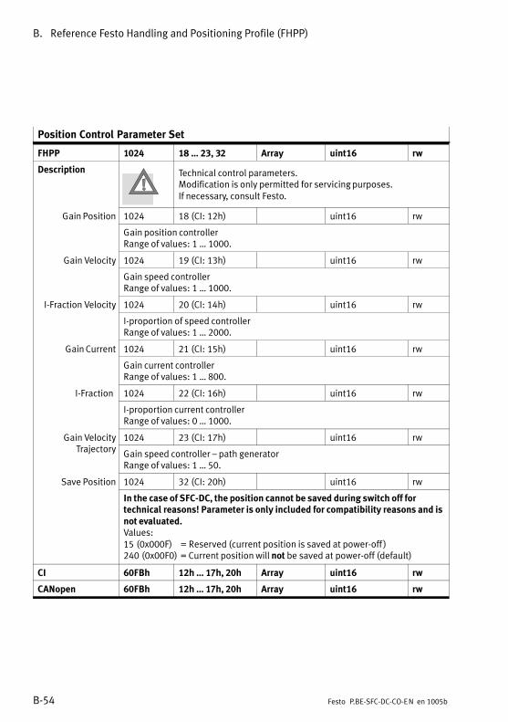
B. Reference Festo Handling and Positioning Profile (FHPP)
B−54 Festo P.BE−SFC−DC−CO−EN en 1005b
Position Control Parameter Set
FHPP 1024 18 � 23, 32 Array uint16 rw
Description Technical control parameters.Modification is only permitted for servicing purposes.If necessary, consult Festo.
Gain Position 1024 18 (CI: 12h) uint16 rw
Gain position controllerRange of values: 1 � 1000.
Gain Velocity 1024 19 (CI: 13h) uint16 rwy
Gain speed controllerRange of values: 1 � 1000.
I−Fraction Velocity 1024 20 (CI: 14h) uint16 rwy
I−proportion of speed controllerRange of values: 1 � 2000.
Gain Current 1024 21 (CI: 15h) uint16 rw
Gain current controllerRange of values: 1 � 800.
I−Fraction 1024 22 (CI: 16h) uint16 rw
I−proportion current controllerRange of values: 0 � 1000.
Gain Velocity 1024 23 (CI: 17h) uint16 rwyTrajectory Gain speed controller � path generator
Range of values: 1 � 50.
Save Position 1024 32 (CI: 20h) uint16 rw In the case of SFC−DC, the position cannot be saved during switch off fortechnical reasons! Parameter is only included for compatibility reasons and isnot evaluated.Values:15 (0x000F) = Reserved (current position is saved at power−off )240 (0x00F0) = Current position will not be saved at power−off (default)
CI 60FBh 12h � 17h, 20h Array uint16 rw
CANopen 60FBh 12h � 17h, 20h Array uint16 rw

B. Reference Festo Handling and Positioning Profile (FHPP)
B−55Festo P.BE−SFC−DC−CO−EN en 1005b
Motor Data
FHPP 1025 1, 3 Array uint32 rw
Description Motor−specific data
Serial Number 1025 1 uint32 rw Reserved (Serial number of the motor, written values are not adopted)
Time Max Current 1025 3 uint32 rw I2t time in 20 ms (device−specific with the SFC−DC). When the I2t time elapses,the current is limited automatically to the motor rated current in order toprotect the motor (Motor Rated Current, PNU�1035 / Object�6075h).Range of values: 1 � 32767Default: 100 (Z 2 s)
CI 6410h 01h, 03h Record uint32 rw
CANopen 6410h 01h, 03h Record uint32 rw
NoteThe duration of the maximum motor current has beenadjusted to the supported drives. Values that are too high can damage the motor.

B. Reference Festo Handling and Positioning Profile (FHPP)
B−56 Festo P.BE−SFC−DC−CO−EN en 1005b
Drive Data
FHPP 1026 1 � 8 Array uint32 ro/rw
Description General motor data
Output Stage Temp 1026 1 uint32 rop g p
Temperature of the output stage in °CRange of values: 0 � 85 (0x00 � 0x55)
Output stage 1026 2 uint32 rop gMax. Temp Maximum temperature of the output stage in °C
Fixed: 80 (0x0050)
Motor Rated 1026 3 uint32 roCurrent Rated motor current in mA
SLTE−10: 336SLTE−16: 1440HGPLE−14/GEH60: 1270HGPLE−25/GEH61: 2250DEF: 704Value is automatically entered when an axis type is selected (PNU 1005/4).
Current Limit 1026 4 uint32 ro
Maximum motor current, identical to PNU 1034
Lower Current Limit 1026 5 uint32 ro
Lower current limit value in 1/1000 of the rated motor current
I/O Control 1026 6 uint32 rw/
Selection of the interface (see also PNU 125 / object 207Dh)0: Control via HMI (control panel) or FCT, no control via field bus1: Control via field bus � control interface (default)
Controller Serialb
1026 7 uint32 roNumber Serial number of the controller in format 0xDDMYYSSS:
TT (day): 8 Bit: 0x01 � 0x1FM (month): 4 Bit: 0x1 � 0xCYY (year): 8 Bit: 0x00 � 0x63SSS (serial no.): 12 Bit: 0x001 � 0xFFF
Following Errord
1026 8 uint32 rwgWindow Message window for following error monitoring. Values:
0: Following error monitoring switched off1 � +(232 − 1): Permitted following error in increments

B. Reference Festo Handling and Positioning Profile (FHPP)
B−57Festo P.BE−SFC−DC−CO−EN en 1005b
Drive Data
CI 6510h 01h � Record ro/rw
CANopen 6510h 01h � Record ro/rw
Drive Data 1) 6510h 01h � 08h uint32 ro/rw 6510h 31h, 32h,
40h, 41h,42h, 43h,A0h, 22h
uint16, uint16,uint32, uint16,int16, uint16,uint32, uint32
ro, roro, roro, rwro, ro
Current Actuall
6510h 45h int 16 roValue
Actual value of the current.Note: Not available via FHPP.
Firmware Number 6510h A1h uint32 ro
Firmware version, specified in BCD (binary coded decimal): xxyy(xx = main version, yy = secondary version)Note: Identical to FHPP object PNU 101 (CI 206Ah)
1) Description similar to FHPP 1026/1 � 8. Subindices 31h � A0h are not available via FHPP

B. Reference Festo Handling and Positioning Profile (FHPP)
B−58 Festo P.BE−SFC−DC−CO−EN en 1005b
B.2.18 Axis parameters electric drive 1 � Electronics Name plate
Motor Type
FHPP 1030 � Var uint16 r
Description Classification of the motorFixed: 0x0000
CI 6402h 00h Var uint16 r
CANopen 6402h � Var uint16 rw
Maximum Current
FHPP 1034 � Var uint16 rw
Description Maximum motor current during homing in 1/1000 of the specified nominalcurrent (PNU 1035 / object 6075h).In homing (reference travel) mode: Setpoint value for the current regulator.Limits the motor force during homing to stops and, in the event of an error,protects the stops during homing to a reference switch.NoteObserve that the current limitation also limits the maximum possible speed andthat (higher) nominal speeds may not therefore be achieved.Range of values: 1 � 3000Default: 1000
CI 6073h 00h Var uint16 rw
CANopen 6073h � Var uint16 rw
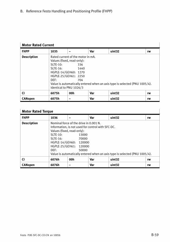
B. Reference Festo Handling and Positioning Profile (FHPP)
B−59Festo P.BE−SFC−DC−CO−EN en 1005b
Motor Rated Current
FHPP 1035 � Var uint32 rw
Description Rated current of the motor in mA.Values (fixed, read−only):SLTE−10: 336SLTE−16: 1440HGPLE−14/GEH60: 1270HGPLE−25/GEH61: 2250DEF: 704Value is automatically entered when an axis type is selected (PNU 1005/4).Identical to PNU 1026/3
CI 6075h 00h Var uint32 rw
CANopen 6075h � Var uint32 rw
Motor Rated Torque
FHPP 1036 � Var uint32 rw
Description Nominal force of the drive in 0.001 N. Information, is not used for control with SFC−DC.Values (fixed, read−only):SLTE−10: 13000SLTE−16: 70000HGPLE−14/GEH60: 120000HGPLE−25/GEH61: 120000DEF: 50000Value is automatically entered when an axis type is selected (PNU 1005/4).
CI 6076h 00h Var uint32 rw
CANopen 6076h � Var uint32 rw

B. Reference Festo Handling and Positioning Profile (FHPP)
B−60 Festo P.BE−SFC−DC−CO−EN en 1005b
B.2.19 Axis parameters electric drive 1 � Standstill monitoring
Position Target Value
FHPP 1040 � Var int32 ro
Description Target position of the last positioning job, in incrementsRange of values: −231 � +(231 − 1)
CI 6062h 00h Var int32 ro
CANopen 6062h � Var int32 ro
Position Actual Value
FHPP 1041 � Var int32 ro
Description Actual position of the drive in incrementsRange of values: −231 � +(231 − 1)
CI 6064h 00h Var int32 ro
CANopen 6064h � Var int32 ro
Standstill Position Window
FHPP 1042 � Var uint32 rw
Description Standstill position window in increments: Amount by which the drive may moveafter MC, until the standstill monitoring responds.Range of values: 0 � +(232 − 1)Default: 750 (approx. SLTE−10: 0.42 mm HGPLE−14/GEH60: 0.06 mm
SLTE−16: 0.32 mm HGPLE−25/GEH61: 0.14 mmDEF: 1,35°)
CI 2040h 00h Var uint32 rw
CANopen 2040h � Var uint32 rw

B. Reference Festo Handling and Positioning Profile (FHPP)
B−61Festo P.BE−SFC−DC−CO−EN en 1005b
Standstill Window Time
FHPP 1043 � Var uint16 rw
Description Standstill monitoring time in [ms]: Time during which the drive must be outsidethe standstill position window before the standstill monitoring responds.Range of values: 0 � 30000 (Z 0 � 30 s)Default: 200 (Z 0.2 s)
CI 2041h 00h Var uint16 rw
CANopen 2041h � Var uint16 rw

B. Reference Festo Handling and Positioning Profile (FHPP)
B−62 Festo P.BE−SFC−DC−CO−EN en 1005b

Reference CANopen and Command Interpreter (CI)
C−1Festo P.BE−SFC−DC−CO−EN en 1005b
Appendix C
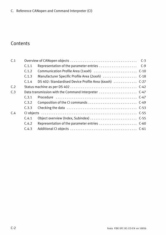
C. Reference CANopen and Command Interpreter (CI)
C−2 Festo P.BE−SFC−DC−CO−EN en 1005b
Contents
C.1 Overview of CANopen objects C−3 . . . . . . . . . . . . . . . . . . . . . . . . . . . . . . . . . . . . .
C.1.1 Representation of the parameter entries C−9 . . . . . . . . . . . . . . . . . . . . .
C.1.2 Communication Profile Area (1xxxh) C−10 . . . . . . . . . . . . . . . . . . . . . . . .
C.1.3 Manufacturer Specific Profile Area (2xxxh) C−18 . . . . . . . . . . . . . . . . . . .
C.1.4 DS 402: Standardised Device Profile Area (6xxxh) C−27 . . . . . . . . . . . . .
C.2 Status machine as per DS 402 C−42 . . . . . . . . . . . . . . . . . . . . . . . . . . . . . . . . . . . . .
C.3 Data transmission with the Command Interpreter C−47 . . . . . . . . . . . . . . . . . . . . .
C.3.1 Procedure C−47 . . . . . . . . . . . . . . . . . . . . . . . . . . . . . . . . . . . . . . . . . . . . .
C.3.2 Composition of the CI commands C−49 . . . . . . . . . . . . . . . . . . . . . . . . . . .
C.3.3 Checking the data C−53 . . . . . . . . . . . . . . . . . . . . . . . . . . . . . . . . . . . . . . .
C.4 CI objects C−55 . . . . . . . . . . . . . . . . . . . . . . . . . . . . . . . . . . . . . . . . . . . . . . . . . . . . .
C.4.1 Object overview (Index, Subindex) C−55 . . . . . . . . . . . . . . . . . . . . . . . . . .
C.4.2 Representation of the parameter entries C−60 . . . . . . . . . . . . . . . . . . . . .
C.4.3 Additional CI objects C−61 . . . . . . . . . . . . . . . . . . . . . . . . . . . . . . . . . . . . .

C. Reference CANopen and Command Interpreter (CI)
C−3Festo P.BE−SFC−DC−CO−EN en 1005b
C.1 Overview of CANopen objects
The following overview (Tab.�C/1) shows all CANopen objects,where appropriate with the corresponding FHPP numbers.
You will find the descriptions of the objects in the followingsection (see �See" column):
� Descriptions of CANopen objects in appendix C.1.2, C.1.3and C.1.4,
� Descriptions of the corresponding PNUs as per FHPP inappendix B.2.4 to B.2.19.
You will find a thematically grouped overview of the FHPPobjects in appendix B.2.2.
Name CANopen FHPP see
Object SI Class PNU
Communication Profile Area, see appendix C.1.2
Device Type 1000h � / 00h Var � C.1.2
Error Register
1001h � Var � C.1.2
Pre−defined Error Field
1003h 01 ... 08h Array � C.1.2
COB−ID SYNC Message 1005h � Var � C.1.2
Manufacturer Device Name 1008h � / 00h Var 120 B.2.5
Manufacturer Hardware Version 1009h � / 00h Var � C.1.2
Manufacturer software version 100Ah � / 00h Var � C.1.2
Guard Time 100Ch � Var � C.1.2
Life Time Factor 100Dh � Var � C.1.2

C. Reference CANopen and Command Interpreter (CI)
C−4 Festo P.BE−SFC−DC−CO−EN en 1005b
Name seeFHPPCANopenName see
PNUClassSIObject
COB−ID Emergency Object 1014h � Var � C.1.2
Inhibit Time EMCY 1015h � Var � C.1.2
Identity Object 1018h 01h ... 04h Record � C.1.2
Receive PDO Communication Parameter 1400h,1401h
01h ... 05h Record � C.1.2
Receive PDO 1 Mapping Parameter 1600h 01h ... 05h Record � C.1.2
Receive PDO 2 Mapping Parameter 1601h 01h ... 04h Record � C.1.2
Transmit PDO Communication Parameter
1800h,1801h
01h ... 05h Record � C.1.2
Transmit PDO 1 Mapping Parameter 1A00h 01h ... 05h Record � C.1.2
Transmit PDO 2 Mapping Parameter 1A01h 01h ... 04h Record � C.1.2
Manufacturer Specific Profile Area, see appendix C.1.3
Record Number 2032h 01h Array 2) − C.1.3
Standstill Position Window 2040h � / 00h Var 1042 B.2.19
Standstill Timeout 2041h � / 00h Var 1043 B.2.19
Version FHPP 2066h � / 00h Var 102 B.2.4
Manufacturer Hardware Version 2069h � / 00h Var 100 B.2.4
Manufacturer Software Version 206Ah � / 00h Var 101 B.2.4
Controller Serial Number 2072h � / 00h Var 114 B.2.4
Device Control 207Dh � / 00h Var 125 B.2.5
Diagnostic Event 20C8h 01h ... 10h Array 200 B.2.6

C. Reference CANopen and Command Interpreter (CI)
C−5Festo P.BE−SFC−DC−CO−EN en 1005b
Name seeFHPPCANopenName see
PNUClassSIObject
Fault Number 20C9h 01h ... 10h Array 201 B.2.6
Time Stamp 20CAh 01h ... 10h Array 202 B.2.6
Diagnosis Memory Parameter 20CCh 01h ... 04h Array 204 B.2.6
Scaling 20D0h 01h, 02h Array � C.1.3
Record Table Element 20E0h 01h ... 05h Record � C.1.3
Axis Parameter 20E2h 01h ... 05h Array 1005 B.2.15
Controller Type 20E3h � / 00h Var � C.1.3
Jog Mode Time Phase 1 20E9h 00h / 21h
Var / Array
534 B.2.12
Data Memory Control 20F1h 01h, 02h Array 127 B.2.5
User Device Name 20FDh � / 00h V−string 121 B.2.5
HMI Control 20FFh 01h ... 04h Array 126 B.2.5
Project Zero Point 21F4h � / 00h Var 500 B.2.9
Max. Velocity 21F6h � / 00h Var 502 B.2.9
Max. Acceleration 21F7h � / 00h Var 503 B.2.9
Teach Target 21FCh � / 00h Var 520 B.2.11
Homing Required 23F6h � / 00h Var 1014 B.2.16
Homing Max. Torque 23F7h � / 00h Var 1015 B.2.16
Device Fault 2FF1h � / 00h Var 205 B.2.6

C. Reference CANopen and Command Interpreter (CI)
C−6 Festo P.BE−SFC−DC−CO−EN en 1005b
Name seeFHPPCANopenName see
PNUClassSIObject
CANopen Diagnosis 2FF2h 01h ... 06h Array 206 B.2.6
Cycle Number 2FFFh � / 00h Var 305 B.2.7
DS 402: Standardised Device Profile Area, see C.1.4
Controlword DS 402 6040h � / 00h Var � C.1.4
Statusword DS 402)
6041h � / 00h Var � C.1.4
Halt Option Code 605Dh � / 00h Var 1020 B.2.17
Fault Reaction Option Code 605Eh � / 00h Var 1021 B.2.17
Modes of Operation 6060h � / 00h Var � C.1.4
Modes of Operation Display 6061h � / 00h Var � C.1.4
Position Demand Value 6062h � / 00h Var 1040 B.2.19
Position Actual Value* 6063h � / 00h Var � C.1.4
Position Actual Value 6064h � / 00h Var 1041 B.2.19
Position Window 6067h � / 00h Var 1022 B.2.17
Position Window Time 6068h � / 00h Var 1023 B.2.17
Velocity Demand Value 606Bh � / 00h Var � C.1.4
Velocity Actual Value 606Ch � / 00h Var � C.1.4
Target Torque 6071h � / 00h Var � C.1.4
Max. Current 6073h � / 00h Var 1034 B.2.18
Motor Rated Current 6075h � / 00h Var 1035 B.2.18

C. Reference CANopen and Command Interpreter (CI)
C−7Festo P.BE−SFC−DC−CO−EN en 1005b
Name seeFHPPCANopenName see
PNUClassSIObject
Motor Rated Torque 6076h � / 00h Var 1036 B.2.18
Torque Actual Value 6077h � / 00h Var � C.1.4
Target Position 607Ah � / 00h Var � C.1.4
Position Range Limit 607Bh 01h, 02h Array 501 B.2.9
Home Offset 607Ch � / 00h Var 1010 B.2.16
Polarity 607Eh � / 00h Var 1000 B.2.15
Profile Velocity 6081h � / 00h Var � C.1.4
Profile Acceleration 6083h � / 00h Var � C.1.4
Profile Deceleration 6084h � / 00h Var � C.1.4
Motion Profile Type 6086h � / 00h Var � C.1.4
Position Encoder Resolution 608Fh 01h, 02h Array 1001 B.2.15
Gear Ratio 6091h 01h, 02h Array 1002 B.2.15
Feed Constant 6092h 01h, 02h Array 1003 B.2.15
Position Factor 6093h 01h, 02h Array 1004 B.2.15
Homing Method 6098h � / 00h Var 1011 B.2.16
Homing Speeds 6099h 01h, 02h Array 1012 B.2.16
Torque Control Parameters (Force ...) 60F6h 01h ... 05h Array 510,511,552 ...554
B.2.10
B.2.14
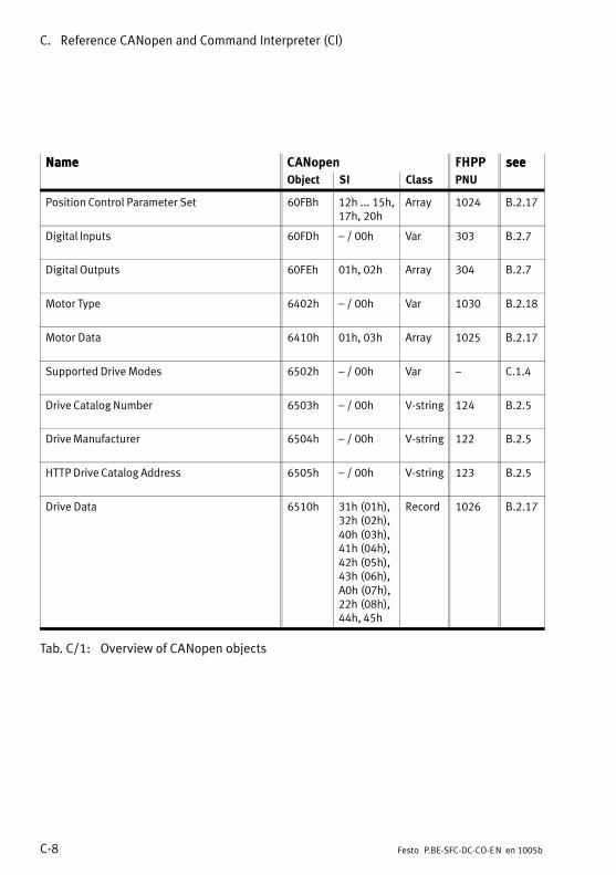
C. Reference CANopen and Command Interpreter (CI)
C−8 Festo P.BE−SFC−DC−CO−EN en 1005b
Name seeFHPPCANopenName see
PNUClassSIObject
Position Control Parameter Set 60FBh 12h ... 15h,17h, 20h
Array 1024 B.2.17
Digital Inputs 60FDh � / 00h Var 303 B.2.7
Digital Outputs 60FEh 01h, 02h Array 304 B.2.7
Motor Type 6402h � / 00h Var 1030 B.2.18
Motor Data 6410h 01h, 03h Array 1025 B.2.17
Supported Drive Modes 6502h � / 00h Var � C.1.4
Drive Catalog Number 6503h � / 00h V−string 124 B.2.5
Drive Manufacturer 6504h � / 00h V−string 122 B.2.5
HTTP Drive Catalog Address 6505h � / 00h V−string 123 B.2.5
Drive Data 6510h 31h (01h),32h (02h),40h (03h),41h (04h),42h (05h),43h (06h),A0h (07h),22h (08h),44h, 45h
Record 1026 B.2.17
Tab.�C/1: Overview of CANopen objects
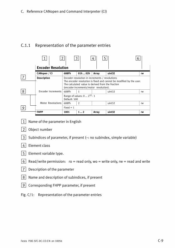
C. Reference CANopen and Command Interpreter (CI)
C−9Festo P.BE−SFC−DC−CO−EN en 1005b
C.1.1 Representation of the parameter entries
Encoder Resolution
CANopen / CI 608Fh 01h ... 02h Array uint32 rw
Description Encoder resolution in increments / revolutionsThe encoder resolution is fixed and cannot be modified by the user.The�calculated value is derived from the fraction(encoder�increments/motor revolution).
Encoder Increments 608Fh 1 uint32 rw
Range of values: 0 ... 232 − 1Default: 500
Motor Revolutions 608Fh 2 uint32 rw
Fixed = 1
FHPP 1001 1 ... 2 Array uint32 rw
1 Name of the parameter in English
2 Object number
3 Subindices of parameter, if present (�: no subindex, simple variable)
4 Element class
5 Element variable type.
6 Read/write permission: ro = read only, wo = write only, rw = read and write
7 Description of the parameter
8 Name and description of subindices, if present
9 Corresponding FHPP parameter, if present
Fig.�C/1: Representation of the parameter entries
1 2 3 4 5 6
7
8
9

C. Reference CANopen and Command Interpreter (CI)
C−10 Festo P.BE−SFC−DC−CO−EN en 1005b
C.1.2 Communication Profile Area (1xxxh)
Device Type
CANopen / CI 1000h � / 00h Var uint32 ro
Description Classification of the device type and the function.Bit: 31 ... 16 15 ... 0Additional information Device profile number
Values dependent on data profile (object 2FF2h/05h / PNU 206):Device profile number: DS 402: 402 (0x0192)
FHPP: 301 (0x012d)Additional information: DS 402: 2 (0x0002) � Type code for servo drive
FHPP: 0 (0x0000) � not used
Error Register
CANopen 1001h � Var uint8 ro
Description Internal errors are stored in the error register. The error register is part of the emergency object.Bit: Description0 Generic error: error present (logical Or linking of bits 1 to 7)1 Current: Overload current on motor2 Voltage: voltage monitoring error3 Temperature: Motor over−temperature4 Communication error (overrun, error state)5 device profile specific: Bit 13 of status register (object 6041h)
Coding is mode−specific: Following error in positioning mode, homing error in homing mode
6 Reserved, fix = 07 manufacturer specific: Other serious errors, e.g. defective position
transmitter, invalid record list, limit switch monitoring etc.Values: 0 = no error; 1 = error.

C. Reference CANopen and Command Interpreter (CI)
C−11Festo P.BE−SFC−DC−CO−EN en 1005b
Pre−defined Error Field
CANopen 1003h 00h ... 08h Array uint32 rw/ro
Description Error memory for emergency object.The object stores the errors reported by way of the emergency object.Each�new error is stored in subindex 01h; the previous errors move onesubindex down each time a new one is added.
Number of Errors 1003h 00h uint32 rw Number of recorded errors as from subindex 01h.Value range 0 ... 8The error field can be cleared by writing �0".
Standard Errorld
1003h 01h uint32 roField Last stored error.
The error numbers comprise 16 bits of error code (lower 2 bytes � LSB,see�chapter 6.5.2, error code in Tab.�6/12) and 16 bits of additional information(upper 2 bytes � MSB, for SFC−DC = 0).
Standard Errorld
1003h 02h ... 08h uint32 roField Previously stored errors.
See subindex 01h.
COB−ID SYNC Message
CANopen 1005h � Var uint32 rw
Description COB ID of synchronisation object (SYNC); see DS 301 specification.Synchronous transfer can be set if the entries in the communication parametersof the PDOs are modified. For this an entry to this object by the master isessential; see DS 301 specification.Default: 128 (0x00000080)
Manufacturer Device Name
CANopen / CI 1008h � / 00h Var V−string ro
FHPP 120 1 ... 25 Array char ro
Description Designation of the drive.Example: �SFC−DC−VC−3−E−H2−CO" or �SFC−DC−VC−3−E−H0−CO"

C. Reference CANopen and Command Interpreter (CI)
C−12 Festo P.BE−SFC−DC−CO−EN en 1005b
Manufacturer Hardware Version
CANopen / CI 1009h � / 00h Var V−string ro
Description Coding of the hardware version (xx = main version, yy = secondary version).Format = �Vxx.yy"
Compare PNU 100 / object 2069h
Manufacturer Software Version
CANopen / CI 100Ah � / 00h Var V−string ro
Description Coding of the firmware version (xx = main version, yy = secondary version).Format = �Vxx.yy"
Compare PNU 101 / object 206Ah
Guard Time
CANopen 100Ch � Var uint16 rw
Description Guard time in ms.To define the Life Time for the Life Guarding Protocol the guard time in ms ismultiplied by the Life Time Factor (object 100Dh).Default: 0 (monitoring switched off )Range of values: 0 ... 32767 (0x0000 ... 0x7FFF)
Life Time Factor
CANopen 100Dh � Var uint8 rw
Description Multiplication factor for the guard time (object 100Ch).Default: 0Range of values: 0 ... 255 (0x00 ... 0xFF)
COB−ID Emergency Object
CANopen 1014h � Var uint32 rw
Description COB ID of emergency object (EMCY); see DS 301 specification.The emergency protocol is supported.Default: 128 + Node ID (0x80 + Node ID)

C. Reference CANopen and Command Interpreter (CI)
C−13Festo P.BE−SFC−DC−CO−EN en 1005b
Inhibit Time EMCY
CANopen 1015h � Var uint16 rw
Description Inhibit time for the emergency message.The value is multiplied by 100 ìs.Default: 0
Identity Object
CANopen 1018h 01h ... 04h Record uint32 ro
Description Device identification
Vendor ID 1018h 01h uint32 ro Manufacturer identifier for Festo.Fixed: 29 (0x0000001d)
Product code 1018h 02h uint32 ro
Product codeFixed: 540364 (HO) or 540365 (H2)
Revision Number 1018h 03h uint32 ro
Firmware version, e.g. 0x0001000A for version 1.10
Serial Number 1018h 04h uint32 ro
See object 6510/07h or 6510/A0h.

C. Reference CANopen and Command Interpreter (CI)
C−14 Festo P.BE−SFC−DC−CO−EN en 1005b
Receive PDO Communication Parameter
CANopen 1400h,1401h
01h ... 05h Record uint32, uint8, uint16 rw
Description Communication parameters of PDOs 1 and 2 which the device can receive:� PDO 1: Object 1400h� PDO 2: Object 1401h
COB ID for PDO 1400h,1401h
01h uint32 rw
COB ID used by the PDO.� PDO 1: Default: 0x200 + Node ID� PDO 2: Default: 0x300 + Node ID
Transmission Type 1400h,1401h
02h uint8 rw
Transmission typeDefault: 255 (0xFF) � Event−triggered asynchronous transmissionRange of values: 0 ... 255 (0x00 ... 0xFF)
Inhibit Time 1400h,1401h
03h uint16 rw
Inhibit time, not used for RPDO.Fixed: 0 (0x0000)
Compatibility Entry(reserved)
1400h,1401h
04h � �( )
Reserved, must not be implemented (access attempts are answered with abortcode).
Event Timer 1400h,1401h
05h uint16 rw
Event counter in [ms].Default: 0 (0x0000)
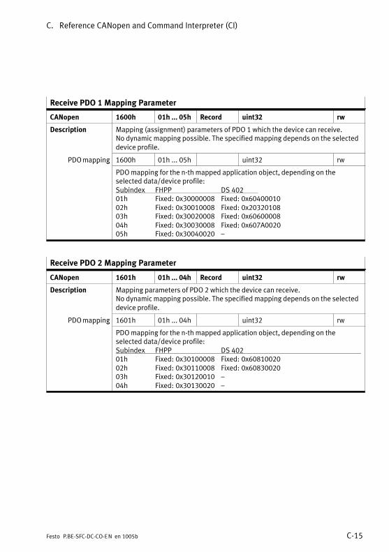
C. Reference CANopen and Command Interpreter (CI)
C−15Festo P.BE−SFC−DC−CO−EN en 1005b
Receive PDO 1 Mapping Parameter
CANopen 1600h 01h ... 05h Record uint32 rw
Description Mapping (assignment) parameters of PDO 1 which the device can receive.No dynamic mapping possible. The specified mapping depends on the selecteddevice profile.
PDO mapping 1600h 01h ... 05h uint32 rwpp g
PDO mapping for the n−th mapped application object, depending on theselected data/device profile:Subindex FHPP DS 40201h Fixed: 0x30000008 Fixed: 0x6040001002h Fixed: 0x30010008 Fixed: 0x2032010803h Fixed: 0x30020008 Fixed: 0x6060000804h Fixed: 0x30030008 Fixed: 0x607A002005h Fixed: 0x30040020 �
Receive PDO 2 Mapping Parameter
CANopen 1601h 01h ... 04h Record uint32 rw
Description Mapping parameters of PDO 2 which the device can receive.No dynamic mapping possible. The specified mapping depends on the selecteddevice profile.
PDO mapping 1601h 01h ... 04h uint32 rwpp g
PDO mapping for the n−th mapped application object, depending on theselected data/device profile:Subindex FHPP DS 40201h Fixed: 0x30100008 Fixed: 0x6081002002h Fixed: 0x30110008 Fixed: 0x6083002003h Fixed: 0x30120010 �04h Fixed: 0x30130020 �

C. Reference CANopen and Command Interpreter (CI)
C−16 Festo P.BE−SFC−DC−CO−EN en 1005b
Transmit PDO Communication Parameter
CANopen 1800h,1801h
01h ... 05h Record uint32, uint8, uint16 rw
Description Communication parameters of PDOs 1 and 2 which the device can transmit:� PDO 1: Object 1800h� PDO 2: Object 1801h
COB ID for PDO 1800h,1801h
01h uint32 rw
COB ID used by the PDO.� PDO 1: Default: 0x180 + Node ID� PDO 2: Default: 0x280 + Node ID
Transmission Type 1800h,1801h
02h uint8 rw
Transmission typeDefault: 255 (0xFF) � Event−triggered asynchronous transmissionRange of values: 0 ... 255 (0x00 ... 0xFF)
Inhibit Time 1800h,1801h
03h uint16 rw
Inhibit time.Fixed: 0 (0x0000)
Compatibility Entry(reserved)
1800h,1801h
04h � �( )
Reserved, must not be implemented(access�attempts�are�answered�with�abort�code).
Event Timer 1800h,1801h
05h uint16 rw
Event counter in [ms].Default: 0 (0x0000)

C. Reference CANopen and Command Interpreter (CI)
C−17Festo P.BE−SFC−DC−CO−EN en 1005b
Transmit PDO 1 Mapping Parameter
CANopen 1A00h 01h ... 05h Record uint32 rw
Description Mapping (assignment) parameters of PDO 1 which the device can transmit.No dynamic mapping possible. The specified mapping depends on the selecteddevice profile.
PDO mapping 1A00h 01h ... 05h uint32 rwpp g
PDO mapping for the n−th mapped application object, depending on theselected data/device profile:Subindex FHPP DS 40201h Fixed: 0x30200008 Fixed: 0x6041001002h Fixed: 0x30210008 Fixed: 0x2032010803h Fixed: 0x30220008 Fixed: 0x6061000804h Fixed: 0x30230008 Fixed: 0x6064002005h Fixed: 0x30240020 �
Transmit PDO 2 Mapping Parameter
CANopen 1A01h 01h ... 04h Record uint32 rw
Description Mapping (assignment) parameters of PDO 1 which the device can transmit.No dynamic mapping possible. The specified mapping depends on the selecteddevice profile.
PDO mapping 1A01h 01h ... 04h uint32 rwpp g
PDO mapping for the n−th mapped application object, depending on theselected data/device profile:Subindex FHPP DS 402 (not used)01h Fixed: 0x30300008 Fixed: 0x6041001002h Fixed: 0x30310008 Fixed: 0x2032010803h Fixed: 0x30320008 Fixed: 0x6061000804h Fixed: 0x30330008 Fixed: 0x60640020

C. Reference CANopen and Command Interpreter (CI)
C−18 Festo P.BE−SFC−DC−CO−EN en 1005b
C.1.3 Manufacturer Specific Profile Area (2xxxh)
Record Number
CANopen / CI 2032h 01h Array 1) uint8 rwp /
1) Pseudo−array for compatibility
Description Select a position record via the record number.The record number is saved as the target for write and read operations on thefollowing Objects:� object 20E0/01h ... 05h: position_table_element� or objects 607Ah, 6081h, 6083h, 6084h.There is a direct correlation with object 2033h (PNU 401).
Record Number 2032h 01h uint8 rw
Read or write record number.Values:0 (0x00): DS 402 Direct positioning (do not use with FHPP)1 (0x00): reserved, do not use (CANopen RS232 position record)2 (0x02): Homing (position record 0)3 (0x03): Position record 1 (default)4 (0x04): Position record 2... Positioning record ...33 (0x21): Position record 31
Recordnumber
SFC−DC
2032hRecordno.uint8
20E0/01hRCB1
uint8
20E0/02hSetpointpos.int32
20E0/03hVelocity
uint32
20E0/04hAcc. Movement to
uint32
20E0/05hAcc. Brake
uint32
0 2 Homing
1 3 ... ... ... ... ...
2 4 ... ... ... ... ...
... ... ... ... ... ... ...
31 33 ... ... ... ... ...
Tab.�C/2: Structure of DS 402 record list
For DS 402 the record is selected with object 2032h.The�selected record is then addressed with object 20E0h,with the record element (column in Tab.�C/2) being selectedwith the subindex. 2 is deducted from the value received viaobject 2032h in order to get the internal record number.

C. Reference CANopen and Command Interpreter (CI)
C−19Festo P.BE−SFC−DC−CO−EN en 1005b
Standstill Position Window
CANopen / CI 2040h � / 00h Var uint32 rw
Description See PNU 1042, appendix B.2.19.
FHPP 1042 � Var uint32 rw
Standstill Window Time
CANopen / CI 2041h � / 00h Var uint16 rw
Description See PNU 1043, appendix B.2.19.
FHPP 1043 � Var uint16 rw
Version FHPP
CANopen / CI 2066h � / 00h Var uint16 ro
Description Version number of the FHPP, see PNU 102, appendix B.2.4.
FHPP 102 � Var uint16 ro
Manufacturer Hardware Version
CANopen / CI 2069h � / 00h Var uint16 ro
Description Coding of the hardware version, see PNU 100, appendix B.2.4.see Object 1009h
FHPP 100 � Var uint16 ro
Manufacturer Firmware Version
CANopen / CI 206Ah � / 00h Var uint16 ro
Description Coding of the firmware version, see PNU 101, appendix B.2.4.Compare Object 100Ah
FHPP 101 � Var uint16 ro
Controller Serial Number
CANopen / CI 2072h � / 00h Var V−string ro
Description 12−position code for clearly identifying the controller.Example: �TD15P0212345"
FHPP 114 1 ... 12 Array char ro
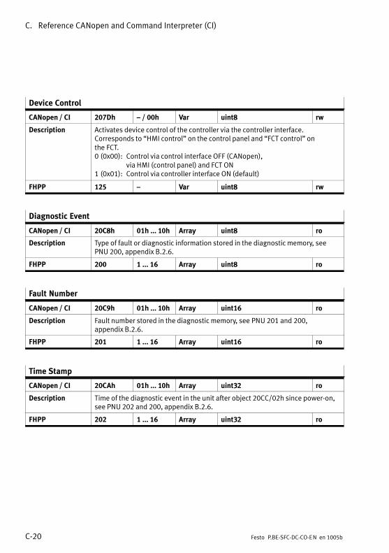
C. Reference CANopen and Command Interpreter (CI)
C−20 Festo P.BE−SFC−DC−CO−EN en 1005b
Device Control
CANopen / CI 207Dh � / 00h Var uint8 rw
Description Activates device control of the controller via the controller interface.Corresponds to �HMI control" on the control panel and �FCT control" onthe�FCT.0 (0x00): Control via control interface OFF (CANopen),
via HMI (control panel) and FCT ON1 (0x01): Control via controller interface ON (default)
FHPP 125 � Var uint8 rw
Diagnostic Event
CANopen / CI 20C8h 01h ... 10h Array uint8 ro
Description Type of fault or diagnostic information stored in the diagnostic memory, seePNU 200, appendix B.2.6.
FHPP 200 1 ... 16 Array uint8 ro
Fault Number
CANopen / CI 20C9h 01h ... 10h Array uint16 ro
Description Fault number stored in the diagnostic memory, see PNU 201 and 200,appendix�B.2.6.
FHPP 201 1 ... 16 Array uint16 ro
Time Stamp
CANopen / CI 20CAh 01h ... 10h Array uint32 ro
Description Time of the diagnostic event in the unit after object 20CC/02h since power−on,see PNU 202 and 200, appendix B.2.6.
FHPP 202 1 ... 16 Array uint32 ro

C. Reference CANopen and Command Interpreter (CI)
C−21Festo P.BE−SFC−DC−CO−EN en 1005b
Diagnosis Memory Parameter
CANopen / CI 20CCh 01h ... 04h Array uint8 rw/ro
Description Configuration of the diagnostic memory, see PNU 204, appendix B.2.6.
Fault Type 20CCh 01h uint8 rwyp
Incoming and outgoing malfunctions.
Resolution 20CCh 02h uint8 rw
Resolution time stamp
Clear Memory 20CCh 03h uint8 rwy
Clear diagnostic memory by writing value = 1.
Number of Entries 20CCh 04h uint8 ro
Read out the number of valid entries in the diagnostic memory.
FHPP 204 1 ... 4 Array uint8 rw/ro
Scaling
CANopen / CI 20D0h 01h, 02h Array uint8 rw/ro
Description Measuring units and scalingDefinition of the system of measurement used for displaying the values on thecontrol panel and the number (n) of places after the decimal point.
Measuring Unit 20D0h 01h uint8 rwg
Definition of unit of measurement.The setting for the system of measurement only affects the display. Allparameters are always saved in increments in the controller and are notconverted into the relevant measuring system until they are written ordownloaded.Values:1 (0x01): Metric measuring units: e.�g. mm, mm/s, mm/s2
2 (0x02): Reserved4 (0x04): Reserved8 (0x08): Reserved15 (0x0F): Reserved
Scaling Factor 20D0h 02h uint8 rog
Number of positions after the decimal point (n)Range of values: 0 ... 4 (0x00 ... 0x04)Fixed: 2 (cannot be set for SFC−DC−CO)
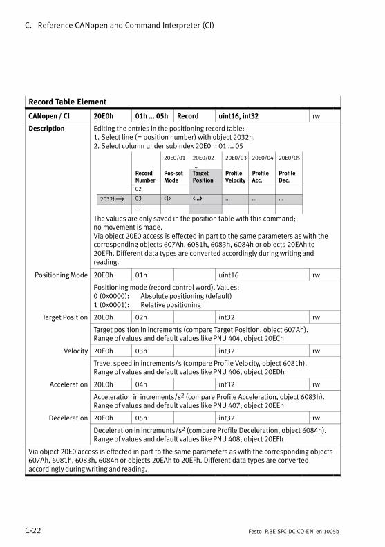
C. Reference CANopen and Command Interpreter (CI)
C−22 Festo P.BE−SFC−DC−CO−EN en 1005b
Record Table Element
CANopen / CI 20E0h 01h ... 05h Record uint16, int32 rw
Description Editing the entries in the positioning record table:1. Select line (= position number) with object 2032h.2. Select column under subindex 20E0h: 01 ... 05
20E0/01 20E0/02V
20E0/03 20E0/04 20E0/05
Record Number
Pos−setMode
TargetPosition
ProfileVelocity
ProfileAcc.
ProfileDec.
02
2032h} 03 <1> <...> ... ... ...
...
The values are only saved in the position table with this command;no�movement is made.Via object 20E0 access is effected in part to the same parameters as with thecorresponding objects 607Ah, 6081h, 6083h, 6084h or objects 20EAh to20EFh. Different data types are converted accordingly during writing andreading.
Positioning Mode 20E0h 01h uint16 rwg
Positioning mode (record control word). Values:0 (0x0000): Absolute positioning (default)1 (0x0001): Relative positioning
Target Position 20E0h 02h int32 rwg Target position in increments (compare Target Position, object 607Ah).Range of values and default values like PNU 404, object 20ECh
Velocity 20E0h 03h int32 rwy
Travel speed in increments/s (compare Profile Velocity, object 6081h).Range of values and default values like PNU 406, object 20EDh
Acceleration 20E0h 04h int32 rw
Acceleration in increments/s2 (compare Profile Acceleration, object 6083h).Range of values and default values like PNU 407, object 20EEh
Deceleration 20E0h 05h int32 rw
Deceleration in increments/s2 (compare Profile Deceleration, object 6084h).Range of values and default values like PNU 408, object 20EFh
Via object 20E0 access is effected in part to the same parameters as with the corresponding objects607Ah, 6081h, 6083h, 6084h or objects 20EAh to 20EFh. Different data types are convertedaccordingly during writing and reading.

C. Reference CANopen and Command Interpreter (CI)
C−23Festo P.BE−SFC−DC−CO−EN en 1005b
Axis Parameter
CANopen / CI 20E2h 01h ... 05h Record uint32 rw
Description Specify and read axis parameters e.g. for diagnosis, see PNU 1005,appendix�B.2.15
Axis Length 20E2h 01h uint32 rwg Axis length in increments.
Gear Numerator 20E2h 02h uint32 rw
Gear ratio � numerator, reserved for future extensions.
Gear Denominator 20E2h 03h uint32 rw
Gear ratio � denominator, reserved for future extensions.
Axis Type 20E2h 04h uint32 rwyp
Axis or gripper type.
Axis Size 20E2h 05h uint32 rw
For mini slides the slide length, for grippers the stroke (the �size"), for rotarymodules a fixed value.
FHPP 1005 1 ... 5 Array uint32 rw
Controller Type
CANopen / CI 20E3h � Var uint8 rw
Description Type of controller.Values:0 (0x00): Controller with display/keyboard (type ...−H2−...)1 (0x01): Controller without display/keyboard (type ...−H0−...)3 ... 15: cannot be set (reserved for future extensions)
Jog Mode Time Phase 1
CANopen / CI 20E9h 1) uint32 rwp /
1) Subindex depends on pre−set data profile (object 2FF2h/05h / PNU 206):� DS 402: 20E9/00h � Var� FHPP: 20E9/21h � Array
Description Time period of phase 1 (T1) in ms, see PNU 534, appendix B.2.12.
FHPP 534 � Var uint32 rw

C. Reference CANopen and Command Interpreter (CI)
C−24 Festo P.BE−SFC−DC−CO−EN en 1005b
Data Memory Control
CANopen / CI 20F1h 01h, 02h Array uint8 rw
Description Commands for the EEPROM (non−volatile data storage).Pay attention to the warnings under PNU 127, appendix B.2.5!
Delete EEPROM 20F1h 01h uint8 rw
Delete data in EEPROM.
Save Data 20F1h 02h uint8 rw
Overwrite data in EEPROM with the current settings.
FHPP 127 1, 2 Array uint8 rw
User Device Name
CANopen / CI 20FDh � / 00h Var V−string rw
Description User’s designation of the drive, see PNU 121, appendix B.2.5.
FHPP 121 1 ... 25 Array char rw
HMI Control
CANopen / CI 20FFh 01h ... 04h Array uint8 rw
Description Parametrisation of MMI functions (only for SFC−DC−...−H2−...),see�PNU�126,�appendix B.2.5.
LCD Current 20FFh 01h uint8 rw
Current setting.
LCD Contrast 20FFh 02h uint8 rw
Contrast setting.
Measure 20FFh 03h uint8 rw
Defining the system of measurement units for the LCD display
Scaling Factor 20FFh 04h uint8 rwg
Number of post−decimal positions
FHPP 126 1 ... 4 Array uint8 rw

C. Reference CANopen and Command Interpreter (CI)
C−25Festo P.BE−SFC−DC−CO−EN en 1005b
Project Zero Point
CANopen / CI 21F4h � / 00h Var int32 rw
Description Offset axis zero point � project zero point, see PNU 500, appendix B.2.9.
FHPP 500 � Var int32 rw
Max. Velocity
CANopen / CI 21F6h � / 00h Var uint32 rw
Description Max. permissible speed in increments/s, see PNU 502, appendix B.2.9.
FHPP 502 � Var uint32 rw
Max. Acceleration
CANopen / CI 21F7h � / 00h Var uint32 rw
Description Max. permissible acceleration in increments/s2, see PNU 503, appendix B.2.9.
FHPP 503 � Var uint32 rw
Teach Target
CANopen / CI 21FCh � / 00h Var uint8 rw
Description The parameter defined is the one which is written with the actual position withthe next Teach command, see PNU 520, appendix B.2.11.
FHPP 520 � Var uint8 rw
Homing Required
CANopen / CI 23F6h � / 00h Var uint8 rw
Description Defines whether or not homing must be carried out after power−on in order toexecute positioning tasks, see PNU 1014, appendix B.2.16.For the SLTE homing must always be performed after power−on!
FHPP 1014 � Var uint8 rw
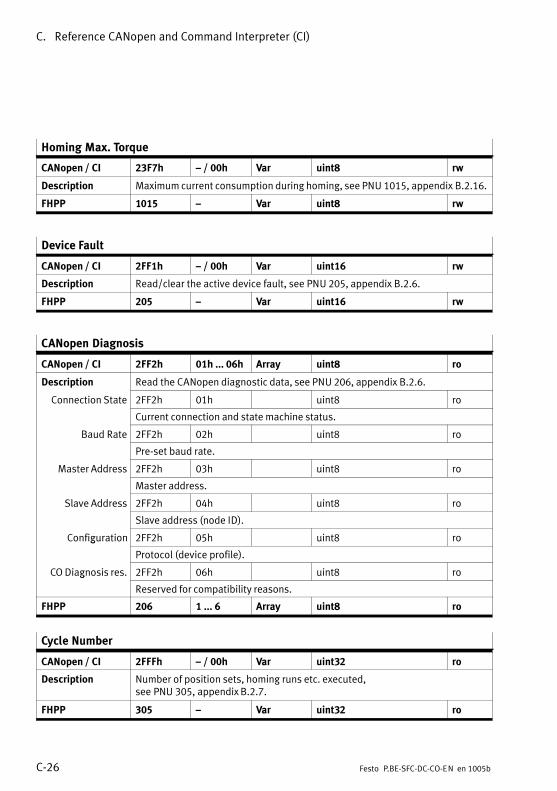
C. Reference CANopen and Command Interpreter (CI)
C−26 Festo P.BE−SFC−DC−CO−EN en 1005b
Homing Max. Torque
CANopen / CI 23F7h � / 00h Var uint8 rw
Description Maximum current consumption during homing, see PNU 1015, appendix B.2.16.
FHPP 1015 � Var uint8 rw
Device Fault
CANopen / CI 2FF1h � / 00h Var uint16 rw
Description Read/clear the active device fault, see PNU 205, appendix B.2.6.
FHPP 205 � Var uint16 rw
CANopen Diagnosis
CANopen / CI 2FF2h 01h ... 06h Array uint8 ro
Description Read the CANopen diagnostic data, see PNU 206, appendix B.2.6.
Connection State 2FF2h 01h uint8 ro
Current connection and state machine status.
Baud Rate 2FF2h 02h uint8 ro Pre−set baud rate.
Master Address 2FF2h 03h uint8 ro Master address.
Slave Address 2FF2h 04h uint8 ro Slave address (node ID).
Configuration 2FF2h 05h uint8 rog Protocol (device profile).
CO Diagnosis res. 2FF2h 06h uint8 rog
Reserved for compatibility reasons.
FHPP 206 1 ... 6 Array uint8 ro
Cycle Number
CANopen / CI 2FFFh � / 00h Var uint32 ro
Description Number of position sets, homing runs etc. executed,see�PNU�305,�appendix�B.2.7.
FHPP 305 � Var uint32 ro

C. Reference CANopen and Command Interpreter (CI)
C−27Festo P.BE−SFC−DC−CO−EN en 1005b
C.1.4 DS 402: Standardised Device Profile Area (6xxxh)
Controlword DS 402
CANopen / CI 6040h � / 00h Var uint16 rw
Description Modify the current controller status or trigger an activity.As changes of state take a certain amount of time, state changes triggered viathe control word must be read back via the status word. Only when therequested status can be read in the status word may a further command bewritten via the control word. For a description of the finite state machinesee�appendix C.2.Values see Tab.�C/3.Specific features when accessing via CI see appendix C.3.
Bit Value Description
0 0x0001 Switch on Control of state transitions.Th bit l t d t th1 0x0002 Enable Voltage These bits are evaluated together.
2 0x0004 Quick stop � low−active!
3 0x0008 Enable Operation
4 0x0010 Depends on operating mode (object 6060h):� Homing mode: Homing Operation Start (start reference travel)� Profile Position Mode: New Setpoint (move to position)
5 0x0020 Depends on operating mode (object 6060h):� Homing Mode: Reserved (set to 0)� Profile Position Mode: Reserved (change_set_immediately
not supported in record select and direct mode)
6 0x0040 Depends on operating mode (object 6060h):� Profile Position Mode: Absolute / relative� Homing Mode: Reserved (set to 0)
7 0x0080 Fault Reset (reset error)
8 0x0100 Halt as per Halt Option Code � object 605Dh.
9 0x0200 Reserved (= 0)
10 0x0400 Reserved (= 0)
11 0x0800 Jog positive: Run as long as set
12 0x1000 Jog negative: Run as long as set
13 0x2000 Teach: Apply current value
14 0x4000 HMI Access locked
15 0x8000 Symmetrical ramp transfer via PDO, i.e. acceleration value also for braking.Not�when accessing via SDO or the FCT.
Tab.�C/3: Description of control word

C. Reference CANopen and Command Interpreter (CI)
C−28 Festo P.BE−SFC−DC−CO−EN en 1005b
Statusword DS 402
CANopen / CI 6041h � / 00h Var uint16 ro
Description Reading the current controller or regulator status. For a description of the finite state machine see appendix C.2.Values see Tab.�C/4.Specific features when accessing via CI see appendix C.3.
Bit Value Description
0 0x0001 Ready to switch on Bits 0 ... 3, 5 and 6 show the status of the device(x irrelevant for this status)
1 0x0002 Switched on(x ... irrelevant for this status)Value (binary) Status
2 0x0004 Operation enabled
Value (binary) Statusxxxx xxxx x0xx 0000 Not ready to switch onxxxx xxxx x1xx 0000 Switch on disabled
3 0x0008 Faultxxxx xxxx x1xx 0000 Switch on disabledxxxx xxxx x01x 0001 Ready to switch on
01 0011 Switched on4 0x0010 Voltage enabled
xxxx xxxx x01x 0011 Switched onxxxx xxxx x01x 0111 Operation enabled
5 0x0020 Quick Stop
xxxx xxxx x01x 0111 Operation enabledxxxx xxxx x00x 0111 Quick stop activexxxx xxxx x0xx 1111 Fault reaction active
6 0x0040 Switch on disabledxxxx xxxx x0xx 1111 Fault reaction activexxxx xxxx x0xx 1000 Fault
7 0x0080 Warning (simple fault which does not require an emergency stop)
8 0x0100 Drive moves (corresponds to bit 4 of SPOS in FHPP)
9 0x0200 Remote (corresponding to bit 5 of SCON in FHPP)
10 0x0400 Target reached (see also objects 6067 and 6068)
11 0x0800 Internal limit active
12 0x1000 Depends on operating mode (object 6060):� Profile position mode: Setpoint acknowledge� Homing mode: Homing attained
13 0x2000 Depends on operating mode (object 6060):� Profile position mode: Following error� Homing mode: Homing error
14 0x4000 Teach acknowledge (corresponding to bit 3 of SPOS in FHPP)
15 0x8000 Homing performed (corresponding to bit 7 of SPOS in FHPP)
Tab.�C/4: Description of status word

C. Reference CANopen and Command Interpreter (CI)
C−29Festo P.BE−SFC−DC−CO−EN en 1005b
Halt Option Code
CANopen / CI 605Dh � / 00h Var uint16 rw
Description Describes the response to a Halt command, see PNU 1020, appendix B.2.17.
FHPP 1020 � Var uint16 rw
Fault Reaction Option Code
CANopen / CI 605Eh � / 00h Var uint16 rw
Description Describes the reaction to a fault, see PNU 1021, appendix B.2.17.
FHPP 1021 � Var uint16 rw
Modes of Operation
CANopen / CI 6060h � / 00h Var int8 rw
Description Set the controller operating mode.Values:−2 (0xFE): Demo mode (fixed sequence)1 (0x01): Profile position mode (default, position controller with
positioning�mode)3 (0x03): Reserved4 (0x04): Torque Mode (force mode)6 (0x06): Homing mode
Modes of Operation Display
CANopen / CI 6061h � / 00h Var int8 ro
Description Read current controller operating mode.Values see object 6060h.
Position Demand Value (setpoint position)
CANopen / CI 6062h � / 00h Var int32 ro
Description Setpoint target position of the last positioning task in increments,see�PNU�1040, appendix B.2.19.
FHPP 1040 � Var int32 ro
In FHPP: Position target value

C. Reference CANopen and Command Interpreter (CI)
C−30 Festo P.BE−SFC−DC−CO−EN en 1005b
Position Actual Value*
CANopen / CI 6063h � / 00h Var int32 ro
Description Current position of the drive in increments (encoder increments).Range of values: −231 ... +(231 − 1)
*: Normalised value
Position Actual Value
CANopen / CI 6064h � / 00h Var int32 ro
Description Current position of the drive in increments, see PNU 1041, appendix B.2.19.
FHPP 1041 � Var int32 ro
Position Window
CANopen / CI 6067h � / 00h Var uint32 rw
Description Tolerance window in increments, see PNU 1022, appendix B.2.17.
FHPP 1022 � Var uint32 rw
Position Window Time
CANopen / CI 6068h � / 00h Var uint16 rw
Description Adjustment time in milliseconds, see PNU 1022, appendix B.2.17.
FHPP 1023 � Var uint16 rw
Velocity Demand Value
CANopen / CI 606Bh � / 00h Var int32 ro
Description Current speed setpoint value of the speed regulator in increments.Setpoint speed for the current positioning operation calculated by thetrajectory generator. With this object the current setpoint speed of the speedregulator can be read. It is acted upon by the setpoint value of the ramp andcurve generators. Because the position controller is active in Profile PositionMode, its correction speed is also added in.Range of values: −231 ... +(231 − 1)

C. Reference CANopen and Command Interpreter (CI)
C−31Festo P.BE−SFC−DC−CO−EN en 1005b
Velocity Actual Value
CANopen / CI 606Ch � / 00h Var int32 ro
Description Current speed setpoint value of speed regulator in increments.Range of values: −231 ... +(231 −1)
Target Torque
CANopen / CI 6071h � / 00h Var int32 ro
Description Setpoint value for force mode. Specified in 1/1000 of the nominal value(6076h).
Max. Current
CANopen / CI 6073h � / 00h Var uint16 rw
Description Maximum motor current in 1/1000 of the specified rated current(object�6075h), see PNU 1034, appendix B.2.18.
FHPP 1034 � Var uint16 rw
Motor Rated Current
CANopen / CI 6075h � / 00h Var uint32 rw
Description Rated current of the motor, see PNU 1035, appendix B.2.18.
FHPP 1035 � Var uint32 rw
Motor Rated Torque
CANopen / CI 6076h � / 00h Var uint32 rw
Description Rated torque/force of the motor, see PNU 1036, appendix B.2.18.
FHPP 1036 � Var uint32 rw
Torque Actual Value
CANopen / CI 6077h � / 00h Var int32 ro
Description Actual value in force mode. Specified in 1/1000 of the nominal value (6076h).

C. Reference CANopen and Command Interpreter (CI)
C−32 Festo P.BE−SFC−DC−CO−EN en 1005b
Target Position
CANopen / CI 607Ah � / 00h Var int32 rw
Description Target position in increments.Writing the object does not yet trigger movement.DS 402: Current target for the drive in positioning mode, interpreted as relativeor absolute depending on bit 6 in control word 6040h.FHPP: reserved (These objects are intended only for DS 402).Range of values: −231 ... +(231 − 1)
Position Range Limit
CANopen / CI 607Bh 01h, 02h Array int32 rw
Description Software end positions in increments, see PNU 501, appendix B.2.9.
Lower Limit 607Bh 01h int32
Lower software end position
Upper Limit 607Bh 02h int32pp
Upper software end position
FHPP 501 1, 2 Array int32 rw
FHPP: Software end positions
Home Offset
CANopen / CI 607Ch � / 00h Var int32 rw
Description Axis zero point offset in increments, see PNU 1010, appendix B.2.16.
FHPP 1010 � Var int32 rw
FHPP: Offset axis zero point
Polarity
CANopen / CI 607Eh � / 00h Var uint8 rw
Description The direction of the position values is reversed, see PNU 1000,appendix�B.2.15.
FHPP 1000 � Var uint8 rw

C. Reference CANopen and Command Interpreter (CI)
C−33Festo P.BE−SFC−DC−CO−EN en 1005b
Profile Velocity
CANopen / CI 6081h � / 00h Var uint32 rw
Description Final speed for a positioning procedure in increment/s.Writing the object does not yet trigger movement.DS 402: Current speed setting for movement in positioning mode.FHPP: reserved (These objects are intended only for DS 402).Range of values: 0 ... Max. permitted speed (Object 21F6h)Default: 0
Profile Acceleration
CANopen / CI 6083h � / 00h Var uint32 rw
Description Acceleration for a positioning movement in increments/s2.Writing the object does not yet trigger movement.DS 402: Current acceleration setting for movement in positioning mode.FHPP: reserved (These objects are intended only for DS 402).Range of values: 0 ... Max. permitted acceleration (Object 21F7h)Default: min. permitted acceleration corresponding to object 20EEh
Profile Deceleration
CANopen / CI 6084h � / 00h Var uint32 rw
Description Deceleration for a positioning movement in increments/s2.Writing the object does not yet trigger movement.DS 402: Current deceleration setting for movement in positioning mode.FHPP: reserved (These objects are intended only for DS 402).Range of values: 0 ... Max. permitted acceleration (Object 21F7h)Default: min. permitted acceleration corresponding to object 20EFh
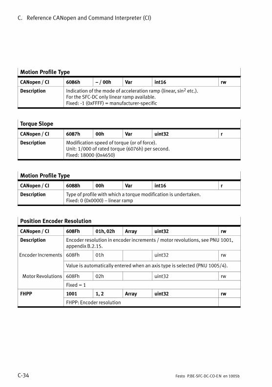
C. Reference CANopen and Command Interpreter (CI)
C−34 Festo P.BE−SFC−DC−CO−EN en 1005b
Motion Profile Type
CANopen / CI 6086h � / 00h Var int16 rw
Description Indication of the mode of acceleration ramp (linear, sin2 etc.).For the SFC−DC only linear ramp available.Fixed: −1 (0xFFFF) = manufacturer−specific
Torque Slope
CANopen / CI 6087h 00h Var uint32 r
Description Modification speed of torque (or of force).Unit: 1/000 of rated torque (6076h) per second.Fixed: 18000 (0x4650)
Motion Profile Type
CANopen / CI 6088h 00h Var int16 r
Description Type of profile with which a torque modification is undertaken.Fixed: 0 (0x0000) � linear ramp
Position Encoder Resolution
CANopen / CI 608Fh 01h, 02h Array uint32 rw
Description Encoder resolution in encoder increments / motor revolutions, see PNU 1001,appendix B.2.15.
Encoder Increments 608Fh 01h uint32 rw
Value is automatically entered when an axis type is selected (PNU 1005/4).
Motor Revolutions 608Fh 02h uint32 rw
Fixed = 1
FHPP 1001 1, 2 Array uint32 rw
FHPP: Encoder resolution

C. Reference CANopen and Command Interpreter (CI)
C−35Festo P.BE−SFC−DC−CO−EN en 1005b
Gear Ratio
CANopen / CI 6091h 01h, 02h Array uint32 rw
Description Ratio of motor revolutions to spindle revolutions (drive output revolutions)(Gear ratio = motor revolutions / spindle revolutions), see PNU 1002,appendix�B.2.15.
Motor Revolutions 6091h 01h uint32 rw
Gear ratio � numerator.
Shaft Revolutions 6091h 02h uint32 rw
Gear ratio � denominator.
FHPP 1002 1, 2 Array uint32 rw
Feed Constant
CANopen / CI 6092h 01h, 02h Array uint32 rw
Description Feed constant = feed / spindle revolutions, see PNU 1003, appendix B.2.15.
Feed 6092h 01h uint32 rw
Feed constant � numerator.Value is automatically entered when an axis type is selected (PNU 1005/4).
Shaft Revolutions 6092h 02h uint32 rw
Feed constant − denominator.
FHPP 1003 1, 2 Array uint32 rw
Position Factor
CANopen / CI 6093h 01h ... 02h Array uint32 rw
Description Conversion factor for number of encoder increments per 1 feed unit on thespindle, see PNU 1004, appendix B.2.15.
Numerator 6093h 01h uint32 rw
Position factor � numerator.Value is automatically entered when an axis type is selected (PNU 1005/4).
Denominator 6093h 02h uint32 rw
Position factor � denominator.
FHPP 1004 1, 2 Array uint32 rw

C. Reference CANopen and Command Interpreter (CI)
C−36 Festo P.BE−SFC−DC−CO−EN en 1005b
Homing Method
CANopen / CI 6098h � / 00h Var int8 rw
Description Defines the method by which the drive performs homing,see�PNU�1011,�appendix B.2.16.Changing the homing method influences object 607Ch.
FHPP 1011 � Var int8 rw
Homing Speeds
CANopen / CI 6099h 01h, 02h Array uint32 rw
Description Speeds during homing in inc/s, see PNU 1012, appendix B.2.16.
Search REF 6099h 01h uint32 rw
Speed when searching for the reference point REF
Search AZ 6099h 02h uint32 rw
Speed when moving to the axis zero point AZ
FHPP 1012 1, 2 Array uint32 rw
FHPP: Homing velocities

C. Reference CANopen and Command Interpreter (CI)
C−37Festo P.BE−SFC−DC−CO−EN en 1005b
Torque Control Parameters
CANopen / CI 60F6h 01h ... 05h uint32 rw
Description Force control parameters, see PNU 510 and 511, appendix B.2.10 as well asPNU 552 ... 554, appendix B.2.14.
Stroke Limit 60F6h 01h uint32 rw
Maximum permitted stroke with active force mode, see PNU 510.
Force Mode Speed 60F6h 02h uint32 rwpLimit Maximum permitted speed with active force mode, see PNU 554.
Force Targetd
60F6h 03h uint32 rwgWindow Target window of the force, see PNU 552.
Force Damping 60F6h 04h uint32 rwp gTime Damping time of the force, see PNU 553.
Min Torque/Force 60F6h 05h uint32 rwq /
The lowest permissible torque (force) of the motor, see PNU 511.
FHPP 510, 511,552 ... 554
� uint32, uint16, rw

C. Reference CANopen and Command Interpreter (CI)
C−38 Festo P.BE−SFC−DC−CO−EN en 1005b
Position Control Parameter Set
CANopen / CI 60FBh 12h ... 15h, 17h, 20h Array uint16 rw
Description Control parameters as well as parameters for �quasi−absolute positiondetection", see PNU 1024, appendix B.2.17.These parameters are for service purposes.
Gain Position 1024 12h uint16 rw
Gain position controller
Gain Velocity 1024 13h uint16 rwy
Gain velocity controller
I−Fraction Velocity 1024 14h uint16 rwy
I−part of speed controller.
Gain Current(current
1024 15h uint16 rw(current
amplification) Gain current controller
I−Fraction Current 1024 16h uint16 rw
I−part current controller.
Gain Velocity 1024 17h uint16 rwyTrajectory Gain speed controller � trajectory generator.
Save Position 1024 20h uint16 rw
Save current position on power−off.
FHPP 1024 18 ... 21, 23, 32 Array uint16 rw

C. Reference CANopen and Command Interpreter (CI)
C−39Festo P.BE−SFC−DC−CO−EN en 1005b
Local Digital Inputs
CANopen / CI 60FDh � / 00h Var uint32 r
Description Map of digital inputs, see PNU 303, appendix B.2.7.
FHPP 303 � Var uint32 ro
Local Digital Outputs
CANopen / CI 60FEh 01h, 02h Array uint32 rw
Description Map of digital outputs, see PNU 304, appendix B.2.7.
Digital Outputs 60FEh 01h uint32 rwg p
For SFC−DC−...−CO always 0 (writing not permitted).
Mask 60FEh 02h uint32 rw
For SFC−DC−...−CO always 0 (writing not permitted).
FHPP 304 1, 2 Array uint32 rw
Motor Type
CANopen / CI 6402h � / 00h Var uint16 rw
Description Classification of the motor, see PNU 1030, appendix B.2.18.
FHPP 1030 � Var uint16 rw
Motor Data
CANopen / CI 6410h 01h, 03h Record uint32 ro/rw
Description Motor−specific data, see PNU 1025, appendix B.2.17.
Serial number 6410h 01h uint32 ro
reserved (serial number of the motor)
Time Max. Current 6410h 03h uint32 rw
Permitted duration of the double motor rated current.
FHPP 1025 1, 3 Array uint32 ro/rw
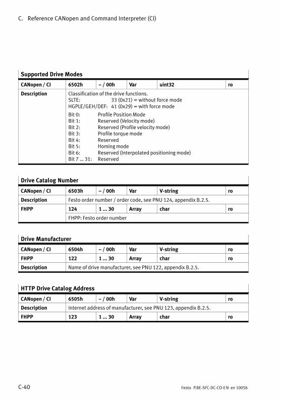
C. Reference CANopen and Command Interpreter (CI)
C−40 Festo P.BE−SFC−DC−CO−EN en 1005b
Supported Drive Modes
CANopen / CI 6502h � / 00h Var uint32 ro
Description Classification of the drive functions.SLTE: 33 (0x21) = without force modeHGPLE/GEH/DEF: 41 (0x29) = with force mode
Bit 0: Profile Position ModeBit 1: Reserved (Velocity mode)Bit 2: Reserved (Profile velocity mode)Bit 3: Profile torque modeBit 4: ReservedBit 5: Homing modeBit 6: Reserved (Interpolated positioning mode)Bit 7 � 31: Reserved
Drive Catalog Number
CANopen / CI 6503h � / 00h Var V−string ro
Description Festo order number / order code, see PNU 124, appendix B.2.5.
FHPP 124 1 ... 30 Array char ro
FHPP: Festo order number
Drive Manufacturer
CANopen / CI 6504h � / 00h Var V−string ro
FHPP 122 1 ... 30 Array char ro
Description Name of drive manufacturer, see PNU 122, appendix B.2.5.
HTTP Drive Catalog Address
CANopen / CI 6505h � / 00h Var V−string ro
Description Internet address of manufacturer, see PNU 123, appendix B.2.5.
FHPP 123 1 ... 30 Array char ro

C. Reference CANopen and Command Interpreter (CI)
C−41Festo P.BE−SFC−DC−CO−EN en 1005b
Drive Data
CANopen / CI 6510h 01h ... 08h,22h, 31h,32h, 40h ... 45h,A0h 1)
Record (Array)
int16, uint16, uint32(uint32)
ro/rw
Description General motor data, see PNU 1026, appendix B.2.17.
Output StageT
6510h 31h(01h), int16 (uint32) rop gTemp. Temperature of the end stage in °C.
Value range: −40 ... 85 (SI 01h: 0 ... 85)
Output StageM T
6510h 32h(02h), uint16 (uint32) rop gMax. Temp. Maximum temperature of the output stage in °C.
Motor RatedC t
6510h 40h(03h), uint32 (uint32) roCurrent Nominal motor current in mA
Value is automatically entered when an axis type is selected (PNU 1005/4).
Current Limit 6510h 41h(04h), uint16 (uint32) ro
Maximum motor current, identical to PNU 1034.
Lower Current Limit 6510h 42h(05h), in16 (uint32) ro
Lower current limit value in 1/1000 of the rated motor current
I/O Control 6510h 43h(06h), uint16 (uint32) rw/
Control of the control interface (see also object 207Dh).
Controller SerialN b
6510h A0h (07h) uint32 (uint32) roNumber Serial number of the controller in format 0xDDMYYSSS:
Following ErrorWi d
6510h 22h (08h) uint32 (uint32) rogWindow Message window for following error monitoring in increments.
Current calibrationl
6510h 44h uint16 rovalue Calibration value for current control.
Current actual value 6510h 45h int16 ro
Current actual value
FHPP 1026 1 ... 8 Array uint32 ro/rw1) Objects 6510/44h and 6510/45h not available via FHPP

C. Reference CANopen and Command Interpreter (CI)
C−42 Festo P.BE−SFC−DC−CO−EN en 1005b
C.2 Status machine as per DS 402
DS 402 status diagram
power disabled
Astart
switched off
Hfault reaction active
Bnot ready to switch on
Cswitch on disabled
Dready to switch on
Eswitched on
Foperation enable
fault
power enabled
Gquick stop active
1915
13
140
12
10
11
16
(1)
2 7
3
6
4 58
9
Ifault
20
Fig.�C/2: DS 402 status diagram

C. Reference CANopen and Command Interpreter (CI)
C−43Festo P.BE−SFC−DC−CO−EN en 1005b
Description of the statuses
Status Description
A �Start" This state is assumed at power−on, on reset or when a resetcommand is entered via the fieldbus. After execution of thestartup�code, power to the power section is cut and the statusbranches to�B.
B �Not ready to switch on" In this status logic self−tests are carried out. Internal workingvariables are initialised. The mechanical brake is actuated, if fitted.The power supply to the power section remains cut.The�fieldbus�interface is initialised and communication enabled.The�CI is initialised at the serial interface.
C �Switch on disabled" The supply to the power section remains cut. The fieldbus and/orCI�communication initialised in status B is started, enablingcontroller parameters, program records etc. to be modified.As from this status, changes of state are possible only by way offieldbus commands or if a serious error has occurred.
D �Ready to switch on" The final output stage is switched off; the motor is not energised.The drive can be moved freely. The self−test and monitoring functionsof the output stage are deactivated.By way of fieldbus and/or CI communication controller parameters,program records etc. can be modified (see also status E).
E �Switched on" The final output stage is switched on and the drive is stopped in acontrolled manner at the position crossed at during the transition toswitched−on. The self−test and monitoring functions of the outputstage are activated.
F �Operation enable" The drive waits for positioning tasks and executes them.Normal�operating status after successful initialisation.
G �Quick stop active" The Quick stop function has been activated. The drive runs asparameterised (ramp) and then stops. The power section and motorremain switched on, acceptance of positioning tasks is refused.

C. Reference CANopen and Command Interpreter (CI)
C−44 Festo P.BE−SFC−DC−CO−EN en 1005b
Status Description
H �Fault reaction active" This status can be assumed from any situation if a serious error isdetected. The parameterised error response (emergency ramp,immediate stop etc.) is executed. Communication via the fieldbus ismaintained, parameter modifications are permitted. The motorremains switched on.
I �Fault" In this status the motor remains switched on, provided the errorwhich has occurred permits. Otherwise the output stage is disabledand the mechanical brake is actuated. No more positioningmovements are executed.
Tab.�C/5: Description of the statuses
Description of the transfer conditions
Condition for statustransfer
Description
0 �Start" −> �Not ready to switch on"
This status transition always takes place unconditionally after a(re)start.
1 �Not ready to switch on" −> �Switch on disabled"
Note: Not applicable to the SFC−DC. Transition 20 is defined instead.The self−test of the 5V logic has been completed successfully.Communication via the fieldbus can, but does not have to be alreadyactive.No special signal levels from DS 402 are required for the change ofstatus.
2 �Switch on disabled" −> �Ready to switch on"
Fault reset = 0, Quick stop = 1, Enable voltage = 1, Switch on = 0.No serious error.
3 �Ready to switch on" −> �Switched on"
Fault reset = 0, Enable operation = 0, Quick stop = 1, Enable voltage = 1, Switch on = 1.Note: In DS402 the same status transition also forEnable�Operation�= 1, rest the same. This combination is alsoprovided for transitions 4 and 16 however, but in 4 there is a conflict.So this combination is not applied here.No serious error.
4 �Switched on" −> �Operation enable"
Fault reset = 0, Enable operation = 1, Quick stop = 1, Enable voltage = 1, Switch on = 1.No serious error.

C. Reference CANopen and Command Interpreter (CI)
C−45Festo P.BE−SFC−DC−CO−EN en 1005b
Condition for statustransfer
Description
5 �Ready to switch on" −> �Switched on"
Fault reset = 0, Enable operation = 0, Quick stop = 1, Enable voltage = 1, Switch on = 1.No serious error.
6 �Switched on" −> �Ready to switch on"
Fault reset = 0, Quick stop = 1, Enable voltage = 1, Switch on = 0.No serious error.
7 �Ready to switch on" −> �Switch on disabled"
Fault reset = 0, Enable voltage = 0 or Fault reset = 0, Quick stop = 0, Enable voltage = 1.No serious error.
8 �Operation enable" −> �Ready to switch on"
Fault reset = 0, Quick stop = 1, Enable voltage = 1, Switch on = 0.No serious error.
9 �Operation enable" −> �Switch on disabled"
Fault reset = 0, Enable voltage = 0.No serious error.
10 �Switched on" −> �Switch on disabled"
Fault reset = 0, Enable voltage = 0 or Fault reset = 0, Quick stop = 0, Enable voltage = 1.No serious error.
11 �Operation enable" −> �Quick stop active"
Fault reset = 0, Quick stop = 0, Enable voltage = 1.No serious error.
12 �Quick stop active" −> �Switch on disabled"
Fault reset = 0, Enable voltage = 0.No serious error.
13 From anywhere to �Fault reaction active"
Serious error, dependent on the device technology employed, whichforces normal operation to be aborted. The status transition isindependent of the control signals currently being sent.
14 �Fault reaction active" −> �Fault"
The cause of the fault must be eliminated (e.g. overheating,temperature reduced to permissible level). The emergency stopreaction is completed.A positive edge comes from the fieldbus on Fault Reset.
15 �Fault" −> �Switch on disabled"
Fault Reset = positive edge and at least one of the signalsEnable�Operation, Quick Stop, Enable Voltage and Switch on not 1.No serious error.
16 �Quick stop active" −> �Operation enable"
Fault reset = 0, Enable operation = 1, Quick stop = 1,Enable�voltage�= 1, Switch on = 1.No serious error.

C. Reference CANopen and Command Interpreter (CI)
C−46 Festo P.BE−SFC−DC−CO−EN en 1005b
Condition for statustransfer
Description
19 �Fault" −> �Switched on"
Fault reset = positive edge, Enable operation = 1, Quick stop = 1, Enable voltage = 1, Switch on = 1.Note: This transition is not included in the DS 402 profile.However,�it�is required for drives with non−self−locking shut−offcharacteristics, so as to avoid uncontrolled movement under loadwhen the drive is switched off.
20 �Not ready to switch on" −> �Ready to switch on"
Note: For SFC−DC replaces transitions 1 and 2.Fault reset = 0, Quick stop = 1, Enable voltage = 1, Switch on = 0.The self−test of the 5V logic has been completed successfully.Communication via the fieldbus can, but does not have to be alreadyactive.No serious error.
Tab.�C/6: Description of the transfer conditions

C. Reference CANopen and Command Interpreter (CI)
C−47Festo P.BE−SFC−DC−CO−EN en 1005b
C.3 Data transmission with the Command Interpreter
C.3.1 Procedure
CautionIn special application cases, access with CI commandsenables parametrisation and commissioning of the SFC−DCdirectly via the RS232 interface, though it is not suitablefor real−time capable communication, such as for control.Control of the SFC−DC via RS232 also requires:
� a risk estimation by the user
� ambient conditions free of interference,
� reliability of data transmission e.g. via the controlprogram of the host.
· Use preferably the control panel or the FCT forcommissioning and parametrisation.
· Note that control of the SFC−DC via the RS232 does notcomply with designated use.
WarningInjury to people and damage to property.
Full access to the internal variables of the controller ispossible via CI commands. Incorrect operation can causethe controller to react unexpectedly and the motor maystart in an uncontrolled manner.
· Use the CI commands only if you already haveexperience of Service Data Objects.
· Inform yourself about using the Objects in theCiA�Draft�Standard 402 before you use the CI commandsof the Command Interpreter of the SFC−DC.
For data transmission you will require acommercially−available terminal program or the CI terminal ofthe SFC−DC plug−in in the Festo Configuration Tool.

C. Reference CANopen and Command Interpreter (CI)
C−48 Festo P.BE−SFC−DC−CO−EN en 1005b
Carry out the following steps:
· Connect the SFC−DC to your PC via the RS232 interface.Observe here the instructions in chapter 3.5.
· If necessary, adapt the PC interface to the followingtransmission protocol.
Transmission protocol
Transmission speed (baud rate) 9600 Baud
Data format Asynchronous character frame:� 1 start bit� 8 data bits� No parity bit� 1 stop bit
Tab.�C/7: Specifications of the transmission protocol
· Initialise the data transmission with the followingcommand:
Command 310D h Response 31310D h
1 <CR> 11 <CR>
· Select the commands in accordance with the object list inappendix C.4.1, Tab.�C/13.
· Use CI commands only if you already know their effectsand if they are permitted for your SFC−DC.
· For the syntax of the commands, follow the information inappendix C.3.2.

C. Reference CANopen and Command Interpreter (CI)
C−49Festo P.BE−SFC−DC−CO−EN en 1005b
C.3.2 Composition of the CI commands
The contents of the commands implemented in theCommand�Interpreter of the SFC−DC are based on the objectsstandardised by CANopen (CiA Draft Standard 402):Group 1xxx Device descriptionGroup 2xxx Festo commandsGroup 6xxx Commands as per CANopen
The total of all parametrisation and control possibilities isreferred to as the object directory. Every object is assigned aunique number (Index, Subindex) used for accessing theobject.
CautionLoss of data.
The Command Interpreter (CI) contains commands whichreorganise or delete parts of the memory. Existing data isthereby destroyed:
· It is preferable to use the FCT or the control panel forcommissioning and parametrisation.
· Use the CI commands only in special cases which requiredirect access to the controller.
· Use CI commands only if you already know their effectsand if they are permitted for your SFC−DC.

C. Reference CANopen and Command Interpreter (CI)
C−50 Festo P.BE−SFC−DC−CO−EN en 1005b
Access procedure
The higher−order controller sends the controller either a writecommand (WRITE) to modify a parameter in the objectdirectory, or a read command (READ) to read out a parameter.
For each command the higher−order controller receives aresponse which either contains the value read or, in the caseof a write command, serves as an acknowledgement.The�transmitted value (1, 2 or 4 data bytes) depends on thedata type of the object to be read or written.
WRITE (W) Write commands (W) transfer a value in the specified formatto the SFC−DC. As a reply, Write commands will be reflectedexactly character by character from the SFC−DC controller.A�checksum <PS> is inserted in front of the <CR>.
READ (R) Read commands (R) transfer a value from the SFC−DC.The�reply from the SFC−DC controller contains thedownloaded value. A checksum <PS> is inserted in front ofthe�<CR>.
All commands are entered as a character sequence withoutany empty spaces. A hex character is a Char character inhex�format.
Acc 1) Command Response
WW 2)
=IIIISS:<value><CR>=IIIISS:<Value><PS><CR>
=IIIISS:<Value><PS><CR>
RR 2)
?IIIISS<CR>?IIIISS<PS><CR>
=IIIISS:<Value><PS><CR>
1) Access: W = write, R = read2) With activated checksum comparison at the SFC−DC,
see appendix C.3.3
Tab.�C/8: Syntax of a CI command/reply

C. Reference CANopen and Command Interpreter (CI)
C−51Festo P.BE−SFC−DC−CO−EN en 1005b
Syntax Explanation
�=", �?" Initial character for write or read commands
IIII Index in 4 hexadecimal digits
SS Subindex in 2 hexadecimal digitsIf the addressed object does not have an indexedparameter, subindex <00> is specified.
�:" Separator
<Value> Data in a format depending on data type
<PS> Check sum in 2 hexadecimal digits (see appendix C.3.3)
<CR> End character <Carriage Return> ($0D)
Tab.�C/9: Elements of syntax of a CI command/reply
Data type
The transmitted value (1, 2 or 4 data bytes as hex number)depends on the data type of the object to be read or written.The following data types are supported:
Type Hex Format
UINT8 2H 8 bits without sign: 0 � 255
INT8 8 bits with sign: −128 � 127
UINT16 4H 16 bits without sign: 0 � 65535
INT16 16 bits with sign: −32768 � 32767
UINT32 8H 32 bits without sign: 0 � (232 − 1)
INT32 32 bits without sign: −231 � +(231 − 1)
V−string Corresponds to the preset string
Tab.�C/10: Data types
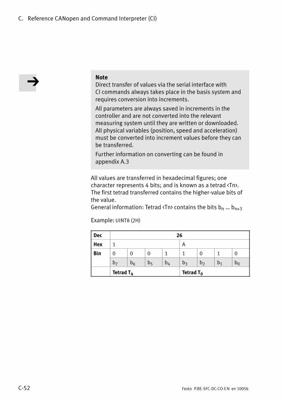
C. Reference CANopen and Command Interpreter (CI)
C−52 Festo P.BE−SFC−DC−CO−EN en 1005b
NoteDirect transfer of values via the serial interface withCI�commands always takes place in the basis system andrequires conversion into increments.
All parameters are always saved in increments in thecontroller and are not converted into the relevantmeasuring system until they are written or downloaded.All�physical variables (position, speed and acceleration)must be converted into increment values before they canbe transferred.
Further information on converting can be found inappendix A.3
All values are transferred in hexadecimal figures; onecharacter represents 4 bits; and is known as a tetrad <Tn>.The first tetrad transferred contains the higher−value bits ofthe value. General information: Tetrad <Tn> contains the bits bn � bn+3
Example: UINT8 (2H)
Dec 26
Hex 1 A
Bin 0 0 0 1 1 0 1 0
b7 b6 b5 b4 b3 b2 b1 b0
Tetrad T4 Tetrad T0

C. Reference CANopen and Command Interpreter (CI)
C−53Festo P.BE−SFC−DC−CO−EN en 1005b
C.3.3 Checking the data
Invalid values Transferred parameters and values are checked by theSFC−DC before being accepted. In the case of invalidparameters or values, an error message will not appear inthe response; rather, the transferred value will always bereturned.
NoteThe following applies when writing the objects:
� Discrete values (values from a value list):An invalid value will not be accepted, the previouslyvalid value will be retained.
� Continuous values (values from a continuous interval):An invalid value will be limited up to the next permittedminimum or maximum value.
RecommendationCheck that values and parameters have been written correctlyby downloading the current contents of the parameter orvalue with one of the following Read commands.
Transmission In the case of a transmission error between the higher−levelcontroller and the SFC−DC, instead of the usual response,the�value <0x00FF> will be transferred (see Object 2FF0).
Possible causes:
� incorrect initial character, separating character or emptycharacter
� incorrect hex digit
� incorrect value type.
Check sum <CS> The higher level controller must compare the sent commandwith the �Echo" from the SFC−DC and check the check sum.Additional check sum comparison at the SFC−DC for receivedcommands can be optionally activated (CI Object 20F3h).The�higher−level controller must then insert a check sumbefore the termination character (CR = Carriage return). If the SFC−DC detects a deviation in the check sum then,instead of the usual response, the value <0xFFFF> will betransferred (see Object 2FF0h).

C. Reference CANopen and Command Interpreter (CI)
C−54 Festo P.BE−SFC−DC−CO−EN en 1005b
The check sum is calculated based on the case(upper/lower�case) of the command; the check sum of theresponse is always based on upper case.
Check sum <PS> W/R Command Response
Default(CI object 20F300 00)
W =IIIISS:<value><CR> =IIIISS:<Value><PS><CR>(CI object 20F300:00)
R ?IIIISS<CR> =IIIISS:<Value><PS><CR>
Optional(CI object 20F300 01)
W =IIIISS:<Value><PS><CR> =IIIISS:<Value><PS><CR>(CI object 20F300:01)
R ?IIIISS><PS><CR> =IIIISS:<Value><PS><CR>
W = writeR = read
Tab.�C/11: Command/Response syntax (optionally with check sum comparison bythe�SFC−DC)
Check sum <PS>
Calculation Sum of all ASCII characters sent, reduced to 1 byte.W: <PS> = �=IIIISS:<Value>" modulo 256R: <PS> = �?IIIISS" modulo 256
ExampleCommand =IIIISS:<Value><CR>
=20F300:00ASCII−> = 2 0 F 3 0 0 : 0 0HEX 3D+32+30+46+33+30+30+3A+30+30Sum 212hMod 256 212h mod 100h = 12hResponse =20F300:0012
Format 2 Hexadecimal numbers, UINT8
Tab.�C/12: Check sum

C. Reference CANopen and Command Interpreter (CI)
C−55Festo P.BE−SFC−DC−CO−EN en 1005b
C.4 CI objects
C.4.1 Object overview (Index, Subindex)
The following overview shows all CI objects,where�appropriate with the corresponding FHPP parameternumbers.
NoteThe following table contains an overview of the CI objects.Some of the objects may be used only for certain productvariants or only with limitations (e.g. writing only forservice purposes). Note the detailed descriptions of theobject.
You will find the descriptions of the CI objects in the followingsections (see �See" column):
� Descriptions of the CI objects with the correspondingPNUs as per FHPP in appendix B.2.4 to B.2.19
� Descriptions of the additional CI objects beginning atappendix�C.1.2.
Name CI FHPP See
Object SI PNU
Group 1xxx
Device Type 1000h 00h � C.1.2
Manufacturer Device Name 1008h 00h 120 B.2.5
Manufacturer Hardware Version 1009h 00h � C.1.2
Manufacturer Software Version 100Ah 00h � C.1.2

C. Reference CANopen and Command Interpreter (CI)
C−56 Festo P.BE−SFC−DC−CO−EN en 1005b
Name SeeFHPPCIName See
PNUSIObject
Group 2xxx
Record Number 2032h 01h � C.1.3
Record Number 2033h 00h 400 B.2.8
Standstill Position Window 2040h 00h 1042 B.2.19
Standstill Window Time 2041h 00h 1043 B.2.19
Version FHPP 2066h 00h 102 B.2.4
Version FCT PlugIn Min 2067h 00h � C.4.3
Version FCT PlugIn Opt 2068h 00h � C.4.3
Manufacturer Hardware Version 2069h 00h 100 B.2.4
Manufacturer Firmware Version 206Ah 00h 101 B.2.4
Controller Serial Number 2072h 00h 114 B.2.4
Device Control 207Dh 00h 125 B.2.5
Diagnostic Event 20C8h 01h � 10h 200 B.2.6
Error Number 20C9h 01h � 10h 201 B.2.6
Time Stamp 20CAh 01h � 10h 202 B.2.6
Diagnosis Memory Parameter 20CCh 01h � 04h 204 B.2.6
Scaling 20D0h 01h, 02h � C.1.3
Record Table Element 20E0h 01h � 05h � C.1.3
Axis Parameter 20E2h 01h � 05h 1005 B.2.15
Controller Type 20E3h 00h � C.4.3
Jog Mode Time Phase 1 20E9h 00h / 21h 534 B.2.12
Record Control Byte 1 20EAh 01h � 20h 401 B.2.8
Record Target Position 20ECh 01h � 20h 404 B.2.8
... Velocity 20EDh 01h � 20h 406 B.2.8y
21h 531 B.2.12
... Acceleration 20EEh 01h � 20h 407 B.2.8
21h 532 B.2.12
22h 541 B.2.13
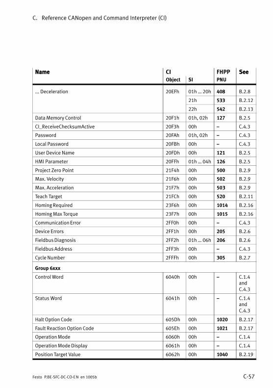
C. Reference CANopen and Command Interpreter (CI)
C−57Festo P.BE−SFC−DC−CO−EN en 1005b
Name SeeFHPPCIName See
PNUSIObject
... Deceleration 20EFh 01h � 20h 408 B.2.8
21h 533 B.2.12
22h 542 B.2.13
Data Memory Control 20F1h 01h, 02h 127 B.2.5
CI_ReceiveChecksumActive 20F3h 00h � C.4.3
Password 20FAh 01h, 02h � C.4.3
Local Password 20FBh 00h � C.4.3
User Device Name 20FDh 00h 121 B.2.5
HMI Parameter 20FFh 01h � 04h 126 B.2.5
Project Zero Point 21F4h 00h 500 B.2.9
Max. Velocity 21F6h 00h 502 B.2.9
Max. Acceleration 21F7h 00h 503 B.2.9
Teach Target 21FCh 00h 520 B.2.11
Homing Required 23F6h 00h 1014 B.2.16
Homing Max Torque 23F7h 00h 1015 B.2.16
Communication Error 2FF0h 00h � C.4.3
Device Errors 2FF1h 00h 205 B.2.6
Fieldbus Diagnosis 2FF2h 01h � 06h 206 B.2.6
Fieldbus Address 2FF3h 00h � C.4.3
Cycle Number 2FFFh 00h 305 B.2.7
Group 6xxx
Control Word 6040h 00h � C.1.4andC.4.3
Status Word 6041h 00h � C.1.4andC.4.3
Halt Option Code 605Dh 00h 1020 B.2.17
Fault Reaction Option Code 605Eh 00h 1021 B.2.17
Operation Mode 6060h 00h � C.1.4
Operation Mode Display 6061h 00h � C.1.4
Position Target Value 6062h 00h 1040 B.2.19
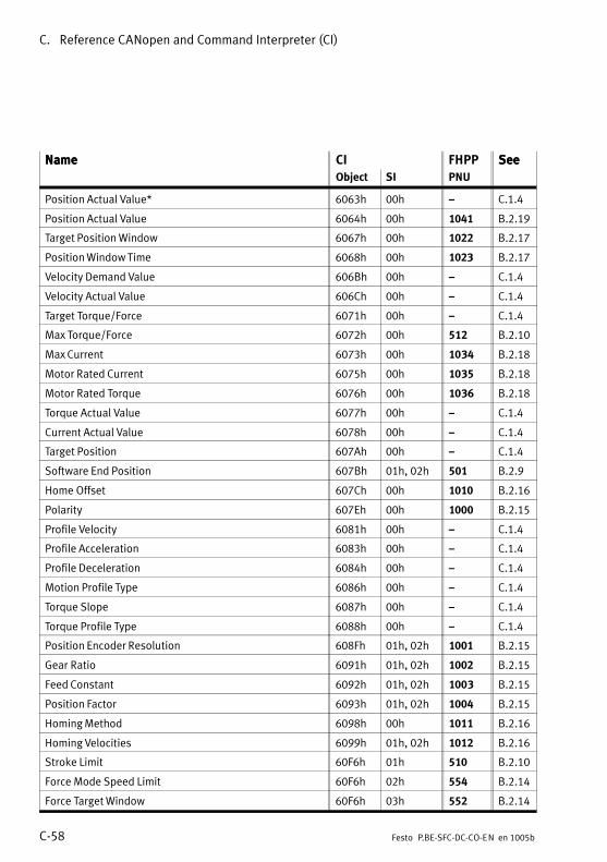
C. Reference CANopen and Command Interpreter (CI)
C−58 Festo P.BE−SFC−DC−CO−EN en 1005b
Name SeeFHPPCIName See
PNUSIObject
Position Actual Value* 6063h 00h � C.1.4
Position Actual Value 6064h 00h 1041 B.2.19
Target Position Window 6067h 00h 1022 B.2.17
Position Window Time 6068h 00h 1023 B.2.17
Velocity Demand Value 606Bh 00h � C.1.4
Velocity Actual Value 606Ch 00h � C.1.4
Target Torque/Force 6071h 00h � C.1.4
Max Torque/Force 6072h 00h 512 B.2.10
Max Current 6073h 00h 1034 B.2.18
Motor Rated Current 6075h 00h 1035 B.2.18
Motor Rated Torque 6076h 00h 1036 B.2.18
Torque Actual Value 6077h 00h � C.1.4
Current Actual Value 6078h 00h � C.1.4
Target Position 607Ah 00h � C.1.4
Software End Position 607Bh 01h, 02h 501 B.2.9
Home Offset 607Ch 00h 1010 B.2.16
Polarity 607Eh 00h 1000 B.2.15
Profile Velocity 6081h 00h � C.1.4
Profile Acceleration 6083h 00h � C.1.4
Profile Deceleration 6084h 00h � C.1.4
Motion Profile Type 6086h 00h � C.1.4
Torque Slope 6087h 00h � C.1.4
Torque Profile Type 6088h 00h � C.1.4
Position Encoder Resolution 608Fh 01h, 02h 1001 B.2.15
Gear Ratio 6091h 01h, 02h 1002 B.2.15
Feed Constant 6092h 01h, 02h 1003 B.2.15
Position Factor 6093h 01h, 02h 1004 B.2.15
Homing Method 6098h 00h 1011 B.2.16
Homing Velocities 6099h 01h, 02h 1012 B.2.16
Stroke Limit 60F6h 01h 510 B.2.10
Force Mode Speed Limit 60F6h 02h 554 B.2.14
Force Target Window 60F6h 03h 552 B.2.14
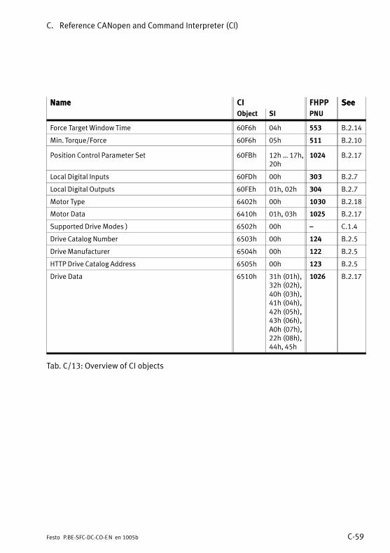
C. Reference CANopen and Command Interpreter (CI)
C−59Festo P.BE−SFC−DC−CO−EN en 1005b
Name SeeFHPPCIName See
PNUSIObject
Force Target Window Time 60F6h 04h 553 B.2.14
Min. Torque/Force 60F6h 05h 511 B.2.10
Position Control Parameter Set 60FBh 12h � 17h,20h
1024 B.2.17
Local Digital Inputs 60FDh 00h 303 B.2.7
Local Digital Outputs 60FEh 01h, 02h 304 B.2.7
Motor Type 6402h 00h 1030 B.2.18
Motor Data 6410h 01h, 03h 1025 B.2.17
Supported Drive Modes ) 6502h 00h � C.1.4
Drive Catalog Number 6503h 00h 124 B.2.5
Drive Manufacturer 6504h 00h 122 B.2.5
HTTP Drive Catalog Address 6505h 00h 123 B.2.5
Drive Data 6510h 31h (01h),32h (02h),40h (03h),41h (04h),42h (05h),43h (06h),A0h (07h),22h (08h),44h, 45h
1026 B.2.17
Tab.�C/13: Overview of CI objects

C. Reference CANopen and Command Interpreter (CI)
C−60 Festo P.BE−SFC−DC−CO−EN en 1005b
C.4.2 Representation of the parameter entries
Encoder Resolution
CI 608Fh 01h ... 02h Array uint32 rw2
Description Encoder resolution in increments / revolutionsThe encoder resolution is fixed and cannot be modified by the user.The�calculated value is derived from the fraction(encoder�increments/motor revolution).
Encoder Increments 608Fh 1 uint32 rw2
Range of values: 0 ... 232 − 1Default: 500
Motor Revolutions 608Fh 2 uint32 rw2
Fixed = 1
1 Name of the parameter in English
2 Object number
3 Subindices of parameter, if present (�: no subindex, simple variable)
4 Element class
5 Element variable type.
6 Read/Write permission: ro = read onlywo= write onlyrw = read and write
7 Description of the parameter
8 Name and description of subindices, if present
Fig.�C/1: Representation of the parameter entries
1 2 3 4 5 6
7
8

C. Reference CANopen and Command Interpreter (CI)
C−61Festo P.BE−SFC−DC−CO−EN en 1005b
C.4.3 Additional CI objects
Version FCT PlugIn Min
CI 2067h � / 00h Var V−string r
Description Minimum version of FCT SFC−DC plug−in required for commissioning the SFC−DCwith the firmware version being used.Format = �xx.yy" (xx = main version, yy = secondary version)
Version FCT PlugIn Opt.
CI 2068h � / 00h Var V−string r
Description Version of FCT SFC−DC plug−in optimally suited for commissioning of the SFC−DCwith the firmware version being used.Format = �xx.yy" (xx = main version, yy = secondary version)
Controller Type
CI 20E3h � Var uint8 r
Description Type of controller.Values:0 (0x00): Controller with display/keyboard (type ...−H2−...)1 (0x01): Controller without display/keyboard (type ...−H0−...)3 � 15: Cannot be set (reserved for future extensions)
CI_ReceiveChecksumActive
CI 20F3h � / 00h Var uint8 rw
Description Enable checksum checking of received CI telegrams, see�appendix C.3.3,Tab.�C/12.Values:0 (0x00): Disabled (default)1 (0x01): EnabledExample: Deactivate checksum: �=20F300:0012" (12 = checksum)

C. Reference CANopen and Command Interpreter (CI)
C−62 Festo P.BE−SFC−DC−CO−EN en 1005b
Password
CI 20FAh 01h, 02h Array V−string rw/ro
Description Managing the FCT password, entering the super password.
FCT password 20FAh 01h V−string rwp Password for the FCT softwareValue: <........> (fixed 8 characters, ASCII, 7−bit)Default: <00000000> (status upon delivery and after reset)
Super Password 20FAh 02h V−string rop Entering the super password.Resets all passwords (FCT password and HMI password, object 20FB).Contact�Festo Service if you require the super password.
Local Password
CI 20FBh � / 00h Var V−string rw
Description Managing the (local) HMI password to enable certain functions executed viathe control panel.Value: <........> (fixed 8 characters, ASCII, 7−bit)
Only the first 3 characters are evaluated.Default: <00000000> (status upon delivery and after reset)
Communication Error
CI 2FF0h � / 00h Var uint16 ro
Description Special object; see appendix C.3.3.In the case of a transmission error, the value <0xFF> will be transferred insteadof the usual response.
Fieldbus Address
CI 2FF3h � / 00h Var uint8 rw
Description Station address (MAC ID).Range of values: 1 � 127 (0x01 � 0x7F)The setting is saved remanently in the device. Switchover during runtime is notpossible. Changes that are made only become effective after the next poweron.Default: 0 (0x00) � invalid address

C. Reference CANopen and Command Interpreter (CI)
C−63Festo P.BE−SFC−DC−CO−EN en 1005b
Control Word DS 402
CI 6040h � / 00h Var uint16 rw
Description Modify the current controller status or trigger an activity.As changes of state take a certain amount of time, state changes triggered viathe control word must be read back via the status word. Only when therequested status can be read in the status word may a further command bewritten via the control word. For a description of the finite state machinesee�chapter 5.7.Values see Tab.�C/3.
Specific features when accessing via CI:� Reset Fault (Bit 7) as per DS 402 processing with positive edge,
but�via�CI�level evaluated.� Start bit (Bit 4) when Homing and positioning according to DS 402,
edge�triggered for CI but level evaluated. 0−set interpreted as stop.� HMI access locked (bit 14) only accessible via field bus.� Switch to �Operation enable" may simultaneously contain action−triggering
bits (Start, Jog, ...).� Shortened status transitions:
� Operation disable or Switch on command (same coding): State OPERATION ENABLE −> READY TO SWITCH ON.State READY TO SWITCH ON −> SWITCHED ON.
� Disable voltage command (bit 1 = 0, rest irrelevant) � all states −> READY TO SWITCH ON.
� Operation enable command (all states) −> OPERATION ENABLE.� Voltage disable and Quick stop commands −> READY TO SWITCH ON.
Status Word
CI 6041h � / 00h Var uint16 ro
Description Reading the current controller or regulator status. For a description of the finite state machine see chapter 5.7.Values see Tab.�C/4.
Specific features when accessing via CI:� Bit 4 in CI reversed polarity relative to DS 402.� In the Fault state, when power is applied to the axis, the state is
indicated not as xxx8, but xxxA, meaning �Switched on" is set.

C. Reference CANopen and Command Interpreter (CI)
C−64 Festo P.BE−SFC−DC−CO−EN en 1005b

Index
D−1Festo P.BE−SFC−DC−CO−EN en 1005b
Appendix D

D. Index
D−2 Festo P.BE−SFC−DC−CO−EN en 1005b
D. Index D−1 . . . . . . . . . . . . . . . . . . . . . . . . . . . . . . . . . . . . . . . . . . . . . . . . . . . . . . . . .

D. Index
D−3Festo P.BE−SFC−DC−CO−EN en 1005b
A
Absolute 5−19, B−29. . . . . . . . . . . . . . . . . . . . . . . . . . . . . . . . . .
Access procedure C−50. . . . . . . . . . . . . . . . . . . . . . . . . . . . . . .
AdapterM12 3−24. . . . . . . . . . . . . . . . . . . . . . . . . . . . . . . . . . . . . . . . Screw terminals 3−25. . . . . . . . . . . . . . . . . . . . . . . . . . . . . .
Axis parameter 4−10. . . . . . . . . . . . . . . . . . . . . . . . . . . . . . . . . Setting 4−20, 5−16. . . . . . . . . . . . . . . . . . . . . . . . . . . . . . . . . .
Axis type, Setting 4−17, 5−10. . . . . . . . . . . . . . . . . . . . . . . . . . .
Axis zero point XVI, 1−14, 5−16, B−50, C−32. . . . . . . . . . . . . . .
B
Basic modules 1−13. . . . . . . . . . . . . . . . . . . . . . . . . . . . . . . . .
BCD XIX. . . . . . . . . . . . . . . . . . . . . . . . . . . . . . . . . . . . . . . . . . .
Bus terminal 3−27. . . . . . . . . . . . . . . . . . . . . . . . . . . . . . . . . . .
C
Cable, Fieldbus 3−18. . . . . . . . . . . . . . . . . . . . . . . . . . . . . . . . .
Cables 3−5. . . . . . . . . . . . . . . . . . . . . . . . . . . . . . . . . . . . . . . . . .
CAN baud rate 5−23. . . . . . . . . . . . . . . . . . . . . . . . . . . . . . . . .
CAN node ID 5−22. . . . . . . . . . . . . . . . . . . . . . . . . . . . . . . . . . .
CAN parameters, Setting 4−26, 5−22. . . . . . . . . . . . . . . . . . . . .
CAN profile 5−24. . . . . . . . . . . . . . . . . . . . . . . . . . . . . . . . . . . .
CAN voltage supply 5−25. . . . . . . . . . . . . . . . . . . . . . . . . . . . .
CAN−BUS diagnosis 4−12. . . . . . . . . . . . . . . . . . . . . . . . . . . . .
CANopenDiagnosis via parameter channel 6−16. . . . . . . . . . . . . . . . Diagnostics 6−14. . . . . . . . . . . . . . . . . . . . . . . . . . . . . . . . . . General information 5−30. . . . . . . . . . . . . . . . . . . . . . . . . . .
CANopen interface 3−4. . . . . . . . . . . . . . . . . . . . . . . . . . . . . . .
CCON 5−43. . . . . . . . . . . . . . . . . . . . . . . . . . . . . . . . . . . . . . . . .
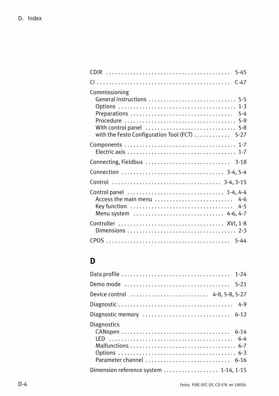
D. Index
D−4 Festo P.BE−SFC−DC−CO−EN en 1005b
CDIR 5−45. . . . . . . . . . . . . . . . . . . . . . . . . . . . . . . . . . . . . . . . .
CI C−47. . . . . . . . . . . . . . . . . . . . . . . . . . . . . . . . . . . . . . . . . . . .
CommissioningGeneral instructions 5−5. . . . . . . . . . . . . . . . . . . . . . . . . . . . . Options 1−3. . . . . . . . . . . . . . . . . . . . . . . . . . . . . . . . . . . . . . . Preparations 5−4. . . . . . . . . . . . . . . . . . . . . . . . . . . . . . . . . . Procedure 5−9. . . . . . . . . . . . . . . . . . . . . . . . . . . . . . . . . . . . . With control panel 5−8. . . . . . . . . . . . . . . . . . . . . . . . . . . . . . with the Festo Configuration Tool (FCT) 5−27. . . . . . . . . . . .
Components 1−7. . . . . . . . . . . . . . . . . . . . . . . . . . . . . . . . . . . . . Electric axis 1−7. . . . . . . . . . . . . . . . . . . . . . . . . . . . . . . . . . . .
Connecting, Fieldbus 3−18. . . . . . . . . . . . . . . . . . . . . . . . . . . .
Connection 3−4, 5−4. . . . . . . . . . . . . . . . . . . . . . . . . . . . . . . . . .
Control 3−4, 3−15. . . . . . . . . . . . . . . . . . . . . . . . . . . . . . . . . . . .
Control panel 1−4, 4−4. . . . . . . . . . . . . . . . . . . . . . . . . . . . . . . . Access the main menu 4−6. . . . . . . . . . . . . . . . . . . . . . . . . . Key function 4−5. . . . . . . . . . . . . . . . . . . . . . . . . . . . . . . . . . Menu system 4−6, 4−7. . . . . . . . . . . . . . . . . . . . . . . . . . . . . .
Controller XVI, 1−8. . . . . . . . . . . . . . . . . . . . . . . . . . . . . . . . . . . Dimensions 2−3. . . . . . . . . . . . . . . . . . . . . . . . . . . . . . . . . . . .
CPOS 5−44. . . . . . . . . . . . . . . . . . . . . . . . . . . . . . . . . . . . . . . . .
D
Data profile 1−24. . . . . . . . . . . . . . . . . . . . . . . . . . . . . . . . . . . .
Demo mode 5−21. . . . . . . . . . . . . . . . . . . . . . . . . . . . . . . . . . .
Device control 4−8, 5−8, 5−27. . . . . . . . . . . . . . . . . . . . . . . . . .
Diagnostic 4−9. . . . . . . . . . . . . . . . . . . . . . . . . . . . . . . . . . . . . .
Diagnostic memory 6−12. . . . . . . . . . . . . . . . . . . . . . . . . . . . .
DiagnosticsCANopen 6−14. . . . . . . . . . . . . . . . . . . . . . . . . . . . . . . . . . . . LED 6−4. . . . . . . . . . . . . . . . . . . . . . . . . . . . . . . . . . . . . . . . . Malfunctions 6−7. . . . . . . . . . . . . . . . . . . . . . . . . . . . . . . . . . . Options 6−3. . . . . . . . . . . . . . . . . . . . . . . . . . . . . . . . . . . . . . . Parameter channel 6−16. . . . . . . . . . . . . . . . . . . . . . . . . . . .
Dimension reference system 1−14, 1−15. . . . . . . . . . . . . . . . . .

D. Index
D−5Festo P.BE−SFC−DC−CO−EN en 1005b
Dimensions 2−3. . . . . . . . . . . . . . . . . . . . . . . . . . . . . . . . . . . . . .
Direct mode 1−5, 1−25, 5−38, 5−42, 5−73. . . . . . . . . . . . . . . . . .
Drive XVI, 1−8. . . . . . . . . . . . . . . . . . . . . . . . . . . . . . . . . . . . . . .
DS 402 1−24. . . . . . . . . . . . . . . . . . . . . . . . . . . . . . . . . . . . . . .
E
Earth terminal 3−9. . . . . . . . . . . . . . . . . . . . . . . . . . . . . . . . . . . .
Earthing 3−9. . . . . . . . . . . . . . . . . . . . . . . . . . . . . . . . . . . . . . . .
EDS file XIX, 5−32. . . . . . . . . . . . . . . . . . . . . . . . . . . . . . . . . . . .
Effective stroke 1−15. . . . . . . . . . . . . . . . . . . . . . . . . . . . . . . . .
Electric axis XVI. . . . . . . . . . . . . . . . . . . . . . . . . . . . . . . . . . . . .
EMC XVI. . . . . . . . . . . . . . . . . . . . . . . . . . . . . . . . . . . . . . . . . . .
Encoder XVI, 1−9. . . . . . . . . . . . . . . . . . . . . . . . . . . . . . . . . . . . .
Error numbers B−6. . . . . . . . . . . . . . . . . . . . . . . . . . . . . . . . . .
ESD 3−5. . . . . . . . . . . . . . . . . . . . . . . . . . . . . . . . . . . . . . . . . . . .
F
Fault numbers 6−13. . . . . . . . . . . . . . . . . . . . . . . . . . . . . . . . .
Festo Configuration Tool (FCT) XVI, 1−4. . . . . . . . . . . . . . . . . . . Installing 5−26. . . . . . . . . . . . . . . . . . . . . . . . . . . . . . . . . . . . Starting 5−27. . . . . . . . . . . . . . . . . . . . . . . . . . . . . . . . . . . . .
Festo Parameter Channel (FPC) XVI, B−3. . . . . . . . . . . . . . . . . .
FHPP 1−24, 5−37. . . . . . . . . . . . . . . . . . . . . . . . . . . . . . . . . . . . . Parameter groups B−12. . . . . . . . . . . . . . . . . . . . . . . . . . . . Parameter number (PNU) B−13. . . . . . . . . . . . . . . . . . . . . .
FHPP standard 5−39. . . . . . . . . . . . . . . . . . . . . . . . . . . . . . . . .
Field bus length 3−19. . . . . . . . . . . . . . . . . . . . . . . . . . . . . . . .
Fieldbus baud rate 3−19. . . . . . . . . . . . . . . . . . . . . . . . . . . . . .
Fieldbus cable 1−8, 3−18. . . . . . . . . . . . . . . . . . . . . . . . . . . . . .
Fieldbus plug 1−8, 3−22. . . . . . . . . . . . . . . . . . . . . . . . . . . . . . .
Force mode 5−38, 5−59, 5−75. . . . . . . . . . . . . . . . . . . . . . . . . . .
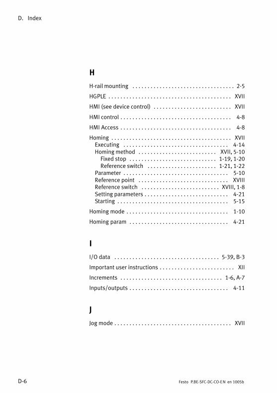
D. Index
D−6 Festo P.BE−SFC−DC−CO−EN en 1005b
H
H−rail mounting 2−5. . . . . . . . . . . . . . . . . . . . . . . . . . . . . . . . . .
HGPLE XVII. . . . . . . . . . . . . . . . . . . . . . . . . . . . . . . . . . . . . . . . .
HMI (see device control) XVII. . . . . . . . . . . . . . . . . . . . . . . . . .
HMI control 4−8. . . . . . . . . . . . . . . . . . . . . . . . . . . . . . . . . . . . .
HMI Access 4−8. . . . . . . . . . . . . . . . . . . . . . . . . . . . . . . . . . . . .
Homing XVII. . . . . . . . . . . . . . . . . . . . . . . . . . . . . . . . . . . . . . . . Executing 4−14. . . . . . . . . . . . . . . . . . . . . . . . . . . . . . . . . . . Homing method XVII, 5−10. . . . . . . . . . . . . . . . . . . . . . . . . . Fixed stop 1−19, 1−20. . . . . . . . . . . . . . . . . . . . . . . . . . . . . Reference switch 1−21, 1−22. . . . . . . . . . . . . . . . . . . . . . .
Parameter 5−10. . . . . . . . . . . . . . . . . . . . . . . . . . . . . . . . . . . Reference point XVIII. . . . . . . . . . . . . . . . . . . . . . . . . . . . . . Reference switch XVIII, 1−8. . . . . . . . . . . . . . . . . . . . . . . . . . Setting parameters 4−21. . . . . . . . . . . . . . . . . . . . . . . . . . . . Starting 5−15. . . . . . . . . . . . . . . . . . . . . . . . . . . . . . . . . . . . .
Homing mode 1−10. . . . . . . . . . . . . . . . . . . . . . . . . . . . . . . . . .
Homing param 4−21. . . . . . . . . . . . . . . . . . . . . . . . . . . . . . . . .
I
I/O data 5−39, B−3. . . . . . . . . . . . . . . . . . . . . . . . . . . . . . . . . . .
Important user instructions XII. . . . . . . . . . . . . . . . . . . . . . . . .
Increments 1−6, A−7. . . . . . . . . . . . . . . . . . . . . . . . . . . . . . . . . .
Inputs/outputs 4−11. . . . . . . . . . . . . . . . . . . . . . . . . . . . . . . . .
J
Jog mode XVII. . . . . . . . . . . . . . . . . . . . . . . . . . . . . . . . . . . . . . .

D. Index
D−7Festo P.BE−SFC−DC−CO−EN en 1005b
K
Key functionMenu selection 4−6. . . . . . . . . . . . . . . . . . . . . . . . . . . . . . . . Overview 4−5. . . . . . . . . . . . . . . . . . . . . . . . . . . . . . . . . . . . .
L
LED 6−4. . . . . . . . . . . . . . . . . . . . . . . . . . . . . . . . . . . . . . . . . . .
LineMotor 1−8. . . . . . . . . . . . . . . . . . . . . . . . . . . . . . . . . . . . . . . . . Power supply 1−8. . . . . . . . . . . . . . . . . . . . . . . . . . . . . . . . . . Programming 1−8. . . . . . . . . . . . . . . . . . . . . . . . . . . . . . . . . .
LSB XIX. . . . . . . . . . . . . . . . . . . . . . . . . . . . . . . . . . . . . . . . . . .
M
M12 adapter 3−24. . . . . . . . . . . . . . . . . . . . . . . . . . . . . . . . . . .
Menu system 4−6, 4−7. . . . . . . . . . . . . . . . . . . . . . . . . . . . . . . .
Motor 1−8. . . . . . . . . . . . . . . . . . . . . . . . . . . . . . . . . . . . . . . . . .
Motor cable 1−8. . . . . . . . . . . . . . . . . . . . . . . . . . . . . . . . . . . . .
Motor connection 3−4. . . . . . . . . . . . . . . . . . . . . . . . . . . . . . . .
Mounting 2−6. . . . . . . . . . . . . . . . . . . . . . . . . . . . . . . . . . . . . . . H−rail mounting 2−5. . . . . . . . . . . . . . . . . . . . . . . . . . . . . . . . . Wall mounting 2−4. . . . . . . . . . . . . . . . . . . . . . . . . . . . . . . . .
MSB XIX. . . . . . . . . . . . . . . . . . . . . . . . . . . . . . . . . . . . . . . . . .
N
Nominal stroke 1−15. . . . . . . . . . . . . . . . . . . . . . . . . . . . . . . . .
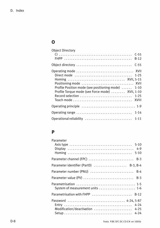
D. Index
D−8 Festo P.BE−SFC−DC−CO−EN en 1005b
O
Object DirectoryCI C−55. . . . . . . . . . . . . . . . . . . . . . . . . . . . . . . . . . . . . . . . . . FHPP B−12. . . . . . . . . . . . . . . . . . . . . . . . . . . . . . . . . . . . . . .
Object directory C−55. . . . . . . . . . . . . . . . . . . . . . . . . . . . . . . .
Operating mode XVII. . . . . . . . . . . . . . . . . . . . . . . . . . . . . . . . . Direct mode 1−25. . . . . . . . . . . . . . . . . . . . . . . . . . . . . . . . . Homing XVII, 5−15. . . . . . . . . . . . . . . . . . . . . . . . . . . . . . . . . Positioning mode XVII. . . . . . . . . . . . . . . . . . . . . . . . . . . . . . Profile Position mode (see positioning mode) 1−10. . . . . . Profile Torque mode (see Force mode) XVII, 1−10. . . . . . . . Record selection 1−25. . . . . . . . . . . . . . . . . . . . . . . . . . . . . . Teach mode XVIII. . . . . . . . . . . . . . . . . . . . . . . . . . . . . . . . . .
Operating principle 1−9. . . . . . . . . . . . . . . . . . . . . . . . . . . . . . .
Operating range 1−14. . . . . . . . . . . . . . . . . . . . . . . . . . . . . . . .
Operational reliability 1−11. . . . . . . . . . . . . . . . . . . . . . . . . . .
P
ParameterAxis type 5−10. . . . . . . . . . . . . . . . . . . . . . . . . . . . . . . . . . . . Display 4−9. . . . . . . . . . . . . . . . . . . . . . . . . . . . . . . . . . . . . . Homing 5−10. . . . . . . . . . . . . . . . . . . . . . . . . . . . . . . . . . . . .
Parameter channel (FPC) B−3. . . . . . . . . . . . . . . . . . . . . . . . . .
Parameter identifier (ParID) B−3, B−4. . . . . . . . . . . . . . . . . . .
Parameter number (PNU) B−4. . . . . . . . . . . . . . . . . . . . . . . . .
Parameter value (PV) B−3. . . . . . . . . . . . . . . . . . . . . . . . . . . . .
Parametrisation 1−5. . . . . . . . . . . . . . . . . . . . . . . . . . . . . . . . . . System of measurement units 1−6. . . . . . . . . . . . . . . . . . . . .
Parametrisation with FHPP B−12. . . . . . . . . . . . . . . . . . . . . . .
Password 4−24, 5−87. . . . . . . . . . . . . . . . . . . . . . . . . . . . . . . . . Entry 4−24. . . . . . . . . . . . . . . . . . . . . . . . . . . . . . . . . . . . . . . Modification/deactivation 4−25. . . . . . . . . . . . . . . . . . . . . . Setup 4−24. . . . . . . . . . . . . . . . . . . . . . . . . . . . . . . . . . . . . . .
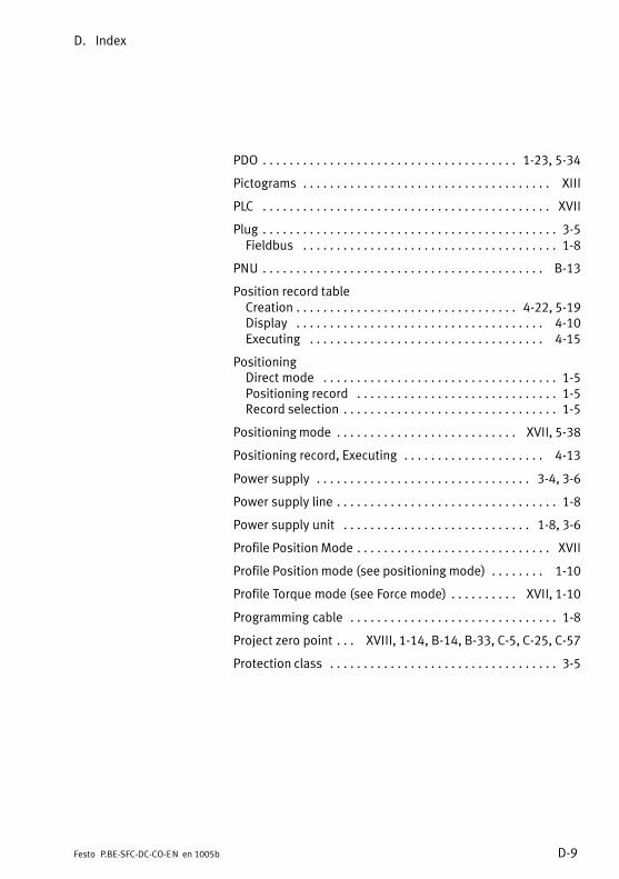
D. Index
D−9Festo P.BE−SFC−DC−CO−EN en 1005b
PDO 1−23, 5−34. . . . . . . . . . . . . . . . . . . . . . . . . . . . . . . . . . . . . .
Pictograms XIII. . . . . . . . . . . . . . . . . . . . . . . . . . . . . . . . . . . . .
PLC XVII. . . . . . . . . . . . . . . . . . . . . . . . . . . . . . . . . . . . . . . . . . .
Plug 3−5. . . . . . . . . . . . . . . . . . . . . . . . . . . . . . . . . . . . . . . . . . . . Fieldbus 1−8. . . . . . . . . . . . . . . . . . . . . . . . . . . . . . . . . . . . . .
PNU B−13. . . . . . . . . . . . . . . . . . . . . . . . . . . . . . . . . . . . . . . . . .
Position record tableCreation 4−22, 5−19. . . . . . . . . . . . . . . . . . . . . . . . . . . . . . . . . Display 4−10. . . . . . . . . . . . . . . . . . . . . . . . . . . . . . . . . . . . . Executing 4−15. . . . . . . . . . . . . . . . . . . . . . . . . . . . . . . . . . .
PositioningDirect mode 1−5. . . . . . . . . . . . . . . . . . . . . . . . . . . . . . . . . . . Positioning record 1−5. . . . . . . . . . . . . . . . . . . . . . . . . . . . . . Record selection 1−5. . . . . . . . . . . . . . . . . . . . . . . . . . . . . . . .
Positioning mode XVII, 5−38. . . . . . . . . . . . . . . . . . . . . . . . . . .
Positioning record, Executing 4−13. . . . . . . . . . . . . . . . . . . . .
Power supply 3−4, 3−6. . . . . . . . . . . . . . . . . . . . . . . . . . . . . . . .
Power supply line 1−8. . . . . . . . . . . . . . . . . . . . . . . . . . . . . . . . .
Power supply unit 1−8, 3−6. . . . . . . . . . . . . . . . . . . . . . . . . . . .
Profile Position Mode XVII. . . . . . . . . . . . . . . . . . . . . . . . . . . . .
Profile Position mode (see positioning mode) 1−10. . . . . . . .
Profile Torque mode (see Force mode) XVII, 1−10. . . . . . . . . .
Programming cable 1−8. . . . . . . . . . . . . . . . . . . . . . . . . . . . . . .
Project zero point XVIII, 1−14, B−14, B−33, C−5, C−25, C−57. . .
Protection class 3−5. . . . . . . . . . . . . . . . . . . . . . . . . . . . . . . . . .

D. Index
D−10 Festo P.BE−SFC−DC−CO−EN en 1005b
R
Record XVIII. . . . . . . . . . . . . . . . . . . . . . . . . . . . . . . . . . . . . . .
Record selection 1−5, 1−25, 5−37, 5−41. . . . . . . . . . . . . . . . . . .
Reference coordinates 1−14. . . . . . . . . . . . . . . . . . . . . . . . . . .
Reference point 1−14. . . . . . . . . . . . . . . . . . . . . . . . . . . . . . . .
Reference switch 3−4, 3−13. . . . . . . . . . . . . . . . . . . . . . . . . . . .
Relative 5−19, B−29. . . . . . . . . . . . . . . . . . . . . . . . . . . . . . . . . . .
Request/Response identifier (ReqID/ResID) B−5, B−4. . . . . .
S
Safety instructions X. . . . . . . . . . . . . . . . . . . . . . . . . . . . . . . . .
SCON 5−46. . . . . . . . . . . . . . . . . . . . . . . . . . . . . . . . . . . . . . . . .
Scope of delivery XI. . . . . . . . . . . . . . . . . . . . . . . . . . . . . . . . . .
Screw terminal adapter 3−25. . . . . . . . . . . . . . . . . . . . . . . . . .
SDIR 5−48. . . . . . . . . . . . . . . . . . . . . . . . . . . . . . . . . . . . . . . . .
SDO 1−23. . . . . . . . . . . . . . . . . . . . . . . . . . . . . . . . . . . . . . . . . .
Serial interface 3−4, 3−11, C−47. . . . . . . . . . . . . . . . . . . . . . . . .
Service XI. . . . . . . . . . . . . . . . . . . . . . . . . . . . . . . . . . . . . . . . . .
SLTE XVIII. . . . . . . . . . . . . . . . . . . . . . . . . . . . . . . . . . . . . . . . . .
SoftwareFesto Configuration Tool (FCT) 1−4. . . . . . . . . . . . . . . . . . . . Festo Configuration Tool, installing 5−26. . . . . . . . . . . . . . . Starting the Festo Configuration Tool 5−27. . . . . . . . . . . . .
Software end position 1−14, 1−15, 5−16, B−34, C−32. . . . . . . .
Software limit XVIII. . . . . . . . . . . . . . . . . . . . . . . . . . . . . . . . . . Negative (lower) XVIII. . . . . . . . . . . . . . . . . . . . . . . . . . . . . . Positive (upper) XVIII. . . . . . . . . . . . . . . . . . . . . . . . . . . . . .
SPOS 5−47. . . . . . . . . . . . . . . . . . . . . . . . . . . . . . . . . . . . . . . . .
Strain relief 3−18. . . . . . . . . . . . . . . . . . . . . . . . . . . . . . . . . . . .
System data, Display 4−9. . . . . . . . . . . . . . . . . . . . . . . . . . . . .
System parameters 4−11. . . . . . . . . . . . . . . . . . . . . . . . . . . . .

D. Index
D−11Festo P.BE−SFC−DC−CO−EN en 1005b
T
Target group XI. . . . . . . . . . . . . . . . . . . . . . . . . . . . . . . . . . . . . .
Target position, teaching 5−19. . . . . . . . . . . . . . . . . . . . . . . . .
Teach mode XVIII, 4−20, 4−22, 5−16. . . . . . . . . . . . . . . . . . . . .
Technical data A−3. . . . . . . . . . . . . . . . . . . . . . . . . . . . . . . . . .
Terminating resistor XIX, 3−27. . . . . . . . . . . . . . . . . . . . . . . . . .
Text markings XIII. . . . . . . . . . . . . . . . . . . . . . . . . . . . . . . . . . .
Transmission errors C−53. . . . . . . . . . . . . . . . . . . . . . . . . . . . .
Transmission protocol C−48. . . . . . . . . . . . . . . . . . . . . . . . . . .
U
Units of measurements 1−6 , A−7 . . . . . . . . . . . . . . . . . . . . . . .
V
Version XV . . . . . . . . . . . . . . . . . . . . . . . . . . . . . . . . . . . . . . . .
W
Wall mounting 2−4. . . . . . . . . . . . . . . . . . . . . . . . . . . . . . . . . .

D. Index
D−12 Festo P.BE−SFC−DC−CO−EN en 1005b


![Motor Controller SFC−LACI · 2016. 3. 5. · Manual Motor Controller Type SFC−LACI−...−DN (DeviceNet) Manual 567 387 en 0812NH [742 429] Motor Controller SFC−LACI](https://static.fdocuments.in/doc/165x107/610bcfd3e723f43589286efd/motor-controller-sfcalaci-2016-3-5-manual-motor-controller-type-sfcalaciaadn.jpg)