Motivation - University of Central Florida
54
Transcript of Motivation - University of Central Florida


Motivation
• Karaoke is a newer form of entertainment in America
• It’s origins lie within the Asian market, starting with the
first Karaoke machine in the 1970’s.
• The basic premise of Karaoke is to provide a backing
track for artists or hobbyist to sing songs without the
need for a complete band
• Karaoke is often accompanied by lighting effects and
multiple monitors to display lyrics to everyone in
attendance, including the performer.
• Bring together family and friend to enjoy a time of
singing and fun.

Goals and Objectives
• Have a karaoke system that is portable
• Provide performers the ability to sing to their favorite songs in front
of an audience and access the songs on any device wirelessly.
• KPS will bring the technology of Bluetooth to karaoke allowing
for Karaoke to exist in any moment, and at any time.
• Will connect to any cell phone (Apple or Android platform)
• Three built in speakers
• Audio and Voice effects
• Lighting effects
• Have a karaoke system that combines portable audio, voice and
lighting into one device for karaoke, so that any one can put on an
impressing show

Specifications
Weight Less than 2lbs
Volume 1 dBA – 25 dBA
Frequency 100 Hz – 10 KHz
Battery 12V 9800mAh Lithium-Ion Rechargeable
Speakers 3 Speakers: 4 Ohms and 5 Watts
Supporting System All Electronic Devices with Bluetooth
Bluetooth Range Up to 10 Meters
Microphone Condenser Microphone (2V-10Vdc)
LEDs Display an Array of Colors
Costs Around 300 USD

Overall Block DiagramIndicate the voltage source has been through voltage regulator reducing to the limit voltage of each component.

KPS Case
KPS Case

` `
A#

Microphone System

Echo and Stereo Block Diagram
LM386 Preamp for Mic
PT2399 Delay time
(10ms)
TDA1524 Stereo
Amplifier
Signals (Human Voice)
LM386 Volume
Amplifier

Condenser Microphone
● Voltage Range: 2V – 10V
● Current Supply: 500uA
● Frequency Range: 30Hz ~ 15kHz
● Sensitivity: -42dB ±3dB
● S/N Ratio: 60dB
● Output type: Analog
● Direction: Omnidirectional
● Impedance: 2.2K
● Voltage – Rated: 2V

Pre-Amp for Mic and Volume Amplifier(LM386)
● Packages: LM386N-1, LM386N-3, LM386N-4, LM386M-1, LM386MX-1, LM386MMX-1
● LM386N-4 Specifications:
● Supply Voltage: 5V - 18V
● Analog input voltage: -0.4V – 0.4V
● Operating free-air temperature: 0 – 70 ̊C
● Storage Temperature: -65 ̊C - 150̊ ̊C
● Output Power: 0.7W - 1.3W
● Voltage Gain: typical: 26 dB
Specialspecial: 46 dB (put 10uf between pin 1 and pin 8)
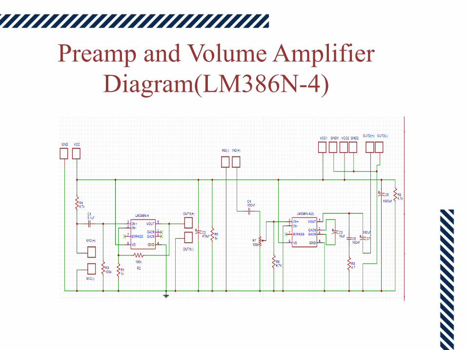
Preamp and Volume Amplifier
Diagram(LM386N-4)

Preamp and Volume Amplifier PCB

PT2399 Delay Chip
● Echo Digital Chip (ADC and DAC)
● Memory Storage: 44Kbit RAM
● Voltage Supply: 4.5V – 5.5V
● Voltage Gain: 0.5dB - 2.5dB
● Output Noise Voltage: -95 dBV - -80 dBV
● Pin 6: VCO uses to change the delay time
by put a potentiometer

PT2399 Circuit Diagram

PT2399 Delay PCB Board

Echo Amplifier Prototype

Stereo Amplifier - Bass and Treble
Amplifier (TDA1524A)
● To tone control the sound
● Volume control, Balance, Bass and Treble tone controls.
● 20 dB of voltage gain, +/-15 dB of bass and treble control
● 12 Vdc Voltage Supply

Test Curves

Tone Control Schematic Circuit

Tone Control PCB board
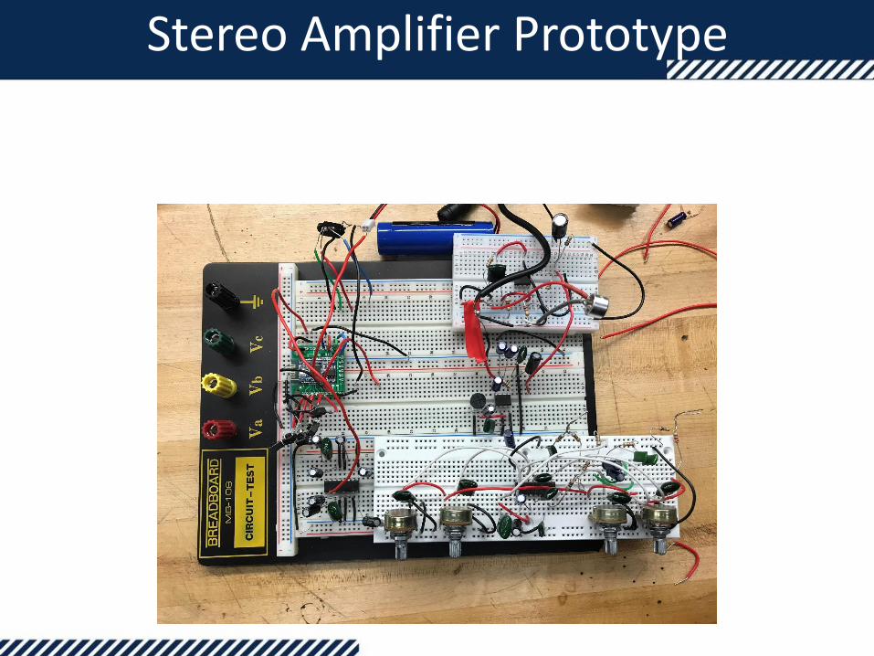
Stereo Amplifier Prototype

Instrumental (Beat) Music

Wireless Technology
● Wireless connection from electronic device (phone, laptop, tablet ,etc.)
● Bluetooth technology with short range consumes less energy, fit for portable device.
● BK8000L Bluetooth Module is chosen for this project

BK8000L Stereo Bluetooth Module
Specification:Manufacturer Details
Power Supply 2.8-5V
Brand Sparkfun
Interface I2C & UART
Frequency Range 2.4GHz ~ 2.480GHz
Price $4
Wireless Transmission Range
<10 meters
Bluetooth Type V2.1+EDR
Dimension 13.5 mm x 25 mm x 1.5 mm

BK8000L Schematic

Power System
5V
5V
5V
5V
5V
12 V
12 V
12 V
12 V

Power
● We have multiple boards.
● Extra board for power distribution does not fit into the project box
● Voltage regulator for each board.
● Using battery with 12V voltage supply.

Lithium-Ion Battery
• Rechargeable
• High energy density
• High capacity 9800mAH
• Low self-discharge
• Durable
• 10.8 – 12.6 V

LM3622 Battery Charger Circuit

Charging Characteristic

Power Consumption Calculation
Qty. Devices Working Current (mA) Total Consumption (mA)
2 Pre-Amplifier (LM386) 4 8
2 Amplifier (LM386) 4 8
1 Tone Control (TDA1524) 50 50
1 Speakers 4 Ohms 5W 312 624
1 Speakers 4 Ohms 10W 625 625
1 Echo (PT2399) 100 100
1 Bluetooth Module 45 45
TOTAL 1460
Battery = 9800 mAh ≈ 7 hours

LED DISPLAY

LED Display Goals
• Map frequency to an LED
• Multiple modes and color– Simple light show with configurable tempo
– Random pattern and random color
• No noticeable delay in light
• Light changing speed, that can be changed to either slow or fast
• Provide an effective lighting show, that could also aid in instruction and guidance for aspiring singers.

LED Display Block Diagram

EMBEDDED TECHNOLOGIES
DSP
PROS• optimized for fast operational
needs• Can process data in real time• Ideal for audio signal processing
CONS• Proprietary software• Configuration of DSP chips can be
complex • Expensive break out boards
PROS• Reprogrammable chips • Provide hardware-timed speed
and reliability• Parallel in nature
CONS• Volatile memory• Power consumption• Requires more components
PROS• Familiarity • Endless resource because of the
open source nature.• Onboard Memory
ATMEGA328ATMEGA2560
MCUFPGA

ADC121S01: Analog to Digital Converter
Reason for chip selection:
• Highest resolutions, highest speeds• Relatively cheap, only falling second by three cents to the Analog Devices
AD7478

RGB LED - Worldsemi
• Part: WS2812B
• Addressable RGB LED
• LEDs are configured to work well with the WS2811 driver.
• Input voltage: 5
• 20 mA of current draw
• Small in size

NeoPixel: 64 RGB LED Pixel Matrix
• 64 LEDs each with threeoutputs (R, G, B). Anintegrated driver is used toconfigure the LEDs.
• WS2811 driver: 3 channelconstant current LED driveIC
• LED power supply voltage upto 10V
• Scan frequency not less than400Hz/s

Powering the LED Display
LED’sLED
DRIVER
PER UNIT TOTAL
Min Voltage Max Voltage Max
Amperage
TLC5955 -3V +5.5V 29mA 60mA
ADC121S101 +2.7V 5.25V 3.2mA
MIC 1555 +2.7V +18V 300µA
ATMEGA
2560
4.5V 5.5V 2.0mA
OPA376 2.2V 5.5V 1mA
LEDs 20mA 480mA
LM2596
LM3940

LED Display PCB -ADC
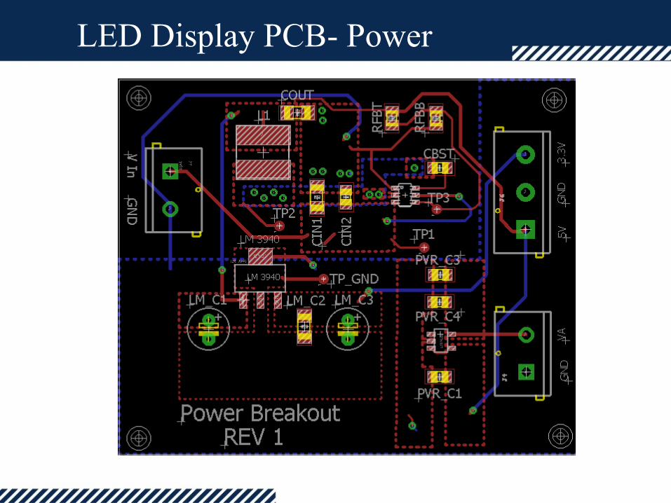
LED Display PCB- Power

LED Display PCB

LED Display PCB

LED Display PCB

Progress
100%
100%
100%
100%
100%
0% 20% 40% 60% 80% 100% 120%
RESEARCH
DESIGN
PROTOTYPING
TESTING
TOTAL

Budget
KPM Parts List
DescriptionPrice per
Unit
Developing
Amount
Developing
TotalProject Amount Project Total
Charging Cable Donate 1 $0 1 $0
TDA1524A $2 10 $20 1 $2
PT2399 $2 10 $20 1 $2
LM386 $3 10 $30 2 $6
Audio/Recording Cable Donate 1 $0 1 $0
PCB Boards $20 10 $200 6 $120
Electret Microphone $2 10 $20 2 $4
Cover (Fiber Glass) $100 0 0 1 $100
Speakers $8 5 $40 3 $24
Rechargeable Battery $20 2 $40 1 $20
Bluetooth Module $15 3 $45 1 $15
Microcontroller $15 1 $15 1 $15
LEDs $0.75 30 $40 30 $40
Misc. $30 2 $60 1 $30
TOTAL $530 $378

Challenges vs. Solutions
Challenges Solutions
Noise + Distortion - Research and build filter to the amplifiers
Many circuits -> Errors - The case can be opened to repair PCBs.
Huge PCB board + Small and Portable Device
- Separate the circuits into 4 PCB boards and mount them on the case.-Easy to find error.

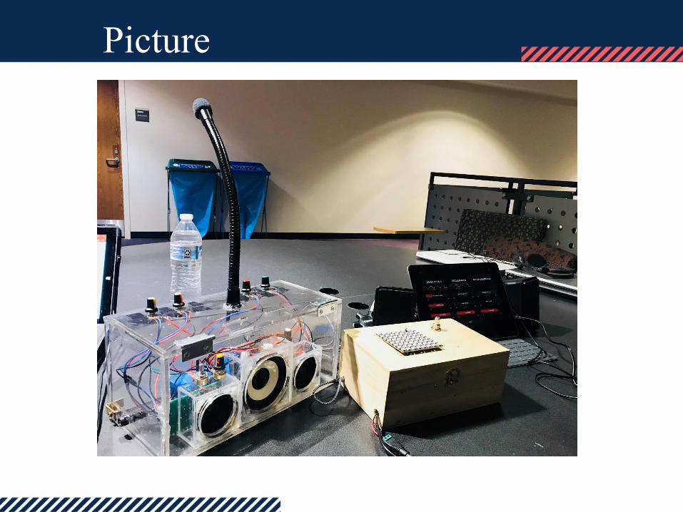
Picture
BACK FRONT
TOP
Picture

Video
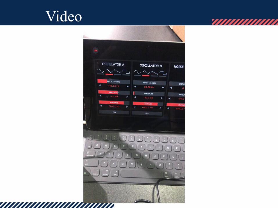
Video

What’s next?
● Create Website
● Complete paper
● Graduate

QUESTIONS?