
. Motion Control . axis positioning tasks . compact Drive ... · Highlights Complete drive system...
150
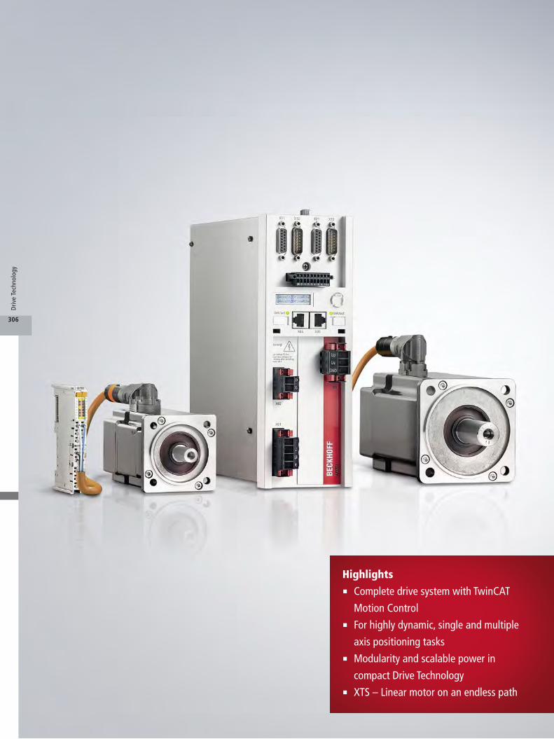
Highlights . Complete drive system with TwinCAT Motion Control . For highly dynamic, single and multiple axis positioning tasks . Modularity and scalable power in compact Drive Technology . XTS – Linear motor on an endless path 306 Drive Technology
Transcript of . Motion Control . axis positioning tasks . compact Drive ... · Highlights Complete drive system...
Highlights . Complete drive system with TwinCAT
Motion Control . For highly dynamic, single and multiple
axis positioning tasks . Modularity and scalable power in
compact Drive Technology . XTS – Linear motor on an endless path
306
Driv
e Te
chno
logy

362
354
396
392
378
366
402
406
407
350
386
388
389
390
391
418
395
356
360
361
359
364
400
386
410
428
448
430
434
435
438
414
412
413
418
424
427
420
432
440
441
442
444
445
446
450
454
452
Drive TechnologyThe drive system for highly dynamic positioning tasks
u www.beckhoff.com/DriveTechnology
308
324
334
343
346
346
347
336
348
348
321
320
322
320
349
340
339
338
350
342
344
Servo Drives
Multi-axis servo system
AX8000
Power supply modules AX86xx
Axis modules AX81xx, AX82xx
Option modules AX88xx
Motor cables
Accessories
Digital Compact Servo Drives
AX5000
1-channel up to 40 A AX51xx
1-channel 60 up to 170 A
2-channel up to 6 A AX52xx
Encoder option cards AX57xx
TwinSAFE drive option cards
AX58xx
AX-Bridge quick connection
system AX59xx
Supply cables
Distributed Servo Drive
system
Distributed Servo Drive AMP80xx
Coupling modules AX503x,
AX883x
Distribution module AMP8805
Cables
Servo and Linear Motors
Synchronous Servomotors
Motor series AM8000
Motor series with higher
moment of inertia AM8500
Stainless steel motor series
AM8800
Motor series AM3000
Supply cables
Linear Servomotors
Linear Servomotors AL2xxx
Accessories
Supply cables
Planetary gear units
High-end gear series AG2300
Economy planetary gear units
AG3300
Economy planetary gear units
AG3210
High-end planetary gear units
with output flange AG2400
Economy planetary gear units
with output flange AG3400
Stainless steel planetary gear
units AG2800
Planetary gear units AG2250
Compact Drive Technology
Linear actuator AA1121
Supply cables for AA1121
Servomotor series AM8100
Planetary gear units AG2250
Stepper motors AS2000
Stepper motors AS1000
Planetary gear units AG1000
XTS
(eXtended Transport System)
XTS Standard
Motor modules AT20xx-0xxx
Movers AT9011, AT9012
Guide rails AT90xx, AT91xx
Starter kit AT2000-xx00
XTS Black Line
Motor modules
AT20xx-0xxx-000x
XTS Hygienic
Motor modules ATH20xx-0xxx
Mover ATH9011
Guide rails ATH90xx, ATH91xx
Software
TC3 Motion Designer TE5910
TC3 Drive Manager 2 TE5950
TC3 XTS Extension TF5850
Product overviews
Technologies
One Cable Technology (OCT)
Fan-cooled motors
TwinSAFE
XTS (eXtended Transport
System)
307
Driv
e Te
chno
logy
AX8000
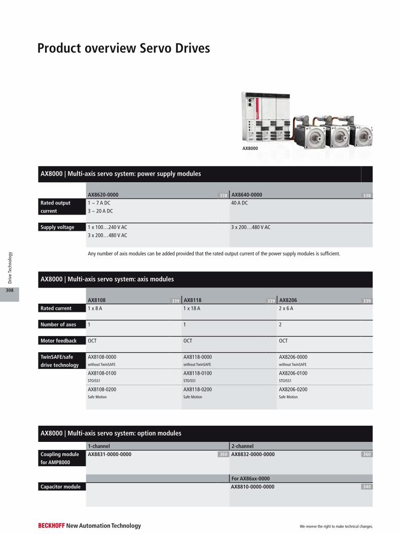
AX8000 | Multi-axis servo system: power supply modules
AX8620-0000 338 AX8640-0000 338
Rated output
current
1 ~ 7 A DC
3 ~ 20 A DC
40 A DC
Supply voltage 1 x 100…240 V AC
3 x 200…480 V AC
3 x 200…480 V AC
AX8000 | Multi-axis servo system: axis modules
AX8108 339 AX8118 339 AX8206 339
Rated current 1 x 8 A 1 x 18 A 2 x 6 A
Number of axes 1 1 2
Motor feedback OCT OCT OCT
TwinSAFE/safe
drive technology
AX8108-0000 AX8118-0000 AX8206-0000without TwinSAFE without TwinSAFE without TwinSAFE
AX8108-0100 AX8118-0100 AX8206-0100STO/SS1 STO/SS1 STO/SS1
AX8108-0200 AX8118-0200 AX8206-0200Safe Motion Safe Motion Safe Motion
Any number of axis modules can be added provided that the rated output current of the power supply modules is sufficient.
AX8000 | Multi-axis servo system: option modules
1-channel 2-channel
Coupling module
for AMP8000
AX8831-0000-0000 360 AX8832-0000-0000 360
For AX86xx-0000
Capacitor module AX8810-0000-0000 340
Product overview Servo Drives
We reserve the right to make technical changes.
308
Driv
e Te
chno
logy

AX5000 | Digital Compact Servo Drives
AX5101…AX5112 346 AX5201…AX5206 347 AX5118…AX5140 346 AX5160…AX5193 346
Number of axes 1 2 1 1
Rated current 1.5…12 A 2 x 1.5…6 A 18…40 A 60…170 A
Supply voltage 3 x 100…480 V AC
(wide voltage range),
1 x 100…240 V AC
3 x 100…480 V AC
(wide voltage range),
1 x 100…240 V AC
3 x 100…480 V AC
(wide voltage range)
3 x 400…480 V AC
Motor feedback OCT, multi-feedback OCT, multi-feedback OCT, multi-feedback multi-feedback
AX5000 | Digital Compact Servo Drives: options
1-channel 2-channel
Coupling module
for AMP8000
AX5031-0000-0200 360 AX5032-0000-0200 360
Encoder option
cards
AX5701 348 AX5721 348 AX5702 348 AX5722 348
1 VPP, BiSS B, Hiperface, EnDat EnDat 2.2, BiSS C 1 VPP, BiSS B, Hiperface, EnDat EnDat 2.2, BiSS C
STO/SS1 Safe Motion
TwinSAFE/safe
drive technology
AX5801-0200 348 AX5805-0000 348 AX5806-0000 348
for AX5101…AX5140 and
AX5201…AX5206
for AX5101…AX5140 and
AX5201…AX5206
for AX5160…AX5193
Power supply Power distribution
AX-Bridge AX5901 349 AX5902 349 AX5911 349 AX5912 349
for AX5101…AX5125 and
AX5201…AX5206
for AX5140 for AX5101…AX5112 and
AX5201…AX5206
for AX5118 and AX5125
Brake energy recovery
Brake module AX5021 353
connection of external brake resistors
AX5000
We reserve the right to make technical changes.
309
Driv
e Te
chno
logy
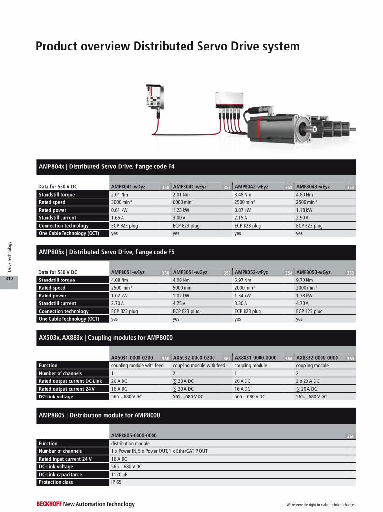
AMP804x | Distributed Servo Drive, flange code F4
Data for 560 V DC AMP8041-wDyz 358 AMP8041-wEyz 358 AMP8042-wEyz 358 AMP8043-wEyz 358
Standstill torque 2.01 Nm 2.01 Nm 3.48 Nm 4.80 Nm
Rated speed 3000 min-1 6000 min-1 2500 min-1 2500 min-1
Rated power 0.61 kW 1.23 kW 0.87 kW 1.18 kW
Standstill current 1.65 A 3.00 A 2.15 A 2.90 A
Connection technology ECP B23 plug ECP B23 plug ECP B23 plug ECP B23 plug
One Cable Technology (OCT) yes yes yes yes
AMP805x | Distributed Servo Drive, flange code F5
Data for 560 V DC AMP8051-wEyz 358 AMP8051-wGyz 358 AMP8052-wFyz 358 AMP8053-wGyz 358
Standstill torque 4.08 Nm 4.08 Nm 6.97 Nm 9.70 Nm
Rated speed 2500 min-1 5000 min-1 2000 min-1 2000 min-1
Rated power 1.02 kW 1.02 kW 1.34 kW 1.78 kW
Standstill current 2.70 A 4.75 A 3.30 A 4.70 A
Connection technology ECP B23 plug ECP B23 plug ECP B23 plug ECP B23 plug
One Cable Technology (OCT) yes yes yes yes
AX503x, AX883x | Coupling modules for AMP8000
AX5031-0000-0200 360 AX5032-0000-0200 360 AX8831-0000-0000 360 AX8832-0000-0000 360
Function coupling module with feed coupling module with feed coupling module coupling module
Number of channels 1 2 1 2
Rated output current DC-Link 20 A DC ∑ 20 A DC 20 A DC 2 x 20 A DC
Rated output current 24 V 16 A DC ∑ 20 A DC 16 A DC ∑ 20 A DC
DC-Link voltage 565…680 V DC 565…680 V DC 565…680 V DC 565…680 V DC
AMP8805 | Distribution module for AMP8000
AMP8805-0000-0000 361
Function distribution module
Number of channels 1 x Power IN, 5 x Power OUT, 1 x EtherCAT P OUT
Rated input current 24 V 16 A DC
DC-Link voltage 565…680 V DC
DC-Link capacitance 1120 µF
Protection class IP 65
Product overview Distributed Servo Drive system
We reserve the right to make technical changes.
310
Driv
e Te
chno
logy

Product overview Synchronous Servomotors
*Please note the different flange size.
*Please note the different flange size.
Synchronous Servomotors, OCT
Flange code
F1 (40 mm) F2 (58 mm) F3 (72 mm) F4 (87 mm) F5 (104 mm) F6 (142 mm) F7 (197 mm)
Standard
400 V AC
AM802x AM803x AM804x AM805x AM806x AM807x 366
M0 = 0.50…1.20 Nm M0 = 1.37…3.22 Nm M0 = 2.37…5.65 Nm M0 = 4.80…11.4 Nm,
up to 15.4 Nm with fan
M0 = 12.8…35.0 Nm,
up to 49.0 Nm with fan
M0 = 29.0…92.0 Nm,
up to 129 Nm with fan
Standard
230 V AC
AM801x 366
M0 = 0.20…0.52 Nm
Standard
48 V DC
AM811x AM812x AM813x AM8141 414
M0 = 0.20…0.52 Nm M0 = 0.50…0.80 Nm M0 = 1.35…2.37 Nm M0 = 2.40 Nm
Increased
inertia
400 V AC
AM853x AM854x AM855x AM856x 378
M0 = 1.37…3.22 Nm M0 = 2.37…5.65 Nm M0 = 4.80…11.4 Nm,
up to 15.4 Nm with fan
M0 = 12.8…29.0 Nm,
up to 41.4 Nm with fan
Stainless
steel
400 V AC
AM883x* AM884x* AM885x* AM886x* 392
M0 = 0.85…1.85 Nm M0 = 1.60…3.50 Nm M0 = 3.10…6.40 Nm M0 = 7.75…16.7 Nm
Synchronous Servomotors, 2-cable standard
Flange code
F1 (40 mm) F2 (58 mm) F3 (72 mm) F4 (87 mm) F5 (104 mm) F6 (142 mm) F7 (197 mm) F8 (260 mm)
Standard
400 V AC
AM802x AM803x AM804x AM805x AM806x AM807x 366
M0 = 0.50…1.20 Nm M0 = 1.37…3.22 Nm M0 = 2.37…5.65 Nm M0 = 4.80…11.4 Nm,
up to 15.4 Nm with fan
M0 = 12.8…35.0 Nm,
up to 49.0 Nm with fan
M0 = 29.0…92.0 Nm,
up to 129 Nm with fan
AM302x AM303x* AM304x* AM305x* AM306x* AM307x* AM308x 396
M0 = 0.87…1.41 Nm M0 = 1.15…2.79 Nm M0 = 1.95…6.00 Nm M0 = 4.70…14.9 Nm M0 = 11.9…25.0 Nm M0 = 29.7…53.0 Nm M0 = 75.0…180 Nm
Standard
230 V AC
AM301x AM302x AM3031 396
M0 = 0.18…0.41 Nm M0 = 0.48…0.87 Nm M0 = 1.20 Nm
AM801x 368
M0 = 0.20…0.52 Nm
Standard
48 V DC
AM811x AM812x AM813x AM8141 414
M0 = 0.20…0.52 Nm M0 = 0.50…0.80 Nm M0 = 1.35…2.37 Nm M0 = 2.40 Nm
Increased
inertia
400 V AC
AM853x AM854x AM855x AM856x 378
M0 = 1.37…3.22 Nm M0 = 2.37…5.65 Nm M0 = 4.80…11.4 Nm,
up to 15.4 Nm with fan
M0 = 12.8…29.0 Nm,
up to 41.4 Nm with fan
AM354x* AM355x* AM356x*M0 = 1.90…4.20 Nm M0 = 4.10…8.60 Nm M0 = 11.6…14.9 Nm
Stainless
steel
400 V AC
AM883x* AM884x* AM885x* AM886x* 392
M0 = 0.85…1.85 Nm M0 = 1.60…3.50 Nm M0 = 3.10…6.40 Nm M0 = 7.75…16.7 Nm
AM8000, AM8500 with fanAM8000, AM8500
We reserve the right to make technical changes.
311
Driv
e Te
chno
logy
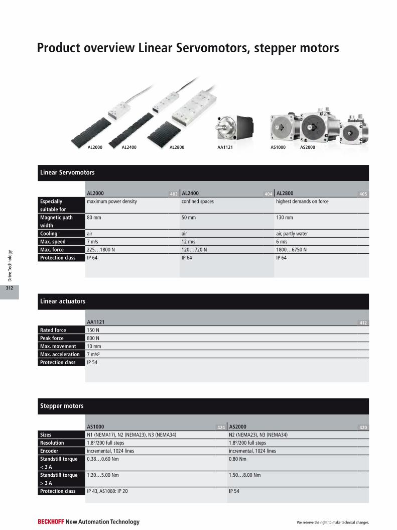
AL2400AL2000 AL2800 AS2000AS1000AA1121
Product overview Linear Servomotors, stepper motors
Linear Servomotors
AL2000 403 AL2400 404 AL2800 405
Especially
suitable for
maximum power density confined spaces highest demands on force
Magnetic path
width
80 mm 50 mm 130 mm
Cooling air air air, partly water
Max. speed 7 m/s 12 m/s 6 m/s
Max. force 225…1800 N 120…720 N 1800…6750 N
Protection class IP 64 IP 64 IP 64
Stepper motors
AS1000 424 AS2000 420
Sizes N1 (NEMA17), N2 (NEMA23), N3 (NEMA34) N2 (NEMA23), N3 (NEMA34)
Resolution 1.8°/200 full steps 1.8°/200 full steps
Encoder incremental, 1024 lines incremental, 1024 lines
Standstill torque
< 3 A
0.38…0.60 Nm 0.80 Nm
Standstill torque
> 3 A
1.20…5.00 Nm 1.50…8.00 Nm
Protection class IP 43, AS1060: IP 20 IP 54
Linear actuators
AA1121 412
Rated force 150 N
Peak force 800 N
Max. movement 10 mm
Max. acceleration 7 m/s²
Protection class IP 54
We reserve the right to make technical changes.
312
Driv
e Te
chno
logy
AG2300AG3210 AG3300 AG2400 AG3400 AG2800 AG2250 AG1000
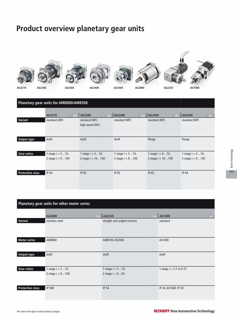
Product overview planetary gear units
Planetary gear units for AM8000/AM8500
AG3210 389 AG2300 386 AG3300 388 AG2400 390 AG3400 391
Variant standard (MF) standard (MF), standard (MF) standard (MF) standard (MF)
high-speed (MC)
Output type shaft shaft shaft flange flange
Gear ratios 1-stage i = 3…10,
2-stage i = 9…100
1-stage i = 3…10,
2-stage i = 16…100
1-stage i = 3…10,
2-stage i = 9…100
1-stage i = 4…10,
2-stage i = 16…100
1-stage i = 3…10,
2-stage i = 9…100
Protection class IP 64 IP 65 IP 65 IP 65 IP 64
Planetary gear units for other motor series
AG2800 395 AG2250 418 AG1000 427
Variant stainless steel straight and angled versions standard
Motor series AM8800 AM8100, AS2000 AS1000
Output type shaft shaft shaft
Gear ratios 1-stage i = 3…10,
2-stage i = 9…100
1-stage i = 3…10,
2-stage i = 9…64
1-stage i = 3.7 or 6.75
Protection class IP 69K IP 54 IP 43, AS1060: IP 20
We reserve the right to make technical changes.
313
Driv
e Te
chno
logy

Product overview compact Drive Technology
Product group BLDC motor DC motor Stepper motor Servomotor
4.5…8 A < 3 A 3…5 A > 5 A < 3 A 3…5 A > 5 A < 3 A 3…5 A > 5 A
I/O EtherCAT
Terminals
IP 20
EL7411-9014 2 232 EL7332 2 231 EL7332 + 2 231 EL7037 2 227 EL7037 + ZB8610 2 227 EL7201-9014 2 229 EL7201-9014 + 2 229 EL7221-9014 2 228
Irms = 4.5 A, 50 V DC, STO Imax = 1.0 A, 24 V DC ZB8610 Imax = 1.5 A, 24 V DC, incremental encoder,
vector control
Imax = 3.0 A, 24 V DC, incremental encoder,
vector control
Irms = 2.8 A, 50 V DC, OCT, STO ZB8610 Irms = 7…8 A with ZB8610,
50 V DC, OCT, STOImax = 3.0 A, 24 V DC Irms = 4.5 A, 50 V DC, OCT, STO
EL7411-9014 +
ZB8610
2 232 EL7342 2 231 EL7342 + 2 231 EL7031 2 226 EL7047-9014 2 227 EL7047-9014 + 2 227 EL7201-0010 2 229 EL7201-0010 + 2 229
Imax = 3.5 A, 50 V DC,
incremental encoder
ZB8610 Imax = 6.5 A, Imax = 1.5 A, 24 V DC Imax = 5.0 A, 50 V DC, incremental encoder,
vector control, STO
ZB8610 Imax = 6.5 A, 50 V DC, Irms = 2.8 A, 50 V DC, OCT ZB8610Irms = 7…8 A, 50 V DC, STO 50 V DC, incremental encoder incremental encoder, vector control, STO Irms = 4.5 A, 50 V DC, OCT
EL7047 2 227 EL7047 + ZB8610 2 227 EL7201 2 229 EL7201 + ZB8610 2 229
Imax = 5.0 A, 50 V DC, incremental encoder,
vector control
Imax = 6.5 A, 50 V DC, incremental encoder,
vector control
Irms = 2.8 A, 50 V DC, resolver Irms = 4.5 A, 50 V DC, resolver
EL7041 2 227 EL7211-9014 2 229
Imax = 5.0 A, 50 V DC, incremental encoder Irms = 4.5 A, 50 V DC, OCT, STO
EL7211-0010 2 229
Irms = 4.5 A, 50 V DC, OCT
EL7211 2 229
Irms = 4.5 A, 50 V DC, resolver
EtherCAT Plug-in
Modules
IP 20
EJ7342 Imax = 3.5 A, 2 393 EJ7031 2 391 EJ7047 Imax = 5.0 A, 50 V DC, 2 391 EJ7211-9414 2 392
50 V DC, incremental encoder Imax = 1.5 A, 24 V DC incremental encoder, vector control Irms = 4.5 A, 50 V DC, OCT, STO, TwinSAFE SC
EJ7041-0052 2 391 EJ7211-0010 2 392
Imax = 5.0 A, 50 V DC Irms = 4.5 A, 50 V DC, OCT
Bus Terminals
IP 20
KL2532 2 483 KL2552 Imax = 5.0 A, 2 483 KL2531 2 481 KL2541 2 481
Imax = 1.0 A, 24 V DC 50 V DC, incremental encoder Imax = 1.5 A, 24 V DC Imax = 5.0 A, 50 V DC, incremental encoder
EtherCAT Box
modules IP 67
EP/ER7342-0002 2 314 EP/ER7041-1002 2 312 EP/ER7041-3002 2 313 EP7211-9034 2 311
Imax = 3.5 A, 50 V DC Imax = 1.5 A, 50 V DC, incremental encoder Imax = 5.0 A, 50 V DC, incremental encoder Irms = 4.5 A, 50 V DC, OCT, STO
EtherCAT P Box
modules IP 67
EPP7342-0002 2 352 EPP7041-1002 2 351 EPP7041-3002 2 351
Imax = 3.5 A, 50 V DC Imax = 1.5 A, 50 V DC, incremental encoder Imax = 5.0 A, 50 V DC, incremental encoder
Mot
ion Flange code
F1 (40 mm),
N1 (NEMA17)
AS1010 424 AM8111-wFyz 414 AM8112-wFyz 414
1.0 A, 48 V DC, 0.38 Nm 2.8 A, 48 V DC, 0.20 Nm, 4000 min-1 4.7 A, 48 V DC, 0.38 Nm, 4500 min-1
AS1020 424 AM8113-wFyz 414
1.0 A, 48 V DC, 0.50 Nm 4.8 A, 48 V DC, 0.52 Nm, 3000 min-1
Flange code
F2 (58 mm),
N2 (NEMA23)
AS1030 424 AS1050 424 AS2022-0Hy0 420 AM8121-wFyz 414
1.5 A, 48 V DC, 0.60 Nm 5.0 A, 48 V DC, 1.20 Nm 5.6 A, 48 V DC, 1.50 Nm 4.0 A, 48 V DC, 0.50 Nm, 3000 min-1
AS2021-0Dy0 420 AS2023-0Hy0 420 AM8122-wFyz 414 AM8122-wJyz 414
2.0 A, 48 V DC, 0.80 Nm 5.6 A, 48 V DC, 1.80 Nm 4.0 A, 48 V DC, 0.80 Nm, 2000 min-1 8.0 A, 48 V DC, 0.80 Nm, 4500 min-1
Flange code
F3 (72 mm),
N3 (NEMA34)
AS1060 424 AS2041-1Hy0 420 AM8131-wFyz 414 AM8131-wJyz 414
5.0 A, 48 V DC, 5.00 Nm 5.6 A, 48 V DC, 3.30 Nm 5.0 A, 48 V DC, 1.35 Nm, 1000 min-1 8.0 A, 48 V DC, 1.35 Nm, 1800 min-1
AS2042-1Hy0 420 AM8132-wJyz 414
5.6 A, 48 V DC, 6.40 Nm 8.0 A, 48 V DC, 2.37 Nm, 1000 min-1
AS2043-1Jy0 420
6.5 A, 48 V DC, 8.00 Nm
Flange code
F4 (87 mm)
AM8141-wJyz 414
8.0 A, 48 V DC, 2.40 Nm, 1000 min-1
EtherCAT Terminals EtherCAT Plug-in Modules
Bus Terminals EtherCAT Box modules EtherCAT P Boxmodules
We reserve the right to make technical changes.
314
Driv
e Te
chno
logy

Product group BLDC motor DC motor Stepper motor Servomotor
4.5…8 A < 3 A 3…5 A > 5 A < 3 A 3…5 A > 5 A < 3 A 3…5 A > 5 A
I/O EtherCAT
Terminals
IP 20
EL7411-9014 2 232 EL7332 2 231 EL7332 + 2 231 EL7037 2 227 EL7037 + ZB8610 2 227 EL7201-9014 2 229 EL7201-9014 + 2 229 EL7221-9014 2 228
Irms = 4.5 A, 50 V DC, STO Imax = 1.0 A, 24 V DC ZB8610 Imax = 1.5 A, 24 V DC, incremental encoder,
vector control
Imax = 3.0 A, 24 V DC, incremental encoder,
vector control
Irms = 2.8 A, 50 V DC, OCT, STO ZB8610 Irms = 7…8 A with ZB8610,
50 V DC, OCT, STOImax = 3.0 A, 24 V DC Irms = 4.5 A, 50 V DC, OCT, STO
EL7411-9014 +
ZB8610
2 232 EL7342 2 231 EL7342 + 2 231 EL7031 2 226 EL7047-9014 2 227 EL7047-9014 + 2 227 EL7201-0010 2 229 EL7201-0010 + 2 229
Imax = 3.5 A, 50 V DC,
incremental encoder
ZB8610 Imax = 6.5 A, Imax = 1.5 A, 24 V DC Imax = 5.0 A, 50 V DC, incremental encoder,
vector control, STO
ZB8610 Imax = 6.5 A, 50 V DC, Irms = 2.8 A, 50 V DC, OCT ZB8610Irms = 7…8 A, 50 V DC, STO 50 V DC, incremental encoder incremental encoder, vector control, STO Irms = 4.5 A, 50 V DC, OCT
EL7047 2 227 EL7047 + ZB8610 2 227 EL7201 2 229 EL7201 + ZB8610 2 229
Imax = 5.0 A, 50 V DC, incremental encoder,
vector control
Imax = 6.5 A, 50 V DC, incremental encoder,
vector control
Irms = 2.8 A, 50 V DC, resolver Irms = 4.5 A, 50 V DC, resolver
EL7041 2 227 EL7211-9014 2 229
Imax = 5.0 A, 50 V DC, incremental encoder Irms = 4.5 A, 50 V DC, OCT, STO
EL7211-0010 2 229
Irms = 4.5 A, 50 V DC, OCT
EL7211 2 229
Irms = 4.5 A, 50 V DC, resolver
EtherCAT Plug-in
Modules
IP 20
EJ7342 Imax = 3.5 A, 2 393 EJ7031 2 391 EJ7047 Imax = 5.0 A, 50 V DC, 2 391 EJ7211-9414 2 392
50 V DC, incremental encoder Imax = 1.5 A, 24 V DC incremental encoder, vector control Irms = 4.5 A, 50 V DC, OCT, STO, TwinSAFE SC
EJ7041-0052 2 391 EJ7211-0010 2 392
Imax = 5.0 A, 50 V DC Irms = 4.5 A, 50 V DC, OCT
Bus Terminals
IP 20
KL2532 2 483 KL2552 Imax = 5.0 A, 2 483 KL2531 2 481 KL2541 2 481
Imax = 1.0 A, 24 V DC 50 V DC, incremental encoder Imax = 1.5 A, 24 V DC Imax = 5.0 A, 50 V DC, incremental encoder
EtherCAT Box
modules IP 67
EP/ER7342-0002 2 314 EP/ER7041-1002 2 312 EP/ER7041-3002 2 313 EP7211-9034 2 311
Imax = 3.5 A, 50 V DC Imax = 1.5 A, 50 V DC, incremental encoder Imax = 5.0 A, 50 V DC, incremental encoder Irms = 4.5 A, 50 V DC, OCT, STO
EtherCAT P Box
modules IP 67
EPP7342-0002 2 352 EPP7041-1002 2 351 EPP7041-3002 2 351
Imax = 3.5 A, 50 V DC Imax = 1.5 A, 50 V DC, incremental encoder Imax = 5.0 A, 50 V DC, incremental encoder
Mot
ion Flange code
F1 (40 mm),
N1 (NEMA17)
AS1010 424 AM8111-wFyz 414 AM8112-wFyz 414
1.0 A, 48 V DC, 0.38 Nm 2.8 A, 48 V DC, 0.20 Nm, 4000 min-1 4.7 A, 48 V DC, 0.38 Nm, 4500 min-1
AS1020 424 AM8113-wFyz 414
1.0 A, 48 V DC, 0.50 Nm 4.8 A, 48 V DC, 0.52 Nm, 3000 min-1
Flange code
F2 (58 mm),
N2 (NEMA23)
AS1030 424 AS1050 424 AS2022-0Hy0 420 AM8121-wFyz 414
1.5 A, 48 V DC, 0.60 Nm 5.0 A, 48 V DC, 1.20 Nm 5.6 A, 48 V DC, 1.50 Nm 4.0 A, 48 V DC, 0.50 Nm, 3000 min-1
AS2021-0Dy0 420 AS2023-0Hy0 420 AM8122-wFyz 414 AM8122-wJyz 414
2.0 A, 48 V DC, 0.80 Nm 5.6 A, 48 V DC, 1.80 Nm 4.0 A, 48 V DC, 0.80 Nm, 2000 min-1 8.0 A, 48 V DC, 0.80 Nm, 4500 min-1
Flange code
F3 (72 mm),
N3 (NEMA34)
AS1060 424 AS2041-1Hy0 420 AM8131-wFyz 414 AM8131-wJyz 414
5.0 A, 48 V DC, 5.00 Nm 5.6 A, 48 V DC, 3.30 Nm 5.0 A, 48 V DC, 1.35 Nm, 1000 min-1 8.0 A, 48 V DC, 1.35 Nm, 1800 min-1
AS2042-1Hy0 420 AM8132-wJyz 414
5.6 A, 48 V DC, 6.40 Nm 8.0 A, 48 V DC, 2.37 Nm, 1000 min-1
AS2043-1Jy0 420
6.5 A, 48 V DC, 8.00 Nm
Flange code
F4 (87 mm)
AM8141-wJyz 414
8.0 A, 48 V DC, 2.40 Nm, 1000 min-1
Flange code N1Flange code F1 Flange code N2Flange code F2 Flange code F3 Flange code N3 Flange code F4
We reserve the right to make technical changes.
315
Driv
e Te
chno
logy
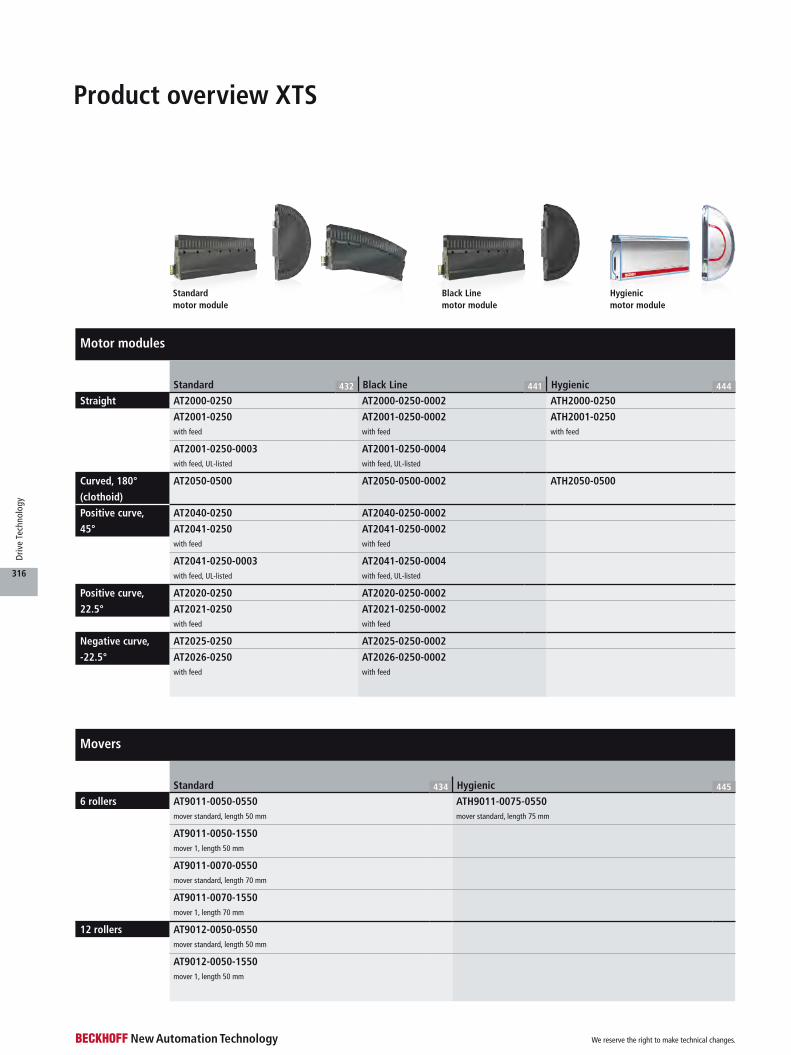
Motor modules
Standard 432 Black Line 441 Hygienic 444
Straight AT2000-0250 AT2000-0250-0002 ATH2000-0250
AT2001-0250 AT2001-0250-0002 ATH2001-0250with feed with feed with feed
AT2001-0250-0003 AT2001-0250-0004with feed, UL-listed with feed, UL-listed
Curved, 180°
(clothoid)
AT2050-0500 AT2050-0500-0002 ATH2050-0500
Positive curve,
45°
AT2040-0250 AT2040-0250-0002
AT2041-0250 AT2041-0250-0002with feed with feed
AT2041-0250-0003 AT2041-0250-0004with feed, UL-listed with feed, UL-listed
Positive curve,
22.5°
AT2020-0250 AT2020-0250-0002
AT2021-0250 AT2021-0250-0002 with feed with feed
Negative curve,
-22.5°
AT2025-0250 AT2025-0250-0002
AT2026-0250 AT2026-0250-0002with feed with feed
Product overview XTS
Movers
Standard 434 Hygienic 445
6 rollers AT9011-0050-0550 ATH9011-0075-0550mover standard, length 50 mm mover standard, length 75 mm
AT9011-0050-1550mover 1, length 50 mm
AT9011-0070-0550mover standard, length 70 mm
AT9011-0070-1550mover 1, length 70 mm
12 rollers AT9012-0050-0550mover standard, length 50 mm
AT9012-0050-1550mover 1, length 50 mm
Standard motor module
Black Linemotor module
Hygienicmotor module
We reserve the right to make technical changes.
316
Driv
e Te
chno
logy
Standardstarter kit
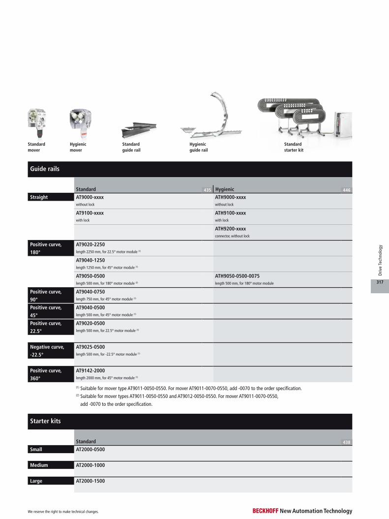
Guide rails
Standard 435 Hygienic 446
Straight AT9000-xxxx ATH9000-xxxxwithout lock without lock
AT9100-xxxx ATH9100-xxxxwith lock with lock
ATH9200-xxxxconnector, without lock
Positive curve,
180°
AT9020-2250length 2250 mm, for 22.5° motor module (1)
AT9040-1250length 1250 mm, for 45° motor module (1)
AT9050-0500 ATH9050-0500-0075length 500 mm, for 180° motor module (2) length 500 mm, for 180° motor module
Positive curve,
90°
AT9040-0750length 750 mm, for 45° motor module (1)
Positive curve,
45°
AT9040-0500length 500 mm, for 45° motor module (1)
Positive curve,
22.5°
AT9020-0500length 500 mm, for 22.5° motor module (1)
Negative curve,
-22.5°
AT9025-0500length 500 mm, for -22.5° motor module (1)
Positive curve,
360°
AT9142-2000length 2000 mm, for 45° motor module (1)
Starter kits
Standard 438
Small AT2000-0500
Medium AT2000-1000
Large AT2000-1500
Standardguide rail
Hygienicguide rail
Standardmover
Hygienicmover
(1) Suitable for mover type AT9011-0050-0550. For mover AT9011-0070-0550, add -0070 to the order specification.(2) Suitable for mover types AT9011-0050-0550 and AT9012-0050-0550. For mover AT9011-0070-0550,
add -0070 to the order specification.
We reserve the right to make technical changes.
317
Driv
e Te
chno
logy
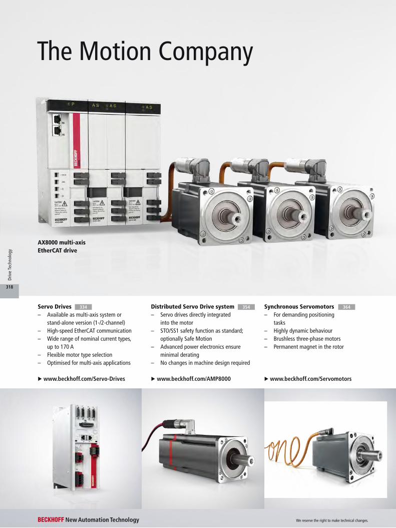
AX8000 multi-axis EtherCAT drive
The Motion Company
Synchronous Servomotors– For demanding positioning
tasks– Highly dynamic behaviour– Brushless three-phase motors– Permanent magnet in the rotor
u www.beckhoff.com/Servomotors
Servo Drives– Available as multi-axis system or
stand-alone version (1-/2-channel)– High-speed EtherCAT communication– Wide range of nominal current types,
up to 170 A– Flexible motor type selection– Optimised for multi-axis applications
u www.beckhoff.com/Servo-Drives
364Distributed Servo Drive system– Servo drives directly integrated
into the motor– STO/SS1 safety function as standard;
optionally Safe Motion– Advanced power electronics ensure
minimal derating– No changes in machine design required
u www.beckhoff.com/AMP8000
354334
We reserve the right to make technical changes.
318
Driv
e Te
chno
logy

– Scalable product range of servo drive technology
– Integrated safety technology in compliance with safety perfor-mance level PL e, integrated into compact Drive Technology up to safety performance level PL d
– As the pioneer of One Cable Tech-nology and the eXtended Trans-port System, Beckhoff specialises in manufacturing efficient, space-saving motion solutions.
In combination with the motion control solutions offered by
the company’s TwinCAT automation software, Beckhoff Drive Tech-
nology provides an advanced, all-inclusive drive system. PC-based
control technology from Beckhoff is ideally suited for single- and
multi-axis positioning tasks with high dynamic requirements.
The AX5000 and AX8000 Servo Drive series with high-performance
EtherCAT communication offer the best-possible performance and
dynamics. Servomotors with One Cable Technology (OCT), combin-
ing power and feedback systems into one standard motor cable,
reduce material and commissioning costs.
Compact Drive Technology– Solutions for up to 8 A in the
space-saving I/O system– Simple connection of stepper,
servo, DC or AC motors– IP 20 or IP 67 connection options– Matching motors and gearboxes
u www.beckhoff.com/ compact-drive-technology
eXtended Transport System XTS– Linear motor on an endless path– Replaces traditional mechanics with
advanced mechatronic solutions– Software-based functional changes– Individual product transport with
continuous material flow
u www.beckhoff.com/XTS
u www.beckhoff.com/DriveTechnology
410 428
We reserve the right to make technical changes.
319
Driv
e Te
chno
logy
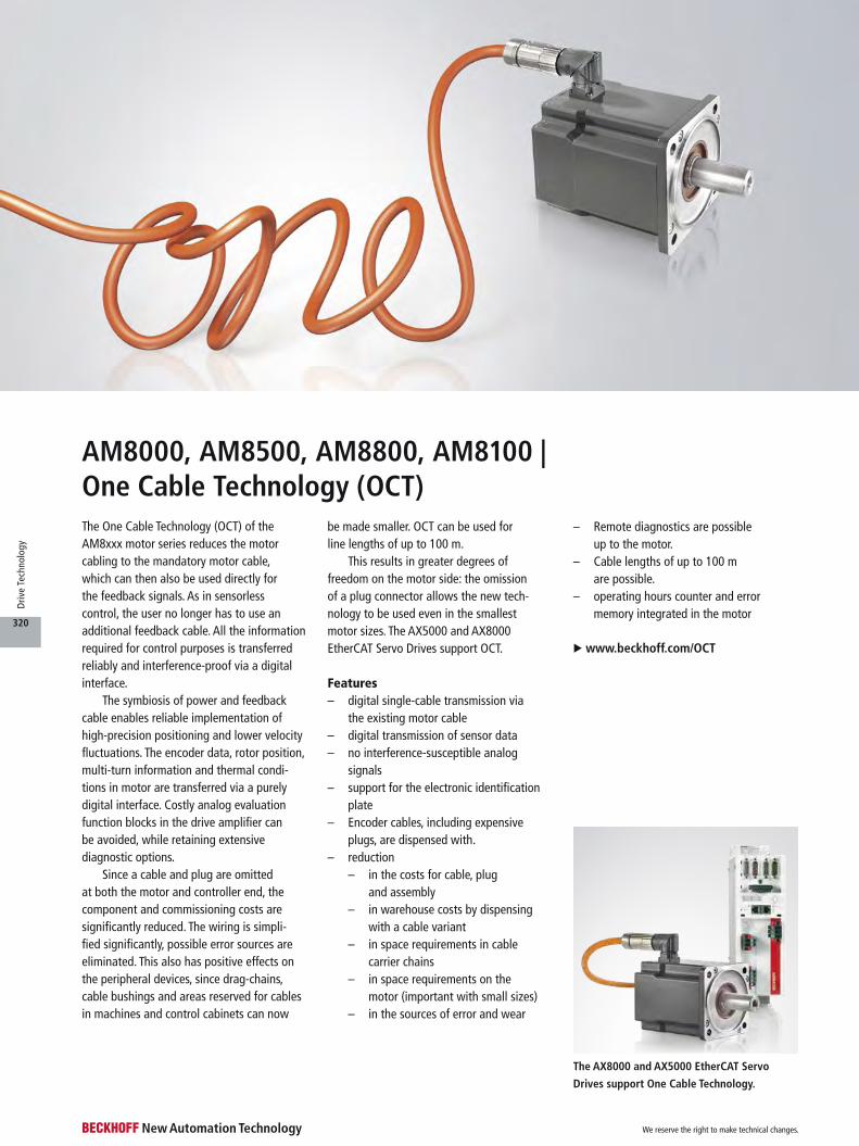
The One Cable Technology (OCT) of the AM8xxx motor series reduces the motor cabling to the mandatory motor cable, which can then also be used directly for the feedback signals. As in sensorless control, the user no longer has to use an additional feedback cable. All the information required for control purposes is transferred reliably and interference-proof via a digital interface.
The symbiosis of power and feedback cable enables reliable implementation of high-precision positioning and lower velocity fluctuations. The encoder data, rotor position, multi-turn information and thermal condi-tions in motor are transferred via a purely digital interface. Costly analog evaluation function blocks in the drive amplifier can be avoided, while retaining extensive diagnostic options.
Since a cable and plug are omitted at both the motor and controller end, the component and commissioning costs are significantly reduced. The wiring is simpli- fied significantly, possible error sources are eliminated. This also has positive effects on the peripheral devices, since drag-chains, cable bushings and areas reserved for cables in machines and control cabinets can now
be made smaller. OCT can be used for line lengths of up to 100 m.
This results in greater degrees of freedom on the motor side: the omission of a plug connector allows the new tech-nology to be used even in the smallest motor sizes. The AX5000 and AX8000 EtherCAT Servo Drives support OCT.
Features– digital single-cable transmission via
the existing motor cable– digital transmission of sensor data– no interference-susceptible analog
signals– support for the electronic identification
plate– Encoder cables, including expensive
plugs, are dispensed with.– reduction
– in the costs for cable, plug and assembly
– in warehouse costs by dispensing with a cable variant
– in space requirements in cable carrier chains
– in space requirements on the motor (important with small sizes)
– in the sources of error and wear
– Remote diagnostics are possible up to the motor.
– Cable lengths of up to 100 m are possible.
– operating hours counter and error memory integrated in the motor
u www.beckhoff.com/OCT
The AX8000 and AX5000 EtherCAT Servo
Drives support One Cable Technology.
AM8000, AM8500, AM8800, AM8100 | One Cable Technology (OCT)
We reserve the right to make technical changes.
320
Driv
e Te
chno
logy
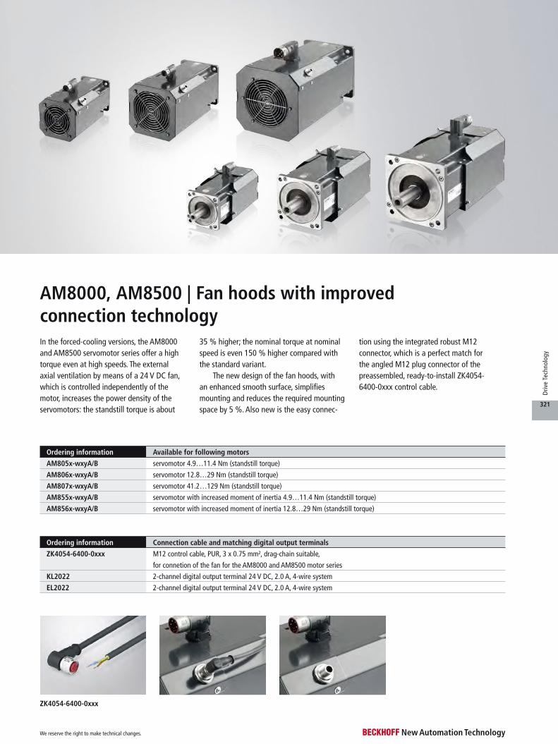
In the forced-cooling versions, the AM8000 and AM8500 servomotor series offer a high torque even at high speeds. The external axial ventilation by means of a 24 V DC fan, which is controlled independently of the motor, increases the power density of the servomotors: the standstill torque is about
35 % higher; the nominal torque at nominal speed is even 150 % higher compared with the standard variant.
The new design of the fan hoods, with an enhanced smooth surface, simplifies mounting and reduces the required mounting space by 5 %. Also new is the easy connec-
tion using the integrated robust M12 connector, which is a perfect match for the angled M12 plug connector of the preassembled, ready-to-install ZK4054- 6400-0xxx control cable.
ZK4054-6400-0xxx
Ordering information Connection cable and matching digital output terminals
ZK4054-6400-0xxx M12 control cable, PUR, 3 x 0.75 mm², drag-chain suitable,
for connetion of the fan for the AM8000 and AM8500 motor series
KL2022 2-channel digital output terminal 24 V DC, 2.0 A, 4-wire system
EL2022 2-channel digital output terminal 24 V DC, 2.0 A, 4-wire system
Ordering information Available for following motors
AM805x-wxyA/B servomotor 4.9…11.4 Nm (standstill torque)
AM806x-wxyA/B servomotor 12.8…29 Nm (standstill torque)
AM807x-wxyA/B servomotor 41.2…129 Nm (standstill torque)
AM855x-wxyA/B servomotor with increased moment of inertia 4.9…11.4 Nm (standstill torque)
AM856x-wxyA/B servomotor with increased moment of inertia 12.8…29 Nm (standstill torque)
AM8000, AM8500 | Fan hoods with improved connection technology
We reserve the right to make technical changes.
321
Driv
e Te
chno
logy
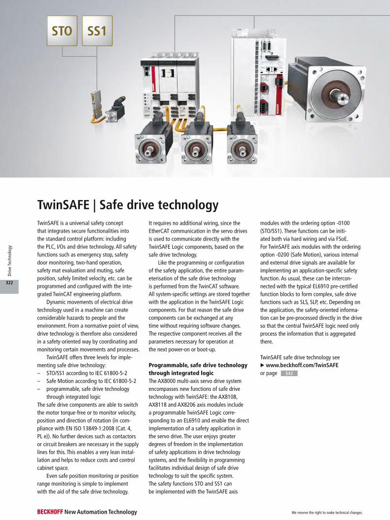
TwinSAFE | Safe drive technologyTwinSAFE is a universal safety concept that integrates secure functionalities into the standard control platform: including the PLC, I/Os and drive technology. All safety functions such as emergency stop, safety door monitoring, two-hand operation, safety mat evaluation and muting, safe position, safely limited velocity, etc. can be programmed and configured with the inte-grated TwinCAT engineering platform.
Dynamic movements of electrical drive technology used in a machine can create considerable hazards to people and the environment. From a normative point of view, drive technology is therefore also considered in a safety-oriented way by coordinating and monitoring certain movements and processes.
TwinSAFE offers three levels for imple-menting safe drive technology:– STO/SS1 according to IEC 61800-5-2– Safe Motion according to IEC 61800-5-2– programmable, safe drive technology
through integrated logicThe safe drive components are able to switch the motor torque-free or to monitor velocity, position and direction of rotation (in com-pliance with EN ISO 13849-1:2008 (Cat. 4, PL e)). No further devices such as contactors or circuit breakers are necessary in the supply lines for this. This enables a very lean instal-lation and helps to reduce costs and control cabinet space.
Even safe position monitoring or position range monitoring is simple to implement with the aid of the safe drive technology.
It requires no additional wiring, since the EtherCAT communication in the servo drives is used to communicate directly with the TwinSAFE Logic components, based on the safe drive technology.
Like the programming or configuration of the safety application, the entire param-eterisation of the safe drive technology is performed from the TwinCAT software. All system-specific settings are stored together with the application in the TwinSAFE Logic components. For that reason the safe drive components can be exchanged at any time without requiring software changes. The respective component receives all the parameters necessary for operation at the next power-on or boot-up.
Programmable, safe drive technology through integrated logicThe AX8000 multi-axis servo drive system encompasses new functions of safe drive technology with TwinSAFE: the AX8108, AX8118 and AX8206 axis modules include a programmable TwinSAFE Logic corre-sponding to an EL6910 and enable the direct implementation of a safety application in the servo drive. The user enjoys greater degrees of freedom in the implementation of safety applications in drive technology systems, and the flexibility in programming facilitates individual design of safe drive technology to suit the specific system. The safety functions STO and SS1 can be implemented with the TwinSAFE axis
modules with the ordering option -0100 (STO/SS1). These functions can be initi- ated both via hard wiring and via FSoE. For TwinSAFE axis modules with the ordering option -0200 (Safe Motion), various internal and external drive signals are available for implementing an application-specific safety function. As usual, these can be intercon-nected with the typical EL6910 pre-certified function blocks to form complex, safe drive functions such as SLS, SLP, etc. Depending on the application, the safety-oriented informa-tion can be pre-processed directly in the drive so that the central TwinSAFE logic need only process the information that is aggregated there.
TwinSAFE safe drive technology see u www.beckhoff.com/TwinSAFE or page 542
We reserve the right to make technical changes.
322
Driv
e Te
chno
logy

Ordering information TwinSAFE components for STO/SS1 according to IEC 61800-5-2
EL7047-9014 stepper motor terminal with incremental encoder, STO and vector control, 50 V DC, 5 A
EL7221-9014 EtherCAT servo terminal for OCT, with STO input, 50 V DC, Irms = 7…8 A with ZB8610
EL7211-9014 EtherCAT servo terminal for OCT, with STO input, 50 V DC, Irms = 4.5 A
EL7201-9014 EtherCAT servo terminal for OCT, with STO input, 50 V DC, Irms = 2.8 A
EP7211-9034 EtherCAT Box, industrial housing, servo box module with OCT and STO, 50 V DC, Irms = 4.5 A
EJ7211-9414 EtherCAT plug-in module, servomotor module for OCT, with STO input, 50 V DC, Irms = 4.5 A, TwinSAFE SC
EL7411-9014 BLDC motor terminal with incremental encoder and STO, 50 V DC, Irms = 4.5 A
AX5801-0200 TwinSAFE drive option card for AX5000 up to 40 A, HW 2.0: STO, SS1 (1)
AX8108-0100 single-axis module 8 A, feedback: OCT, TwinSAFE: STO/SS1, TwinSAFE Logic integrated
AX8118-0100 single-axis module 18 A, feedback: OCT, TwinSAFE: STO/SS1, TwinSAFE Logic integrated
AX8206-0100 double-axis module 2 x 6 A, feedback: OCT, TwinSAFE: STO/SS1, TwinSAFE Logic integrated
(1) only compatible with drives of the HW version 2.0 (AX5xxx-0000-020x)
(1) AX5000 up to 40 A: AX5x01-0000-020x, AX5x03-0000-020x, AX5x06-0000-020x, AX5112-0000-020x, AX5118-0000-020x, AX5125-0000-020x, AX5140-0000-020x(2) AX5000 from 60 A up to 170 A: AX5160-0000-020x, AX5172-0000-020x, AX519x-0000-020x
Ordering information TwinSAFE axis modules with integrated Logic
AX8108-0100 single-axis module 8 A, feedback: OCT, TwinSAFE: STO/SS1, TwinSAFE Logic integrated
AX8108-0200 single-axis module 8 A, feedback: OCT, TwinSAFE: Safe Motion, TwinSAFE Logic integrated
AX8118-0100 single-axis module 18 A, feedback: OCT, TwinSAFE: STO/SS1, TwinSAFE Logic integrated
AX8118-0200 single-axis module 18 A, feedback: OCT, TwinSAFE: Safe Motion, TwinSAFE Logic integrated
AX8206-0100 double-axis module 2 x 6 A, feedback: OCT, TwinSAFE: STO/SS1, TwinSAFE Logic integrated
AX8206-0200 double-axis module 2 x 6 A, feedback: OCT, TwinSAFE: Safe Motion, TwinSAFE Logic integrated
Ordering information TwinSAFE components for Safe Motion according to IEC 61800-5-2
AX5805-0000 TwinSAFE drive option card for AX5000 up to 40 A, HW 2.0: STO, SS1, SS2, SOS, SLS, SDI (1)
AX5806-0000 TwinSAFE drive option card for AX5000 from 60 A, HW 2.0: STO, SS1, SS2, SOS, SLS, SDI (2)
AX8108-0200 single-axis module 8 A, feedback: OCT, TwinSAFE: Safe Motion, TwinSAFE Logic integrated
AX8118-0200 single-axis module 18 A, feedback: OCT, TwinSAFE: Safe Motion, TwinSAFE Logic integrated
AX8206-0200 double-axis module 2 x 6 A, feedback: OCT, TwinSAFE: Safe Motion, TwinSAFE Logic integrated
We reserve the right to make technical changes.
323
Driv
e Te
chno
logy
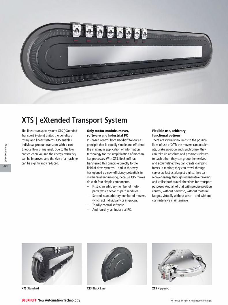
The linear transport system XTS (eXtended Transport System) unites the benefits of rotary and linear systems. XTS enables individual product transport with a con- tinuous flow of material. Due to the low construction volume the energy efficiency can be improved and the size of a machine can be significantly reduced.
Only motor module, mover, software and Industrial PCPC-based control from Beckhoff follows a principle that is equally simple and efficient: the maximum application of information technology for the simplification of mechan-ical processes. With XTS, Beckhoff has transferred this principle directly to the field of drive systems – and in this way has opened up new efficiency potentials in mechanical engineering, because XTS makes do with four simple components.– Firstly: an arbitrary number of motor
parts, which serve as path modules.– Secondly: an arbitrary number of movers,
which act individually or in groups.– Thirdly: control software.– And fourthly: an Industrial PC.
XTS | eXtended Transport SystemFlexible use, arbitrary functional optionsThere are virtually no limits to the possibi-lities of use of XTS: the movers can acceler-ate, brake, position and synchronise; they can take up absolute and positions relative to each other; they can group themselves and accumulate; they can create clamping forces in motion; they can travel through curves as fast as along straights; they can recover energy through regenerative braking and utilise both travel directions for transport purposes. And all of that with precise position control, without backlash, without material fatigue, virtually without wear – and without cost-intensive maintenance.
XTS Standard XTS Black Line XTS Hygienic
We reserve the right to make technical changes.
324
Driv
e Te
chno
logy
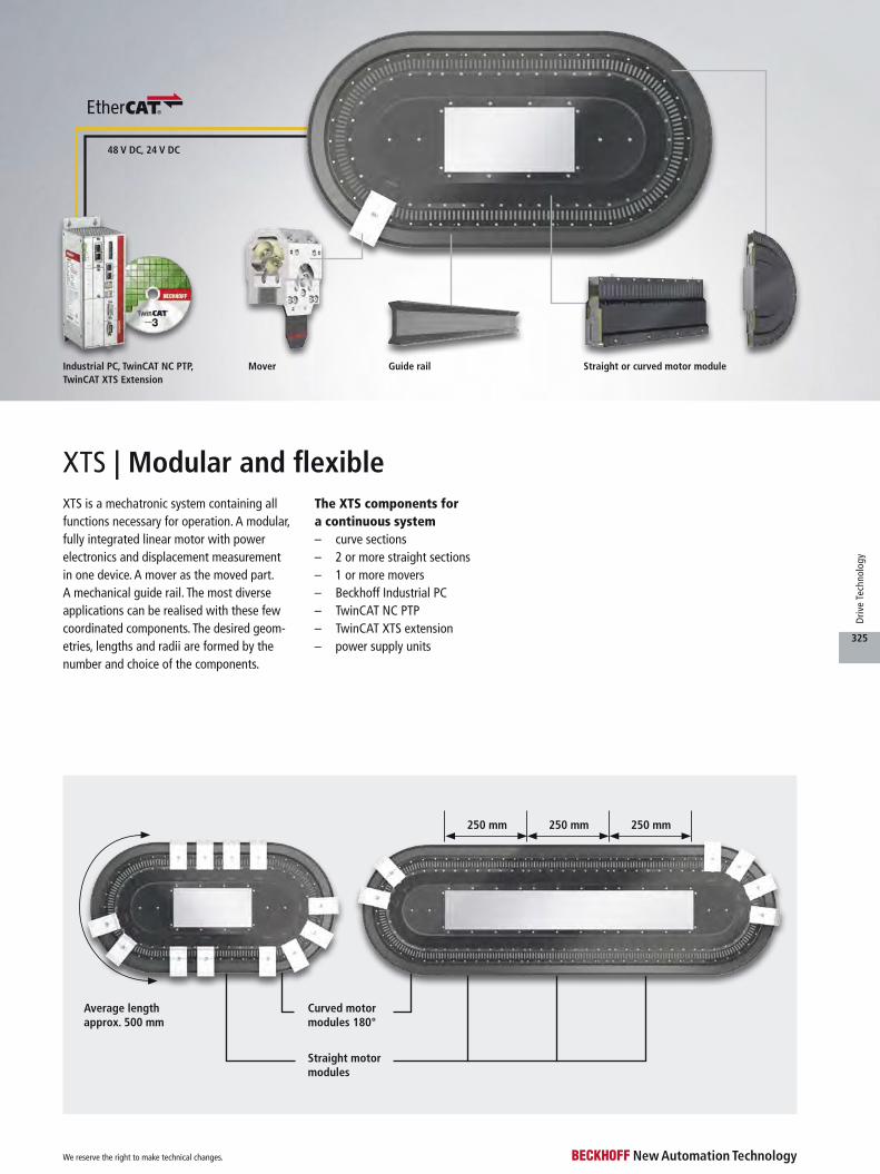
48 V DC, 24 V DC
Curved motor modules 180°
Average length approx. 500 mm
250 mm250 mm250 mm
Straight motor modules
XTS is a mechatronic system containing all functions necessary for operation. A modular, fully integrated linear motor with power electronics and displacement measurement in one device. A mover as the moved part. A mechanical guide rail. The most diverse applications can be realised with these few coordinated components. The desired geom-etries, lengths and radii are formed by the number and choice of the components.
The XTS components for a continuous system– curve sections– 2 or more straight sections– 1 or more movers– Beckhoff Industrial PC– TwinCAT NC PTP– TwinCAT XTS extension– power supply units
XTS | Modular and flexible
Mover Straight or curved motor moduleGuide railIndustrial PC, TwinCAT NC PTP, TwinCAT XTS Extension
We reserve the right to make technical changes.
325
Driv
e Te
chno
logy
F = constant
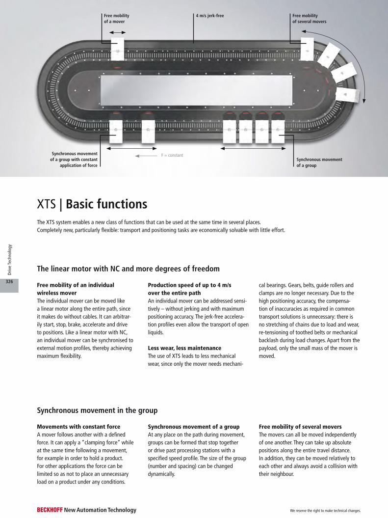
Movements with constant forceA mover follows another with a defined force. It can apply a “clamping force” while at the same time following a movement, for example in order to hold a product. For other applications the force can be limited so as not to place an unnecessary load on a product under any conditions.
Synchronous movement of a groupAt any place on the path during movement, groups can be formed that stop together or drive past processing stations with a specified speed profile. The size of the group (number and spacing) can be changed dynamically.
Free mobility of several moversThe movers can all be moved independently of one another. They can take up absolute positions along the entire travel distance. In addition, they can be moved relatively to each other and always avoid a collision with their neighbour.
XTS | Basic functionsThe XTS system enables a new class of functions that can be used at the same time in several places. Completely new, particularly flexible: transport and positioning tasks are economically solvable with little effort.
Free mobility of an individual wireless moverThe individual mover can be moved like a linear motor along the entire path, since it makes do without cables. It can arbitrar-ily start, stop, brake, accelerate and drive to positions. Like a linear motor with NC, an individual mover can be synchronised to external motion profiles, thereby achieving maximum flexibility.
Production speed of up to 4 m/s over the entire pathAn individual mover can be addressed sensi-tively – without jerking and with maximum positioning accuracy. The jerk-free accelera-tion profiles even allow the transport of open liquids.
Less wear, less maintenanceThe use of XTS leads to less mechanical wear, since only the mover needs mechani-
cal bearings. Gears, belts, guide rollers and clamps are no longer necessary. Due to the high positioning accuracy, the compensa-tion of inaccuracies as required in common transport solutions is unnecessary: there is no stretching of chains due to load and wear, re-tensioning of toothed belts or mechanical backlash during load changes. Apart from the payload, only the small mass of the mover is moved.
The linear motor with NC and more degrees of freedom
Synchronous movement in the group
Free mobility of a mover
4 m/s jerk-free
Synchronous movement of a group with constant
application of forceSynchronous movement of a group
Free mobility of several movers
We reserve the right to make technical changes.
326
Driv
e Te
chno
logy

Push product, adapt product spacing, reduce or increase product speed
Clamp and move product
Use of the basic functions
Interruption-free production flow
From the combination of the basic functions, product flows can be kept constantly in motion with XTS. Since the movers in the XTS operate independently of each other, it is possible to stop and process individual objects without having to interrupt the entire process. Viewed from the outside the production flow is maintained.
Push product, adapt product spacing, reduce or increase product speedThe movers of the XTS system can always run with the flow of product. No return trip or return stroke is necessary. The transported material can be accumulated and grouped during the movement via the dynamic buffering.
Clamp and move productThrough the combination of the synchronous movement of a group and the application of a constant force, a product can be clamped and moved in a clamped condition. Move-ment is controlled at all times and at all places on the transport path.
We reserve the right to make technical changes.
327
Driv
e Te
chno
logy

XTS | Complex functions
> 10 m
Arbitrary number of movers
Arbitrary system length
Due to the mechatronic concept, XTS com-bines functions and characteristics that are required for the dynamic transport of goods of all kinds. Apart from the basic functions of the movers, the complex functions of XTS enable the gentle control of an endless prod-uct flow.
Arbitrary number of moversThere are no system limits for the number of movers; consequently the number can be optimally adapted to the application. In prac-tice the number is limited only by the avail-able computing power of the PC.
Unrestricted curve functionThe entire travel path becomes the utilisable path, since the outward and return path and also the curve segments are available for the transport and processing of materials. This maximum utilisation of the machine volume results in very compact application solutions, which enable completely new machine con-cepts.
Arbitrary system lengthThere are no restrictions on the total length of the path, so that 10 m and much more are technically possible. The system consists of individual modules, which when combined with one another create both small, compact solutions and metre-long transport paths. Straight sections are made up of 250 mm modules which can be made endless by the use of curved segments. A motor cable has to be attached at least every three metres. The electrical connection between the mod-ules is automatically made when assembling. The guide rail system offers lengths of up to 2.5 m.
Lower mass, increased safetySmall masses lead to a lower hazard poten-tial, because unlike XTS, a conveyor chain is kept in motion by a central drive unit. The total acting force corresponds to the sum of all necessary individual forces over the entire length. In the case of an error, a mechanical malfunction or a manual
intervention in the process, this force acts on one place. With XTS this risk can be signifi- cantly minimised and safety can be increased, since in most cases only the parameterised force of a mover acts. Hence, even in the case of a collision with an obstacle, only the mass of a mover with its payload acts.
Dynamic buffering: accumulation of movers and products
We reserve the right to make technical changes.
328
Driv
e Te
chno
logy

Integrated collision avoidance
Unrestricted curve function
F = constant
Group movement in the product flow
Grouping of movers in the product flow
High-power dynamics, but no unrestrained forceThe fast signal processing and the large bandwidth of EtherCAT enable the best dynamic characteristics. Together with large peak forces, high acceleration is available to the application. Position lag monitoring avoids damage to the product in case of mechanical malfunctions. In addition, force limitation and jerk reduction allow the opti-mal handling of the product at all times at different points in the production. For exam-ple, the parameters can be adapted according to the filling level while moving.
Absolutely precise configurationThe arbitrary number of movers, the modular path guidance, the individual controllability of each individual mover and the simple inte-grability into existing machines and plants ensure a precisely matching solution with which the production efficiency of a machine can be further optimised.
Fast, flexible format adaptationA change of format when changing products or, for example, when the filling quantity changes can be carried out without stopping production: the modifications can be realised
by changing the software parameters and empirical values can also be retrieved at any time in the form of a stored parameter set. The parameters can be exchanged between applications of the same type.
Control of a continuous product flow
We reserve the right to make technical changes.
329
Driv
e Te
chno
logy
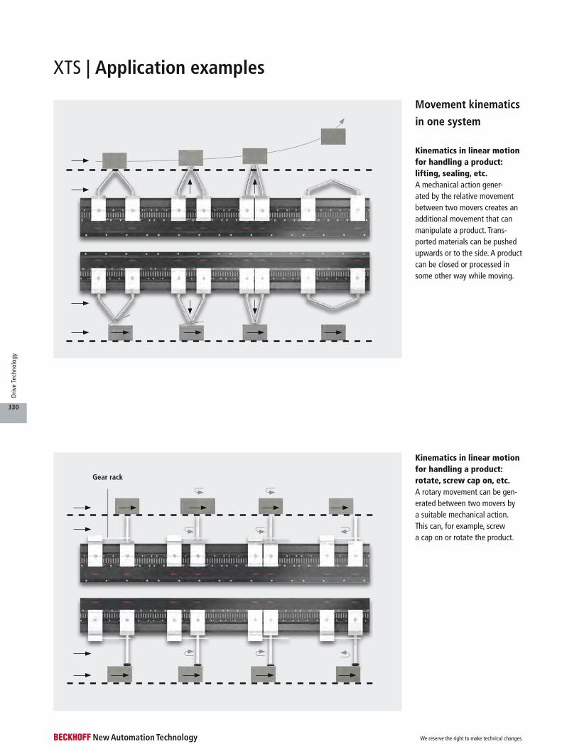
Movement kinematics
in one system
Kinematics in linear motion for handling a product: rotate, screw cap on, etc.A rotary movement can be gen-erated between two movers by a suitable mechanical action. This can, for example, screw a cap on or rotate the product.
Kinematics in linear motion for handling a product: lifting, sealing, etc.A mechanical action gener-ated by the relative movement between two movers creates an additional movement that can manipulate a product. Trans-ported materials can be pushed upwards or to the side. A product can be closed or processed in some other way while moving.
Gear rack
XTS | Application examples
We reserve the right to make technical changes.
330
Driv
e Te
chno
logy

Conveyor
Movement kinematics in two systems
Transport and discharge productA package or a case is transported on a surface. The pack-age is to be deposited at a station. The surface is tilted to the side and the package slides off. Four movers on two paths move the tilting surface with the transported material. A change in the spacing of the movers with respect to each other generates a mechanical action that tilts the surface. The transported material can be pre-vented from sliding off when driving through curves by an inclined position and can be specifically deposited at another place while driving or after stopping.
Travelling manipulator
With circulating kinematics the transported product can be influenced in X and Y directions. With two XTS systems arranged in parallel, the manipulator is synchro-nised to the product and shifts it on the belt at full speed. The product can even be slightly rotated by using appro-priate kinematics.
Grouping system
Used as a grouping system, the XTS can easily combine products arriving on multiple conveyor belts into prede-fined and easily changed groups and move them to the next station.
The plant can adapt to the product width, stack height and number of stacks without any manual inter-vention. The distance between the movers and also the motion profile are changed by parameters in the software. This can even be done during operation without a stand-still.
Mover
XTS 2XTS 1
Mover
Possiblemovements
Kinematics
Product
Product
We reserve the right to make technical changes.
331
Driv
e Te
chno
logy
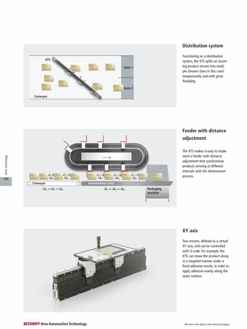
Packagingmachine
∆L1 ≠ ∆L2 ≠ ∆Ln ∆L1 = ∆L2 = ∆Ln
∆L1 ∆L2
Conveyor Intermediate plate
∆L1 ∆L2 ∆Ln
Gate 1
Gate 2
Conveyor
XTS
Feeder with distance
adjustment
The XTS makes it easy to imple-ment a feeder with distanceadjustment that synchronises products arriving at differentintervals with the downstream process.
XY axis
Two movers, defined as a virtual XY axis, and can be controlled with G-code. For example, the XTS can move the product along in a targeted manner under a fixed adhesive nozzle, in order to apply adhesive evenly along the outer contour.
Functioning as a distribution system, the XTS splits an incom-ing product stream into multi-ple streams (two in this case) inexpensively and with great flexibility.
Distribution system
We reserve the right to make technical changes.
332
Driv
e Te
chno
logy
XTS | Trajectories
Square
Circle, negative curve Straight, not closed
RectangleS-shape
Circle, positive curve
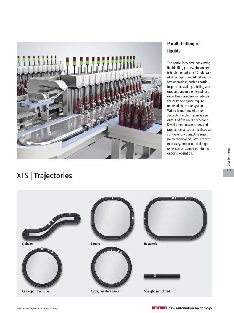
Parallel filling of
liquids
The particularly time-consuming liquid filling process shown here is implemented as a 15-fold par-allel configuration. All inherently fast operations, such as bottle inspection, sealing, labeling and grouping are implemented just once. This considerably reduces the costs and space require-ments of the entire system. With a filling time of three seconds, the plant achieves an output of five units per second. Dwell times, accelerations and product distances are realised as software functions. As a result, no mechanical adjustments are necessary, and product change-overs can be carried out during ongoing operation.
We reserve the right to make technical changes.
333
Driv
e Te
chno
logy
See page
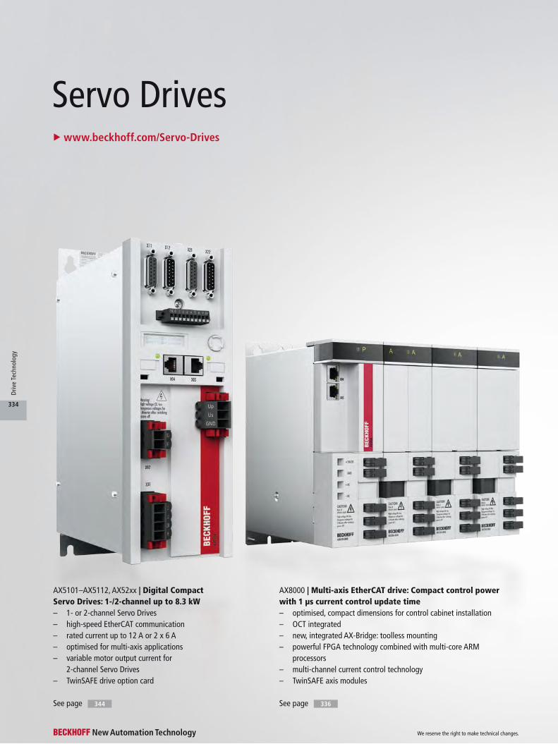
AX5101–AX5112, AX52xx | Digital Compact Servo Drives: 1-/2-channel up to 8.3 kW– 1- or 2-channel Servo Drives– high-speed EtherCAT communication– rated current up to 12 A or 2 x 6 A– optimised for multi-axis applications– variable motor output current for
2-channel Servo Drives– TwinSAFE drive option card
See page
AX8000 | Multi-axis EtherCAT drive: Compact control power with 1 µs current control update time– optimised, compact dimensions for control cabinet installation– OCT integrated– new, integrated AX-Bridge: toolless mounting– powerful FPGA technology combined with multi-core ARM
processors– multi-channel current control technology– TwinSAFE axis modules
Servo Drivesu www.beckhoff.com/Servo-Drives
344 336
We reserve the right to make technical changes.
334
Driv
e Te
chno
logy

See page 3922
AX5118–AX5140 | Digital Compact Servo Drives: 1-channel up to 28 kW– high-speed EtherCAT communication– rated current: 18/25/40 A– flexible motor type selection– TwinSAFE drive option card
AX5160–AX5193 | Digital Compact Servo Drives: 1-channel up to 118 kW– high-speed EtherCAT communication– rated current: 60/72/90/110/143/170 A– high performance with small dimensions– flexible motor type selection– TwinSAFE drive option card
See pageSee page 344 344
EJ7211-xxxx | Servomotor modules with OCT, 4.5 A– seamless integration within
EtherCAT I/O system– direct motor connection with OCT– EJ7211-9414 enables implementation
of the STO (Safe Torque Off) safety function
– vector control for highly dynamic positioning tasks
– designed for use with AM8100
See pageSee page
228
311
EL72x1-9014 | Compact servo drive in EtherCAT Terminals– seamless integration within
EtherCAT I/O system– various performance classes
between 2.8 and 8 A– direct motor connection with OCT– enables implementation of the STO
(Safe Torque Off) safety function– vector control for highly
dynamic positioning tasks– designed for use with AM8100
EP7211-9034 | Servomotor box with OCT and STO, 4.5 A– seamless integration within
EtherCAT I/O system– direct motor connection with OCT– enables implementation of the STO
(Safe Torque Off) safety function– vector control for highly
dynamic positioning tasks– designed for use with AM8100
2
2
We reserve the right to make technical changes.
335
Driv
e Te
chno
logy

Connection for external brake resistor
TwinSAFE
Power supply for 24 V DC control voltage
Status display
Axis modules
AX-Bridge connects 24 V DC, EtherCAT, DC-Link
One Cable Technology (OCT) motor circuit
4 digital inputs, e.g. safety,
capture, enable
EtherCAT interface
Measuring points for test prods
Power supply module
Power supply 100…240 V AC (1~), 200…480 V AC (3~)
Alignment for simple mounting
AX8000 | Multi-axis servo systemu www.beckhoff.com/AX8000
We reserve the right to make technical changes.
336
Driv
e Te
chno
logy
Technical data AX8000
Bus system EtherCAT
Drive profile CiA402 according to IEC 61800-7-201 (CoE)
Rated supply voltage 100…480 V AC, 50/60 Hz
DC-Link voltage 140…875 V DC
Current control 1 µs update time, 16 µs cycle time
Design form modular system with 60 or 90 mm wide elements
Protection class IP 20
Operating temperature 0…+55 °C (see documentation)
Approvals CE, cULus
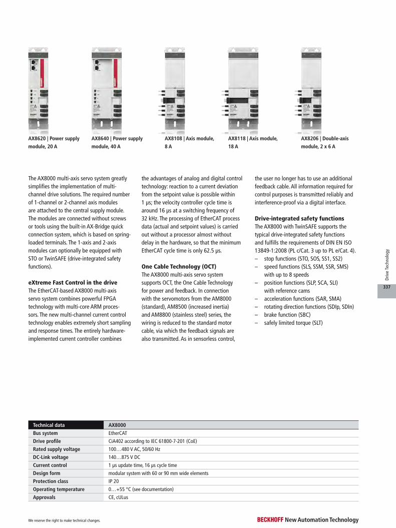
AX8620 | Power supply
module, 20 A
AX8640 | Power supply
module, 40 A
AX8108 | Axis module,
8 A
AX8118 | Axis module,
18 A
AX8206 | Double-axis
module, 2 x 6 A
The AX8000 multi-axis servo system greatly simplifies the implementation of multi-channel drive solutions. The required number of 1-channel or 2-channel axis modules are attached to the central supply module. The modules are connected without screws or tools using the built-in AX-Bridge quick connection system, which is based on spring-loaded terminals. The 1-axis and 2-axis modules can optionally be equipped with STO or TwinSAFE (drive-integrated safety functions).
eXtreme Fast Control in the driveThe EtherCAT-based AX8000 multi-axis servo system combines powerful FPGA technology with multi-core ARM proces-sors. The new multi-channel current control technology enables extremely short sampling and response times. The entirely hardware-implemented current controller combines
the advantages of analog and digital control technology: reaction to a current deviation from the setpoint value is possible within 1 µs; the velocity controller cycle time is around 16 µs at a switching frequency of 32 kHz. The processing of EtherCAT process data (actual and setpoint values) is carried out without a processor almost without delay in the hardware, so that the minimum EtherCAT cycle time is only 62.5 µs.
One Cable Technology (OCT)The AX8000 multi-axis servo system supports OCT, the One Cable Technology for power and feedback. In connection with the servomotors from the AM8000 (standard), AM8500 (increased inertia) and AM8800 (stainless steel) series, the wiring is reduced to the standard motor cable, via which the feedback signals are also transmitted. As in sensorless control,
the user no longer has to use an additional feedback cable. All information required for control purposes is transmitted reliably and interference-proof via a digital interface.
Drive-integrated safety functionsThe AX8000 with TwinSAFE supports the typical drive-integrated safety functions and fulfills the requirements of DIN EN ISO 13849-1:2008 (PL c/Cat. 3 up to PL e/Cat. 4).– stop functions (STO, SOS, SS1, SS2)– speed functions (SLS, SSM, SSR, SMS)
with up to 8 speeds– position functions (SLP, SCA, SLI)
with reference cams– acceleration functions (SAR, SMA)– rotating direction functions (SDIp, SDIn)– brake function (SBC)– safely limited torque (SLT)
We reserve the right to make technical changes.
337
Driv
e Te
chno
logy

AX8000
A power supply module gener-ates the DC-Link voltage (DC) for the supply of the axis modules and the option mod-ules from the mains voltage. It already contains a mains filter, for which the drive is tested and certified in accor-
dance with EN 61800-3 for Category C3 use.
Any regenerative energy produced, e.g. through strong braking of the motors, can be converted into heat either via the internal brake resistor or via the combination of built-in brake
chopper and external brake resistor. Alternatively, the energy can be buffered in the AX8810 capacitor module.
AX8000 supply modules can be used on 1- and 3-phase low-voltage mains supplies.
– 1-phase mains supplies 100…240 V AC, 50/60 Hz
– 3-phase mains supplies 200…480 V AC, 50/60 Hz
A separate 24 V DC power sup-ply is required in each case.
AX8620, AX8640 | Power supply modules
Technical data AX8620-0000-0000 AX8640-0000-0000
Rated supply voltage 1 x 100…240 V AC
3 x 200…480 V AC
Rated input current at 40 °C 1~: 10.0 A AC
3~: 17.5 A AC
3~: 35 A AC
Rated output current 1~: 5 A DC without mains choke/7 A DC with mains choke
3~: 20 A DC
3~: 40.0 A DC
Rated output 1~: 2.0 kW
3~: 10.7 kW
3~: 21.4 kW
DC-Link voltage max. 875 V DC
DC-Link capacitance 405 µF 625 µF
Max. braking power (internal/external) 21.8 kW/21.8 kW 43.6 kW/40.1 kW
Further information www.beckhoff.com/AX8620 www.beckhoff.com/AX8640
We reserve the right to make technical changes.
338
Driv
e Te
chno
logy

AX8000
Technical data AX8108 AX8118 AX8206
Rated current 1 x 8 A 1 x 18 A 2 x 6 A
DC-Link voltage max. 875 V DC
DC-Link capacitance 135 µF 405 µF 135 µF
Number of channels 1 1 2
Min. rated channel current
at full current resolution
1 A 5 A 1 A
Peak output current* 20 A 40 A 14 A | 20 A
Further information www.beckhoff.com/AX81xx www.beckhoff.com/AX81xx www.beckhoff.com/AX82xx
Ordering information Axis module 1 x 8 A Axis module 1 x 18 A Axis module 2 x 6 A
Without TwinSAFE AX8108-0000-0000 AX8118-0000-0000 AX8206-0000-0000
STO/SS1 AX8108-0100-0000 AX8118-0100-0000 AX8206-0100-0000
Safe Motion AX8108-0200-0000 AX8118-0200-0000 AX8206-0200-0000
*rating for 560 V DC
AX81xx, AX8206 | Axis modulesAn axis module contains the DC-Link and the inverter for supplying the motor. Depending on the required number of axes, the axis modules are attached to the supply module to form the multi-axis servo system. Axis modules with different ratings can be combined in order to enable an optimised design of the individual axes.
Supporting a wide supply voltage range from 100 to 480 V AC, the axis modules can be operated without limitation with any of the supply modules. This flexibility simplifies the
implementation of machine configurations for any type of mains supply. The electrical con-nection is established without tools via the already integrated AX-Bridge: it automatically con-nects DC-Link, 24 V DC control voltage and communication via EtherCAT between the linked modules. The DC-Link connection enables the exchange of energy during acceleration and braking procedures, where the regenera-tive brake energy is primarily stored in the common DC-Link. If the energy exceeds the DC-Link capacitance, utilize the
brake resistor of the AX881x capacitor modul to suppress the DC-Link voltage. The AX8000 multi-axis servo drive system encompasses new functions of safe drive technology with TwinSAFE: the AX8108, AX8118 and AX8206 axis modules include a programmable TwinSAFE Logic corresponding to an EL6910 and enable the direct implementation of a safety application in the servo drive. The user enjoys greater degrees of freedom in the implementa-tion of safety applications in drive technology systems, and
the flexibility in programming facilitates individual design of safe drive technology to suit the specific system. The safety functions STO and SS1 can be implemented with the TwinSAFE axis modules with the ordering option -0100 (STO/SS1). These functions can be initiated both via hard wiring and via FSoE. For TwinSAFE axis modules with the ordering option -0200 (Safe Motion), various internal and external drive signals are avail-able for implementing an appli-cation-specific safety function.
We reserve the right to make technical changes.
339
Driv
e Te
chno
logy
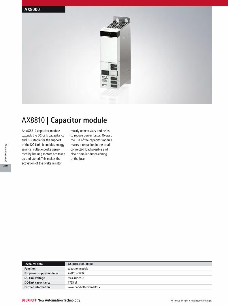
An AX8810 capacitor module extends the DC-Link capacitance and is suitable for the support of the DC-Link. It enables energy savings: voltage peaks gener-ated by braking motors are taken up and stored. This makes the activation of the brake resistor
mostly unnecessary and helps to reduce power losses. Overall, the use of the capacitor module makes a reduction in the total connected load possible and also a smaller dimensioning of the fuse.
AX8810 | Capacitor module
AX8000
Technical data AX8810-0000-0000
Function capacitor module
For power supply modules AX86xx-0000
DC-Link voltage max. 875 V DC
DC-Link capacitance 1755 µF
Further information www.beckhoff.com/AX881x
We reserve the right to make technical changes.
340
Driv
e Te
chno
logy
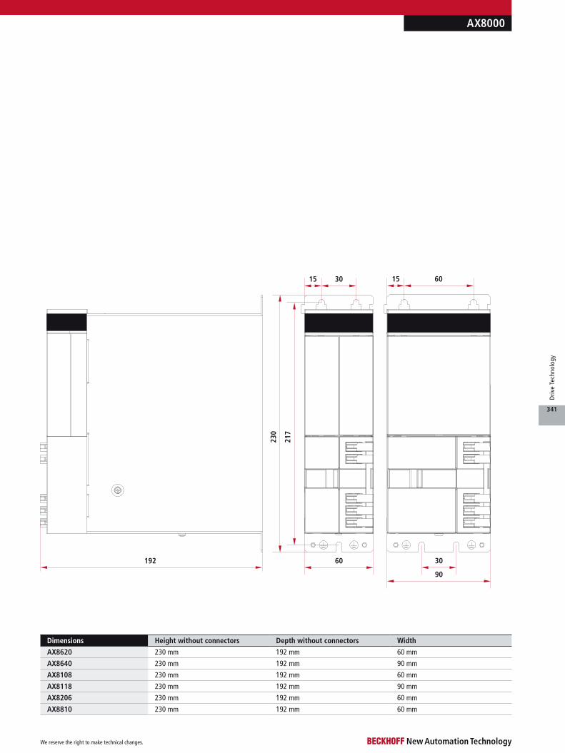
Dimensions Height without connectors Depth without connectors Width
AX8620 230 mm 192 mm 60 mm
AX8640 230 mm 192 mm 90 mm
AX8108 230 mm 192 mm 60 mm
AX8118 230 mm 192 mm 90 mm
AX8206 230 mm 192 mm 60 mm
AX8810 230 mm 192 mm 60 mm
3015 6015
192 30
90
60
230
217
AX8000
We reserve the right to make technical changes.
341
Driv
e Te
chno
logy

Ordering information Motor cable with 1.5 mm² wire gauge, fixed installation
ZK4800-8003-xxxx Cables for fixed installation,
min. bending radius = 61 mm (5 x OD),
(4 x 1.5 mm² + (2 x 0.75 mm²) + (2 x AWG22)).
The cable is UL and CSA listed.
ZK4800-8003-0050 example for 5 m length
ZK4501-8003-xxxx extension cable
Ordering information Motor cable with 1.5 mm² wire gauge, highly flexible for drag-chain use
ZK4800-8023-xxxx Highly flexible, drag-chain suitable cable with 5 million bending cycles, max. 240 m/min, max. 30 m/s²,
min. bending radius = 89 mm (7 x OD), max. drag-chain length horizontal 20 m, vertical 5 m,
(4 x 1.5 mm² + (2 x 0.75 mm²) + (2 x AWG22)).
The cable is UL and CSA listed.
ZK4800-8023-0050 example for 5 m length
ZK4501-8023-xxxx extension cable
Ordering information Motor cable with 2.5 mm² wire gauge, fixed installation
ZK4800-8004-xxxx Cables for fixed installation,
min. bending radius = 69 mm (5 x OD),
(4 x 2.5 mm² + (2 x 1 mm²) + (2 x AWG22)).
The cable is UL and CSA listed.
ZK4800-8004-0050 example for 5 m length
ZK4501-8004-xxxx extension cable
Ordering information Motor cable with 2.5 mm² wire gauge, highly flexible for drag-chain use
ZK4800-8024-xxxx Highly flexible, drag-chain suitable cable with 5 million bending cycles, max. 240 m/min, max. 30 m/s²,
min. bending radius = 97 mm (7 x OD), max. drag-chain length horizontal 20 m, vertical 5 m,
(4 x 2.5 mm² + (2 x 1 mm²) + (2 x AWG22)).
The cable is UL and CSA listed.
ZK4800-8024-0050 example for 5 m length
ZK4501-8024-xxxx extension cable
Motor cables 1 mm² for motors with itec® plug at AX8108 and AX8206
Motor cables 1.5 mm² for motors with M23 speedtec® at AX8108 and AX8206
Motor cables 2.5 mm² for motors with M23 speedtec® plug at AX8118
Ordering information Motor cable with 1 mm² wire gauge, highly flexible for drag-chain use
ZK4800-8022-xxxx Highly flexible, drag-chain suitable cable with 5 million bending cycles, max. 240 m/min, max. 30 m/s²,
min. bending radius = 81 mm (7 x OD), max. drag-chain length horizontal 20 m, vertical 5 m,
(4 x 1 mm² + (2 x 0.75 mm²) + (2 x AWG22)).
The cable is UL and CSA listed.
ZK4800-8022-0050 example for 5 m length
ZK4501-8022-xxxx extension cable
For maximum cable lengths and further specifications see current documentation under u www.beckhoff.com/documentation. Torsion-resistant variants for robotic applications are available in the following wire gauges: 1 mm², 1.5 mm², 2.5 mm².
AX8000 cables
Motor supply cables for AX8000 Servo Drives at AM8xxx
We reserve the right to make technical changes.
342
Driv
e Te
chno
logy
AX8000 accessories
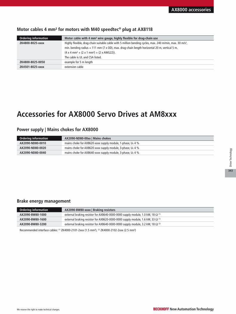
Brake energy management
Recommended interface cables: (1) ZK4000-2101-2xxx (1.5 mm²), (2) ZK4000-2102-2xxx (2.5 mm²)
Ordering information AX2090-BW80-xxxx | Braking resistors
AX2090-BW80-1000 external braking resistor for AX8640-0000-0000 supply module, 1.0 kW, 18 Ω (1)
AX2090-BW80-1600 external braking resistor for AX8620-0000-0000 supply module, 1.6 kW, 33 Ω (1)
AX2090-BW80-3200 external braking resistor for AX8640-0000-0000 supply module, 3.2 kW, 18 Ω (2)
Motor cables 4 mm² for motors with M40 speedtec® plug at AX8118
Power supply | Mains chokes for AX8000
Ordering information AX2090-ND80-00xx | Mains chokes
AX2090-ND80-0010 mains choke for AX8620-xxxx supply module, 1-phase, UK 4 %
AX2090-ND80-0020 mains choke for AX8620-xxxx supply module, 3-phase, UK 4 %
AX2090-ND80-0040 mains choke for AX8640-xxxx supply module, 3-phase, UK 4 %
Accessories for AX8000 Servo Drives at AM8xxx
Ordering information Motor cable with 4 mm² wire gauge, highly flexible for drag-chain use
ZK4800-8025-xxxx Highly flexible, drag-chain suitable cable with 5 million bending cycles, max. 240 m/min, max. 30 m/s²,
min. bending radius = 111 mm (7 x OD), max. drag-chain length horizontal 20 m, vertical 5 m,
(4 x 4 mm² + (2 x 1 mm²) + (2 x AWG22)).
The cable is UL and CSA listed.
ZK4800-8025-0050 example for 5 m length
ZK4501-8025-xxxx extension cable
We reserve the right to make technical changes.
343
Driv
e Te
chno
logy

Motor feedback: Sin/Cos 1 VPP, EnDat, Hiperface, BiSS
Motor feedback: resolver
DC-Link system or external braking resistor
24 V DC control and braking voltage
8 digital I/Os, e.g. enable, limit switch, capture input, error message
Motor outputs
Brake control, motor temperature monitoring, OCT
EtherCAT system bus
Power supply 100 V AC -10 %… 480 V AC +10 %
Optional slot for interface boards, e.g. additional feedback
Optional slot for TwinSAFE safety cards
Motor feedback (only for AX52xx 2-axis module): Sin/Cos
1 VPP, EnDat, Hiperface, BiSS
Motor feedback (only for AX52xx 2-axis module): resolver
Status display, e.g. axis identifier
or a diagnostic messageNavigation buttons
Operating material identification
AX5000 | Digital Compact Servo Drivesu www.beckhoff.com/AX5000
We reserve the right to make technical changes.
344
Driv
e Te
chno
logy

Technical data AX5000
Bus system EtherCAT
Drive profile SERCOS™ profile for servo drives according to IEC 61800 7 204 (SoE)
Rated supply voltage 100…480 V AC, 50/60 Hz
DC-Link voltage max. 875 V DC
Current control 62.5 µs
Design form compact Servo Drive in 1- and 2-channel models, multi-axis systems with AX-Bridge
Protection class IP 20
Operating temperature AX5x01…AX5140: 0…50 °C, AX5160…AX5193: 0…40 °C
Approvals CE, cULus
AX5101–AX5112 |
1-channel, up to 12 A
high-speed control technology with a current control cycle of down to 62.5 µs, the AX5000 drives support fast and highly dynamic posi-tioning tasks. The drives utilise EtherCAT as a high-performance communication system, providing an ideal interface with PC-based control technology while supporting coupling
The EtherCAT drivesThe AX5000 Servo Drive product line from Beckhoff sets new standards in drive per-formance. The AX5000 series is available in single- or multi-channel form and is optimised for exceptional functionality and cost-effectiveness. Featuring integrated,
with other fieldbus systems. The 2-channel Servo Drives with variable motor output cur-rent optimise the packaging density and the cost per drive channel. The compact design and simple and safe installation through the “AX-Bridge” quick connection system signifi-cantly simplify control cabinet assembly.
AX52xx | 2-chan nel,
up to 2 x 6 A
AX5118–AX5140 |
1-channel, 18/25/40 A
AX5160, AX5172 |
1-channel, 60/72 A
AX5190, AX5191 |
1-channel, 90/110 A
AX5192, AX5193 |
1-channel, 143/170 A
– fast control algorithms– current control: min. 62.5 µs– speed control: min. 62.5 µs– position control: min. 62.5 µs
– variably adjustable current and speed filters – high-speed EtherCAT system communication– 1- or 2-channel Servo Drive
– optimised for multi-axis applications– variable motor output current
in 2-channel drives– active DC-Link and brake energy management
via AX-Bridge– variable motor interface with
– multi-feedback interface– flexible motor type selection– scalable, wide range motor current measurement
– OCT (One Cable Technology)– electronic identification plate
– high-speed capture inputs– eight programmable digital I/Os, two with timestamp
– mains connection– wide voltage range 100…480 V AC– integrated mains filter
– integration of safety functions (optional)– STO, SS1– TwinSAFE: intelligent safety functions for Motion Control
with AX58xx– compact design for simple control cabinet installation
(300 mm depth)– AX-Bridge – the quick connection system for
power supply, DC-Link and control voltage– variable cooling concept (fanless, forced cooling)
Technical highlights
We reserve the right to make technical changes.
345
Driv
e Te
chno
logy
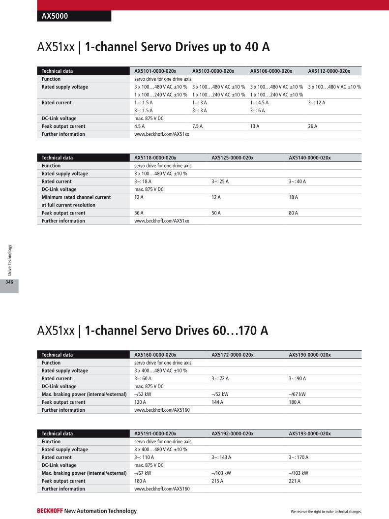
Technical data AX5191-0000-020x AX5192-0000-020x AX5193-0000-020x
Function servo drive for one drive axis
Rated supply voltage 3 x 400…480 V AC ±10 %
Rated current 3~: 110 A 3~: 143 A 3~: 170 A
DC-Link voltage max. 875 V DC
Max. braking power (internal/external) –/67 kW –/103 kW –/103 kW
Peak output current 180 A 215 A 221 A
Further information www.beckhoff.com/AX5160
Technical data AX5160-0000-020x AX5172-0000-020x AX5190-0000-020x
Function servo drive for one drive axis
Rated supply voltage 3 x 400…480 V AC ±10 %
Rated current 3~: 60 A 3~: 72 A 3~: 90 A
DC-Link voltage max. 875 V DC
Max. braking power (internal/external) –/52 kW –/52 kW –/67 kW
Peak output current 120 A 144 A 180 A
Further information www.beckhoff.com/AX5160
Technical data AX5118-0000-020x AX5125-0000-020x AX5140-0000-020x
Function servo drive for one drive axis
Rated supply voltage 3 x 100…480 V AC ±10 %
Rated current 3~: 18 A 3~: 25 A 3~: 40 A
DC-Link voltage max. 875 V DC
Minimum rated channel current
at full current resolution
12 A 12 A 18 A
Peak output current 36 A 50 A 80 A
Further information www.beckhoff.com/AX51xx
Technical data AX5101-0000-020x AX5103-0000-020x AX5106-0000-020x AX5112-0000-020x
Function servo drive for one drive axis
Rated supply voltage 3 x 100…480 V AC ±10 %
1 x 100…240 V AC ±10 %
3 x 100…480 V AC ±10 %
1 x 100…240 V AC ±10 %
3 x 100…480 V AC ±10 %
1 x 100…240 V AC ±10 %
3 x 100…480 V AC ±10 %
Rated current 1~: 1.5 A
3~: 1.5 A
1~: 3 A
3~: 3 A
1~: 4.5 A
3~: 6 A
3~: 12 A
DC-Link voltage max. 875 V DC
Peak output current 4.5 A 7.5 A 13 A 26 A
Further information www.beckhoff.com/AX51xx
AX5000
AX51xx | 1-channel Servo Drives up to 40 A
AX51xx | 1-channel Servo Drives 60…170 A
We reserve the right to make technical changes.
346
Driv
e Te
chno
logy

Technical data AX5201-0000-020x AX5203-0000-020x AX5206-0000-020x
Function servo drive for two drive axes with flexible distribution of the total device current
Rated supply voltage 3 x 100…480 V AC ±10 %
1 x 100…240 V AC ±10 %
Rated current 1~: 2 x 1.5 A
3~: 2 x 1.5 A
1~: 2 x 3 A
3~: 2 x 3 A
1~: 2 x 4.5 A
3~: 2 x 6 A
DC-Link voltage max. 875 V DC
Peak output current 2 x 5 A 2 x 10 A 2 x 13 A
Further information www.beckhoff.com/AX52xx
AX5000
Dimensions Height without connectors Width Depth without connectors
AX5101 274 mm 92 mm 232 mm
AX5103 274 mm 92 mm 232 mm
AX5106 274 mm 92 mm 232 mm
AX5112 274 mm 92 mm 232 mm
AX5118 274 mm 185 mm 232 mm
AX5125 274 mm 185 mm 232 mm
AX5140 274 mm 185 mm 232 mm
AX5201 274 mm 92 mm 232 mm
AX5203 274 mm 92 mm 232 mm
AX5206 274 mm 92 mm 232 mm
AX5160 345 mm 190 mm 259 mm
AX5172 345 mm 190 mm 259 mm
AX5190 540 mm 280 mm 253 mm
AX5191 540 mm 280 mm 253 mm
AX5192 540 mm 280 mm 332 mm
AX5193 540 mm 280 mm 332 mm
Typical combinations
AX5000
Mains choke Mains filter Braking resistor
(x = 3 or 6)
AX5160 AX2090-ND50-0060 integrated (C3 up to 25 m) AX2090-BW52-x000
AX5172 AX2090-ND50-0072 integrated (C3 up to 25 m) AX2090-BW52-x000
AX5190 AX2090-ND50-0090 AX2090-NF50-0100 AX2090-BW53-x000
AX5191 AX2090-ND50-0110 AX2090-NF50-0150 AX2090-BW53-x000
AX5192 AX2090-ND50-0143 AX2090-NF50-0150 AX2090-BW54-x000
AX5193 AX2090-ND50-0170 AX2090-NF50-0180 AX2090-BW54-x000
Braking resistor: x = power in kW
AX52xx | 2-channel Servo Drives
We reserve the right to make technical changes.
347
Driv
e Te
chno
logy

Significant hazards to persons arise from the dynamic movements of the electrical drive equipment of machines. With the AX58xx TwinSAFE drive option cards numerous safety functions can be easily implemented by the user. No further circuits are necessary for this, such as circuit breakers or contactors in the supply lines or special external encoder sys-tems. Optional cards that are certified accord-ing to DIN EN ISO 13849-1:2008 (Cat. 4, PL e) and IEC 61508:2010 (SIL 3) are available for different safety categories:
AX5801 | Personal protection against inadvertent restart of the drive axis (STO/SS1):– Safe Torque Off (STO) according to
IEC 61800-5-2– control through safe 24 V DC outputs– mains voltage and motor line remain
connected
AX5805, AX5806 | Safe Motion according to IEC 61800-5-2. Control is performed via EtherCAT; no further wiring is required:
– stop functions (STO, SOS, SS1, SS2)– speed functions (SLS, SSM, SSR, SMS)
with up to 8 speeds– position functions (SLP, SCA, SLI) with reference cams– acceleration functions (SAR, SMA)– rotating direction functions (SDIp, SDIn)
AX58xx | TwinSAFE drive options cards
B
C
The AX5000 Servo Drive series supports a large number of feedback interfaces via the multi-feedback interface: – resolver (2-, 4-, 6- or 8-pole)– SinCos encoder 1 VPP
– single- and multi-turn encoder EnDat– single- and multi-turn encoder EnDat 2.2– single- and multi-turn encoder
Hiperface 1 VPP
– single- and multi-turn encoder BiSS 1 VPP
– single- and multi-turn encoder 1 VPP
From hardware revision 2 onwards, OCT (One Cable Technology) is also supported by the AX5000 and with it the “second
encoder” function where the encoder inside the motor is used for commutation and a second high-resolution encoder is used for position control.
Encoder option cardsFor the integration of further feedback systems the controllers can be equipped with encoder option cards from hardware revision 2 onwards. The option cards are inserted in the second option slot on top of the AX5000, offering the possibility to connect one or two further encoders, depending on the version.
Encoder option cards for AX51xx– AX5701: one additional encoder
input 1 VPP, BiSS B, Hiperface, EnDat – AX5721: one additional encoder
input EnDat 2.2 or BiSS C
Encoder option cards for AX52xx– AX5702: two additional encoder
inputs 1 VPP, BiSS B, Hiperface, EnDat – AX5722: two additional encoder
inputs EnDat 2.2 or BiSS C
For further information on TwinSAFE and the TwinSAFE products see page 542
(1) AX5000 up to 40 A: AX5x01-0000-020x, AX5x03-0000-020x, AX5x06-0000-020x, AX5112-0000-020x, AX5118-0000-020x,
AX5125-0000-020x, AX5140-0000-020x(2) AX5000 from 60 A up to 170 A: AX5160-0000-020x, AX5172-0000-020x, AX519x-0000-020x
Ordering information Pict.
AX5801-0200 TwinSAFE drive option card for AX5000 up to 40 A, HW 2.0: STO, SS1 (1)
AX5805-0000 TwinSAFE drive option card for AX5000 up to 40 A, HW 2.0: STO, SS1, SS2, SOS, SLS, SDI (1)
AX5806-0000 TwinSAFE drive option card for AX5000 from 60 A, HW 2.0: STO, SS1, SS2, SOS, SLS, SDI (2)
AX57xx | Encoder option cards
A
Ordering information Pict.
AX5701-0000 encoder option card for one additional encoder input 1 VPP, BiSS B, Hiperface, EnDat
AX5702-0000 encoder option card for two additional encoder inputs 1 VPP, BiSS B, Hiperface, EnDat
AX5721-0000 encoder option card for one additional encoder input EnDat 2.2, BiSS C
AX5722-0000 encoder option card for two additional encoder inputs EnDat 2.2, BiSS C
AX5000 options
Options for AX5000 Servo Drives
We reserve the right to make technical changes.
348
Driv
e Te
chno
logy

Ordering information Pict.
AX5901-0000 AX-Bridge power supply module for connection of supply voltage and 24 V DC for control and brake energy
(pluggable), for AX5x01…AX5125, 85 A
AX5902-0000 AX-Bridge power supply module for connection of supply voltage and 24 V DC for control and brake energy
(pluggable), for AX5140, 85 A
AX5911-0000 AX-Bridge power distribution module, quick connection system for power supply, DC-Link and control voltage
(pluggable), for AX5x01…AX5112, 85 A
AX5912-0000 AX-Bridge power distribution module, quick connection system for power supply, DC-Link and control voltage
(pluggable), for AX5118 and AX5125, 85 A
AX59xx | AX-Bridge quick connection system
D
D
F
E
B CA
D E F
For Servo Drives up to a rated current of 40 A, the AX59xx AX bridge enables the simple and fast connection of several AX5000 units to form a multi-axis system by means of plug-in supply and connection modules.
The AX590x supply module is simply snapped onto the Servo Drive. The AX591x connection module with integrated busbars is suitable for multi-axis systems and combines mains input, intermediate circuit, 24 V DC control voltage and brake voltage. In com-bination, the AX590x and AX591x modules enable fast installation and commissioning.– integration of power supply, DC-Link,
24 V DC control and braking voltage
– connection module with power rail sys-tem, current carrying capacity up to 85 A
– straightforward installation and dis-assembly without additional wiring
– visible and safe contacting
Active DC-Link and brake energy managementWith the AX-Bridge the DC-Links are auto-matically through-connected: This enables an economic energy balancing between axes.– short-circuit-proof– intelligent utilisation of all available
system braking resistors– elimination power loss
AX5000 options
We reserve the right to make technical changes.
349
Driv
e Te
chno
logy

Ordering information Motor cable with 4 mm² wire gauge, highly flexible for drag-chain use
ZK4500-8025-xxxx highly flexible, drag-chain suitable cable with 5 million bending cycles, max. 240 m/min, max. 30 m/s²,
min. bending radius = 111 mm (7 x OD), max. drag-chain length horizontal 20 m, vertical 5 m,
(4 x 4 mm² + (2 x 1 mm²) + (2 x AWG22))
ZK4500-8025-0050 example for 5 m length
ZK4501-8025-xxxx extension cable
Ordering information Motor cable with 1.5 mm² wire gauge, fixed installation
ZK4500-8003-xxxx cables for fixed installation,
min. bending radius = 61 mm (5 x OD),
(4 x 1.5 mm² + (2 x 0.75 mm²) + (2 x AWG22))
ZK4500-8003-0050 example for 5 m length
ZK4501-8003-xxxx extension cable
Ordering information Motor cable with 1.5 mm² wire gauge, highly flexible for drag-chain use
ZK4500-8023-xxxx highly flexible, drag-chain suitable cable with 5 million bending cycles, max. 240 m/min, max. 30 m/s²,
min. bending radius = 89 mm (7 x OD), max. drag-chain length horizontal 20 m, vertical 5 m,
(4 x 1.5 mm² + (2 x 0.75 mm²) + (2 x AWG22))
ZK4500-8023-0050 example for 5 m length
ZK4501-8023-xxxx extension cable
Ordering information Motor cable with 1 mm² wire gauge, highly flexible for drag-chain use
ZK4500-8022-xxxx highly flexible, drag-chain suitable cable with 5 million bending cycles, max. 240 m/min, max. 30 m/s²,
min. bending radius = 81 mm (7 x OD), max. drag-chain length horizontal 20 m, vertical 5 m,
(4 x 1 mm² + (2 x 0.75 mm²) + (2 x AWG22))
ZK4500-8022-0050 example for 5 m length
ZK4501-8022-xxxx extension cable
Ordering information Motor cable with 2.5 mm² wire gauge, fixed installation
ZK4500-8004-xxxx cables for fixed installation,
min. bending radius = 69 mm (5 x OD),
(4 x 2.5 mm² + (2 x 1 mm²) + (2 x AWG22))
ZK4500-8004-0050 example for 5 m length
ZK4501-8004-xxxx extension cable
Ordering information Motor cable with 2.5 mm² wire gauge, highly flexible for drag-chain use
ZK4500-8024-xxxx highly flexible, drag-chain suitable cable with 5 million bending cycles, max. 240 m/min, max. 30 m/s²,
min. bending radius = 97 mm (7 x OD), max. drag-chain length horizontal 20 m, vertical 5 m,
(4 x 2.5 mm² + (2 x 1 mm²) + (2 x AWG22))
ZK4500-8024-0050 example for 5 m length
ZK4501-8024-xxxx extension cable
Motor cables for AX5000 Servo Drives at AM8xxx
Motor cables 1.5 mm² for motors with M23 speedtec® plug at AX5000 (1.5…12 A)
Motor cables 2.5 mm² for motors with M23 speedtec® plug at AX5000 (18…25 A)
Motor cables 1 mm² for motors with itec® plug at AX5000 (1.5…6 A)
Motor cables 4 mm² for motors with M40 speedtec® plug at AX5000 (12…25 A)
For maximum cable lengths and further specifications see current documentation under u www.beckhoff.com/documentation. Torsion-resistant variants for robotic applications are available in the following wire gauges: 1 mm², 1.5 mm², 2.5 mm².
AX5000 cables
We reserve the right to make technical changes.
350
Driv
e Te
chno
logy

Ordering information Motor cable with 16 mm² wire gauge, flexible for drag-chain use
ZK4506-8018-xxxx flexible, drag-chain suitable cable with 5 million bending cycles, max. 180 m/min, max. 5 m/s²,
min. bending radius = 250 mm (10 x OD), max. drag-chain length horizontal 20 m, vertical 5 m,
(4 x 10 mm² + (2 x 1.5 mm²) + (2 x 1.5 mm²))
ZK4506-8018-0050 example for 5 m length
Ordering information Motor cable with 16 mm² wire gauge, flexible for drag-chain use
ZK4504-8018-xxxx flexible, drag-chain suitable cable with 5 million bending cycles, max. 180 m/min, max. 5 m/s²,
min. bending radius = 250 mm (10 x OD), max. drag-chain length horizontal 20 m, vertical 5 m,
(4 x 10 mm² + (2 x 1.5 mm²) + (2 x 1.5 mm²))
ZK4504-8018-0050 example for 5 m length
Ordering information Motor cable with 10 mm² wire gauge, highly flexible for drag-chain use
ZK4506-8027-xxxx highly flexible, drag-chain suitable cable with 5 million bending cycles, max. 240 m/min, max. 30 m/s²,
min. bending radius = 255 mm (10 x OD), max. drag-chain length horizontal 20 m, vertical 5 m,
(4 x 10 mm² + (2 x 1.5 mm²) + (2 x AWG22))
ZK4506-8027-0050 example for 5 m length
Ordering information Motor cable with 10 mm² wire gauge, highly flexible for drag-chain use
ZK4504-8027-xxxx highly flexible, drag-chain suitable cable with 5 million bending cycles, max. 240 m/min, max. 30 m/s²,
min. bending radius = 255 mm (10 x OD), max. drag-chain length horizontal 20 m, vertical 5 m,
(4 x 10 mm² + (2 x 1.5 mm²) + (2 x AWG22))
ZK4504-8027-0050 example for 5 m length
ZK4501-8027-xxxx extension cable
Ordering information Motor cable with 10 mm² wire gauge, highly flexible for drag-chain use
ZK4500-8027-xxxx highly flexible, drag-chain suitable cable with 5 million bending cycles, max. 240 m/min, max. 30 m/s²,
min. bending radius = 225 mm (10 x OD), max. drag-chain length horizontal 20 m, vertical 5 m,
(4 x 10 mm² + (2 x 1.5 mm²) + (2 x AWG22))
ZK4500-8027-0050 example for 5 m length
ZK4501-8027-xxxx extension cable
Motor cables 16 mm² for motors with connector box at AX5000 (72 A) (1)
Motor cables 10 mm² for motors with M40 speedtec® plug at AX5000 (40 A)
Motor cables 10 mm² for motors with M40 speedtec® plug at AX5000 (60 A) (1)
Motor cables 16 mm² for motors with M40 speedtec® plug at AX5000 (72 A) (1)
Motor cables 10 mm² for motors with connector box at AX5000 (60 A) (1)
(1) According to DIN EN 60204-1 only permitted for a continuous current of 52 A! With AX5000 Servo Drives (60 A) only permitted for utilising the peak current capacity!
AX5000 (60 A) does not support OCT. Order feedback cable separately: ZK4530-8010-xxxx for resolver, ZK4510-8020-xxxx for encoder.
(1) According to DIN EN 60204-1 only permitted for a continuous current of 52 A! With AX5000 Servo Drives (60 A) only permitted for utilising the peak current capacity!
AX5000 (60 A) does not support OCT. Order feedback cable separately: ZK4530-8010-xxxx for resolver, ZK4510-8020-xxxx for encoder.
(1) According to DIN EN 60204-1 only permitted for a continuous current of 70 A! With AX5000 Servo Drives (72 A) only permitted for utilising the peak current capacity!
AX5000 (72 A) does not support OCT. Order feedback cable separately: ZK4530-8010-xxxx for resolver, ZK4510-8020-xxxx for encoder.
(1) According to DIN EN 60204-1 only permitted for a continuous current of 70 A! With AX5000 Servo Drives (72 A) only permitted for utilising the peak current capacity!
AX5000 (72 A) does not support OCT. Order feedback cable separately: ZK4530-8010-xxxx for resolver, ZK4510-8020-xxxx for encoder.
AX5000 cables
We reserve the right to make technical changes.
351
Driv
e Te
chno
logy
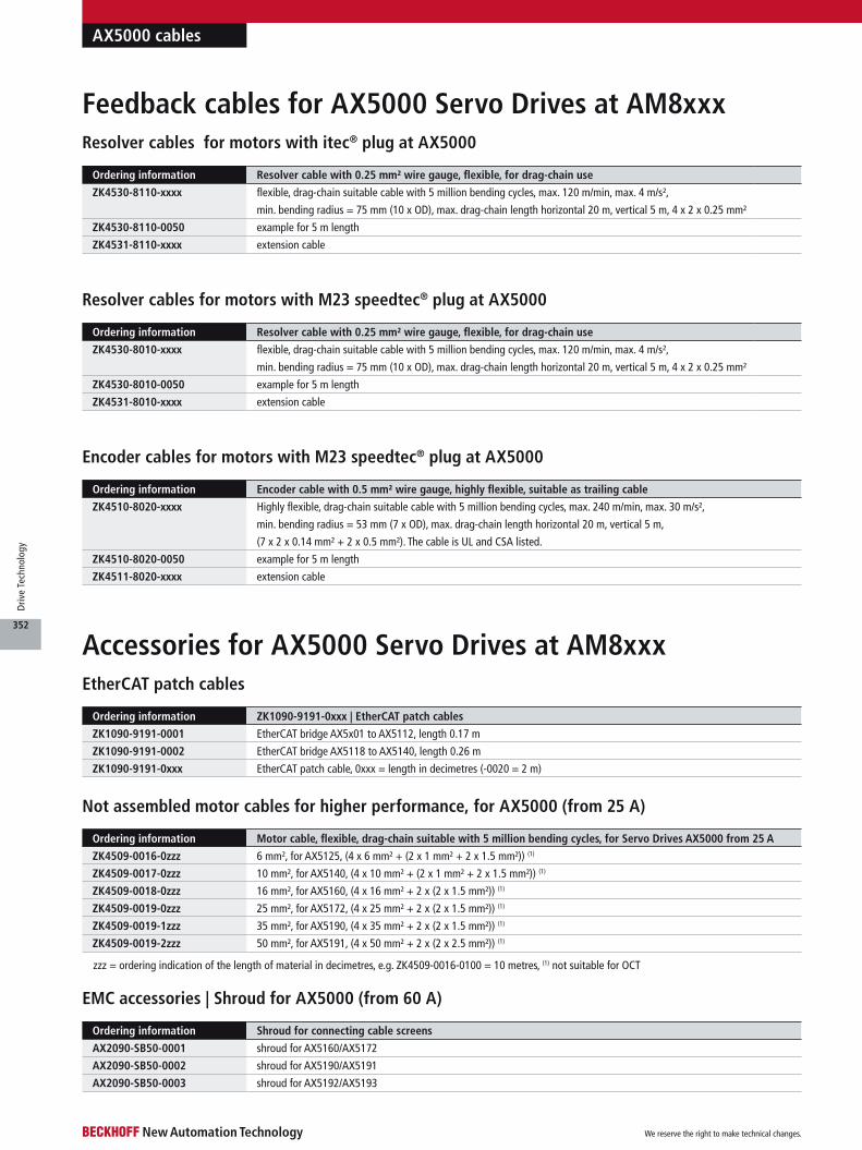
Ordering information Motor cable, flexible, drag-chain suitable with 5 million bending cycles, for Servo Drives AX5000 from 25 A
ZK4509-0016-0zzz 6 mm², for AX5125, (4 x 6 mm² + (2 x 1 mm² + 2 x 1.5 mm²)) (1)
ZK4509-0017-0zzz 10 mm², for AX5140, (4 x 10 mm² + (2 x 1 mm² + 2 x 1.5 mm²)) (1)
ZK4509-0018-0zzz 16 mm², for AX5160, (4 x 16 mm² + 2 x (2 x 1.5 mm²)) (1)
ZK4509-0019-0zzz 25 mm², for AX5172, (4 x 25 mm² + 2 x (2 x 1.5 mm²)) (1)
ZK4509-0019-1zzz 35 mm², for AX5190, (4 x 35 mm² + 2 x (2 x 1.5 mm²)) (1)
ZK4509-0019-2zzz 50 mm², for AX5191, (4 x 50 mm² + 2 x (2 x 2.5 mm²)) (1)
EtherCAT patch cables
Accessories for AX5000 Servo Drives at AM8xxx
Ordering information ZK1090-9191-0xxx | EtherCAT patch cables
ZK1090-9191-0001 EtherCAT bridge AX5x01 to AX5112, length 0.17 m
ZK1090-9191-0002 EtherCAT bridge AX5118 to AX5140, length 0.26 m
ZK1090-9191-0xxx EtherCAT patch cable, 0xxx = length in decimetres (-0020 = 2 m)
Not assembled motor cables for higher performance, for AX5000 (from 25 A)
zzz = ordering indication of the length of material in decimetres, e.g. ZK4509-0016-0100 = 10 metres, (1) not suitable for OCT
Encoder cables for motors with M23 speedtec® plug at AX5000
Ordering information Encoder cable with 0.5 mm² wire gauge, highly flexible, suitable as trailing cable
ZK4510-8020-xxxx Highly flexible, drag-chain suitable cable with 5 million bending cycles, max. 240 m/min, max. 30 m/s²,
min. bending radius = 53 mm (7 x OD), max. drag-chain length horizontal 20 m, vertical 5 m,
(7 x 2 x 0.14 mm² + 2 x 0.5 mm²). The cable is UL and CSA listed.
ZK4510-8020-0050 example for 5 m length
ZK4511-8020-xxxx extension cable
Ordering information Resolver cable with 0.25 mm² wire gauge, flexible, for drag-chain use
ZK4530-8010-xxxx flexible, drag-chain suitable cable with 5 million bending cycles, max. 120 m/min, max. 4 m/s²,
min. bending radius = 75 mm (10 x OD), max. drag-chain length horizontal 20 m, vertical 5 m, 4 x 2 x 0.25 mm²
ZK4530-8010-0050 example for 5 m length
ZK4531-8010-xxxx extension cable
Resolver cables for motors with M23 speedtec® plug at AX5000
Ordering information Resolver cable with 0.25 mm² wire gauge, flexible, for drag-chain use
ZK4530-8110-xxxx flexible, drag-chain suitable cable with 5 million bending cycles, max. 120 m/min, max. 4 m/s²,
min. bending radius = 75 mm (10 x OD), max. drag-chain length horizontal 20 m, vertical 5 m, 4 x 2 x 0.25 mm²
ZK4530-8110-0050 example for 5 m length
ZK4531-8110-xxxx extension cable
Resolver cables for motors with itec® plug at AX5000
Feedback cables for AX5000 Servo Drives at AM8xxx
EMC accessories | Shroud for AX5000 (from 60 A)
Ordering information Shroud for connecting cable screens
AX2090-SB50-0001 shroud for AX5160/AX5172
AX2090-SB50-0002 shroud for AX5190/AX5191
AX2090-SB50-0003 shroud for AX5192/AX5193
AX5000 cables
We reserve the right to make technical changes.
352
Driv
e Te
chno
logy
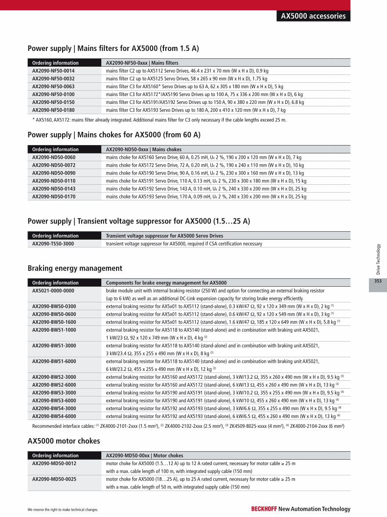
Ordering information Components for brake energy management for AX5000
AX5021-0000-0000 brake module unit with internal braking resistor (250 W) and option for connecting an external braking resistor
(up to 6 kW) as well as an additional DC-Link expansion capacity for storing brake energy efficiently
AX2090-BW50-0300 external braking resistor for AX5x01 to AX5112 (stand-alone), 0.3 kW/47 Ω, 92 x 120 x 349 mm (W x H x D), 2 kg (1)
AX2090-BW50-0600 external braking resistor for AX5x01 to AX5112 (stand-alone), 0.6 kW/47 Ω, 92 x 120 x 549 mm (W x H x D), 3 kg (1)
AX2090-BW50-1600 external braking resistor for AX5x01 to AX5112 (stand-alone), 1.6 kW/47 Ω, 185 x 120 x 649 mm (W x H x D), 5.8 kg (1)
AX2090-BW51-1000 external braking resistor for AX5118 to AX5140 (stand-alone) and in combination with braking unit AX5021,
1 kW/23 Ω, 92 x 120 x 749 mm (W x H x D), 4 kg (2)
AX2090-BW51-3000 external braking resistor for AX5118 to AX5140 (stand-alone) and in combination with braking unit AX5021,
3 kW/23.4 Ω, 355 x 255 x 490 mm (W x H x D), 8 kg (2)
AX2090-BW51-6000 external braking resistor for AX5118 to AX5140 (stand-alone) and in combination with braking unit AX5021,
6 kW/23.2 Ω, 455 x 255 x 490 mm (W x H x D), 12 kg (2)
AX2090-BW52-3000 external braking resistor for AX5160 and AX5172 (stand-alone), 3 kW/13.2 Ω, 355 x 260 x 490 mm (W x H x D), 9.5 kg (3)
AX2090-BW52-6000 external braking resistor for AX5160 and AX5172 (stand-alone), 6 kW/13 Ω, 455 x 260 x 490 mm (W x H x D), 13 kg (3)
AX2090-BW53-3000 external braking resistor for AX5190 and AX5191 (stand-alone), 3 kW/10.2 Ω, 355 x 255 x 490 mm (W x H x D), 9.5 kg (4)
AX2090-BW53-6000 external braking resistor for AX5190 and AX5191 (stand-alone), 6 kW/10 Ω, 455 x 260 x 490 mm (W x H x D), 13 kg (4)
AX2090-BW54-3000 external braking resistor for AX5192 and AX5193 (stand-alone), 3 kW/6.6 Ω, 355 x 255 x 490 mm (W x H x D), 9.5 kg (4)
AX2090-BW54-6000 external braking resistor for AX5192 and AX5193 (stand-alone), 6 kW/6.5 Ω, 455 x 260 x 490 mm (W x H x D), 13 kg (4)
AX5000 accessories
Ordering information AX2090-MD50-00xx | Motor chokes
AX2090-MD50-0012 motor choke for AX5000 (1.5…12 A) up to 12 A rated current, necessary for motor cable ≥ 25 m
with a max. cable length of 100 m, with integrated supply cable (150 mm)
AX2090-MD50-0025 motor choke for AX5000 (18…25 A), up to 25 A rated current, necessary for motor cable ≥ 25 m
with a max. cable length of 50 m, with integrated supply cable (150 mm)
AX5000 motor chokes
Ordering information AX2090-ND50-0xxx | Mains chokes
AX2090-ND50-0060 mains choke for AX5160 Servo Drive, 60 A, 0.25 mH, UK 2 %, 190 x 200 x 120 mm (W x H x D), 7 kg
AX2090-ND50-0072 mains choke for AX5172 Servo Drive, 72 A, 0.20 mH, UK 2 %, 190 x 240 x 110 mm (W x H x D), 10 kg
AX2090-ND50-0090 mains choke for AX5190 Servo Drive, 90 A, 0.16 mH, UK 2 %, 230 x 300 x 160 mm (W x H x D), 13 kg
AX2090-ND50-0110 mains choke for AX5191 Servo Drive, 110 A, 0.13 mH, UK 2 %, 230 x 300 x 180 mm (W x H x D), 15 kg
AX2090-ND50-0143 mains choke for AX5192 Servo Drive, 143 A, 0.10 mH, UK 2 %, 240 x 330 x 200 mm (W x H x D), 25 kg
AX2090-ND50-0170 mains choke for AX5193 Servo Drive, 170 A, 0.09 mH, UK 2 %, 240 x 330 x 200 mm (W x H x D), 25 kg
Ordering information AX2090-NF50-0xxx | Mains filters
AX2090-NF50-0014 mains filter C2 up to AX5112 Servo Drives, 46.4 x 231 x 70 mm (W x H x D), 0.9 kg
AX2090-NF50-0032 mains filter C2 up to AX5125 Servo Drives, 58 x 265 x 90 mm (W x H x D), 1.75 kg
AX2090-NF50-0063 mains filter C3 for AX5160* Servo Drives up to 63 A, 62 x 305 x 180 mm (W x H x D), 5 kg
AX2090-NF50-0100 mains filter C3 for AX5172*/AX5190 Servo Drives up to 100 A, 75 x 336 x 200 mm (W x H x D), 6 kg
AX2090-NF50-0150 mains filter C3 for AX5191/AX5192 Servo Drives up to 150 A, 90 x 380 x 220 mm (W x H x D), 6.8 kg
AX2090-NF50-0180 mains filter C3 for AX5193 Servo Drives up to 180 A, 200 x 410 x 120 mm (W x H x D), 7 kg
Power supply | Mains filters for AX5000 (from 1.5 A)
* AX5160, AX5172: mains filter already integrated. Additional mains filter for C3 only necessary if the cable lengths exceed 25 m.
Power supply | Mains chokes for AX5000 (from 60 A)
Braking energy management
Recommended interface cables: (1) ZK4000-2101-2xxx (1.5 mm²), (2) ZK4000-2102-2xxx (2.5 mm²), (3) ZK4509-8025-xxxx (4 mm²), (4) ZK4000-2104-2xxx (6 mm²)
Ordering information Transient voltage suppressor for AX5000 Servo Drives
AX2090-TS50-3000 transient voltage suppressor for AX5000, required if CSA certification necessary
Power supply | Transient voltage suppressor for AX5000 (1.5…25 A)
We reserve the right to make technical changes.
353
Driv
e Te
chno
logy
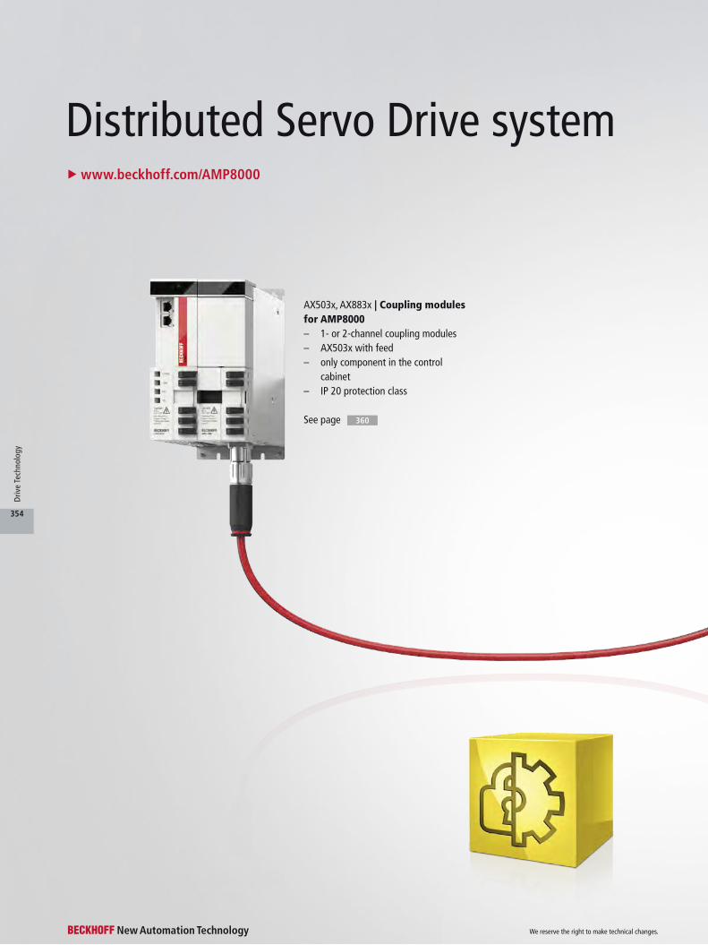
Distributed Servo Drive system
See page 360
u www.beckhoff.com/AMP8000
AX503x, AX883x | Coupling modules for AMP8000– 1- or 2-channel coupling modules– AX503x with feed– only component in the control
cabinet– IP 20 protection class
We reserve the right to make technical changes.
354
Driv
e Te
chno
logy
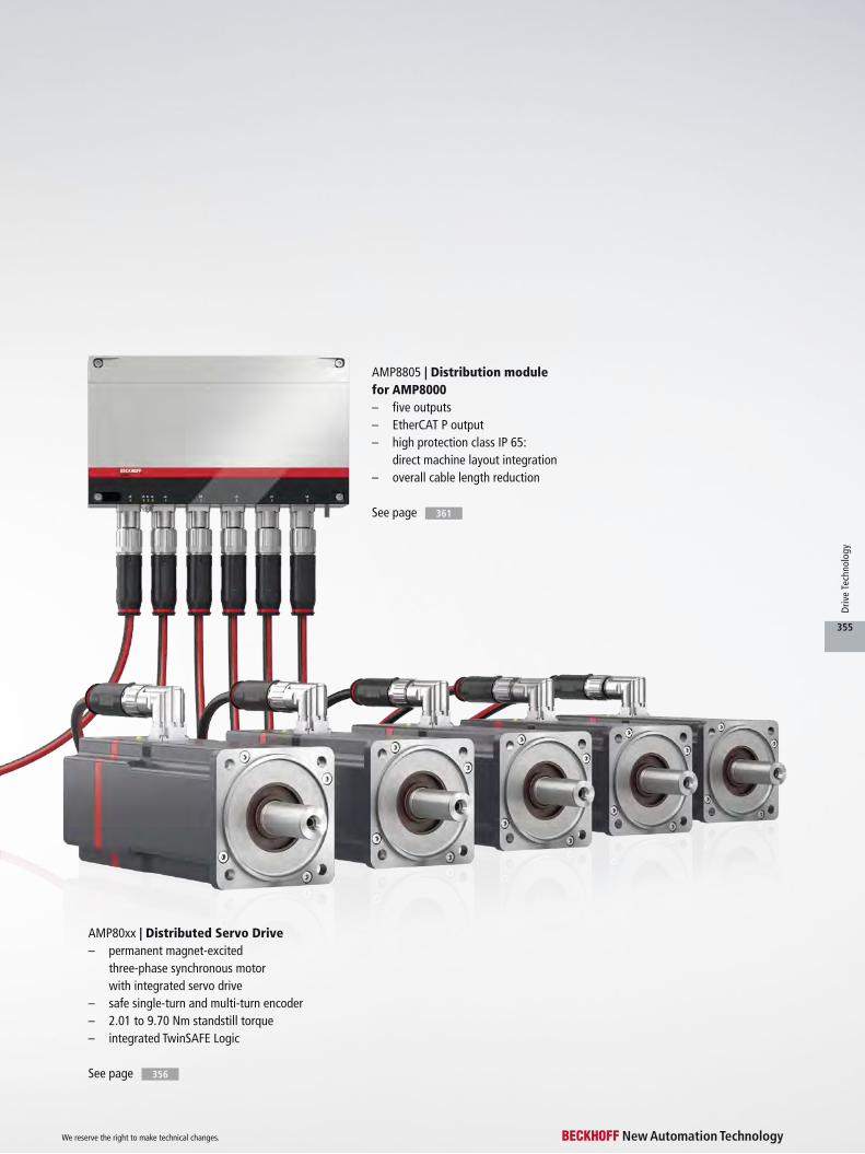
See page 356
See page
AMP8805 | Distribution module for AMP8000– five outputs– EtherCAT P output– high protection class IP 65:
direct machine layout integration– overall cable length reduction
361
AMP80xx | Distributed Servo Drive– permanent magnet-excited
three-phase synchronous motor with integrated servo drive
– safe single-turn and multi-turn encoder– 2.01 to 9.70 Nm standstill torque– integrated TwinSAFE Logic
We reserve the right to make technical changes.
355
Driv
e Te
chno
logy

AMP8000 | Distributed Servo Drive systemu www.beckhoff.com/AMP8000
Safety single-turn and multi-turn encoder
High-efficiency power output stage
Permanent-magnet holding brake with zero backlash
Status LEDs
Rotatable connector
Same attachmentdimensions as thestandard AM8000 and AM8500motor series
Modular design concept for maximum flexibility
High-quality radial bearings– service life: 30,000 hrs– maximum radial and axial load capacity
Powder-coating– scratch-proof– long-lasting
P
We reserve the right to make technical changes.
356
Driv
e Te
chno
logy
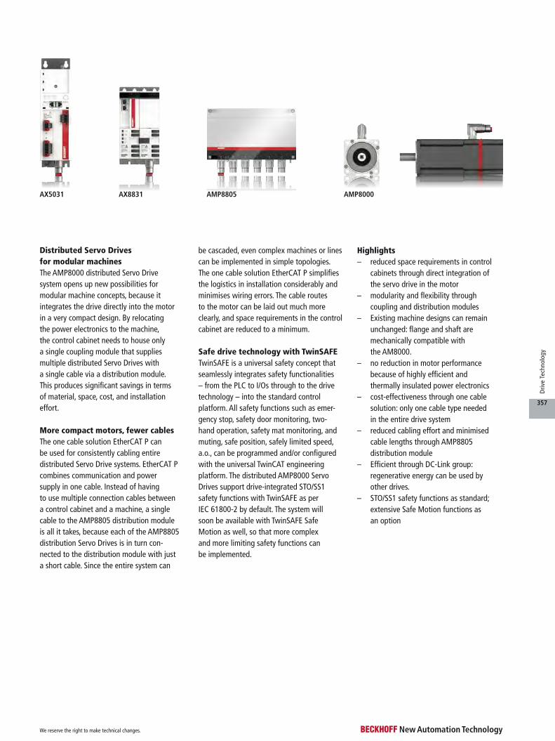
Distributed Servo Drives for modular machinesThe AMP8000 distributed Servo Drive system opens up new possibilities for modular machine concepts, because it integrates the drive directly into the motor in a very compact design. By relocating the power electronics to the machine, the control cabinet needs to house only a single coupling module that supplies multiple distributed Servo Drives with a single cable via a distribution module. This produces significant savings in terms of material, space, cost, and installation effort.
More compact motors, fewer cablesThe one cable solution EtherCAT P can be used for consistently cabling entire distributed Servo Drive systems. EtherCAT P combines communication and power supply in one cable. Instead of having to use multiple connection cables between a control cabinet and a machine, a single cable to the AMP8805 distribution module is all it takes, because each of the AMP8805 distribution Servo Drives is in turn con- nected to the distribution module with just a short cable. Since the entire system can
be cascaded, even complex machines or lines can be implemented in simple topologies. The one cable solution EtherCAT P simplifies the logistics in installation considerably and minimises wiring errors. The cable routes to the motor can be laid out much more clearly, and space requirements in the control cabinet are reduced to a minimum.
Safe drive technology with TwinSAFETwinSAFE is a universal safety concept that seamlessly integrates safety functionalities – from the PLC to I/Os through to the drive technology – into the standard control platform. All safety functions such as emer-gency stop, safety door monitoring, two- hand operation, safety mat monitoring, and muting, safe position, safely limited speed, a.o., can be programmed and/or configured with the universal TwinCAT engineering platform. The distributed AMP8000 Servo Drives support drive-integrated STO/SS1 safety functions with TwinSAFE as per IEC 61800-2 by default. The system will soon be available with TwinSAFE Safe Motion as well, so that more complex and more limiting safety functions can be implemented.
Highlights– reduced space requirements in control
cabinets through direct integration of the servo drive in the motor
– modularity and flexibility through coupling and distribution modules
– Existing machine designs can remain unchanged: flange and shaft are mechanically compatible with the AM8000.
– no reduction in motor performance because of highly efficient and thermally insulated power electronics
– cost-effectiveness through one cable solution: only one cable type needed in the entire drive system
– reduced cabling effort and minimised cable lengths through AMP8805 distribution module
– Efficient through DC-Link group: regenerative energy can be used by other drives.
– STO/SS1 safety functions as standard; extensive Safe Motion functions as an option
AX5031 AX8831 AMP8805 AMP8000
We reserve the right to make technical changes.
357
Driv
e Te
chno
logy

The AMP8000 can be installed in place of a standard AM8000 or AM8500 servomotor. There is no need to modify existing machine design, since only the overall length has been changed, i.e. the other dimensions remain unchanged. Through the use of
the latest output stage tech-nologies, there is minimal derating, i.e. the performance data is almost on a par with the comparable standard motor type.
The AMP8000 is avail-able with flange sizes F4
(2.01…4.80 Nm) and F5 (4.08…9.70 Nm). It can be equipped with either multi- turn or single-turn encoders. TwinSAFE (STO/SS1) is inte- grated as standard; Safe Motion will be available as an option.
AMP80xx | Distributed Servo Drive
AMP8000
Technical data AMP80xx
Motor type permanent magnet-excited three-phase synchronous motor with integrated servo drive
Magnet material neodymium-iron-boron
Insulation class thermal class F (155 °C)
Design form flange-mounted according to IM B5, IM V1, IM V3
Protection class IP 54, IP 65 (shaft seal)
Cooling convection, permissible ambient temperature 40 °C
Coating/surface dark grey powder coating, similar to RAL7016
Temperature sensor integrated in stator winding
Connection method round plug connector, swivelling, angled
Approvals CE, UL in preparation
Feedback system absolute encoder single-turn and multi-turn (OCT)
Options AMP80xx
Feather key groove according to DIN 6885 P1
Holding brake backlash-free permanent magnet single-surface brake, suitable only as holding brake
Shaft seal radial shaft seal made of FPM
Feedback system option safe absolute encoder single- and multi-turn
TwinSAFE
safe drive technology
integrated TwinSAFE Logic, STO, SS1, SS2, SOS, SLS, SDIp, SDIn, SSM, SSR, SMS, SLP,
SCA, SLI, SAR, SMA (in preparation)
We reserve the right to make technical changes.
358
Driv
e Te
chno
logy

Ordering information Motor cable with 2.5 mm² wire gauge, flexible for drag-chain use
ZK7A26-3031-0xxx flexible, drag-chain suitable EtherCAT P cable, mechanical coding 3,
(3 G 2.5 mm² + 2 x 1.5 mm² + (1 x 4 x AWG22)),
ECP B23, plug, straight, female+female, 5+4 pin, EtherCAT-P-coded –
ECP B23, plug, straight, male+male, 5+4 pin, EtherCAT-P-coded,
xxxx = ordering indication of the length of the motor cable in decimetres
You will find the possible ordering options for the distributed Servo Drives listed in this table. Please note: The options cannot be retrofitted. All electrical variables are RMS values.
Ordering options
AMP8000
u www.beckhoff.com/AMP8000
Order reference AMP80uv-wxyz
u flange code F
v motor length
w = 0 smooth shaft
w = 1 shaft with groove and feather key according to DIN 6885
w = 2 smooth shaft with IP 65 sealing ring
w = 3 shaft with IP 65 sealing ring and shaft with groove and feather key
x winding code A…Z
y = 1 safe absolute encoder single-turn, absolute position within one revolution, 24 bit resolution
y = 2 safe absolute encoder multi-turn, absolute position within 4096 revolutions, 24 bit resolution
z = 0 without holding brake
z = 1 with holding brake
Information AMP804x = F4, ECP B23 plug
AMP805x = F5, ECP B23 plug
Data for 560 V DC AMP8041-wDyz AMP8041-wEyz AMP8042-wEyz AMP8043-wEyz
Standstill torque 2.01 Nm 2.01 Nm 3.48 Nm 4.80 Nm
Rated speed 3000 min-1 6000 min-1 2500 min-1 2500 min-1
Rated power 0.61 kW 1.23 kW 0.87 kW 1.18 kW
Standstill current 1.65 A 3.00 A 2.15 A 2.90 A
Connection technology ECP B23 plug
One Cable Technology (OCT) yes
Data for 560 V DC AMP8051-wEyz AMP8051-wGyz AMP8052-wFyz AMP8053-wGyz
Standstill torque 4.08 Nm 4.08 Nm 6.97 Nm 9.70 Nm
Rated speed 2500 min-1 5000 min-1 2000 min-1 2000 min-1
Rated power 1.02 kW 1.02 kW 1.34 kW 1.78 kW
Standstill current 2.70 A 4.75 A 3.30 A 4.70 A
Connection technology ECP B23 plug
One Cable Technology (OCT) yes
Accessories
AMP804x | Flange code F4, motor length 1 – 3
AMP805x | Flange code F5, motor length 1 – 3
For availability status see Beckhoff website at: www.beckhoff.com/AMP8000
We reserve the right to make technical changes.
359
Driv
e Te
chno
logy
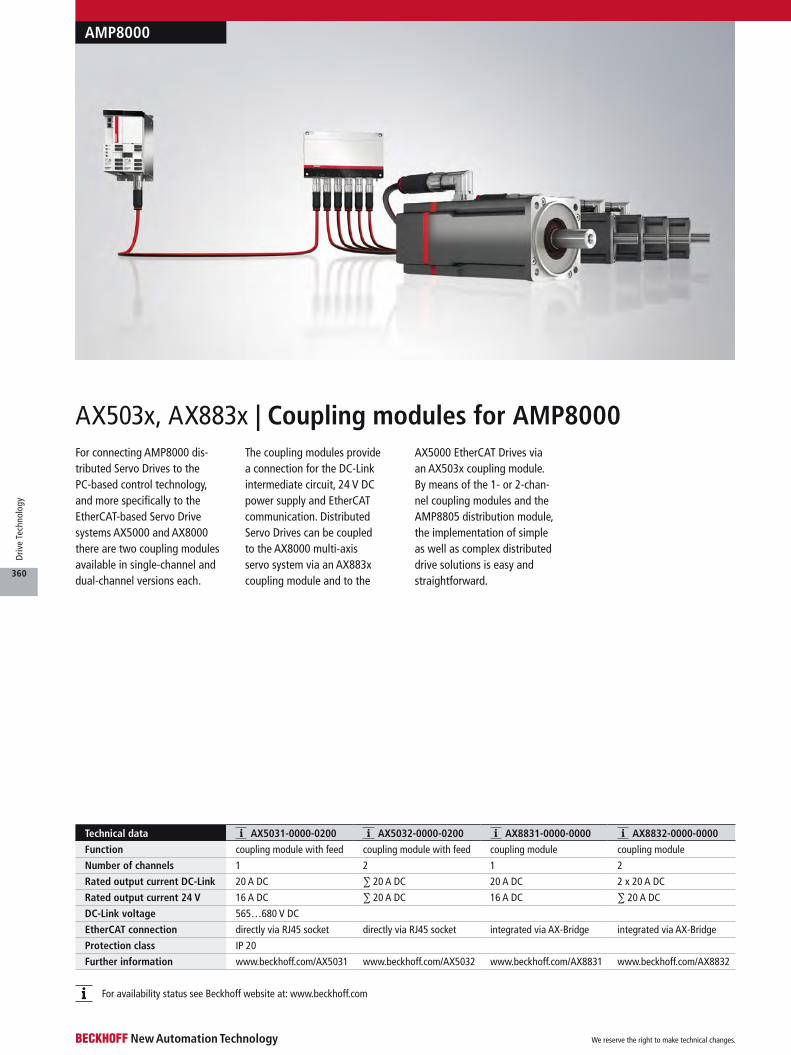
AX503x, AX883x | Coupling modules for AMP8000
Technical data AX5031-0000-0200 AX5032-0000-0200 AX8831-0000-0000 AX8832-0000-0000
Function coupling module with feed coupling module with feed coupling module coupling module
Number of channels 1 2 1 2
Rated output current DC-Link 20 A DC ∑ 20 A DC 20 A DC 2 x 20 A DC
Rated output current 24 V 16 A DC ∑ 20 A DC 16 A DC ∑ 20 A DC
DC-Link voltage 565…680 V DC
EtherCAT connection directly via RJ45 socket directly via RJ45 socket integrated via AX-Bridge integrated via AX-Bridge
Protection class IP 20
Further information www.beckhoff.com/AX5031 www.beckhoff.com/AX5032 www.beckhoff.com/AX8831 www.beckhoff.com/AX8832
AMP8000
For connecting AMP8000 dis-tributed Servo Drives to the PC-based control technology, and more specifically to the EtherCAT-based Servo Drive systems AX5000 and AX8000 there are two coupling modules available in single-channel and dual-channel versions each.
The coupling modules provide a connection for the DC-Link intermediate circuit, 24 V DC power supply and EtherCAT communication. Distributed Servo Drives can be coupled to the AX8000 multi-axis servo system via an AX883x coupling module and to the
AX5000 EtherCAT Drives via an AX503x coupling module. By means of the 1- or 2-chan-nel coupling modules and the AMP8805 distribution module, the implementation of simple as well as complex distributed drive solutions is easy and straightforward.
For availability status see Beckhoff website at: www.beckhoff.com
We reserve the right to make technical changes.
360
Driv
e Te
chno
logy
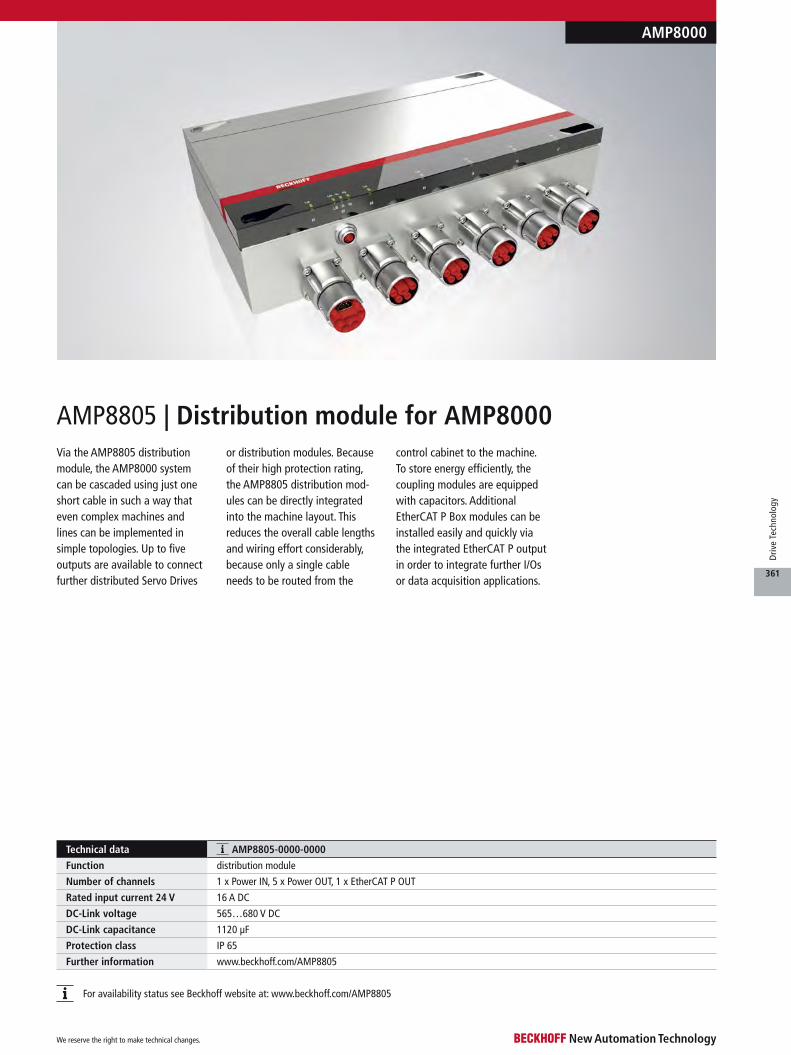
Technical data AMP8805-0000-0000
Function distribution module
Number of channels 1 x Power IN, 5 x Power OUT, 1 x EtherCAT P OUT
Rated input current 24 V 16 A DC
DC-Link voltage 565…680 V DC
DC-Link capacitance 1120 µF
Protection class IP 65
Further information www.beckhoff.com/AMP8805
AMP8805 | Distribution module for AMP8000
AMP8000
Via the AMP8805 distribution module, the AMP8000 system can be cascaded using just one short cable in such a way that even complex machines and lines can be implemented in simple topologies. Up to five outputs are available to connect further distributed Servo Drives
or distribution modules. Because of their high protection rating, the AMP8805 distribution mod-ules can be directly integrated into the machine layout. This reduces the overall cable lengths and wiring effort considerably, because only a single cable needs to be routed from the
control cabinet to the machine. To store energy efficiently, the coupling modules are equipped with capacitors. Additional EtherCAT P Box modules can be installed easily and quickly via the integrated EtherCAT P output in order to integrate further I/Os or data acquisition applications.
For availability status see Beckhoff website at: www.beckhoff.com/AMP8805
We reserve the right to make technical changes.
361
Driv
e Te
chno
logy

Servo and Linear Motors
See page ,364
410compact Drive Technology see page
u www.beckhoff.com/Servomotors
Servomotors– AM8000 for applications with highest demands on dynamics and
performance, One Cable Technology (OCT) for power and feedback– AM8500 with increased internal inertia ratio, One Cable Technology
(OCT) for power and feedbackFor dynamic applications in the lower power range Beckhoff offers the compact Drive Technology series.
Servomotors with forced cooling– higher performance AM8000 and AM8500
motor series due to additional forced cooling– independent 24 V DC fan– standstill torques increased by about 30 %– rated torque at rated speed increased by
up to 150 %
See page 364
We reserve the right to make technical changes.
362
Driv
e Te
chno
logy
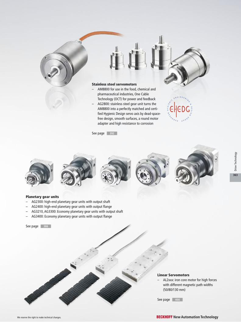
See page 386
See page 392
Stainless steel servomotors– AM8800 for use in the food, chemical and
pharmaceutical industries, One Cable Technology (OCT) for power and feedback
– AG2800: stainless steel gear unit turns the AM8800 into a perfectly matched and certi-fied Hygienic Design servo axis by dead-space- free design, smooth surfaces, a round motor adapter and high resistance to corrosion
See page 400
Linear Servomotors– AL2xxx: iron core motor for high forces
with different magnetic path widths (50/80/130 mm)
Planetary gear units– AG2300: high-end planetary gear units with output shaft– AG2400: high-end planetary gear units with output flange– AG3210, AG3300: Economy planetary gear units with output shaft– AG3400: Economy planetary gear units with output flange
We reserve the right to make technical changes.
363
Driv
e Te
chno
logy
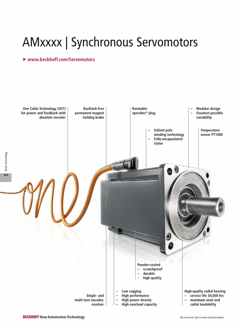
AMxxxx | Synchronous Servomotors
Single- and multi-turn encoder,
resolver
– Modular design– Greatest possible variability
High-quality radial bearing– service life 30,000 hrs– maximum axial and
radial loadability
Powder-coated– scratchproof– durable– high quality
– Low cogging– High performance– High power density– High overload capacity
– Salient-pole winding technology– Fully-encapsulated
stator
Temperature sensor PT1000
Rotatable speedtec® plug
One Cable Technology (OCT) for power and feedback with
absolute encoder
Backlash-free permanent magnet
holding brake
u www.beckhoff.com/Servomotors
We reserve the right to make technical changes.
364
Driv
e Te
chno
logy
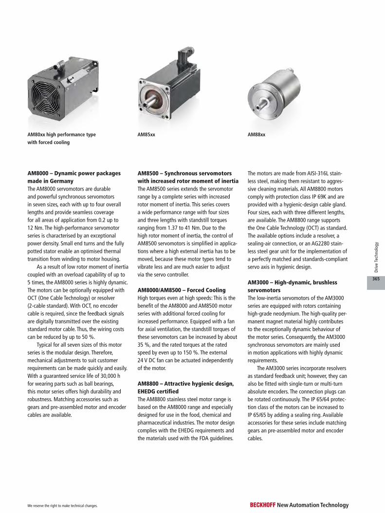
AM88xxAM80xx high performance type
with forced cooling
AM85xx
AM8000 – Dynamic power packages made in GermanyThe AM8000 servomotors are durable and powerful synchronous servomotors in seven sizes, each with up to four overall lengths and provide seamless coverage for all areas of application from 0.2 up to 12 Nm. The high-performance servomotor series is characterised by an exceptional power density. Small end turns and the fully potted stator enable an optimised thermal transition from winding to motor housing.
As a result of low rotor moment of inertia coupled with an overload capability of up to 5 times, the AM8000 series is highly dynamic. The motors can be optionally equipped with OCT (One Cable Technology) or resolver (2-cable standard). With OCT, no encoder cable is required, since the feedback signals are digitally transmitted over the existing standard motor cable. Thus, the wiring costs can be reduced by up to 50 %.
Typical for all seven sizes of this motor series is the modular design. Therefore, mechanical adjustments to suit customer requirements can be made quickly and easily. With a guaranteed service life of 30,000 h for wearing parts such as ball bearings, this motor series offers high durability and robustness. Matching accessories such as gears and pre-assembled motor and encoder cables are available.
AM8500 – Synchronous servomotors with increased rotor moment of inertiaThe AM8500 series extends the servomotor range by a complete series with increased rotor moment of inertia. This series covers a wide performance range with four sizes and three lengths with standstill torques ranging from 1.37 to 41 Nm. Due to the high rotor moment of inertia, the control of AM8500 servomotors is simplified in applica-tions where a high external inertia has to be moved, because these motor types tend to vibrate less and are much easier to adjust via the servo controller.
AM8000/AM8500 – Forced CoolingHigh torques even at high speeds: This is the benefit of the AM8000 and AM8500 motor series with additional forced cooling for increased performance. Equipped with a fan for axial ventilation, the standstill torques of these servomotors can be increased by about 35 %, and the rated torques at the rated speed by even up to 150 %. The external 24 V DC fan can be actuated independently of the motor.
AM8800 – Attractive hygienic design, EHEDG certifiedThe AM8800 stainless steel motor range is based on the AM8000 range and especially designed for use in the food, chemical and pharmaceutical industries. The motor design complies with the EHEDG requirements and the materials used with the FDA guidelines.
The motors are made from AISI-316L stain-less steel, making them resistant to aggres-sive cleaning materials. All AM8800 motors comply with protection class IP 69K and are provided with a hygienic-design cable gland. Four sizes, each with three different lengths, are available. The AM8800 range supports the One Cable Technology (OCT) as standard. The available options include a resolver, a sealing-air connection, or an AG2280 stain-less steel gear unit for the implementation of a perfectly matched and standards-compliant servo axis in hygienic design.
AM3000 – High-dynamic, brushless servomotorsThe low-inertia servomotors of the AM3000 series are equipped with rotors containing high-grade neodymium. The high-quality per-manent magnet material highly contributes to the exceptionally dynamic behaviour of the motor series. Consequently, the AM3000 synchronous servomotors are mainly used in motion applications with highly dynamic requirements.
The AM3000 series incorporate resolvers as standard feedback unit; however, they can also be fitted with single-turn or multi-turn absolute encoders. The connection plugs can be rotated continuously. The IP 65/64 protec-tion class of the motors can be increased to IP 65/65 by adding a sealing ring. Available accessories for these series include matching gears an pre-assembled motor and encoder cables.
We reserve the right to make technical changes.
365
Driv
e Te
chno
logy

AM8000 | Synchronous ServomotorsThe AM8000 series represents robust, durable and high-per-formance synchronous servo-motors “Made in Germany”. The seven flange codes, with up to four overall lengths, cover a wide torque range from 0.2 up to 129 Nm.
The AM8000 motors feature a low rotor moment of inertia and a very high overload capac-ity. Based on these technical characteristics, the most highly dynamic applications can be realised.
The windings of the AM8000 motors are implemented using salient pole-wound technology, resulting in a high copper space
factor. Due to the high slot space factor, high continuous torques can be achieved. The fully pot-ted stator provides for an ideal thermal transition from winding to housing. Another advantage is mechanical protection of the winding wires against vibrations.
Amply sized, sealed grooved ball bearings in conjunction with a sophisticated mechanical design ensure a bearing service life of 30,000 hours. All motors feature an integrated PT1000 temperature sensor for exact temperature evaluation.
In the forced-cooling ver-sion, the power density of the AM8000 motor series can be
further increased by means of external axial ventilation. This option is available for the AM806x to AM807x sizes.
The modular design of the AM8000 motors enables rapid implementation of mechanical adjustments. Customer-specific variants are available. The motors offer an electronic identification plate for simple commissioning.
The housing is fully powder-coated so that cutting edges are covered. The acrylic powder coat-ing also offers high resistance against scratching and corrosion. In the basic version, AM8000 motors feature IP 54 protected
housings. For harsh environ-mental conditions, the shaft feedthrough can optionally be equipped with an FPM sealing ring (fluoropolymer rubber), so that the whole motor is IP 65 protected.
Planetary gear units see page
Pre-assembled cables see page 350
386
Technical data AM80xx
Motor type permanent magnet-excited three-phase synchronous motor
Magnet material neodymium-iron-boron
Insulation class thermal class F (155 °C)
Design form flange-mounted according to IM B5, IM V1, IM V3
Protection class IP 54, IP 65 (shaft seal)
Cooling convection, permissible ambient temperature 40 °C, optionally: external axial ventilation
Coating/surface dark grey powder coating, similar to RAL7016
Temperature sensor integrated in stator winding
Connection method round plug connector, swivelling, angled; terminal box according to winding type
Life span L10h = 30,000 hrs for ball bearings
Approvals CE, UL
Feedback system absolute encoder single-turn and multi-turn, OCT, resolver, multi-turn 2-cable standard
AM8000
We reserve the right to make technical changes.
366
Driv
e Te
chno
logy
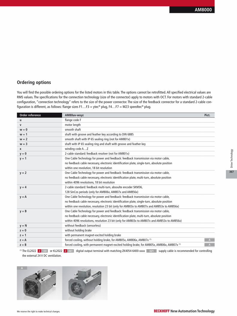
You will find the possible ordering options for the listed motors in this table. The options cannot be retrofitted. All specified electrical values are RMS values. The specifications for the connection technology (size of the connector) apply to motors with OCT. For motors with standard 2-cable configuration, “connection technology” refers to the size of the power connector. The size of the feedback connector for a standard 2-cable con-figuration is different, as follows: flange sizes F1…F3 = ytec® plug, F4…F7 = M23 speedtec® plug.
Order reference AM80uv-wxyz Pict.
u flange code F
v motor length
w = 0 smooth shaft
w = 1 shaft with groove and feather key according to DIN 6885
w = 2 smooth shaft with IP 65 sealing ring (not for AM801x)
w = 3 shaft with IP 65 sealing ring and shaft with groove and feather key
x winding code A…Z
y = 0 2-cable standard: feedback resolver (not for AM801x)
y = 1 One Cable Technology for power and feedback: feedback transmission via motor cable,
no feedback cable necessary, electronic identification plate, single-turn, absolute position
within one revolution, 18 bit resolution
y = 2 One Cable Technology for power and feedback: feedback transmission via motor cable,
no feedback cable necessary, electronic identification plate, multi-turn, absolute position
within 4096 revolutions, 18 bit resolution
y = 4 2-cable standard: feedback multi-turn, absoulte encoder SKM36,
128 SinCos periods (only for AM806x, AM807x and AM856x)
y = A One Cable Technology for power and feedback: feedback transmission via motor cable,
no feedback cable necessary, electronic identification plate, single-turn, absolute position
within one revolution, resolution 23 bit (only for AM803x to AM807x and AM853x to AM856x)
y = B One Cable Technology for power and feedback: feedback transmission via motor cable,
no feedback cable necessary, electronic identification plate, multi-turn, absolute position
within 4096 revolutions, resolution 23 bit (only for AM803x to AM807x and AM853x to AM856x)
y = N without feedback (sensorless)
z = 0 without holding brake
z = 1 with permanent magnet-excited holding brake
z = A forced cooling, without holding brake, for AM805x, AM806x, AM807x (1)
z = B forced cooling, with permanent magnet-excited holding brake, for AM805x, AM806x, AM807x (1)
AM8000
Ordering options
(1) The EL2022 or KL2022 digital output terminal with matching ZK4054-6400-xxxx supply cable is recommended for controlling
the external 24 V DC ventilation.
461
A
A
A
2 2 321130
We reserve the right to make technical changes.
367
Driv
e Te
chno
logy
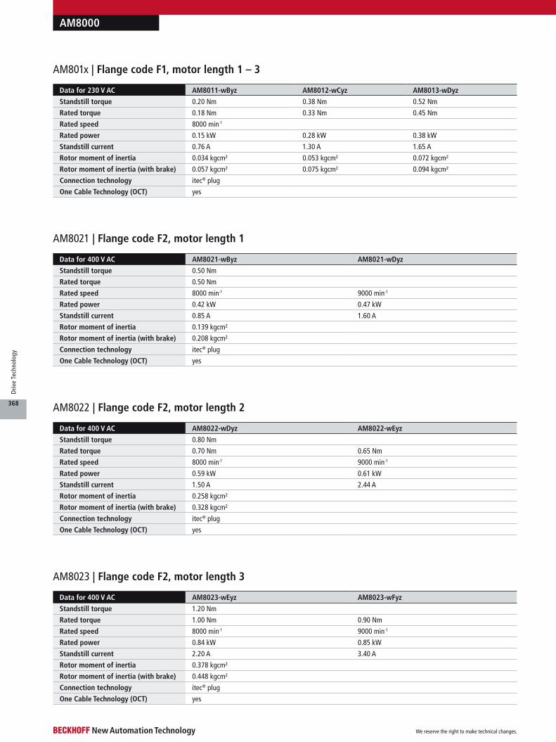
AM8000
Data for 400 V AC AM8021-wByz AM8021-wDyz
Standstill torque 0.50 Nm
Rated torque 0.50 Nm
Rated speed 8000 min-1 9000 min-1
Rated power 0.42 kW 0.47 kW
Standstill current 0.85 A 1.60 A
Rotor moment of inertia 0.139 kgcm²
Rotor moment of inertia (with brake) 0.208 kgcm²
Connection technology itec® plug
One Cable Technology (OCT) yes
AM8021 | Flange code F2, motor length 1
Data for 400 V AC AM8022-wDyz AM8022-wEyz
Standstill torque 0.80 Nm
Rated torque 0.70 Nm 0.65 Nm
Rated speed 8000 min-1 9000 min-1
Rated power 0.59 kW 0.61 kW
Standstill current 1.50 A 2.44 A
Rotor moment of inertia 0.258 kgcm²
Rotor moment of inertia (with brake) 0.328 kgcm²
Connection technology itec® plug
One Cable Technology (OCT) yes
AM8022 | Flange code F2, motor length 2
Data for 400 V AC AM8023-wEyz AM8023-wFyz
Standstill torque 1.20 Nm
Rated torque 1.00 Nm 0.90 Nm
Rated speed 8000 min-1 9000 min-1
Rated power 0.84 kW 0.85 kW
Standstill current 2.20 A 3.40 A
Rotor moment of inertia 0.378 kgcm²
Rotor moment of inertia (with brake) 0.448 kgcm²
Connection technology itec® plug
One Cable Technology (OCT) yes
AM8023 | Flange code F2, motor length 3
Data for 230 V AC AM8011-wByz AM8012-wCyz AM8013-wDyz
Standstill torque 0.20 Nm 0.38 Nm 0.52 Nm
Rated torque 0.18 Nm 0.33 Nm 0.45 Nm
Rated speed 8000 min-1
Rated power 0.15 kW 0.28 kW 0.38 kW
Standstill current 0.76 A 1.30 A 1.65 A
Rotor moment of inertia 0.034 kgcm² 0.053 kgcm² 0.072 kgcm²
Rotor moment of inertia (with brake) 0.057 kgcm² 0.075 kgcm² 0.094 kgcm²
Connection technology itec® plug
One Cable Technology (OCT) yes
AM801x | Flange code F1, motor length 1 – 3
We reserve the right to make technical changes.
368
Driv
e Te
chno
logy

AM8000
Data for 400 V AC AM8031-wCyz AM8031-wDyz AM8031-wFyz
Standstill torque 1.37 Nm 1.38 Nm 1.40 Nm
Rated torque 1.34 Nm 1.33 Nm 1.30 Nm
Rated speed 3000 min-1 6000 min-1 9000 min-1
Rated power 0.42 kW 0.84 kW 1.23 kW
Standstill current 1.00 A 1.95 A 3.20 A
Rotor moment of inertia 0.467 kgcm²
Rotor moment of inertia (with brake) 0.546 kgcm²
Connection technology itec® plug
One Cable Technology (OCT) yes
AM8031 | Flange code F3, motor length 1
Data for 400 V AC AM8032-wDyz AM8032-wEyz AM8032-wHyz
Standstill torque 2.38 Nm 2.37 Nm 2.37 Nm
Rated torque 2.30 Nm 2.20 Nm 1.85 Nm
Rated speed 3000 min-1 6000 min-1 9000 min-1
Rated power 0.72 kW 1.38 kW 1.74 kW
Standstill current 1.70 A 2.95 A 5.10 A
Rotor moment of inertia 0.847 kgcm²
Rotor moment of inertia (with brake) 0.926 kgcm²
Connection technology itec® plug
One Cable Technology (OCT) yes
AM8032 | Flange code F3, motor length 2
Data for 400 V AC AM8033-wEyz AM8033-wFyz AM8033-wJyz
Standstill torque 3.20 Nm 3.22 Nm 3.22 Nm
Rated torque 2.98 Nm 2.70 Nm 2.30 Nm
Rated speed 3000 min-1 6000 min-1 9000 min-1
Rated power 0.94 kW 1.70 kW 2.17 kW
Standstill current 2.10 A 4.10 A 6.80 A
Rotor moment of inertia 1.23 kgcm²
Rotor moment of inertia (with brake) 1.46 kgcm²
Connection technology itec® plug
One Cable Technology (OCT) yes
AM8033 | Flange code F3, motor length 3
Data for 400 V AC AM8041-wDyz AM8041-wEyz AM8041-wHyz
Standstill torque 2.37 Nm 2.45 Nm 2.40 Nm
Rated torque 2.30 Nm 2.31 Nm 2.10 Nm
Rated speed 3000 min-1 6000 min-1 8000 min-1
Rated power 0.72 kW 1.45 kW 1.76 kW
Standstill current 1.65 A 3.00 A 5.25 A
Rotor moment of inertia 1.09 kgcm²
Rotor moment of inertia (with brake) 1.73 kgcm²
Connection technology M23 speedtec® plug
One Cable Technology (OCT) yes
AM8041 | Flange code F4, motor length 1
We reserve the right to make technical changes.
369
Driv
e Te
chno
logy

AM8000
Data for 400 V AC AM8042-wEyz AM8042-wFyz AM8042-wJyz
Standstill torque 4.10 Nm
Rated torque 3.90 Nm 3.70 Nm 3.10 Nm
Rated speed 2500 min-1 5000 min-1 8000 min-1
Rated power 1.02 kW 1.94 kW 2.60 kW
Standstill current 2.15 A 4.10 A 6.90 A
Rotor moment of inertia 1.98 kgcm²
Rotor moment of inertia (with brake) 2.63 kgcm²
Connection technology M23 speedtec® plug
One Cable Technology (OCT) yes
AM8042 | Flange code F4, motor length 2
Data for 400 V AC AM8043-wEyz AM8043-wHyz AM8043-wKyz
Standstill torque 5.65 Nm 5.65 Nm 5.60 Nm
Rated torque 5.30 Nm 4.90 Nm 4.10 Nm
Rated speed 2500 min-1 5000 min-1 8000 min-1
Rated power 1.39 kW 2.57 kW 3.43 kW
Standstill current 2.90 A 5.40 A 9.30 A
Rotor moment of inertia 2.87 kgcm²
Rotor moment of inertia (with brake) 3.52 kgcm²
Connection technology M23 speedtec® plug
One Cable Technology (OCT) yes
AM8043 | Flange code F4, motor length 3
Data for 400 V AC AM8051-wEyz AM8051-wGyz AM8051-wKyz
Standstill torque 4.80 Nm 4.90 Nm 4.90 Nm
Rated torque 4.60 Nm 4.40 Nm 3.90 Nm
Rated speed 2500 min-1 5000 min-1 8000 min-1
Rated power 1.20 kW 2.30 kW 3.27 kW
Standstill current 2.70 A 4.75 A 8.50 A
Rotor moment of inertia 2.25 kgcm²
Rotor moment of inertia (with brake) 2.91 kgcm²
Connection technology M23 speedtec® plug
One Cable Technology (OCT) yes
AM8051 | Flange code F5, motor length 1
AM8051 | Flange code F5, motor length 1, high-performance type with forced cooling
Data for 400 V AC AM8051-wFyz AM8051-wJyz AM8051-wLyz
Standstill torque 6.20 Nm 6.30 Nm 6.30 Nm
Rated torque 5.8 Nm 5.5 Nm 3.6 Nm
Rated speed 2500 min-1 4750 min-1 8000 min-1
Rated power 1.52 kW 2.74 kW 3.02 kW
Standstill current 3.50 A 5.80 A 11.1 A
Rotor moment of inertia 2.24 kgcm²
Rotor moment of inertia (with brake) 2.90 kgcm²
Connection technology M23 speedtec® plug
One Cable Technology (OCT) yes
We reserve the right to make technical changes.
370
Driv
e Te
chno
logy

AM8000
Data for 400 V AC AM8052-wFyz AM8052-wJyz AM8052-wLyz
Standstill torque 8.20 Nm
Rated torque 7.50 Nm 6.90 Nm 5.40 Nm
Rated speed 2000 min-1 4000 min-1 7300 min-1
Rated power 1.57 kW 2.89 kW 4.13 kW
Standstill current 3.30 A 6.30 A 11.3 A
Rotor moment of inertia 4.09 kgcm²
Rotor moment of inertia (with brake) 4.75 kgcm²
Connection technology M23 speedtec® plug
One Cable Technology (OCT) yes
AM8052 | Flange code F5, motor length 2
AM8052 | Flange code F5, motor length 2, high-performance type with forced cooling
Data for 400 V AC AM8053-wGyz AM8053-wKyz AM8053-wNyz
Standstill torque 11.4 Nm
Rated torque 10.0 Nm 8.35 Nm 4.50 Nm
Rated speed 2000 min-1 4000 min-1 7000 min-1
Rated power 2.09 kW 3.50 kW 3.30 kW
Standstill current 4.70 A 8.80 A 15.6 A
Rotor moment of inertia 5.93 kgcm²
Rotor moment of inertia (with brake) 7.04 kgcm²
Connection technology M23 speedtec® plug
One Cable Technology (OCT) yes
AM8053 | Flange code F5, motor length 3
AM8053 | Flange code F5, motor length 3, high-performance type with forced cooling
Data for 400 V AC AM8052-wGyz AM8052-wKyz AM8052-wNyz
Standstill torque 10.7 Nm 10.7 Nm 9.6 Nm
Rated torque 9.7 Nm 9.1 Nm 5.4 Nm
Rated speed 2000 min-1 4000 min-1 6000 min-1
Rated power 2.03 kW 3.77 kW 4.08 kW
Standstill current 4.30 A 8.50 A 13.6 A
Rotor moment of inertia 4.08 kgcm²
Rotor moment of inertia (with brake) 4.74 kgcm²
Connection technology M23 speedtec® plug
One Cable Technology (OCT) yes
Data for 400 V AC AM8053-wJyz AM8053-wLyz AM8053-wPyz
Standstill torque 15.4 Nm 15.4 Nm 13.3 Nm
Rated torque 14.9 Nm 12.9 Nm 7.1 Nm
Rated speed 2000 min-1 4000 min-1 5000 min-1
Rated power 3.12 kW 5.41 kW 3.72 kW
Standstill current 6.40 A 11.9 A 18.6 A
Rotor moment of inertia 5.92 kgcm²
Rotor moment of inertia (with brake) 7.04 kgcm²
Connection technology M23 speedtec® plug
One Cable Technology (OCT) yes
We reserve the right to make technical changes.
371
Driv
e Te
chno
logy
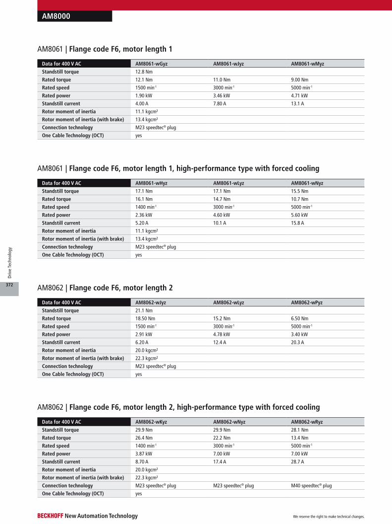
AM8000
Data for 400 V AC AM8061-wGyz AM8061-wJyz AM8061-wMyz
Standstill torque 12.8 Nm
Rated torque 12.1 Nm 11.0 Nm 9.00 Nm
Rated speed 1500 min-1 3000 min-1 5000 min-1
Rated power 1.90 kW 3.46 kW 4.71 kW
Standstill current 4.00 A 7.80 A 13.1 A
Rotor moment of inertia 11.1 kgcm²
Rotor moment of inertia (with brake) 13.4 kgcm²
Connection technology M23 speedtec® plug
One Cable Technology (OCT) yes
AM8061 | Flange code F6, motor length 1
AM8061 | Flange code F6, motor length 1, high-performance type with forced cooling
Data for 400 V AC AM8062-wJyz AM8062-wLyz AM8062-wPyz
Standstill torque 21.1 Nm
Rated torque 18.50 Nm 15.2 Nm 6.50 Nm
Rated speed 1500 min-1 3000 min-1 5000 min-1
Rated power 2.91 kW 4.78 kW 3.40 kW
Standstill current 6.20 A 12.4 A 20.3 A
Rotor moment of inertia 20.0 kgcm²
Rotor moment of inertia (with brake) 22.3 kgcm²
Connection technology M23 speedtec® plug
One Cable Technology (OCT) yes
AM8062 | Flange code F6, motor length 2
AM8062 | Flange code F6, motor length 2, high-performance type with forced cooling
Data for 400 V AC AM8062-wKyz AM8062-wNyz AM8062-wRyz
Standstill torque 29.9 Nm 29.9 Nm 28.1 Nm
Rated torque 26.4 Nm 22.2 Nm 13.4 Nm
Rated speed 1400 min-1 3000 min-1 5000 min-1
Rated power 3.87 kW 7.00 kW 7.00 kW
Standstill current 8.70 A 17.4 A 28.7 A
Rotor moment of inertia 20.0 kgcm²
Rotor moment of inertia (with brake) 22.3 kgcm²
Connection technology M23 speedtec® plug M23 speedtec® plug M40 speedtec® plug
One Cable Technology (OCT) yes
Data for 400 V AC AM8061-wHyz AM8061-wLyz AM8061-wNyz
Standstill torque 17.1 Nm 17.1 Nm 15.5 Nm
Rated torque 16.1 Nm 14.7 Nm 10.7 Nm
Rated speed 1400 min-1 3000 min-1 5000 min-1
Rated power 2.36 kW 4.60 kW 5.60 kW
Standstill current 5.20 A 10.1 A 15.8 A
Rotor moment of inertia 11.1 kgcm²
Rotor moment of inertia (with brake) 13.4 kgcm²
Connection technology M23 speedtec® plug
One Cable Technology (OCT) yes
We reserve the right to make technical changes.
372
Driv
e Te
chno
logy

AM8000
Data for 400 V AC AM8063-wKyz AM8063-wNyz AM8063-wRyz
Standstill torque 29.0 Nm
Rated torque 22.3 Nm 13.2 Nm 6.10 Nm
Rated speed 1500 min-1 3000 min-1 4000 min-1
Rated power 3.50 kW 4.15 kW 2.56 kW
Standstill current 8.70 A 17.2 A 29.5 A
Rotor moment of inertia 29.0 kgcm²
Rotor moment of inertia (with brake) 34.9 kgcm²
Connection technology M23 speedtec® plug M23 speedtec® plug M40 speedtec® plug
One Cable Technology (OCT) yes
AM8063 | Flange code F6, motor length 3
AM8063 | Flange code F6, motor length 3, high-performance type with forced cooling
Data for 400 V AC AM8063-wLyz AM8063-wQyz AM8063-wTyz
Standstill torque 41.4 Nm 41.4 Nm 40.1 Nm
Rated torque 33.9 Nm 25.5 Nm 15.1 Nm
Rated speed 1400 min-1 3000 min-1 4000 min-1
Rated power 4.97 kW 8.00 kW 6.30 kW
Standstill current 11.6 A 24.0 A 39.8 A
Rotor moment of inertia 29.0 kgcm²
Rotor moment of inertia (with brake) 34.9 kgcm²
Connection technology M23 speedtec® plug M40 speedtec® plug M40 speedtec® plug
One Cable Technology (OCT) yes
Data for 400 V AC AM8064-wNyA AM8064-wRyA AM8064-wTyA
Standstill torque 49.0 Nm
Rated torque 33.0 Nm 26.0 Nm 10.0 Nm
Rated speed 1000 min-1 2000 min-1 3000 min-1
Rated power 3.45 kW 5.44 kW 3.10 kW
Standstill current 14.6 A 29.4 A 49.0 A
Rotor moment of inertia 38.6 kgcm²
Connection technology M23 speedtec® plug M40 speedtec® plug terminal box
One Cable Technology (OCT) yes yes –
Data for 400 V AC AM8064-wLy0 AM8064-wQy0 AM8064-wTy0
Standstill torque 35.0 Nm
Rated torque 24.0 Nm 19.0 Nm 6.50 Nm
Rated speed 1500 min-1 2000 min-1 3000 min-1
Rated power 2.51 kW 3.98 kW 2.00 kW
Standstill current 10.4 A 21.0 A 35.0 A
Rotor moment of inertia 38.6 kgcm²
Connection technology M23 speedtec® plug M23 speedtec® plug M40 speedtec® plug
One Cable Technology (OCT) yes
AM8064 | Flange code F6, motor length 4
AM8064 | Flange code F6, motor length 4, high-performance type with forced cooling
We reserve the right to make technical changes.
373
Driv
e Te
chno
logy
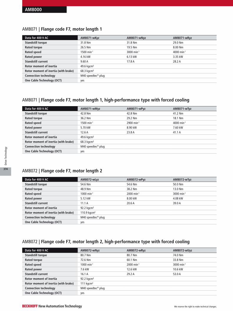
AM8000
Data for 400 V AC AM8072-wLyz AM8072-wPyz AM8072-wTyz
Standstill torque 54.6 Nm 54.6 Nm 50.0 Nm
Rated torque 48.9 Nm 38.2 Nm 13.0 Nm
Rated speed 1000 min-1 2000 min-1 3000 min-1
Rated power 5.12 kW 8.00 kW 4.08 kW
Standstill current 11.1 A 20.6 A 39.0 A
Rotor moment of inertia 92.2 kgcm²
Rotor moment of inertia (with brake) 110.9 kgcm²
Connection technology M40 speedtec® plug
One Cable Technology (OCT) yes
AM8072 | Flange code F7, motor length 2
AM8072 | Flange code F7, motor length 2, high-performance type with forced cooling
Data for 400 V AC AM8072-wNyz AM8072-wRyz AM8072-wUyz
Standstill torque 80.7 Nm 80.7 Nm 74.0 Nm
Rated torque 72.6 Nm 60.1 Nm 33.8 Nm
Rated speed 1000 min-1 2000 min-1 3000 min-1
Rated power 7.6 kW 12.6 kW 10.6 kW
Standstill current 16.1 A 29.2 A 53.0 A
Rotor moment of inertia 92.2 kgcm²
Rotor moment of inertia (with brake) 111 kgcm²
Connection technology M40 speedtec® plug
One Cable Technology (OCT) yes
Data for 400 V AC AM8071-wKyz AM8071-wNyz AM8071-wRyz
Standstill torque 31.8 Nm 31.8 Nm 29.0 Nm
Rated torque 26.5 Nm 19.5 Nm 8.00 Nm
Rated speed 1500 min-1 3000 min-1 4000 min-1
Rated power 4.16 kW 6.13 kW 3.35 kW
Standstill current 9.60 A 17.8 A 28.2 A
Rotor moment of inertia 49.6 kgcm²
Rotor moment of inertia (with brake) 68.3 kgcm²
Connection technology M40 speedtec® plug
One Cable Technology (OCT) yes
AM8071 | Flange code F7, motor length 1
AM8071 | Flange code F7, motor length 1, high-performance type with forced cooling
Data for 400 V AC AM8071-wMyz AM8071-wPyz AM8071-wTyz
Standstill torque 42.8 Nm 42.8 Nm 41.2 Nm
Rated torque 36.2 Nm 29.2 Nm 18.1 Nm
Rated speed 1500 min-1 2900 min-1 4000 min-1
Rated power 5.70 kW 8.90 kW 7.60 kW
Standstill current 12.6 A 23.8 A 41.1 A
Rotor moment of inertia 49.6 kgcm²
Rotor moment of inertia (with brake) 68.3 kgcm²
Connection technology M40 speedtec® plug
One Cable Technology (OCT) yes
We reserve the right to make technical changes.
374
Driv
e Te
chno
logy

AM8000
AM8073 | Flange code F7, motor length 3
AM8073 | Flange code F7, motor length 3, high-performance type with forced cooling
Data for 400 V AC AM8074-wNy0 AM8074-wRy0 AM8074-wTy0
Standstill torque 92 Nm
Rated torque 67 Nm 34 Nm 19.1 Nm
Rated speed 1000 min-1 2000 min-1 2500 min-1
Rated power 7.02 kW 7.12 kW 5.0 kW
Standstill current 17.4 A 34.9 A 49.8 A
Rotor moment of inertia 180 kgcm²
Connection technology M40 speedtec® plug M40 speedtec® plug terminal box
One Cable Technology (OCT) yes yes –
AM8074 | Flange code F7, motor length 4
Data for 400 V AC AM8074-wRyA AM8074-wTyA AM8074-wUyA
Standstill torque 129 Nm
Rated torque 93.3 Nm 51.7 Nm 24.5 Nm
Rated speed 1000 min-1 2000 min-1 3000 min-1
Rated power 9.77 kW 10.83 kW 7.7 kW
Standstill current 25.8 A 49.4 A 69.2 A
Rotor moment of inertia 180 kgcm²
Connection technology M40 speedtec® plug terminal box terminal box
One Cable Technology (OCT) yes – –
AM8074 | Flange code F7, motor length 4, high-performance type with forced cooling
Data for 400 V AC AM8073-wNyz AM8073-wQyz AM8073-wTyz
Standstill torque 72.6 Nm 72.6 Nm 70.0 Nm
Rated torque 58.5 Nm 38.8 Nm 10.8 Nm
Rated speed 1000 min-1 2000 min-1 3000 min-1
Rated power 6.13 kW 8.13 kW 3.39 kW
Standstill current 14.7 A 27.9 A 45.6 A
Rotor moment of inertia 135 kgcm²
Rotor moment of inertia (with brake) 154 kgcm²
Connection technology M40 speedtec® plug
One Cable Technology (OCT) yes
Data for 400 V AC AM8073-wPyz AM8073-wRyz AM8073-wUyz
Standstill torque 104 Nm 104 Nm 95.0 Nm
Rated torque 83.7 Nm 63.3 Nm 17.8 Nm
Rated speed 1000 min-1 2000 min-1 3000 min-1
Rated power 8.8 kW 13.3 kW 5.60 kW
Standstill current 19.8 A 37.4 A 66.5 A
Rotor moment of inertia 135 kgcm²
Rotor moment of inertia (with brake) 154 kgcm²
Connection technology M40 speedtec® plug
One Cable Technology (OCT) yes
We reserve the right to make technical changes.
375
Driv
e Te
chno
logy

AM8000
kd
b
l a
29.4
al
164.56
31.5
k
79
100
rOne Cable Technology
Resolver version
Motor connection with terminal box
AM8000
We reserve the right to make technical changes.
376
Driv
e Te
chno
logy
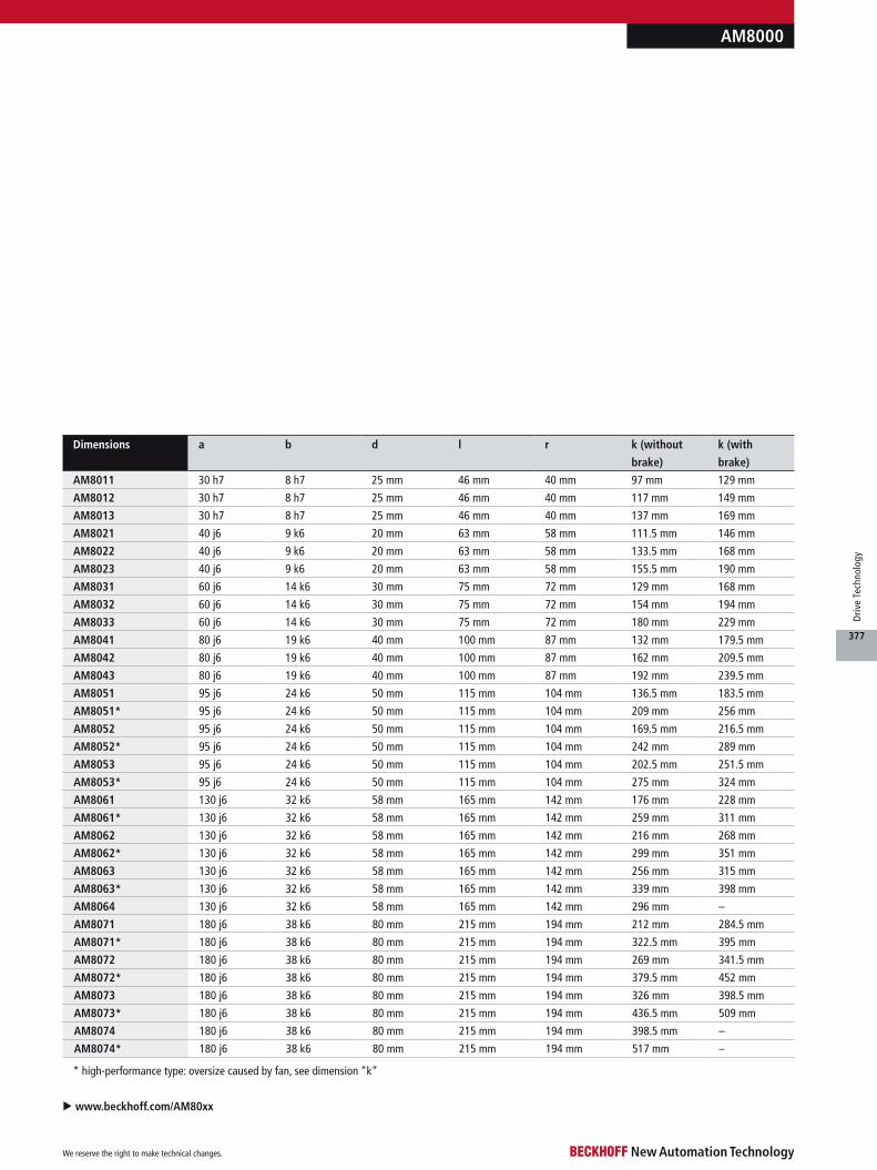
AM8000
u www.beckhoff.com/AM80xx
* high-performance type: oversize caused by fan, see dimension “k”
Dimensions a b d l r k (without
brake)
k (with
brake)
AM8011 30 h7 8 h7 25 mm 46 mm 40 mm 97 mm 129 mm
AM8012 30 h7 8 h7 25 mm 46 mm 40 mm 117 mm 149 mm
AM8013 30 h7 8 h7 25 mm 46 mm 40 mm 137 mm 169 mm
AM8021 40 j6 9 k6 20 mm 63 mm 58 mm 111.5 mm 146 mm
AM8022 40 j6 9 k6 20 mm 63 mm 58 mm 133.5 mm 168 mm
AM8023 40 j6 9 k6 20 mm 63 mm 58 mm 155.5 mm 190 mm
AM8031 60 j6 14 k6 30 mm 75 mm 72 mm 129 mm 168 mm
AM8032 60 j6 14 k6 30 mm 75 mm 72 mm 154 mm 194 mm
AM8033 60 j6 14 k6 30 mm 75 mm 72 mm 180 mm 229 mm
AM8041 80 j6 19 k6 40 mm 100 mm 87 mm 132 mm 179.5 mm
AM8042 80 j6 19 k6 40 mm 100 mm 87 mm 162 mm 209.5 mm
AM8043 80 j6 19 k6 40 mm 100 mm 87 mm 192 mm 239.5 mm
AM8051 95 j6 24 k6 50 mm 115 mm 104 mm 136.5 mm 183.5 mm
AM8051* 95 j6 24 k6 50 mm 115 mm 104 mm 209 mm 256 mm
AM8052 95 j6 24 k6 50 mm 115 mm 104 mm 169.5 mm 216.5 mm
AM8052* 95 j6 24 k6 50 mm 115 mm 104 mm 242 mm 289 mm
AM8053 95 j6 24 k6 50 mm 115 mm 104 mm 202.5 mm 251.5 mm
AM8053* 95 j6 24 k6 50 mm 115 mm 104 mm 275 mm 324 mm
AM8061 130 j6 32 k6 58 mm 165 mm 142 mm 176 mm 228 mm
AM8061* 130 j6 32 k6 58 mm 165 mm 142 mm 259 mm 311 mm
AM8062 130 j6 32 k6 58 mm 165 mm 142 mm 216 mm 268 mm
AM8062* 130 j6 32 k6 58 mm 165 mm 142 mm 299 mm 351 mm
AM8063 130 j6 32 k6 58 mm 165 mm 142 mm 256 mm 315 mm
AM8063* 130 j6 32 k6 58 mm 165 mm 142 mm 339 mm 398 mm
AM8064 130 j6 32 k6 58 mm 165 mm 142 mm 296 mm –
AM8071 180 j6 38 k6 80 mm 215 mm 194 mm 212 mm 284.5 mm
AM8071* 180 j6 38 k6 80 mm 215 mm 194 mm 322.5 mm 395 mm
AM8072 180 j6 38 k6 80 mm 215 mm 194 mm 269 mm 341.5 mm
AM8072* 180 j6 38 k6 80 mm 215 mm 194 mm 379.5 mm 452 mm
AM8073 180 j6 38 k6 80 mm 215 mm 194 mm 326 mm 398.5 mm
AM8073* 180 j6 38 k6 80 mm 215 mm 194 mm 436.5 mm 509 mm
AM8074 180 j6 38 k6 80 mm 215 mm 194 mm 398.5 mm –
AM8074* 180 j6 38 k6 80 mm 215 mm 194 mm 517 mm –
We reserve the right to make technical changes.
377
Driv
e Te
chno
logy

The AM8500 series extends the servomotor range by a complete series with increased rotor moment of inertia. Due to the modified rotor geometry it is increased, depending on the length, by 100 to 300 % com-pared to the AM8000 servomo-tors. The AM8500 series covers a wide performance range with four sizes and three lengths with standstill torques from 1.37 to 41 Nm. A particular highlight, as with all servomotors from the AM8000 series, is the One Cable Technology (OCT) that combines power and feedback system in the standard motor cable.
Due to the high rotor iner-tia, control of the AM8500 is simplified in areas in which a high external inertia has to be moved, e.g. CNC applications in machine tools and woodworking machines. The servomotors tend to vibrate less and are much easier to adjust to the applica-tion on the servo controller. Where the ratio of external to inherent inertia has previously required a gearbox, this can now be dispensed with in some cases. Typical areas of application for the AM8500 servomotors are in woodworking machines, printing machines and machine tools as
well as in film winders and feeding drive units.
In the forced cooling ver-sion the power density of the AM8500 motor series is thus increased further thanks to the external axial ventilation of the servomotors: the standstill torques can be increased by about 35 %; the rated torques at the rated speed even by up to 150 %. In this version the servo-motor series offers high torques even at high speeds. Cooling takes place with a 24 V DC fan, which is actuated independently of the motor. In the forced cool-ing version all further options
are available in accordance with the order data such as OCT or backlash-free permanent magnet holding brake. The forced cooling option is available for AM855x and AM856x.
Planetary gear units see page
Pre-assembled cables see page
Technical data AM85xx
Motor type permanent magnet-excited three-phase synchronous motor
Magnet material neodymium-iron-boron
Insulation class thermal class F (155 °C)
Design form flange-mounted according to IM B5, IM V1, IM V3
Protection class IP 54, IP 65 (shaft seal)
Cooling convection, permissible ambient temperature 40 °C, optionally: external axial ventilation
Coating/surface dark grey powder coating, similar to RAL7016
Temperature sensor integrated in stator winding
Connection method round plug connector, swivelling, angled
Life span L10h = 30,000 hrs for ball bearings
Approvals CE, UL
Feedback system absolute encoder single-turn and multi-turn, OCT, resolver, multi-turn 2-cable standard
AM8500 | Synchronous Servomotors with higher moment of inertia
350
386
AM8500
We reserve the right to make technical changes.
378
Driv
e Te
chno
logy
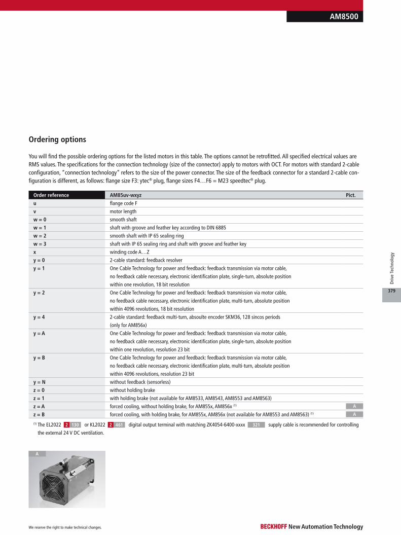
You will find the possible ordering options for the listed motors in this table. The options cannot be retrofitted. All specified electrical values are RMS values. The specifications for the connection technology (size of the connector) apply to motors with OCT. For motors with standard 2-cable configuration, “connection technology” refers to the size of the power connector. The size of the feedback connector for a standard 2-cable con-figuration is different, as follows: flange size F3: ytec® plug, flange sizes F4…F6 = M23 speedtec® plug.
AM8500
A
Ordering options
A
A
(1) The EL2022 or KL2022 digital output terminal with matching ZK4054-6400-xxxx supply cable is recommended for controlling
the external 24 V DC ventilation.
130 4612 2 321
Order reference AM85uv-wxyz Pict.
u flange code F
v motor length
w = 0 smooth shaft
w = 1 shaft with groove and feather key according to DIN 6885
w = 2 smooth shaft with IP 65 sealing ring
w = 3 shaft with IP 65 sealing ring and shaft with groove and feather key
x winding code A…Z
y = 0 2-cable standard: feedback resolver
y = 1 One Cable Technology for power and feedback: feedback transmission via motor cable,
no feedback cable necessary, electronic identification plate, single-turn, absolute position
within one revolution, 18 bit resolution
y = 2 One Cable Technology for power and feedback: feedback transmission via motor cable,
no feedback cable necessary, electronic identification plate, multi-turn, absolute position
within 4096 revolutions, 18 bit resolution
y = 4 2-cable standard: feedback multi-turn, absoulte encoder SKM36, 128 sincos periods
(only for AM856x)
y = A One Cable Technology for power and feedback: feedback transmission via motor cable,
no feedback cable necessary, electronic identification plate, single-turn, absolute position
within one revolution, resolution 23 bit
y = B One Cable Technology for power and feedback: feedback transmission via motor cable,
no feedback cable necessary, electronic identification plate, multi-turn, absolute position
within 4096 revolutions, resolution 23 bit
y = N without feedback (sensorless)
z = 0 without holding brake
z = 1 with holding brake (not available for AM8533, AM8543, AM8553 and AM8563)
z = A forced cooling, without holding brake, for AM855x, AM856x (1)
z = B forced cooling, with holding brake, for AM855x, AM856x (not available for AM8553 and AM8563) (1)
We reserve the right to make technical changes.
379
Driv
e Te
chno
logy

AM8500
Data for 400 V AC AM8532-wDyz AM8532-wEyz AM8532-wHyz
Standstill torque 2.38 Nm 2.37 Nm 2.37 Nm
Rated torque 2.30 Nm 2.20 Nm 1.85 Nm
Rated speed 3000 min-1 6000 min-1 9000 min-1
Rated power 0.72 kW 1.38 kW 1.74 kW
Standstill current 1.70 A 2.95 A 5.10 A
Rotor moment of inertia 2.05 kgcm²
Rotor moment of inertia (with brake) 2.15 kgcm²
Connection technology itec® plug
One Cable Technology (OCT) yes
AM8532 | Flange code F3, motor length 2
AM8533 | Flange code F3, motor length 3
Data for 400 V AC AM8541-wDyz AM8541-wEyz AM8541-wHyz
Standstill torque 2.37 Nm 2.45 Nm 2.40 Nm
Rated torque 2.30 Nm 2.31 Nm 2.10 Nm
Rated speed 3000 min-1 6000 min-1 8000 min-1
Rated power 0.72 kW 1.45 kW 1.76 kW
Standstill current 1.65 A 3.00 A 5.25 A
Rotor moment of inertia 4.62 kgcm²
Rotor moment of inertia (with brake) 5.27 kgcm²
Connection technology M23 speedtec® plug
One Cable Technology (OCT) yes
AM8541 | Flange code F4, motor length 1
Data for 400 V AC AM8533-wEy0 AM8533-wFy0 AM8533-wJy0
Standstill torque 3.20 Nm 3.22 Nm 3.22 Nm
Rated torque 2.98 Nm 2.70 Nm 2.30 Nm
Rated speed 3000 min-1 6000 min-1 9000 min-1
Rated power 0.94 kW 1.70 kW 2.17 kW
Standstill current 2.10 A 4.10 A 6.80 A
Rotor moment of inertia 2.44 kgcm²
Rotor moment of inertia (with brake) –
Connection technology itec® plug
One Cable Technology (OCT) yes
Data for 400 V AC AM8531-wCyz AM8531-wDyz AM8531-wFyz
Standstill torque 1.37 Nm 1.38 Nm 1.40 Nm
Rated torque 1.34 Nm 1.33 Nm 1.30 Nm
Rated speed 3000 min-1 6000 min-1 9000 min-1
Rated power 0.42 kW 0.84 kW 1.23 kW
Standstill current 1.00 A 1.95 A 3.20 A
Rotor moment of inertia 1.67 kgcm²
Rotor moment of inertia (with brake) 1.76 kgcm²
Connection technology itec® plug
One Cable Technology (OCT) yes
AM8531 | Flange code F3, motor length 1
We reserve the right to make technical changes.
380
Driv
e Te
chno
logy

AM8500
Data for 400 V AC AM8542-wEyz AM8542-wFyz AM8542-wJyz
Standstill torque 4.10 Nm
Rated torque 3.90 Nm 3.70 Nm 3.10 Nm
Rated speed 2500 min-1 5000 min-1 8000 min-1
Rated power 1.02 kW 1.94 kW 2.60 kW
Standstill current 2.15 A 4.10 A 6.90 A
Rotor moment of inertia 5.51 kgcm²
Rotor moment of inertia (with brake) 6.17 kgcm²
Connection technology M23 speedtec® plug
One Cable Technology (OCT) yes
AM8542 | Flange code F4, motor length 2
AM8543 | Flange code F4, motor length 3
Data for 400 V AC AM8551-wEyz AM8551-wGyz AM8551-wKyz
Standstill torque 4.80 Nm 4.90 Nm 4.90 Nm
Rated torque 4.60 Nm 4.40 Nm 3.90 Nm
Rated speed 2500 min-1 5000 min-1 8000 min-1
Rated power 1.20 kW 2.30 kW 3.27 kW
Standstill current 2.70 A 4.75 A 8.50 A
Rotor moment of inertia 8.75 kgcm²
Rotor moment of inertia (with brake) 9.41 kgcm²
Connection technology M23 speedtec® plug
One Cable Technology (OCT) yes
AM8551 | Flange code F5, motor length 1
AM8551 | Flange code F5, motor length 1, high-performance type with forced cooling
Data for 400 V AC AM8551-wFyz AM8551-wJyz AM8551-wLyz
Standstill torque 6.20 Nm 6.30 Nm 6.30 Nm
Rated torque 5.8 Nm 5.5 Nm 3.6 Nm
Rated speed 2500 min-1 4750 min-1 8000 min-1
Rated power 1.52 kW 2.74 kW 3.02 kW
Standstill current 3.50 A 5.80 A 11.1 A
Rotor moment of inertia 8.75 kgcm²
Rotor moment of inertia (with brake) 9.41 kgcm²
Connection technology M23 speedtec® plug
One Cable Technology (OCT) yes
Data for 400 V AC AM8543-wEy0 AM8543-wHy0 AM8543-wKy0
Standstill torque 5.65 Nm 5.65 Nm 5.60 Nm
Rated torque 5.30 Nm 4.90 Nm 4.10 Nm
Rated speed 2500 min-1 5000 min-1 8000 min-1
Rated power 1.39 kW 2.57 kW 3.43 kW
Standstill current 2.90 A 5.40 A 9.30 A
Rotor moment of inertia 6.41 kgcm²
Rotor moment of inertia (with brake) –
Connection technology M23 speedtec® plug
One Cable Technology (OCT) yes
We reserve the right to make technical changes.
381
Driv
e Te
chno
logy

AM8500
AM8553 | Flange code F5, motor length 3
AM8552 | Flange code F5, motor length 2, high-performance type with forced cooling
AM8553 | Flange code F5, motor length 3, high-performance type with forced cooling
Data for 400 V AC AM8552-wGyz AM8552-wKyz AM8552-wNyz
Standstill torque 10.7 Nm 10.7 Nm 9.6 Nm
Rated torque 9.7 Nm 9.1 Nm 5.4 Nm
Rated speed 2000 min-1 4000 min-1 6000 min-1
Rated power 2.03 kW 3.77 kW 4.08 kW
Standstill current 4.30 A 8.50 A 13.6 A
Rotor moment of inertia 10.6 kgcm²
Rotor moment of inertia (with brake) 11.2 kgcm²
Connection technology M23 speedtec® plug
One Cable Technology (OCT) yes
Data for 400 V AC AM8553-wJyA AM8553-wLyA AM8553-wPyA
Standstill torque 15.4 Nm 15.4 Nm 13.3 Nm
Rated torque 14.9 Nm 12.9 Nm 7.1 Nm
Rated speed 2000 min-1 4000 min-1 5000 min-1
Rated power 3.12 kW 5.41 kW 3.72 kW
Standstill current 6.40 A 11.9 A 18.6 A
Rotor moment of inertia 12.5 kgcm²
Rotor moment of inertia (with brake) –
Connection technology M23 speedtec® plug
One Cable Technology (OCT) yes
Data for 400 V AC AM8553-wGy0 AM8553-wKy0 AM8553-wNy0
Standstill torque 11.4 Nm
Rated torque 10.0 Nm 8.35 Nm 4.50 Nm
Rated speed 2000 min-1 4000 min-1 7000 min-1
Rated power 2.09 kW 3.50 kW 3.30 kW
Standstill current 4.70 A 8.80 A 15.6 A
Rotor moment of inertia 12.4 kgcm²
Rotor moment of inertia (with brake) –
Connection technology M23 speedtec® plug
One Cable Technology (OCT) yes
Data for 400 V AC AM8552-wFyz AM8552-wJyz AM8552-wLyz
Standstill torque 8.20 Nm
Rated torque 7.50 Nm 6.90 Nm 5.40 Nm
Rated speed 2000 min-1 4000 min-1 7300 min-1
Rated power 1.57 kW 2.89 kW 4.13 kW
Standstill current 3.30 A 6.30 A 11.3 A
Rotor moment of inertia 10.6 kgcm²
Rotor moment of inertia (with brake) 11.3 kgcm²
Connection technology M23 speedtec® plug
One Cable Technology (OCT) yes
AM8552 | Flange code F5, motor length 2
We reserve the right to make technical changes.
382
Driv
e Te
chno
logy
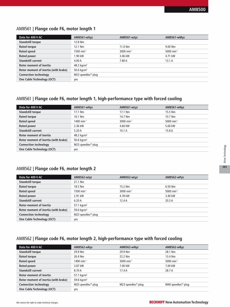
AM8500
Data for 400 V AC AM8561-wGyz AM8561-wJyz AM8561-wMyz
Standstill torque 12.8 Nm
Rated torque 12.1 Nm 11.0 Nm 9.00 Nm
Rated speed 1500 min-1 3000 min-1 5000 min-1
Rated power 1.90 kW 3.46 kW 4.71 kW
Standstill current 4.00 A 7.80 A 13.1 A
Rotor moment of inertia 48.2 kgcm²
Rotor moment of inertia (with brake) 50.6 kgcm²
Connection technology M23 speedtec® plug
One Cable Technology (OCT) yes
AM8561 | Flange code F6, motor length 1
AM8561 | Flange code F6, motor length 1, high-performance type with forced cooling
Data for 400 V AC AM8562-wJyz AM8562-wLyz AM8562-wPyz
Standstill torque 21.1 Nm
Rated torque 18.5 Nm 15.2 Nm 6.50 Nm
Rated speed 1500 min-1 3000 min-1 5000 min-1
Rated power 2.91 kW 4.78 kW 3.40 kW
Standstill current 6.20 A 12.4 A 20.3 A
Rotor moment of inertia 57.1 kgcm²
Rotor moment of inertia (with brake) 59.6 kgcm²
Connection technology M23 speedtec® plug
One Cable Technology (OCT) yes
AM8562 | Flange code F6, motor length 2
AM8562 | Flange code F6, motor length 2, high-performance type with forced cooling
Data for 400 V AC AM8562-wKyz AM8562-wNyz AM8562-wRyz
Standstill torque 29.9 Nm 29.9 Nm 28.1 Nm
Rated torque 26.4 Nm 22.2 Nm 13.4 Nm
Rated speed 1400 min-1 3000 min-1 5000 min-1
Rated power 3.87 kW 7.00 kW 7.00 kW
Standstill current 8.70 A 17.4 A 28.7 A
Rotor moment of inertia 57.1 kgcm²
Rotor moment of inertia (with brake) 59.6 kgcm²
Connection technology M23 speedtec® plug M23 speedtec® plug M40 speedtec® plug
One Cable Technology (OCT) yes
Data for 400 V AC AM8561-wHyz AM8561-wLyz AM8561-wNyz
Standstill torque 17.1 Nm 17.1 Nm 15.5 Nm
Rated torque 16.1 Nm 14.7 Nm 10.7 Nm
Rated speed 1400 min-1 3000 min-1 5000 min-1
Rated power 2.36 kW 4.60 kW 5.60 kW
Standstill current 5.20 A 10.1 A 15.8 A
Rotor moment of inertia 48.2 kgcm²
Rotor moment of inertia (with brake) 50.6 kgcm²
Connection technology M23 speedtec® plug
One Cable Technology (OCT) yes
We reserve the right to make technical changes.
383
Driv
e Te
chno
logy
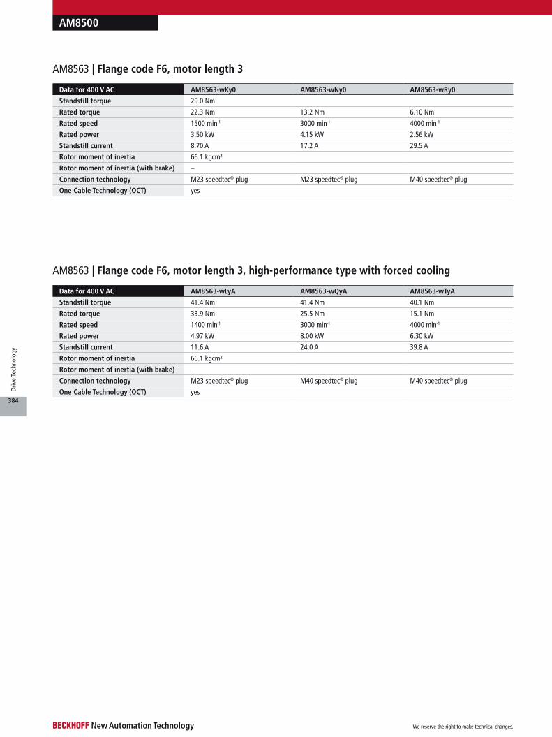
AM8500
AM8563 | Flange code F6, motor length 3, high-performance type with forced cooling
Data for 400 V AC AM8563-wLyA AM8563-wQyA AM8563-wTyA
Standstill torque 41.4 Nm 41.4 Nm 40.1 Nm
Rated torque 33.9 Nm 25.5 Nm 15.1 Nm
Rated speed 1400 min-1 3000 min-1 4000 min-1
Rated power 4.97 kW 8.00 kW 6.30 kW
Standstill current 11.6 A 24.0 A 39.8 A
Rotor moment of inertia 66.1 kgcm²
Rotor moment of inertia (with brake) –
Connection technology M23 speedtec® plug M40 speedtec® plug M40 speedtec® plug
One Cable Technology (OCT) yes
AM8563 | Flange code F6, motor length 3
Data for 400 V AC AM8563-wKy0 AM8563-wNy0 AM8563-wRy0
Standstill torque 29.0 Nm
Rated torque 22.3 Nm 13.2 Nm 6.10 Nm
Rated speed 1500 min-1 3000 min-1 4000 min-1
Rated power 3.50 kW 4.15 kW 2.56 kW
Standstill current 8.70 A 17.2 A 29.5 A
Rotor moment of inertia 66.1 kgcm²
Rotor moment of inertia (with brake) –
Connection technology M23 speedtec® plug M23 speedtec® plug M40 speedtec® plug
One Cable Technology (OCT) yes
We reserve the right to make technical changes.
384
Driv
e Te
chno
logy
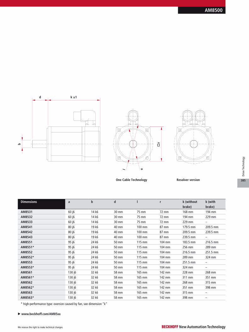
d k ±1
l a
One Cable Technology Resolver version
b r
u www.beckhoff.com/AM85xx
* high-performance type: oversize caused by fan, see dimension “k”
Dimensions a b d l r k (without
brake)
k (with
brake)
AM8531 60 j6 14 k6 30 mm 75 mm 72 mm 168 mm 194 mm
AM8532 60 j6 14 k6 30 mm 75 mm 72 mm 194 mm 229 mm
AM8533 60 j6 14 k6 30 mm 75 mm 72 mm 229 mm –
AM8541 80 j6 19 k6 40 mm 100 mm 87 mm 179.5 mm 209.5 mm
AM8542 80 j6 19 k6 40 mm 100 mm 87 mm 209.5 mm 239.5 mm
AM8543 80 j6 19 k6 40 mm 100 mm 87 mm 239.5 mm –
AM8551 95 j6 24 k6 50 mm 115 mm 104 mm 183.5 mm 216.5 mm
AM8551* 95 j6 24 k6 50 mm 115 mm 104 mm 256 mm 289 mm
AM8552 95 j6 24 k6 50 mm 115 mm 104 mm 216.5 mm 251.5 mm
AM8552* 95 j6 24 k6 50 mm 115 mm 104 mm 289 mm 324 mm
AM8553 95 j6 24 k6 50 mm 115 mm 104 mm 251.5 mm –
AM8553* 95 j6 24 k6 50 mm 115 mm 104 mm 324 mm –
AM8561 130 j6 32 k6 58 mm 165 mm 142 mm 228 mm 268 mm
AM8561* 130 j6 32 k6 58 mm 165 mm 142 mm 311 mm 351 mm
AM8562 130 j6 32 k6 58 mm 165 mm 142 mm 268 mm 315 mm
AM8562* 130 j6 32 k6 58 mm 165 mm 142 mm 351 mm 398 mm
AM8563 130 j6 32 k6 58 mm 165 mm 142 mm 315 mm –
AM8563* 130 j6 32 k6 58 mm 165 mm 142 mm 398 mm –
AM8500
We reserve the right to make technical changes.
385
Driv
e Te
chno
logy
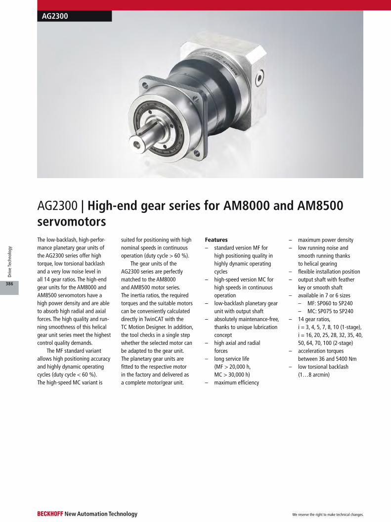
The low-backlash, high-perfor-mance planetary gear units of the AG2300 series offer high torque, low torsional backlash and a very low noise level in all 14 gear ratios. The high-end gear units for the AM8000 and AM8500 servomotors have a high power density and are able to absorb high radial and axial forces. The high quality and run-ning smoothness of this helical gear unit series meet the highest control quality demands.
The MF standard variant allows high positioning accuracy and highly dynamic operating cycles (duty cycle < 60 %). The high-speed MC variant is
suited for positioning with high nominal speeds in continuous operation (duty cycle > 60 %).
The gear units of the AG2300 series are perfectly matched to the AM8000 and AM8500 motor series. The inertia ratios, the required torques and the suitable motors can be conveniently calculated directly in TwinCAT with the TC Motion Designer. In addition, the tool checks in a single step whether the selected motor can be adapted to the gear unit. The planetary gear units are fitted to the respective motor in the factory and delivered as a complete motor/gear unit.
Features– standard version MF for
high positioning quality in highly dynamic operating cycles
– high-speed version MC for high speeds in continuous operation
– low-backlash planetary gear unit with output shaft
– absolutely maintenance-free, thanks to unique lubrication concept
– high axial and radial forces
– long service life (MF > 20,000 h, MC > 30,000 h)
– maximum efficiency
– maximum power density– low running noise and
smooth running thanks to helical gearing
– flexible installation position– output shaft with feather
key or smooth shaft– available in 7 or 6 sizes
– MF: SP060 to SP240– MC: SP075 to SP240
– 14 gear ratios, i = 3, 4, 5, 7, 8, 10 (1-stage), i = 16, 20, 25, 28, 32, 35, 40, 50, 64, 70, 100 (2-stage)
– acceleration torques between 36 and 5400 Nm
– low torsional backlash (1…8 arcmin)
AG2300 | High-end gear series for AM8000 and AM8500 servomotors
AG2300
We reserve the right to make technical changes.
386
Driv
e Te
chno
logy
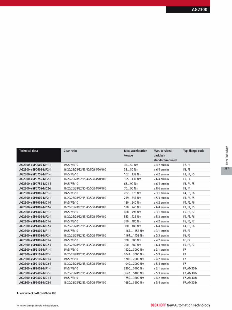
AG2300
u www.beckhoff.com/AG2300
Technical data Gear ratio Max. acceleration
torque
Max. torsional
backlash
standard/reduced
Typ. flange code
AG2300-+SP060S-MF1-i 3/4/5/7/8/10 36…50 Nm ≤ 4/2 arcmin F2, F3
AG2300-+SP060S-MF2-i 16/20/25/28/32/35/40/50/64/70/100 38…50 Nm ≤ 6/4 arcmin F2, F3
AG2300-+SP075S-MF1-i 3/4/5/7/8/10 102…132 Nm ≤ 4/2 arcmin F3, F4, F5
AG2300-+SP075S-MF2-i 16/20/25/28/32/35/40/50/64/70/100 105…132 Nm ≤ 6/4 arcmin F3, F4
AG2300-+SP075S-MC1-i 3/4/5/7/8/10 68…90 Nm ≤ 6/4 arcmin F3, F4, F5
AG2300-+SP075S-MC2-i 16/20/25/28/32/35/40/50/64/70/100 70…90 Nm ≤ 8/6 arcmin F3, F4
AG2300-+SP100S-MF1-i 3/4/5/7/8/10 282…378 Nm ≤ 3/1 arcmin F4, F5, F6
AG2300-+SP100S-MF2-i 16/20/25/28/32/35/40/50/64/70/100 259…347 Nm ≤ 5/3 arcmin F3, F4, F5
AG2300-+SP100S-MC1-i 3/4/5/7/8/10 180…240 Nm ≤ 4/2 arcmin F4, F5, F6
AG2300-+SP100S-MC2-i 16/20/25/28/32/35/40/50/64/70/100 180…240 Nm ≤ 6/4 arcmin F3, F4, F5
AG2300-+SP140S-MF1-i 3/4/5/7/8/10 468…792 Nm ≤ 3/1 arcmin F5, F6, F7
AG2300-+SP140S-MF2-i 16/20/25/28/32/35/40/50/64/70/100 583…726 Nm ≤ 5/3 arcmin F4, F5, F6
AG2300-+SP140S-MC1-i 3/4/5/7/8/10 310…480 Nm ≤ 4/2 arcmin F5, F6, F7
AG2300-+SP140S-MC2-i 16/20/25/28/32/35/40/50/64/70/100 380…480 Nm ≤ 6/4 arcmin F4, F5, F6
AG2300-+SP180S-MF1-i 3/4/5/7/8/10 1164…1452 Nm ≤ 3/1 arcmin F6, F7
AG2300-+SP180S-MF2-i 16/20/25/28/32/35/40/50/64/70/100 1164…1452 Nm ≤ 5/3 arcmin F5, F6
AG2300-+SP180S-MC1-i 3/4/5/7/8/10 700…880 Nm ≤ 4/2 arcmin F6, F7
AG2300-+SP180S-MC2-i 16/20/25/28/32/35/40/50/64/70/100 700…880 Nm ≤ 6/4 arcmin F5, F6, F7
AG2300-+SP210S-MF1-i 3/4/5/7/8/10 1920…3000 Nm ≤ 3/1 arcmin F7
AG2300-+SP210S-MF2-i 16/20/25/28/32/35/40/50/64/70/100 2043…3000 Nm ≤ 5/3 arcmin F7
AG2300-+SP210S-MC1-i 3/4/5/7/8/10 1200…2000 Nm ≤ 4/2 arcmin F7
AG2300-+SP210S-MC2-i 16/20/25/28/32/35/40/50/64/70/100 1040…2000 Nm ≤ 5/4 arcmin F7
AG2300-+SP240S-MF1-i 3/4/5/7/8/10 3300…5400 Nm ≤ 3/1 arcmin F7, AM308x
AG2300-+SP240S-MF2-i 16/20/25/28/32/35/40/50/64/70/100 3642…5400 Nm ≤ 5/3 arcmin F7, AM308x
AG2300-+SP240S-MC1-i 3/4/5/7/8/10 1750…3600 Nm ≤ 4/2 arcmin F7, AM308x
AG2300-+SP240S-MC2-i 16/20/25/28/32/35/40/50/64/70/100 1680…3600 Nm ≤ 5/4 arcmin F7, AM308x
We reserve the right to make technical changes.
387
Driv
e Te
chno
logy
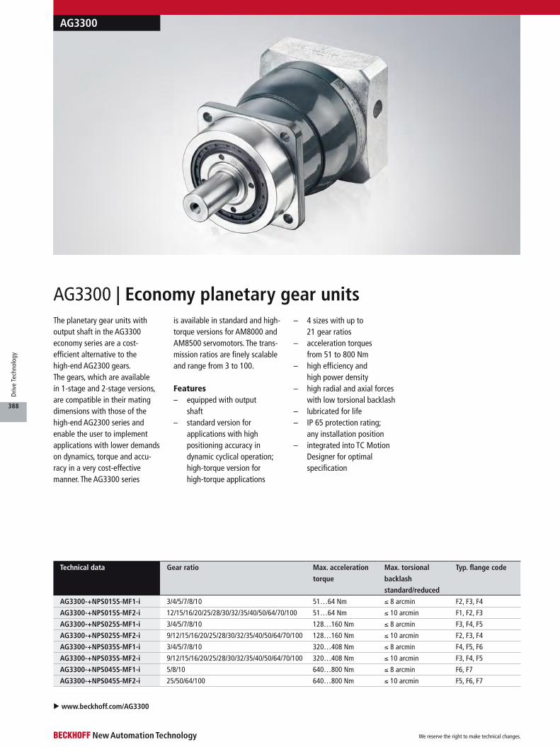
Technical data Gear ratio Max. acceleration
torque
Max. torsional
backlash
standard/reduced
Typ. flange code
AG3300-+NPS015S-MF1-i 3/4/5/7/8/10 51…64 Nm ≤ 8 arcmin F2, F3, F4
AG3300-+NPS015S-MF2-i 12/15/16/20/25/28/30/32/35/40/50/64/70/100 51…64 Nm ≤ 10 arcmin F1, F2, F3
AG3300-+NPS025S-MF1-i 3/4/5/7/8/10 128…160 Nm ≤ 8 arcmin F3, F4, F5
AG3300-+NPS025S-MF2-i 9/12/15/16/20/25/28/30/32/35/40/50/64/70/100 128…160 Nm ≤ 10 arcmin F2, F3, F4
AG3300-+NPS035S-MF1-i 3/4/5/7/8/10 320…408 Nm ≤ 8 arcmin F4, F5, F6
AG3300-+NPS035S-MF2-i 9/12/15/16/20/25/28/30/32/35/40/50/64/70/100 320…408 Nm ≤ 10 arcmin F3, F4, F5
AG3300-+NPS045S-MF1-i 5/8/10 640…800 Nm ≤ 8 arcmin F6, F7
AG3300-+NPS045S-MF2-i 25/50/64/100 640…800 Nm ≤ 10 arcmin F5, F6, F7
AG3300 | Economy planetary gear units
AG3300
u www.beckhoff.com/AG3300
The planetary gear units with output shaft in the AG3300 economy series are a cost- efficient alternative to the high-end AG2300 gears. The gears, which are available in 1-stage and 2-stage versions, are compatible in their mating dimensions with those of the high-end AG2300 series and enable the user to implement applications with lower demands on dynamics, torque and accu-racy in a very cost-effective manner. The AG3300 series
is available in standard and high-torque versions for AM8000 and AM8500 servomotors. The trans-mission ratios are finely scalable and range from 3 to 100.
Features– equipped with output
shaft– standard version for
applications with high positioning accuracy in dynamic cyclical operation; high-torque version for high-torque applications
– 4 sizes with up to 21 gear ratios
– acceleration torques from 51 to 800 Nm
– high efficiency and high power density
– high radial and axial forces with low torsional backlash
– lubricated for life– IP 65 protection rating;
any installation position– integrated into TC Motion
Designer for optimal specification
We reserve the right to make technical changes.
388
Driv
e Te
chno
logy
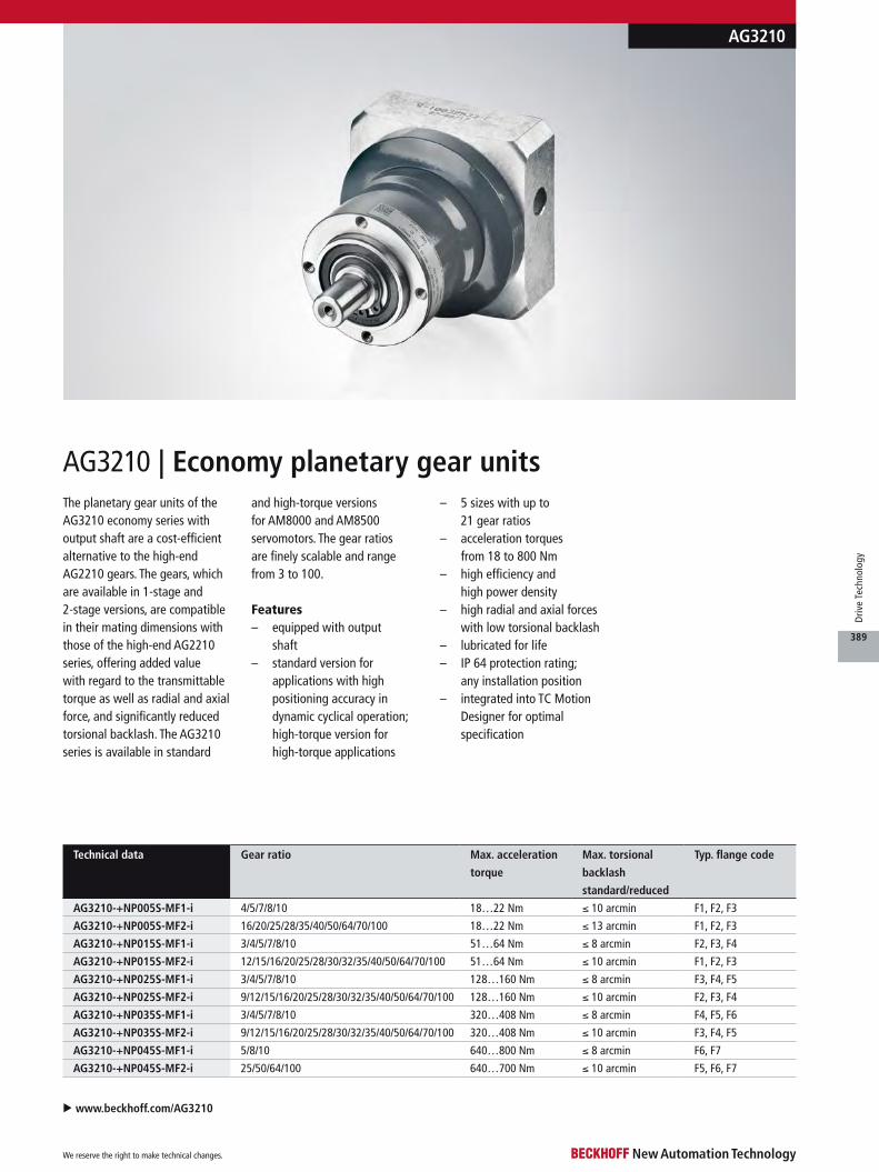
Technical data Gear ratio Max. acceleration
torque
Max. torsional
backlash
standard/reduced
Typ. flange code
AG3210-+NP005S-MF1-i 4/5/7/8/10 18…22 Nm ≤ 10 arcmin F1, F2, F3
AG3210-+NP005S-MF2-i 16/20/25/28/35/40/50/64/70/100 18…22 Nm ≤ 13 arcmin F1, F2, F3
AG3210-+NP015S-MF1-i 3/4/5/7/8/10 51…64 Nm ≤ 8 arcmin F2, F3, F4
AG3210-+NP015S-MF2-i 12/15/16/20/25/28/30/32/35/40/50/64/70/100 51…64 Nm ≤ 10 arcmin F1, F2, F3
AG3210-+NP025S-MF1-i 3/4/5/7/8/10 128…160 Nm ≤ 8 arcmin F3, F4, F5
AG3210-+NP025S-MF2-i 9/12/15/16/20/25/28/30/32/35/40/50/64/70/100 128…160 Nm ≤ 10 arcmin F2, F3, F4
AG3210-+NP035S-MF1-i 3/4/5/7/8/10 320…408 Nm ≤ 8 arcmin F4, F5, F6
AG3210-+NP035S-MF2-i 9/12/15/16/20/25/28/30/32/35/40/50/64/70/100 320…408 Nm ≤ 10 arcmin F3, F4, F5
AG3210-+NP045S-MF1-i 5/8/10 640…800 Nm ≤ 8 arcmin F6, F7
AG3210-+NP045S-MF2-i 25/50/64/100 640…700 Nm ≤ 10 arcmin F5, F6, F7
The planetary gear units of the AG3210 economy series with output shaft are a cost-efficient alternative to the high-end AG2210 gears. The gears, which are available in 1-stage and 2-stage versions, are compatible in their mating dimensions with those of the high-end AG2210 series, offering added value with regard to the transmittable torque as well as radial and axial force, and significantly reduced torsional backlash. The AG3210 series is available in standard
and high-torque versions for AM8000 and AM8500 servomotors. The gear ratios are finely scalable and range from 3 to 100.
Features– equipped with output
shaft – standard version for
applications with high positioning accuracy in dynamic cyclical operation; high-torque version for high-torque applications
– 5 sizes with up to 21 gear ratios
– acceleration torques from 18 to 800 Nm
– high efficiency and high power density
– high radial and axial forces with low torsional backlash
– lubricated for life– IP 64 protection rating;
any installation position– integrated into TC Motion
Designer for optimal specification
AG3210 | Economy planetary gear units
AG3210
u www.beckhoff.com/AG3210
We reserve the right to make technical changes.
389
Driv
e Te
chno
logy

AG2400
Technical data Gear ratio Max. acceleration
torque
Max. torsional
backlash
standard/reduced
Typ. flange code
AG2400-+TP004S-MF1-i 4/5/7/8/10 42…66 Nm ≤ 4/2 arcmin F2, F3, F4
AG2400-+TP004S-MF2-i 16/20/21/25/28/31/32/35/40/50/61/64/70/91/100 38…66 Nm ≤ 4/2 arcmin F1, F2, F3
AG2400-+TP010S-MF1-i 4/5/7/8/10 126…172 Nm ≤ 4/2 arcmin F3, F4, F5
AG2400-+TP010S-MF2-i 16/20/21/25/28/31/32/35/40/50/61/64/70/91/100 96…158 Nm ≤ 3/1 arcmin F2, F3, F4
AG2400-+TP025S-MF1-i 4/5/7/8/10 318…380 Nm ≤ 3/1 arcmin F4, F5, F6
AG2400-+TP025S-MF2-i 16/20/21/25/28/31/32/35/40/50/61/64/70/91/100 275…380 Nm ≤ 3/1 arcmin F3, F4, F5
AG2400-+TP050S-MF1-i 4/5/7/8/10 648…840 Nm ≤ 3/1 arcmin F5, F6, F7
AG2400-+TP050S-MF2-i 16/20/21/25/28/31/32/35/40/50/61/64/70/91/100 550…825 Nm ≤ 3/1 arcmin F4, F5, F6
AG2400-+TP110S-MF1-i 4/5/7/8/10 1680…1920 Nm ≤ 3/1 arcmin F6, F7
AG2400-+TP110S-MF2-i 16/20/21/25/28/31/32/35/40/50/61/64/70/91/100 1430…1760 Nm ≤ 3/1 arcmin F5, F6, F7
AG2400-+TP300S-MF1-i 5/7/8/10 2280…4200 Nm ≤ 3/1 arcmin F6, F7
AG2400-+TP300S-MF2-i 20/21/25/31/32/35/50/61/64/70/91/100 2800…3949 Nm ≤ 3/2 arcmin F6, F7
AG2400-+TP500S-MF1-i 5/7/8/10 4000…7200 Nm ≤ 3/1 arcmin F6, F7
AG2400-+TP500S-MF2-i 20/21/25/31/32/35/50/61/64/70/91/100 4800…6808 Nm ≤ 3/2 arcmin F6, F7
AG2400 | High-end planetary gear units with output flangeThe planetary gear units with output flange in the high-end AG2400 series absorb maximum radial and axial forces and transmit highest torques. High-quality gear tooth systems result in very low torsional backlash, making this gear series the ideal solution for dynamic and highly accurate positioning applica-tions. The low-noise gears of the AG2400 series are optimised for
the AM8xxx high-performance servomotors and meet the highest requirements regarding precision, dynamics and power density.
Features– equipped with output
flange– standard version for
applications with high positioning accuracy in
dynamic cyclical operation; high-torque version for high-torque applications
– 7 sizes with up to 20 gear ratios
– acceleration torques from 38 to 7200 Nm
– maximum efficiency– maximum radial and
axial forces with very low torsional backlash
– lubricated for life
– IP 65 protection rating; any installation position
– integrated into TC Motion Designer for optimal specification
u www.beckhoff.com/AG2400
We reserve the right to make technical changes.
390
Driv
e Te
chno
logy

The planetary gear units with output flange in the AG3400 economy series are a cost- efficient alternative to the high-end AG2400 gears. The gears, which are available in 1-stage and 2-stage versions, are compatible in their mating dimensions with those of the high-end AG2400 series and enable the user to implement applications with lower demands on dynamics, torque and accu-racy in a very cost-effective manner. The AG3400 series is
available in standard and high-torque versions for AM8000 and AM8500 servomotors. The gear ratios are finely scalable and range from 3 to 100.
Features– equipped with output
flange – standard version for
applications with high positioning accuracy in dynamic cyclical operation; high-torque version for high-torque applications
– 5 sizes with up to 21 gear ratios
– acceleration torques from 18 to 700 Nm
– high efficiency and high power density
– high radial and axial forces with low torsional backlash
– lubricated for life– IP 64 protection rating;
any installation position– integrated into TC Motion
Designer for optimal specification
AG3400 | Economy planetary gear units with output flange
Technical data Gear ratio Max. acceleration
torque
Max. torsional
backlash
standard/reduced
Typ. flange code
AG3400-+NPT005S-MF1-i 4/5/7/8/10 18…22 Nm ≤ 10 arcmin F1, F2, F3
AG3400-+NPT005S-MF2-i 16/20/25/28/35/40/50/64/70/100 18…22 Nm ≤ 13 arcmin F1, F2, F3
AG3400-+NPT015S-MF1-i 3/4/5/7/8/10 51…60 Nm ≤ 8 arcmin F2, F3, F4
AG3400-+NPT015S-MF2-i 12/15/16/20/25/28/30/32/35/40/50/64/70/100 51…60 Nm ≤ 10 arcmin F1, F2, F3
AG3400-+NPT025S-MF1-i 3/4/5/7/8/10 128…160 Nm ≤ 8 arcmin F3, F4, F5
AG3400-+NPT025S-MF2-i 9/12/15/16/20/25/28/30/32/35/40/50/64/70/100 128…160 Nm ≤ 10 arcmin F2, F3, F4
AG3400-+NPT035S-MF1-i 3/4/5/7/8/10 320…365 Nm ≤ 8 arcmin F4, F5, F6
AG3400-+NPT035S-MF2-i 9/12/15/16/20/25/28/30/32/35/40/50/64/70/100 320…365 Nm ≤ 10 arcmin F3, F4, F5
AG3400-+NPT045S-MF1-i 5/8/10 640…700 Nm ≤ 8 arcmin F6, F7
AG3400-+NPT045S-MF2-i 25/50/64/100 640…700 Nm ≤ 10 arcmin F5, F6, F7
AG3400
u www.beckhoff.com/AG3400
We reserve the right to make technical changes.
391
Driv
e Te
chno
logy
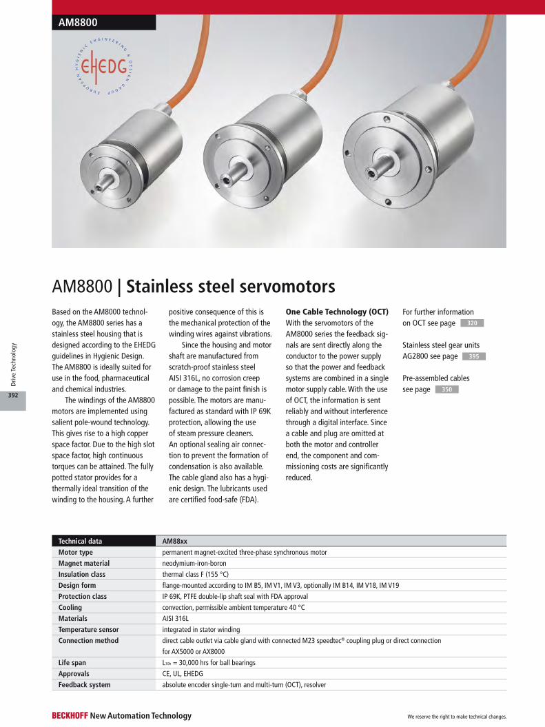
AM8800 | Stainless steel servomotorsBased on the AM8000 technol-ogy, the AM8800 series has a stainless steel housing that is designed according to the EHEDG guidelines in Hygienic Design. The AM8800 is ideally suited for use in the food, pharmaceutical and chemical industries.
The windings of the AM8800 motors are implemented using salient pole-wound technology. This gives rise to a high copper space factor. Due to the high slot space factor, high continuous torques can be attained. The fully potted stator provides for a thermally ideal transition of the winding to the housing. A further
positive consequence of this is the mechanical protection of the winding wires against vibrations.
Since the housing and motor shaft are manufactured from scratch-proof stainless steel AISI 316L, no corrosion creep or damage to the paint finish is possible. The motors are manu-factured as standard with IP 69K protection, allowing the use of steam pressure cleaners. An optional sealing air connec-tion to prevent the formation of condensation is also available. The cable gland also has a hygi-enic design. The lubricants used are certified food-safe (FDA).
One Cable Technology (OCT)With the servomotors of the AM8000 series the feedback sig-nals are sent directly along the conductor to the power supply so that the power and feedback systems are combined in a single motor supply cable. With the use of OCT, the information is sent reliably and without interference through a digital interface. Since a cable and plug are omitted at both the motor and controller end, the component and com-missioning costs are significantly reduced.
For further information on OCT see page
Stainless steel gear units AG2800 see page
Pre-assembled cables see page
320
350
395
Technical data AM88xx
Motor type permanent magnet-excited three-phase synchronous motor
Magnet material neodymium-iron-boron
Insulation class thermal class F (155 °C)
Design form flange-mounted according to IM B5, IM V1, IM V3, optionally IM B14, IM V18, IM V19
Protection class IP 69K, PTFE double-lip shaft seal with FDA approval
Cooling convection, permissible ambient temperature 40 °C
Materials AISI 316L
Temperature sensor integrated in stator winding
Connection method direct cable outlet via cable gland with connected M23 speedtec® coupling plug or direct connection
for AX5000 or AX8000
Life span L10h = 30,000 hrs for ball bearings
Approvals CE, UL, EHEDG
Feedback system absolute encoder single-turn and multi-turn (OCT), resolver
AM8800
We reserve the right to make technical changes.
392
Driv
e Te
chno
logy
AM8800
Order reference AM88uv-wxyz-caaa
u flange code
v motor length
w = 0 smooth shaft with sealing ring IP 69K
w = 1 shaft with groove and feather key according to DIN 6885 and sealing ring IP 69K
x winding code A…Z
y = 0 2-cable standard: feedback resolver
y = 1 One Cable Technology for power and feedback: feedback transmission via motor cable, no feedback cable
necessary, electronic identification plate, single-turn, absolute position within one revolution, 18 bit resolution
y = 2 One Cable Technology for power and feedback: feedback transmission via motor cable, no feedback cable
necessary, electronic identification plate, multi-turn, absolute position within 4096 revolutions, 18 bit resolution
z = 0 without holding brake
z = 2 without holding brake, with sealing air connection
z = 1 with holding brake
z = 3 with holding brake, with sealing air connection
c = 0 motor connection via M23 speedtec® plug, cable length definable via aaa (1)
c = 2 direct connection for AX5000 up to 25 A (X13+X14), cable length definable via aaa
c = 3 direct connection for AX8000 (X13), cable length definable via aaa
aaa length of the motor cable in decimetres
(1) For motor connection via an M23 speedtec® plug, a ZK4x00-80x3-xxxx motor supply cable must also be ordered in the required length.
Motor connections see page 350
Data for 400 V AC AM8831-wByz AM8832-wCyz AM8833-wDyz
Standstill torque 0.85 Nm 1.40 Nm 1.85 Nm
Rated torque 0.70 Nm 1.00 Nm 1.35 Nm
Rated speed 3000 min-1
Rated power 0.22 kW 0.31 kW 0.42 kW
Standstill current 0.65 A 1.00 A 1.25 A
Rotor moment of inertia 0.469 kgcm² 0.850 kgcm² 1.231 kgcm²
Rotor moment of inertia (with brake) 0.548 kgcm² 0.929 kgcm² 1.471 kgcm²
One Cable Technology (OCT) yes
AM883x | Flange code 3
Data for 400 V AC AM8841-wCyz AM8842-wDyz AM8843-wEyz
Standstill torque 1.60 Nm 2.60 Nm 3.50 Nm
Rated torque 1.30 Nm 1.90 Nm 2.75 Nm
Rated speed 3000 min-1 2500 min-1 2500 min-1
Rated power 0.41 kW 0.50 kW 0.72 kW
Standstill current 1.10 A 1.60 A 1.90 A
Rotor moment of inertia 1.115 kgcm² 2.006 kgcm² 2.898 kgcm²
Rotor moment of inertia (with brake) 1.765 kgcm² 2.656 kgcm² 3.548 kgcm²
One Cable Technology (OCT) yes
AM884x | Flange code 4
Ordering options
You will find the possible ordering options for the motors listed in this table. Please note: The options cannot be retrofitted. All electrical variables are RMS values.
We reserve the right to make technical changes.
393
Driv
e Te
chno
logy
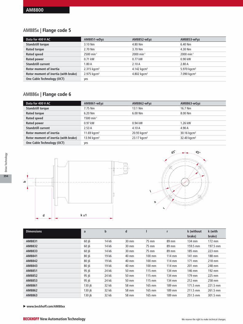
AM8800
b
d k ±1
l
a
r
45° 45°
u www.beckhoff.com/AM88xx
Dimensions a b d l r k (without
brake)
k (with
brake)
AM8831 60 j6 14 k6 30 mm 75 mm 89 mm 134 mm 172 mm
AM8832 60 j6 14 k6 30 mm 75 mm 89 mm 159.5 mm 197.5 mm
AM8833 60 j6 14 k6 30 mm 75 mm 89 mm 185 mm 223 mm
AM8841 80 j6 19 k6 40 mm 100 mm 114 mm 141 mm 188 mm
AM8842 80 j6 19 k6 40 mm 100 mm 114 mm 171 mm 218 mm
AM8843 80 j6 19 k6 40 mm 100 mm 114 mm 201 mm 248 mm
AM8851 95 j6 24 k6 50 mm 115 mm 134 mm 146 mm 192 mm
AM8852 95 j6 24 k6 50 mm 115 mm 134 mm 179 mm 225 mm
AM8853 95 j6 24 k6 50 mm 115 mm 134 mm 212 mm 258 mm
AM8861 130 j6 32 k6 58 mm 165 mm 189 mm 171.5 mm 221.5 mm
AM8862 130 j6 32 k6 58 mm 165 mm 189 mm 211.5 mm 261.5 mm
AM8863 130 j6 32 k6 58 mm 165 mm 189 mm 251.5 mm 301.5 mm
Data for 400 V AC AM8851-wDyz AM8852-wEyz AM8853-wFyz
Standstill torque 3.10 Nm 4.80 Nm 6.40 Nm
Rated torque 2.70 Nm 3.70 Nm 4.30 Nm
Rated speed 2500 min-1 2000 min-1 2000 min-1
Rated power 0.71 kW 0.77 kW 0.90 kW
Standstill current 1.80 A 2.10 A 2.80 A
Rotor moment of inertia 2.315 kgcm² 4.142 kgcm² 5.970 kgcm²
Rotor moment of inertia (with brake) 2.975 kgcm² 4.802 kgcm² 7.090 kgcm²
One Cable Technology (OCT) yes
AM885x | Flange code 5
Data for 400 V AC AM8861-wEyz AM8862-wFyz AM8863-wGyz
Standstill torque 7.75 Nm 13.1 Nm 16.7 Nm
Rated torque 6.20 Nm 6.00 Nm 8.00 Nm
Rated speed 1500 min-1
Rated power 0.97 kW 0.94 kW 1.26 kW
Standstill current 2.53 A 4.10 A 4.90 A
Rotor moment of inertia 11.69 kgcm² 20.93 kgcm² 30.16 kgcm²
Rotor moment of inertia (with brake) 13.94 kgcm² 23.17 kgcm² 32.40 kgcm²
One Cable Technology (OCT) yes
AM886x | Flange code 6
We reserve the right to make technical changes.
394
Driv
e Te
chno
logy
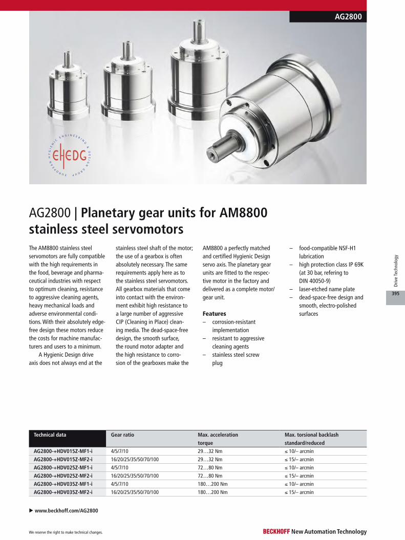
AG2800 | Planetary gear units for AM8800 stainless steel servomotorsThe AM8800 stainless steel servomotors are fully compatible with the high requirements in the food, beverage and pharma-ceutical industries with respect to optimum cleaning, resistance to aggressive cleaning agents, heavy mechanical loads and adverse environmental condi-tions. With their absolutely edge-free design these motors reduce the costs for machine manufac-turers and users to a minimum.
A Hygienic Design drive axis does not always end at the
stainless steel shaft of the motor; the use of a gearbox is often absolutely necessary. The same requirements apply here as to the stainless steel servomotors. All gearbox materials that come into contact with the environ-ment exhibit high resistance to a large number of aggressive CIP (Cleaning in Place) clean-ing media. The dead-space-free design, the smooth surface, the round motor adapter and the high resistance to corro-sion of the gearboxes make the
AM8800 a perfectly matched and certified Hygienic Design servo axis. The planetary gear units are fitted to the respec-tive motor in the factory and delivered as a complete motor/gear unit.
Features– corrosion-resistant
implementation– resistant to aggressive
cleaning agents– stainless steel screw
plug
– food-compatible NSF-H1 lubrication
– high protection class IP 69K (at 30 bar, refering to DIN 40050-9)
– laser-etched name plate– dead-space-free design and
smooth, electro-polished surfaces
AG2800
u www.beckhoff.com/AG2800
Technical data Gear ratio Max. acceleration
torque
Max. torsional backlash
standard/reduced
AG2800-+HDV015Z-MF1-i 4/5/7/10 29…32 Nm ≤ 10/– arcmin
AG2800-+HDV015Z-MF2-i 16/20/25/35/50/70/100 29…32 Nm ≤ 15/– arcmin
AG2800-+HDV025Z-MF1-i 4/5/7/10 72…80 Nm ≤ 10/– arcmin
AG2800-+HDV025Z-MF2-i 16/20/25/35/50/70/100 72…80 Nm ≤ 15/– arcmin
AG2800-+HDV035Z-MF1-i 4/5/7/10 180…200 Nm ≤ 10/– arcmin
AG2800-+HDV035Z-MF2-i 16/20/25/35/50/70/100 180…200 Nm ≤ 15/– arcmin
We reserve the right to make technical changes.
395
Driv
e Te
chno
logy
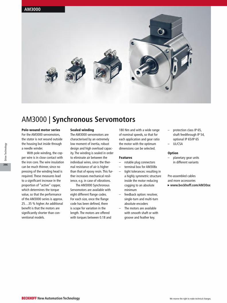
AM3000 | Synchronous Servomotors
AM3000
Pre-assembled cables and more accessories
www.beckhoff.com/AM30xx
Pole-wound motor seriesFor the AM3000 servomotors, the stator is not wound outside the housing but inside through a needle winder.
With pole winding, the cop-per wire is in close contact with the iron core. The wire insulation can be much thinner, since no pressing of the winding head is required. These measures lead to a significant increase in the proportion of “active” copper, which determines the torque value, so that the performance of the AM3000 series is approx. 25…35 % higher. An additional benefit is that the motors are significantly shorter than con-ventional models.
Sealed windingThe AM3000 servomotors are characterised by an extremely low moment of inertia, robust design and high overload capac-ity. The winding is sealed in order to eliminate air between the individual wires, since the ther-mal resistance of air is higher than that of epoxy resin. This fur-ther increases mechanical resil-ience, e.g. in case of vibrations.
The AM3000 Synchronous Servomotors are available with eight different flange codes. For each size, once the flange code has been defined, there is scope for variation in the length. The motors are offered with torques between 0.18 and
180 Nm and with a wide range of nominal speeds, so that for each application and gear ratio the motor with the optimum dimensions can be selected.
Features– rotable plug connectors– terminal box for AM308x– tight tolerances: resulting in
a highly symmetric structure inside the motor reducing cogging to an absolute minimum
– feedback option: resolver, single-turn and multi-turn absolute encoders
– The motors are available with smooth shaft or with groove and feather key.
– protection class IP 65, shaft feedthrough IP 54, optional IP 65/IP 65
– UL/CSA
Option– planetary gear units
in different variants
We reserve the right to make technical changes.
396
Driv
e Te
chno
logy

AM3000
The table is continued on the next page.
AM3000
AM30uv-wxyz-000a Stand-
still
torque
Stand-
still
current
Rated speed at rated supply voltage Rotor moment of inertia Weight
(without
brake)
Weight
(with
brake)
230 V AC 400 V AC 480 V AC (without
brake)
(with
brake)
AM3011-wByz-000a 0.18 Nm 1.16 A 8000 min-1 – – 0.017 kg cm² 0.020 kg cm² 0.35 kg 0.55 kg
AM3012-wCyz-000a 0.31 Nm 1.51 A 8000 min-1 – – 0.031 kg cm² 0.034 kg cm² 0.49 kg 0.69 kg
AM3013-wCyz-000a 0.41 Nm 1.48 A 8000 min-1 – – 0.045 kg cm² 0.048 kg cm² 0.63 kg 0.83 kg
AM3013-wDyz-000a 0.40 Nm 2.40 A – – – 0.045 kg cm² 0.048 kg cm² 0.63 kg 0.83 kg
AM3021-wCyz-000a 0.48 Nm 1.58 A 8000 min-1 – – 0.107 kg cm² 0.118 kg cm² 0.82 kg 1.09 kg
AM3022-wCyz-000a 0.84 Nm 1.39 A 3500 min-1 8000 min-1 8000 min-1 0.161 kg cm² 0.172 kg cm² 1.10 kg 1.37 kg
AM3022-wEyz-000a 0.87 Nm 2.73 A 8000 min-1 – – 0.161 kg cm² 0.172 kg cm² 1.10 kg 1.37 kg
AM3023-wCyz-000a 1.13 Nm 1.41 A 2500 min-1 5500 min-1 7000 min-1 0.216 kg cm² 0.227 kg cm² 1.38 kg 1.65 kg
AM3023-wDyz-000a 1.16 Nm 2.19 A 5000 min-1 8000 min-1 8000 min-1 0.216 kg cm² 0.227 kg cm² 1.38 kg 1.65 kg
AM3024-wCyz-000a 1.38 Nm 1.42 A 2000 min-1 4500 min-1 5500 min-1 0.270 kg cm² 0.281 kg cm² 1.66 kg 1.93 kg
AM3024-wDyz-000a 1.41 Nm 2.21 A 4000 min-1 8000 min-1 8000 min-1 0.270 kg cm² 0.281 kg cm² 1.66 kg 1.93 kg
AM3031-wCyz-0000 1.15 Nm 1.37 A 2500 min-1 5000 min-1 6000 min-1 0.330 kg cm² 0.341 kg cm² 1.55 kg 1.90 kg
AM3031-wEyz-0000 1.20 Nm 2.99 A 6000 min-1 – – 0.330 kg cm² 0.341 kg cm² 1.55 kg 1.90 kg
AM3032-wCyz-0000 2.00 Nm 1.44 A 1500 min-1 3000 min-1 3500 min-1 0.590 kg cm² 0.601 kg cm² 2.23 kg 2.58 kg
AM3032-wDyz-0000 2.04 Nm 2.23 A 2500 min-1 5500 min-1 6000 min-1 0.590 kg cm² 0.601 kg cm² 2.23 kg 2.58 kg
AM3032-wHyz-0000 2.10 Nm 5.50 A 7000 min-1 – – 0.590 kg cm² 0.601 kg cm² 2.23 kg 2.58 kg
AM3033-wCyz-0000 2.71 Nm 1.47 A 1000 min-1 2000 min-1 2500 min-1 0.850 kg cm² 0.861 kg cm² 2.90 kg 3.25 kg
AM3033-wEyz-0000 2.79 Nm 2.58 A 2000 min-1 4500 min-1 5000 min-1 0.850 kg cm² 0.861 kg cm² 2.90 kg 3.25 kg
AM3041-wCyz-0000 1.95 Nm 1.46 A 1200 min-1 3000 min-1 3500 min-1 0.810 kg cm² 0.878 kg cm² 2.44 kg 3.07 kg
AM3041-wEyz-0000 2.02 Nm 2.85 A 3000 min-1 6000 min-1 6000 min-1 0.810 kg cm² 0.878 kg cm² 2.44 kg 3.07 kg
AM3041-wHyz-0000 2.06 Nm 5.60 A 6000 min-1 6000 min-1 6000 min-1 0.810 kg cm² 0.878 kg cm² 2.44 kg 3.07 kg
AM3042-wCyz-0000 3.35 Nm 1.40 A – 1500 min-1 2000 min-1 1.450 kg cm² 1.518 kg cm² 3.39 kg 4.02 kg
AM3042-wEyz-0000 3.42 Nm 2.74 A 1800 min-1 3500 min-1 4000 min-1 1.450 kg cm² 1.518 kg cm² 3.39 kg 4.02 kg
AM3042-wGyz-0000 3.53 Nm 4.80 A 3500 min-1 6000 min-1 6000 min-1 1.450 kg cm² 1.518 kg cm² 3.39 kg 4.02 kg
AM3043-wEyz-0000 4.70 Nm 2.76 A 1500 min-1 2500 min-1 3000 min-1 2.090 kg cm² 2.158 kg cm² 4.35 kg 4.98 kg
AM3043-wGyz-0000 4.80 Nm 4.87 A 2500 min-1 5000 min-1 6000 min-1 2.090 kg cm² 2.158 kg cm² 4.35 kg 4.98 kg
AM3043-wHyz-0000 4.82 Nm 5.40 A 3000 min-1 6000 min-1 – 2.090 kg cm² 2.158 kg cm² 4.35 kg 4.98 kg
AM3044-wEyz-0000 5.76 Nm 2.90 A 1200 min-1 2000 min-1 2500 min-1 2.730 kg cm² 2.798 kg cm² 5.30 kg 5.93 kg
AM3044-wGyz-0000 5.88 Nm 5.00 A 2000 min-1 4000 min-1 5000 min-1 2.730 kg cm² 2.798 kg cm² 5.30 kg 5.93 kg
AM3044-wHyz-0000 5.89 Nm 5.60 A 2500 min-1 5000 min-1 6000 min-1 2.730 kg cm² 2.798 kg cm² 5.30 kg 5.93 kg
AM3044-wJyz-0000 6.00 Nm 8.80 A 4000 min-1 6000 min-1 6000 min-1 2.730 kg cm² 2.798 kg cm² 5.30 kg 5.93 kg
AM3051-wEyz-0000 4.70 Nm 2.75 A 1200 min-1 2500 min-1 3000 min-1 3.420 kg cm² 3.593 kg cm² 4.20 kg 5.30 kg
AM3051-wGyz-0000 4.75 Nm 4.84 A 2500 min-1 5000 min-1 6000 min-1 3.420 kg cm² 3.593 kg cm² 4.20 kg 5.30 kg
AM3051-wHyz-0000 4.79 Nm 6.00 A 3000 min-1 6000 min-1 6000 min-1 3.420 kg cm² 3.593 kg cm² 4.20 kg 5.30 kg
AM3052-wGyz-0000 8.43 Nm 4.72 A 1500 min-1 2500 min-1 3000 min-1 6.220 kg cm² 6.393 kg cm² 5.80 kg 6.90 kg
AM3052-wHyz-0000 8.48 Nm 5.90 A 1800 min-1 3500 min-1 4000 min-1 6.220 kg cm² 6.393 kg cm² 5.80 kg 6.90 kg
AM3052-wKyz-0000 8.60 Nm 9.30 A 3000 min-1 5500 min-1 6000 min-1 6.220 kg cm² 6.393 kg cm² 5.80 kg 6.90 kg
AM3053-wGyz-0000 11.37 Nm 4.77 A 1000 min-1 2000 min-1 2400 min-1 9.120 kg cm² 9.293 kg cm² 7.40 kg 8.50 kg
AM3053-wHyz-0000 11.51 Nm 6.60 A – 3000 min-1 3500 min-1 9.120 kg cm² 9.293 kg cm² 7.40 kg 8.50 kg
AM3053-wKyz-0000 11.60 Nm 9.40 A 2000 min-1 4000 min-1 4500 min-1 9.120 kg cm² 9.293 kg cm² 7.40 kg 8.50 kg
AM3054-wGyz-0000 14.30 Nm 5.00 A – 1500 min-1 2000 min-1 11.92 kg cm² 12.093 kg cm² 9.00 kg 10.1 kg
AM3054-wHyz-0000 14.90 Nm 5.50 A 1000 min-1 1800 min-1 2000 min-1 11.92 kg cm² 12.093 kg cm² 9.00 kg 10.1 kg
AM3054-wKyz-0000 14.40 Nm 9.70 A 1800 min-1 3500 min-1 4000 min-1 11.92 kg cm² 12.093 kg cm² 9.00 kg 10.1 kg
AM3054-wLyz-0000 14.10 Nm 12.50 A 2500 min-1 4500 min-1 – 11.92 kg cm² 12.093 kg cm² 9.00 kg 10.1 kg
AM3062-wGyz-0000 11.90 Nm 4.90 A – 1800 min-1 2000 min-1 16.90 kg cm² 17.51 kg cm² 8.90 kg 10.9 kg
AM3062-wHyz-0000 11.90 Nm 5.40 A 1000 min-1 2000 min-1 2400 min-1 16.90 kg cm² 17.51 kg cm² 8.90 kg 10.9 kg
AM3062-wKyz-0000 12.20 Nm 9.60 A 2000 min-1 3500 min-1 4500 min-1 16.90 kg cm² 17.51 kg cm² 8.90 kg 10.9 kg
AM3062-wMyz-0000 12.20 Nm 13.40 A 3000 min-1 6000 min-1 6000 min-1 16.90 kg cm² 17.51 kg cm² 8.90 kg 10.9 kg
AM3063-wKyz-0000 16.80 Nm 9.90 A 1500 min-1 3000 min-1 3500 min-1 24.20 kg cm² 24.81 kg cm² 11.1 kg 13.1 kg
AM3063-wMyz-0000 17.00 Nm 13.80 A 2000 min-1 4000 min-1 4500 min-1 24.20 kg cm² 24.81 kg cm² 11.1 kg 13.1 kg
AM3063-wNyz-0000 17.00 Nm 17.40 A 3000 min-1 5000 min-1 6000 min-1 24.20 kg cm² 24.81 kg cm² 11.1 kg 13.1 kg
We reserve the right to make technical changes.
397
Driv
e Te
chno
logy

u: flange code
v: motor length
Option w = 0: smooth shaft (preferred type)
w = 1: shaft with groove and feather key according to DIN 6885
w = 2: shaft with IP 65 sealing ring and smooth shaft
w = 3: shaft with IP 65 sealing ring and shaft with groove and feather key
Option x = winding code A…T
Option y = 0: resolver, 2-pole
y = 1: single-turn absolute encoder, EnDat 2.1
absolute position within one revolution, electronic identification plate
AM302x…AM304x: 512 sine periods per revolution
AM305x…AM308x: 2048 sine periods per revolution
y = 2: multi-turn absolute encoder, EnDat 2.1
absolute position within 4096 revolutions, electronic identification plate
AM302x…AM304x: 512 sine periods per revolution
AM305x…AM308x: 2048 sine periods per revolution
y = 3: single-turn absolute encoder, BiSS
absolute position within one revolution, electronic identification plate
AM302x…AM308x: 2048 sine periods per revolution
y = 4: multi-turn absolute encoder, BiSS
absolute position within 4096 revolutions, electronic identification plate
AM302x…AM308x: 2048 sine periods per revolution
Option z = 0: without holding brake
z = 1: with holding brake
Option a = 0: rotatable angular connectors for motor and feedback cable (only for AM302x up to AM307x)
a = 1: supply cable 0.5 m with non-detachable plugs (only for AM301x/AM302x), only for resolver
a = 3: vertical connectors for motor and feedback cables (only for AM302x up to AM307x)
a = 5: yTec plug (only for AM301x)
a = 6: motor connection via terminal box (only for AM308x)
With the exception of the shaft seal, the options cannot be installed in the field.
Options such as shaft seal, holding brake, absolute encoder can lead to a reduction of the nominal rating.
AM3000
AM30uv-wxyz-000a Stand-
still
torque
Stand-
still
current
Rated speed at rated supply voltage Rotor moment of inertia Weight
(without
brake)
Weight
(with
brake)
230 V AC 400 V AC 480 V AC (without
brake)
(with
brake)
AM3063-wHyz-0000 16.60 Nm 5.60 A – 1500 min-1 1800 min-1 31.60 kg cm² 32.21 kg cm² 13.3 kg 15.3 kg
AM3064-wKyz-0000 20.80 Nm 9.20 A 1200 min-1 2000 min-1 2500 min-1 31.60 kg cm² 32.21 kg cm² 13.3 kg 15.3 kg
AM3064-wLyz-0000 21.00 Nm 12.80 A 1500 min-1 3000 min-1 3500 min-1 31.60 kg cm² 32.21 kg cm² 13.3 kg 15.3 kg
AM3064-wPyz-0000 20.40 Nm 18.60 A 2500 min-1 4500 min-1 5500 min-1 31.60 kg cm² 32.21 kg cm² 13.3 kg 15.3 kg
AM3065-wKyz-0000 24.80 Nm 9.80 A 1000 min-1 2000 min-1 2200 min-1 40.00 kg cm² 40.61 kg cm² 15.4 kg 17.4 kg
AM3065-wMyz-0000 25.00 Nm 13.60 A 1500 min-1 2500 min-1 3000 min-1 40.00 kg cm² 40.61 kg cm² 15.4 kg 17.4 kg
AM3065-wNyz-0000 24.30 Nm 17.80 A 2000 min-1 3500 min-1 4000 min-1 40.00 kg cm² 40.61 kg cm² 15.4 kg 17.4 kg
AM3065-wPyz-0000 24.50 Nm 19.80 A 2400 min-1 4000 min-1 5000 min-1 40.00 kg cm² 40.61 kg cm² 15.4 kg 17.4 kg
AM3072-wKyz-0000 29.70 Nm 9.30 A – 1500 min-1 1800 min-1 64.50 kg cm² 66.14 kg cm² 19.7 kg 21.8 kg
AM3072-wMyz-0000 30.00 Nm 13.00 A – 2000 min-1 2500 min-1 64.50 kg cm² 66.14 kg cm² 19.7 kg 21.8 kg
AM3072-wPyz-0000 29.40 Nm 18.70 A 1800 min-1 3000 min-1 3500 min-1 64.50 kg cm² 66.14 kg cm² 19.7 kg 21.8 kg
AM3072-wQyz-0000 29.70 Nm 20.90 A – 3500 min-1 4000 min-1 64.50 kg cm² 66.14 kg cm² 19.7 kg 21.8 kg
AM3073-wMyz-0000 42.00 Nm 13.60 A – 1500 min-1 1800 min-1 92.10 kg cm² 93.74 kg cm² 26.7 kg 28.8 kg
AM3073-wPyz-0000 41.60 Nm 19.50 A 1300 min-1 2400 min-1 2800 min-1 92.10 kg cm² 93.74 kg cm² 26.7 kg 28.8 kg
AM3073-wQyz-0000 41.60 Nm 24.60 A – 3000 min-1 3500 min-1 92.10 kg cm² 93.74 kg cm² 26.7 kg 28.8 kg
AM3074-wLyz-0000 53.00 Nm 12.90 A – 1200 min-1 1400 min-1 119.7 kg cm² 121.34 kg cm² 33.6 kg 35.7 kg
AM3074-wPyz-0000 52.50 Nm 18.50 A – 1800 min-1 2000 min-1 119.7 kg cm² 121.34 kg cm² 33.6 kg 35.7 kg
AM3074-wQyz-0000 51.90 Nm 26.20 A – 2500 min-1 3000 min-1 119.7 kg cm² 121.34 kg cm² 33.0 kg 35.7 kg
AM3082-wTyz-0006 75.00 Nm 48.00 A – 2500 min-1 3000 min-1 172.0 kg cm² 177.00 kg cm² 65.0 kg 73.0 kg
AM3083-wTyz-0006 130.0 Nm 62.00 A – 2200 min-1 2500 min-1 334.0 kg cm² 339.00 kg cm² 85.0 kg 93.0 kg
AM3084-wTyz-0006 180.0 Nm 67.00 A – 1800 min-1 2000 min-1 495.0 kg cm² 500.00 kg cm² 105 kg 113 kg
We reserve the right to make technical changes.
398
Driv
e Te
chno
logy

a b
kd
a b
kd
hier nur vorsichtshalber aufbe-wahrt....
l
r
Dimensions a b d k (resolver)
(without
brake)
k (resolver)
(with brake)
k (encoder)
(without
brake)
k (encoder)
(with brake)
l r
AM3011 30 mm 8 mm 25 mm 69.6 mm 106.6 mm 79.1 mm 116.1 mm 46 mm 40 mm
AM3012 30 mm 8 mm 25 mm 88.6 mm 125.6 mm 98.1 mm 135.1 mm 46 mm 40 mm
AM3013 30 mm 8 mm 25 mm 107.6 mm 144.6 mm 117.1 mm 154.1 mm 46 mm 40 mm
AM3021 40 mm 9 mm 20 mm 95.4 mm 129.5 mm 95.4 mm 129.5 mm 63 mm 58 mm
AM3022 40 mm 9 mm 20 mm 114.4 mm 148.5 mm 114.4 mm 148.5 mm 63 mm 58 mm
AM3023 40 mm 9 mm 20 mm 133.4 mm 167.5 mm 133.4 mm 167.5 mm 63 mm 58 mm
AM3024 40 mm 9 mm 20 mm 152.4 mm 186.5 mm 152.4 mm 186.5 mm 63 mm 58 mm
AM3031 60 mm 14 mm 30 mm 109.8 mm 141.3 mm 109.8 mm 141.3 mm 75 mm 70 mm
AM3032 60 mm 14 mm 30 mm 140.8 mm 172.3 mm 140.8 mm 172.3 mm 75 mm 70 mm
AM3033 60 mm 14 mm 30 mm 171.8 mm 203.3 mm 171.8 mm 203.3 mm 75 mm 70 mm
AM3041 80 mm 19 mm 40 mm 118.8 mm 152.3 mm 118.8 mm 152.3 mm 100 mm 84 mm
AM3042 80 mm 19 mm 40 mm 147.8 mm 181.3 mm 147.8 mm 181.3 mm 100 mm 84 mm
AM3043 80 mm 19 mm 40 mm 176.8 mm 210.3 mm 176.8 mm 210.3 mm 100 mm 84 mm
AM3044 80 mm 19 mm 40 mm 205.8 mm 239.3 mm 205.8 mm 239.3 mm 100 mm 84 mm
AM3051 110 mm 24 mm 50 mm 127.5 mm 172.5 mm 146.0 mm 189.0 mm 130 mm 108 mm
AM3052 110 mm 24 mm 50 mm 158.5 mm 203.5 mm 177.0 mm 220.0 mm 130 mm 108 mm
AM3053 110 mm 24 mm 50 mm 189.5 mm 234.5 mm 208.0 mm 251.0 mm 130 mm 108 mm
AM3054 110 mm 24 mm 50 mm 220.5 mm 265.5 mm 239.0 mm 282.0 mm 130 mm 108 mm
AM3062 130 mm 32 mm 58 mm 153.7 mm 200.7 mm 172.2 mm 219.7 mm 165 mm 138 mm
AM3063 130 mm 32 mm 58 mm 178.7 mm 225.7 mm 197.2 mm 244.7 mm 165 mm 138 mm
AM3064 130 mm 32 mm 58 mm 203.7 mm 250.7 mm 222.2 mm 269.7 mm 165 mm 138 mm
AM3065 130 mm 32 mm 58 mm 228.7 mm 275.7 mm 247.2 mm 294.7 mm 165 mm 138 mm
AM3072 180 mm 38 mm 80 mm 192.5 mm 234.5 mm 201.7 mm 253.7 mm 215 mm 188 mm
AM3073 180 mm 38 mm 80 mm 226.5 mm 268.5 mm 235.7 mm 287.3 mm 215 mm 188 mm
AM3074 180 mm 38 mm 80 mm 260.5 mm 302.5 mm 269.7 mm 321.3 mm 215 mm 188 mm
AM3082 250 mm 48 mm 110 mm 263.4 mm 329.4 mm 263.4 mm 329.4 mm 300 mm 260 mm
AM3083 250 mm 48 mm 110 mm 343.9 mm 410.0 mm 343.9 mm 410.0 mm 300 mm 260 mm
AM3084 250 mm 48 mm 110 mm 424.4 mm 490.4 mm 424.4 mm 490.4 mm 300 mm 260 mm
AM3000AM3000
u www.beckhoff.com/AM30xx
We reserve the right to make technical changes.
399
Driv
e Te
chno
logy

ALxxxx | Linear Servomotors
Primary section:Coil unit
Secondary section:Magnet plate (sealed)
u www.beckhoff.com/Linear-motors
We reserve the right to make technical changes.
400
Driv
e Te
chno
logy
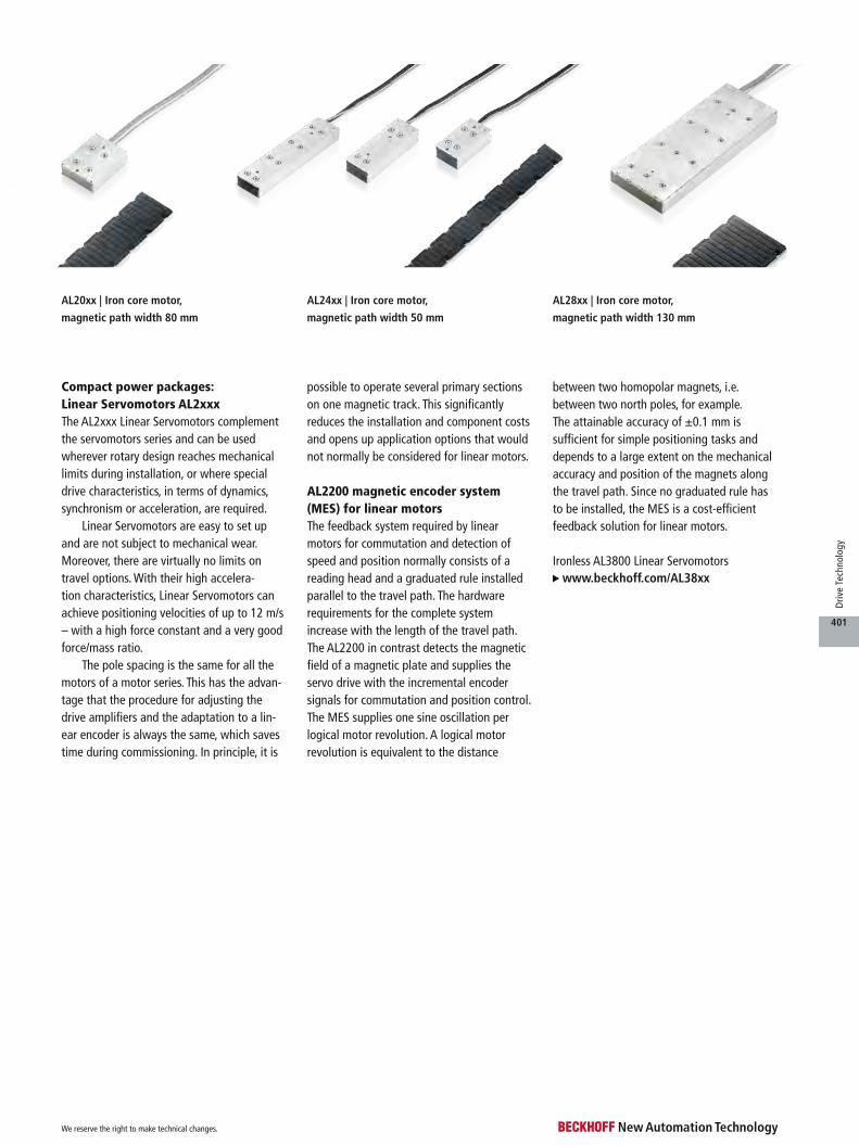
AL24xx | Iron core motor,
magnetic path width 50 mm
AL20xx | Iron core motor,
magnetic path width 80 mm
AL28xx | Iron core motor,
magnetic path width 130 mm
Compact power packages: Linear Servomotors AL2xxxThe AL2xxx Linear Servomotors complement the servomotors series and can be used wherever rotary design reaches mechanical limits during installation, or where special drive characteristics, in terms of dynamics, synchronism or acceleration, are required.
Linear Servomotors are easy to set up and are not subject to mechanical wear. Moreover, there are virtually no limits on travel options. With their high accelera-tion characteristics, Linear Servomotors can achieve positioning velocities of up to 12 m/s – with a high force constant and a very good force/mass ratio.
The pole spacing is the same for all the motors of a motor series. This has the advan-tage that the procedure for adjusting the drive amplifiers and the adaptation to a lin-ear encoder is always the same, which saves time during commissioning. In principle, it is
possible to operate several primary sections on one magnetic track. This significantly reduces the installation and component costs and opens up application options that would not normally be considered for linear motors.
AL2200 magnetic encoder system (MES) for linear motorsThe feedback system required by linear motors for commutation and detection of speed and position normally consists of a reading head and a graduated rule installed parallel to the travel path. The hardware requirements for the complete system increase with the length of the travel path. The AL2200 in contrast detects the magnetic field of a magnetic plate and supplies the servo drive with the incremental encoder signals for commutation and position control. The MES supplies one sine oscillation per logical motor revolution. A logical motor revolution is equivalent to the distance
between two homopolar magnets, i.e. between two north poles, for example. The attainable accuracy of ±0.1 mm is sufficient for simple positioning tasks and depends to a large extent on the mechanical accuracy and position of the magnets along the travel path. Since no graduated rule has to be installed, the MES is a cost-efficient feedback solution for linear motors.
Ironless AL3800 Linear Servomotors www.beckhoff.com/AL38xx
We reserve the right to make technical changes.
401
Driv
e Te
chno
logy

AL24xx AL28xx
AL20xx
AL2xxx | Linear Servomotors
AL2xxx
The 3-phase Synchronous Linear Servomotors of the AL2xxx series consist of a primary section and a secondary section. The primary section contains a grooved, lam-inated core with inlaid copper windings. It is generally used as the moving part. The second-ary section contains the steel plate with attached permanent magnets.
The motors of the individual series have the same width (including magnetic plate), i.e. all motors can be operated on the same magnetic plates, in any combination. The magnetic plates are fully sealed and therefore have an almost per-fectly level and robust surface.
The primary sections have an IP 64 protection rating and are therefore suitable for appli-cation in harsh environments. They are equipped with a 0.5 m cable strand and optionally with pre-assembled connectors, so that they can be coupled with the servo drives either via the connector box or via plug con-nectors. This greatly reduces the difficulty of implementing the
cabling, and makes a significant contribution to avoiding errors.
In conjunction with the AX5000 Servo Drives the linear motors of the AL2xxx series are very suitable for dynamic movements, which require high acceleration values over short distances.
Features– accelerations up to 30 g– no mechanical wear– complete absence of
backlash, giving stiff control response
– extremely precise position-ing, high repeatability
– even, immediate force, little cogging
– very low thermal resistance, allowing high capacity utilisation
– protection from thermal overload through integrated temperature sensors
– Operation with the AX5000 simplified through default values.
– connection to the AX5000 through pre-assembled cables
AL20xx– velocity:
2.5 m/s to 7 m/s– peak forces:
225 N to 1800 N
AL24xx– velocity:
4.5 m/s to 10 m/s– peak forces:
120 N to 720 N
AL28xx– velocity:
2.5 m/s or 6 m/s– peak forces:
1800 N to 6750 N– operation optionally with
or without water cooling
AL2200 scaleless feedback system (MES) for Linear ServomotorsAn MES system is available as an optional accessory for monitoring the magnetic field of the permanent magnets on the magnetic plate. With the aid of an integrated electronic unit, it provides incremental encoder signals for the Servo Drives of the AX5000 series for
commutation, velocity and position control. The MES provides a sine wave per 24 mm pole pitch and a precision of 1/10 mm.
AL225x connector box The AL225x connector boxes facilitate wiring between linear motor and servo drive. On one side, the motor, feedback and thermal protection cables are connected. The standard motor and encoder cables are con-nected on the other side of the boxes.
Options, pre-assembled cables and accessories see page 406
We reserve the right to make technical changes.
402
Driv
e Te
chno
logy

Technical data AL2003 AL2006 AL2009 AL2012 AL2015 AL2018 AL2024
Winding type S N | S N | S N | S N | S N | S N | S
Max. speed 7 m/s 3.5 m/s (N),
7 m/s (S)
2.5 m/s (N),
7 m/s (S)
3.5 m/s (N),
7 m/s (S)
3.5 m/s (N),
7 m/s (S)
3.5 m/s (N),
7 m/s (S)
3.5 m/s (N),
7 m/s (S)
Motor configuration 3-phase synchronous Linear Servomotors (400…480 V AC)
Peak force (FP) 225 N 450 N 675 N 900 N 1125 N 1350 N 1800 N
Peak current (IPa) 6.5 A 6.5 A (N),
13.0 A (S)
6.5 A (N),
19.6 A (S)
13.1 A (N),
26.2 A (S)
13.5 A (N),
32.7 A (S)
19.6 A (N),
41 A (S)
26.2 A (N),
52 A (S)
Continuous force with
air cooling (Fca)
75 N 200 N 300 N 400 N 500 N 600 N 800 N
Continuous current with
air cooling (Ica)
2.28 A 2.15 A (N),
4.3 A (S)
2.14 A (N),
6.45 A (S)
4.3 A (N),
8.6 A (S)
4.46 A (N),
10.75 A (S)
6.45 A (N),
13.38 A (S)
8.6 A (N),
17.2 A (S)
Force constant (Kf) 46 N/A 93 N/A (N),
46 N/A (S)
140 N/A (N),
46 N/A (S)
93 N/A (N),
46 N / A (S)
112 N/A (N),
46 N / A (S)
93 N/A (N),
44.9 N / A (S)
93 N/A (N),
46 N / A (S)
Motor constant (Km) 185 N²/W 380 N²/W 570 N²/W 760 N²/W 950 N²/ W 1140 N²/W 1520 N²/ W
Magnet pitch 24 mm
Magnetic attraction force (Fa) 500 N 950 N 1325 N 1700 N 2075 N 2450 N 3400 N
Weight of the coil (Mp) 0.9 kg 1.5 kg 2.0 kg 2.6 kg 3.2 kg 3.8 kg 5.2 kg
Air gap 0.5 mm
Temperature sensor PTC 1 kΩ and KTY83-122
Corresponding Servo Drive AX5x03 AX5x03 (N),
AX5x06 (S)
AX5x03 (N),
AX5112 (S)
AX5x06 (N),
AX5112 (S)
AX5x06 (N),
AX5112 (S)
AX5112 (N),
AX5118 (S)
AX5112 (N),
AX5118 (S)
AL2000
Dimensions b la h
AL2003 77 mm 98 mm 40 mm
AL2006 77 mm 146 mm 40 mm
AL2009 77 mm 195 mm 40 mm
AL2012 77 mm 244 mm 40 mm
AL2015 77 mm 290 mm 40 mm
AL2018 77 mm 336 mm 40 mm
AL2024 77 mm 468 mm 40 mm
Ordering information AL21xx-0000 magnet plate
AL2110-0000 magnetic assembly (lb = 192 mm, weight 3.8 kg/m), for AL20xx motors
AL2120-0000 magnetic assembly (lb = 288 mm, weight 3.8 kg/m), for AL20xx motors
Ordering information AL20xx-000x-000y coil unit
AL2003-0001-000y Linear Servomotor, 400…480 V, Fp = 225 N, Fca = 75 N
AL2006-000x-000y Linear Servomotor, 400…480 V, Fp = 450 N, Fca = 200 N
AL2009-000x-000y Linear Servomotor, 400…480 V, Fp = 675 N, Fca = 300 N
AL2012-000x-000y Linear Servomotor, 400…480 V, Fp = 900 N, Fca = 400 N
AL2015-000x-000y Linear Servomotor, 400…480 V, Fp = 1125 N, Fca = 500 N
AL2018-000x-000y Linear Servomotor, 400…480 V, Fp = 1350 N, Fca = 600 N
AL2024-000x-000y Linear Servomotor, 400…480 V, Fp = 1800 N, Fca = 800 N
b
h
la
lb
AL2000 | Linear Servomotors
Option x = 0: N type, x = 1: S type
Option y = 0: without connector plug, y = 1: with connector plugs (motor and temperature)
u www.beckhoff.com/AL20xx
We reserve the right to make technical changes.
403
Driv
e Te
chno
logy
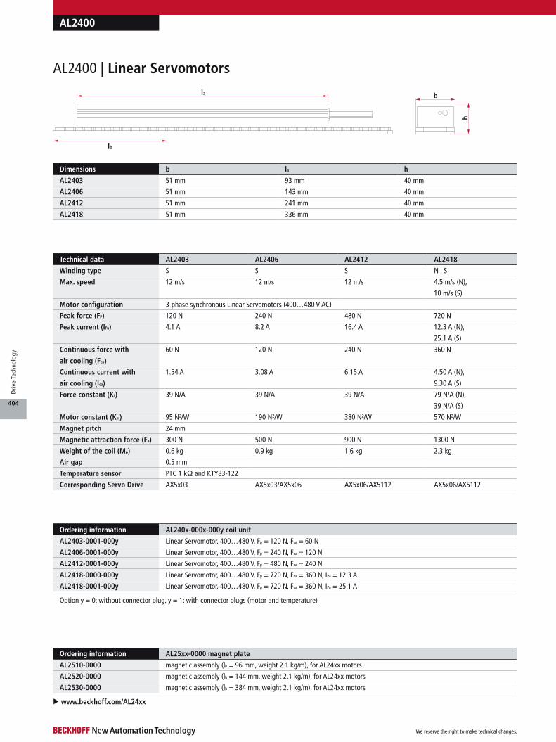
b
h
la
lb
u www.beckhoff.com/AL24xx
Ordering information AL25xx-0000 magnet plate
AL2510-0000 magnetic assembly (lb = 96 mm, weight 2.1 kg/m), for AL24xx motors
AL2520-0000 magnetic assembly (lb = 144 mm, weight 2.1 kg/m), for AL24xx motors
AL2530-0000 magnetic assembly (lb = 384 mm, weight 2.1 kg/m), for AL24xx motors
Option y = 0: without connector plug, y = 1: with connector plugs (motor and temperature)
AL2400 | Linear Servomotors
AL2400
Dimensions b la h
AL2403 51 mm 93 mm 40 mm
AL2406 51 mm 143 mm 40 mm
AL2412 51 mm 241 mm 40 mm
AL2418 51 mm 336 mm 40 mm
Ordering information AL240x-000x-000y coil unit
AL2403-0001-000y Linear Servomotor, 400…480 V, Fp = 120 N, Fca = 60 N
AL2406-0001-000y Linear Servomotor, 400…480 V, Fp = 240 N, Fca = 120 N
AL2412-0001-000y Linear Servomotor, 400…480 V, Fp = 480 N, Fca = 240 N
AL2418-0000-000y Linear Servomotor, 400…480 V, Fp = 720 N, Fca = 360 N, IPa = 12.3 A
AL2418-0001-000y Linear Servomotor, 400…480 V, Fp = 720 N, Fca = 360 N, IPa = 25.1 A
Technical data AL2403 AL2406 AL2412 AL2418
Winding type S S S N | S
Max. speed 12 m/s 12 m/s 12 m/s 4.5 m/s (N),
10 m/s (S)
Motor configuration 3-phase synchronous Linear Servomotors (400…480 V AC)
Peak force (FP) 120 N 240 N 480 N 720 N
Peak current (IPa) 4.1 A 8.2 A 16.4 A 12.3 A (N),
25.1 A (S)
Continuous force with
air cooling (Fca)
60 N 120 N 240 N 360 N
Continuous current with
air cooling (Ica)
1.54 A 3.08 A 6.15 A 4.50 A (N),
9.30 A (S)
Force constant (Kf) 39 N/A 39 N/A 39 N/A 79 N/A (N),
39 N/A (S)
Motor constant (Km) 95 N²/W 190 N²/W 380 N²/W 570 N²/W
Magnet pitch 24 mm
Magnetic attraction force (Fa) 300 N 500 N 900 N 1300 N
Weight of the coil (Mp) 0.6 kg 0.9 kg 1.6 kg 2.3 kg
Air gap 0.5 mm
Temperature sensor PTC 1 kΩ and KTY83-122
Corresponding Servo Drive AX5x03 AX5x03/AX5x06 AX5x06/AX5112 AX5x06/AX5112
We reserve the right to make technical changes.
404
Driv
e Te
chno
logy
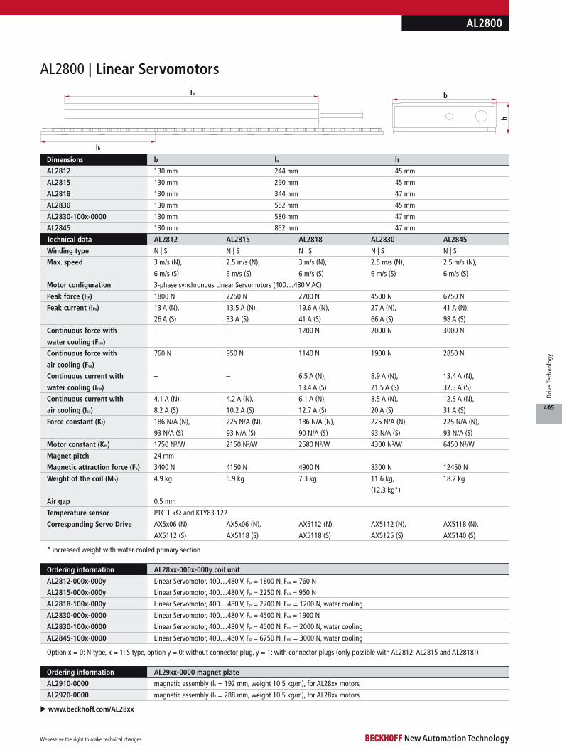
AL2800
Ordering information AL29xx-0000 magnet plate
AL2910-0000 magnetic assembly (lb = 192 mm, weight 10.5 kg/m), for AL28xx motors
AL2920-0000 magnetic assembly (lb = 288 mm, weight 10.5 kg/m), for AL28xx motors
Option x = 0: N type, x = 1: S type, option y = 0: without connector plug, y = 1: with connector plugs (only possible with AL2812, AL2815 and AL2818!)
b
h
la
lb
AL2800 | Linear Servomotors
u www.beckhoff.com/AL28xx
Dimensions b la h
AL2812 130 mm 244 mm 45 mm
AL2815 130 mm 290 mm 45 mm
AL2818 130 mm 344 mm 47 mm
AL2830 130 mm 562 mm 45 mm
AL2830-100x-0000 130 mm 580 mm 47 mm
AL2845 130 mm 852 mm 47 mm
Ordering information AL28xx-000x-000y coil unit
AL2812-000x-000y Linear Servomotor, 400…480 V, Fp = 1800 N, Fca = 760 N
AL2815-000x-000y Linear Servomotor, 400…480 V, Fp = 2250 N, Fca = 950 N
AL2818-100x-000y Linear Servomotor, 400…480 V, Fp = 2700 N, Fcw = 1200 N, water cooling
AL2830-000x-0000 Linear Servomotor, 400…480 V, Fp = 4500 N, Fca = 1900 N
AL2830-100x-0000 Linear Servomotor, 400…480 V, Fp = 4500 N, Fcw = 2000 N, water cooling
AL2845-100x-0000 Linear Servomotor, 400…480 V, Fp = 6750 N, Fcw = 3000 N, water cooling
* increased weight with water-cooled primary section
Technical data AL2812 AL2815 AL2818 AL2830 AL2845
Winding type N | S N | S N | S N | S N | S
Max. speed 3 m/s (N),
6 m/s (S)
2.5 m/s (N),
6 m/s (S)
3 m/s (N),
6 m/s (S)
2.5 m/s (N),
6 m/s (S)
2.5 m/s (N),
6 m/s (S)
Motor configuration 3-phase synchronous Linear Servomotors (400…480 V AC)
Peak force (FP) 1800 N 2250 N 2700 N 4500 N 6750 N
Peak current (IPa) 13 A (N),
26 A (S)
13.5 A (N),
33 A (S)
19.6 A (N),
41 A (S)
27 A (N),
66 A (S)
41 A (N),
98 A (S)
Continuous force with
water cooling (Fcw)
– – 1200 N 2000 N 3000 N
Continuous force with
air cooling (Fca)
760 N 950 N 1140 N 1900 N 2850 N
Continuous current with
water cooling (Icw)
– – 6.5 A (N),
13.4 A (S)
8.9 A (N),
21.5 A (S)
13.4 A (N),
32.3 A (S)
Continuous current with
air cooling (Ica)
4.1 A (N),
8.2 A (S)
4.2 A (N),
10.2 A (S)
6.1 A (N),
12.7 A (S)
8.5 A (N),
20 A (S)
12.5 A (N),
31 A (S)
Force constant (Kf) 186 N/A (N),
93 N/A (S)
225 N/A (N),
93 N/A (S)
186 N/A (N),
90 N/A (S)
225 N/A (N),
93 N/A (S)
225 N/A (N),
93 N/A (S)
Motor constant (Km) 1750 N²/W 2150 N²/W 2580 N²/W 4300 N²/W 6450 N²/W
Magnet pitch 24 mm
Magnetic attraction force (Fa) 3400 N 4150 N 4900 N 8300 N 12450 N
Weight of the coil (Mp) 4.9 kg 5.9 kg 7.3 kg 11.6 kg,
(12.3 kg*)
18.2 kg
Air gap 0.5 mm
Temperature sensor PTC 1 kΩ and KTY83-122
Corresponding Servo Drive AX5x06 (N),
AX5112 (S)
AX5x06 (N),
AX5118 (S)
AX5112 (N),
AX5118 (S)
AX5112 (N),
AX5125 (S)
AX5118 (N),
AX5140 (S)
We reserve the right to make technical changes.
405
Driv
e Te
chno
logy
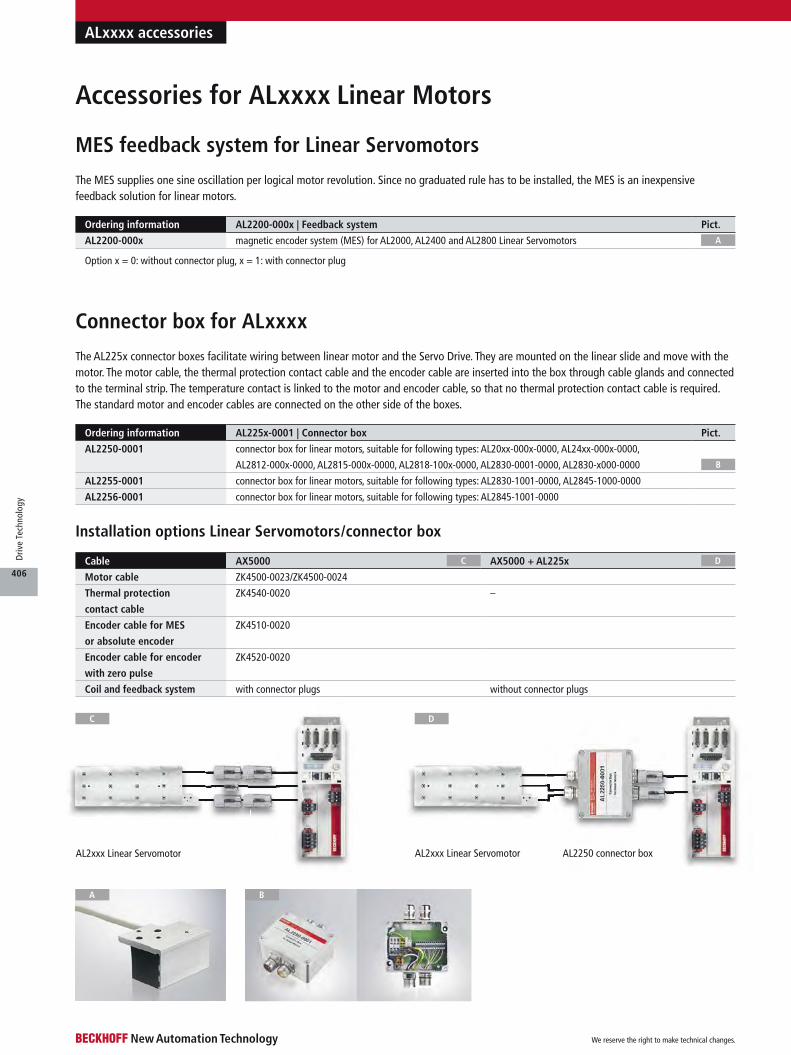
Cable AX5000 AX5000 + AL225x
Motor cable ZK4500-0023/ZK4500-0024
Thermal protection
contact cable
ZK4540-0020 –
Encoder cable for MES
or absolute encoder
ZK4510-0020
Encoder cable for encoder
with zero pulse
ZK4520-0020
Coil and feedback system with connector plugs without connector plugs
Ordering information AL2200-000x | Feedback system Pict.
AL2200-000x magnetic encoder system (MES) for AL2000, AL2400 and AL2800 Linear Servomotors
AL2xxx Linear Servomotor AL2250 connector boxAL2xxx Linear Servomotor
DC
C D
ALxxxx accessories
A
A B
The AL225x connector boxes facilitate wiring between linear motor and the Servo Drive. They are mounted on the linear slide and move with the motor. The motor cable, the thermal protection contact cable and the encoder cable are inserted into the box through cable glands and connected to the terminal strip. The temperature contact is linked to the motor and encoder cable, so that no thermal protection contact cable is required. The standard motor and encoder cables are connected on the other side of the boxes.
Installation options Linear Servomotors/connector box
Connector box for ALxxxx
Accessories for ALxxxx Linear Motors
Option x = 0: without connector plug, x = 1: with connector plug
MES feedback system for Linear Servomotors
A
The MES supplies one sine oscillation per logical motor revolution. Since no graduated rule has to be installed, the MES is an inexpensive feedback solution for linear motors.
Ordering information AL225x-0001 | Connector box Pict.
AL2250-0001 connector box for linear motors, suitable for following types: AL20xx-000x-0000, AL24xx-000x-0000,
AL2812-000x-0000, AL2815-000x-0000, AL2818-100x-0000, AL2830-0001-0000, AL2830-x000-0000
AL2255-0001 connector box for linear motors, suitable for following types: AL2830-1001-0000, AL2845-1000-0000
AL2256-0001 connector box for linear motors, suitable for following types: AL2845-1001-0000
B
We reserve the right to make technical changes.
406
Driv
e Te
chno
logy
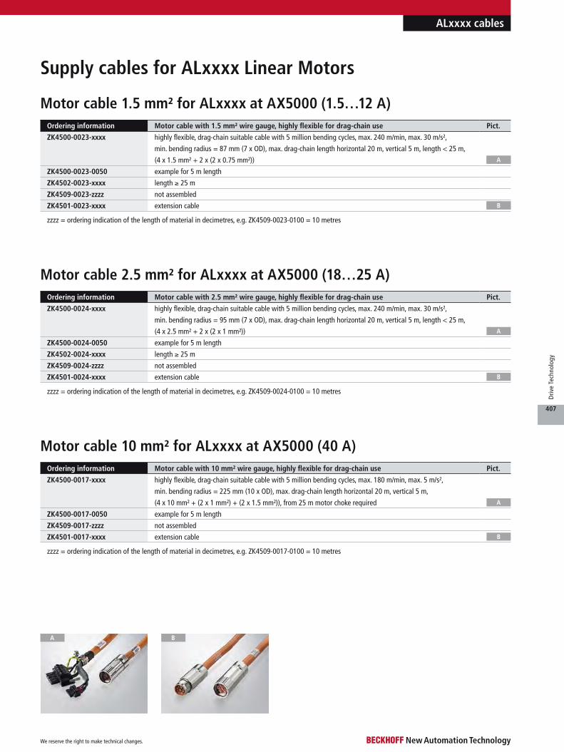
A B
ALxxxx cables
Motor cable 10 mm² for ALxxxx at AX5000 (40 A)Ordering information Motor cable with 10 mm² wire gauge, highly flexible for drag-chain use Pict.
ZK4500-0017-xxxx highly flexible, drag-chain suitable cable with 5 million bending cycles, max. 180 m/min, max. 5 m/s²,
min. bending radius = 225 mm (10 x OD), max. drag-chain length horizontal 20 m, vertical 5 m,
(4 x 10 mm² + (2 x 1 mm²) + (2 x 1.5 mm²)), from 25 m motor choke required
ZK4500-0017-0050 example for 5 m length
ZK4509-0017-zzzz not assembled
ZK4501-0017-xxxx extension cable
zzzz = ordering indication of the length of material in decimetres, e.g. ZK4509-0017-0100 = 10 metres
Supply cables for ALxxxx Linear Motors
A
B
Motor cable 1.5 mm² for ALxxxx at AX5000 (1.5…12 A)
Motor cable 2.5 mm² for ALxxxx at AX5000 (18…25 A)
E
F
Ordering information Motor cable with 1.5 mm² wire gauge, highly flexible for drag-chain use Pict.
ZK4500-0023-xxxx highly flexible, drag-chain suitable cable with 5 million bending cycles, max. 240 m/min, max. 30 m/s²,
min. bending radius = 87 mm (7 x OD), max. drag-chain length horizontal 20 m, vertical 5 m, length < 25 m,
(4 x 1.5 mm² + 2 x (2 x 0.75 mm²))
ZK4500-0023-0050 example for 5 m length
ZK4502-0023-xxxx length ≥ 25 m
ZK4509-0023-zzzz not assembled
ZK4501-0023-xxxx extension cable
A
B
zzzz = ordering indication of the length of material in decimetres, e.g. ZK4509-0023-0100 = 10 metres
Ordering information Motor cable with 2.5 mm² wire gauge, highly flexible for drag-chain use Pict.
ZK4500-0024-xxxx highly flexible, drag-chain suitable cable with 5 million bending cycles, max. 240 m/min, max. 30 m/s²,
min. bending radius = 95 mm (7 x OD), max. drag-chain length horizontal 20 m, vertical 5 m, length < 25 m,
(4 x 2.5 mm² + 2 x (2 x 1 mm²))
ZK4500-0024-0050 example for 5 m length
ZK4502-0024-xxxx length ≥ 25 m
ZK4509-0024-zzzz not assembled
ZK4501-0024-xxxx extension cable
A
B
zzzz = ordering indication of the length of material in decimetres, e.g. ZK4509-0024-0100 = 10 metres
We reserve the right to make technical changes.
407
Driv
e Te
chno
logy

ALxxxx cables
E
Ordering information Encoder cable with 0.14 mm² wire gauge, highly flexible for drag-chain use
ZK4520-0020-xxxx highly flexible, drag-chain suitable cable with 5 million bending cycles, max. 240 m/min, max. 30 m/s²,
min. bending radius = 53 mm (7 x OD), max. drag-chain length horizontal = 20 m, vertical = 5 m,
(7 x 2 x 0.14 mm² + 2 x 0.5 mm²)
Ordering information Thermal protection cable with 0.14 mm² wire gauge, highly flexible for drag-chain use Pict.
ZK4540-0020-xxxx highly flexible, drag-chain suitable cable with 5 million bending cycles, max. 240 m/min, max. 30 m/s²,
min. bending radius = 38 mm (7 x OD), max. drag-chain length horizontal = 20 m, vertical = 5 m,
(2 x 2 x 0.14 mm²)
EC D
Encoder cable (SinCos encoder with zero pulse) for ALxxxx and AL2250
at AX5000
Thermal protection cable for ALxxxx at AX5000
Encoder cable (MES) for ALxxxx and AL2250 at AX5000Ordering information Encoder cable with 0.14 mm² wire gauge, highly flexible for drag-chain use Pict.
ZK4510-0020-xxxx highly flexible, drag-chain suitable cable with 5 million bending cycles, max. 240 m/min, max. 30 m/s²,
min. bending radius = 53 mm (7 x OD), max. drag-chain length horizontal = 20 m, vertical = 5 m,
(7 x 2 x 0.14 mm² + 2 x 0.5 mm²)
ZK4510-0020-0050 example for 5 m length
ZK4519-0020-zzzz not assembled
ZK4511-0020-xxxx extension cable, highly flexible, drag-chain suitable
C
D
zzzz = ordering indication of the length of material in decimetres, e.g. ZK4519-0020-0100 = 10 metres
Note: Required if no connector box is used.
We reserve the right to make technical changes.
408
Driv
e Te
chno
logy
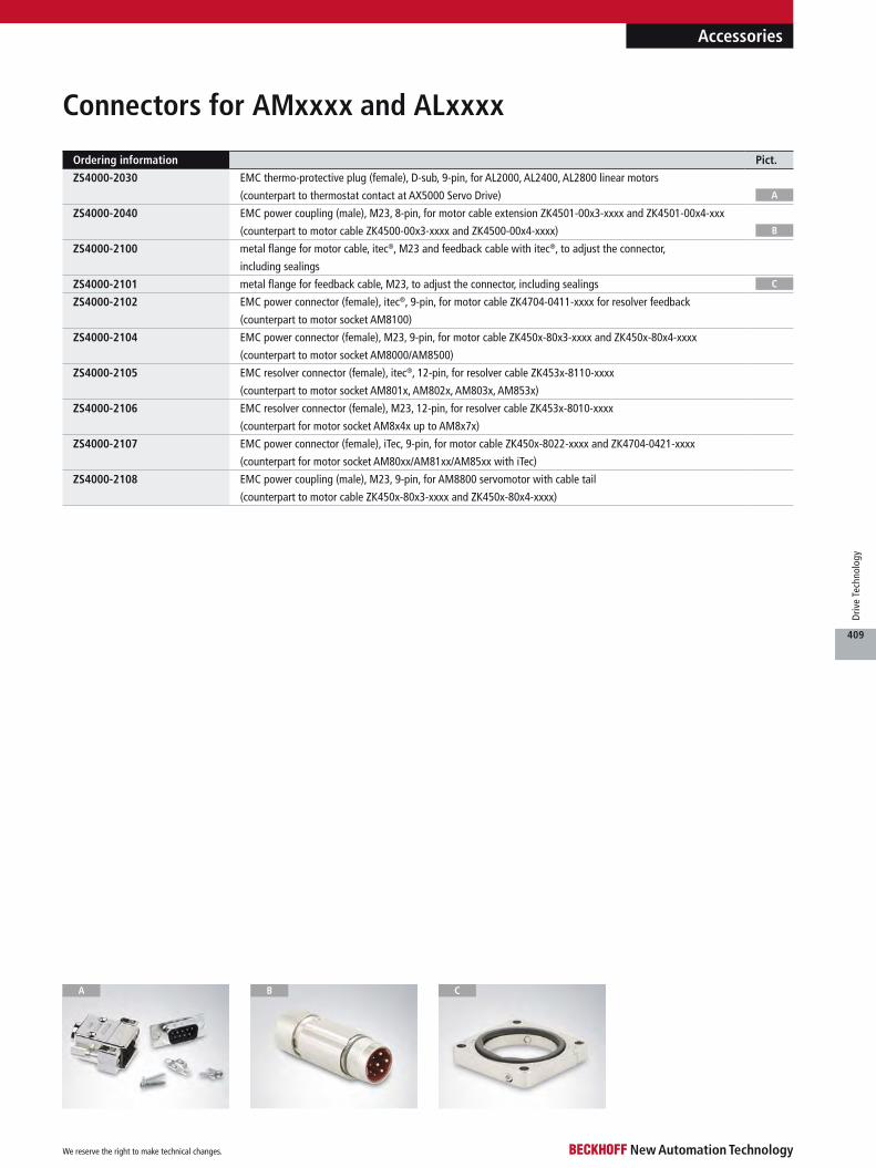
Accessories
Connectors for AMxxxx and ALxxxx
Ordering information Pict.
ZS4000-2030 EMC thermo-protective plug (female), D-sub, 9-pin, for AL2000, AL2400, AL2800 linear motors
(counterpart to thermostat contact at AX5000 Servo Drive)
ZS4000-2040 EMC power coupling (male), M23, 8-pin, for motor cable extension ZK4501-00x3-xxxx and ZK4501-00x4-xxx
(counterpart to motor cable ZK4500-00x3-xxxx and ZK4500-00x4-xxxx)
ZS4000-2100 metal flange for motor cable, itec®, M23 and feedback cable with itec®, to adjust the connector,
including sealings
ZS4000-2101 metal flange for feedback cable, M23, to adjust the connector, including sealings
ZS4000-2102 EMC power connector (female), itec®, 9-pin, for motor cable ZK4704-0411-xxxx for resolver feedback
(counterpart to motor socket AM8100)
ZS4000-2104 EMC power connector (female), M23, 9-pin, for motor cable ZK450x-80x3-xxxx and ZK450x-80x4-xxxx
(counterpart to motor socket AM8000/AM8500)
ZS4000-2105 EMC resolver connector (female), itec®, 12-pin, for resolver cable ZK453x-8110-xxxx
(counterpart to motor socket AM801x, AM802x, AM803x, AM853x)
ZS4000-2106 EMC resolver connector (female), M23, 12-pin, for resolver cable ZK453x-8010-xxxx
(counterpart for motor socket AM8x4x up to AM8x7x)
ZS4000-2107 EMC power connector (female), iTec, 9-pin, for motor cable ZK450x-8022-xxxx and ZK4704-0421-xxxx
(counterpart for motor socket AM80xx/AM81xx/AM85xx with iTec)
ZS4000-2108 EMC power coupling (male), M23, 9-pin, for AM8800 servomotor with cable tail
(counterpart to motor cable ZK450x-80x3-xxxx and ZK450x-80x4-xxxx)
A
C
B
CA B
We reserve the right to make technical changes.
409
Driv
e Te
chno
logy
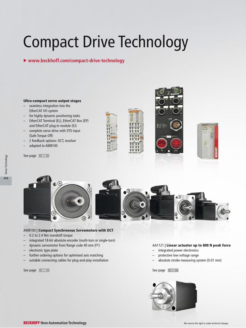
See page See page414 412
See page 314
Ultra-compact servo output stages– seamless integration into the
EtherCAT I/O system– for highly dynamic positioning tasks– EtherCAT Terminal (EL), EtherCAT Box (EP)
and EtherCAT plug-in module (EJ)– complete servo drive with STO input
(Safe Torque Off)– 2 feedback options: OCT, resolver– adapted to AM8100
AM8100 | Compact Synchronous Servomotors with OCT– 0.2 to 2.4 Nm standstill torque– integrated 18-bit absolute encoder (multi-turn or single-turn)– dynamic servomotor from flange code 40 mm (F1)– electronic type plate– further ordering options for optimised axis matching– suitable connecting cables for plug-and-play installation
AA1121 | Linear actuator up to 800 N peak force– integrated power electronics– protective low voltage range– absolute stroke measuring system (0.01 mm)
Compact Drive Technology u www.beckhoff.com/compact-drive-technology
We reserve the right to make technical changes.
410
Driv
e Te
chno
logy

AG2250 | Planetary gear units for servo and stepper motors– straight or angled design– low torsional backlash– suitable for AM8100, AS2000, AS1000
See page 418
AS1000 | Stepper motors up to 5 Nm– stepper motor with 1.8°/200 full steps– flanges: NEMA17, NEMA23, NEMA34– 0.4 to 5.0 Nm standstill torque– ready for connection, with cable outlet– optionally with encoder
See page 424
Ultra-compact stepper motor output stages– seamless integration into the I/O system– EtherCAT Terminal (EL), Bus Terminal (KL),
EtherCAT/EtherCAT P Box (EP/EPP) and EtherCAT plug-in module (EJ)
– 1 to 5 A output current– vector control for highly dynamic positioning
tasks (EL7037/EL7047/EJ7047)– assembled connecting cables
See page
AS2000 | Stepper motors in industrial design up to 8 Nm– stepper motor with 1.8°/200 full steps– flanges: NEMA23, NEMA34– 0.8 to 8.0 Nm standstill torque– industrial design and high protection class (IP 54)– optionally with torsionally rigid integrated encoder
(1024 inc/rev) for vector control
See page 420
314
We reserve the right to make technical changes.
411
Driv
e Te
chno
logy

Technical data AA1121
Motor type axis actuator
Flange code A2 (49 mm)
Rated supply voltage 24…48 V DC
Magnet material neodymium-iron-boron
Design form flange-mounted according to IM B5, IM V1, IM V3
Protection class IP 54
Connection method M12, screw type
Protocol EtherCAT
Bus interface 2 x M8 socket, shielded, screw type
Feedback system absolute encoder
Resolution 0.01 mm
The linear actuator sets new standards for the electronic con-trol of valves and linear adjust-ing units. With a lifting height of 10 mm and a peak force of 800 N, new standards are achieved with regard to the power density of linear actua-tors. The complete adjusting axis is defined with a size of only 49 x 49 x 92 mm (flange square x overall length).
The linear actuator is equipped with integrated power electronics that is controlled simply and extremely fast via EtherCAT. For easy commission-
ing the well-known Drive Man-ager can be used. A continuous force of 150 N can be generated with the actuator. Accelerations of 7 m/s² and linear speeds of 100 mm/s allow exceptionally short control cycles. Mounting via a B5 flange is possible with-out special tools in the tightest of spaces. The shaft is provided as standard with an M8x1 exter-nal thread, on which commer-cially available adaptors such as ball heads or tensioning hooks common in pneumatic/hydraulic applications can be mounted. For connection in the protective
low voltage range < 48 V DC a robust M12 plug can be used. The fieldbus connections for EtherCAT IN/OUT are realised with M8 plugs.
An absolute stroke measur-ing system is integrated, allow-ing an accuracy of 0.01 mm to be achieved so that previously necessary limit switches are not required. In comparison with conventional pneumatics, the linear actuator achieves a much higher positioning accuracy, resulting in higher process safety. This holds above all for distrib-uted systems. Depending on the
application, the use of an elec-tronic actuator can save up to 75 % energy in comparison with pneumatic actuators, so that the linear actuator enables a rapid return on investment. Beckhoff supplies the necessary preassem-bled cables and the software to go with the actuators.
AA1121 | Linear actuator with integrated power electronics
AA1121
We reserve the right to make technical changes.
412
Driv
e Te
chno
logy

Data for 24…50 V DC AA1121
Continuous stall force 200 N
Rated force 150 N
Peak force (FP) 800 N
Standstill current Irms = 2.5 A
Peak current Irms = 10.0 A
Max. movement 10 mm
Max. acceleration 7 m/s²
Weight 840 g
Dimensions a b d xE xU l r k
AA1121 ø28 M8 16 mm 71.5 mm 81.5 mm 19.5 mm 49 mm 92 mm
k
b
l
l
l
l
UP/US
X2 OUT
X1 IN
xU
xE
d a
r
AA1121
AA1121 | Flange code A2, motor length 1
For availability status see Beckhoff website at: www.beckhoff.com/AA1121
u www.beckhoff.com/AA1121
Supply cables for linear actuator
Ordering information Cable specification
ZK1090-3131-0xxx M8, plug, straight, male, 4-pin, A-coded – M8, plug, straight, male, 4-pin, A-coded
ZK1090-3191-0xxx M8, plug, straight, male, 4-pin, A-coded – RJ45, plug, straight, male, 8-pin
ZK2000-6100-0xxx M12, plug, straight, male, 4-pin, A-coded – open end
We reserve the right to make technical changes.
413
Driv
e Te
chno
logy
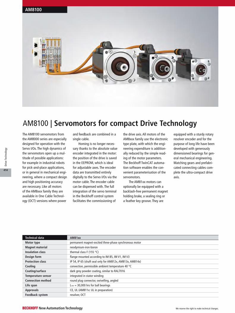
AM8100
AM8100 | Servomotors for compact Drive TechnologyThe AM8100 servomotors from the AM8000 series are especially designed for operation with the Servo I/Os. The high dynamics of the servomotors open up a mul-titude of possible applications: for example in industrial robots for pick-and-place applications, or in general in mechanical engi-neering, where a compact design and high positioning accuracy are necessary. Like all motors of the AM8xxx family they are available in One Cable Technol-ogy (OCT) versions where power
and feedback are combined in a single cable.
Homing is no longer neces-sary thanks to the absolute value encoder integrated in the motor: the position of the drive is saved in the EEPROM, which is ideal for adjustable axes. The encoder data are transmitted entirely digitally to the Servo I/Os via the motor cable. The encoder cable can be dispensed with. The full integration of the servo terminal in the Beckhoff control system facilitates the commissioning of
the drive axis. All motors of the AM8xxx family use the electronic type plate, with which the engi-neering expenditure is addition-ally reduced by the simple read-ing of the motor parameters. The Beckhoff TwinCAT automa-tion software enables the con-venient parameterisation of the servomotors.
The AM81xx motors can optionally be equipped with a backlash-free permanent magnet holding brake, a sealing ring or a feather key groove. They are
equipped with a sturdy rotary resolver encoder and for the purpose of long life have been developed with generously dimensioned bearings for gen-eral mechanical engineering. Matching gears and prefabri- cated connecting cables com-plete the ultra-compact drive axis.
Technical data AM81xx
Motor type permanent magnet-excited three-phase synchronous motor
Magnet material neodymium-iron-boron
Insulation class thermal class F (155 °C)
Design form flange-mounted according to IM B5, IM V1, IM V3
Protection class IP 54, IP 65 (shaft seal only for AM812x, AM813x, AM814x)
Cooling convection, permissible ambient temperature 40 °C
Coating/surface dark grey powder coating, similar to RAL7016
Temperature sensor integrated in stator winding
Connection method round plug connector, swivelling, angled
Life span L10h = 30,000 hrs for ball bearings
Approvals CE, UL (AM811x: UL in preparation)
Feedback system resolver, OCT
We reserve the right to make technical changes.
414
Driv
e Te
chno
logy
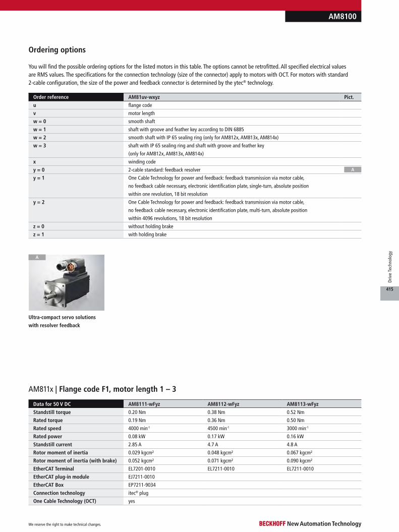
AM3000
AM811x | Flange code F1, motor length 1 – 3
Order reference AM81uv-wxyz Pict.
u flange code
v motor length
w = 0 smooth shaft
w = 1 shaft with groove and feather key according to DIN 6885
w = 2 smooth shaft with IP 65 sealing ring (only for AM812x, AM813x, AM814x)
w = 3 shaft with IP 65 sealing ring and shaft with groove and feather key
(only for AM812x, AM813x, AM814x)
x winding code
y = 0 2-cable standard: feedback resolver
y = 1 One Cable Technology for power and feedback: feedback transmission via motor cable,
no feedback cable necessary, electronic identification plate, single-turn, absolute position
within one revolution, 18 bit resolution
y = 2 One Cable Technology for power and feedback: feedback transmission via motor cable,
no feedback cable necessary, electronic identification plate, multi-turn, absolute position
within 4096 revolutions, 18 bit resolution
z = 0 without holding brake
z = 1 with holding brake
Ordering options
You will find the possible ordering options for the listed motors in this table. The options cannot be retrofitted. All specified electrical values are RMS values. The specifications for the connection technology (size of the connector) apply to motors with OCT. For motors with standard 2-cable configuration, the size of the power and feedback connector is determined by the ytec® technology.
Data for 50 V DC AM8111-wFyz AM8112-wFyz AM8113-wFyz
Standstill torque 0.20 Nm 0.38 Nm 0.52 Nm
Rated torque 0.19 Nm 0.36 Nm 0.50 Nm
Rated speed 4000 min-1 4500 min-1 3000 min-1
Rated power 0.08 kW 0.17 kW 0.16 kW
Standstill current 2.85 A 4.7 A 4.8 A
Rotor moment of inertia 0.029 kgcm² 0.048 kgcm² 0.067 kgcm²
Rotor moment of inertia (with brake) 0.052 kgcm² 0.071 kgcm² 0.090 kgcm²
EtherCAT Terminal EL7201-0010 EL7211-0010 EL7211-0010
EtherCAT plug-in module EJ7211-0010
EtherCAT Box EP7211-9034
Connection technology itec® plug
One Cable Technology (OCT) yes
AM8100
Ultra-compact servo solutions
with resolver feedback
A
A
We reserve the right to make technical changes.
415
Driv
e Te
chno
logy
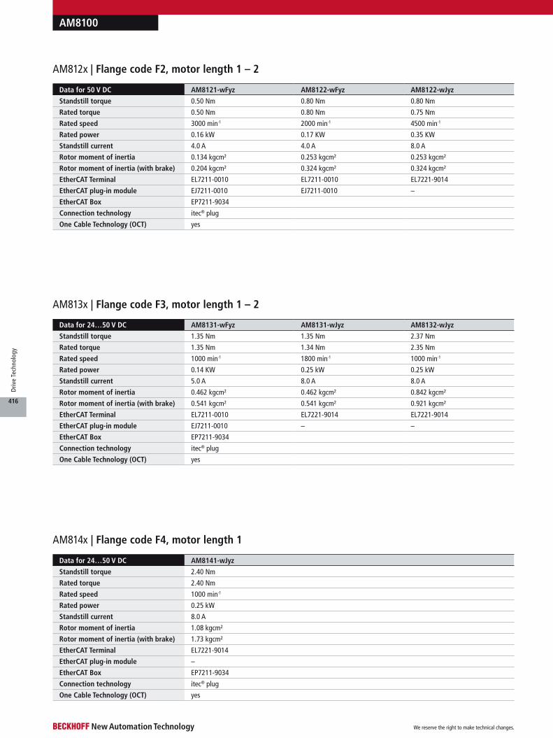
AM8100
AM813x | Flange code F3, motor length 1 – 2
AM814x | Flange code F4, motor length 1
Data for 24…50 V DC AM8131-wFyz AM8131-wJyz AM8132-wJyz
Standstill torque 1.35 Nm 1.35 Nm 2.37 Nm
Rated torque 1.35 Nm 1.34 Nm 2.35 Nm
Rated speed 1000 min-1 1800 min-1 1000 min-1
Rated power 0.14 KW 0.25 kW 0.25 kW
Standstill current 5.0 A 8.0 A 8.0 A
Rotor moment of inertia 0.462 kgcm² 0.462 kgcm² 0.842 kgcm²
Rotor moment of inertia (with brake) 0.541 kgcm² 0.541 kgcm² 0.921 kgcm²
EtherCAT Terminal EL7211-0010 EL7221-9014 EL7221-9014
EtherCAT plug-in module EJ7211-0010 – –
EtherCAT Box EP7211-9034
Connection technology itec® plug
One Cable Technology (OCT) yes
Data for 24…50 V DC AM8141-wJyz
Standstill torque 2.40 Nm
Rated torque 2.40 Nm
Rated speed 1000 min-1
Rated power 0.25 kW
Standstill current 8.0 A
Rotor moment of inertia 1.08 kgcm²
Rotor moment of inertia (with brake) 1.73 kgcm²
EtherCAT Terminal EL7221-9014
EtherCAT plug-in module –
EtherCAT Box EP7211-9034
Connection technology itec® plug
One Cable Technology (OCT) yes
AM812x | Flange code F2, motor length 1 – 2
Data for 50 V DC AM8121-wFyz AM8122-wFyz AM8122-wJyz
Standstill torque 0.50 Nm 0.80 Nm 0.80 Nm
Rated torque 0.50 Nm 0.80 Nm 0.75 Nm
Rated speed 3000 min-1 2000 min-1 4500 min-1
Rated power 0.16 kW 0.17 KW 0.35 KW
Standstill current 4.0 A 4.0 A 8.0 A
Rotor moment of inertia 0.134 kgcm² 0.253 kgcm² 0.253 kgcm²
Rotor moment of inertia (with brake) 0.204 kgcm² 0.324 kgcm² 0.324 kgcm²
EtherCAT Terminal EL7211-0010 EL7211-0010 EL7221-9014
EtherCAT plug-in module EJ7211-0010 EJ7211-0010 –
EtherCAT Box EP7211-9034
Connection technology itec® plug
One Cable Technology (OCT) yes
We reserve the right to make technical changes.
416
Driv
e Te
chno
logy

AM3000AM8100
d k ±1
l a
One Cable Technology Resolver version
b
r
u www.beckhoff.com/AM81xx
Dimensions a b d l r k (without
brake)
k (with
brake)
AM8111 30 h7 8 h7 25 mm 46 mm 40 mm 97 mm 129 mm
AM8112 30 h7 8 h7 25 mm 46 mm 40 mm 117 mm 149 mm
AM8113 30 h7 8 h7 25 mm 46 mm 40 mm 137 mm 169 mm
AM8121 40 j6 9 k6 20 mm 63 mm 58 mm 111.5 mm 146 mm
AM8122 40 j6 9 k6 20 mm 63 mm 58 mm 133.5 mm 168 mm
AM8131 60 j6 14 k6 30 mm 75 mm 72 mm 129 mm 168 mm
AM8132 60 j6 14 k6 30 mm 75 mm 72 mm 154 mm 194 mm
AM8141 80 j6 19 k6 40 mm 100 mm 87 mm 132 mm 179.5 mm
(1) Available in lengths of 1 m, 3 m, 5 m, 10 m and 20 m (2xxx = length in decimetres, e.g. -2010 = 1 m)
Technical data for drag-chain use u www.beckhoff.com/compact-drive-technology
Supply cables for servomotor terminals with OCT (and STO)
Supply cables for servomotor terminals with resolver
Accessories for AM8100 servomotors
B
(1) Available in metres up to 20 m (2xxx = length in decimetres, e.g. -2010 = 1 m)
Ordering information Suitable for EL72xx-0000 Pict.
ZK4704-0411-2xxx motor cable for resolver feedback, drag-chain suitable, (4 x 0.75 mm² + (2 x 0.5 mm²)), shielded (1)
ZK4724-0410-2xxx resolver cable, drag-chain suitable, (3 x 2 x 0.25 mm²), shielded (1)
Ordering information Suitable for EL72xx-0010, EL72xx-9014 Pict.
ZK4704-0421-2xxx motor cable for OCT feedback, drag-chain suitable, (4 x 0.75 mm² + (2 x 0.34 mm²) + (2 x AWG22)), shielded (1)
ZK4704-0421-2050 example for 5 m length
ZK4701-0421-2xxx extension cable
A
A B
We reserve the right to make technical changes.
417
Driv
e Te
chno
logy
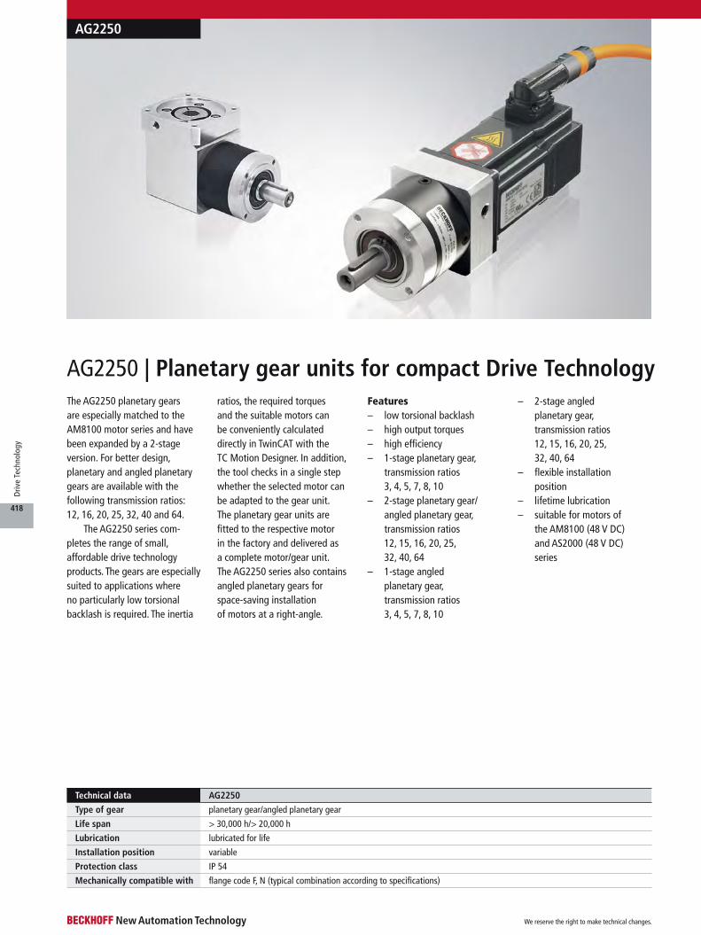
Technical data AG2250
Type of gear planetary gear/angled planetary gear
Life span > 30,000 h/> 20,000 h
Lubrication lubricated for life
Installation position variable
Protection class IP 54
Mechanically compatible with flange code F, N (typical combination according to specifications)
The AG2250 planetary gears are especially matched to the AM8100 motor series and have been expanded by a 2-stage version. For better design, planetary and angled planetary gears are available with the following transmission ratios: 12, 16, 20, 25, 32, 40 and 64.
The AG2250 series com-pletes the range of small, affordable drive technology products. The gears are especially suited to applications where no particularly low torsional backlash is required. The inertia
ratios, the required torques and the suitable motors can be conveniently calculated directly in TwinCAT with the TC Motion Designer. In addition, the tool checks in a single step whether the selected motor can be adapted to the gear unit. The planetary gear units are fitted to the respective motor in the factory and delivered as a complete motor/gear unit. The AG2250 series also contains angled planetary gears for space-saving installation of motors at a right-angle.
Features– low torsional backlash– high output torques– high efficiency– 1-stage planetary gear,
transmission ratios 3, 4, 5, 7, 8, 10
– 2-stage planetary gear/angled planetary gear, transmission ratios 12, 15, 16, 20, 25, 32, 40, 64
– 1-stage angled planetary gear, transmission ratios 3, 4, 5, 7, 8, 10
– 2-stage angled planetary gear, transmission ratios 12, 15, 16, 20, 25, 32, 40, 64
– flexible installation position
– lifetime lubrication– suitable for motors of
the AM8100 (48 V DC) and AS2000 (48 V DC) series
AG2250
AG2250 | Planetary gear units for compact Drive Technology
We reserve the right to make technical changes.
418
Driv
e Te
chno
logy

AG2250
u www.beckhoff.com/AG2250
Technical data AG2250-+PLE40-M01-i AG2250-+PLE40-M02-i AG2250-+WPLE40-M01-i AG2250-+WPLE40-M02-i
Variant planetary gear planetary gear angled planetary gear angled planetary gear
Gear ratio 3/4/5/7/8/10 12/15/16/20/25/32/40/64 3/4/5/7/8/10 12/15/16/20/25/32/40/64
Nominal output torque 5…15 Nm 7.5…20 Nm 4.5…8.5 Nm 7.5…20 Nm
Max. acceleration torque 8…24 Nm 12…32 Nm 7…13.5 Nm 12…32 Nm
Max. torsion. backlash standard/reduced ≤ 15/– arcmin ≤ 19/– arcmin ≤ 21/– arcmin ≤ 25/– arcmin
Typ. flange code F1 F1 F1 F1
AG2250 | Size 40
Technical data AG2250-+PLE60-M01-i AG2250-+PLE60-M02-i AG2250-+WPLE60-M01-i AG2250-+WPLE60-M02-i
Variant planetary gear planetary gear angled planetary gear angled planetary gear
Gear ratio 3/4/5/7/8/10 12/15/16/20/25/32/40/64 3/4/5/7/8/10 12/15/16/20/25/32/40/64
Nominal output torque 15…40 Nm 18…44 Nm 14…25 Nm 18…44 Nm
Max. acceleration torque 24…64 Nm 29…70 Nm 24…40 Nm 29…70 Nm
Max. torsion. backlash standard/reduced ≤ 10/– arcmin ≤ 12/– arcmin ≤ 16/– arcmin ≤ 18/– arcmin
Typ. flange code F2, F3, AM312x, N2 F2, F3, AM312x F2, F3, AM312x, N2 F2, F3, AM312x
AG2250 | Size 60
Technical data AG2250-+PLE80-M01-i-wXy-AS204x AG2250-+WPLE80-M01-i-wXy-AS204x
Variant planetary gear angled planetary gear
Gear ratio 3/4/5/7/8/10 3/4/5/7/8/10
Nominal output torque 38…115 Nm 38…67 Nm
Max. acceleration torque 61…184 Nm 61…107 Nm
Max. torsion. backlash standard/reduced ≤ 7/– arcmin ≤ 13/– arcmin
Typ. flange code N3 N3
AG2250 | Size 80
You will find the possible ordering options for the gear units listed in this table. Please note: The options cannot be retrofitted.
Ordering options
Order reference AG2250-+PLEaa-M0s-i-wXy-Motorsize
xPLEaa series/size (PLE40, PLE60, PLE80, WPLE40, WPLE60, WPLE80)
s = 1 1-stage with i = 3/4/5/7/8/10
s = 2 2-stage with i = 12/16/20/25/32/40/64
i gear ratio
w = 0 smooth shaft
w = 1 shaft with groove and feather key
X identifying letter for clamping hub diameter;
not available for selection, is selected automatically based on the respective motor
Motorsize Specification of the size according to flange-compatible motors.
The planetary gears are delivered as a unit with the assembled motor.
Motorsize = AM811x (F1) flange code F1: AM801x, AM811x; compatible with AM301x, AM311x
Motorsize = AM812x (F2) flange code F2: AM802x, AM812x; compatible with AM302x
Motorsize = AM312x in combination with AM312x
Motorsize = AM813x (F3) flange code F3: AM813x, AM803x, AM853x; compatible with AM303x
Motorsize = AM814x (F4) flange code F4: AM814x, AM804x, AM854x; compatible with AM304x
Motorsize = AS202x (N2) flange code N2 (NEMA23): AS202x
Motorsize = AS204x (N3) flange code N3 (NEMA34): AS204x
We reserve the right to make technical changes.
419
Driv
e Te
chno
logy
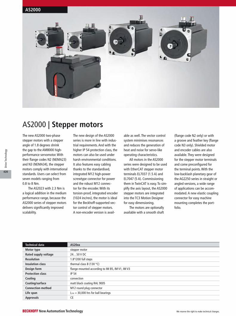
The new AS2000 two-phase stepper motors with a stepper angle of 1.8 degrees shrink the gap to the AM8000 high-performance servomotor. With their flange codes N2 (NEMA23) and N3 (NEMA34), the stepper motors comply with international standards. Users can select from seven models ranging from 0.8 to 8 Nm.
The AS2023 with 2.3 Nm is a logical addition in the medium performance range, because the AS2000 series of stepper motors delivers significantly improved scalability.
The new design of the AS2000 series is more in line with indus-trial requirements. And with the higher IP 54 protection class, the motors can also be used under harsh environmental conditions. It also features easy cabling thanks to the standardised, integrated M12 high-power screwtype connector for power and the robust M12 connec-tor for the encoder. With its torsion-proof, integrated encoder (1024 inc/rev), the motor is ideal for the Beckhoff-supported vec-tor control of stepper motors. A non-encoder version is avail-
able as well. The vector control system minimises resonances and reduces the generation of heat and noise for servo-like operating characteristics.
All motors in the AS2000 series were designed to be used with EtherCAT stepper motor terminals EL7037 (1.5 A) and EL7047 (5 A). Commissioning them in TwinCAT is easy. To sim-plify the axis layout, the AS2000 stepper motors are integrated into the TC3 Motion Designer for easy dimensioning.
The motors are optionally available with a smooth shaft
(flange code N2 only) or with a groove and feather key (flange code N3 only). Shielded motor and encoder cables are also available. They were designed for the stepper motor terminals and come preconfigured for the terminal points. With the low-backlash planetary gear of the AG2250 series in straight or angled versions, a wide range of applications can be accom-modated. A new elastic coupling connector for easy machine mounting completes the port-folio.
Technical data AS20xx
Motor type stepper motor
Rated supply voltage 24…50 V DC
Resolution 1.8°/200 full steps
Insulation class thermal class B (130 °C)
Design form flange-mounted according to IM B5, IM V1, IM V3
Protection class IP 54
Cooling convection
Coating/surface matt black coating RAL 9005
Connection method M12 round plug connector
Life span L10h = 30,000 hrs for ball bearings
Approvals CE
AS2000
AS2000 | Stepper motors
We reserve the right to make technical changes.
420
Driv
e Te
chno
logy
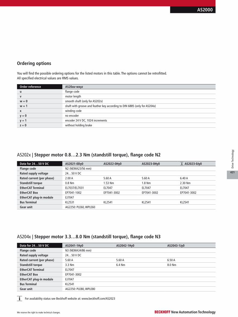
AS2000
Order reference AS20uv-wxyz
u flange code
v motor length
w = 0 smooth shaft (only for AS202x)
w = 1 shaft with groove and feather key according to DIN 6885 (only for AS204x)
x winding code
y = 0 no encoder
y = 1 encoder 24 V DC, 1024 increments
z = 0 without holding brake
Ordering options
You will find the possible ordering options for the listed motors in this table. The options cannot be retrofitted. All specified electrical values are RMS values.
Data for 24…50 V DC AS2041-1Hy0 AS2042-1Hy0 AS2043-1Jy0
Flange code N3 (NEMA34/86 mm)
Rated supply voltage 24…50 V DC
Rated current (per phase) 5.60 A 5.60 A 6.50 A
Standstill torque 3.3 Nm 6.4 Nm 8.0 Nm
EtherCAT Terminal EL7047
EtherCAT Box EP7041-3002
EtherCAT plug-in module EJ7047
Bus Terminal KL2541
Gear unit AG2250: PLE80, WPLE80
Data for 24…50 V DC AS2021-0Dy0 AS2022-0Hy0 AS2023-0Hy0 AS2023-0Jy0
Flange code N2 (NEMA23/56 mm)
Rated supply voltage 24…50 V DC
Rated current (per phase) 2.00 A 5.60 A 5.60 A 6.40 A
Standstill torque 0.8 Nm 1.53 Nm 1.8 Nm 2.30 Nm
EtherCAT Terminal EL7037/EL7031 EL7047 EL7047 EL7047
EtherCAT Box EP7041-1002 EP7041-3002 EP7041-3002 EP7041-3002
EtherCAT plug-in module EJ7047
Bus Terminal KL2531 KL2541 KL2541 KL2541
Gear unit AG2250: PLE60, WPLE60
AS204x | Stepper motor 3.3…8.0 Nm (standstill torque), flange code N3
For availability status see Beckhoff website at: www.beckhoff.com/AS2023
AS202x | Stepper motor 0.8…2.3 Nm (standstill torque), flange code N2
We reserve the right to make technical changes.
421
Driv
e Te
chno
logy
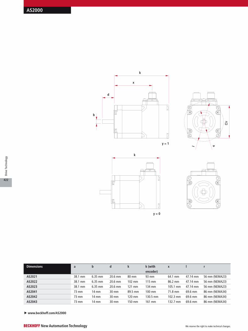
AS2000
u www.beckhoff.com/AS2000
y = 0
b
y = 1
d
k
l a
k
x
r
Dimensions a b d k k (with
encoder)
x l r
AS2021 38.1 mm 6.35 mm 20.6 mm 80 mm 93 mm 64.1 mm 47.14 mm 56 mm (NEMA23)
AS2022 38.1 mm 6.35 mm 20.6 mm 102 mm 115 mm 86.2 mm 47.14 mm 56 mm (NEMA23)
AS2023 38.1 mm 6.35 mm 20.6 mm 121 mm 134 mm 105.1 mm 47.14 mm 56 mm (NEMA23)
AS2041 73 mm 14 mm 30 mm 89.5 mm 100 mm 71.8 mm 69.6 mm 86 mm (NEMA34)
AS2042 73 mm 14 mm 30 mm 120 mm 130.5 mm 102.3 mm 69.6 mm 86 mm (NEMA34)
AS2043 73 mm 14 mm 30 mm 150 mm 161 mm 132.7 mm 69.6 mm 86 mm (NEMA34)
We reserve the right to make technical changes.
422
Driv
e Te
chno
logy

Accessories for AS2000 stepper motors
Coupling for AS2000
Pre-assembled cables for IP 20
Pre-assembled cables for IP 67
Ordering information Motor and encoder cables for IP 67 I/Os Pict.
ZK4000-6877-xxxx AS2000 motor cable, drag-chain suitable, (4 x 0.75 mm²), shielded, for EP704x/EJ704x
ZK4000-5151-xxxx AS2000 encoder cable, drag-chain suitable, (5 x 0.25 mm²), shielded, for EP704x/EJ704x
Ordering information Motor and encoder cables for IP 20 I/Os Pict.
ZK4000-7700-xxxx AS2000 motor cable, drag-chain suitable, (4 x 0.75 mm²), shielded, for EL703x/EL704x/KL253x/KL254x
ZK4000-5100-2xxx AS2000 encoder cable, drag-chain suitable, (5 x 0.25 mm²), shielded, for EL703x/EL704x/KL253x/KL254x
Ordering information AG2090-+JCbb-c/d
AX2090-+JC05-c/d jaw-type coupling for flange code N2 (AS202x), available in (drive/output) 6.35/6.00 mm, 6.35/6.35 mm, 6.35/8.00 mm
AX2090-+JC10-c/d jaw-type coupling for flange code N3 (AS204x), available in (drive/output) 14.0/14.0 mm, 14.0/16.0 mm
A CB D
D
C
B
A
AS2000
Max. cable length 10 m, available in lengths of 1 m, 3 m, 5 m and 10 m (xxx = length in decimetres, e.g. -2010 = 1 m)
Technical data for drag-chain use u www.beckhoff.com/compact-drive-technology
Max. cable length 10 m, available in lengths of 1 m, 3 m, 5 m and 10 m (xxx = length in decimetres, e.g. -2010 = 1 m)
Technical data for drag-chain use u www.beckhoff.com/compact-drive-technology
We reserve the right to make technical changes.
423
Driv
e Te
chno
logy
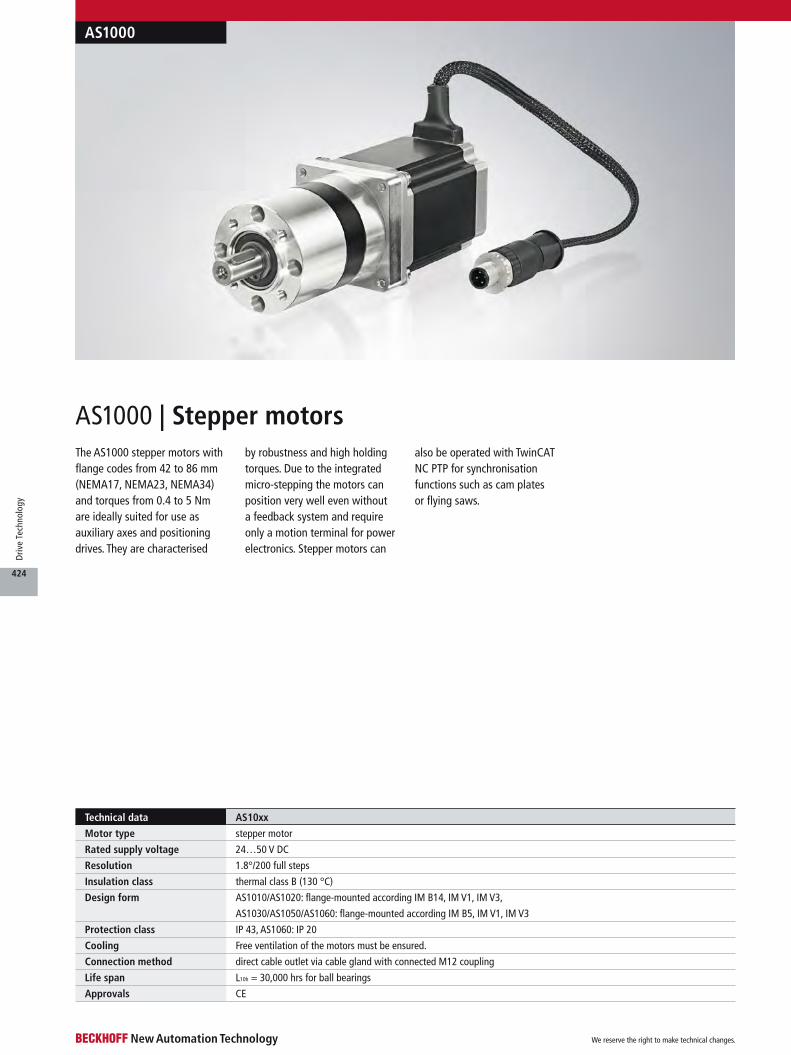
The AS1000 stepper motors with flange codes from 42 to 86 mm (NEMA17, NEMA23, NEMA34) and torques from 0.4 to 5 Nm are ideally suited for use as auxiliary axes and positioning drives. They are characterised
by robustness and high holding torques. Due to the integrated micro-stepping the motors can position very well even without a feedback system and require only a motion terminal for power electronics. Stepper motors can
also be operated with TwinCAT NC PTP for synchronisation functions such as cam plates or flying saws.
AS1000 | Stepper motors
AS1000
Technical data AS10xx
Motor type stepper motor
Rated supply voltage 24…50 V DC
Resolution 1.8°/200 full steps
Insulation class thermal class B (130 °C)
Design form AS1010/AS1020: flange-mounted according IM B14, IM V1, IM V3,
AS1030/AS1050/AS1060: flange-mounted according IM B5, IM V1, IM V3
Protection class IP 43, AS1060: IP 20
Cooling Free ventilation of the motors must be ensured.
Connection method direct cable outlet via cable gland with connected M12 coupling
Life span L10h = 30,000 hrs for ball bearings
Approvals CE
We reserve the right to make technical changes.
424
Driv
e Te
chno
logy
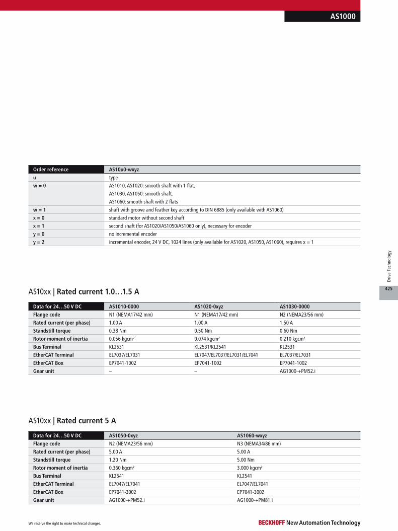
AS1000
Order reference AS10u0-wxyz
u type
w = 0 AS1010, AS1020: smooth shaft with 1 flat,
AS1030, AS1050: smooth shaft,
AS1060: smooth shaft with 2 flats
w = 1 shaft with groove and feather key according to DIN 6885 (only available with AS1060)
x = 0 standard motor without second shaft
x = 1 second shaft (for AS1020/AS1050/AS1060 only), necessary for encoder
y = 0 no incremental encoder
y = 2 incremental encoder, 24 V DC, 1024 lines (only available for AS1020, AS1050, AS1060), requires x = 1
Data for 24…50 V DC AS1010-0000 AS1020-0xyz AS1030-0000
Flange code N1 (NEMA17/42 mm) N1 (NEMA17/42 mm) N2 (NEMA23/56 mm)
Rated current (per phase) 1.00 A 1.00 A 1.50 A
Standstill torque 0.38 Nm 0.50 Nm 0.60 Nm
Rotor moment of inertia 0.056 kgcm² 0.074 kgcm² 0.210 kgcm²
Bus Terminal KL2531 KL2531/KL2541 KL2531
EtherCAT Terminal EL7037/EL7031 EL7047/EL7037/EL7031/EL7041 EL7037/EL7031
EtherCAT Box EP7041-1002 EP7041-1002 EP7041-1002
Gear unit – – AG1000-+PM52.i
Data for 24…50 V DC AS1050-0xyz AS1060-wxyz
Flange code N2 (NEMA23/56 mm) N3 (NEMA34/86 mm)
Rated current (per phase) 5.00 A 5.00 A
Standstill torque 1.20 Nm 5.00 Nm
Rotor moment of inertia 0.360 kgcm² 3.000 kgcm²
Bus Terminal KL2541 KL2541
EtherCAT Terminal EL7047/EL7041 EL7047/EL7041
EtherCAT Box EP7041-3002 EP7041-3002
Gear unit AG1000-+PM52.i AG1000-+PM81.i
AS10xx | Rated current 1.0…1.5 A
AS10xx | Rated current 5 A
We reserve the right to make technical changes.
425
Driv
e Te
chno
logy

Cables for AS1000 at Bus Terminal/EtherCAT Terminal up to 5 A
Accessories for AS1000 stepper motors
A
B
AS1000
a
b
d k m
lo r
u www.beckhoff.com/AS10xx
Dimensions a b d k l m o r
AS1010 22 mm 5 mm 24 mm 39 mm 31 mm – – 42 mm (NEMA17)
AS1020 22 mm 5 mm 24 mm 48 mm 31 mm 33 mm 24 mm 42 mm (NEMA17)
AS1030 38.1 mm 6.35 mm 20.6 mm 54 mm 47.14 mm – – 56 mm (NEMA23)
AS1050 38.1 mm 6.35 mm 20.6 mm 75.8 mm 47.14 mm 33 mm 24 mm 56 mm (NEMA23)
AS1060 73 mm 14 mm 30 mm 96.5 mm 69.6 mm 33 mm 24 mm 86 mm (NEMA34)
Available in lengths of 1 m, 3 m, 5 m and 10 m (2xxx = length in decimetres, e.g. -2010 = 1 m)
Technical data for drag-chain use u www.beckhoff.com/compact-drive-technology
A B
Ordering information Cables for stepper terminals EL7031, EL7037, EL7041, EL7047 and KL2531, KL2541 Pict.
ZK4000-5100-2xxx encoder cable for ASxxxx, IP 67, PUR, (5 x 0.25 mm²), shielded, flex, M12, plug, straight,
male, 5-pin, A-coded – open end
ZK4000-6700-2xxx motor cable for AS1000, assembled at both ends, (4 x 0.5 mm²), shielded, 4 million bending cycles,
bending radius = 55 mm (10 x OD)
We reserve the right to make technical changes.
426
Driv
e Te
chno
logy

d
l
k
ba
4 x m
c
Available in lengths of 0.5 m, 1 m, 2 m and 10 m (xxxx = length in decimetres, e.g. -0005 = 0.5 m).
Technical data for drag-chain use u www.beckhoff.com/compact-drive-technology
Cables for AS1000 at EtherCAT Box up to 5 A
C
D
AS1000
AG1000 | Planetary gear units for AS1000
Technical data AG1000-+PM52.4 AG1000-+PM52.7 AG1000-+PM81.4 AG1000-+PM81.7
Nominal output torque 4 Nm 4 Nm 20 Nm 20 Nm
Max. acceleration torque 6 Nm 6 Nm 30 Nm 30 Nm
Gear ratio 3.7 or 63/17 6.75 or 27/4 3.7 or 63/17 6.75 or 27/4
Max. torsional backlash ≤ 0.7° ≤ 0.7° ≤ 0.5° ≤ 0.5°
Max. radial load 200 N 200 N 400 N 400 N
Efficiency approx. 80 %
Type of gear planetary gear
Weight 0.7 kg 0.7 kg 1.8 kg 1.8 kg
Available for stepper motors AS1030, AS1050 AS1030, AS1050 AS1060 AS1060
The planetary gears are delivered as a unit with the assembled stepper motor.
Dimensions a b c d k l m
AG1000-+PM52.i 32 mm 12 mm 52 mm 25 mm 99.8 mm 40 mm M5 x 10
AG1000-+PM81.i 50 mm 19 mm 81 mm 49 mm 151.2 mm 65 mm M6 x 12
C D
Ordering infomation Cables for stepper motor EtherCAT Box EP7041 Pict.
ZK4000-5151-xxxx encoder cable for ASxxxx, IP 67, PUR, (5 x 0.25 mm²), shielded, flex, M12, plug, straight,
male, 5-pin, A-coded – M12, plug, straight, male, 5-pin, A-coded
ZK4000-6768-xxxx motor cable for AS1000, assembled at both ends, (4 x 0.5 mm²), shielded, 4 million bending cycles,
bending radius = (10 x OD)
We reserve the right to make technical changes.
427
Driv
e Te
chno
logy
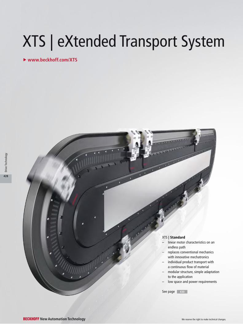
XTS | Standard– linear motor characteristics on an
endless path– replaces conventional mechanics
with innovative mechatronics– individual product transport with
a continuous flow of material– modular structure, simple adaptation
to the application– low space and power requirements
u www.beckhoff.com/XTS
XTS | eXtended Transport System
See page 430
We reserve the right to make technical changes.
428
Driv
e Te
chno
logy
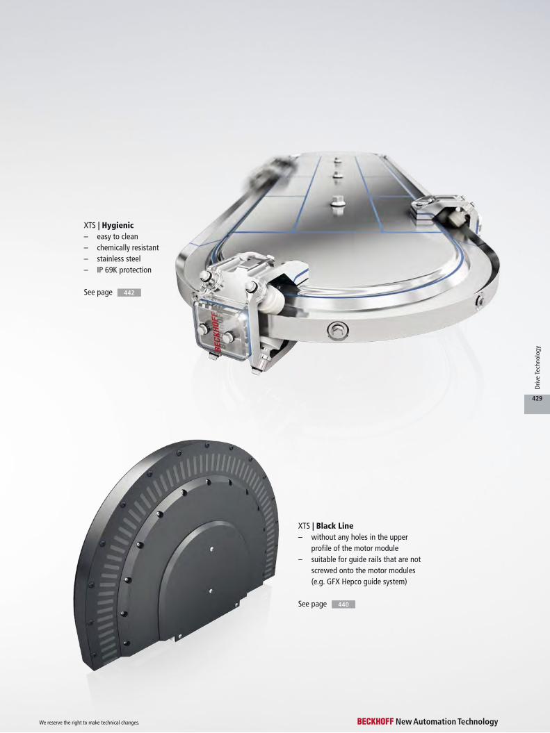
XTS | Hygienic– easy to clean– chemically resistant– stainless steel– IP 69K protection
See page 442
440See page
XTS | Black Line– without any holes in the upper
profile of the motor module– suitable for guide rails that are not
screwed onto the motor modules (e.g. GFX Hepco guide system)
We reserve the right to make technical changes.
429
Driv
e Te
chno
logy
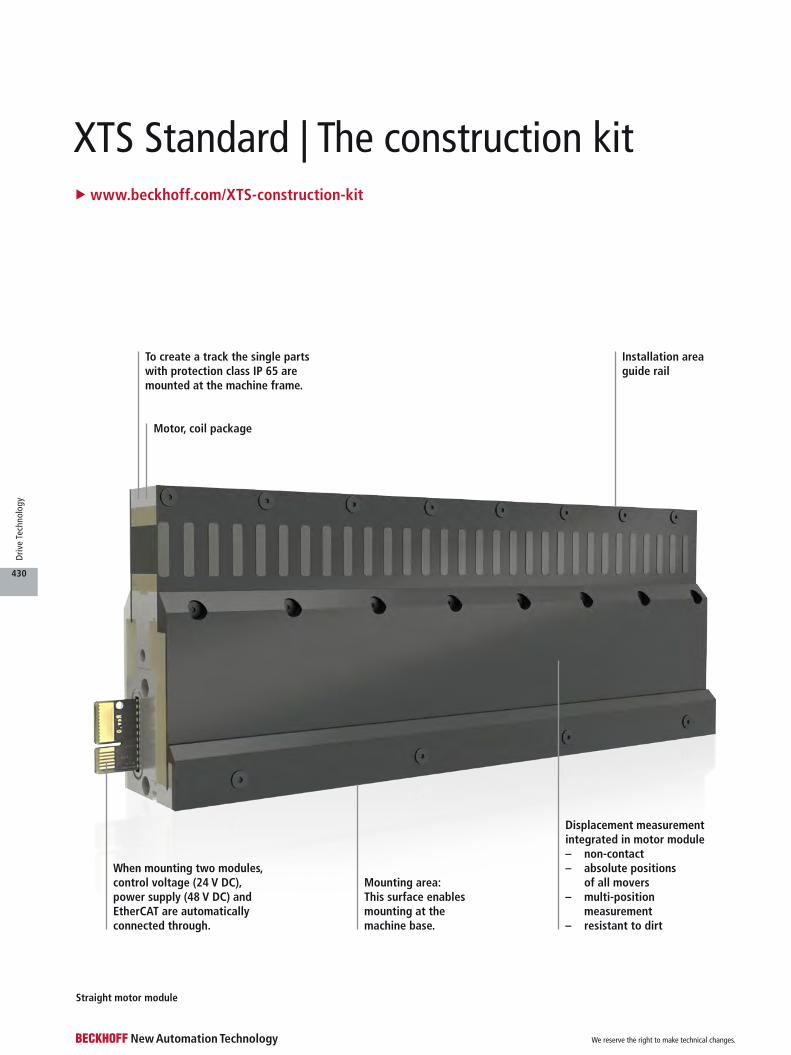
XTS Standard | The construction kitu www.beckhoff.com/XTS-construction-kit
When mounting two modules, control voltage (24 V DC), power supply (48 V DC) and EtherCAT are automatically connected through.
Mounting area: This surface enables mounting at the machine base.
Displacement measurement integrated in motor module – non-contact– absolute positions
of all movers– multi-position
measurement– resistant to dirt
Installation area guide rail
Straight motor module
Motor, coil package
To create a track the single parts with protection class IP 65 are mounted at the machine frame.
We reserve the right to make technical changes.
430
Driv
e Te
chno
logy
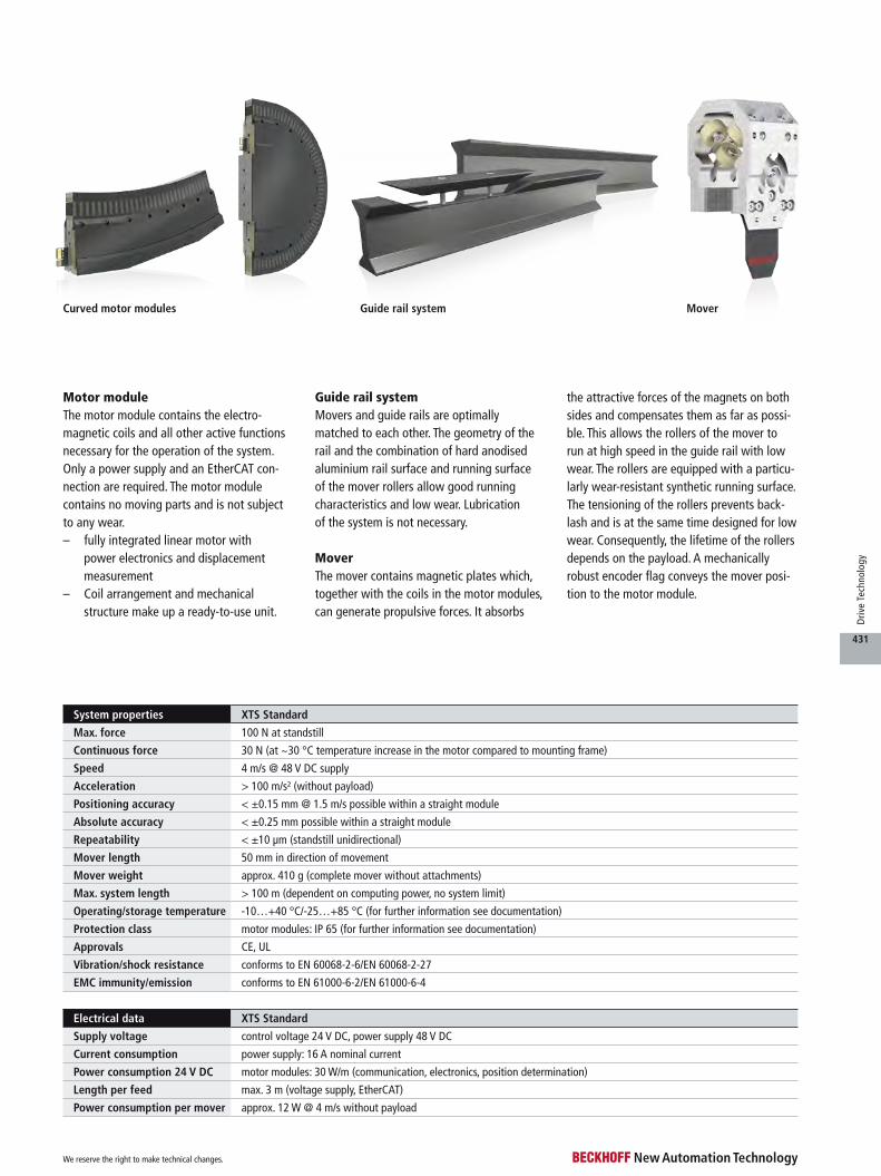
System properties XTS Standard
Max. force 100 N at standstill
Continuous force 30 N (at ~30 °C temperature increase in the motor compared to mounting frame)
Speed 4 m/s @ 48 V DC supply
Acceleration > 100 m/s² (without payload)
Positioning accuracy < ±0.15 mm @ 1.5 m/s possible within a straight module
Absolute accuracy < ±0.25 mm possible within a straight module
Repeatability < ±10 μm (standstill unidirectional)
Mover length 50 mm in direction of movement
Mover weight approx. 410 g (complete mover without attachments)
Max. system length > 100 m (dependent on computing power, no system limit)
Operating/storage temperature -10…+40 °C/-25…+85 °C (for further information see documentation)
Protection class motor modules: IP 65 (for further information see documentation)
Approvals CE, UL
Vibration/shock resistance conforms to EN 60068-2-6/EN 60068-2-27
EMC immunity/emission conforms to EN 61000-6-2/EN 61000-6-4
Electrical data XTS Standard
Supply voltage control voltage 24 V DC, power supply 48 V DC
Current consumption power supply: 16 A nominal current
Power consumption 24 V DC motor modules: 30 W/m (communication, electronics, position determination)
Length per feed max. 3 m (voltage supply, EtherCAT)
Power consumption per mover approx. 12 W @ 4 m/s without payload
Guide rail systemMovers and guide rails are optimally matched to each other. The geometry of the rail and the combination of hard anodised aluminium rail surface and running surface of the mover rollers allow good running characteristics and low wear. Lubrication of the system is not necessary.
MoverThe mover contains magnetic plates which, together with the coils in the motor modules, can generate propulsive forces. It absorbs
Motor moduleThe motor module contains the electro- magnetic coils and all other active functions necessary for the operation of the system. Only a power supply and an EtherCAT con-nection are required. The motor module contains no moving parts and is not subject to any wear.– fully integrated linear motor with
power electronics and displacement measurement
– Coil arrangement and mechanical structure make up a ready-to-use unit.
the attractive forces of the magnets on both sides and compensates them as far as possi-ble. This allows the rollers of the mover to run at high speed in the guide rail with low wear. The rollers are equipped with a particu-larly wear-resistant synthetic running surface. The tensioning of the rollers prevents back-lash and is at the same time designed for low wear. Consequently, the lifetime of the rollers depends on the payload. A mechanically robust encoder flag conveys the mover posi-tion to the motor module.
Curved motor modules Guide rail system Mover
We reserve the right to make technical changes.
431
Driv
e Te
chno
logy
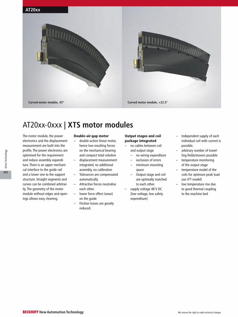
Curved motor module, +22.5°Curved motor module, 45°
The motor module, the power electronics and the displacement measurement are built into the profile. The power electronics are optimised for the requirement and reduce assembly expendi-ture. There is an upper mechani-cal interface to the guide rail and a lower one to the support structure. Straight segments and curves can be combined arbitrar-ily. The geometry of the motor module without edges and open-ings allows easy cleaning.
Double-air-gap motor– double-action linear motor,
hence low resulting forces on the mechanical bearing and compact total solution
– displacement measurement integrated, no additional assembly, no calibration
– Tolerances are compensated automatically.
– Attractive forces neutralise each other.
– lower force effect (wear) on the guide
– Friction losses are greatly reduced.
Output stages and coil package integrated– no cables between coil
and output stage– no wiring expenditure– exclusion of errors– minimum mounting
space– Output stage and coil
are optimally matched to each other.
– supply voltage 48 V DC (low voltage, low safety expenditure)
– Independent supply of each individual coil with current is possible.
– arbitrary number of travel-ling fields/movers possible
– temperature monitoring of the output stage
– temperature model of the coils for optimum peak load use (I²T model)
– low temperature rise due to good thermal coupling to the machine bed
AT20xx-0xxx | XTS motor modules
AT20xx
We reserve the right to make technical changes.
432
Driv
e Te
chno
logy
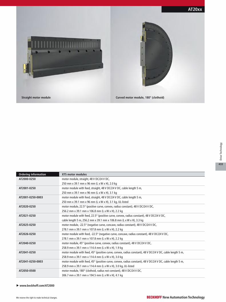
Curved motor module, 180° (clothoid)Straight motor module
in DE steht 3,3 kg – was ist richtig?
Ordering information XTS motor modules
AT2000-0250 motor module, straight, 48 V DC/24 V DC,
250 mm x 39.1 mm x 96 mm (L x W x H), 2.0 kg
AT2001-0250 motor module with feed, straight, 48 V DC/24 V DC, cable length 5 m,
250 mm x 39.1 mm x 96 mm (L x W x H), 3.1 kg
AT2001-0250-0003 motor module with feed, straight, 48 V DC/24 V DC, cable length 5 m,
250 mm x 39.1 mm x 96 mm (L x W x H), 3.1 kg, UL-listed
AT2020-0250 motor module, 22.5° (positive curve, convex, radius constant), 48 V DC/24 V DC,
256.2 mm x 39.1 mm x 106.8 mm (L x W x H), 2.2 kg
AT2021-0250 motor module with feed, 22.5° (positive curve, convex, radius constant), 48 V DC/24 V DC,
cable length 5 m, 256.2 mm x 39.1 mm x 106.8 mm (L x W x H), 3.3 kg
AT2025-0250 motor module, -22.5° (negative curve, concave, radius constant), 48 V DC/24 V DC,
278.1 mm x 39.1 mm x 107.8 mm (L x W x H), 2.2 kg
AT2026-0250 motor module with feed, -22.5° (negative curve, concave, radius constant), 48 V DC/24 V DC,
278.1 mm x 39.1 mm x 107.8 mm (L x W x H), 2.2 kg
AT2040-0250 motor module, 45° (positive curve, convex, radius constant), 48 V DC/24 V DC,
258.9 mm x 39.1 mm x 114.4 mm (L x W x H), 1.9 kg
AT2041-0250 motor module with feed, 45° (positive curve, convex, radius constant), 48 V DC/24 V DC, cable length 5 m,
258.9 mm x 39.1 mm x 114.4 mm (L x W x H), 3.0 kg
AT2041-0250-0003 motor module with feed, 45° (positive curve, convex, radius constant), 48 V DC/24 V DC, cable length 5 m,
258.9 mm x 39.1 mm x 114.4 mm (L x W x H), 3.0 kg, UL-listed
AT2050-0500 motor module, 180° (clothoid, radius not constant), 48 V DC/24 V DC,
306.7 mm x 39.1 mm x 194.5 mm (L x W x H), 4.1 kg
AT20xx
u www.beckhoff.com/AT2000
We reserve the right to make technical changes.
433
Driv
e Te
chno
logy

Retainer for magnetic plate and rollers
Encoder flag fordisplacement measurement
Rollers
Magnetic plates
AT9012AT9011
u www.beckhoff.com/AT9011
The magnetic plates can also be procured separately in order to be able to fit them to a self-developed mover.
Technical boundary conditions and support on enquiry.
The movers are made of a light and solid aluminium alloy. Thanks to their arrangement the rollers allow backlash-free travel on the straights and in the curves. The coating of the rollers causes very little running noise and is particularly low-wear without lubrication of the guide rail. The attractive forces of the magnetic plates are largely balanced by the opposed arrangement, so that the rollers and the rail do not have to absorb the compara-
tively high attractive forces of the magnets.
The centre of the encoder flag supplies a position signal to the motor module. A Mover 1 can be detected by means of a special magnetic plate set. The encoder flag is made from a sturdy, lightweight glass-fibre reinforced material.
The AT9011-0070-0550 mover provides an increased payload due to its overall length of 70 mm and larger rollers. The standard rail can be used
for traveling in straight lines, adapted rails are necessary for traveling around corners. Therefore, a mixed operation of movers of different sizes is only possible when traveling in straight lines.
Features– no sliding contacts or
cables to the moved part, purely passive mover
– 2 magnetic plates generate the controlled propulsive force via the motor module.
– The attractive forces largely neutralise each other in relation to the guide mechanism.
– low friction losses – An encoder flag generates
the position signal.– Short mover length allows
small product spacings.– Geometry allows driving
through curves with full dynamics.
– no development of heat on and in the mover
AT9011, AT9012 | XTS movers
AT9011, AT9012
Ordering information XTS mover suitable for the guide rail system AT9000/AT9050
AT9011-0050-0550 mover, 6 rollers (plastic coated), length 50 mm, 410 g,
mounted with magnetic plate set AT9001-0550 and set of rollers ZX9011-0050
AT9011-0050-1550 mover, 6 rollers (plastic coated), length 50 mm, 410 g,
mounted with magnetic plate set AT9001-1550 and set of rollers ZX9011-0050
AT9011-0070-0550 mover, 6 rollers (plastic coated), length 70 mm, 595 g,
mounted with magnetic plate set AT9001-0550 and set of rollers ZX9011-0070
AT9011-0070-1550 mover, 6 rollers (plastic coated), length 70 mm, 595 g,
mounted with magnetic plate set AT9001-1550 and set of rollers ZX9011-0070
AT9012-0050-0550 mover, 12 rollers (plastic coated), length 50 mm, 460 g,
mounted with magnetic plate set AT9001-0550 and set of rollers ZX9012-0050
AT9012-0050-1550 mover, 12 rollers (plastic coated), length 50 mm, 460 g,
mounted with magnetic plate set AT9001-1550 and set of rollers ZX9012-0050
We reserve the right to make technical changes.
434
Driv
e Te
chno
logy
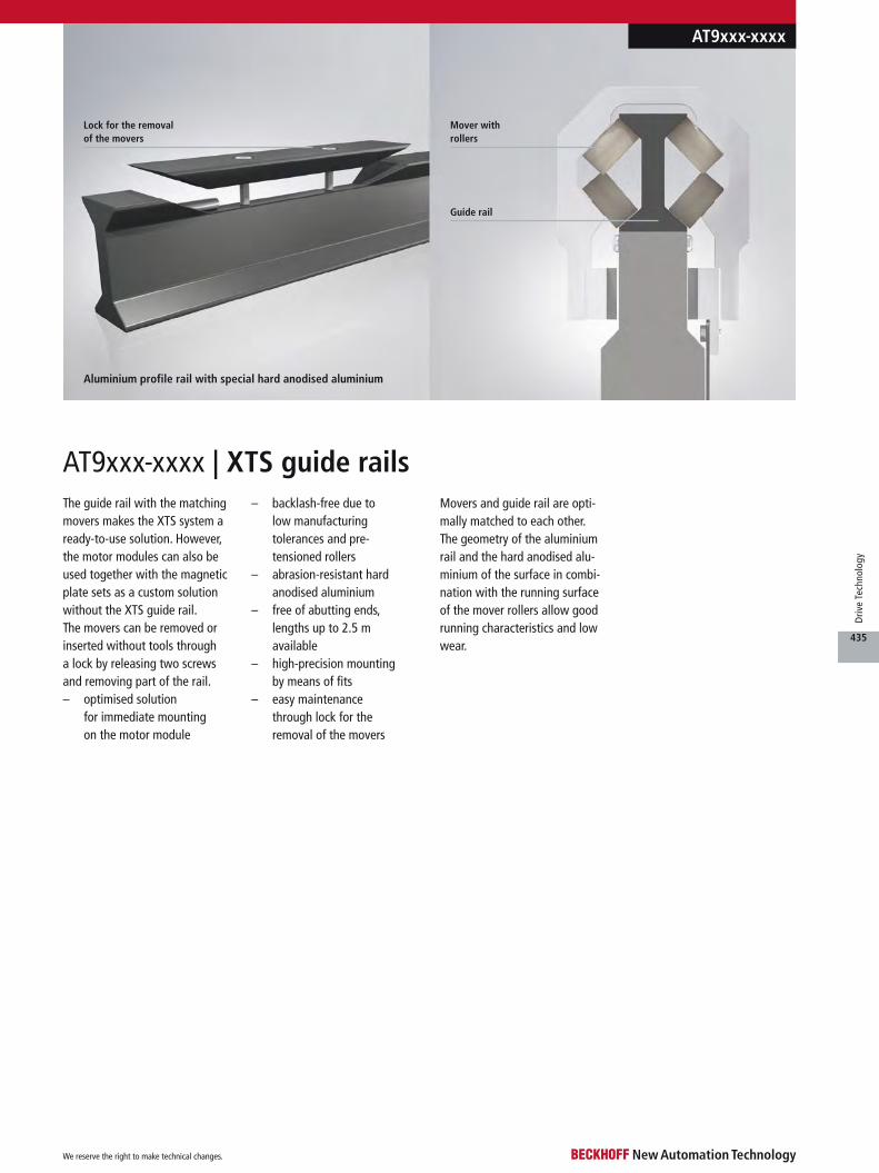
Mover with rollers
Aluminium profile rail with special hard anodised aluminium
Guide rail
Lock for the removal of the movers
AT9xxx-xxxx | XTS guide railsThe guide rail with the matching movers makes the XTS system a ready-to-use solution. However, the motor modules can also be used together with the magnetic plate sets as a custom solution without the XTS guide rail. The movers can be removed or inserted without tools through a lock by releasing two screws and removing part of the rail.– optimised solution
for immediate mounting on the motor module
– backlash-free due to low manufacturing tolerances and pre- tensioned rollers
– abrasion-resistant hard anodised aluminium
– free of abutting ends, lengths up to 2.5 m available
– high-precision mounting by means of fits
– easy maintenance through lock for the removal of the movers
Movers and guide rail are opti-mally matched to each other. The geometry of the aluminium rail and the hard anodised alu-minium of the surface in combi-nation with the running surface of the mover rollers allow good running characteristics and low wear.
AT9xxx-xxxx
We reserve the right to make technical changes.
435
Driv
e Te
chno
logy
Ordering information XTS guide rails, suitable for straight motor modules
AT9000-0250 guide rail, 250 mm, straight, suitable for 1 x straight motor module AT200x-0250 with/without feed
AT9000-0500 guide rail, 500 mm, straight, suitable for 2 x straight motor module AT200x-0250 with/without feed
AT9000-0750 guide rail, 750 mm, straight, suitable for 3 x straight motor module AT200x-0250 with/without feed
AT9000-1000 guide rail, 1000 mm, straight, suitable for 4 x straight motor module AT200x-0250 with/without feed
AT9000-1250 guide rail, 1250 mm, straight, suitable for 5 x straight motor module AT200x-0250 with/without feed
AT9000-1500 guide rail, 1500 mm, straight, suitable for 6 x straight motor module AT200x-0250 with/without feed
AT9000-1750 guide rail, 1750 mm, straight, suitable for 7 x straight motor module AT200x-0250 with/without feed
AT9000-2000 guide rail, 2000 mm, straight, suitable for 8 x straight motor module AT200x-0250 with/without feed
AT9000-2250 guide rail, 2250 mm, straight, suitable for 9 x straight motor module AT200x-0250 with/without feed
AT9000-2500 guide rail, 2500 mm, straight, suitable for 10 x straight motor module AT200x-0250 with/without feed
Ordering information XTS guide rails, suitable for 22.5° motor modules
AT9020-0500 guide rail, 500 mm, 22.5° curve (positive curve, convex, radius constant),
for AT9011-0050-xxxx, suitable for 1 x straight motor module AT200x-0250
with/without feed and 1 x 22.5° motor module AT202x-0250 with/without feed
AT9020-2250 guide rail set, 2250 mm, 180° curve (positive curve, convex, radius constant, 2 parts),
for AT9011-0050-xxxx, consisting of 1 x AT9020-2250-1050 guide rail, 1250 mm, 90° curve,
suitable for 1 x straight motor module AT200x-0250 with/without feed and 4 x 22.5° motor
module AT202x-0250 with/without feed 1 x AT9020-2250-2050 guide rail, 1000 mm, 90° curve,
suitable for 4 x 22.5° motor module AT202x-0250 with/without feed
AT9020-2250-0070 guide rail set, 2250 mm, 180° curve (positive curve, convex, radius constant, 2 parts),
for AT9011-0070-xxxx, consisting of 1 x AT9020-2250-1070 guide rail, 1250 mm, 90° curve,
suitable for 1 x straight motor module AT200x-0250 with/without feed and 4 x 22.5° motor
module AT202x-0250 with/without feed 1 x AT9020-2250-2070 guide rail, 1000 mm, 90° curve,
suitable for 4 x 22.5° motor module AT202x-0250 with/without feed
Ordering information XTS guide rails with gate, suitable for straigth motor modules
AT9100-0250 guide rail, 250 mm, straight with gate, suitable for 1 x straight motor module AT200x-0250 with/without feed
AT9100-0500 guide rail, 500 mm, straight with gate, suitable for 2 x straight motor module AT200x-0250 with/without feed
AT9100-0750 guide rail, 750 mm, straight with gate, suitable for 3 x straight motor module AT200x-0250 with/without feed
AT9100-1000 guide rail, 1000 mm, straight with gate, suitable for 4 x straight motor module AT200x-0250 with/without feed
AT9100-1250 guide rail, 1250 mm, straight with gate, suitable for 5 x straight motor module AT200x-0250 with/without feed
AT9100-1500 guide rail, 1500 mm, straight with gate, suitable for 6 x straight motor module AT200x-0250 with/without feed
AT9100-1750 guide rail, 1750 mm, straight with gate, suitable for 7 x straight motor module AT200x-0250 with/without feed
AT9100-2000 guide rail, 2000 mm, straight with gate, suitable for 8 x straight motor module AT200x-0250 with/without feed
AT9100-2250 guide rail, 2550 mm, straight with gate, suitable for 9 x straight motor module AT200x-0250 with/without feed
AT9100-2500 guide rail, 2500 mm, straight with gate, suitable for 10 x straight motor module AT200x-0250 with/without feed
AT9xxx-xxxx
We reserve the right to make technical changes.
436
Driv
e Te
chno
logy
u www.beckhoff.com/AT9000
Ordering information XTS guide rails, suitable for -22.5° motor modules
AT9025-0500 guide rail, 500 mm, -22.5° curve (negative curve, concave, radius constant),
for AT9011-0050-xxxx, suitable for 1 x straight motor module AT200x-0250
with/without feed and 1 x -22.5° motor module AT202x-0250 with/without feed
Ordering information XTS guide rails, suitable for 180° motor modules (clothoid)
AT9050-0500 guide rail, 500 mm, 180° curve (clothoid, radius not constant),
for AT9011-0050-xxxx or AT9012-0050-xxxx, suitable for 1 x 180° motor module AT2050-0500
AT9050-0500-0070 guide rail, 500 mm, 180° curve (clothoid, radius not constant),
for AT9011-0070-xxxx, suitable for 1 x 180° motor module AT2050-0500
AT9xxx-xxxx
Ordering information XTS guide rails, suitable for 45° motor modules
AT9040-0500 guide rail, 500 mm, 45° curve (positive curve, convex, radius constant),
for AT9011-0050-xxxx, suitable for 1 x straight motor module AT200x-0250
with/without feed and 1 x 45° motor module AT204x-0250 with/without feed
AT9040-0750 guide rail, 750 mm, 90° curve (positive curve, convex, radius constant),
for AT9011-0050-xxxx, suitable for 1 x straight motor module AT200x-0250
with/without feed and 2 x 45° motor module AT204x-0250 with/without feed
AT9040-0750-0070 guide rail, 750 mm, 90° curve (positive curve, convex, radius constant),
for AT9011-0070-xxxx, suitable for 1 x straight motor module AT200x-0250
with/without feed and 2 x 45° motor module AT204x-0250 with/without feed
AT9040-1250 guide rail set, 1250 mm, 180° curve (positive curve, convex, radius constant, 2 parts),
for AT9011-0050-xxxx, consisting of 1 x AT9040-1250-1050 guide rail, 750 mm,
90° curve, suitable for 1 x straight motor module AT200x-0250 with/without feed
and 2 x 45° motor module AT204x-0250 with/without feed 1 x AT9040-1250-2050 guide rail,
500 mm, 90° curve, suitable for 2 x 45° motor module AT204x-0250 with/without feed
AT9040-1250-0070 guide rail set, 1250 mm, 180° curve (positive curve, convex, radius constant, 2 parts),
for AT9011-0070-xxxx, consisting of 1 x AT9040-1250-1070 guide rail, 750 mm,
90° curve, suitable for 1 x straight motor module AT200x-0250 with/without feed
and 2 x 45° motor module AT204x-0250 with/without feed 1 x AT9040-1250-2070 guide rail,
500 mm, 90° curve, suitable for 2 x 45° motor module AT204x-0250 with/without feed
AT9142-2000 guide rail set, 2000 mm, 360° circle (positive curve, convex, radius constant, 4 parts),
for AT9011-0050-xxxx, consisting of 1 x AT9142-2000-1050 guide rail, 500 mm,
90° curve with gate, suitable for 2 x 45° motor module AT204x-0250 with/without feed
3 x AT9142-2000-2050 guide rail, 500 mm, 90° curve, suitable for 2 x 45° motor module
AT204x-0250 with/without feed
We reserve the right to make technical changes.
437
Driv
e Te
chno
logy
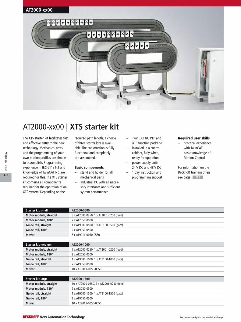
The XTS starter kit facilitates fast and effective entry to the new technology. Mechanical tests and the programming of your own motion profiles are simple to accomplish. Programming experience in IEC 61131-3 and knowledge of TwinCAT NC are required for this. The XTS starter kit contains all components required for the operation of an XTS system. Depending on the
required path length, a choice of three starter kits is avail- able. The construction is fully functional and completely pre-assembled.
Basic components– stand and holder for all
mechanical parts– Industrial PC with all neces-
sary interfaces and sufficient system performance
– TwinCAT NC PTP and XTS function package
– installed in a control cabinet, fully wired, ready for operation
– power supply units 24 V DC and 48 V DC
– 1 day instruction and programming support
Required user skills– practical experience
with TwinCAT– basic knowledge of
Motion Control
AT2000-xx00 | XTS starter kit
For information on the Beckhoff training offers see page 572
Starter kit small AT2000-0500
Motor module, straight 3 x AT2000-0250, 1 x AT2001-0250 (feed)
Motor module, 180° 2 x AT2050-0500
Guide rail, straight 1 x AT9000-0500, 1 x AT9100-0500 (gate)
Guide rail, 180° 2 x AT9050-0500
Mover 5 x AT9011-0050-0550
Starter kit medium AT2000-1000
Motor module, straight 7 x AT2000-0250, 1 x AT2001-0250 (feed)
Motor module, 180° 2 x AT2050-0500
Guide rail, straight 1 x AT9000-1000, 1 x AT9100-1000 (gate)
Guide rail, 180° 2 x AT9050-0500
Mover 10 x AT9011-0050-0550
Starter kit large AT2000-1500
Motor module, straight 10 x AT2000-0250, 2 x AT2001-0250 (feed)
Motor module, 180° 2 x AT2050-0500
Guide rail, straight 1 x AT9000-1500, 1 x AT9100-1500 (gate)
Guide rail, 180° 2 x AT9050-0500
Mover 10 x AT9011-0050-0550
AT2000-xx00
We reserve the right to make technical changes.
438
Driv
e Te
chno
logy
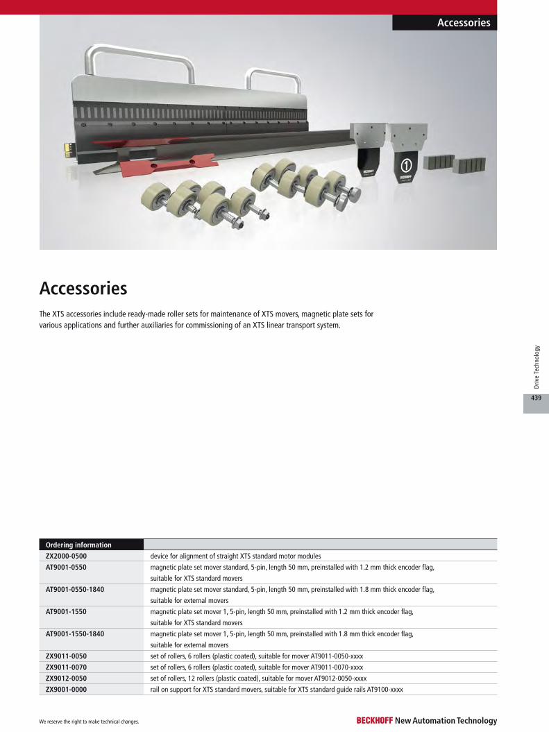
Ordering information
ZX2000-0500 device for alignment of straight XTS standard motor modules
AT9001-0550 magnetic plate set mover standard, 5-pin, length 50 mm, preinstalled with 1.2 mm thick encoder flag,
suitable for XTS standard movers
AT9001-0550-1840 magnetic plate set mover standard, 5-pin, length 50 mm, preinstalled with 1.8 mm thick encoder flag,
suitable for external movers
AT9001-1550 magnetic plate set mover 1, 5-pin, length 50 mm, preinstalled with 1.2 mm thick encoder flag,
suitable for XTS standard movers
AT9001-1550-1840 magnetic plate set mover 1, 5-pin, length 50 mm, preinstalled with 1.8 mm thick encoder flag,
suitable for external movers
ZX9011-0050 set of rollers, 6 rollers (plastic coated), suitable for mover AT9011-0050-xxxx
ZX9011-0070 set of rollers, 6 rollers (plastic coated), suitable for mover AT9011-0070-xxxx
ZX9012-0050 set of rollers, 12 rollers (plastic coated), suitable for mover AT9012-0050-xxxx
ZX9001-0000 rail on support for XTS standard movers, suitable for XTS standard guide rails AT9100-xxxx
Accessories
Accessories
The XTS accessories include ready-made roller sets for maintenance of XTS movers, magnetic plate sets for various applications and further auxiliaries for commissioning of an XTS linear transport system.
We reserve the right to make technical changes.
439
Driv
e Te
chno
logy
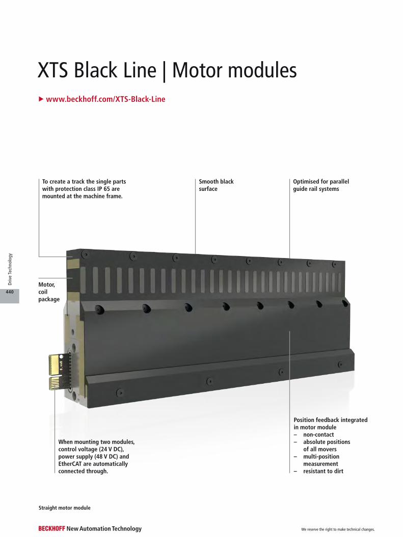
u www.beckhoff.com/XTS-Black-Line
XTS Black Line | Motor modules
Straight motor module
Motor, coil package
To create a track the single parts with protection class IP 65 are mounted at the machine frame.
When mounting two modules, control voltage (24 V DC), power supply (48 V DC) and EtherCAT are automatically connected through.
Optimised for parallel guide rail systems
Smooth black surface
Position feedback integrated in motor module– non-contact– absolute positions
of all movers– multi-position
measurement– resistant to dirt
We reserve the right to make technical changes.
440
Driv
e Te
chno
logy
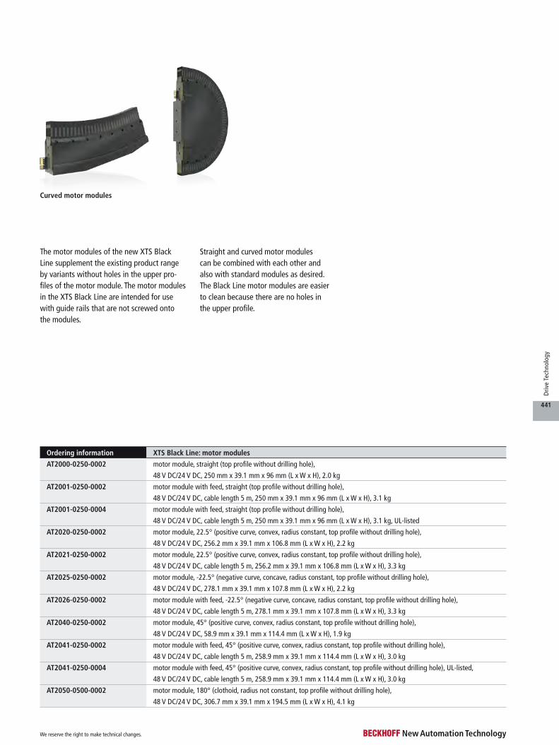
Curved motor modules
The motor modules of the new XTS Black Line supplement the existing product range by variants without holes in the upper pro-files of the motor module. The motor modules in the XTS Black Line are intended for use with guide rails that are not screwed onto the modules.
Straight and curved motor modules can be combined with each other and also with standard modules as desired. The Black Line motor modules are easier to clean because there are no holes in the upper profile.
Ordering information XTS Black Line: motor modules
AT2000-0250-0002 motor module, straight (top profile without drilling hole),
48 V DC/24 V DC, 250 mm x 39.1 mm x 96 mm (L x W x H), 2.0 kg
AT2001-0250-0002 motor module with feed, straight (top profile without drilling hole),
48 V DC/24 V DC, cable length 5 m, 250 mm x 39.1 mm x 96 mm (L x W x H), 3.1 kg
AT2001-0250-0004 motor module with feed, straight (top profile without drilling hole),
48 V DC/24 V DC, cable length 5 m, 250 mm x 39.1 mm x 96 mm (L x W x H), 3.1 kg, UL-listed
AT2020-0250-0002 motor module, 22.5° (positive curve, convex, radius constant, top profile without drilling hole),
48 V DC/24 V DC, 256.2 mm x 39.1 mm x 106.8 mm (L x W x H), 2.2 kg
AT2021-0250-0002 motor module, 22.5° (positive curve, convex, radius constant, top profile without drilling hole),
48 V DC/24 V DC, cable length 5 m, 256.2 mm x 39.1 mm x 106.8 mm (L x W x H), 3.3 kg
AT2025-0250-0002 motor module, -22.5° (negative curve, concave, radius constant, top profile without drilling hole),
48 V DC/24 V DC, 278.1 mm x 39.1 mm x 107.8 mm (L x W x H), 2.2 kg
AT2026-0250-0002 motor module with feed, -22.5° (negative curve, concave, radius constant, top profile without drilling hole),
48 V DC/24 V DC, cable length 5 m, 278.1 mm x 39.1 mm x 107.8 mm (L x W x H), 3.3 kg
AT2040-0250-0002 motor module, 45° (positive curve, convex, radius constant, top profile without drilling hole),
48 V DC/24 V DC, 58.9 mm x 39.1 mm x 114.4 mm (L x W x H), 1.9 kg
AT2041-0250-0002 motor module with feed, 45° (positive curve, convex, radius constant, top profile without drilling hole),
48 V DC/24 V DC, cable length 5 m, 258.9 mm x 39.1 mm x 114.4 mm (L x W x H), 3.0 kg
AT2041-0250-0004 motor module with feed, 45° (positive curve, convex, radius constant, top profile without drilling hole), UL-listed,
48 V DC/24 V DC, cable length 5 m, 258.9 mm x 39.1 mm x 114.4 mm (L x W x H), 3.0 kg
AT2050-0500-0002 motor module, 180° (clothoid, radius not constant, top profile without drilling hole),
48 V DC/24 V DC, 306.7 mm x 39.1 mm x 194.5 mm (L x W x H), 4.1 kg
We reserve the right to make technical changes.
441
Driv
e Te
chno
logy

Straight motor module
XTS Hygienic | The construction kitu www.beckhoff.com/XTS-Hygienic
When mounting two modules, control voltage (24 V DC), power supply (48 V DC) and EtherCAT are automatically connected through.
Mounting area: This surface enables mounting at the machine base.
Position feedback integrated in motor module– non-contact– absolute positions
of all movers– multi-position
measurement– resistant to dirt
Installation areaguide rail
Centering hole
To create a track the single parts with protection class IP 69K are mounted at the machine frame.
Circumferential seals prevent the ingress of dirt particles.
We reserve the right to make technical changes.
442
Driv
e Te
chno
logy

The fully encapsulated mechatronic trans-port system, XTS Hygienic combines the advantages of rotary and linear drive systems for demanding environmental conditions. The stainless steel version of the XTS linear transport system (with IP 69K protection rat-ing) provides all functions required for system operation:– modular, fully integrated linear motor
combines power electronics and position feedback in a single component
– multiple movers used as moved parts for controlling the material flow
– mechanical guide rails for configuration of any desired geometry
With this matching set of only a few compo-nents, the most diverse applications in the food and pharmaceutical industries can be realised. All surfaces are chemically resis- tant and provide ease of cleaning. A system implementation with XTS Hygienic offers hygienic design without any hidden edges
or undercuts. All components are sealed at the joints with a high-quality elastic material and enable high-pressure wash-down. As a result, the XTS Hygienic meets all EHEDG requirements for system certifica-tion according to EL Class I AUX. Due to the reduced construction volume of the XTS components, users benefit from a smaller machine footprint in a clear layout providing ease of maintenance.
System properties XTS Hygienic
Max. force 90 N at standstill
Continuous force 30 N (at ~30 °C temperature increase in the motor compared to mounting frame)
Speed 4 m/s @ 48 V DC supply
Acceleration > 50 m/s² (without payload)
Mover length 80 mm in direction of movement
Mover weight approx. 910 g (complete mover without attachments)
Max. system length > 100 m (dependent on computing power, no system limit)
Surface electropolished
Material housing: stainless steel 1.4404 AISI 316L; sealing: FPM
Operating/storage temperature -10…+40 °C/-25…+85 °C (for further information see documentation)
Protection class IP 69K
Approvals CE, EHEDG EL Class I AUX (standard-compliant when assembled)
Vibration/shock resistance conforms to EN 60068-2-6/EN 60068-2-27
EMC immunity/emission conforms to EN 61000-6-2/EN 61000-6-4
Electrical data XTS Hygienic
Supply voltage control voltage 24 V DC, power supply 48 V DC
Current consumption power supply: 16 A nominal current
Power consumption 24 V DC motor modules: 30 W/m (communication, electronics, position determination)
Length per feed max. 3 m (voltage supply, EtherCAT)
Power consumption per mover approx. 15 W @ 4 m/s without payload
Curved motor module Guide rail system Mover
We reserve the right to make technical changes.
443
Driv
e Te
chno
logy

Technical data ATH2000-0250 ATH2001-0250 ATH2050-0500
Infeed – yes –
Design form straight straight curved
Dimensions (L x W x H) 250 mm x 34 mm x 96 mm 250 mm x 34 mm x 96 mm 315 mm x 34 mm x 200 mm
Weight 4.0 kg 5.4 kg 8.0 kg
Surface electropolished
Material housing: stainless steel 1.4404 AISI 316L; sealing: FPM
Protection class IP 69K
Approvals CE
Ordering information XTS Hygienic: stainless steel motor modules
ATH2000-0250 stainless steel motor module, straight, 48 V DC/24 V DC, protection class IP 69K,
250 mm x 34 mm x 96 mm (L x W x H), 4.0 kg
ATH2001-0250 stainless steel motor module with feed, straight, 48 V DC/24 V DC, cable length 5 m, protection class IP 69K,
250 mm x 34 mm x 96 mm (L x W x H), 5.4 kg
ATH2050-0500 stainless steel motor module, 180° (clothoid, radius not constant), 48 V DC/24 V DC, protection class IP 69K,
315 mm x 34 mm x 200 mm (L x W x H), 8.0 kg
For availability status see Beckhoff website at: www.beckhoff.com/ATH2000
u www.beckhoff.com/ATH2000
ATH2000 | XTS Hygienic motor modulesThe motor modules of the new XTS Hygienic series combine the advantages of the XTS and com-pliance with the high require-ments of the food industry in relation to media resistance and easy cleaning.
Power electronics and posi-tion feedback are integrated in an electropolished stainless steel housing made of 1.4404 AISI 316L and are ready to connect.
When assembled, the motor modules seal to the machine bed and the guide rails without leav-ing any gaps or dead spaces. The required FPM seals are a fixed part of the housing, considerably simplifying system assembly. As usual, all motor modules can be combined with as desired. In the assembled state, compliance with protec-tion class IP 69K is ensured.
The XTS components in hygienic design meet the requirements of the EHEDG recommenda-tion with regard to cleanability and sealing. Certification of a system into which XTS Hygienic components are installed is pos-sible according to the “Hygienic Design Weihenstephan Certified System”.
The ATH2050-0500 curved modules can be connected to the
straight modules ATH2000-0250 or ATH2001-0250. By adding two curved modules, a closed circuit track can be designed with the movers running on the circumference. To ensure the high IP 69K protection rating, the system is completely sealed.
ATH2000
We reserve the right to make technical changes.
444
Driv
e Te
chno
logy
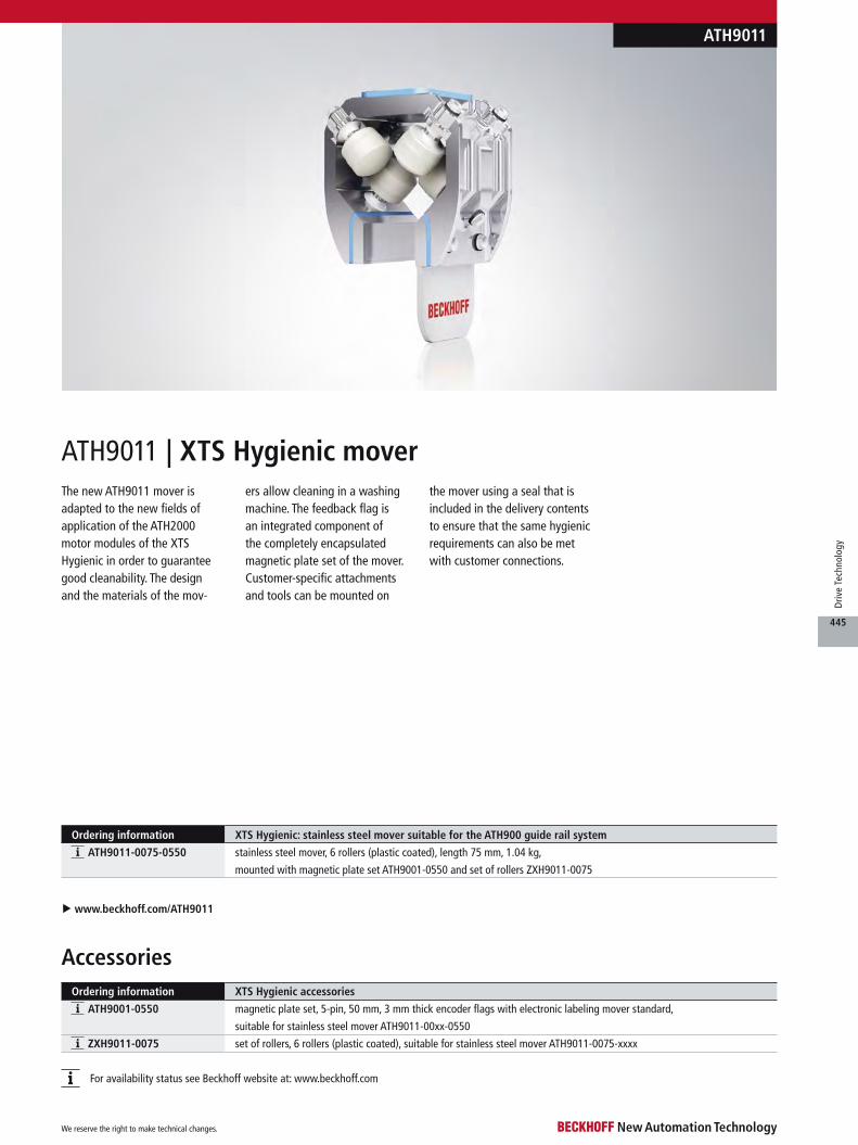
u www.beckhoff.com/ATH9011
Ordering information XTS Hygienic: stainless steel mover suitable for the ATH900 guide rail system
ATH9011-0075-0550 stainless steel mover, 6 rollers (plastic coated), length 75 mm, 1.04 kg,
mounted with magnetic plate set ATH9001-0550 and set of rollers ZXH9011-0075
The new ATH9011 mover is adapted to the new fields of application of the ATH2000 motor modules of the XTS Hygienic in order to guarantee good cleanability. The design and the materials of the mov-
ers allow cleaning in a washing machine. The feedback flag is an integrated component of the completely encapsulated magnetic plate set of the mover. Customer-specific attachments and tools can be mounted on
the mover using a seal that is included in the delivery contents to ensure that the same hygienic requirements can also be met with customer connections.
ATH9011 | XTS Hygienic mover
For availability status see Beckhoff website at: www.beckhoff.com
ATH9011
Ordering information XTS Hygienic accessories
ATH9001-0550 magnetic plate set, 5-pin, 50 mm, 3 mm thick encoder flags with electronic labeling mover standard,
suitable for stainless steel mover ATH9011-00xx-0550
ZXH9011-0075 set of rollers, 6 rollers (plastic coated), suitable for stainless steel mover ATH9011-0075-xxxx
Accessories
We reserve the right to make technical changes.
445
Driv
e Te
chno
logy
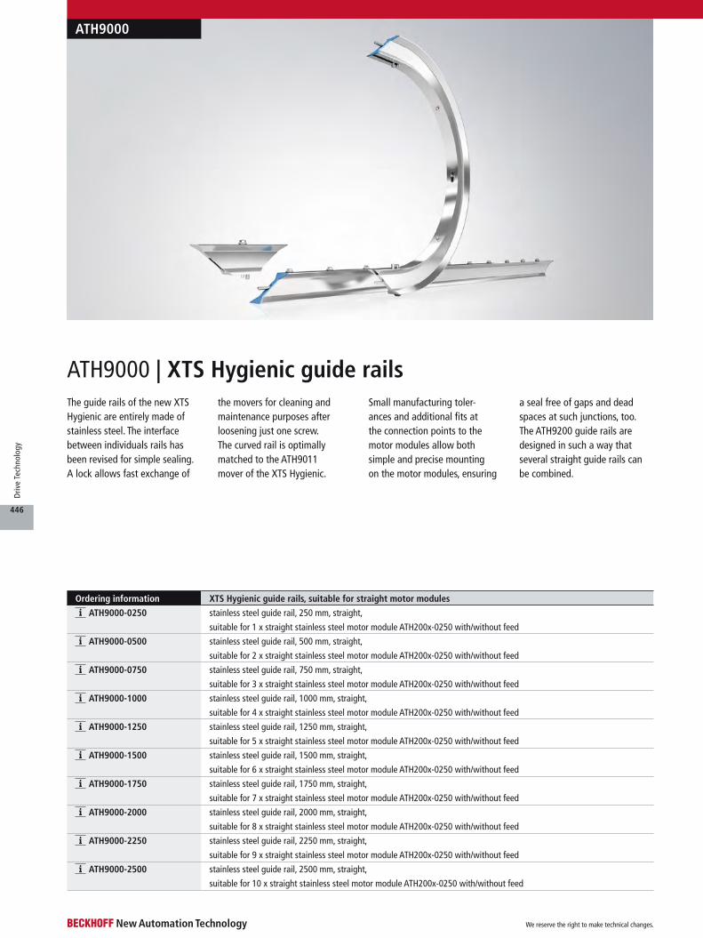
Ordering information XTS Hygienic guide rails, suitable for straight motor modules
ATH9000-0250 stainless steel guide rail, 250 mm, straight,
suitable for 1 x straight stainless steel motor module ATH200x-0250 with/without feed
ATH9000-0500 stainless steel guide rail, 500 mm, straight,
suitable for 2 x straight stainless steel motor module ATH200x-0250 with/without feed
ATH9000-0750 stainless steel guide rail, 750 mm, straight,
suitable for 3 x straight stainless steel motor module ATH200x-0250 with/without feed
ATH9000-1000 stainless steel guide rail, 1000 mm, straight,
suitable for 4 x straight stainless steel motor module ATH200x-0250 with/without feed
ATH9000-1250 stainless steel guide rail, 1250 mm, straight,
suitable for 5 x straight stainless steel motor module ATH200x-0250 with/without feed
ATH9000-1500 stainless steel guide rail, 1500 mm, straight,
suitable for 6 x straight stainless steel motor module ATH200x-0250 with/without feed
ATH9000-1750 stainless steel guide rail, 1750 mm, straight,
suitable for 7 x straight stainless steel motor module ATH200x-0250 with/without feed
ATH9000-2000 stainless steel guide rail, 2000 mm, straight,
suitable for 8 x straight stainless steel motor module ATH200x-0250 with/without feed
ATH9000-2250 stainless steel guide rail, 2250 mm, straight,
suitable for 9 x straight stainless steel motor module ATH200x-0250 with/without feed
ATH9000-2500 stainless steel guide rail, 2500 mm, straight,
suitable for 10 x straight stainless steel motor module ATH200x-0250 with/without feed
The guide rails of the new XTS Hygienic are entirely made of stainless steel. The interface between individuals rails has been revised for simple sealing. A lock allows fast exchange of
the movers for cleaning and maintenance purposes after loosening just one screw. The curved rail is optimally matched to the ATH9011 mover of the XTS Hygienic.
Small manufacturing toler- ances and additional fits at the connection points to the motor modules allow both simple and precise mounting on the motor modules, ensuring
a seal free of gaps and dead spaces at such junctions, too. The ATH9200 guide rails are designed in such a way that several straight guide rails can be combined.
ATH9000 | XTS Hygienic guide rails
ATH9000
We reserve the right to make technical changes.
446
Driv
e Te
chno
logy

Ordering information XTS Hygienic guide rails, suitable for 180° motor modules (clothoid)
ATH9050-0500-0075 stainless steel guide rail, 500 mm, 180° curve (clothoid, radius not constant), for ATH901x-0075-0550,
suitable for 1 x stainless steel motor module ATH2050-0500
Ordering information XTS Hygienic guide rails with gate, suitable for straight motor modules
ATH9100-0500 stainless steel guide rail, 500 mm, straight with gate,
suitable for 2 x straight stainless steel motor module ATH200x-0250 with/without feed
ATH9100-0750 stainless steel guide rail, 750 mm, straight with gate,
suitable for 3 x straight stainless steel motor module ATH200x-0250 with/without feed
ATH9100-1000 stainless steel guide rail, 1000 mm, straight with gate,
suitable for 4 x straight stainless steel motor module ATH200x-0250 with/without feed
ATH9100-1250 stainless steel guide rail, 1250 mm, straight with gate,
suitable for 5 x straight stainless steel motor module ATH200x-0250 with/without feed
ATH9100-1500 stainless steel guide rail, 1500 mm, straight with gate,
suitable for 6 x straight stainless steel motor module ATH200x-0250 with/without feed
ATH9100-1750 stainless steel guide rail, 1750 mm, straight with gate,
suitable for 7 x straight stainless steel motor module ATH200x-0250 with/without feed
ATH9100-2000 stainless steel guide rail, 2000 mm, straight with gate,
suitable for 8 x straight stainless steel motor module ATH200x-0250 with/without feed
ATH9100-2250 stainless steel guide rail, 2250 mm, straight with gate,
suitable for 9 x straight stainless steel motor module ATH200x-0250 with/without feed
ATH9100-2500 stainless steel guide rail, 2500 mm, straight with gate,
suitable for 10 x straight stainless steel motor module ATH200x-0250 with/without feed
Ordering information XTS Hygienic guide rails, connectors
ATH9200-0250 stainless steel guide rail, 250 mm, connector for straight stainless steel guide rails,
suitable for 1 x straight stainless steel motor module ATH200x-0250 with/without feed
ATH9200-0500 stainless steel guide rail, 500 mm, connector for straight stainless steel guide rails,
suitable for 2 x straight stainless steel motor module ATH200x-0250 with/without feed
ATH9200-0750 stainless steel guide rail, 750 mm, connector for straight stainless steel guide rails,
suitable for 3 x straight stainless steel motor module ATH200x-0250 with/without feed
ATH9200-1000 stainless steel guide rail, 1000 mm, connector for straight stainless steel guide rails,
suitable for 4 x straight stainless steel motor module ATH200x-0250 with/without feed
ATH9200-1250 stainless steel guide rail, 1250 mm, connector for straight stainless steel guide rails,
suitable for 5 x straight stainless steel motor module ATH200x-0250 with/without feed
ATH9200-1500 stainless steel guide rail, 1500 mm, connector for straight stainless steel guide rails,
suitable for 6 x straight stainless steel motor module ATH200x-0250 with/without feed
ATH9200-1750 stainless steel guide rail, 1750 mm, connector for straight stainless steel guide rails,
suitable for 7 x straight stainless steel motor module ATH200x-0250 with/without feed
ATH9200-2000 stainless steel guide rail, 2000 mm, connector for straight stainless steel guide rails,
suitable for 8 x straight stainless steel motor module ATH200x-0250 with/without feed
ATH9200-2250 stainless steel guide rail, 2250 mm, connector for straight stainless steel guide rails,
suitable for 9 x straight stainless steel motor module ATH200x-0250 with/without feed
ATH9200-2500 stainless steel guide rail, 2500 mm, connector for straight stainless steel guide rails,
suitable for 10 x straight stainless steel motor module ATH200x-0250 with/without feed
u www.beckhoff.com/ATH9000
ATH9000
For availability status see Beckhoff website at: www.beckhoff.com/ATH9000
We reserve the right to make technical changes.
447
Driv
e Te
chno
logy
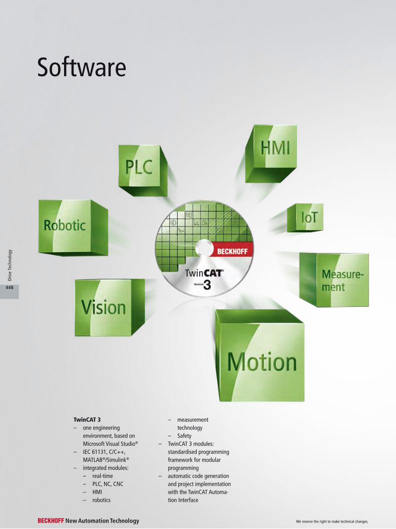
TwinCAT 3– one engineering
environment, based on Microsoft Visual Studio®
– IEC 61131, C/C++, MATLAB®/Simulink®
– integrated modules:– real-time– PLC, NC, CNC– HMI– robotics
Software
– measurement technology
– Safety– TwinCAT 3 modules:
standardised programming framework for modular programming
– automatic code generation and project implementation with the TwinCAT Automa-tion Interface
We reserve the right to make technical changes.
448
Driv
e Te
chno
logy
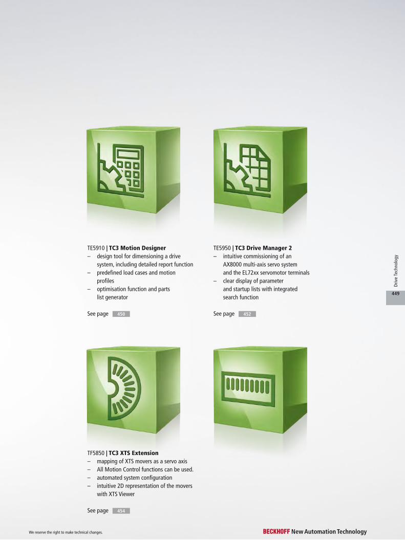
TF5850 | TC3 XTS Extension– mapping of XTS movers as a servo axis– All Motion Control functions can be used.– automated system configuration– intuitive 2D representation of the movers
with XTS Viewer
See page 454
TE5910 | TC3 Motion Designer– design tool for dimensioning a drive
system, including detailed report function– predefined load cases and motion
profiles– optimisation function and parts
list generator
TE5950 | TC3 Drive Manager 2– intuitive commissioning of an
AX8000 multi-axis servo system and the EL72xx servomotor terminals
– clear display of parameter and startup lists with integrated search function
See page 450 See page 452
We reserve the right to make technical changes.
449
Driv
e Te
chno
logy

TE5910
TE5910 | TC3 Motion DesignerThe dimensioning of drive axes, in conjunction with the optimum selection of motor, gear unit, drive controllers and accesso-ries, is the basis for an efficient machine design. The TC3 Motion Designer is optionally integrated in the TwinCAT automation platform, or it can be used as a stand-alone project engineer-ing tool for mechanical design.
MechanicsThe TC3 Motion Designer sup-ports the designer in the configu-ration of typical mechanical sys-tems such as pinion rack, spindle nut, winder, crank drive, etc.
Motion profilesRough estimates for simple load cases with motion profiles, e.g. based on a 1/2 or 1/3 rule or a 7-segment profile, are easy to realise with a few mouse clicks. More complex tasks and kine-
matic systems, perhaps in con-junction with more sophisticated motion profiles, including cam gears according to VDI 2143, are also taken account of in the TC3 Motion Designer. Export functions enable the configura-tion to be transferred directly to the TwinCAT System Manager, without the need for repeated inputs.
Optimisation functionAn optimisation algorithm makes the selection of gear units and motors straightforward. It sug-gests the optimum combina- tion based on mechanical and cost considerations, taking into account adjustable filters. The connected database pro-vides access to all available gear units, motors and servo drives offered by Beckhoff, including the compact Drive Technology range with servo terminals.
The automatic geometry match-ing feature checks the compat-ibility of motor and gear unit and prevents selection of unsuitable combinations.
Report functionsThe axis configuration is docu-mented in a report. A choice of short or detailed report is avail-able.
With a single click the designer can call up the techni-cal data sheet for the motor and gear unit, and with a further click the corresponding 3D model of the drive components for inte-gration in the design software.
Parts list generatorThe integrated parts list gener-ator can be used directly for preparing the purchase order. Accessories such as cables, chokes and installation material are also considered.
Multi-axis designThe TC3 Motion Designer regards the machine as a holistic unit, including all drive axes: All load cycles, including their temporal dependence and their influence on the common DC-Link, are taken into account. Selection of the optimum supply module or the common brake resistor is guaranteed.
We reserve the right to make technical changes.
450
Driv
e Te
chno
logy
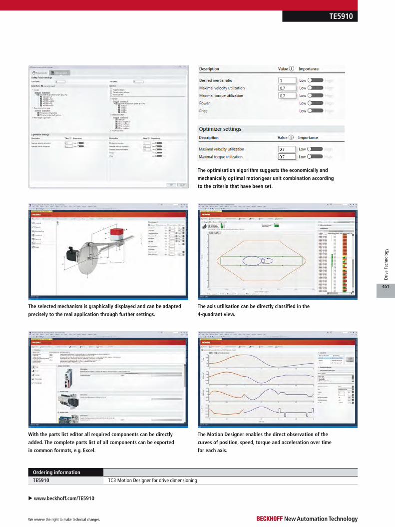
TE5910
The optimisation algorithm suggests the economically and
mechanically optimal motor/gear unit combination according
to the criteria that have been set.
u www.beckhoff.com/TE5910
The selected mechanism is graphically displayed and can be adapted
precisely to the real application through further settings.
The axis utilisation can be directly classified in the
4-quadrant view.
The Motion Designer enables the direct observation of the
curves of position, speed, torque and acceleration over time
for each axis.
With the parts list editor all required components can be directly
added. The complete parts list of all components can be exported
in common formats, e.g. Excel.
Ordering information
TE5910 TC3 Motion Designer for drive dimensioning
We reserve the right to make technical changes.
451
Driv
e Te
chno
logy

The TC3 Drive Manager 2 is used for commissioning the AX8000 or the EL72xx, EP72xx and EJ72xx I/O components. It is optionally available as an integrated version in the TwinCAT automation plat- form or an update version independently of TwinCAT. The TC3 Drive Manager 2 is integrated into a TwinCAT solution as a project and enables a separate assess- ment of supply modules, axis modules and axis channels.
Automatic startup listThe menu structure enables intuitive axis commissioning. Via the electronic identification plate, TC3 Drive Manager 2 automatically identifies the motor and corresponding parameter data. As a result, a startup list is automatically generated for each axis.
Scope View is integratedUsing the Run Motor function, the motor is ready for opera- tion with an NC control system.
The combination of NC control with the Scope View tool pro-vides an optimal overview of the motor in operation. A fine-tuning of the axis and a minimisation of the tracking error is easy and straightforward.
Further adaptations are pos-sible directly in the TC3 Drive Manager 2 via the Tune Drive function, such as the adjustment of parameter settings and the configuration of filters.
TE5950 | TC3 Drive Manager 2
TE5950
We reserve the right to make technical changes.
452
Driv
e Te
chno
logy

u www.beckhoff.com/TE5950
TE5950
Ordering information
TE5950 TC3 Drive Manager 2
Detailed visualisation of the motor characteristic according to the
electronic identification plate
Structured parameter list with integrated search function
All diagnostic messages at a glance and an additional watch window
with individual user options
Direct fine-tuning of the drive during commissioning
Integrated scope in the NC control overview of the motor
We reserve the right to make technical changes.
453
Driv
e Te
chno
logy
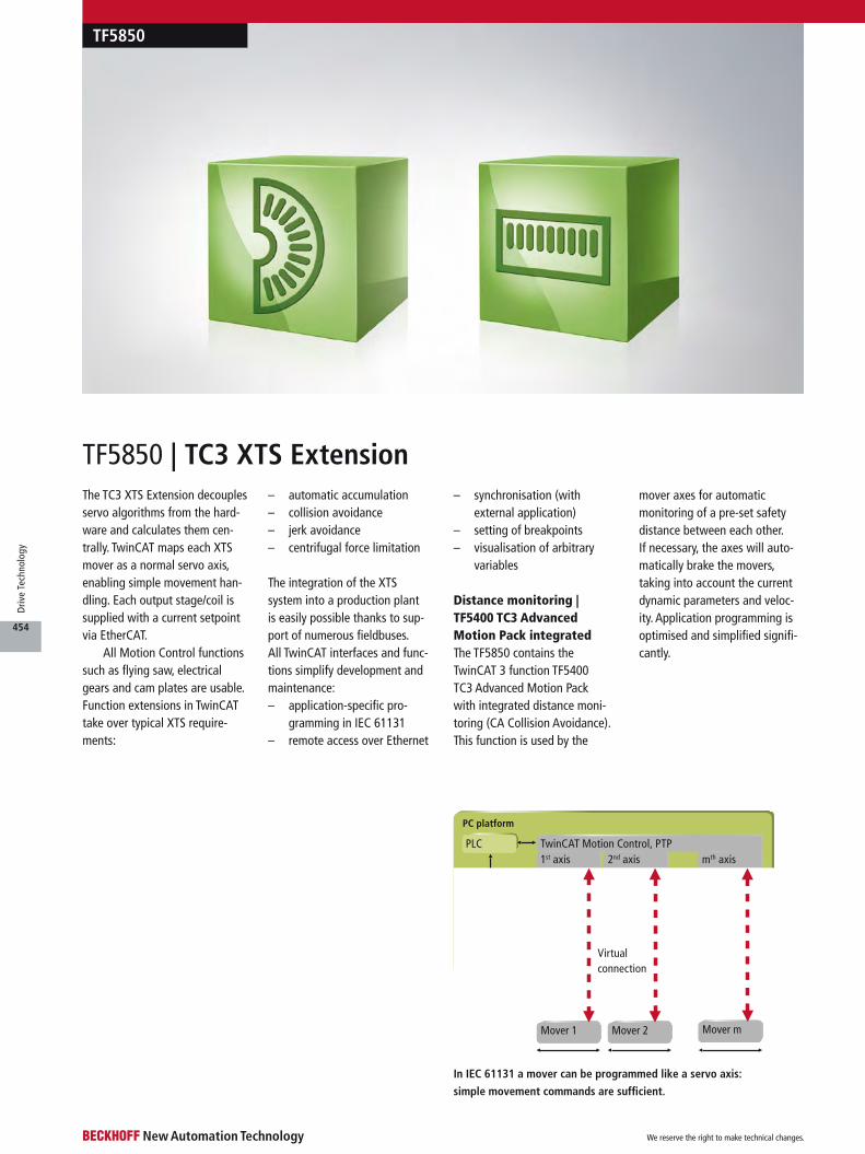
The TC3 XTS Extension decouples servo algorithms from the hard-ware and calculates them cen-trally. TwinCAT maps each XTS mover as a normal servo axis, enabling simple movement han-dling. Each output stage/coil is supplied with a current setpoint via EtherCAT.
All Motion Control functions such as flying saw, electrical gears and cam plates are usable. Function extensions in TwinCAT take over typical XTS require-ments:
– automatic accumulation– collision avoidance– jerk avoidance– centrifugal force limitation
The integration of the XTS system into a production plant is easily possible thanks to sup-port of numerous fieldbuses. All TwinCAT interfaces and func-tions simplify development and maintenance:– application-specific pro-
gramming in IEC 61131– remote access over Ethernet
– synchronisation (with external application)
– setting of breakpoints– visualisation of arbitrary
variables
Distance monitoring | TF5400 TC3 Advanced Motion Pack integratedThe TF5850 contains the TwinCAT 3 function TF5400 TC3 Advanced Motion Pack with integrated distance moni-toring (CA Collision Avoidance). This function is used by the
mover axes for automatic monitoring of a pre-set safety distance between each other. If necessary, the axes will auto-matically brake the movers, taking into account the current dynamic parameters and veloc-ity. Application programming is optimised and simplified signifi-cantly.
TF5850
Power output stages
PLC
EtherCAT master
EtherCAT, XFC
PC platform
TwinCAT Motion Control, PTP
Dynamic data distribution
1st axis
SoftDrive
2nd axis
SoftDrive
mth axis
SoftDrive
Mover 1 Mover 2 Mover m
Virtual connection
In IEC 61131 a mover can be programmed like a servo axis:
simple movement commands are sufficient.
TF5850 | TC3 XTS Extension
We reserve the right to make technical changes.
454
Driv
e Te
chno
logy

u www.beckhoff.com/TwinCAT3
TF5850
TC3 XTS Extension | In application programming, a mover is handled like a conventional servo axis.
Application software
Customer application
NC functions
XTS Extension
Ordering information
TF5850-0050 software license, TwinCAT 3 XTS Extension, TwinCAT 3 platform P50 (performance plus)
TF5850-0060 software license, TwinCAT 3 XTS Extension, TwinCAT 3 platform P60 (mid performance)
TF5850-0070 software license, TwinCAT 3 XTS Extension, TwinCAT 3 platform P70 (high performance)
TF5850-0080 software license, TwinCAT 3 XTS Extension, TwinCAT 3 platform P80 (very high performance)
TF5850-0081 software license, TwinCAT 3 XTS Extension, TwinCAT 3 platform P81 (Many Core, 5-8 Cores)
TF5850-0082 software license, TwinCAT 3 XTS Extension, TwinCAT 3 platform P82 (Many Core, 9-16 Cores)
TF5850-0083 software license, TwinCAT 3 XTS Extension, TwinCAT 3 platform P83 (Many Core, 17-32 Cores)
TF5850-0084 software license, TwinCAT 3 XTS Extension, TwinCAT 3 platform P84 (Many Core, 33-64 Cores)
The XTS configurator enables largely automated system
configuration.
Axis and controller parameters of a mover can simply be copied
within the XTS configurator.
The XTS viewer renders an intuitive online 2D represenation of the
movers in motion and can be used as a diagnostics and simulation tool.
We reserve the right to make technical changes.
455
Driv
e Te
chno
logy