MOSSY CREEK DAM REMOVAL AND RESTORATION, AUGUSTA COUNTY
27
MOSSY CREEK DAM REMOVAL AND RESTORATION, AUGUSTA COUNTY, VIRGINIA: PROJECT SUMMARY AND DESIGN REPORT By: John B. Hutzell and Richard R. Starr Stream Habitat Assessment and Restoration Program U.S. Fish and Wildlife Service Chesapeake Bay Field Office CBFO – S12 - 02 Annapolis, MD January 2012
Transcript of MOSSY CREEK DAM REMOVAL AND RESTORATION, AUGUSTA COUNTY

MOSSY CREEK DAM REMOVAL AND RESTORATION, AUGUSTA COUNTY, VIRGINIA: PROJECT SUMMARY AND DESIGN REPORT
By: John B. Hutzell and Richard R. Starr
Stream Habitat Assessment and Restoration Program U.S. Fish and Wildlife Service Chesapeake Bay Field Office CBFO – S12 - 02
Annapolis, MD January 2012

Mossy Creek Dam Removal and Stream Restoration: Project Summary and Design Report
TABLE OF CONTENTS
I. INTRODUCTION.................................................................................................................1
II. WATERSHED AND GEOMORPHIC ASSESSMENT ....................................................1 A. Watershed Assessment ......................................................................................................2 B. Basemapping .....................................................................................................................5 C. Project Reach Geomorphic Assessment ...........................................................................5 D. Bankfull Verification ........................................................................................................7
III. PRELIMINARY DESIGN ...................................................................................................9
A. Goals and Restoration Potential ........................................................................................9 B. Design Criteria ...............................................................................................................10 C. Conceptual Design .........................................................................................................11
IV. FINAL DESIGN ..................................................................................................................11
A. Natural Channel Design ..................................................................................................11 B. Sediment Transport .........................................................................................................11 C. In-Stream Structures .......................................................................................................12 D. Vegetation Design ...........................................................................................................13
V. MAINTENANCE AND MONITORING PLANS............................................................13
A. Maintenance Plan ............................................................................................................13 B. Monitoring Plan ..............................................................................................................13
VI. LITERATURE CITED ......................................................................................................15
U. S. Fish and Wildlife Service January 2012 Chesapeake Bay Field Office P a g e | i

Mossy Creek Dam Removal and Stream Restoration: Project Summary and Design Report
U. S. Fish and Wildlife Service January 2012 Chesapeake Bay Field Office P a g e | ii
LIST OF FIGURES Figure 1. Site Location .......................................................................................................................4 Figure 2. Photo – Bypass Channel .....................................................................................................5 Figure 3. Photo – Upstream Conditions .............................................................................................6 Figure 4. Photo – Downstream Conditions ........................................................................................7 Figure 5. Typical Bankfull Indicators ................................................................................................8 Figure 6. Cross Vane in Plan View ....................................................................................................12
LIST OF TABLES
Table 1. Mossy Creek and Regional Curve Bankfull Characteristics ...............................................8 Table 2. Mossy Creek Phase 1 – Goals and Objectives .....................................................................9 Table 3. Mossy Creek Design Criteria ...............................................................................................10
APPENDICES
Appendix A. Mossy Creek Phase 1 – 100% Design – Existing Conditions Appendix B. Mossy Creek Phase 1 – 100% Design – Proposed Conditions Appendix C. Mossy Creek – Natural Channel Design Checklist

Mossy Creek Dam Removal and Stream Restoration: Project Summary and Design Report
U. S. Fish and Wildlife Service January 2012 Chesapeake Bay Field Office P a g e | 1
I. INTRODUCTION Trout Unlimited (TU), the U.S. Fish and Wildlife Service (Service) - Chesapeake Bay Field Office and the Virginia Department of Game and Inland Fish (VDGIF) are involved in a collaborative effort to restore in stream habitat and re-establish Brook trout in two miles of Mossy Creek, located in Augusta County, Virginia. This large scale effort is being implemented in two phases. The first phase is to remove a dam and restore 300 linear feet of stream. The second phase is to restore 2,200 linear feet of stream. This report will outline Phase 1 of the proposed restoration. Mossy Creek is located in the Chesapeake Bay watershed of Virginia flowing north 6.5 miles from its spring source in Augusta County into North River, which flows into the South Fork of the Shenandoah River and ultimately enters the Chesapeake Bay near Washington DC. Mossy Creek has been one of the premier trout streams of Virginia due mostly to the fact that as much as 80% of its base flow is derived from cold-water springs providing the water temperature necessary for trout survival. It is a classic meadow limestone stream and Virginia’s best-known spring fed creek.
This project will draw on the experience and expertise of federal and state agencies, non-governmental organizations and local volunteers to design, construct, monitor and maintain the restored area. The goal of the restoration is to remove a dam on Mossy Creek that is located downstream of the Route 809 Bridge and restore 2500 linear feet of stream both upstream and downstream of the Route 809 Bridge. The dam was constructed across the stream valley and consists of a poured concrete headwall that is approximately 200 feet long, 5 feet wide at the base, and 9 feet high. The dam has been partially breached but still constricts and alters water levels and fish passage. The restoration will involve the removal of the dam and returning the stream channel in the vicinity to a stable, self-maintaining state. This will significantly increase the amount of available aquatic habitat and help promote a sustainable brook trout population as well as other resident fish and aquatic species.
The purpose of this report is to present the findings of a watershed and stream assessment and explain the methodology and procedures used in the development of a restoration design. Specifically, this report contains the methodologies used by the Service and follows criteria outlined in the Natural Channel Design Checklist (Harman & Starr. 2011); a brief watershed characterization; a brief stream characterization and stability condition description; the results of the stream assessment; and stream restoration design. II. WATERSHED AND GEOMORPHIC ASSESSMENT This section presents a brief summary of the methods used by the Service to conduct a limited watershed and stream assessment, develop restoration objectives, and develop a restoration design.
Mossy Creek Dam Removal and Stream Restoration: Project Summary and Design Report
U. S. Fish and Wildlife Service January 2012 Chesapeake Bay Field Office P a g e | 2
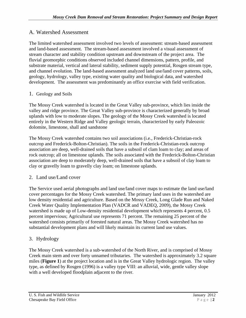
A. Watershed Assessment The limited watershed assessment involved two levels of assessment: stream-based assessment and land-based assessment. The stream-based assessment involved a visual assessment of stream character and stability condition upstream and downstream of the project area. The fluvial geomorphic conditions observed included channel dimensions, pattern, profile, and substrate material, vertical and lateral stability, sediment supply potential, Rosgen stream type, and channel evolution. The land-based assessment analyzed land use/land cover patterns, soils, geology, hydrology, valley type, existing water quality and biological data, and watershed development. The assessment was predominantly an office exercise with field verification. 1. Geology and Soils The Mossy Creek watershed is located in the Great Valley sub-province, which lies inside the valley and ridge province. The Great Valley sub-province is characterized generally by broad uplands with low to moderate slopes. The geology of the Mossy Creek watershed is located entirely in the Western Ridge and Valley geologic terrain, characterized by early Paleozoic dolomite, limestone, shall and sandstone The Mossy Creek watershed contains two soil associations (i.e., Frederick-Christian-rock outcrop and Frederick-Bolton-Christian). The soils in the Frederick-Christian-rock outcrop association are deep, well-drained soils that have a subsoil of clam loam to clay; and areas of rock outcrop; all on limestone uplands. The soils associated with the Frederick-Bolton-Christian association are deep to moderately deep, well-drained soils that have a subsoil of clay loam to clay or gravelly loam to gravelly clay loam; on limestone uplands. 2. Land use/Land cover The Service used aerial photographs and land use/land cover maps to estimate the land use/land cover percentages for the Mossy Creek watershed. The primary land uses in the watershed are low density residential and agriculture. Based on the Mossy Creek, Long Glade Run and Naked Creek Water Quality Implementation Plan (VADCR and VADEQ, 2009), the Mossy Creek watershed is made up of Low-density residential development which represents 4 percent, 0.5 percent impervious; Agricultural use represents 71 percent. The remaining 25 percent of the watershed consists primarily of forested natural areas. The Mossy Creek watershed has no substantial development plans and will likely maintain its current land use values. 3. Hydrology The Mossy Creek watershed is a sub-watershed of the North River, and is comprised of Mossy Creek main stem and over forty unnamed tributaries. The watershed is approximately 3.2 square miles (Figure 1) at the project location and is in the Great Valley hydrologic region. The valley type, as defined by Rosgen (1996) is a valley type VIII: an alluvial, wide, gentle valley slope with a well developed floodplain adjacent to the river.

Mossy Creek Dam Removal and Stream Restoration: Project Summary and Design Report
U. S. Fish and Wildlife Service January 2012 Chesapeake Bay Field Office P a g e | 3
Mossy Creek exhibits a flow regime typical of streams found in rural areas. Most runoff is absorbed into the soils, recharging the water table. Since Mossy Creek is predominantly spring fed, and there is little impervious surface, Mossy Creek does not exhibit “flashy” flows commonly found in urban settings. The Service did not conduct any hydrology calculations due to the low complexity design and the relatively low influence that the hydrology will have on the design. 4. Hydraulic Assessment The Service did not conduct a hydraulic assessment of this particular reach due to the low complexity of the restoration design. The design used the existing channel and floodplain dimensions upstream and downstream of the reach and these conditions are stable. Therefore, velocities, shear stress, and stream power in relation to stage and discharge would not change because of the restoration design. 5. Riparian Vegetation The project area exists within a natural forested setting of mature hardwoods with a dense canopy and little understory. The buffer width ranges from approximately 10 to 100 feet, consisting of native and non-native grasses, shrubs, understory trees, and mature canopy trees.

Mossy Creek Dam Removal and Stream Restoration: Project Summary and Design Report
U. S. Fish and Wildlife Service January 2012 Chesapeake Bay Field Office P a g e | 4
Figure 1. Site Location

Mossy Creek Dam Removal and Stream Restoration: Project Summary and Design Report
U. S. Fish and Wildlife Service January 2012 Chesapeake Bay Field Office P a g e | 5
B. Base Mapping
The Service received 1-foot ground survey information to accurately map (Appendix A) and represent the project area. This Service used this information to assess base line conditions and to develop a restoration design plan. Plan form, longitudinal profile, and topographic information is represented.
C. Project Reach Geomorphic Assessment The Service conducted a visual Rosgen Level II assessment to assess the portion of Mossy Creek adjacent to the derelict dam. The Rosgen Level II assessment describes the existing morphological character of the stream and classifies the stream using the Rosgen stream classification system (Rosgen 1994). The Rosgen stream classification system uses physical features of a stream such as width, depth, pattern, and bed material, to group streams into a “type” denoted by alphanumeric codes. The Service found that the Mossy creek had bypassed the dam (Figure 2) during a high flow event in the past, and has now formed a separate channel that flows around the left side of the dam. A small portion of flow continues to move through the outlet structure of the dam, but the majority of the water is being conveyed through the bypass channel (Appendix A).
Figure 2. Bypass channel

Mossy Creek Dam Removal and Stream Restoration: Project Summary and Design Report
U. S. Fish and Wildlife Service January 2012 Chesapeake Bay Field Office P a g e | 6
The bypass channel shows signs of widespread vertical and lateral instability. This instability is indicative of a stream that is still undergoing adjustment, which is typical of a newly formed channel or avulsion. However, this bypass channel is unlikely to stabilize due to its location and lateral constraints. The channel cut through unconsolidated deposition and fill material so the majority of the banks are unstable and highly erodible. The channel is actively incising, as there does not seem to be any stable grade control. The access to available floodplain is also limited due to the steep side slope on the left bank, and the intact dam on the right bank. With these constraints, it is expected that channel incision will continue to move upstream with little hope of stabilization and this reach will continue to be a large source of sediment to Mossy Creek. The areas directly upstream (Figure 3) and downstream (Figure 4) of the dam (excluding the bypass channel) show indices of a stable Rosgen C4 channel with well-defined characteristics and minimal instability. The width-to-depth ratio and entrenchment ratio are within acceptable ranges for a Rosgen C channel and particle distributions are consistent with the Rosgen C4 channel type as well. Channel stability could be compromised if the baypass channel continues to erode, however if measures are taken to remove the bypass channel, it is expected that the channel will remain stable. Any further assessment was unnecessary due to the limited complexity of the restoration design and limited extent of the proposed restoration project area.
Figure 3. Upstream conditions

Mossy Creek Dam Removal and Stream Restoration: Project Summary and Design Report
U. S. Fish and Wildlife Service January 2012 Chesapeake Bay Field Office P a g e | 7
Figure 4. Downstream conditions
D. Bankfull Verification Bankfull discharge characterizes the range of discharges that is effective in shaping and maintaining a stream. Over time, geomorphic processes adjust the stream capacity and shape to accommodate the bankfull discharge within the stream. Bankfull discharge is strongly correlated to many important stream morphological features (e.g., bankfull width, drainage area, etc.) and is the critical parameter used by the Service in assessing Mossy Creek. Bankfull discharge is also used in natural channel design procedures as a scale factor to convert morphological parameters from a stable reach of one size to a disturbed reach of another size. During the Mossy Creek assessment, the Service identified bankfull stage using physical indicators of bankfull stage described by McCandless and Everett (2002). Figure 5 depicts significant geomorphic indicators typically found in the Mid-Atlantic Region. Based on these indicators, the Service identified a consistent geomorphic feature at Mossy Creek. This geomorphic indicator was typically a significant slope break associated with the floodplain that was found throughout the project area. The floodplains were well developed in this area and were typically the highest geomorphic feature adjacent to the stream.

Mossy Creek Dam Removal and Stream Restoration: Project Summary and Design Report
U. S. Fish and Wildlife Service January 2012 Chesapeake Bay Field Office P a g e | 8
The Service compared representative cross section dimension to the regional relationships of the same parameters developed for the Maryland Appalachian Plateau / Valley and Ridge (McCandless and Everett 2002) physiographic regions for verification (Table 1). The representative cross section dimensions were collected approximately 400 feet downstream of the projects area. The representative cross section dimensions were higher than the Maryland Appalachian Plateau / Valley and Ridge data due to the fact that Mossy Creek is charged more so by its strong spring source than run-off. Therefore, the Service determined that the existing condition measurements, since the floodplain was so well developed, were more favorable to develop design criteria.
The Service compared representative cross section dimension to the regional relationships of the same parameters developed for the Maryland Appalachian Plateau / Valley and Ridge (McCandless and Everett 2002) physiographic regions for verification (Table 1). The representative cross section dimensions were collected approximately 400 feet downstream of the projects area. The representative cross section dimensions were higher than the Maryland Appalachian Plateau / Valley and Ridge data due to the fact that Mossy Creek is charged more so by its strong spring source than run-off. Therefore, the Service determined that the existing condition measurements, since the floodplain was so well developed, were more favorable to develop design criteria.
Bankfull Characteristics
Reach 1 Representative Cross Section
Reach 2 Representative Cross Section
Maryland AP/VR Regional Curve
Area (ft2) 53.39 60.27 31.50Width (ft) 34.05 30.43 22.00Depth (ft) 1.57 1.98 1.40Discharge (cfs) 279.23 368.85 108.90
Table 1. Mossy Creek and Regional Curve Bankfull Characteristics
1. Maryland Stream Survey: Bankfull Discharge and Channel Characteristics of Streams in the AP/VR Hydrologic Region (McCandless and Everett 2002)
Figure 5: Typical Bankfull Indicators (McCandless and Everett 2002)

Mossy Creek Dam Removal and Stream Restoration: Project Summary and Design Report
U. S. Fish and Wildlife Service January 2012 Chesapeake Bay Field Office P a g e | 9
III. PRELIMINARY DESIGN This section presents the project goals, design criteria, and conceptual design parameters involved in the Mossy Creek Dam Removal and Restoration. A. Restoration Goals and Objectives The Service generated objectives based on Service and Trout Unlimited missions. These goals focused on improving stream function by developing quantifiable objectives. This goal setting method follows guidelines developed by the Service in the Stream Function Framework Pyramid document. Goal setting is critical to the success of a project because it communicates why the project is being done and sets expectations on how success will be measured (Harman, et al. 2011). These goals and objectives are focused on level’s 2 & 3 of the pyramid. They were then discussed and combined into one list and include the following: Table 2. Mossy Creek Phase 1 - Goals and Objectives. The underlined words under the objectives are parameters or measurement methods from the Stream Functions Pyramid (Harman, et al. 2011) Goals ObjectivesProvide fish passage for Brook Trout 1. Demolish derelict mill dam
Reduce sediment supply from eroding streambanks
1. Reduce stream bank erosion rates to match upstream and downstream erosion rates (bank migration / lateral stability).
2. Eliminate erosion associated with bypass channel by filling bypass channel and planting riparian vegetation.
3. Plant riparian vegetation to match species diversity and composition of upstream and downstream conditions. 4. Provide bank stability, cover, and runoff filtration by planting a dense riparian buffer of native plants to achieve 80% canopy cover.
Mossy Creek Dam Removal and Stream Restoration: Project Summary and Design Report
U. S. Fish and Wildlife Service January 2012 Chesapeake Bay Field Office P a g e | 10
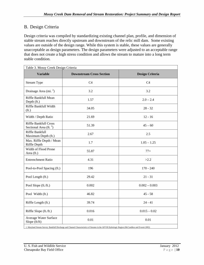
B. Design Criteria
Design criteria was compiled by standardizing existing channel plan, profile, and dimension of stable stream reaches directly upstream and downstream of the relic mill dam. Some existing values are outside of the design range. While this system is stable, these values are generally unacceptable as design parameters. The design parameters were adjusted to an acceptable range that does not create a high stress condition and allows the stream to mature into a long term stable condition.
Table 3. Mossy Creek Design Criteria
Variable Downstream Cross Section Design Criteria
Stream Type C4 C4
Drainage Area (mi. 2) 3.2 3.2
Riffle Bankfull Mean Depth (ft.) 1.57 2.0 – 2.4
Riffle Bankfull Width (ft.) 34.05 28 - 32
Width / Depth Ratio 21.69 12 - 16
Riffle Bankfull Cross Sectional Area (ft. 2) 51.39 45 – 60
Riffle Bankfull Maximum Depth (ft.) 2.67 2.5
Max. Riffle Depth / Mean Riffle Depth 1.7 1.05 – 1.25
Width of Flood Prone Area (ft.) 55.87 77+
Entrenchment Ratio 4.31 >2.2
Pool-to-Pool Spacing (ft.) 196 170 - 240
Pool Length (ft.) 29.42 21 - 31
Pool Slope (ft./ft.) 0.002 0.002 – 0.003
Pool Width (ft.) 46.82 45 - 58
Riffle Length (ft.) 39.74 24 - 41
Riffle Slope (ft./ft.) 0.016 0.015 – 0.02
Average Water Surface Slope (ft/ft) 0.01 0.01
1. Maryland Stream Survey: Bankfull Discharge and Channel Characteristics of Streams in the AP/VR Hydrologic Region (McCandless and Everett 2002)

Mossy Creek Dam Removal and Stream Restoration: Project Summary and Design Report
U. S. Fish and Wildlife Service January 2012 Chesapeake Bay Field Office P a g e | 11
C. Conceptual Design
A conceptual design was completed and submitted to project partners prior to the creation of this document. This document focuses on the final restoration design criteria and plans.
IV. FINAL DESIGN A. Natural Channel Design
The Service developed stream restoration designs based on the restoration objectives and the stability problems identified during the watershed and stream assessment. The Service only considered restoration practices based on natural channel design (NCD) principles. The Natural Channel Design methodology incorporates a combination of analog, empirical, and analytical methods for assessment and design. Because all rivers within a wide range of valley types do not exhibit similar morphological, sedimentological, hydraulic, or biological characteristics, it is necessary to group rivers of similar characteristics into discreet stream types. Such characteristics are obtained from stable reference reach locations by discreet valley types, and then are converted to dimensionless ratios for extrapolation to disturbed stream reaches of various sizes. (USDA 2007) The results of the watershed and stream assessment showed that both the upstream and downstream portions of Mossy Creek directly adjacent to the dam are stable. Currently, the dam is providing grade control and the removal of the dam will increase the likelihood of a headcut developing in the system. A headcut could form due to the streambed elevation difference upstream and downstream of the dam. With the dam removed, facet slopes would increase to unstable levels causing the bed to effectively downcut and begin to migrate upstream. The Service intends to return the channel back to its original path, and abandon and fill the unstable bypass channel that has formed, leaving the lower third intact to provide additional vernal habitat. Therefore, the restoration design (Appendix B) includes the removal of the dam and the installation of a grade control structure and channel dimension and profile modifications just upstream of the dams location. These modifications will reflect the stable upstream and downstream conditions and maintain floodplain connectivity in the system as well as provide grade control to eliminate the possibility of any incision or headcut potential following construction. B. Sediment Transport
The Service did not conduct a sediment transport study of this particular reach due to the low complexity of the restoration design and limited extent of the project area. The design used the existing channel and floodplain dimensions upstream and downstream of the reach and these conditions are stable. Therefore, competence and capacities will not change as a result of the restoration design.

Mossy Creek Dam Removal and Stream Restoration: Project Summary and Design Report
U. S. Fish and Wildlife Service January 2012 Chesapeake Bay Field Office P a g e | 12
C. In-Stream Structures
Rock and log structures are instream structures, made of rocks or a combination of rocks and logs, that provide both lateral and vertical channel stability. They were developed by Wildland Hydrology, Inc. (2001) to reduce shear stress along the outer banks of meander curves and halt vertical degradation, but may be used also to steer and redirect the direction of flow through bends. The Service has determined that a single Rock Cross-Vane with step will be most suited to address any concern of instability post dam removal. The location of this structure was determined by matching natural pool-to-pool spacing characteristics of the system. The structure was also strategically placed to provide protection to existing cultural resources. 1. Cross-Vane
The Cross-Vane (Figure 6) will establish grade control, reduce bank erosion, create a stable width/depth ratio, maintain channel capacity, while maintaining sediment transport capacity, and sediment competence. The Cross-Vane also provides for the proper natural conditions of secondary circulation patterns commensurate with channel pattern, but with high velocity gradients and boundary stress shifted from the near-bank region. The Cross-Vane is also a stream habitat improvement structure due to: 1) an increase in bank cover as a result to a differential raise of the ater surface in the bank region; 2) the creation of holding and refuge cover during both high and low flow periods in the deep pool; 3) the development of feeding lanes in the flow separation zones (the interface between fast and slow water) due to the strong down welling and upwelling forces in the center of the channel; and 4) the creation of spawning habitat in the tail-out or glide portion of the pool. (Rosgen, 2010)
Figure 6. Cross-Vane in Plan View
Mossy Creek Dam Removal and Stream Restoration: Project Summary and Design Report
U. S. Fish and Wildlife Service January 2012 Chesapeake Bay Field Office P a g e | 13
D. Vegetation Design
The riparian buffer is an integral part of the stream ecosystem, providing bank stability and nutrient uptake, serving as a food source for aquatic organisms, and providing terrestrial habitat and migration corridors for various types of wildlife, including migratory neotropical songbirds. Shading from the buffer moderates stream temperature and prevents excessive algal growth. Large woody debris derived from the buffer is an important component of aquatic habitat. The Service developed stream restoration planting plan that utilizes native plant and shrub species in both the riparian and upland corridors. The only areas that will be targeted for post-construction planting will be those areas that are disturbed during the implementation process. The species selected are consistent with native species found in the central Virginia area. V. MAINTENANCE AND MONITORING PLANS
A. Maintenance Plan
The Service will collaborate with Trout Unlimited to develop a maintenance plan that will ensure the success of the restoration objectives and goals. Plan duration and responsible parties will also be determined at that time.
B. Monitoring Plan
The Service will produce an As-Built survey directly following completion of the restoration. This survey will be used to confirm that the project was built to design standards and will serve as baseline data for future monitoring. The Service will compare this data to the design criteria and produce a brief report summarizing any implementation adjustments or discrepancies. A well-developed post-restoration monitoring plan will allow the partners to determine the success of the project, and address any problems that may arise. The Service, VDGIF and TU have developed a monitoring plan based on the restoration goals and objectives outlined in section 3A, to evaluate the performance of the stream restoration project. This will take place after the successful completion of both phase 1 & 2 of the Mossy Creek Restoration. A Rapid Monitoring Protocol (RMP), developed by the Service-CBFO, will be used to monitor the physical characteristics of the restoration projects. The RMP is a tiered approach for rapid restoration assessment that visually evaluates the stability and qualitative functional success of the restoration project. If there are indications of potential failure, the methodology requires that the project evaluators conduct a more intensive monitoring survey, which is the second tier survey. However, if a severe problem is identified (e.g. complete structure failure, excessive bank erosion, vertical incision > 1.3) the second tier may be skipped to go directly to the third tier if remediation or repair is required. During the second tier survey, project evaluators take measurements of the existing stream conditions and compare them to the proposed design criteria and reference data, to determine if remediation is required. If repair is required, the evaluators will perform a third tier survey that includes restoration design and implementation.

Mossy Creek Dam Removal and Stream Restoration: Project Summary and Design Report
U. S. Fish and Wildlife Service January 2012 Chesapeake Bay Field Office P a g e | 14
The success of the riparian buffer plantings will also be monitored by visually quantifying bare areas, invasive species distribution, native recruitment and survivability of planted species. The Service will monitor the stream for three years and provide a brief monitoring summary report for each year of monitoring. Biological monitoring will be carried out when Brook Trout are reintroduced into the watershed.

Mossy Creek Dam Removal and Stream Restoration: Project Summary and Design Report
U. S. Fish and Wildlife Service January 2012 Chesapeake Bay Field Office P a g e | 15
VI. LITERATURE CITED
1. Harman, W., R. Starr. 2011. Natural Channel Design Review Checklist. US Fish and Wildlife Service, Chesapeake Bay Field Office, Annapolis, MD.
2. Harman, W., R. Starr, M. Carter, K. Tweedy, M. Clemmons, K. Suggs, C. Miller. 2011. A Function-Based Framework for Developing Stream Assessments, Restoration Goals, Performance Standards and Standard Operating Procedures. U.S. Environmental Protection Agency, Office of Wetlands, Oceans, and Watersheds. Washington, D.C.
3. Limerinos, J.T. 1970. Determination of Manning’s Coefficient from Measured Bed Roughness in Natural Channels. U.S. Geological Survey Water Supply Paper 1898-B, Prepared in cooperation with the California Department of Water Resources, U.S. Government Printing Office, Washington, DC.
4. Leopold, L.B., M.G. Wolman, and J. Miller, 1964. Fluvial Processes in Geomorphology, W.H. Freeman Company. San Francisco, CA.
5. Leopold, L. B. 1994. A View of the River. Harvard University Press, Cambridge, MA.
6. Marshall, Tyler, Rausch, LLC. 1999. U.S. National Arboretum: Storm water management conceptual design for Hickey Run sub-watershed.
7. McCandless, T.L., R.A. Everett. 2002. Maryland stream survey: Bankfull discharge and channel characteristics in the Piedmont hydrologic region. CBFO-S02-02. U.S. Fish and Wildlife Service, Annapolis, MD.
8. Rosgen, D.R. 1996. Applied River Morphology. Wildland Hydrology. Pagosa Springs, CO.
9. Rosgen, D.R. 2010. The Cross-Vane, W-Weir and J-Hook Vane Structures… Their Description, Design and Application for Stream Stabilization and River Restoration. Wildland Hydrology. Pagosa Springs, CO.
10. USDA. 2007. Part 654 Stream Restoration Design National Engineering Handbook. pp. 11-1
11. VADCR and VADEQ. 2009. Mossy Creek, Long Glade Run and Naked Creek Watershed Improvement Plan.
12. “A Stream Channel Stability Assessment Methodology”. Proceedings of the Seventh Federal Interagency Sedimentation Conference, Vol. 2, pp. II – 9-15, March 18 - 26, 2001, Reno, NV.

APPENDIX A


APPENDIX B


APPENDIX C

Natural Channel Design Review Checklist
Project Design Checklist Reviewer:Date:
Project: Mossy Creek Dam Removal - Phase 1Engineer: Ben Hutzell
Submitted(Y/N)
Acceptable(Y/N)
Page #
Yes 2
Yes 2
Yes 2
Yes 2
No
Yes Appendix A
No 3
No 3
Yes 7
1.1 Watershed Assessment1.0 Watershed and Geomorphic Assessment
1.1c Was the percent impervious cover for the watershed provided?
Comments
1.1a Was the watershed assessment methodology described?
1.1d Was the current land use described along with future conditions?1.1e Were watershed hydrology calculations performed?
Item
1.2a Does the project include basemapping?
1.2 Basemapping
1.1b Was the project drainage area provided?
1.4a Were bankfull verification analyses completed?
1.3 Hydraulic Assessment
1.3a Was a hydraulic assessment completed?Ther Service did not complete a hydraulic assessment of this particular reach due to the low complexity of the restoration design.
1.3b Was stream velocity, shear stress and stream power shown in relation to stage and discharge?
Ther Service did not complete a hydraulic assessment of this particular reach due to the low complexity of the restoration design.
1.4 Bankfull Verification
No 8
Yes 8
No
Yes 5
Yes 5
Yes 6
Yes 6
Yes 6
Yes 61.5f Were constraints identified that would inhibit restoration?
1.5b Were vertical and lateral stability analyses completed?1.5c Was it shown whether the instability was localized or system-wide?1.5d Was the cause-and-effect relationship of the instability identified?
1.5 Project Reach Geomorphic Assessment
1.5g Should this stream reach be a restoration project?1.5h Overall Geomorphic Assessment Comment(s)
1.4b Were USGS gages or regional curves used to validate bankfull discharge and area?
The respresentative cross section dimensions were higher than the Regional Curve data due to the fact that Mossy Creek is charged more so by its strong spring source than run-off
1.4c If a regional curve was used, were the curve data representative of the project data?1.4d If gages or regional curves were not available, were other methods, such as hydrology and hydraulic models used?
Ther Service did not complete a hydraulic assessment of this particular reach due to the low complexity of the restoration design.
1.5a Was the geomorphic assessment methodology described?
1.5e Was the channel evolution predicted?
Page 1 of 4

Natural Channel Design Review Checklist
Project Design Checklist Reviewer:Date:
Project: Mossy Creek Dam Removal - Phase 1Engineer: Ben Hutzell
Submitted(Y/N)
Acceptable(Y/N)
Page # CommentsItem
Yes 9
Yes 11
Yes 10 - 12
Yes 10
No 10
Yes 10
No 10
Yes Plan Set
Yes 12
2.2b Were multiple methods used to prepare design criteria?
2.0 Preliminary Design
2.3a Was the conceptual channel alignment provided and developed within the design criteria? Final design provided
2.2a Were design criteria provided and explained?
2.3 Conceptual Design
2.3c Were typical drawings of in-stream structures provided and their use and location explained?
2.1c Was a restoration strategy developed and explained based on the restoration potential?
2.2 Design Criteria
2.1 Goals and Restoration Potential
2.2c Are the design criteria appropriate given the site conditions and restoration potential?
2.3b Were typical bankfull cross sections provided and developed within the design criteria?
2.1a Does the project have clear goals and objectives?2.1b Was the restoration potential based on the assessment data provided?
The Service only considered restoration practives based on Natural Channel Design principles
No 12
Yes Plan Set
Yes Plan Set
Yes Plan Set
Yes Plan Set
Yes Plan Set
2.3d Was a draft planting plan provided?
3.1e Were specifications for materials and construction procedures provided and explained for the project (i.e., in-stream structures and erosion control measures)?
2.3e Overall Conceptual Design Comment(s)
3.0 Final Design
3.1a Was a proposed channel alignment provided and developed within the design criteria?3.1b Were proposed channel dimensions provided and developed within the design criteria?
3.1d Was a proposed channel profile provided and developed within the design criteria?
3.1 Natural Channel Design
3.1c Do the proposed channel dimensions show the adjacent floodplain or flood prone area?
Page 2 of 4

Natural Channel Design Review Checklist
Project Design Checklist Reviewer:Date:
Project: Mossy Creek Dam Removal - Phase 1Engineer: Ben Hutzell
Submitted(Y/N)
Acceptable(Y/N)
Page # CommentsItem
No 11
N/A 11
N/A 11
N/A 11
N/A 11
N/A 11
Yes 11
Yes 11
Yes 11
3.3 In-Stream Structures
3.3c If needed, was the reason for their location and use explained?3.3d Will the in-stream structures provide the
3.2c Were graphs or relationships created that show shear stress, velocity and stream power as a function of stage or discharge?
3.3b Based on the assessment and design, were in-stream structures needed for vertical stability?
3.2e Did sediment transport competency analysis show what particle sizes would be transported with a bankfull discharge?
3.2f For gravel/cobble bed streams, does the proposed design move particles that are larger than the D100 of the stream bed?
3.2a Was a sediment transport analysis necessary?
3.2 Sediment Transport
3.3a Based on the assessment and design, were in-stream structures necessary for lateral stability?
3.2b If necessary, was the type of sediment transport analysis explained?
3.2d Did sediment transport capacity analysis show that the stream bed would not aggrade or degrade over time?
Yes 11
Yes Plan Set
Yes Plan Set
Yes 12
3.4a Was a vegetation design provided?
3.4 Vegetation Design
3.4b Does the design address the use of permanent vegetation for long term stability?
3.4c Overall Final Design Comment(s)
3.3e Were detail drawings provided for each type of in-stream structure?
intended stability?
Page 3 of 4

Natural Channel Design Review Checklist
Project Design Checklist Reviewer:Date:
Project: Mossy Creek Dam Removal - Phase 1Engineer: Ben Hutzell
Submitted(Y/N)
Acceptable(Y/N)
Page # CommentsItem
No 13
N/A
N/A
Yes 12
Yes 12
Yes 12
Yes 12
4.0 Maintenance and Monitoring Plans
5.0b Are there any design components that are missing or could adversely affect the success of the project?
4.1a Was a maintenance plan provided?
4.1b Does it clearly state when maintenance will be required and if so, is it quantifiable?
4.2 Monitoring Plan
4.1c Does it clearly state how erosion will be addressed and by whom?
4.1 Maintenance Plan
4.2b Does it state who is required to conduct the monitoring?
5.0 Overall Design Review
4.2c Does it have measurable performance standards?
4.2d Is monitoring required for at least 3 years?
5.0c Does the project have a high potential for success?
5.0a Does the design address the project goals and objectives?
4.2a Was a monitoring plan provided?
Page 4 of 4