MorphoAccess® 500 Series User Guide - Idemia | Homeservice.morphotrak.com/content/Documents/MA500...
132
Produced by Morpho Copyright ©2012 Morpho http://www.morpho.com/ MorphoAccess® 500 Series User Guide SSE-0000060806-09 February 2012 MorphoAccess® 500 Series User Guide MA 500+ Series OMA 500 Series MA 500 Series
Transcript of MorphoAccess® 500 Series User Guide - Idemia | Homeservice.morphotrak.com/content/Documents/MA500...

Produced by Morpho Copyright ©2012 Morpho http://www.morpho.com/
MorphoAccess® 500 Series User Guide
SSE-0000060806-09
February 2012
MorphoAccess® 500 Series
User Guide
MA 500+ Series OMA 500 Series
MA 500 Series
MorphoAccess® 500 Series User Guide
Table of Contents
2 Morpho document. Reproduction and disclosure forbidden SSE-0000060806-09 February 2012
TTaabbllee ooff CCoonntteennttss
Introduction ..................................................................................................................... 6
Scope of the document .............................................................................................................. 7
Safety instructions ...................................................................................................................... 8
MorphoAccess® Presentation ......................................................................................... 10
Interfaces presentation ............................................................................................................ 11
Access Control System synoptic ............................................................................................... 13
Terminal Presentation .............................................................................................................. 15
Access control presentation ..................................................................................................... 17
Result of the access control ..................................................................................................... 20
Terminal configuration ................................................................................................... 23
Easy Setup assistant ................................................................................................................. 24
Administration Menu ............................................................................................................... 40
Understanding MorphoAccess® Configuration ........................................................................ 43
Modifying a parameter using the Configuration Application .................................................. 45
Configuring a networked MorphoAccess® ............................................................................... 48
Downloading a licence ............................................................................................................. 51
Upgrading the firmware ........................................................................................................... 52
Screen contrast......................................................................................................................... 53
Starting up application ............................................................................................................. 54
Stand Alone Modes (Networked or not) .......................................................................... 55
PRELIMINARY: adding a biometric template in local database ............................................... 56
MACCESS application: access control or Time & Attendance .................................................. 58
Access control by identification ............................................................................................... 62
Access control by identification (MA-Xtended licence loaded) ............................................... 64
Introduction to contactless authentication ............................................................................. 67
Authentication with biometric templates on card................................................................... 70
PIN verification – PIN stored on card ....................................................................................... 71
BIOPIN verification - BIOPIN stored on card ............................................................................ 72
Authentication with biometric templates in local database.................................................... 73
Authentication based on card mode ........................................................................................ 76
Multi-Factor (Merged) mode ................................................................................................... 78
Authentication with local database: ID entered from keyboard ............................................. 80
Authentication with local database: ID input from Wiegand or DataClock............................. 82
Bypassing the biometric control in authentication .................................................................. 85
Recognition mode synthesis .................................................................................................... 88
Setting up recognition strategy ................................................................................................ 89
Setting up matching parameters .............................................................................................. 90

MorphoAccess® 500 Series User Guide
Table of Contents
SSE-0000060806-09 Morpho document. Reproduction and disclosure forbidden. 3 February 2012
Fake finger detection (OPTION) ............................................................................................... 91
IDLE mode ...................................................................................................................... 93
Idle mode presentation ............................................................................................................ 94
Idle mode activation ................................................................................................................. 95
Proxy mode .................................................................................................................... 96
Proxy mode (or slave) presentation ......................................................................................... 97
Proxy mode activation.............................................................................................................. 98
Terminal Customization .................................................................................................. 99
Setting Up Time Mask ............................................................................................................ 100
Multilingual application ......................................................................................................... 101
Display hour ............................................................................................................................ 102
Access control Result exportation .................................................................................. 103
Remote messages: sending the ID to the Central Security Controller .................................. 104
Relay activation ...................................................................................................................... 105
Log file .................................................................................................................................... 107
LED IN feature ........................................................................................................................ 108
Security Features ........................................................................................................... 111
Security Switch Management ................................................................................................ 112
Passwords ............................................................................................................................... 114
Messages sending .......................................................................................................... 115
Principle .................................................................................................................................. 116
Events ..................................................................................................................................... 117
Sending Interfaces .................................................................................................................. 118
Appendix ....................................................................................................................... 119
Enrolment on terminal with synchronization ........................................................................ 120
MorphoAccess® 220 / 320 compatibility ............................................................................... 122
Contactless modes table ........................................................................................................ 124
Required tags on contactless card ......................................................................................... 125
Support ......................................................................................................................... 126
FAQ ......................................................................................................................................... 127
Related documents ................................................................................................................ 128
Contacts .................................................................................................................................. 130

MorphoAccess® 500 Series User Guide
Table of Illustrations
4 Morpho document. Reproduction and disclosure forbidden SSE-0000060806-09 February 2012
TTaabbllee ooff IIlllluussttrraattiioonnss
Figure 1: MorphoAccess® 500 Series terminal - front view ..................................................... 11
Figure 2: MorphoAccess® 500 Series terminal - Connectors ................................................... 12
Figure 3: Typical access control system architecture............................................................... 13
Figure 4: Multi-applicative architecture synthesis ................................................................... 16
Figure 5: Identification Mode ................................................................................................... 17
Figure 6: Authentication Mode ................................................................................................ 18
Figure 7: Proxy Mode ............................................................................................................... 19
Figure 8: Send access control result message .......................................................................... 20
Figure 9: Configuration of the terminal with a distant system ................................................ 48
Figure 10: Morpho Bio Toolbox ................................................................................................ 49
Figure 11: Remote management ............................................................................................. 57
Figure 12: Authentication – User Id entered with the keyboard ............................................. 80
Figure 13: Authentication – User Id received in a Wiegand/DataClock frame ........................ 82
Figure 14: Proxy mode ............................................................................................................. 97
Figure 15: Send access control result message ...................................................................... 104
Figure 16: Relay external activation ....................................................................................... 106
Figure 17: LED IN feature ....................................................................................................... 108
Figure 18: Security Switch management ................................................................................ 112
MorphoAccess® 500 Series User Guide
Revisions history
SSE-0000060806-09 Morpho document. Reproduction and disclosure forbidden. 5 February 2012
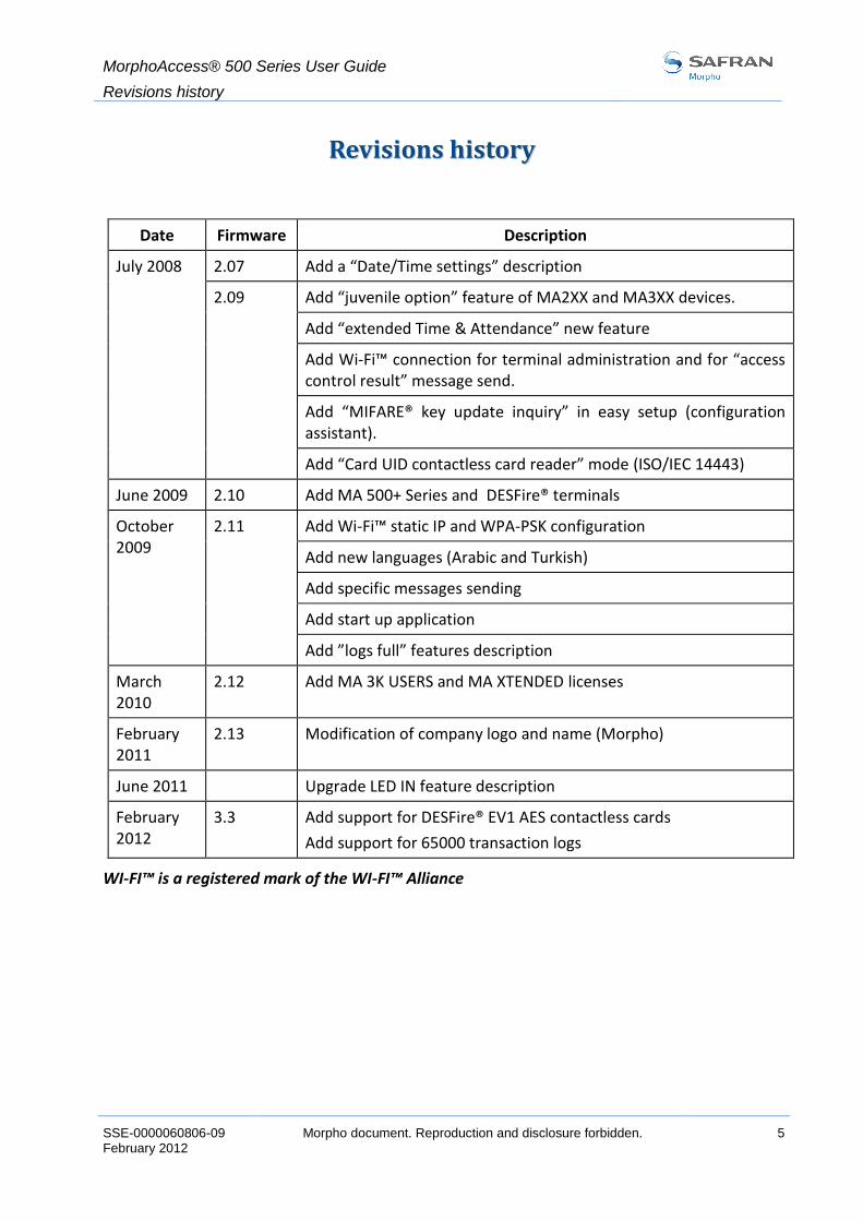
RReevviissiioonnss hhiissttoorryy
Date Firmware Description
July 2008 2.07 Add a “Date/Time settings” description
2.09 Add “juvenile option” feature of MA2XX and MA3XX devices.
Add “extended Time & Attendance” new feature
Add Wi-Fi™ connection for terminal administration and for “access control result” message send.
Add “MIFARE® key update inquiry” in easy setup (configuration assistant).
Add “Card UID contactless card reader” mode (ISO/IEC 14443)
June 2009 2.10 Add MA 500+ Series and DESFire® terminals
October 2009
2.11 Add Wi-Fi™ static IP and WPA-PSK configuration
Add new languages (Arabic and Turkish)
Add specific messages sending
Add start up application
Add ”logs full” features description
March 2010
2.12 Add MA 3K USERS and MA XTENDED licenses
February 2011
2.13 Modification of company logo and name (Morpho)
June 2011 Upgrade LED IN feature description
February 2012
3.3 Add support for DESFire® EV1 AES contactless cards
Add support for 65000 transaction logs
WI-FI™ is a registered mark of the WI-FI™ Alliance
MorphoAccess® 500 Series User Guide
Introduction
6 Morpho document. Reproduction and disclosure forbidden SSE-0000060806-09 February 2012
IInnttrroodduuccttiioonn
Congratulations for choosing the MorphoAccess® 500 Series Automatic Fingerprint Recognition Terminal.
MorphoAccess® 500 Series provides an innovative and effective solution for access control applications using Fingerprint Verification or/ and Identification.
Among a range of alternative biometric techniques, the use of finger imaging has significant advantages: each finger constitutes an unalterable physical signature, which develops before birth and is preserved until death. Unlike DNA, a finger image is unique to each individual - even identical twins.
The MorphoAccess® integrates Morpho image processing and feature matching algorithms. This technology is based on acquired knowledge during 20 years of experience in the field of biometric identification and the creation of literally millions of individual fingerprint identification records.
We believe you will find the MorphoAccess® fast, accurate, easy to use and suitable for physical access control or time and attendance.
To ensure the most effective use of your MorphoAccess®, we recommend that you read this User Guide entirely.

MorphoAccess® 500 Series User Guide
Introduction
SSE-0000060806-09 Morpho document. Reproduction and disclosure forbidden. 7 February 2012
SSccooppee ooff tthhee ddooccuummeenntt
This guide relates to the use of MorphoAccess® 500 Series terminals. MorphoAccess® 500 Series is a generic appellation which gathers MorphoAccess® terminals belonging to MA 500+ Series, OMA 500 Series and MA 500 Series. Corresponding list of products is depicted in the table below.
Biometrics
Contactless Smartcard Reader
False Finger
Detection Outdoor
MIFARE® DESFire®
MA 500+ Series
MA 500+
MA 520+ D
MA 521+ D
OMA 500 Series
OMA 520 D
OMA 521 D
OMA 520
OMA 521
MA 500 Series
MA 500
MA 520
MA 521

MorphoAccess® 500 Series User Guide
Introduction
8 Morpho document. Reproduction and disclosure forbidden SSE-0000060806-09 February 2012
SSaaffeettyy iinnssttrruuccttiioonnss
EEuurrooppee iinnffoorrmmaattiioonn
Morpho hereby declares that the MorphoAccess® has been tested and found compliant with the following listed standards as required by the EMC Directive 89/336/EEC: EN55022 (1994) / EN55024 (1998), EN300-330 (1999) and by the low voltage Directive 73/23/EEC amended by 93/68/EEC: EN60950 (2000).
These terminals are Class A devices. In a residential environment, these devices may cause interference. In this case, the user is encouraged to try to correct the interference with appropriated measures such as:
reorient or relocate the receiving antenna,
increase the separation between the equipment and receiver,
connect the equipment into an outlet on a circuit different from that to which the receiver is connected,
consult the dealer or an experienced radio/TV technician for help.
UUSSAA iinnffoorrmmaattiioonn
Responsible Party: Morpho , Le Ponant de Paris, 27, rue Leblanc – F 75512 PARIS CEDEX 15 – FRANCE
Changes or modifications not expressly approved by the party responsible for compliance could void the user’s authority to operate the equipment.
This device complies with part 15 Class A of the FCC Rules. Operation is subject to the following two conditions: (1) This device may not cause harmful interference, and (2) this device must accept any interference received, including interference that may cause undesired operation.
NOTE: This equipment has been tested and found to comply with the limits for a Class A digital device, pursuant to part 15 of the FCC Rules. These limits are designed to provide reasonable protection against harmful interference in a commercial installation. This equipment generates, uses and can radiate radio frequency energy and, if not installed and used in accordance with the instructions, may cause harmful interference to radio communications. Operation of this equipment in a residential area is likely to cause harmful interference in which case the user will be required to correct the interference at their own expense.

MorphoAccess® 500 Series User Guide
Introduction
SSE-0000060806-09 Morpho document. Reproduction and disclosure forbidden. 9 February 2012
CCaannaaddiiaann iinnffoorrmmaattiioonn
This Class A digital apparatus complies with Canadian ICES-003.
Cet appareil numérique de Classe A est conforme à la norme NMB-003 du Canada.

MorphoAccess® 500 Series User Guide
MorphoAccess® Presentation
10 Morpho document. Reproduction and disclosure forbidden SSE-0000060806-09 February 2012
MMoorrpphhooAAcccceessss®® PPrreesseennttaattiioonn
MorphoAccess® is a fingerprint identification device for physical access control, time and attendance offering both multi-factor verification and identification capabilities with unequalled level of performance.

MorphoAccess® 500 Series User Guide
MorphoAccess® Presentation
SSE-0000060806-09 Morpho document. Reproduction and disclosure forbidden. 11 February 2012
IInntteerrffaacceess pprreesseennttaattiioonn
MMaann--mmaacchhiinnee iinntteerrffaaccee
The MorphoAccess® 500 Series offers a simple and ergonomic man-machine interface dedicated to access control based on fingerprint recognition:
a high quality optical scanner to capture fingerprints (1),
a bicolor led (2),
a multi-toned buzzer,
an optional contactless smart card reader (see details in section “Scope of the document”), to read data such as the reference templates from a contactless card (3),
a keyboard for time and attendance functions, local administration, User ID seizure, PIN code seizure (4),
a 128x64 display screen (5).
Figure 1: MorphoAccess® 500 Series terminal - front view

MorphoAccess® 500 Series User Guide
MorphoAccess® Presentation
12 Morpho document. Reproduction and disclosure forbidden SSE-0000060806-09 February 2012
EElleeccttrriiccaall iinntteerrffaacceess
The terminal offers multiple interfaces dedicated to administration and control information:
a multiplexed Wiegand / Dataclock output to export the user identifier to a controller (1),
a RS422 or RS485 output (2),
a LED OUT signal output (3),
two LED IN inputs to improve integration with a Central Security Controller (4),
a relay to directly command an access (door lock) (5),
a opto-sensor to detect that the back cover has been removed (6),
a multiplexed Wiegand / Dataclock input to receive the user identifier from an external badge reader (7),
an Ethernet interface (LAN 10/100 Mbps) allowing remote communications using IP protocol for example (8),
a Power Over Ethernet Interface (LAN 10/100 Mbps) allowing remote management and supplying power (9).
Figure 2: MorphoAccess® 500 Series terminal - Connectors
The MorphoAccess® 500 Series Installation Guide describes precisely each interface and connection procedure.

MorphoAccess® 500 Series User Guide
MorphoAccess® Presentation
SSE-0000060806-09 Morpho document. Reproduction and disclosure forbidden. 13 February 2012
AAcccceessss CCoonnttrrooll SSyysstteemm ssyynnooppttiicc
TTyyppiiccaall aarrcchhiitteeccttuurree iinncclluuddiinngg aa MMoorrpphhooAAcccceessss®®,, aa HHoosstt SSyysstteemm aanndd aa
CCeennttrraall SSeeccuurriittyy CCoonnttrroolllleerr
Figure 3: Typical access control system architecture
MMoorrpphhooAAcccceessss®® bbiioommeettrriicc ddaattaabbaassee mmaannaaggeemmeenntt
The management of the MorphoAccess® internal biometric database can be done either locally (through the enrolment application), or remotely by a Host System (typically MEMS™). Those two exclusive management modes are defined as the:
Local management mode,
Remote management mode.

MorphoAccess® 500 Series User Guide
MorphoAccess® Presentation
14 Morpho document. Reproduction and disclosure forbidden SSE-0000060806-09 February 2012
MMoorrpphhooAAcccceessss®® ooppeerraattiinngg mmooddee
The MorphoAccess® works according to two exclusive operating modes.
In Stand Alone Mode (terminal networked or not), the terminal can operate two applications: Access Control or Time & Attendance. When the terminal is networked, the biometric database can be managed by a Host System and downloaded to the MorphoAccess®. When the terminal is not networked the database is managed locally.
In Proxy Mode, the terminal is remotely operated by a host application that sends individual commands to the MorphoAccess®.
MMoorrpphhooAAcccceessss®® rreessuulltt sseennddiinngg
When the biometric identification is positive, the person ID can be sent to a Central Security Controller, for further action such as opening doors.

MorphoAccess® 500 Series User Guide
MorphoAccess® Presentation
SSE-0000060806-09 Morpho document. Reproduction and disclosure forbidden. 15 February 2012
TTeerrmmiinnaall PPrreesseennttaattiioonn
A MorphoAccess® 500 Series terminal is running with 4 applications dedicated to a given need.
MMAACCCCEESSSS
This is the main application, dedicated to access control including biometric control.
It is possible to leave this application to launch another application.
The current User Guide details this application features.
EENNRROOLLMMEENNTT
This application allows enrolling users in the terminal when the database of the MorphoAccess® is not managed by an external system (Local management mode).
The created database can be saved ciphered on a USB flash drive and exported to other stand alone MorphoAccess® 500 Series.
This application can also encode some MIFARE® and/or DESFire® contactless cards with user’s finger templates (depending on terminal – see section “Scope of the document”).
A synchronisation message can be sent to a distant host to inform it about changes on biometric databases. Refer to Enrolment on terminal with synchronization section.
The User Management Password protects the execution of this application.
Please refer to Enrolment Application User Guide for more information about this application.
CCOONNFFIIGGUURRAATTIIOONN
This application allows modifying the main application parameters.
Parameters are divided into files, sections and keys.
The Terminal Configuration Password protects the execution of this application.
Please refer to Configuration Application User Guide for more information about this application.
MorphoAccess® 500 Series User Guide
MorphoAccess® Presentation
16 Morpho document. Reproduction and disclosure forbidden SSE-0000060806-09 February 2012
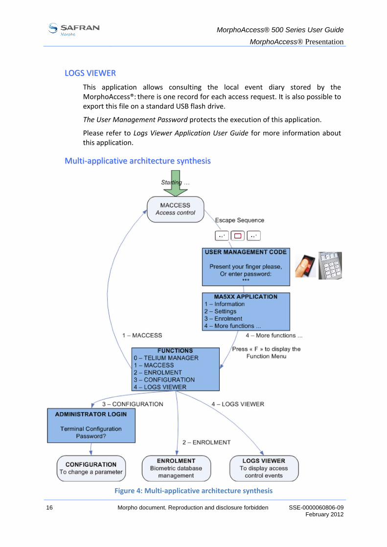
LLOOGGSS VVIIEEWWEERR
This application allows consulting the local event diary stored by the MorphoAccess®: there is one record for each access request. It is also possible to export this file on a standard USB flash drive.
The User Management Password protects the execution of this application.
Please refer to Logs Viewer Application User Guide for more information about this application.
MMuullttii--aapppplliiccaattiivvee aarrcchhiitteeccttuurree ssyynntthheessiiss
Figure 4: Multi-applicative architecture synthesis

MorphoAccess® 500 Series User Guide
MorphoAccess® Presentation
SSE-0000060806-09 Morpho document. Reproduction and disclosure forbidden. 17 February 2012
AAcccceessss ccoonnttrrooll pprreesseennttaattiioonn
The MorphoAccess® works according to two biometric recognition modes: identification or authentication. Identification and authentication can be activated at the same time (multi-factor mode).
IIddeennttiiffiiccaattiioonn ((11 vveerrssuuss NN))
The user provides one of his fingerprints and the terminal is in charge to find the user’s identifier.
In identification mode, the access request starts with a finger on the sensor.
The reference biometric templates of each allowed users are stored in the local database. The captured fingerprint is compared to all reference templates to search for a match (1 versus N matching mode). If a match is found, the user’s identifier is retrieved.
Depending on the installed license, the terminal can store up to 3000 users (2 fingers per user) in its local database or up to 50 000 users divided in 5 bases of 10 000 users each.
In this mode the sensor is always switched on, waiting for a finger.
Figure 5: Identification Mode
If the user is matched, the ID can be returned to the Central Security Controller.
If the user is not recognized, a no-match message can be sent to the Central Security Controller.
See section Access Control by Identification.

MorphoAccess® 500 Series User Guide
MorphoAccess® Presentation
18 Morpho document. Reproduction and disclosure forbidden SSE-0000060806-09 February 2012
AAuutthheennttiiccaattiioonn ((11 vveerrssuuss 11))
The user provides his identifier, and the terminal is in charge to check it by comparing a capture fingerprint with one or two references templates.
In authentication mode, the access request starts when the user’s identifier is provided.
AAuutthheennttiiccaattiioonn wwiitthh rreeffeerreennccee tteemmppllaatteess iinn ccaarrdd ((11 vveerrssuuss 11))
User biometric templates are stored (and read) on user’s contactless MIFARE® or DESFire® card.
Figure 6: Authentication Mode
If the user is matched, the ID can be returned to the Central Security Controller.
If the user is not recognized, a no-match message can be sent to the Central Security Controller.
See section Access Control by Authentication.
AAuutthheennttiiccaattiioonn wwiitthh rreeffeerreennccee tteemmppllaatteess iinn tteerrmmiinnaall ((11 vveerrssuuss 11))
The reference templates of the user are stored in the local database.
In that case, the user’s identifier is used as a search key to find the user’s templates in the local database.
The user identifier can be received in a Wiegand or a Dataclock frame, or typed on the keyboard, or read on a contactless MIFARE® or DESFire® card.
MMuullttii--FFaaccttoorr rreeccooggnniittiioonn
It is possible to combine several factors such as, what I have (a contactless smart card), what I know (PIN code), and what I am (biometric templates).

MorphoAccess® 500 Series User Guide
MorphoAccess® Presentation
SSE-0000060806-09 Morpho document. Reproduction and disclosure forbidden. 19 February 2012
PPrrooxxyy mmooddee
Proxy Mode is not strictly speaking a recognition mode. In this mode, the MorphoAccess® works as a slave waiting for external commands such as:
identification,
verification,
relay activation,
read data on a contactless card,
…
Figure 7: Proxy Mode
Chapter Proxy mode gives more information about remote management.
Please refer to MorphoAccess® Host System Interface Specification for a complete description of commands.
Proxy commands:
Identification
Verification
Relay activation
Read card
…

MorphoAccess® 500 Series User Guide
MorphoAccess® Presentation
20 Morpho document. Reproduction and disclosure forbidden SSE-0000060806-09 February 2012
RReessuulltt ooff tthhee aacccceessss ccoonnttrrooll
SSccooppee
The result of the access request is signified to the user by a specific message displayed in the screen, by a light signal, and by a sound signal.
Welcome John Doe
IDENTIFIED
or
NOT IDENTIFIED
In addition to user information, the terminal is able:
to activate an internal relay (to open a door),
to register the access request result in an internal log file,
and to send an access control result message to a distant system (usually a Central Security Controller) through several kind of communication links.
Figure 8: Send access control result message
Control result message:
RS485 or RS422
Wiegand or Dataclock
Ethernet or Wi-Fi™ (UDP / TCP / SSL)
MorphoAccess® 500 Series User Guide
MorphoAccess® Presentation
SSE-0000060806-09 Morpho document. Reproduction and disclosure forbidden. 21 February 2012
RReellaayy
If enabled, the MorphoAccess® internal relay is activated, during the specified period, in case of successful control result (access is granted).
WWiieeggaanndd//DDaattaacclloocckk sseerriiaall ppoorrtt
The access request result message can be sent through a dedicated serial port using either the Wiegand or the Dataclock protocol.
The message format includes only the user identifier (which must be a numeric value). By default, the message is sent only when the access control result is positive, but as an option this message can be sent when the result is negative, with an error code instead of the user identifier.
EEtthheerrnneett ppoorrtt
The access request result message can be sent through an IP connection using the UDP, the TCP, or the SSL protocol.
Please refer to MorphoAccess® Remote Messages Specification to know the information sent by the terminal.
For IP, the administrator can set the port and define the protocol.
Please refer to SSL Solution for MorphoAccess® documentation, for further details about the SSL on the MorphoAccess®.
WWII--FFII™™ ccoonnnneeccttiioonn
Instead of Ethernet connection, the terminal can be connected using a wireless b/g connection. Please refer to paragraphs “Network WI-FI™ configuration” and WI-FI™ configuration
The message format and the protocols supported are the same: UDP, TCP or SSL.
It is not possible for a terminal to be connected through Ethernet and through WI-FI™ at the same time.
RRSS448855//442222 sseerriiaall ppoorrtt
The access request result message (in ASCII format) can be sent through a dedicated serial port using either the RS485 or the RS422 protocol.
Please refer to MorphoAccess® Remote Messages Specification to know the information sent by the terminal.
When the serial port is used for terminal management, it is not possible to send the access request result message through this port.

MorphoAccess® 500 Series User Guide
MorphoAccess® Presentation
22 Morpho document. Reproduction and disclosure forbidden SSE-0000060806-09 February 2012
AAcccceessss rreeqquueesstt llooggggiinngg
When enabled, the terminal creates a record for each access request in a local file. Each record includes: the date/hour of the access request, the user identifier (if available) and the result of the access rights local check.
The content of this file can be downloaded by the Host System, or displayed on the terminal, or exported to a USB flash drive.
The capacity of the file is 65 000 records: when the file is full, the recording of access request result automatically stops.
The record file can be erased using the Logs Viewer embedded application. Please refer to MorphoAccess® 500 Series Logs Viewer User Guide for further details.

MorphoAccess® 500 Series User Guide
Terminal configuration
SSE-0000060806-09 Morpho document. Reproduction and disclosure forbidden. 23 February 2012
TTeerrmmiinnaall ccoonnffiigguurraattiioonn
This chapter details how to configure the MorphoAccess®. A parameter can be changed directly on the terminal or remotely through a network.
A “first start assistant” named “Easy Setup” helps the administrator to define quickly a “plug and play” configuration with an existing physical Access Control System.

MorphoAccess® 500 Series User Guide
Terminal configuration
24 Morpho document. Reproduction and disclosure forbidden SSE-0000060806-09 February 2012
EEaassyy SSeettuupp aassssiissttaanntt
AAssssiissttaanntt iinniittiiaalliizzaattiioonn
When the MorphoAccess® starts for the first time an “assistant” helps the administrator to configure easily the main functions.
EASY SETUP
GREEN: VALID
YELLOW: CORR., NEXT
RED: ABORT, PREVIOUS
NEXT
Key validates the choice.
Key corrects or goes to next step.
Key aborts operation and returns to previous step.
LLaanngguuaaggee sseelleeccttiioonn
It is possible to choose the language of the application among installed languages.
Refer to Multilingual application section for further details.
APPLICATION LANGUAGE
1 – ENGLISH
2 – SPANISH
3 – FRENCH
4 – GERMAN

MorphoAccess® 500 Series User Guide
Terminal configuration
SSE-0000060806-09 Morpho document. Reproduction and disclosure forbidden. 25 February 2012
DDaattee aanndd ttiimmee ccoonnffiigguurraattiioonn
Date and time can be configured.
Date format is MM/DD/YYYY (month/day/year).
Key deletes a character.
Key validates the selection.
ENTER DATE
08/25/200_
MM/DD/YYYY
VALID

MorphoAccess® 500 Series User Guide
Terminal configuration
26 Morpho document. Reproduction and disclosure forbidden SSE-0000060806-09 February 2012
EEtthheerrnneett iinntteerrffaaccee sseettttiinnggss
SSttaattiicc oorr ddyynnaammiicc ccoonnffiigguurraattiioonn
It is possible to choose between static or dynamic network configurations.
DHCP
1 – Enable [●]
2 – Disable [ ]
DDHHCCPP ddiissaabblleedd
If DHCP is disabled following parameters must be set:
IP address,
Network mask,
Default gateway.
ENTER IP ADDRESS
10.10.161.3_
VALID
DDHHCCPP eennaabblleedd
With DHCP only the terminal hostname on the network is required.
The DNS server must be updated so that users can communicate with the MorphoAccess® using the terminal hostname. Please contact your network administrator.
ENTER HOSTNAME
MA0789652_
VALID

MorphoAccess® 500 Series User Guide
Terminal configuration
SSE-0000060806-09 Morpho document. Reproduction and disclosure forbidden. 27 February 2012
RReeccooggnniittiioonn mmooddee
Once IP parameters are defined next step is to define the recognition mode.
Recognition mode selection screen(s) depends on the type of terminal (see section “Scope of the document”).
On terminals that do not have any contactless smartcard reader:
RECOGNITION MODE
1 – Identification [●]
Only identification mode can be selected.
On terminals equipped with a MIFARE® only contactless smartcard reader:
RECOGNITION MODE
1 – Identification [●]
2 – Contactless [ ]
3 – Multifactor [ ]
Terminal can be configured in Identification mode, Contactless authentication or Multi-factor mode (where Identification and Contactless authentication modes are merged).
MorphoAccess® 500 Series User Guide
Terminal configuration
28 Morpho document. Reproduction and disclosure forbidden SSE-0000060806-09 February 2012
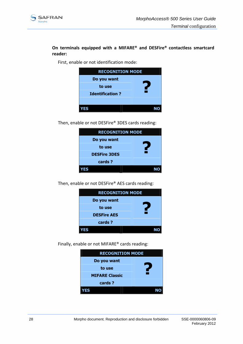
On terminals equipped with a MIFARE® and DESFire® contactless smartcard reader:
First, enable or not identification mode:
RECOGNITION MODE
Do you want
? to use
Identification ?
YES NO
Then, enable or not DESFire® 3DES cards reading:
RECOGNITION MODE
Do you want
? to use
DESFire 3DES
cards ?
YES NO
Then, enable or not DESFire® AES cards reading:
RECOGNITION MODE
Do you want
? to use
DESFire AES
cards ?
YES NO
Finally, enable or not MIFARE® cards reading:
RECOGNITION MODE
Do you want
? to use
MIFARE Classic
cards ?
YES NO
MorphoAccess® 500 Series User Guide
Terminal configuration
SSE-0000060806-09 Morpho document. Reproduction and disclosure forbidden. 29 February 2012
For example, if YES is answered to all the questions, the terminal will be in Multifactor mode (Identification + DESFire® 3DES cards + DESFire® AES cards + MIFARE® cards).
The answers for those questions also affect the type of contactless smartcards that can be encoded using Enrolment application (cf. MorphoAccess® 500 Series Enrolment Application User Guide).
If “Yes” is chosen for MIFARE® cards reading, the terminal is also able to encode MIFARE® cards.
If “Yes” is chosen for DESFire® 3DES cards reading, the terminal is also able to encode DESFire® 3DES cards unless “Yes” is chosen for DESFire® AES cards reading. In that case, the terminal is not able to encode DESFire® 3DES cards but will be able to encode DESFire® AES cards.

MorphoAccess® 500 Series User Guide
Terminal configuration
30 Morpho document. Reproduction and disclosure forbidden SSE-0000060806-09 February 2012
OOuuttppuutt iinntteerrffaaccee
Last step allows defining the interface required to export the control result.
INTERFACE PARAMETERS
1 – Wiegand [OFF]
2 – Dataclock [OFF]
3 – ID on UDP [OFF]
4 – Next
Each interface can be configured and activated independently.
Select 4 – Next to go to next step.
WWiieeggaanndd ccoonnffiigguurraattiioonn
Three protocols are available 26, 34 and 37 bits.
For other Wiegand configurations, please refer to chapter Authentication: ID input from Wiegand.
WIEGAND
1 – 26 bits [●]
2 – 34 bits [ ]
3 – 37 bits [ ]
4 – OFF [ ]
DDaattaacclloocckk ccoonnffiigguurraattiioonn
Dataclock interface can be activated – but is multiplexed with Wiegand output.
UUDDPP aaccttiivvaattiioonn
UDP remote messages can also be activated. The server IP address must be specified.
SERVER IP ADDRESS
10.10.161.7_
VALID

MorphoAccess® 500 Series User Guide
Terminal configuration
SSE-0000060806-09 Morpho document. Reproduction and disclosure forbidden. 31 February 2012
PPaasssswwoorrdd ccoonnffiigguurraattiioonn
This step consists in changing the passwords.
PASSWORDS
1 – Terminal Config.
2 – User Management
3 – Reset User Mgt.
4 – Next
Select 4 – Next to leave the assistant.
The terminal must reboot to apply the changes.
EASY SETUP END
REBOOT
THE TERMINAL?
NEXT ABORT
Press NEXT to reboot the terminal.
Press ABORT to return to password management.

MorphoAccess® 500 Series User Guide
Terminal configuration
32 Morpho document. Reproduction and disclosure forbidden SSE-0000060806-09 February 2012
CChhaannggee ooff MMIIFFAARREE®® kkeeyyss
This section only concerns MorphoAccess® equipped with a MIFARE® contactless smart card reader (see section “Scope of the document”).
This step is available since 2.09 firmware release.
The assistant proposes to replace default MIFARE® keys by custom MIFARE® keys using an Administrator card (card that contains the new MIFARE® keys).
The following screen is displayed:
Terminal config.
Do you want
? to change
MIFARE Classic
keys?
YES LATER
If the answer is YES (change keys is selected), the screen below is displayed and an administrator card must be presented:
Terminal config.
Present an Admin
! Card, please.
ABORT
As soon as the Administrator card is detected, the MIFARE® keys are automatically updated in the terminal (the update progress is signalled by successive beeps).
See MorphoAccess® 500 Series Enrolment application User guide for details about Administrator card encoding.

MorphoAccess® 500 Series User Guide
Terminal configuration
SSE-0000060806-09 Morpho document. Reproduction and disclosure forbidden. 33 February 2012
CChhaannggee ooff DDEESSFFiirree®® kkeeyyss
This section only concerns MorphoAccess® equipped with a DESFire® contactless smartcard reader (see section “Scope of the document”).
The assistant proposes to replace default DESFire® 3DES keys by custom DESFire® 3DES keys using an Administrator card (card that contains the new DESFire® 3DES keys).
The following screen is displayed:
Terminal config.
Do you want
? to change
DESFIRE 3DES
keys?
YES LATER
If the answer is YES (change keys is selected), the screen below is displayed and a 3DES DESFire® administrator card must be presented:
Terminal config.
Present an Admin
! Card, please.
ABORT
As soon as the Administrator card is detected, the DESFire® 3DES keys are automatically updated in the terminal (the update progress is signalled by successive beeps).
A similar process is then proposed for DESFire® AES keys:
Terminal config.
Do you want
? to change
DESFIRE AES
keys?
YES LATER
See MorphoAccess® 500 Series Enrolment application User guide for details about Administrator card encoding.

MorphoAccess® 500 Series User Guide
Terminal configuration
34 Morpho document. Reproduction and disclosure forbidden SSE-0000060806-09 February 2012
WWII--FFII™™ ccoonnffiigguurraattiioonn ((ssiinnccee 22..0099 ffiirrmmwwaarree rreevviissiioonn))
This step consists in configuring wireless communications in WLAN mode if a WI-FI™ USB adapter is plugged and a Wi-Fi™ licence is loaded in the MorphoAccess® (please refer to paragraph « Network WI-FI™ configuration »).
The WI-FI™ Wizard allows the followings operations:
WIFI CONFIGURATION
1 – Active profile
2 – New profile
3 – Activate profile
4 – Get profile info
WIFI CONFIGURATION
4 – Get profile info
5 – Modify profile
6 – Remove profile
7 – Next
DDiissppllaayy tthhee aaccttiivvee pprrooffiillee
The choice 1 – Active profile allows displaying the active profile (if any).
ACTIVE PROFILE
1 – TEST_MA [●]
CCrreeaattee aanndd aaccttiivvaattee aa nneeww pprrooffiillee
The choice 2 – New profile allows creating and activating a new profile. This is the first action to perform on a new terminal.
During the first step, the system searches for available WI-FI™ access points. This screen is temporary displayed:
NEW PROFILE
Scanning…

MorphoAccess® 500 Series User Guide
Terminal configuration
SSE-0000060806-09 Morpho document. Reproduction and disclosure forbidden. 35 February 2012
Then the list of access points is displayed:
CHOOSE ACCES POINT
1 – TEST_MA [●]
2 – WIFI_1 [..]
3 – other access point [..]
At the second step, an access point must be chosen, existing or not, to create the new profile.
The following menu is displayed and allows setting each parameter of the new profile:
NEW PROFILE
1 – SSID
2 – MAC address
3 – authentication
4 – algorithm
NEW PROFILE
4 – algorithm
5 – key
6 – channel
7 – valid
Several parameters are automatically initialized by the first step: SSID, MAC address, channel. Other parameters are to be initialized by the network administrator:
SSID (Service Set IDentifier) is the name of the profile,
MAC address is the access point MAC address,
the authentication can be: « open » or « shared » (only for WEP protection),
the algorithm can be: « None », « WEP64 », « WEP128 » or “WPA-PSK” (since 2.11 firmware revision),
the key to enter is an hexadecimal key with size of 10 for WEP64, 26 for WEP128, and an ASCII string of 8 up to 63 characters for WPA-PSK
the channel can be changed to avoid interferences.
If an existing access point is used, parameters have initially the values of access point parameters; for an “other access point”, parameters have default values.

MorphoAccess® 500 Series User Guide
Terminal configuration
36 Morpho document. Reproduction and disclosure forbidden SSE-0000060806-09 February 2012
If WEP or WPA algorithm is chosen, the key must be entered (the key is not retrieved from access point).
The profile must have the same value parameters as its access point.
For the selection of one of the six first choices, data capturing screens or menu screens are displayed. The choice 7 – valid allows creating and activating the profile with its parameters.
AAccttiivvaattee aa eexxiissttiinngg pprrooffiillee
The choice 3 – Activate profile allows activating an existing profile.
A screen showing the profiles saved in the MorphoAccess® is displayed and the profile to activate can be selected.
The parameters are activated after terminal restart.
The success of the WI-FI™ configuration can be checked by reading the IP address assigned by the WLAN network to the terminal: IP address must be different from 0.0.0.0., if the profile ‘s network configuration is DHCP.
DDiissppllaayy aann eexxiissttiinngg pprrooffiillee iinnffoorrmmaattiioonn
The choice 4 – Get profile info allows retrieving information about a profile.
A screen showing the profiles saved in the MorphoAccess® is displayed and the profile can be selected.
Once a profile is selected, the following screen is displayed:
NEW PROFILE
1 – SSID
2 – MAC address
3 – authentication
4 – algorithm
NEW PROFILE
4 – algorithm
5 – channel
It enables to display the value of each parameter.
MMooddiiffyy aann eexxiissttiinngg pprrooffiillee
The choice 5 – Modify profile allows modifying some parameters of a profile.

MorphoAccess® 500 Series User Guide
Terminal configuration
SSE-0000060806-09 Morpho document. Reproduction and disclosure forbidden. 37 February 2012
A screen showing the profiles saved in the MorphoAccess® is displayed and the profile can be selected.
Once a profile is selected, the following screen is displayed:
If WEP or WPA algorithm is chosen, the key must be entered (the key is not retrieved from access point).
The profile must have the same value parameters as its access point.
For the selection of one of the three first choices, data capturing screens or menu screens are displayed. The choice 4 – valid allows creating and activating the profile with its parameters.
RReemmoovvee aann eexxiissttiinngg pprrooffiillee
The choice 6 – Remove allows removing a profile.
A screen showing the profiles saved in the MorphoAccess® is displayed and the profile to remove can be selected.
CCoonnffiigguurree aaccttiivvee pprrooffiillee’’ss nneettwwoorrkk sseettttiinnggss ((ssiinnccee 22..1111 ffiirrmmwwaarree
rreevviissiioonn))
The choice 7 – Next allows choosing between static or dynamic network configurations.
DHCP
1 – Enable [●]
2 – Disable [..]
PROFILE TEST_MA
1 – authentication
2 – algorithm
3 – key
4 – valid

MorphoAccess® 500 Series User Guide
Terminal configuration
38 Morpho document. Reproduction and disclosure forbidden SSE-0000060806-09 February 2012
DHCP disabled
If DHCP is disabled following parameters must be set:
IP address,
Network mask,
Default gateway.
ENTER IP ADDRESS
10.10.161.3_
VALID
DHCP enabled
When choosing the DHCP mode, the assistant asks for the terminal hostname.
ENTER HOSTNAME
MA0789652_
VALID
The DNS server must be updated so that users can communicate with the MorphoAccess® using the terminal hostname. Please contact your network administrator.
The terminal has to be restarted to take changes in account.
Note 1: If this step is never performed, the MorphoAccess configures the Wi-Fi™ active profile in DHCP mode.
Note 2: The network configuration is only for the active profile, not for the others profiles.
RReessttaarrttiinngg WWII--FFII™™ ccoonnffiigguurraattiioonn
Wi-Fi™ configuration wizard can be restarted
By escape sequence
selecting “Wi-Fi setup” in “Settings” menu (available only when a WI-Fi™ USB adapter is plugged in).

MorphoAccess® 500 Series User Guide
Terminal configuration
SSE-0000060806-09 Morpho document. Reproduction and disclosure forbidden. 39 February 2012
RReessttaarrttiinngg ““EEaassyy SSeettuupp””
MorphoAccess® “Easy Setup” can be restarted
By escape sequence
selecting “Settings” in main application MACCESS,
selecting “Easysetup” in “Settings” menu.
MorphoAccess® 500 Series User Guide
Terminal configuration
40 Morpho document. Reproduction and disclosure forbidden SSE-0000060806-09 February 2012
AAddmmiinniissttrraattiioonn MMeennuu
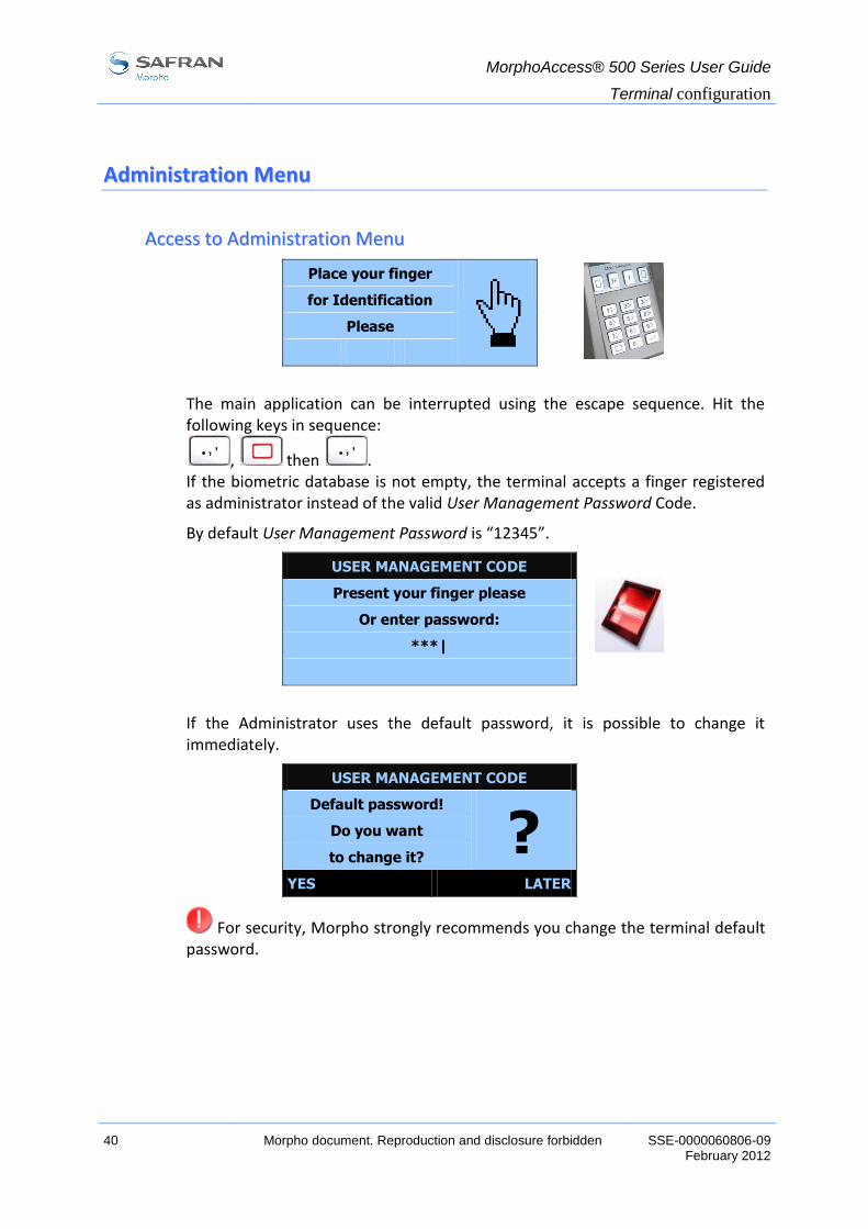
AAcccceessss ttoo AAddmmiinniissttrraattiioonn MMeennuu
Place your finger for Identification
Please
The main application can be interrupted using the escape sequence. Hit the following keys in sequence:
, then . If the biometric database is not empty, the terminal accepts a finger registered as administrator instead of the valid User Management Password Code.
By default User Management Password is “12345”.
USER MANAGEMENT CODE
Present your finger please
Or enter password:
***|
If the Administrator uses the default password, it is possible to change it immediately.
USER MANAGEMENT CODE
Default password!
? Do you want
to change it?
YES LATER
For security, Morpho strongly recommends you change the terminal default password.

MorphoAccess® 500 Series User Guide
Terminal configuration
SSE-0000060806-09 Morpho document. Reproduction and disclosure forbidden. 41 February 2012
AAddmmiinniissttrraattiioonn MMeennuu ffeeaattuurreess
MA5XX APPLICATION
1 – Information
2 – Settings
3 – Enrolment
4 – More functions…
IInnffoorrmmaattiioonn MMeennuu
MA5XX APPLICATION
1 – Information
2 – Settings
3 – Enrolment
4 – More functions…
Select Information to access the terminal and sensor information:
INFORMATION
1 – Terminal Info
2 – Sensor Info
TTeerrmmiinnaall iinnffoorrmmaattiioonn
Select Terminal Info to access to the following information:
Terminal information Description Example
1 – Type Terminal type 520
2 – Serial Number Terminal serial number 073035353A
3 – Soft. Version Terminal main software version (MACCESS)
V02.00.02
4 – IP Address Terminal IP address 134.1.32.214
5 – MAC Address Terminal MAC address 00:60:4C:69:53:53

MorphoAccess® 500 Series User Guide
Terminal configuration
42 Morpho document. Reproduction and disclosure forbidden SSE-0000060806-09 February 2012
SSeennssoorr iinnffoorrmmaattiioonn
Select Sensor Info to access the following information:
Sensor information Description Example
1 – Licence Info Licence information (licence name, Licence ID)
MA_XTENDED Device Licence ID: 251946640 0728EC51008
2 – Sensor Info Sensor information (type, flash size, serial number, sensor ID)
MSO300
Flash: 32768 Ko SN: 0730A010026
ID: 25115841-4
3 – Soft. Info Sensor software version. After a software upgrade, a reboot is necessary to get the current version.
MSO V08.02.d-C
SSeettttiinnggss mmeennuu
SETTINGS
1 – Factory Settings
2 – Easy Setup
3 – Change Passwords
4 – Wifi Setup
Factory Settings resets MorphoAccess® parameters to their default value. IP parameters are preserved.
On MorphoAccess® equipped with a MIFARE® contactless smartcard reader (see section “Scope of the document”), the terminal will ask for MIFARE® keys reset.
On MorphoAccess® equipped with a MIFARE® and DESFire® contactless smartcard reader (see section “Scope of the document”), the terminal will ask for MIFARE® keys reset, and then will ask for DESFire® keys reset.
Please refer to MorphoAccess® 500 Series Parameters Guide to know parameters default values.
Easy Setup launches “Easy Setup”.
Change Passwords allows changing system passwords.
WiFi Setup allows configuring the WI-FI™ interface. This item appears only when a WI-FI™ USB adapter is plugged in the MorphoAccess®.

MorphoAccess® 500 Series User Guide
Terminal configuration
SSE-0000060806-09 Morpho document. Reproduction and disclosure forbidden. 43 February 2012
UUnnddeerrssttaannddiinngg MMoorrpphhooAAcccceessss®® CCoonnffiigguurraattiioonn
PPrreesseennttaattiioonn
MorphoAccess® parameters are stored into files organized in sections and values.
For example a file named “app.cfg” contains all the parameters defining the main application settings.
[bio ctrl]
identification=1
nb attempts=2
…
[log file]
enabled=1
…
CCoonnffiigguurraattiioonn oorrggaanniizzaattiioonn
The application creates several files:
app.cfg,
adm.cfg,
bio.cfg,
net.cfg,
fac.cfg,
…
Please refer to MorphoAccess® Parameters Guide for further details on those files.

MorphoAccess® 500 Series User Guide
Terminal configuration
44 Morpho document. Reproduction and disclosure forbidden SSE-0000060806-09 February 2012
MMooddiiffyyiinngg aa ppaarraammeetteerr
There are two ways to modify a parameter:
directly on the terminal using the Configuration Application,
remotely through IP or Serial link with a client application running on the Host System.
NNoottaattiioonn
In this manual a parameter is presented using this format:
“Short parameter description”
file/section/parameter Value
For example to activate recognition mode based on identification, this key must be set to 1 (enabled, true, or yes when using the configuration application):
Access control by identification
app/bio ctrl/identification 1

MorphoAccess® 500 Series User Guide
Terminal configuration
SSE-0000060806-09 Morpho document. Reproduction and disclosure forbidden. 45 February 2012
MMooddiiffyyiinngg aa ppaarraammeetteerr uussiinngg tthhee CCoonnffiigguurraattiioonn AApppplliiccaattiioonn
The Configuration application allows changing a parameter directly on the terminal.
You must exit a possible running application to display the application selection menu.
If the main application is running, it must be quit using the escape sequence:
, then .
Then enter the User Management Password to access to the Administration menu.
Select “More functions …” to exit the Access Control application.
Press to display the functions menu.
Select 3 CONFIG to launch the Configuration application.
The Configuration application is fully detailed in the Configuration Application User Guide. This chapter only offers a brief description.
FUNCTIONS
1 MACCESS
2 ENROLMENT
3 CONFIG
4 LOGS VIEWER
KKeeyyss rroollee
Keys and change the current selection (up and down selection)
Key deletes a character or goes to previous screen
Key confirms the change
Key quits the application

MorphoAccess® 500 Series User Guide
Terminal configuration
46 Morpho document. Reproduction and disclosure forbidden SSE-0000060806-09 February 2012
CChhaannggiinngg aa ppaarraammeetteerr
To change a parameter, select the “Configuration…” item.
MAIN MENU
1 Configuration…
2 More…
3 Quit
A menu allows selecting the file to modify. Note that the order of the menu may change.
FILE SELECTION
1 bio
2 app
3 adm
4 net
When a file has been selected it is possible to choose a section.
[APP]
1 bio ctrl
2 contactless
3 relay
4 send ID UDP
The parameter list contains all parameters available in a section.
[APP]/BIO CTRL
1 authent ID keyboard
2 identification
3 authent card mode
4 nb attempts
It is possible to display parameters one by one in a given section.
[app]/bio ctrl
authent ID keyboard
Enabled
EDIT << >> EXIT
The edition menu depends on the parameter type.

MorphoAccess® 500 Series User Guide
Terminal configuration
SSE-0000060806-09 Morpho document. Reproduction and disclosure forbidden. 47 February 2012
NOTE: The values Enabled, True, Yes in the configuration application is equivalent to the value 1 when using the Morpho Bio Toolbox for example.
BBiinnaarryy cchhooiiccee
[app]/bio ctrl
authent ID keyboard
True [●]
False [ ]
IIPP aaddddrreessss
[app]/send ID udp
host address
134. .1 .32 .214

MorphoAccess® 500 Series User Guide
Terminal configuration
48 Morpho document. Reproduction and disclosure forbidden SSE-0000060806-09 February 2012
CCoonnffiigguurriinngg aa nneettwwoorrkkeedd MMoorrpphhooAAcccceessss®®
IInnttrroodduuccttiioonn
A PC (running with MEMS™ for example) connected to a MorphoAccess® can manage the terminal. Some available remote operations are:
Biometric record addition,
Control settings modification,
Configuration reading,
Local database deletion,
Biometric record deletion,
Control diary ( log file ) downloading,
Firmware upgrade.
The PC acts as a TCP/IP client for the MorphoAccess®.
Figure 9: Configuration of the terminal with a distant system
The MorphoAccess® works as a TCP/IP server waiting for request from a client.
The client can send biometric templates to the terminal and manage the local database.
Please refer to MorphoAccess® Host System Interface Specification for a complete description of remote administration command set. This document also explains how to create a database and store biometric records in this base.
Remote management:
Change mode
Add template
Get configuration
…
MorphoAccess® 500 Series User Guide
Terminal configuration
SSE-0000060806-09 Morpho document. Reproduction and disclosure forbidden. 49 February 2012
NNeettwwoorrkk ffaaccttoorryy sseettttiinnggss
By default the terminal IP address is 134.1.32.214. This address can be changed through IP (Morpho Bio Toolbox) or with a USB flash drive (USB Network Tool).
The default server port is 11010.
DDaattee//TTiimmee sseettttiinnggss
The date/time of the terminal can be initialized with the configuration assistant (Easy setup) or by a distant host system using an application such as the “Morpho Bio Toolbox” (“Configuration” tab, “Set date and time” button) described below.
The terminal start-up process searches for date modification and does not accept a date older than the firmware generation date. In that case, the current will be the firmware generation date.
SSSSLL sseeccuurriinngg ((ssiinnccee 22..0077 ffiirrmmwwaarree rreevviissiioonn))
This remote management TCP link can be secured using SSL. Please refer to SSL Solution for MorphoAccess® document for further details.
MMooddiiffyyiinngg aa kkeeyy uussiinngg ““MMoorrpphhoo BBiioo TToooollbbooxx””
Morpho Bio Toolbox can modify MorphoAccess® parameters. This program is an illustration of use of the TCP API. Please refer to the User Guide available in the “Help” menu of Morpho Bio Toolbox.
Figure 10: Morpho Bio Toolbox

MorphoAccess® 500 Series User Guide
Terminal configuration
50 Morpho document. Reproduction and disclosure forbidden SSE-0000060806-09 February 2012
NNeettwwoorrkk WWII--FFII™™ ccoonnffiigguurraattiioonn ((ssiinnccee 22..0099 ffiirrmmwwaarree rreevviissiioonn))
WI-FI™ connection is available under the following conditions:
a Morpho WI-FI™ USB adapter, ref. 189930722, must be plugged in the upper USB port of the terminal. Installation procedure is described in the “MorphoAccess® 500 Series Installation Guide”,
a MorphoAccess® WI-FI™ Licence is loaded in the terminal ( cf. paragraph “Downloading a licence“),
the terminal must not be connected to a network with an Ethernet cable: WI-FI™ connection and Ethernet cable connection are mutually exclusive.
Note 1: A DHCP server and a DNS server are mandatory when the Wi-Fi™ interface is configured in DHCP mode.
The DHCP server automatically attributes an IP address to the MorphoAccess®.
The DNS server links the MorphoAccess® hostname to its real IP address.
It is also important that the DNS server is updated each time the DHCP server attributes another IP address to a MorphoAccess®.
Note 2: A MorphoAccess® WI-FI™ Licence is mandatory.
If WI-FI™ USB adapter is plugged in and if there is no license present, the MorphoAccess® will display the following screen before restarting:
SETTINGS
No valid licence for
WIFI
Terminal will restart
To solve this issue, unplug the WI-FI™ USB adapter and restart the terminal and load a Wi-Fi™ license.
See WI-FI™ parameters description in paragraph “WI-FI™ configuration

MorphoAccess® 500 Series User Guide
Terminal configuration
SSE-0000060806-09 Morpho document. Reproduction and disclosure forbidden. 51 February 2012
DDoowwnnllooaaddiinngg aa lliicceennccee
By default the MorphoAccess® can match a fingerprint against a database of 3000 users. This database configuration corresponds to a basic license (MA_3K_USERS).
MA-Xtended™ licence (MA_XTENDED) extends MorphoAccess® recognition capabilities to 5 databases of 10000 users (2 fingers per user) or 16 databases of 3000 users.
WI-FI™ network (WLAN) use is enabled with another license.
License number depends on the Device Licence ID. This unique identifier is checked by the Licence Manager tool. It can be displayed on the “information” menu.
The Licence Manager tool allows downloading a licence in the MorphoAccess® as explained in Terminal Licence Management documentation. Note: MA_3K_USERS licence corresponds to the former MSO_MA_IDENTLITE one. MA_XTENDED licence corresponds to the former MSO_MA_IDENTPLUS one. Note: Since 2.12 firmware revision, the MorphoAccess® 500 Series terminals handle MA_3K_USERS and MA_XTENDED licences, but also MSO_MA_IDENTLITE and MSO_MA_IDENTPLUS licences for backward compatibility.

MorphoAccess® 500 Series User Guide
Terminal configuration
52 Morpho document. Reproduction and disclosure forbidden SSE-0000060806-09 February 2012
UUppggrraaddiinngg tthhee ffiirrmmwwaarree
It is possible to upgrade your MorphoAccess® firmware through IP.
The firmware is available on the CDROM or on Morpho Website.
Use the MorphoAccess Quickloader to upgrade terminal system.
Please refer to the MorphoAccess® Upgrade Tools User Guide for more information about upgrade procedures.

MorphoAccess® 500 Series User Guide
Terminal configuration
SSE-0000060806-09 Morpho document. Reproduction and disclosure forbidden. 53 February 2012
SSccrreeeenn ccoonnttrraasstt
A keyboard shortcut controls the screen contrast.
Key and increase the screen contrast
Key and reduce the screen contrast

MorphoAccess® 500 Series User Guide
Terminal configuration
54 Morpho document. Reproduction and disclosure forbidden SSE-0000060806-09 February 2012
SSttaarrttiinngg uupp aapppplliiccaattiioonn
By default, the MorphoAccess® 500 Series terminal starts on the access control application (MACCESS). But it can also start on another application:
Starting up application
exe/init state/startup 1
(MACCESS application)
The following choices are allowed:
Start on MACCESS application
Start on ENROLMENT application
Start on applications list.
Please refer to MorphoAccess® Parameters Guide.

MorphoAccess® 500 Series User Guide
Stand Alone Modes (Networked or not)
SSE-0000060806-09 Morpho document. Reproduction and disclosure forbidden. 55 February 2012
SSttaanndd AAlloonnee MMooddeess ((NNeettwwoorrkkeedd oorr nnoott))
The MorphoAccess® works according to two biometric recognition modes: identification or authentication. Identification and authentication can be activated at the same time (multi-factor mode).
In Stand Alone Mode, the terminal can operate two applications: Access Control or Time & Attendance.

MorphoAccess® 500 Series User Guide
Stand Alone Modes (Networked or not)
56 Morpho document. Reproduction and disclosure forbidden SSE-0000060806-09 February 2012
PPRREELLIIMMIINNAARRYY:: aaddddiinngg aa bbiioommeettrriicc tteemmppllaattee iinn llooccaall ddaattaabbaassee
The management of the MorphoAccess® internal biometric database can be done either locally (through the enrolment application), or remotely by a Host System. Those two exclusive management modes are defined as following:
Local management mode,
Remote management mode.
LLooccaall eennrroollmmeenntt
The Enrolment Application is dedicated to this function.
The local database can be exported ciphered to other MorphoAccess® 500 Series devices using a USB flash drive.
Contactless cards containing user templates can be generated using this application.
A message can be sent to a distant host to inform that changes were made on the MorphoAccess® internal biometric database. Then changes can be exported to the host centralized database. (cf. Enrolment on terminal with synchronization)
Please refer to Enrolment Application User Guide for a complete description of local enrolment features.

MorphoAccess® 500 Series User Guide
Stand Alone Modes (Networked or not)
SSE-0000060806-09 Morpho document. Reproduction and disclosure forbidden. 57 February 2012
RReemmoottee mmaannaaggeemmeenntt
The user is enrolled on an Enrolment Station (typically a PC station with MEMS™) and biometric templates are exported to the MorphoAccess® via a communication link.
Figure 11: Remote management
This architecture allows managing many MorphoAccess® databases from one PC client station.

MorphoAccess® 500 Series User Guide
Stand Alone Modes (Networked or not)
58 Morpho document. Reproduction and disclosure forbidden SSE-0000060806-09 February 2012
MMAACCCCEESSSS aapppplliiccaattiioonn:: aacccceessss ccoonnttrrooll oorr TTiimmee && AAtttteennddaannccee
MorphoAccess® application can be configured to work in physical access control mode or in time and attendance mode. In this configuration, each MorphoAccess® event logged includes some attendance information (entry, exit...).
When the time and attendance feature is activated, the main screen may display 2 or 4 functions or a bitmap file.
TTwwoo ffuunnccttiioonnss mmooddee::
Time and Attendance (2 functions)
app/modes/time and attendance 1
TIME ATTENDANCE
15:27
OCT 08 2006
Green key: IN selection
Yellow key: OUT selection

MorphoAccess® 500 Series User Guide
Stand Alone Modes (Networked or not)
SSE-0000060806-09 Morpho document. Reproduction and disclosure forbidden. 59 February 2012
FFoouurr ffuunnccttiioonnss mmooddee::
Time and Attendance (4 functions)
app/modes/time and attendance 2
TIME ATTENDANCE
15:26
OCT 08 2006
Green key: IN selection
“up” key: Temporary IN selection (come back)
“down” key: Temporary OUT selection
Yellow key: OUT selection
When entering, the user has to press key to log his entry time.
When exiting, the user has to press key to log his exit time.
For particular uses such as temporary absences, two additional functions corresponding to “function” keys 2 and 3 can be displayed.
MorphoAccess® 500 Series User Guide
Stand Alone Modes (Networked or not)
60 Morpho document. Reproduction and disclosure forbidden SSE-0000060806-09 February 2012
EExxtteennddeedd mmooddee::
Extended Time and Attendance
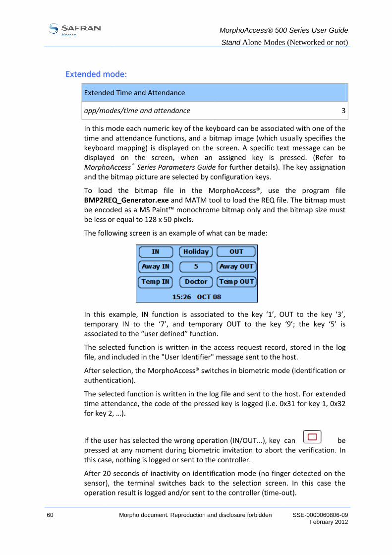
app/modes/time and attendance 3
In this mode each numeric key of the keyboard can be associated with one of the time and attendance functions, and a bitmap image (which usually specifies the keyboard mapping) is displayed on the screen. A specific text message can be displayed on the screen, when an assigned key is pressed. (Refer to MorphoAccess® Series Parameters Guide for further details). The key assignation and the bitmap picture are selected by configuration keys.
To load the bitmap file in the MorphoAccess®, use the program file BMP2REQ_Generator.exe and MATM tool to load the REQ file. The bitmap must be encoded as a MS Paint™ monochrome bitmap only and the bitmap size must be less or equal to 128 x 50 pixels.
The following screen is an example of what can be made:
In this example, IN function is associated to the key ‘1’, OUT to the key ‘3’, temporary IN to the ‘7’, and temporary OUT to the key ‘9’; the key ‘5’ is associated to the “user defined” function.
The selected function is written in the access request record, stored in the log file, and included in the "User Identifier" message sent to the host.
After selection, the MorphoAccess® switches in biometric mode (identification or authentication).
The selected function is written in the log file and sent to the host. For extended time attendance, the code of the pressed key is logged (i.e. 0x31 for key 1, 0x32 for key 2, …).
If the user has selected the wrong operation (IN/OUT...), key can be pressed at any moment during biometric invitation to abort the verification. In this case, nothing is logged or sent to the controller.
After 20 seconds of inactivity on identification mode (no finger detected on the sensor), the terminal switches back to the selection screen. In this case the operation result is logged and/or sent to the controller (time-out).

MorphoAccess® 500 Series User Guide
Stand Alone Modes (Networked or not)
SSE-0000060806-09 Morpho document. Reproduction and disclosure forbidden. 61 February 2012
To disable Time Attendance mode set app/modes/time and attendance to 0.
NOTE: The icon set used for the time and attendance mode is customizable. Icons from old MorphoAccess® 200 and 300 Series can be displayed instead of the new ones (Refer to MorphoAccess® Series Parameters Guide for further details).
NNoottee aabboouutt tteerrmmiinnaall cclloocckk ddeevviiaattiioonn
The terminal clock has a +/- 4 sec per day typical time deviation at +25°C. At 50°C, the time deviation may be up to -8 sec per day.
For application requiring time precision (such as SSL, DESFire®), MorphoAccess® clock must be synchronized regularly with an external clock.

MorphoAccess® 500 Series User Guide
Stand Alone Modes (Networked or not)
62 Morpho document. Reproduction and disclosure forbidden SSE-0000060806-09 February 2012
AAcccceessss ccoonnttrrooll bbyy iiddeennttiiffiiccaattiioonn
Access control by identification
app/bio ctrl/identification 1
To configure the MorphoAccess® in this mode, set the parameter app/bio ctrl/identification to 1.
After starting, the MorphoAccess® waits for fingerprint detection in identification mode. The sensor is lighted on.
Place your finger for Identification
Please
The user presents a finger to start identification process.
Remove finger Analyzing …
If the identification is successful, the terminal triggers the access or returns the corresponding ID to central security controller.
The ID can be sent through various interfaces. Please refer to MorphoAccess® Remote Messages Specification for a complete description of “hit” and “no hit” messages.
Result is displayed on terminal screen.
Welcome John Doe
Identified.
Once the user identification is done, the terminal automatically loops back and waits for a new finger.
At least one user (biometric template) must be stored in the local database.

MorphoAccess® 500 Series User Guide
Stand Alone Modes (Networked or not)
SSE-0000060806-09 Morpho document. Reproduction and disclosure forbidden. 63 February 2012
If the terminal is running in identification mode with an empty database, the sensor is off and the following screen is displayed.
Empty Database Please contact
Administrator
DDiissaabblliinngg iiddeennttiiffiiccaattiioonn
Set app/bio ctrl/identification to 0 to disable identification.

MorphoAccess® 500 Series User Guide
Stand Alone Modes (Networked or not)
64 Morpho document. Reproduction and disclosure forbidden SSE-0000060806-09 February 2012
AAcccceessss ccoonnttrrooll bbyy iiddeennttiiffiiccaattiioonn ((MMAA--XXtteennddeedd lliicceennccee llooaaddeedd))
It is possible to increase MorphoAccess® 500 Series biometric database size thanks to a licence (MA-Xtended licence): the MorphoAccess® then manages 5 bases of 10 000 users or 16 databases of 3 000 users.
Access control by identification with MA-Xtended licence
app/bio ctrl/identification 1
To configure the MorphoAccess® in this mode, set the parameter app/bio ctrl/identification to 1 (Enabled, True, Yes when using the configuration application) and verify that MA-Xtended licence has been loaded.
Please refer to chapter Downloading a licence to know how to upgrade the MorphoAccess® with MA-Xtended licence.
After starting, the MorphoAccess® waits for fingerprint detection in identification mode. The sensor is lighted on.
If an MA-Xtended licence is loaded it is possible to choose the active database.
To select a user database, press a key number to toggle the database number. By default, databases 0 to 4 can be selected and used.
Database 0 is the default database.
Place your finger for Identification
Please
4 14:25
The user can present a finger to launch identification process.
If the identification is successful, the terminal triggers the access or returns the corresponding ID to Central Security Controller.
Once the user identification is done, the terminal automatically loops back to database 0 and waits for a new finger.
At least one fingerprint must be stored in the local database.

MorphoAccess® 500 Series User Guide
Stand Alone Modes (Networked or not)
SSE-0000060806-09 Morpho document. Reproduction and disclosure forbidden. 65 February 2012
If the selected database is empty or does not exist, the sensor is off and the following screen is displayed, before returning to the database 0.
Empty Database Please contact
Administrator
2
Set app/bio ctrl/identification to 0 to disable identification.
DDaattaabbaassee nnuummeerraattiioonn
MA-Xtended licence extends biometric database capacity from 1 base of 3 000 users to 5 bases of 10 000 users. In this configuration the user must select his database number (from 0 to 4) before presenting a finger to launch identification process.
For MorphoAccess® 300 Series user convenience, it is also possible to activate a “16 databases mode”. In this mode the user selects a database number between 0 and 15, and presents a finger to launch identification process.
The base identification is a two-digit number, with a leading zero when required. The default-selected base is the base with identification “00”.
Numeric keys allow selecting a database from 0 to 9. To select database 3,
press .
Key allows selecting a database from 10 to 15. To select database 13,
press then .
Valid base numbers are from 0 to 15. If the selected base number is higher than “15”, the number of the default base (0) is automatically forced.
Database numeration
app/G.U.I/database conversion 500 for 5 databases mode
300 for 16 databases mode
MorphoAccess® 500 Series User Guide
Stand Alone Modes (Networked or not)
66 Morpho document. Reproduction and disclosure forbidden SSE-0000060806-09 February 2012
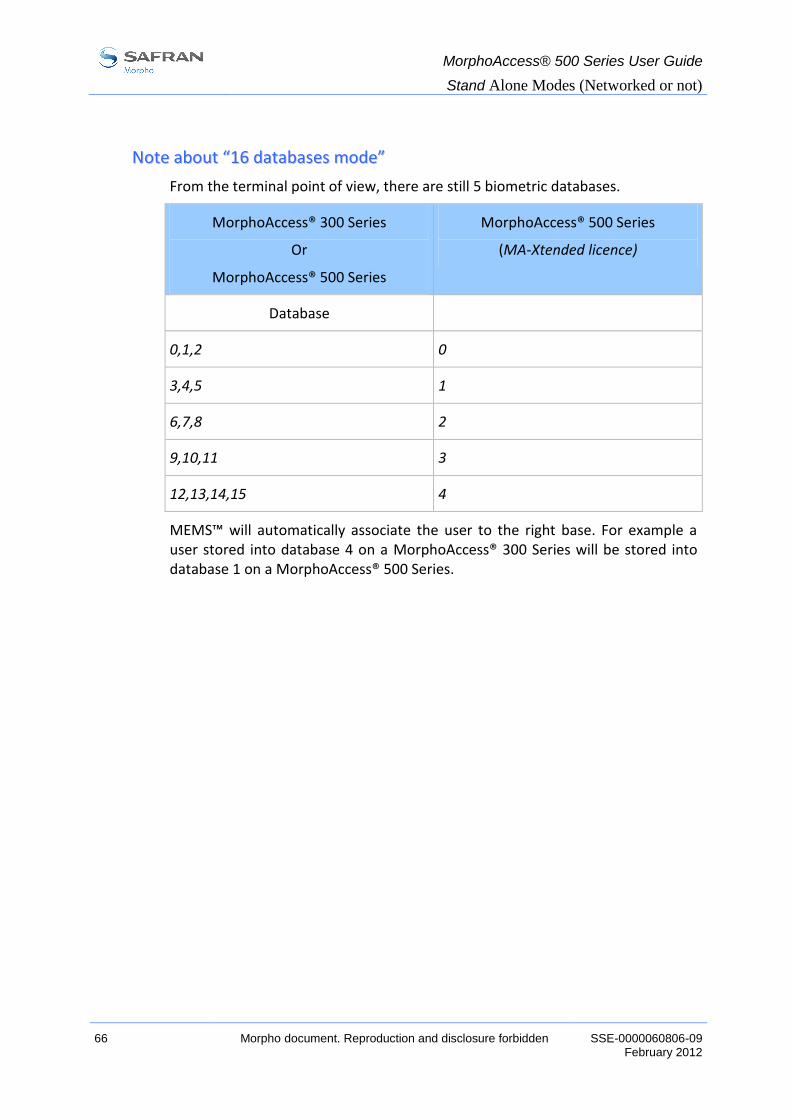
NNoottee aabboouutt ““1166 ddaattaabbaasseess mmooddee””
From the terminal point of view, there are still 5 biometric databases.
MorphoAccess® 300 Series
Or
MorphoAccess® 500 Series
MorphoAccess® 500 Series
(MA-Xtended licence)
Database
0,1,2 0
3,4,5 1
6,7,8 2
9,10,11 3
12,13,14,15 4
MEMS™ will automatically associate the user to the right base. For example a user stored into database 4 on a MorphoAccess® 300 Series will be stored into database 1 on a MorphoAccess® 500 Series.
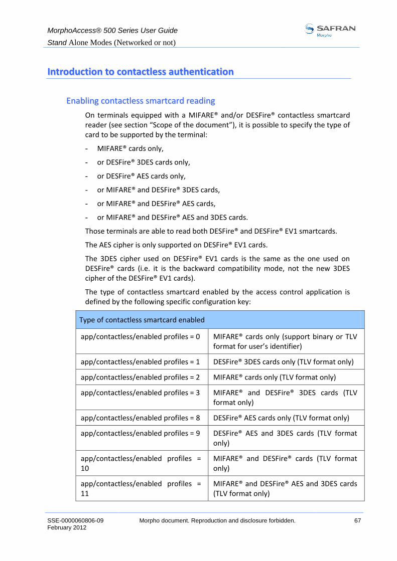
MorphoAccess® 500 Series User Guide
Stand Alone Modes (Networked or not)
SSE-0000060806-09 Morpho document. Reproduction and disclosure forbidden. 67 February 2012
IInnttrroodduuccttiioonn ttoo ccoonnttaaccttlleessss aauutthheennttiiccaattiioonn
EEnnaabblliinngg ccoonnttaaccttlleessss ssmmaarrttccaarrdd rreeaaddiinngg
On terminals equipped with a MIFARE® and/or DESFire® contactless smartcard reader (see section “Scope of the document”), it is possible to specify the type of card to be supported by the terminal:
- MIFARE® cards only,
- or DESFire® 3DES cards only,
- or DESFire® AES cards only,
- or MIFARE® and DESFire® 3DES cards,
- or MIFARE® and DESFire® AES cards,
- or MIFARE® and DESFire® AES and 3DES cards.
Those terminals are able to read both DESFire® and DESFire® EV1 smartcards.
The AES cipher is only supported on DESFire® EV1 cards.
The 3DES cipher used on DESFire® EV1 cards is the same as the one used on DESFire® cards (i.e. it is the backward compatibility mode, not the new 3DES cipher of the DESFire® EV1 cards).
The type of contactless smartcard enabled by the access control application is defined by the following specific configuration key:
Type of contactless smartcard enabled
app/contactless/enabled profiles = 0 MIFARE® cards only (support binary or TLV format for user’s identifier)
app/contactless/enabled profiles = 1 DESFire® 3DES cards only (TLV format only)
app/contactless/enabled profiles = 2 MIFARE® cards only (TLV format only)
app/contactless/enabled profiles = 3 MIFARE® and DESFire® 3DES cards (TLV format only)
app/contactless/enabled profiles = 8 DESFire® AES cards only (TLV format only)
app/contactless/enabled profiles = 9 DESFire® AES and 3DES cards (TLV format only)
app/contactless/enabled profiles = 10
MIFARE® and DESFire® cards (TLV format only)
app/contactless/enabled profiles = 11
MIFARE® and DESFire® AES and 3DES cards (TLV format only)

MorphoAccess® 500 Series User Guide
Stand Alone Modes (Networked or not)
68 Morpho document. Reproduction and disclosure forbidden SSE-0000060806-09 February 2012
CCoommppaattiibbiilliittyy wwiitthh ““AAuutthheennttiiccaattiioonn”” mmooddeess
Using a binary value read on the card as user’s identifier is allowed only with MIFARE® smart cards, and when the “app/contactless/enabled profiles” configuration key is set to 0 (zero).
All other values of this configuration keys requires TLV formatted data, as described in the MorphoAccess® terminals Contactless Card Specification document.

MorphoAccess® 500 Series User Guide
Stand Alone Modes (Networked or not)
SSE-0000060806-09 Morpho document. Reproduction and disclosure forbidden. 69 February 2012
RReeccooggnniittiioonn mmooddeess
Various recognition modes using contactless card can be applied depending on the templates location (card or terminal database) and the required security level.
Recognition with DESFire® cards supposes that the user swipes a DESFire® (depending on configuration) card containing some structured data (identifier, biometric templates, PIN code...).
Recognition with MIFARE® cards supposes that the user swipes a MIFARE® card containing some structured data (identifier, biometric templates, PIN code...). Data are localized on the card by a block (“B” parameter) and are protected by a key (defined by “C” parameter). The “C” parameter defines which key is used during the authentication with the card.
For a complete description of card structure and access mode, please refer to MorphoAccess® Contactless Card Specification.
The following recognition modes are available:
AAuutthheennttiiccaattiioonn wwiitthh bbiioommeettrriicc tteemmppllaatteess oonn ccaarrdd
Captured fingerprints are matched against templates read on the card (PK). User identifier and user biometric templates must be stored on the card.
In this mode it is also possible to check a PIN code before the authentication and to replace the biometric authentication by a BIOPIN code check. The BIOPIN code is used when user biometric templates are not available (a visitor for example).
AAuutthheennttiiccaattiioonn wwiitthh bbiioommeettrriicc tteemmppllaatteess oonn llooccaall ddaattaabbaassee
Captured fingerprints are matched against templates read from the local database. Only the user identifier is required on the card.
AAuutthheennttiiccaattiioonn bbaasseedd oonn ““ttaagg”” ccaarrdd mmooddee
Depending on the card mode, either templates are read on the card or the control can be bypassed (visitor mode). The card mode tag must be stored on the card.
It is possible to check PIN code before the authentication and to replace the biometric authentication by a BIOPIN check.
It is also possible to skip the biometric control: in this case the terminal acts as a contactless card reader.
Contactless authentication can be combined with a local identification (multi-factor mode).

MorphoAccess® 500 Series User Guide
Stand Alone Modes (Networked or not)
70 Morpho document. Reproduction and disclosure forbidden SSE-0000060806-09 February 2012
AAuutthheennttiiccaattiioonn wwiitthh bbiioommeettrriicc tteemmppllaatteess oonn ccaarrdd
Authentication with biometric templates on contactless card
app/bio ctrl/authent PK contactless 1 (Enabled)
Terminals equipped with a contactless smartcard reader (see section “Scope of the document”) can work in contactless authentication mode: the user presents his card, the terminal reads the reference biometric templates on the card and launches a biometric control based on the read templates.
In that case, the card must contain the user identifier and biometric templates: no local database is required.
To trigger authentication, the user presents his card to the terminal.
Please Present Contactless
Smart Card
If the card contains user templates, the user is invited to present his finger for biometric authentication.
Place your finger For Authentication
Please
If the authentication is successful, the terminal triggers the access or returns the corresponding ID to the Central Security Controller.
Once the user authentication is finished, the terminal automatically loops back and waits for a new card presentation.
RReeqquuiirreedd ttaaggss oonn ccaarrdd
ID CARD MODE
PK1 PK2 PIN BIOPIN
Contactless authentication Yes No Yes Yes No No
Card structure is described in MorphoAccess® Contactless Card Specification.

MorphoAccess® 500 Series User Guide
Stand Alone Modes (Networked or not)
SSE-0000060806-09 Morpho document. Reproduction and disclosure forbidden. 71 February 2012
PPIINN vveerriiffiiccaattiioonn –– PPIINN ssttoorreedd oonn ccaarrdd
If a reference PIN code is stored on the card, it is possible to check this code before controlling the fingerprints.
PIN code verification
app/bio ctrl/control PIN 1 (Yes)
To trigger authentication, the user presents his card to the terminal.
Please Present Contactless
Smart Card
If card contains a PIN code, the user is invited to enter his PIN code.
Please enter PIN
***
VAL COR
If the PIN code is correct, the user is invited to present his finger for biometric authentication.
Place your finger For Authentication
Please
If the authentication is successful, the terminal triggers the access or returns the corresponding ID to the Central Security Controller.
It is also possible to activate this mode independently of biometric authentication. In this case, only the PIN code is checked.
RReeqquuiirreedd ttaaggss oonn ccaarrdd
ID CARD MODE
PK1 PK2 PIN BIOPIN
PIN code verification Yes No No No Yes No
PIN then authentication Yes No Yes Yes Yes No

MorphoAccess® 500 Series User Guide
Stand Alone Modes (Networked or not)
72 Morpho document. Reproduction and disclosure forbidden SSE-0000060806-09 February 2012
BBIIOOPPIINN vveerriiffiiccaattiioonn -- BBIIOOPPIINN ssttoorreedd oonn ccaarrdd
In this mode the card should contain a BIOPIN code. The goal of this code is to replace fingerprints authentication by BIOPIN code verification.
BIOPIN code verification
app/bio ctrl/BIOPIN enabled 1 (Yes)
This mode must be activated with the authentication that uses fingerprints from contactless card (“authent PK Contactless” to 1). The terminal looks for finger templates stored on the card. If there aren’t any, it looks for a BIOPIN code.
To trigger the BIOPIN code verification, the user presents his card to the terminal.
If the card contains a user BIOPIN, the user is invited to enter it.
Please enter biometric PIN
***
VAL COR
If the BIOPIN is correct, the terminal triggers the access or returns the user ID to the Central Security Controller.
This mode can be combined with a preliminary PIN code verification.
RReeqquuiirreedd ttaaggss oonn ccaarrdd
ID CARD MODE
PK1 PK2 PIN BIOPIN
BIOPIN code verification Yes No No No No Yes

MorphoAccess® 500 Series User Guide
Stand Alone Modes (Networked or not)
SSE-0000060806-09 Morpho document. Reproduction and disclosure forbidden. 73 February 2012
AAuutthheennttiiccaattiioonn wwiitthh bbiioommeettrriicc tteemmppllaatteess iinn llooccaall ddaattaabbaassee
In this mode, only the ID (Identifier) is read on the card. If the ID exists in the biometric database, the MorphoAccess® performs an authentication using the biometric templates associated to this ID.
The ID can be stored into a TLV structure (typically a card encoded by MEMS™) or directly read at a given offset of the card (binary ID).
AASSCCIIII IIDD,, ssttrruuccttuurreedd ddaattaa
Contactless authentication with templates on local database
app/bio ctrl/authent ID contactless 1 (Enabled)
The identifier must be stored into a TLV structure.
ASCII identifier in tagged structure.
app/contactless/data format
app/contactless/data length
app/contactless/data offset
0 (structured data)
0
0
The user identifier is used as an index in the local database of the MorphoAccess®: reference biometric templates are stored in the local database.
To trigger authentication, the user presents his card to the terminal.
Please Present Contactless
Smart Card
If the corresponding ID exists in the terminal database, the user is invited to place his finger for biometric authentication.
Place your finger For Authentication
Please
If the authentication is successful, the terminal triggers the access or returns the corresponding ID to the Central Security Controller.
Once the user authentication is done, the terminal automatically loops back and waits for a new card presentation.

MorphoAccess® 500 Series User Guide
Stand Alone Modes (Networked or not)
74 Morpho document. Reproduction and disclosure forbidden SSE-0000060806-09 February 2012
RReeqquuiirreedd ttaaggss oonn ccaarrdd
ID CARD MODE
PK1 PK2 PIN BIOPIN
authent ID contactless Yes No No No No No
Note: a non-empty database must exist in the terminal.
BBiinnaarryy iiddeennttiiffiieerr,, nnoonn--ssttrruuccttuurreedd ddaattaa
This mode can not be used when card profile reading is configured (cf. Enabling contactless smartcard reading).
Contactless authentication with templates on local database
app/bio ctrl/authent ID contactless 1 (Enabled)
In this mode the identifier is read at a given offset on the card and is supposed to be binary. No TLV structure is required on the card.
It is possible to read non-byte aligned data. It is useful to read a user ID included in a Wiegand data or to use the card serial number as an identifier.
Binary identifier, non-structured data
app/contactless/data format 1 (binary data)
Binary data are defined by their position from the first read block.
ID length is limited to 8 bytes (app/contactless/data length 8.0).
ID offset is limited to 15 bytes (app/contactless/data offset 15.0).
Data localization
app/contactless/B
app/contactless/data length
app/contactless/data offset
[1-215]: read block
[number of bytes].[additional bits]
[number of bytes].[additional bits]
The interpretation of the data can be defined.
Data interpretation
app/contactless/data type
0.1 (binary data, MSB first)
0.0 (binary data, LSB first RFU)
The user identifier is used as an index in the local database of the MorphoAccess®: in this case reference biometric templates are stored in the local database.

MorphoAccess® 500 Series User Guide
Stand Alone Modes (Networked or not)
SSE-0000060806-09 Morpho document. Reproduction and disclosure forbidden. 75 February 2012
Authentication process is exactly the same as the one presented above.
Example – 4 bytes identifier.
The terminal is configured to read 4 bytes.
Read bytes are F4 E1 65 34.
Corresponding user identifier in the local database is “4108412212” (ASCII).
Example – reading a MIFARE® smartcard Serial Number (big endian format).
app/contactless/data format = 1
app/contactless/data type = 0.1
app/contactless/data length = 4.0
app/contactless/data offset = 0.0
app/contactless/B = 1
Example – reading 32-bits identifier in a complete Wiegand frame.
The card contains at sector 15 a complete 37 bits Wiegand frame (including parity bits, site code).
On this example a 32 bits identifier begins at bit four, parity bits are noted “P”.
Sector 15
Byte 0
Byte 4
0 1 2 3 4 5 6 7 8 9 10 30 31 32 33 34 35 36 37 38 39
P Site 32 bits ID … … ID P
The corresponding configuration will read only the 32 bits ID on the card.
app/contactless/data format = 1
app/contactless/data type = 0.1
app/contactless/data length = 4.0
app/contactless/data offset = 0.4
app/contactless/B = 46
Binary identifier
Binary identifier read in MSB
4 bytes length
ID begins bit 4 of sector 15
Read at sector 15
It is possible to configure the MorphoAccess® Wiegand output to add parity bits.

MorphoAccess® 500 Series User Guide
Stand Alone Modes (Networked or not)
76 Morpho document. Reproduction and disclosure forbidden SSE-0000060806-09 February 2012
AAuutthheennttiiccaattiioonn bbaasseedd oonn ccaarrdd mmooddee
Contactless authentication with card mode
app/bio ctrl/authent card mode 1 (Enabled)
In this mode the card decides on the control progress.
The CARD MODE tag is required. This tag can take several values.
PKS [0x02]: the user identifier, template 1 and template 2 are required on the card. Biometric authentication is triggered with biometric templates. If a BIOPIN is present instead of templates, BIOPIN is controlled.
ID_ONLY [0x01]: only the user identifier is required. There is no biometric control, the control is immediately positive. This feature is useful for visitor requiring an access without enrolment. But it is still possible to store templates on the card.
PIN_CODE [0x10]: only PIN code is controlled.
PIN_THEN_PKS [0x12]: PIN code is controlled then templates or BIOPIN.
To enable this mode set app/bio ctrl/authent card mode to 1.
To disable this mode set app/bio ctrl/authent card mode to 0.
RReeqquuiirreedd ttaaggss oonn ccaarrdd iiff CCAARRDD MMOODDEE ttaagg vvaalluuee iiss PPKKSS..
ID CARD MODE
PK1 PK2 PIN BIOPIN
authent card mode (PKS) Yes Yes Yes Yes No No
authent card mode (PKS) (BIOPIN)
Yes Yes No No No Yes
RReeqquuiirreedd ttaaggss oonn ccaarrdd iiff CCAARRDD MMOODDEE ttaagg vvaalluuee iiss IIDD__OONNLLYY..
ID CARD MODE
PK1 PK2 PIN BIOPIN
authent card mode (ID_ONLY) Yes Yes No No No No
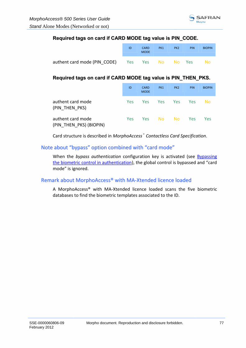
MorphoAccess® 500 Series User Guide
Stand Alone Modes (Networked or not)
SSE-0000060806-09 Morpho document. Reproduction and disclosure forbidden. 77 February 2012
RReeqquuiirreedd ttaaggss oonn ccaarrdd iiff CCAARRDD MMOODDEE ttaagg vvaalluuee iiss PPIINN__CCOODDEE..
ID CARD MODE
PK1 PK2 PIN BIOPIN
authent card mode (PIN_CODE) Yes Yes No No Yes No
RReeqquuiirreedd ttaaggss oonn ccaarrdd iiff CCAARRDD MMOODDEE ttaagg vvaalluuee iiss PPIINN__TTHHEENN__PPKKSS..
ID CARD MODE
PK1 PK2 PIN BIOPIN
authent card mode (PIN_THEN_PKS)
Yes Yes Yes Yes Yes No
authent card mode (PIN_THEN_PKS) (BIOPIN)
Yes Yes No No Yes Yes
Card structure is described in MorphoAccess® Contactless Card Specification.
NNoottee aabboouutt ““bbyyppaassss”” ooppttiioonn ccoommbbiinneedd wwiitthh ““ccaarrdd mmooddee””
When the bypass authentication configuration key is activated (see Bypassing the biometric control in authentication), the global control is bypassed and “card mode” is ignored.
RReemmaarrkk aabboouutt MMoorrpphhooAAcccceessss®® wwiitthh MMAA--XXtteennddeedd lliicceennccee llooaaddeedd
A MorphoAccess® with MA-Xtended licence loaded scans the five biometric databases to find the biometric templates associated to the ID.

MorphoAccess® 500 Series User Guide
Stand Alone Modes (Networked or not)
78 Morpho document. Reproduction and disclosure forbidden SSE-0000060806-09 February 2012
MMuullttii--FFaaccttoorr ((MMeerrggeedd)) mmooddee
This mode is a merge of identification mode and contactless authentication mode.
This mode allows:
performing identification when the user places his finger (operation identical to identification mode),
performing a contactless authentication when the user swipes his contactless card (operation identical to contactless authentication without database mode).
To trigger authentication, the user presents his card to the terminal or places his finger on the sensor.
Please place your finger or
Present card
If the authentication or the identification is successful, the terminal triggers the access or returns the corresponding ID to the Central Security Controller.
If there is no database, contactless card presentation is still possible.
Enabling one contactless mode and identification activate this mode.
Merged mode
app/bio ctrl/identification 1 (Enabled)
And
app/bio ctrl/authent PK contactless
app/bio ctrl/authent card mode
app/bio ctrl/authent ID contactless
app/bio ctrl/control PIN
0 (Disabled) or 1 (Enabled)
0 (Disabled) or 1 (Enabled)
0 (Disabled) or 1 (Enabled)
0 (Disabled) or 1 (Enabled)
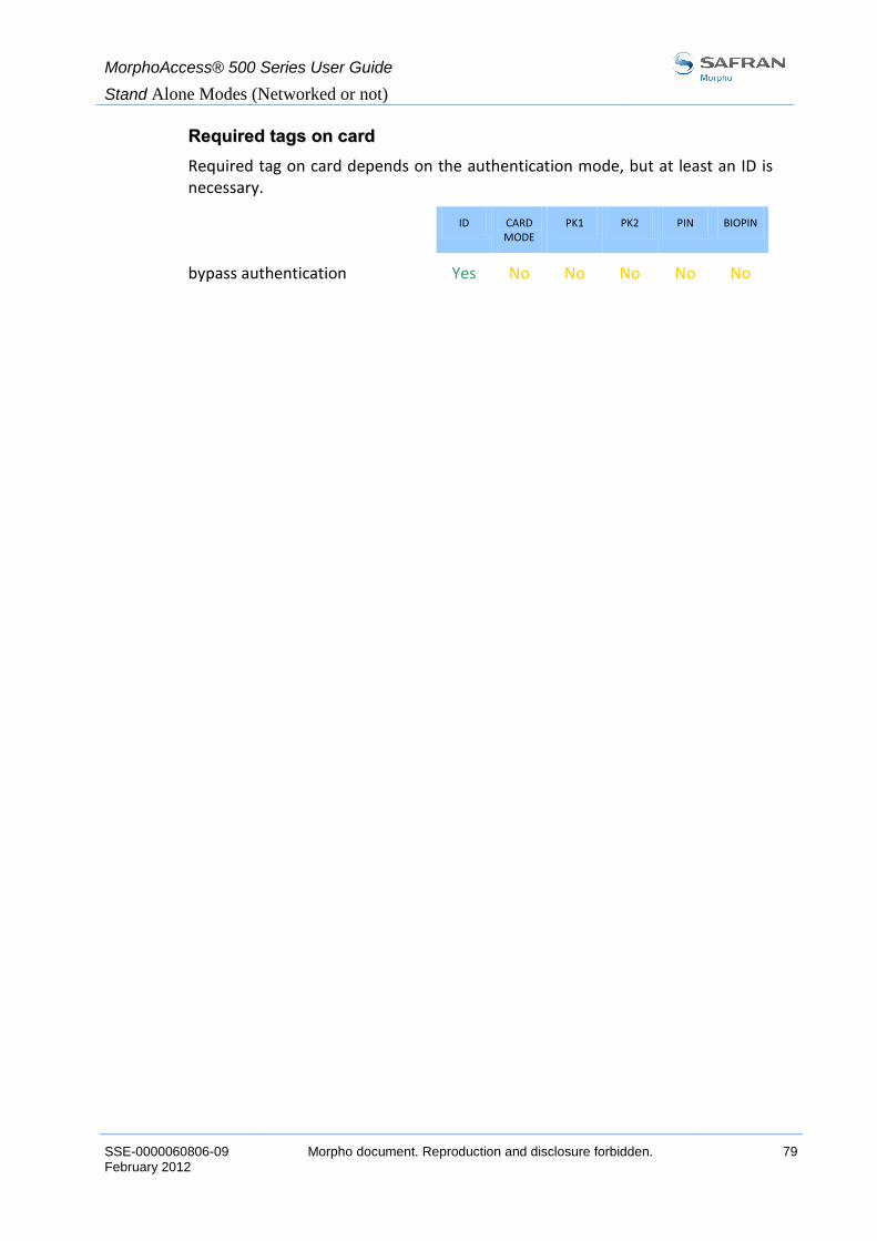
MorphoAccess® 500 Series User Guide
Stand Alone Modes (Networked or not)
SSE-0000060806-09 Morpho document. Reproduction and disclosure forbidden. 79 February 2012
RReeqquuiirreedd ttaaggss oonn ccaarrdd
Required tag on card depends on the authentication mode, but at least an ID is necessary.
ID CARD MODE
PK1 PK2 PIN BIOPIN
bypass authentication Yes No No No No No

MorphoAccess® 500 Series User Guide
Stand Alone Modes (Networked or not)
80 Morpho document. Reproduction and disclosure forbidden SSE-0000060806-09 February 2012
AAuutthheennttiiccaattiioonn wwiitthh llooccaall ddaattaabbaassee:: IIDD eenntteerreedd ffrroomm kkeeyybbooaarrdd
Biometric authentication with ID entered from keyboard
app/bio ctrl/authent ID keyboard 1 (Enabled)
In this mode, the ID of the user is entered using the MorphoAccess® keyboard. If the ID exists in the database (or in one of the five databases), the MorphoAccess® performs an authentication using the biometric templates associated to this ID.
ID entered using the keypad and the authentication starts
Figure 12: Authentication – User Id entered with the keyboard
The default screen invites the user to enter his numerical identifier.
Please enter ID
3563_
VAL COR
NOTE: ID length is limited to 24 characters.
Key deletes the last character.
Once the ID is entered, the user confirms with green key .

MorphoAccess® 500 Series User Guide
Stand Alone Modes (Networked or not)
SSE-0000060806-09 Morpho document. Reproduction and disclosure forbidden. 81 February 2012
If the corresponding ID exists in the terminal database, the user is invited to place his finger for biometric authentication.
Place your finger For Authentication
Please
If the authentication is successful, the terminal triggers the access or returns the corresponding ID to the Central Security Controller.
If the identifier is not present in the local database, authentication is not launched.
User not found in current database
35639
Once the user identification is done, the MorphoAccess® automatically loops back and waits for a new ID.
RReemmaarrkk aabboouutt MMoorrpphhooAAcccceessss®® wwiitthh MMAA--XXtteennddeedd lliicceennccee llooaaddeedd
A MorphoAccess® with MA-Xtended licence loaded will scan the five biometric databases to find the biometric templates associated to the ID.
NNoottee aabboouutt ““bbyyppaassss”” ooppttiioonn
When the bypass authentication configuration key is activated (see Bypassing the biometric control in authentication), the MorphoAccess® checks that the ID is present in the local database (or databases for MA-Xtended licence) before granting the access.

MorphoAccess® 500 Series User Guide
Stand Alone Modes (Networked or not)
82 Morpho document. Reproduction and disclosure forbidden SSE-0000060806-09 February 2012
AAuutthheennttiiccaattiioonn wwiitthh llooccaall ddaattaabbaassee:: IIDD iinnppuutt ffrroomm WWiieeggaanndd oorr
DDaattaaCClloocckk
Biometric authentication: ID input from Wiegand or Dataclock
app/bio ctrl/authent remote ID source 1 for Wiegand
2 for Dataclock
This mode requires an external card reader that will send the user’s ID to authenticate to the MorphoAccess® Wiegand or Dataclock input.
Figure 13: Authentication – User Id received in a Wiegand/DataClock frame
The default screen invites the user to pass his badge so the external reader sends the user ID to the MorphoAccess® Wiegand or Dataclock input.
Pass your badge For Authentication
Please
If the ID exists in the database, the MorphoAccess® performs an authentication using the biometric templates associated to this ID.
Place your finger For Authentication
Please
If the authentication is successful, the terminal triggers the access or returns the user ID to the Central Security Controller.
Wiegand or Dataclock input

MorphoAccess® 500 Series User Guide
Stand Alone Modes (Networked or not)
SSE-0000060806-09 Morpho document. Reproduction and disclosure forbidden. 83 February 2012
Once the user authentication is done, the MorphoAccess® automatically loops back and waits for a new input ID.
If the identifier sent by the reader is not present in the local database, authentication is not launched.
User not found in current database
64235
RReemmaarrkk aabboouutt MMoorrpphhooAAcccceessss®® wwiitthh MMAA--XXtteennddeedd lliicceennccee llooaaddeedd
A MorphoAccess® with MA-Xtended licence loaded will scan the five biometric databases to find the biometric templates associated to the ID.
NNoottee aabboouutt ““bbyyppaassss”” ooppttiioonn
When the bypass authentication configuration key is activated (see Bypassing the biometric control in authentication), the MorphoAccess® checks that the ID sent to the Wiegand or Dataclock input is present in the local database (or databases) before granting the access.
WWiieeggaanndd ffrraammee ccoonnffiigguurraattiioonn
When set up to communicate with Wiegand protocol, the MorphoAccess® can handle multiple data format.
Default format is 26 bits.
The Wiegand frame format is defined using six configuration keys. A different protocol can be defined for input.
Wiegand frame timings are not customizable. Additional security (ciphering) is not handled. All Wiegand protocols are reverse.
Here after are listed the customizable parameters of a Wiegand frame.
- Length
A Wiegand frame can contain up to 128 bits.
- Control bits
In a Wiegand frame, start and stop bits are used as control bits. They can be fixed to 0 or 1 or be used as parity (odd or even) bits calculated over bits of the frame.
- Data
In the Wiegand protocol, three data are handled: the Site code (also called Facility Code or Comparison Number), the ID (also called Badge Number or Sequence Number) and a custom data. Data can have a variable bit size and can be located anywhere in the frame. Data are inserted in the frame MSB first.

MorphoAccess® 500 Series User Guide
Stand Alone Modes (Networked or not)
84 Morpho document. Reproduction and disclosure forbidden SSE-0000060806-09 February 2012
NOTE: Since the software version 2.00 configuration key name has been modified. The previous set key value is preserved.
Wiegand input parameters
app/wiegand in/
frame length (before v2.00: length)
1-128 Defines the number of bits of the frame.
start format (before v2.00: start)
0.0 1.0 2.n 3.n 4.0
Defines the start control bit: Reset to 0. Set to 1. Even parity calculated over the n first bits. Odd parity calculated over the n first bits. No start bit.
stop format (before v2.00: stop)
0.0 1.0 2.n 3.n 4.0
Defines the stop control bit: Reset to 0. Set to 1. Even parity calculated over the n last bits. Odd parity calculated over the n last bits. No stop bit.
site format (before v2.00: site)
n.m Insert m bits of site value at offset n.
ID format (before v2.00: ID)
n.m Insert m bits of ID value at offset n.
custom format (before v2.00: custom)
n.m RFU.
WWiieeggaanndd ffrraammee eexxaammppllee ((2266 bbiittss))
0 1 2 3 … 8 9 10 11 12 … 23 24 25
START SITE ID STOP
1 8 bits 16 bits 1
START bit calculation range STOP bit calculation range

MorphoAccess® 500 Series User Guide
Stand Alone Modes (Networked or not)
SSE-0000060806-09 Morpho document. Reproduction and disclosure forbidden. 85 February 2012
BByyppaassssiinngg tthhee bbiioommeettrriicc ccoonnttrrooll iinn aauutthheennttiiccaattiioonn
This mode requires only a user ID. This ID can be read on a smartcard, entered on the keyboard or received on the Wiegand or Dataclock input.
The bypass authentication configuration key must be combined with an authentication mode. Activating this flag means that the biometric verification is bypassed.
TThhee tteerrmmiinnaall ccoonnttrroollss tthhaatt tthhee uusseerr IIDD eexxiissttss iinn tthhee ddaattaabbaassee
When combined with an authentication mode with templates in local database, the MorphoAccess® verifies that the ID is present in the local database before granting the access.
ID on a contactless card
Disabling biometric control, but ID must be present in the local database
app/bio ctrl/bypass authentication 1 (Enabled)
app/bio ctrl/authent ID contactless 1 (Enabled)
RReeqquuiirreedd ttaaggss oonn ccaarrdd
ID CARD MODE
PK1 PK2 PIN BIOPIN
bypass authentication Yes No No No No No
ID entered on the keyboard
Disabling biometric control, but ID must be present in the local database
app/bio ctrl/bypass authentication 1 (Enabled)
app/bio ctrl/authent ID keyboard 1 (Enabled)
ID sent to the Wiegand or Dataclock input
Disabling biometric control, but ID must be present in the local database
app/bio ctrl/bypass authentication 1 (Enabled)
app/bio ctrl/authent remote ID source 1 for Wiegand
2 for Dataclock
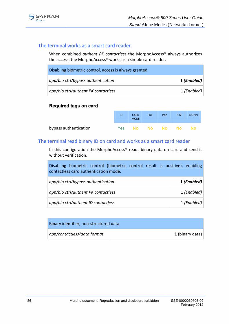
MorphoAccess® 500 Series User Guide
Stand Alone Modes (Networked or not)
86 Morpho document. Reproduction and disclosure forbidden SSE-0000060806-09 February 2012
TThhee tteerrmmiinnaall wwoorrkkss aass aa ssmmaarrtt ccaarrdd rreeaaddeerr..
When combined authent PK contactless the MorphoAccess® always authorizes the access: the MorphoAccess® works as a simple card reader.
Disabling biometric control, access is always granted
app/bio ctrl/bypass authentication 1 (Enabled)
app/bio ctrl/authent PK contactless 1 (Enabled)
RReeqquuiirreedd ttaaggss oonn ccaarrdd
ID CARD MODE
PK1 PK2 PIN BIOPIN
bypass authentication Yes No No No No No
TThhee tteerrmmiinnaall rreeaadd bbiinnaarryy IIDD oonn ccaarrdd aanndd wwoorrkkss aass aa ssmmaarrtt ccaarrdd rreeaaddeerr
In this configuration the MorphoAccess® reads binary data on card and send it without verification.
Disabling biometric control (biometric control result is positive), enabling contactless card authentication mode.
app/bio ctrl/bypass authentication 1 (Enabled)
app/bio ctrl/authent PK contactless 1 (Enabled)
app/bio ctrl/authent ID contactless 1 (Enabled)
Binary identifier, non-structured data
app/contactless/data format 1 (binary data)
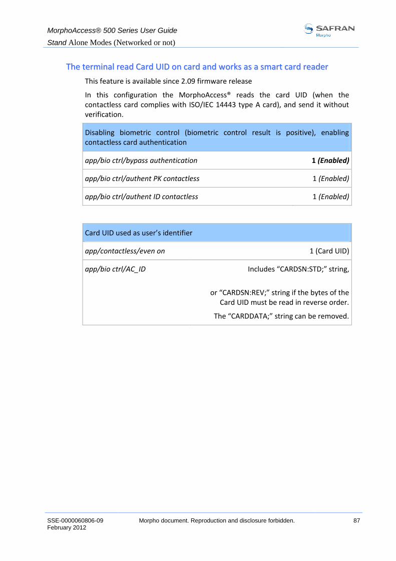
MorphoAccess® 500 Series User Guide
Stand Alone Modes (Networked or not)
SSE-0000060806-09 Morpho document. Reproduction and disclosure forbidden. 87 February 2012
TThhee tteerrmmiinnaall rreeaadd CCaarrdd UUIIDD oonn ccaarrdd aanndd wwoorrkkss aass aa ssmmaarrtt ccaarrdd rreeaaddeerr
This feature is available since 2.09 firmware release
In this configuration the MorphoAccess® reads the card UID (when the contactless card complies with ISO/IEC 14443 type A card), and send it without verification.
Disabling biometric control (biometric control result is positive), enabling contactless card authentication
app/bio ctrl/bypass authentication 1 (Enabled)
app/bio ctrl/authent PK contactless 1 (Enabled)
app/bio ctrl/authent ID contactless 1 (Enabled)
Card UID used as user’s identifier
app/contactless/even on 1 (Card UID)
app/bio ctrl/AC_ID Includes “CARDSN:STD;” string,
or “CARDSN:REV;” string if the bytes of the
Card UID must be read in reverse order.
The “CARDDATA;” string can be removed.

MorphoAccess® 500 Series User Guide
Stand Alone Modes (Networked or not)
88 Morpho document. Reproduction and disclosure forbidden SSE-0000060806-09 February 2012
RReeccooggnniittiioonn mmooddee ssyynntthheessiiss
The MorphoAccess® operating mode is driven by:
the authentication or identification mode required: Card Only, Card + Biometric, Biometric only,
what defines the operating mode: Card or Terminal.
Mode defined by Card
app/bio ctrl/authent card mode
1
Mode defined by Terminal
app/bio ctrl/authent card mode
0
Operating mode
Authentication
Card only
ID in card
Card Mode Tag = ID_ONLY
ID in card
bypass authentication 1
authent ID contactless 1
Check ID on terminal
ID in card
bypass authentication 1
authent PK contactless 1
No ID check on terminal
Authentication
Card
+ Biometric
ID and BIO in Card
Card Mode Tag = PKS
ID and BIO in card
bypass authentication 0
authent PK contactless 1
ID on card and BIO in terminal
bypass authentication 0
authent ID contactless 1
Identification
Biometric only
ID and BIO in terminal
identification 1

MorphoAccess® 500 Series User Guide
Stand Alone Modes (Networked or not)
SSE-0000060806-09 Morpho document. Reproduction and disclosure forbidden. 89 February 2012
SSeettttiinngg uupp rreeccooggnniittiioonn ssttrraatteeggyy
TTwwoo aatttteemmppttss mmooddee
If the recognition fails, it is possible to give a “second chance” to the user.
In identification mode, if a bad finger is presented, the user has 5 seconds to present a finger again. The result is sent if this period expires or if the user presents a finger again.
In authentication mode, if the user presents a bad finger, he can replace his finger without presenting his card again. The result is sent only after this second attempt.
It is possible to set the finger presentation timeout and to deactivate this “two attempts mode”.
If the user is not identified, a second step follows immediately using a smarter coding method. This coding allows recognizing users with dry fingers or fingers with a bad placement on the sensor. However this coding is slower than the light one.
PPaarraammeetteerrss
This mode can be configured using the Morpho Bio Toolbox for example.
By default, the two attempts mode is activated.
Setting up the number of attempts
app/bio ctrl/nb attempts 1 (only one attempts)
2 (two attempts mode)
The period between two attempts in identification (two attempts mode) can be modified.
Setting up the identification timeout
app/bio ctrl/identification timeout 5 (1-60)
In authentication mode a finger presentation period can be defined.
Setting up the authentication timeout
app/bio ctrl/authent timeout 10 (1-60)

MorphoAccess® 500 Series User Guide
Stand Alone Modes (Networked or not)
90 Morpho document. Reproduction and disclosure forbidden SSE-0000060806-09 February 2012
SSeettttiinngg uupp mmaattcchhiinngg ppaarraammeetteerrss
Setting up matching threshold
bio/bio ctrl/matching th 3 (1-10)
The performances of a biometric system are characterized by two quantities, the False Non Match Rate - FNMR - (also called False Reject Rate) and the False Match Rate - FMR - (also called False Acceptance Rate). Different trade-offs are possible between FNMR and FMR depending on the security level targeted by the Central Security Controller. When convenience is the most important factor, the FNMR must be low and conversely if security is more important then the FMR has to be minimized.
Different tunings are proposed in the MorphoAccess® depending on the security level targeted by the system. The table below details the different possibilities.
This parameter can be set to values from 1 to 10. This parameter specifies how tight the matching threshold is. Threshold scoring values are identified hereafter:
1 Very few persons rejected FMR < 1%
2 FMR < 0.3%
3 Recommended value FMR < 0.1%
4 FMR < 0.03%
5 Intermediate threshold FMR < 0.01%
6 FMR < 0.001%
7 FMR < 0.0001%
8 FMR < 0.00001%
9 Very high threshold (few false acceptances). Secure application
FMR < 0.0000001%
10 High threshold for test purpose only
There are very little false recognition, and many rejections.

MorphoAccess® 500 Series User Guide
Stand Alone Modes (Networked or not)
SSE-0000060806-09 Morpho document. Reproduction and disclosure forbidden. 91 February 2012
FFaakkee ffiinnggeerr ddeetteeccttiioonn ((OOPPTTIIOONN))
CCoommppaattiibbiilliittyy wwiitthh MMoorrpphhooAAcccceessss®® 220000 aanndd 330000 SSeerriieess eeqquuiippppeedd wwiitthh ffaakkee
ffiinnggeerr ddeetteeccttiioonn
- Delay after fake finger detection The function associated to MorphoAccess®.200 and 300 Series /cfg/Maccess/Security Policy/Delay in 10ms configuration key is no more supported.
- FFD security level The function associated to app/bio ctrl/FFD security level is only for stand-alone mode. (On MorphoAccess®.200 and 300 Series, this parameter applied to standalone mode and ILV) ILV has to set this parameter to have a security level different from default security level.
FFFFDD sseeccuurriittyy lleevveell
The fake finger detection is characterized by a false reject rate (percentage of live fingers detected as fake fingers) and a false acceptance rate (percentage of fake finger detected as real ones). This FRR (resp. FAR) is called FFD-FRR (resp. FFD-FAR). The overall reject rate of MorphoAccess® equipped with fake finger detection is in fact: standard MA FRR + FFD-FRR.
Three security levels are proposed and provide different trade-off between FFD-FAR and FFD-FRR.
0 Low fake finger detection security level
1 (default) Medium fake finger detection security level
2 High fake finger detection security level
Setting up FFD security level
bio/bio ctrl/FFD security level 1 (0-2)
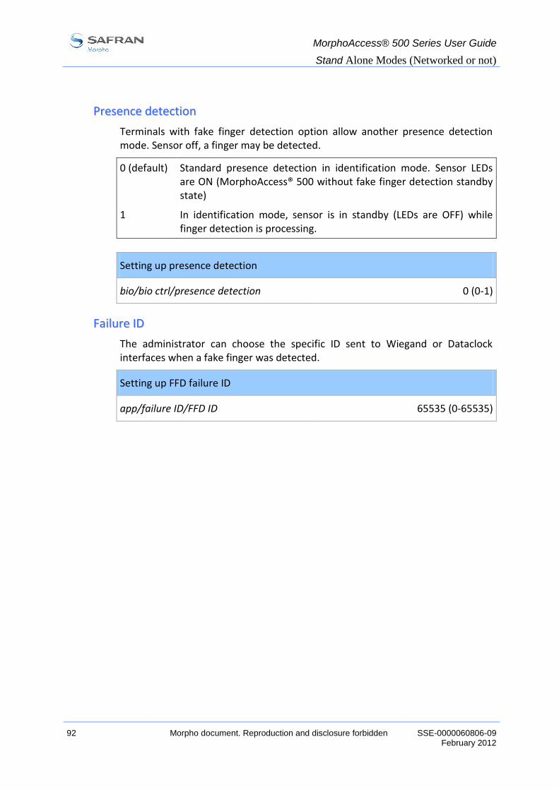
MorphoAccess® 500 Series User Guide
Stand Alone Modes (Networked or not)
92 Morpho document. Reproduction and disclosure forbidden SSE-0000060806-09 February 2012
PPrreesseennccee ddeetteeccttiioonn
Terminals with fake finger detection option allow another presence detection mode. Sensor off, a finger may be detected.
0 (default) Standard presence detection in identification mode. Sensor LEDs are ON (MorphoAccess® 500 without fake finger detection standby state)
1 In identification mode, sensor is in standby (LEDs are OFF) while finger detection is processing.
Setting up presence detection
bio/bio ctrl/presence detection 0 (0-1)
FFaaiilluurree IIDD
The administrator can choose the specific ID sent to Wiegand or Dataclock interfaces when a fake finger was detected.
Setting up FFD failure ID
app/failure ID/FFD ID 65535 (0-65535)

MorphoAccess® 500 Series User Guide
IDLE mode
SSE-0000060806-09 Morpho document. Reproduction and disclosure forbidden. 93 February 2012
IIDDLLEE mmooddee

MorphoAccess® 500 Series User Guide
IDLE mode
94 Morpho document. Reproduction and disclosure forbidden SSE-0000060806-09 February 2012
IIddllee mmooddee pprreesseennttaattiioonn
This feature is available since 2.09 firmware revision.
When using this mode, some features are temporary deactivated after a certain period of inactivity, so that the MorphoAccess® does not draw attention the night or consumes less.
For the moment, only the following features can be deactivated by the idle mode:
LCD and keyboard backlight,
Biometric sensor.
Those features can be activated again by using the remaining activated features such as pressing the keyboard, receiving a distant command, and so on.
It means, if only the backlight is deactivated, it can also be turned on by putting a finger on the biometric sensor or by presenting a contactless card in the antenna field.
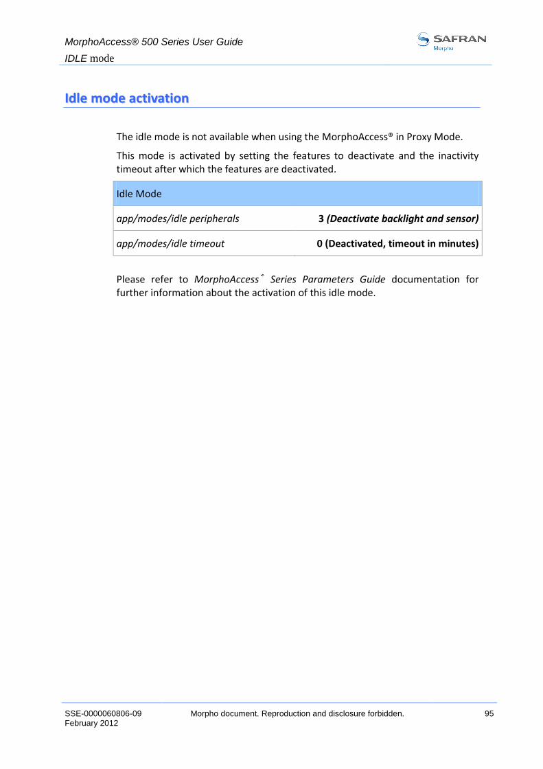
MorphoAccess® 500 Series User Guide
IDLE mode
SSE-0000060806-09 Morpho document. Reproduction and disclosure forbidden. 95 February 2012
IIddllee mmooddee aaccttiivvaattiioonn
The idle mode is not available when using the MorphoAccess® in Proxy Mode.
This mode is activated by setting the features to deactivate and the inactivity timeout after which the features are deactivated.
Idle Mode
app/modes/idle peripherals 3 (Deactivate backlight and sensor)
app/modes/idle timeout 0 (Deactivated, timeout in minutes)
Please refer to MorphoAccess® Series Parameters Guide documentation for further information about the activation of this idle mode.

MorphoAccess® 500 Series User Guide
Proxy mode
96 Morpho document. Reproduction and disclosure forbidden SSE-0000060806-09 February 2012
PPrrooxxyy mmooddee
Proxy mode is an operating mode where the Host System performs the access control remotely.

MorphoAccess® 500 Series User Guide
Proxy mode
SSE-0000060806-09 Morpho document. Reproduction and disclosure forbidden. 97 February 2012
PPrrooxxyy mmooddee ((oorr ssllaavvee)) pprreesseennttaattiioonn
This operating mode allows to control the MorphoAccess® remotely (the link is IP or RS422) using a set of biometric and databases management commands.
In Proxy mode the access control is performed remotely by the Host System: the MorphoAccess® works as a slave waiting for external commands such as:
user identification,
user verification,
relay activation,
read data on a contactless smart card,
Biometric database management,
terminal configuration changes,
read an entry from the keyboard,
display a message,
read a contactless smart card.
Figure 14: Proxy mode
Please refer to MorphoAccess® Host System Interface Specification: this document explains how to remotely manage a terminal.
For further details about SSL on the MorphoAccess®, please refer to the SSL Solution for MorphoAccess® documentation.

MorphoAccess® 500 Series User Guide
Proxy mode
98 Morpho document. Reproduction and disclosure forbidden SSE-0000060806-09 February 2012
PPrrooxxyy mmooddee aaccttiivvaattiioonn
Identification and authentication must be disabled. It means that all controls must be turned off: the terminal becomes a slave.
Proxy mode
app/bio ctrl/identification 0 (Disabled)
app/bio ctrl/authent card mode 0 (Disabled)
app/bio ctrl/authent PK contactless 0 (Disabled)
app/bio ctrl/authent ID contactless 0 (Disabled)
app/bio ctrl/authent ID keyboard 0 (Disabled)
app/bio ctrl/authent remote ID source 0 (None)
app/bio ctrl/control PIN 0 (No)
app/bio ctrl/bypass authentication 0 (Disabled)

MorphoAccess® 500 Series User Guide
Terminal Customization
SSE-0000060806-09 Morpho document. Reproduction and disclosure forbidden. 99 February 2012
TTeerrmmiinnaall CCuussttoommiizzaattiioonn

MorphoAccess® 500 Series User Guide
Terminal Customization
100 Morpho document. Reproduction and disclosure forbidden SSE-0000060806-09 February 2012
SSeettttiinngg UUpp TTiimmee MMaasskk
When using MEMS™, a time mask feature is available. This mode enables the access according to its time mask. Time mask is defined by slots of 15 minutes over a week.
NOTE: Since software version 2.00 the configuration key path has been modified. The previous set key value is preserved.
Time mask activation
app/modes/time mask
Before v2.00: app/time mask/enabled
1 (Enabled)
To use this feature the local database must have been created with a specific additional field. If this field does not exist activating this feature will forbid the access to every user.
Please refer to MorphoAccess® Host Interface Specification to understand how to create a database with time mask feature.

MorphoAccess® 500 Series User Guide
Terminal Customization
SSE-0000060806-09 Morpho document. Reproduction and disclosure forbidden. 101 February 2012
MMuullttiilliinngguuaall aapppplliiccaattiioonn
The MorphoAccess® can display texts in several languages. It is possible to download a user defined language table. For more information about this feature, refer to the MorphoAccess® Host System Interface Specifications.
Default language
app/G.U.I/default language 0 English (default)
1 Spanish
2 French
3 German
4 Italian
5 Portuguese
6 Arabic
7 Turkish

MorphoAccess® 500 Series User Guide
Terminal Customization
102 Morpho document. Reproduction and disclosure forbidden SSE-0000060806-09 February 2012
DDiissppllaayy hhoouurr
It is possible to display date and hour on terminal screen.
Display hour
app/G.U.I./display hour 1
Place your finger for Identification
Please
4 14:25 DEC 10

MorphoAccess® 500 Series User Guide
Access control Result exportation
SSE-0000060806-09 Morpho document. Reproduction and disclosure forbidden. 103 February 2012
AAcccceessss ccoonnttrrooll RReessuulltt eexxppoorrttaattiioonn
The MorphoAccess® can export the result of the control to a Central Security Controller, and can log the result in a local diary or directly command an access.
This section is only an introduction about the MorphoAccess® interfaces. Please refer to MorphoAccess® Remote Messages Specification for complete details of each interface.

MorphoAccess® 500 Series User Guide
Access control Result exportation
104 Morpho document. Reproduction and disclosure forbidden SSE-0000060806-09 February 2012
RReemmoottee mmeessssaaggeess:: sseennddiinngg tthhee IIDD ttoo tthhee CCeennttrraall SSeeccuurriittyy CCoonnttrroolllleerr
PPrreesseennttaattiioonn
The MorphoAccess® can send status messages in real time to a Central Security Controller by different means and through different protocols. This information, called Remote Messages, can be used for instance to display on an external screen the result of a biometric operation, the name or the ID of the person identified… depending on the role of the controller in the system.
Figure 15: Send access control result message
The MorphoAccess® Remote Messages Specification describes the different solutions offered by the MorphoAccess® to dialog with a controller, and how to make use of them.
SSuuppppoorrtteedd PPrroottooccoollss
The terminal can send messages about the biometric operations performed by the MorphoAccess® to a controller through the following protocols:
Wiegand,
Dataclock,
RS485/422,
IP (TCP or UDP or SSL).
For further information about the SSL on MorphoAccess®, please refer to SSL Solution for the MorphoAccess® documentation.
IP
RS485/422
Wiegand/Dataclock

MorphoAccess® 500 Series User Guide
Access control Result exportation
SSE-0000060806-09 Morpho document. Reproduction and disclosure forbidden. 105 February 2012
RReellaayy aaccttiivvaattiioonn
If the control is successful, a relay may be activated to directly control a door.
Relay activation
app/relay/enabled 1 (Enabled)
The relay aperture time can be defined and is set by default to 3 seconds (i.e. 300).
Relay aperture time in 10 ms
app/relay/aperture time in 10 ms 300
(50 to 60000)
The default state of the relay can also be defined. By default, the relay is opened when it is in idle state.
Relay default state
app/relay/relay default state 0 (Opened)
1 (Closed)
Access control installation using a relay offers a low security level.

MorphoAccess® 500 Series User Guide
Access control Result exportation
106 Morpho document. Reproduction and disclosure forbidden SSE-0000060806-09 February 2012
RReellaayy eexxtteerrnnaall aaccttiivvaattiioonn
This feature is available since 2.07 firmware revision.
MorphoAccess® relay is controlled by LED1 input
app/relay/external control by LED1 1 (Enabled)
This function controls the relay with a push-button connected to LED1 input. It means either a successful recognition or a signal on LED1 will activate the relay.
If LED1 is high impedance (push-button off) the relay is not activated.
If LED1 is connected to GND (push-button on) the relay is activated.
Figure 16: Relay external activation
Typically the MorphoAccess® relay controls the door.
To enter in the building the user must be successfully recognized by the MorphoAccess®.
A simple push-button connected to LED1 on the MorphoAccess® will trigger the door to leave the building.

MorphoAccess® 500 Series User Guide
Access control Result exportation
SSE-0000060806-09 Morpho document. Reproduction and disclosure forbidden. 107 February 2012
LLoogg ffiillee
Enabling recording of all access request results in an internal log file
app/log file/enabled 1 (Enabled)
When this feature is enabled, the MorphoAccess® creates a dated record for each access request when the result is known, in an internal log file. The created record includes:
the date and the time of record creation,
the result of the access control (granted or denied, and if denied for which reason),
the identifier of the user (if available),
the selected time and attendance function (if applicable).
The MorphoAccess® 500 Series terminals can record up to 65000 dated records.
It is possible to download the log file. For more information about this feature, refer to the MorphoAccess® Host System Interface Specification.
It is also possible to display the content of the log file using the Logs Viewer Application.
JANUARY 8 2007
15:25,OK,783170
15:28,KO,
15:45,OK,7895641
15:59,KO,783170
Enabling specific actions when internal log file is full
app/log file/full handling “00000000” (no specific action)
Depending on the configuration, when the log file limit has been reached, the MorphoAccess® 500 Series terminal can:
Send an information message to a distant host (cf. Messages sending)
Display a message on the screen
Reset the log file.
Please refer to MorphoAccess® Parameters Guide for further details.

MorphoAccess® 500 Series User Guide
Access control Result exportation
108 Morpho document. Reproduction and disclosure forbidden SSE-0000060806-09 February 2012
LLEEDD IINN ffeeaattuurree
DDeessccrriippttiioonn
When this feature is activated, the terminal waits also for a confirmation from a distant system (i.e. a central access controller) before granting the access to the user.
When no answer is received, the access is denied, even if the local access rights control is positive.
This feature is to be use in addition to the Sending the access control result to a distant system function.
Figure 17: LED IN feature
For more information about this interface, please refer to MorphoAccess® VP Series Installation Guide.
PPrroocceessss
1. If the user is recognized, then the MorphoAccess® terminal sends a message
with the user’s identifier, to a distant system (such as a central access
controller).
2. Then the MorphoAccess® terminal starts waiting, during an adjustable
duration, for a contact closure between LED1 and GND wires, or between
LED2 and GND wires.
3. When the controller receives the message (step 1), it performs its own access
control rights checks.
4. According to the result of this check, the access controller closes the contact
connected to LED1 and GND wires to grant the access, or close the contact
connected to LED2 and GND wires to deny the access. If timeout occurs,
while waiting for a low level on LED1 or on LED2 wire, the access is also
denied.

MorphoAccess® 500 Series User Guide
Access control Result exportation
SSE-0000060806-09 Morpho document. Reproduction and disclosure forbidden. 109 February 2012
5. The MorphoAccess® terminal indicates then the final result of the access
control request to the user, and returns to the “wait for access request” state as
soon as the LED1 and LED2 wires return in its default state (high level).
TThhee ccoonnttrroolllleerr ssuuppppoorrttss nneeiitthheerr LLEEDD11 nnoorr LLEEDD22 ssiiggnnaallss
When the access controller has no relay contact to provide an answer to the MorphoAccess® terminal, then the decision to emit either the “access granted” signal or the “access denied” signal is taken by another way. It is either the MorphoAccess® terminal itself that decide, or it waits for the access controller answer through the local area network (TCP), or on the serial port in (RS422).
It is strongly recommended to disable the LED IN feature, to avoid any interference on MorphoAccess terminal behavior.
TThhee ccoonnttrroolllleerr ssuuppppoorrttss oonnllyy LLEEDD11 ssiiggnnaall
When the access controller has only one relay contact which is dedicated to the “access granted” answer, this one must be connected between the LED1 and GND wires. The LED1 wire is set to the low level by closing the contact between the LED1 and the GND wires), and it means “access granted".
The MorphoAccess® terminal uses the timeout of the wait for a low level on the on LED1 wire or LED2 wire as "access denied” answer.
To minimize at most the waiting time of the user, the MorphoAccess® terminal timeout value, must be adjusted to a value a little bit higher than the maximal value of the controller response time.
Warning: if the LED2 wire is connected, it must be constantly maintained in the high state.
TThhee ccoonnttrroolllleerr ssuuppppoorrttss LLEEDD11 aanndd LLEEDD22 ssiiggnnaallss
When the controller supports one relay contact for each of the possible answers then:
the « access granted » contact must be connected between the LED1 and the GND wires of the terminal
the « access denied » contact must be connected between the LED2 et the GND wires of the terminal.
The MorphoAccess® terminal considers that:
The answer of the controller is "access granted", when the controller puts the LED1 wire to the low state (by closing a contact between the LED1 and the GND wires), and leaves the LED 2 wire to the high state.
The answer of the controller is "access denied", when the controller puts the LED2 wire to the low state (by closing a contact between the LED2 and the GND wires), whatever is the state of the LED 1 wire.

MorphoAccess® 500 Series User Guide
Access control Result exportation
110 Morpho document. Reproduction and disclosure forbidden SSE-0000060806-09 February 2012
The MorphoAccess® terminal also considers that the answer of the controller is "access denied" in case of time-out while expecting for a closure between LED1 and GND wires, or between LED2 and GND wires.
AAccttiivvaattiioonn kkeeyy
This feature is enabled (and disabled) by only one configuration key.
LED IN feature activation
app/led IN/enabled = 0 Disabled (default value)
app/led IN/enabled =1 Enabled
CCoonnffiigguurraattiioonn kkeeyy
The maximum duration during which the terminal has to wait for an answer from the distant system, is adjustable by one configuration key. The answer from the distant system (i.e. the access controller), is either a low level on LED1 wire or a low level on the LED2 wire.
LED IN acknowledge timeout value, in number of 10 ms units
app/led IN/controller ack timeout 300 (0 to 268435455)

MorphoAccess® 500 Series User Guide
Security Features
SSE-0000060806-09 Morpho document. Reproduction and disclosure forbidden. 111 February 2012
SSeeccuurriittyy FFeeaattuurreess

MorphoAccess® 500 Series User Guide
Security Features
112 Morpho document. Reproduction and disclosure forbidden SSE-0000060806-09 February 2012
SSeeccuurriittyy SSwwiittcchh MMaannaaggeemmeenntt
AAllaarrmm aaccttiivvaattiioonn
The MorphoAccess® can detect two intrusion attempt types:
someone tries to steal the complete terminal (anti theft opto-sensor is triggered),
someone tries to open the terminal (tamper switch is triggered).
The MorphoAccess® can transmit an alarm indication to the central controller in case of intrusions. For that purpose, contact connections are provided on I/O board (open circuit equals detection).
The MorphoAccess® can send an alarm message to the central controller in case of intrusions. It can also play a sound alarm while sending the alarm.
NOTE: Either the tamper switch or the opto-sensor triggers the alarm message. Please refer to MorphoAccess® 500 Series Installation Guide to identify these switches on the terminal.
Figure 18: Security Switch management
To send an alarm on an output (IP, RS485/RS422, Wiegand, Dataclock), the corresponding interface must be activated otherwise no alarm will be sent.
Because Wiegand and Dataclock are multiplexed on the same lines, only one of these protocols shall be enabled at one time, else priority is given to Wiegand, then Dataclock.
Those keys are:
app/send ID wiegand/enabled,
app/send ID dataclock/enabled,
app/send ID serial/enabled,
Alarm message
IP (UDP, TCP, SSL)
RS485/RS422
Wiegand
DataClock

MorphoAccess® 500 Series User Guide
Security Features
SSE-0000060806-09 Morpho document. Reproduction and disclosure forbidden. 113 February 2012
app/send ID serial/mode (to select RS422 or RS485 link),
app/send ID UDP/enabled,
app/send ID ethernet/mode (to choose between UDP or TCP),
app/send ID ethernet/SSL enabled (Please refer to SSL Solution for MorphoAccess® documentation).
Setting the key app/tamper alarm/level to an appropriate value configure security switch management feature.
Tamper Alarm Level
app/tamper alarm/level
0 No Alarm.
1 Send Alarm (No Sound Alarm).
2 Send Alarm and Activates Buzzer (Sound Alarm)
0 (0 – 2)
The key app/failure ID/alarm ID defines the value of the alarm ID to send to Wiegand or Dataclock. This ID permits to distinguish between a user ID and an error ID. To be validated, key app/failure ID/enabled must be set to 1.
Tamper Alarm ID
app/failure ID/alarm ID
app/failure ID/enabled
65535 (0 – 65535)
1 (Enabled)
In Wiegand and Dataclock the alarm ID is sent like other Failure Ids. See the documentation MorphoAccess® Remote Messages Specification for a description of the packet format in UDP and RS485.
EExxaammpplleess
EExxaammppllee 11:: SSeenndd aann aallaarrmm IIDD ((6622222211)) iinn WWiieeggaanndd,, aanndd ppllaayy ssoouunndd
wwaarrnniinngg,, iinn ccaassee ooff iinnttrruussiioonn ddeetteeccttiioonn..
To send an alarm in Wiegand, the key app/send ID wiegand/enabled must be set to 1, and the key app/tamper alarm/level must be set to 2 (alarm and buzzer).
The key app/failure ID/alarm ID must be set to 62221 to link the intrusion event to this identifier and the key app/failure ID/enabled must be set to 1.
EExxaammppllee 22:: SSeenndd aann aallaarrmm iinn UUDDPP qquuiieettllyy iinn ccaassee ooff iinnttrruussiioonn
ddeetteeccttiioonn..
To send an alarm in UDP, the key app/send ID UDP/enabled must be set to 1.
Then the key app/tamper alarm/level must be set to 1 (quiet alarm.)

MorphoAccess® 500 Series User Guide
Security Features
114 Morpho document. Reproduction and disclosure forbidden SSE-0000060806-09 February 2012
PPaasssswwoorrddss
Two passwords protect the system:
the Terminal Configuration Password protects the MorphoAccess® local administration and controls devices settings,
the User Management Password is required to access to local database: it protects the Enrolment Application and the Log Viewer Application.
Both default passwords values are “12345”.
If a password is forgotten, contact the hotline. Then it is strongly recommended to put the new password in a safe place.
MorphoAccess® 500 Series User Guide
Messages sending
SSE-0000060806-09 Morpho document. Reproduction and disclosure forbidden. 115 February 2012
MMeessssaaggeess sseennddiinngg
This section describes how the MorphoAccess® 500 Series terminal can send messages to another entity. Those messages are different than the result exportation (cf. Result exportation).

MorphoAccess® 500 Series User Guide
Messages sending
116 Morpho document. Reproduction and disclosure forbidden SSE-0000060806-09 February 2012
PPrriinncciippllee
When specific events occurred during the MorphoAccess® access control application’s working, some messages can be generated and sent to another physical entity.
The events that produce messages sending are:
Internal log file full
Internal database synchronization request
Please refer to MorphoAccess® Remote Messages Specification for details about the messages content.

MorphoAccess® 500 Series User Guide
Messages sending
SSE-0000060806-09 Morpho document. Reproduction and disclosure forbidden. 117 February 2012
EEvveennttss
The messages sending process is customizable using two configuration files:
Events.cfg
Remotemsg.cfg
This section only details the events.cfg file.
The terminal allows choosing which event generates a message to send. By default, every event generates a message.
Events mask
Events/general/active “FFFFFFFF”
(Every events generate messages)
For each event, the number of identical messages sent can be configured:
Log Full number of sending
Events/log_full/nb sending 0
(No sending attempt)
For each messages to send, the following parameters are customizable:
Number of retry for the current message,
Time to wait between two attempts,
Response awaited or not,
Terminal sending interface (cf. Sending Interfaces).
Please refer to MorphoAccess® Parameters Guide for further details about the messages sending configuration.

MorphoAccess® 500 Series User Guide
Messages sending
118 Morpho document. Reproduction and disclosure forbidden SSE-0000060806-09 February 2012
SSeennddiinngg IInntteerrffaacceess
This section only details the remotemsg.cfg file.
The terminal allows choosing the number of interfaces that will be available for the messages sending process (cf. Events).
By default, no interface is available.
Number of available interfaces
Remotemsg/interface/nb interfaces 0
For each interface available, the following parameters are customizable:
Communication layer
Protocol used
Parameters depending on the layer and the protocol used.
There is only the TCP protocol on the IP layer that is available. In that case, the parameters available are:
The distant IP address to contact
The distant port to connect to
The sending timeout
The receiving timeout
Please refer to MorphoAccess® Parameters Guide for further details about the interfaces configuration.

MorphoAccess® 500 Series User Guide
Appendix
SSE-0000060806-09 Morpho document. Reproduction and disclosure forbidden. 119 February 2012
AAppppeennddiixx

MorphoAccess® 500 Series User Guide
Appendix
120 Morpho document. Reproduction and disclosure forbidden SSE-0000060806-09 February 2012
EEnnrroollmmeenntt oonn tteerrmmiinnaall wwiitthh ssyynncchhrroonniizzaattiioonn
PPrriinncciippllee
Depending on its configuration, the MorphoAccess® terminal can log in a file every actions performed on the biometric database (or databases) using the dedicated enrolment application.
Then the database administrator can synchronize other MorphoAccess® with this database, but keeping the reference database on a host system (using MEMS™ for example).
On the administrator demand, the terminal sends a synchronization message to the host system (cf. Messages sending).
The host system asks for the changes by asking for the log lines and then updates its reference database by asking for the new users data for example.
Finally, the host system downloads the updated database in every MorphoAccess® and erases the log file.
Note: The log file containing the biometric changes is not the access control result log file.
Example with MEMS™ application:
Local administrator adds/modifies/deletes users or encodes contactless smartcards, generating corresponding Local Enrolment Logs. At the end of the enrolment session, local administrator can launch synchronization. Terminal then sends a synchronization request to distant host. Distant application administrator acknowledges synchronization request. Then it asks the terminal the Local Enrolment Logs (data = ID + add/modify/delete/encode tag) Distant application administrator then asks the terminal for the database records it would like to retrieve. Terminal answers by sending corresponding records (including biometric data). Data are then updated in centralized database. Distant application can then re-dispatch consolidated database to other connected terminals.

MorphoAccess® 500 Series User Guide
Appendix
SSE-0000060806-09 Morpho document. Reproduction and disclosure forbidden. 121 February 2012
AAccttiivvaattiioonn
To activate this feature, several parameters have to be set:
The actions to log (key /log/LogParam/LogMask),
The name of the internal log file (key /log/LogParam/LogFile)
The size of the internal log file (key /log/LogParam/LogFileSize),
The events that generates messages sending (key /events/general/active),
The number of synchronization messages (key /events/bio_chg/nb sending),
The sending parameters (key /events/bio_chg/send#) cf. Events.
The sending interface (key /remotemsg/interfaces/int#) cf. Sending Interfaces.
Please refer to MorphoAccess® Parameters Guide to know about those configurations key, and to MorphoAccess® Enrolment Application User Guide to know about the logged actions.
Once the terminal is configured, the “synchronize” item can be selected in the dedicated enrolment application.
SSttooppppiinngg
The synchronization cannot be cancelled. The process stops either when the host system confirms the synchronization message reception, or when every attempt to send that message has failed.

MorphoAccess® 500 Series User Guide
Appendix
122 Morpho document. Reproduction and disclosure forbidden SSE-0000060806-09 February 2012
MMoorrpphhooAAcccceessss®® 222200 // 332200 ccoommppaattiibbiilliittyy
These tables present parameters equivalence between MorphoAccess® 300 and 200 Series and MorphoAccess® 500 Series.
Multi-factor mode (/cfg/Maccess/Admin/mode 5 on 220 and 320) is activated when app/bio ctrl/identification is set to 1 and at least one contactless card mode is enabled.
MA 200/300 Series MA 500 Series
Identification
/cfg/Maccess/Admin/mode 0 app/bio ctrl/identification 1
Contactless authentication with ID on card, template in local database
/cfg/Maccess/Admin/mode 4 app/bio ctrl/authent ID contactless 1
Contactless authentication: Card mode
/cfg/Maccess/Contactless/without DB mode 0
/cfg/Maccess/Admin/mode 3 or
app/bio ctrl/authent card mode 1
/cfg/Maccess/Admin/mode 5
(multi-factor mode)
app/bio ctrl/identification 1
Contactless authentication: Biometric verification
/cfg/Maccess/Contactless/without DB mode 2
/cfg/Maccess/Admin/mode 3 or
app/bio ctrl/authent PK contactless 1
/cfg/Maccess/Admin/mode 5
(multi-factor mode)
app/bio ctrl/identification 1
Contactless authentication: ID “only”, no biometric verification
/cfg/Maccess/Contactless/without DB mode 1
/cfg/Maccess/Admin/mode 3 or
app/bio ctrl/authent PK contactless 1
app/bio ctrl/bypass authentication 1
/cfg/Maccess/Admin/mode 5 app/bio ctrl/identification 1
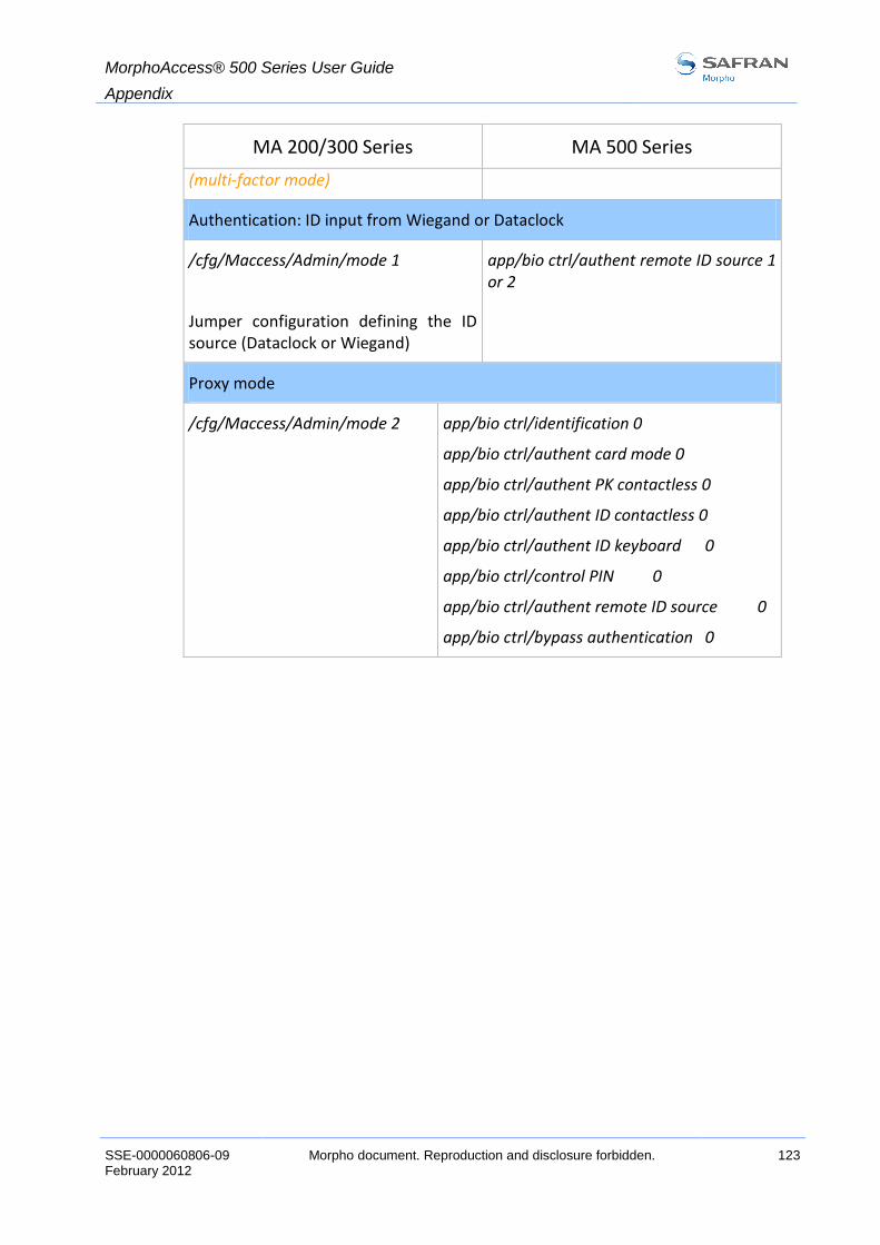
MorphoAccess® 500 Series User Guide
Appendix
SSE-0000060806-09 Morpho document. Reproduction and disclosure forbidden. 123 February 2012
MA 200/300 Series MA 500 Series
(multi-factor mode)
Authentication: ID input from Wiegand or Dataclock
/cfg/Maccess/Admin/mode 1
Jumper configuration defining the ID source (Dataclock or Wiegand)
app/bio ctrl/authent remote ID source 1 or 2
Proxy mode
/cfg/Maccess/Admin/mode 2 app/bio ctrl/identification 0
app/bio ctrl/authent card mode 0
app/bio ctrl/authent PK contactless 0
app/bio ctrl/authent ID contactless 0
app/bio ctrl/authent ID keyboard 0
app/bio ctrl/control PIN 0
app/bio ctrl/authent remote ID source 0
app/bio ctrl/bypass authentication 0

MorphoAccess® 500 Series User Guide
Appendix
124 Morpho document. Reproduction and disclosure forbidden SSE-0000060806-09 February 2012
CCoonnttaaccttlleessss mmooddeess ttaabbllee
Operation
Au
then
t ca
rd
mo
de
Au
then
t P
K
con
tact
less
Au
then
t ID
con
tact
less
Byp
ass
auth
enti
cati
on
Authentication with templates in database
Read ID on contactless card. Retrieve corresponding templates in database. Biometric authentication using these templates. Send ID if authentication is successful.
0 0 1 0
Authentication with templates on card
Read ID and templates on contactless card. Biometric authentication using these templates. Send ID if authentication is successful.
0 1 0 0
Card mode authentication
Read card mode, ID, templates (if required by card mode) on contactless card. If card mode is « ID only », send ID. If card mode is « Authentication with templates on card », biometric authentication using templates read on card, then send ID if authentication is successful.
1 0 0 0
Authentication with templates in database – biometric control disabled
Read ID on contactless card. Check corresponding templates presence in database. Send ID if templates are present.
0 0 1 1
Authentication with templates on card – biometric control disabled
Read ID on contactless card. Send ID.
0 1 0 1
Card mode authentication – biometric control disabled
Read card mode, ID, templates (if required by card mode) on contactless card. Whatever card mode, send ID.
1 0 0 1

MorphoAccess® 500 Series User Guide
Appendix
SSE-0000060806-09 Morpho document. Reproduction and disclosure forbidden. 125 February 2012
RReeqquuiirreedd ttaaggss oonn ccoonnttaaccttlleessss ccaarrdd
Operation ID CARD MODE
PK1 PK2 PIN BIOPIN
Authentication with templates in database
Yes No No No No No
Authentication with templates on card
Yes No Yes Yes No No
Card mode authentication (ID_ONLY)
Yes Yes No No No No
Card mode authentication (PKS) Yes Yes Yes Yes No No
Authentication with templates in database – biometric control disabled
Yes No No No No No
Authentication with templates on card – biometric control disabled
Yes No No No No No
Card mode authentication (ID_ONLY) – biometric control disabled
Yes Yes No No No No
Card mode authentication (PKS) – biometric control disabled
Yes Yes Yes Yes No No
BIOPIN check Yes No No No No Yes
PIN check Yes No No No Yes No

MorphoAccess® 500 Series User Guide
Support
126 Morpho document. Reproduction and disclosure forbidden SSE-0000060806-09 February 2012
SSuuppppoorrtt

MorphoAccess® 500 Series User Guide
Support
SSE-0000060806-09 Morpho document. Reproduction and disclosure forbidden. 127 February 2012
FFAAQQ
SSeennssoorr iiss ooffff
Check that the base contents at least one record.
Check that identification mode is enabled.
TTeerrmmiinnaall rreettuurrnnss eerrrraattiicc aannsswweerrss ttoo ppiinngg rreeqquueessttss
Check the subnet mask. Ask your administrator the right value.

MorphoAccess® 500 Series User Guide
Support
128 Morpho document. Reproduction and disclosure forbidden SSE-0000060806-09 February 2012
RReellaatteedd ddooccuummeennttss
AAddmmiinniissttrraattoorr IInnffoorrmmaattiioonn
MorphoAccess® 500 Series User Guide
This document describes operating mode and terminal settings
MorphoAccess® Parameters Guide
The complete description of terminal configuration files and registry keys
This document gives also parameters default values
MorphoAccess® 500 Series Configuration Application User Guide
This document describes the configuration application processing
MorphoAccess® 500 Series Enrolment application User Guide
This document describes the local enrolment process and features
MorphoAccess® 500 Series Log viewer User Guide
This document describes the log viewer process and features
IInnssttaallllaattiioonn IInnffoorrmmaattiioonn
MorphoAccess® 500 Series Installation Guide
This document describes installation operating and MorphoAccess® 500 Series interfaces features
DDeevveellooppeerr IInnffoorrmmaattiioonn
MorphoAccess® Host Interface Specification
A complete description of remote management commands
MorphoAccess® Remote Messages Specification
Details how the MorphoAccess® sends the access control result to a Central Security Controller
MorphoAccess® 500 Series User Guide
Support
SSE-0000060806-09 Morpho document. Reproduction and disclosure forbidden. 129 February 2012
MorphoAccess® Contactless Card Specification
This document describes the MorphoAccess® contactless card feature
SSuuppppoorrtt TToooollss
USB Network Tool User Guide
User guide about network configuration using USB flashdrive
MorphoAccess® Upgrade Tools User Guide
Upgrade Tool user guide about firmware upgrading procedures
Licence Manager User Guide
Download a licence in MorphoAccess® using “Licence Manager.exe” PC application

MorphoAccess® 500 Series User Guide
Support
130 Morpho document. Reproduction and disclosure forbidden SSE-0000060806-09 February 2012
CCoonnttaaccttss
CCuussttoommeerr sseerrvviiccee
Morpho
SAV Terminaux Biométriques
Boulevard Lénine - BP428
76805 Saint Etienne du Rouvray
FRANCE
Phone: +33 2 35 64 55 05
HHoottlliinnee
Morpho
Support Terminaux Biométriques
18, Chaussée Jules César
95520 Osny
FRANCE
Phone: + 33 1 58 11 39 19 19
(9H00am to 5H00pm French Time , Monday to Friday)
http://www.biometric-terminals.com/
To access this service, please contact us in order to get your login. Please send us an email rather than call by phone.
Copyright ©2012 Morpho
http://www.morpho.com/


Head office : Le Ponant de Paris 27, rue Leblanc - 75512 PARIS CEDEX 15 - FRANCE