Moroso Replacement Emission Control Parts Installation ... Insert Air Oil Separator into billet...
19
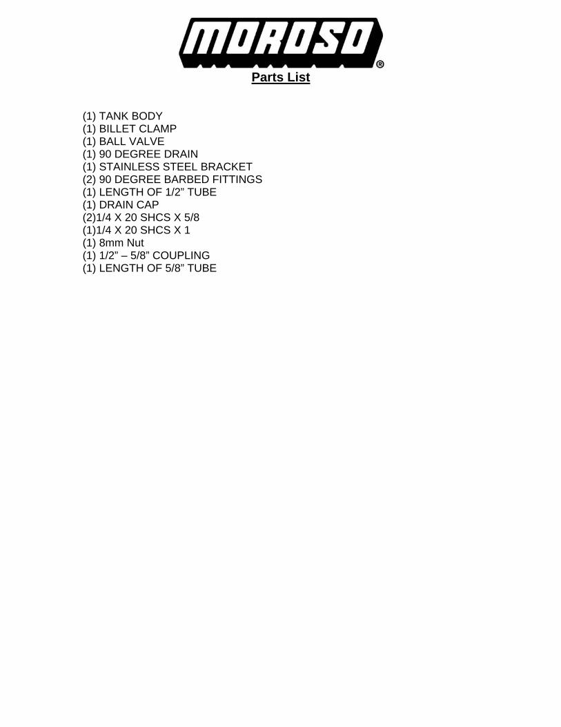
Parts List (1) TANK BODY (1) BILLET CLAMP (1) BALL VALVE (1) 90 DEGREE DRAIN (1) STAINLESS STEEL BRACKET (2) 90 DEGREE BARBED FITTINGS (1) LENGTH OF 1/2” TUBE (1) DRAIN CAP (2)1/4 X 20 SHCS X 5/8 (1)1/4 X 20 SHCS X 1 (1) 8mm Nut (1) 1/2” – 5/8” COUPLING (1) LENGTH OF 5/8” TUBE
Transcript of Moroso Replacement Emission Control Parts Installation ... Insert Air Oil Separator into billet...
Parts List
(1) TANK BODY (1) BILLET CLAMP (1) BALL VALVE (1) 90 DEGREE DRAIN (1) STAINLESS STEEL BRACKET (2) 90 DEGREE BARBED FITTINGS (1) LENGTH OF 1/2” TUBE (1) DRAIN CAP (2)1/4 X 20 SHCS X 5/8 (1)1/4 X 20 SHCS X 1 (1) 8mm Nut (1) 1/2” – 5/8” COUPLING (1) LENGTH OF 5/8” TUBE
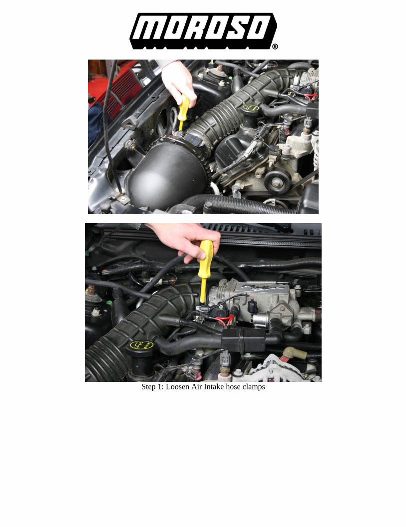
Step 1: Loosen Air Intake hose clamps

Step 2: Remove lines from Air Intake hose

Step 3: Remove Air Intake hose from throttle body
Step 4: Remove Air Intake hose from Air Cleaner Box, and remove from vehicle
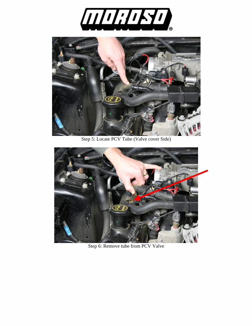
Step 5: Locate PCV Tube (Valve cover Side)
Step 6: Remove tube from PCV Valve
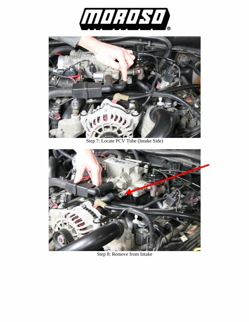
Step 7: Locate PCV Tube (Intake Side)
Step 8: Remove from Intake
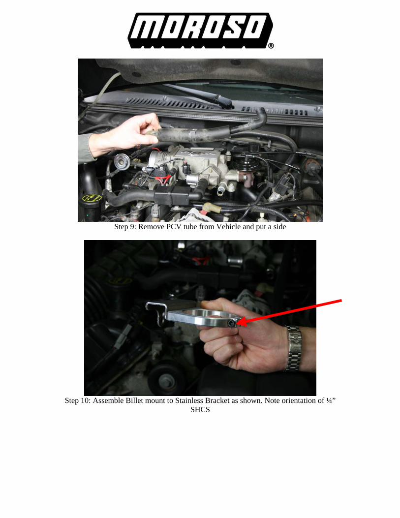
Step 9: Remove PCV tube from Vehicle and put a side
Step 10: Assemble Billet mount to Stainless Bracket as shown. Note orientation of ¼” SHCS

Step11: Locate 8mm stud as shown and install Billet Stainless Mount
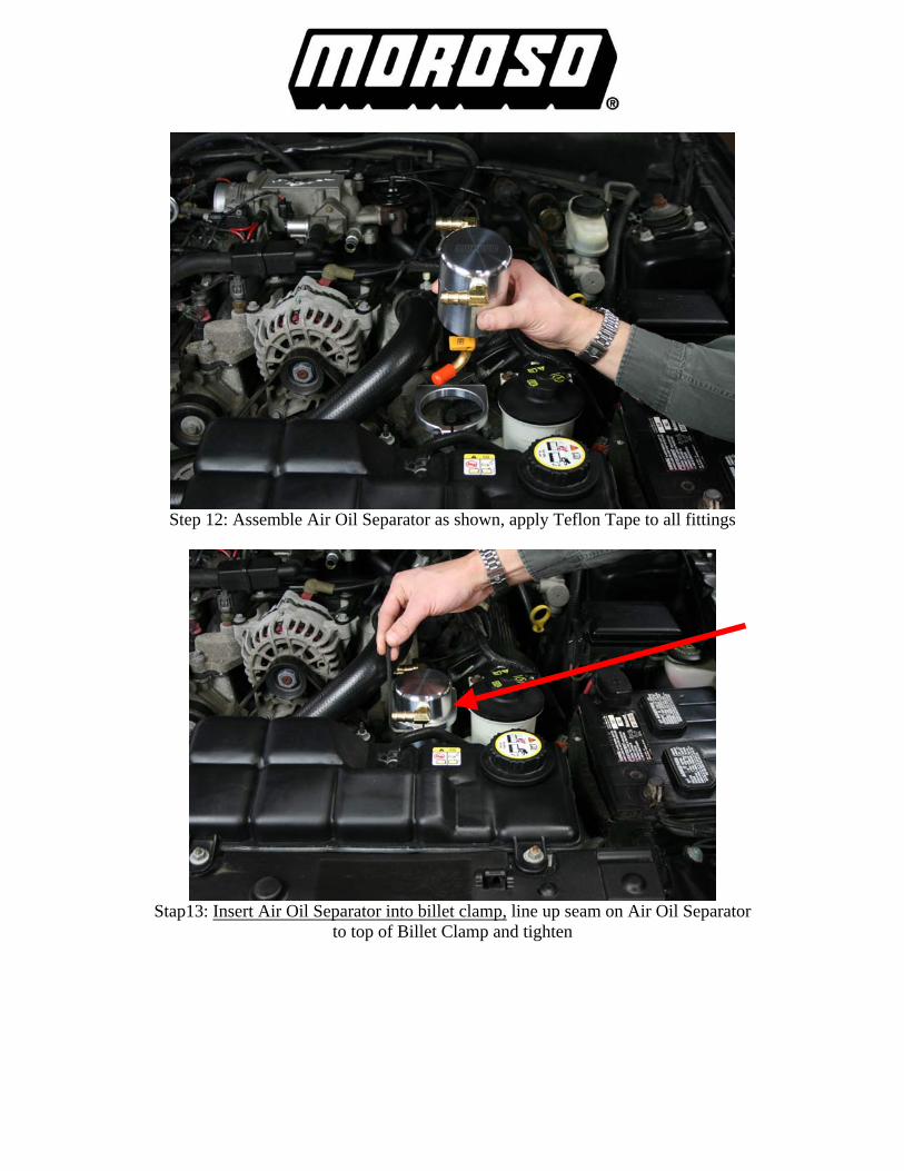
Step 12: Assemble Air Oil Separator as shown, apply Teflon Tape to all fittings
Stap13: Insert Air Oil Separator into billet clamp, line up seam on Air Oil Separator to top of Billet Clamp and tighten
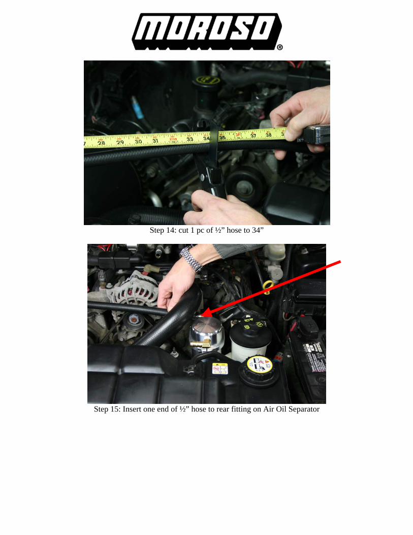
Step 14: cut 1 pc of ½” hose to 34”
Step 15: Insert one end of ½” hose to rear fitting on Air Oil Separator

Step 16: Route ½” hose from Air Oil Separator to Valve Cover as shown
Step 17: Remove 90 degree fitting from PCV tube previously removed

Step 18: Insert Nylon coupling into 90 degree fitting, install 90 degree fitting to PCV valve, trim ½” hose
Step 19: Insert ½” hose over coupling

Step 20: cut 1 pc of ½” hose to 20”
Step 21: Insert one end of ½” hose to front fitting on Air Oil Separator
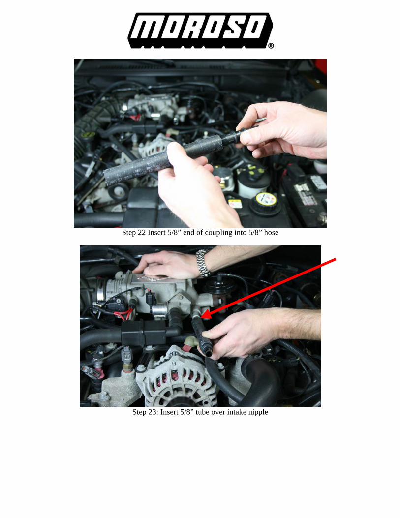
Step 22 Insert 5/8” end of coupling into 5/8” hose
Step 23: Insert 5/8” tube over intake nipple

Step 24: trim ½” hose previously installed from step 21
Step 25: Insert ½” hose over ½” coupling
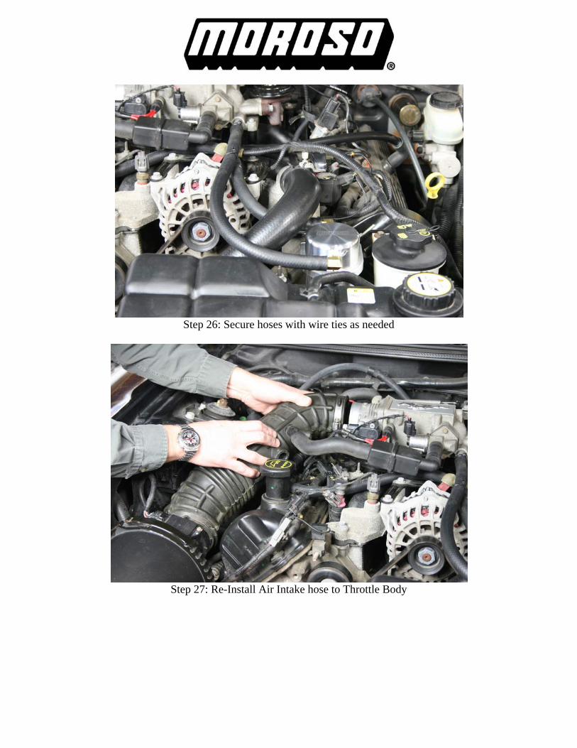
Step 26: Secure hoses with wire ties as needed
Step 27: Re-Install Air Intake hose to Throttle Body
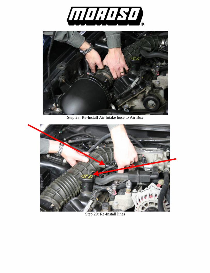
Step 28: Re-Install Air Intake hose to Air Box
Step 29: Re-Install lines
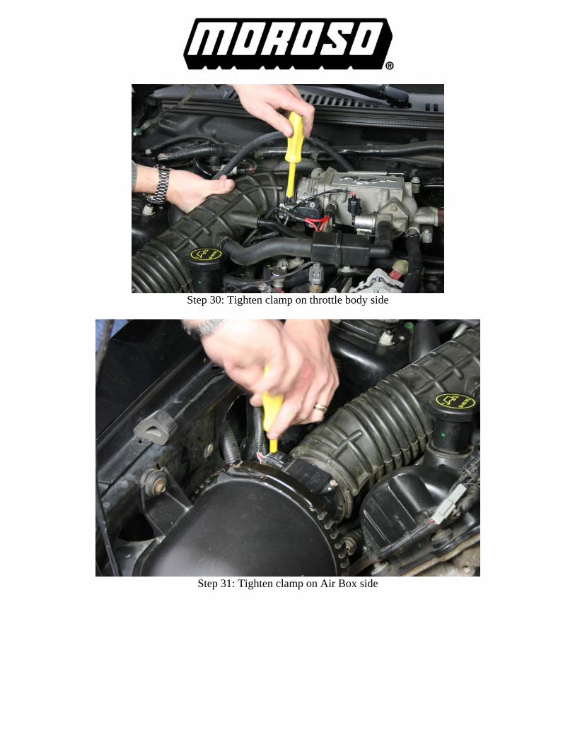
Step 30: Tighten clamp on throttle body side
Step 31: Tighten clamp on Air Box side

Installation Complete Draining of Air Oil Separator is needed; this will depend on driving conditions (i.e.) normal day to day driving check every 1,000 miles until a baseline is established. A good baseline is to drain the Air Oil Separator when it is about HALF full. This will
vary with temperatures (cold winters vs. hot summers). For track usage Air Oil Separator will need to be drained after every outing.
There are several different methods to draining Air Oil Separator. The first and simplest method is to place a cup or MOROSO part # 65805 under drain elbow and open ball valve, once draining is complete close ball valve. The second method is to run a length of ½” hose from elbow to under carriage of vehicle and place drain pan under vehicle at this time open ball valve, when draining is complete close ball valve. This hose may also be permanently installed for future draining.