Tender Invitation by Mormugao Port Trust for Solar EPC. To get BOM for this Tender, Visit
1
\\172.24.101.154\proj cell folder\Sagar Mala Project\Illumination of Rail Platform\NIBO for high mast
MORMUGAO PORT TRUST
ENGINEERING MECHANICAL DEPARTMENT
NOTICE INVITING BUDGETORY OFFERS
Name of Work
Supply, Installation ,Testing and Commissioning of 30 mtr High
Mast at Railway Platform / Yard at MPT
Date of submission of
offers
On or before 09.01.2017 at 1430 Hrs.
Address for
communication:
Superintending Engineer (E-P)
Engineering Mechanical Dept.,
Mormugao Port Trust,
Mormugao, Goa – 403802.
Contact Details
Phone :0832-2594269/ 2594229/2594260
Email : [email protected] , [email protected]
Website
www.mptgoa.com
CHIEF MECHANICAL ENGINEER
MORMUGAO PORT TRUST

2
\\172.24.101.154\proj cell folder\Sagar Mala Project\Illumination of Rail Platform\NIBO for high mast
TECHNICAL SPECIFICATION
1.0. GENERAL
Mormugao Port Trust is one of the ISO: 9001-2008 certified Major Port Trusts in India, under Ministry
of Shipping, Govt. of India. It is situated on the Western Coast of India, in the State of GOA at latitude
15o 25N and longitude 73o 47 E situated very close to the sea. The average atmosphere temperature
is 320 C.
2.0. SCOPE OF WORK
2.1. The scope work includes Design, Manufacturing, Supply, Installation, Testing and
Commissioning of 30 Mtr. High mast, Load Point, Feeder Pillar, Luminaries, Aviation Light, Lightning
Arrestor, LT XLPE cables, Earthing System and Protection Guard etc. Also it includes dismantling of
existing 30 Mtr. Highmast with complete accessories including light fixtures, etc. and re-erection of
the same at the new locations after refurbishment.
2.2. The work involves illumination of railway platform and lines for handling of loading and unloading
of cargo from the railway wagons.
2.3. The Contractor shall carry out High mast foundation based on the soil bearing capacity and
complete High mast load including light fixtures and accessories. The foundation shall be designed by
the OEM in such a way that the high mast shall withstand the wind speed of 200 Km/h and same
shall be submitted to MPT for approval by the Contractor.
2.4. The Luminaries shall be supplied 1 X 400W HPSV and 1 X 1000W HPSV Symmetrical flood
light with 400W Son-T lamp and 1 X 1000W Son-T lamp respectively with complete accessories.
Similarly, 2 X 400W HPSV Asymmetrical fixture with Son -T lamp (2 X 400W) with accessories. The
lumens output of each 400W Son-T lamp should be 55000 lm and 1000W Son-T lamp should be
130000 lm.
2.5. All the Electrical installation including Load Point, Feeder Pillar, High mast should be earthed
as per relevant IS Standard.
2.6. The subject work shall be carried out as per relevant IS standard and also execute the electrical
work as per Indian Electricity Rule (IER).
3
\\172.24.101.154\proj cell folder\Sagar Mala Project\Illumination of Rail Platform\NIBO for high mast
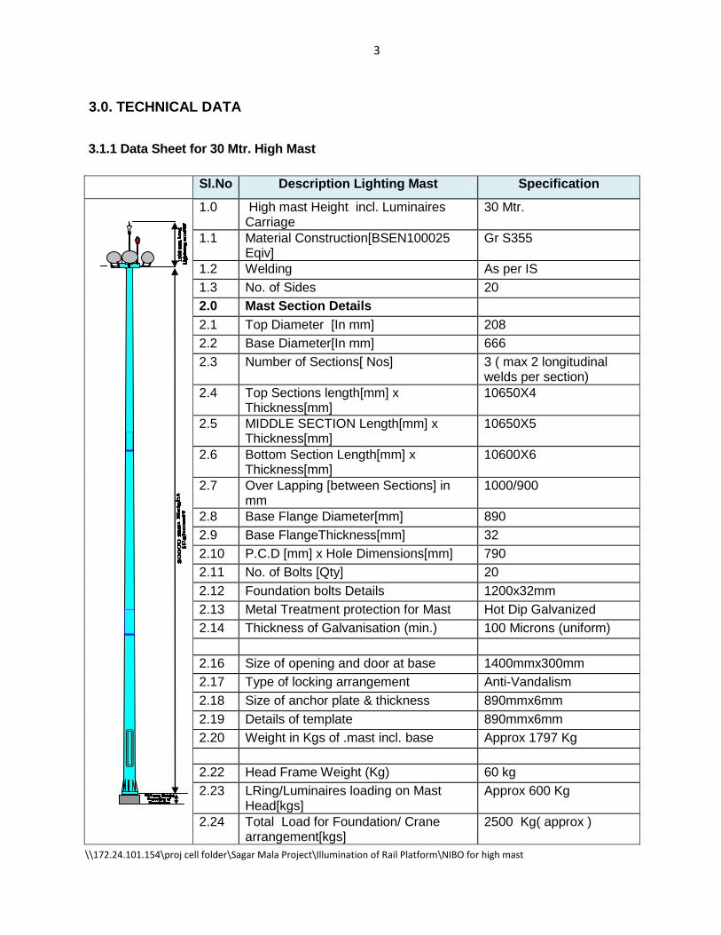
3.0. TECHNICAL DATA
3.1.1 Data Sheet for 30 Mtr. High Mast
Sl.No Description Lighting Mast Specification
1.0 High mast Height incl. Luminaires Carriage
30 Mtr.
1.1 Material Construction[BSEN100025 Eqiv]
Gr S355
1.2 Welding As per IS
1.3 No. of Sides 20
2.0 Mast Section Details
2.1 Top Diameter [In mm] 208
2.2 Base Diameter[In mm] 666
2.3 Number of Sections[ Nos] 3 ( max 2 longitudinal welds per section)
2.4 Top Sections length[mm] x Thickness[mm]
10650X4
2.5 MIDDLE SECTION Length[mm] x Thickness[mm]
10650X5
2.6 Bottom Section Length[mm] x Thickness[mm]
10600X6
2.7 Over Lapping [between Sections] in mm
1000/900
2.8 Base Flange Diameter[mm] 890
2.9 Base FlangeThickness[mm] 32
2.10 P.C.D [mm] x Hole Dimensions[mm] 790
2.11 No. of Bolts [Qty] 20
2.12 Foundation bolts Details 1200x32mm
2.13 Metal Treatment protection for Mast Hot Dip Galvanized
2.14 Thickness of Galvanisation (min.) 100 Microns (uniform)
2.16 Size of opening and door at base 1400mmx300mm
2.17 Type of locking arrangement Anti-Vandalism
2.18 Size of anchor plate & thickness 890mmx6mm
2.19 Details of template 890mmx6mm
2.20 Weight in Kgs of .mast incl. base Approx 1797 Kg
2.22 Head Frame Weight (Kg) 60 kg
2.23 LRing/Luminaires loading on Mast Head[kgs]
Approx 600 Kg
2.24 Total Load for Foundation/ Crane arrangement[kgs]
2500 Kg( approx )

4
\\172.24.101.154\proj cell folder\Sagar Mala Project\Illumination of Rail Platform\NIBO for high mast
Sl.No Description Lighting Mast Specification
3.0 Foundation Details
3.1 Type of Foundation Open Raft Type
3.2 Foundation design As per soil bearing capacity and Highmast Load.
3.3 Designed load bearing capacity To be given by contractor
3.4 Design safety factor >2
4.0 HEAD FRAME 3-POINT
4.1 Construction MS. Fabricated
4.2 Metal Treatment protection for HEAD
FRAME Hot Dip Galvanised
4.3 PULLEY ARRANGEMENTS[ FOR
STEEL WIRES] 3SETS OF PULLEYS
4.4 PULLEY ARRANGEMENTS[ FOR
ELECTRICAL CABLES] 1 set OF PULLEY
5.0 LANTERN CARRIAGE
5.1 Material of Construction IS2062
5.2 Diameter of Carriage Ring(mm)-1NO 1200/1600
5.3 Construction M.S fabricated
5.4 Number of joints 3
5.5 Buffer arrangements between
Carriage& MAST To be provided
6.0 COMPENSATING DISC BETWEEN
L/RING & D/D WINCH PROVIDED
7.0 SAFETY LOCKING ON BOTH SIDES
OF BASE OF MAST PROVIDED
8.0 Winch D/Drum, 750 Kg cap
9.0 Stainless Steel wires diameter 8 mm (thickness)
9.1 Number of Ropes 3
9.2 C/disc to D/d. Winch two[8mm size]
9.3 C/disc to Lantern Ring Three[8mm size]
9.4 Thimbles & Terminals Provided.
9.5 Factor Of Safety >5
10.0 POWER TOOL Integral
10.1 Model Crompton greaves/Bajaj
10.2 Input Supply 415v,50c/s;3-ph
10.3 WATTAGE 1.5KW

5
\\172.24.101.154\proj cell folder\Sagar Mala Project\Illumination of Rail Platform\NIBO for high mast
Sl.No Description Lighting Mast Specification
10.4 Num. Of Speeds Single
10.5 Reversible/Non-reversible Reversible
10.6 Operating Speed 1400 Rpm
10.7 Wind Speed 200 Km/h wind speed
withstand by Mast
11.0 Lightning Arrestor [1.2m Length] To be provided
12.0 Aviation Obstruction light – LED type To be provided
13.0 Earthing with two earth pits To be provided
3.1.2 Mast Design Criteria
The mast shall be designed in such a manner that it is capable of withstanding external forces
exerted by wind speed as per relevant standards and should have a minimum wind load factor of
1.25.
3.1.3 Applicable Standards
The following shall be the reference standards for manufacture and design compliance of High
Mast:
3.1.4. Structure
The high mast structure shall be of continuously tapered polygonal cross section [at least 20 sided
for16M and above]. The Mast structure should be pleasant in appearance & designed for suitable
wind loads minimum 200Km / hr.
Sl. No.
Code No. Title
a) I.S.875 (PART III) -1987 Code and Practice for wind loads.
b) BS code of practice CP-3 chapter V part -II Gradient of wind speed related to height above ground
c) I.L.E.TR-7, Latest Edition Specification For Mast /Foundation
d) BS5649, PART-7 Structural Design
e) BSEN 100025/100027, BS 4360 /DIN 17100 Mast Sections
f) IS 2062. Base plate, Top plate and Accessories
g) BS 5135 or IS 9595 Welding
h) BS 729 / IS 2629/ BS ISO 1461 Galvanizing
i) BIS 10947-1984 Lighting for ports and Harbours
j) BIS 3043-1987 Earthing
6
\\172.24.101.154\proj cell folder\Sagar Mala Project\Illumination of Rail Platform\NIBO for high mast
3.1.5. Construction
The mast sections shall be manufactured from special steel sheets conforming to BSEN
100025/100027/ DIN 17100/ BS 4360 or equivalent cut and folded to form a continuously tapered
polygonal section having a single longitudinal weld by MIG welding process. The welding shall
comply BS 5135 or IS 9595. Masts shall be delivered in multiple sections which shall be
assembled at site by slip-stress-fit method. The minimum overlap distance shall be 1.5 times the
diameter at penetration. There shall be no circumferential welding in any section. No site welding
or bolted joints in the mast sections shall be allowed. The dimensions of the mast sections shall be
decided based on sound and established design norms as per BS 5649 & ILE TR7.
The Base and Top plates without any laminations shall be welded to the bottom and top sections
respectively. The welded joints shall be fully penetrated and developed to the strengths of the
respective sections. The Base and Top plates shall be provided with supplementary gussets
between the bolt holes to ensure elimination of helical stress development.
Mast base section will have a lockable door of size 1400mm X 300mm for easy access to winch
and power tool operations. Bottom of door shall be 600mm above the top of the base plate. The
door design shall be done in accordance with relevant standard and practices and adequately
reinforced for prevention against buckling.
Provisions for fixing safety wires shall be made in the bottom section.
All sections shall be hot dip galvanized as per BS 729/IS 2629. The galvanization shall be done by
single dip method for uniform thickness of minimum 100 micron and better aesthetic appearance.
3.1.6. Dynamic Loading
The Mast sections should be designed based on basic wind speed data as mentioned at 10m level
as per IS:875, Part-III, 1987. The structural design of the mast shall comply with BS 5649 part VII
and ILE TR 7 guidelines.
The foundation design shall be made by taking into considerations the following:
1. Dynamic loading on the mast as per ILE TR 7 and IS 875 and
2. Static load of the total mast structure
3. RCC Foundations and Soil conditions.

7
\\172.24.101.154\proj cell folder\Sagar Mala Project\Illumination of Rail Platform\NIBO for high mast
The High Mast Towers along with base plate shall be erected on the concrete foundation as per
firms design approved by Mormugao Port Trust. The firms shall furnish necessary RCC foundation
drawing for approval based on the soil bearing capacity Test results. The foundation shall be
designed to meet the soil conditions. The foundation provided shall have adequate bolts of
adequate diameter and height for anchoring the base plate of the mast. The contractor shall
ensure correct vertical and horizontal alignment of the foundation bolts while carryout the
foundation works by using suitable steel template. The height of the foundation shall be 500
mm above the nearby plinth level of building.
3.1.7 Raising and Lowering Mechanism
The high-mast shall have an optimally balanced system for raising and lowering of the Luminaries
and control gear boxes for regular maintenance work. The same shall be provided by means of a
double drum winch with double gear fixed at the base, 3 wire suspension wire ropes along with
compensating disc and safety wires, a specially designed 6 pulley head frame assembly. The
winch mechanism shall be suitably connected to “fixed 3 phase, 415 V Electric Motor” and is
operated through forward and Reverse Contactor with push button control to raise/lower the
lantern carriage.
3.1.8 Accessories
3.1.8.1. Head Frame
M.S. fabricated hot dip galvanized housing using IS2062 grade steel accommodating 6 CA pulleys
with stainless steel pins for the suspension wire ropes and upto 3 such smaller pulleys for the
electrical cables. Pulleys are grooved suitably to ensure that the wire ropes/cables do not get
dislodged from their positions while raising / lowering. Self-lubricating bearings and stainless steel
shaft shall be provided for smooth and maintenance free operation throughout the mast life.
The head-frame shall be made in three compartments placed 120 degree apart for most optimum
balancing of lantern carriage. Head frame shall have top canopy in tripod shape to protect the mast
from entry of water / solid particles etc from the top. Also, top canopy shall have provision for fixing
lightning arrestor of suitable design.
3.1.8.2 Lantern Carriage
A fabricated MS hot dip galvanized lantern carriage shall be provided for mounting of luminaire arm
assemblies. The lantern carriage shall be made of specially designed square steel tube having a
three-piece construction. The flanges shall be jointed at site by stainless steel bolts and nuts. Inner
side of the lantern carriage shall be provided with a separate guide ring with rubber padding to

8
\\172.24.101.154\proj cell folder\Sagar Mala Project\Illumination of Rail Platform\NIBO for high mast
protect the mast surface while raising and lowering of the lantern carriage. The diameter of the
lantern carriage shall not be less than 1200mm. However, it should be designed to provide 12KW
luminaries ( 6 Nos. 1 X 400W, 8 Nos. 2 X 400W, 2 Nos. 1 X 1000W)
3.1.8.3 Luminaire Arm Assembly & Flood Light Fixtures
Luminaire arm assembly shall be fabricated MS hot dip galvanized to be fixed on the lantern
carriage for mounting of luminaries and CG Boxes. Each arm shall be suitable for accommodating
flood lighting luminaries and their CG boxes.
3.1.8.4 Flood Light Fixtures:
a) The specially designed Non-Integral flood light fixtures on the lantern carrier of high mast with
corrosion resistant housing, Copper wound ballast, capacitor, igniter, lamp holder, earthing
terminal, lamp, wiring, etc. complete as required as per specifications mentioned in the BOQ and
approved drawings. The luminaries shall be tested as per Indian Standards and test reports shall
be submitted along with the materials.
b) The luminaries mounting bracket shall be epoxy grey powder coated MS hot dip galvanised with
graduated aiming disc and locking facility at any angle in the vertical plane. The luminaries shall of
Class – I Electrical safety and should be easy to install and maintenance.
c) The control gear box shall be cast aluminium, weatherproof, heavy duty, loop-in loop-out facility
and epoxy grey powder coated & hinged cover with rubber gasket. The control gear box shall be
housed with copper ballast, capacitor, electronic igniter, porcelain re-wireable fuse cutout and
earthing terminal suitable for flood light fixtures as mentioned in the BOQ. It should be pre-wired
with PVC insulated copper wires upto the terminal block. The control gear box shall be Class – I
Electrical Safety with Degree of Protection IP-65.
3.1.8.5 Suspension Wires
Three-wire suspension assembly from compensating disc to the lantern carriage shall be made of
8 mm dia stainless steel wire rope as per AISI 316 or better Grade. No joints shall be allowed in
any length of the wires. The ends of the wire rope shall be suitably secured in the winch block with
thimbles.
The wires from compensating disc to the double drum winch shall be made of 8 mm dia stainless
steel wire rope of the same grade as above.

9
\\172.24.101.154\proj cell folder\Sagar Mala Project\Illumination of Rail Platform\NIBO for high mast
Breaking load capacity of each wire rope shall not be less than 2100kg with a factor of safety not
less than 5.0. The Manufacturer Test certificate for the rope shall be produced.
3.1.8.6 Compensating Disc
A separator of MS Construction hot dip galvanized having provision for fixing 3 nos suspension
wires on upper deck at 120 degree apart and provision of fixing two nos. wires from double drum
winch. It will also have the provision to connect two nos. safety wires from both side of the base of
the mast.
Shape/size of the compensating disc shall be designed for its free movement up to top of the mast.
When the lantern carriage is at mast top, the compensating disc position shall be at door level.
Compensating Disc is mandatory as per I.L.E., TR-7. Compensating disc enables dismantling of
D/D (Double Drum) winch which is essential during the design life of the mast, by way of the safety
wires.
3.1.8.7 Double Drum Winch
The double drum winch with double gear shall be completely self sustaining type without the need
for brake shoe, springs and clutches. The winch shall have self lubrication mechanism by means of
an oil bath. The winch assembly shall have simultaneous and reversible operation of double
drum winch with double gear. The gear assembly shall be essentially made of phosphor bronze
for optimum design life.
The gear ratio shall be 53:1 and safe working load capacity shall not be less than 750 kg. for masts
of height 16m and above.
The winch drums shall be grooved to ensure perfect seat for stable and tidy rope lay with no
chances of slipping of ropes. The rope termination in the winch shall be such that distortion or
twisting is eliminated and at least 5 to 6 turns of rope remain on the drum even when the lantern
carriage is at fully lowered position. It should be possible to operate the winch manually by a
suitable handle or by an integral power tool. It shall be possible to remove the winch after
dismantling it from its mounted position and re-fix it through the door opening.
Type test certificate for similar type of Winch manufactured be submitted by the successful bidder.
3.1.8.8 Electrical Hoist Cables
The electric cable shall be 2 x 5 core X 4.0 sq.mm. round type made of strands of plain copper
wires ATC conductor, EPR insulated, Cotton braided and PCP outer sheathed black cable and

10
\\172.24.101.154\proj cell folder\Sagar Mala Project\Illumination of Rail Platform\NIBO for high mast
flame retardant to get flexibility and endurance with Rodent proof coating, core identification in
accordance with relevant IS standard.
The cable shall be highly flexible for optimum design life and the bending radius shall be not more
than 60mm and VDE (or equivalent) approved for hoist applications.
Base end of the cable shall be connected with a 5 pin male metal clad plug which can move
easily with the cables during raising/lowering. A 5 pin metal clad socket shall be provided at the
bottom of the mast for cable termination.
The trailing cable to the high mast shall be rodent proof.
3.1.9 Junction Box
One or more Weather proof junction box IP 65 made of Cast Aluminium shall be provided on the
lantern carriage for connecting the luminaries, control gears and the cable. The number of ways is
decided by the no. of luminaries to be connected. The connectors shall be CBT type Terminals.
3.1.10 Power Tool and Control Panel
A suitable high powered, electrically driven and electrically controlled, portable, internally mounted
power tool with manual over ride shall be provided for the raising and lowering of the lantern
carriage.
The power tool mounting shall be so designed that it will not only be self supporting type but also it
shall align itself perfectly with respect to the winch spindle during the operations. A handle for
manual operations shall be provided as per standard practices.
Power tool shall consist of 3-phase 415volts, 50c/s motor and a gear box to match winch gear ratio
duly coupled with each other. It shall be of reversible speed type.
A controlling unit for rotation changes of motor with provision of torque limiter by way of using
electric circuits for electrical protection shall be provided.
3.1.11 Electrical Distribution Board at the Base of Mast
A suitable board of non-hygroscopic material shall be provided at the base of the mast at door
level. This will have four pole MCB of suitable rating for the lighting load of the mast for each circuit
and CBT Connectors for cable Termination. The MCBs will terminate the in-coming supply and can
be used as a local isolator during maintenance work. The system shall have in-built facilities for
testing the luminaries while in lowered position.

11
\\172.24.101.154\proj cell folder\Sagar Mala Project\Illumination of Rail Platform\NIBO for high mast
One or more 5 pin socket(s) shall be mounted for the electric cable(s). A 5-pin power socket shall
be provided for 3-phase power tool operation.
3.1.12. Erection of Highmast:
The Contractor shall carry out High mast foundation based on the soil bearing capacity and
complete High mast load including light fixtures and accessories. The foundation shall be
designed by the OEM in such a way that the high mast shall withstand the wind speed of 200
Km/h and same shall be submitted to MPT for approval by the Contractor.
The erection, testing and commissioning of 30 Mts. High mast system on civil foundation
complete with all accessories i.e. Flood Light Tower including High Mast, Lantern Carriage
Assembly, Headframe , Winch Assembly, Power Tool for Winch Drive, Junction Box/Switches,
necessary cabling from Feeder Pillar to individual Lighting Fixtures, Termination of Aviation Light,
steel wire rope (S.S 316), foundation bolts, lantern carriage, lighting finial and earth strip etc.,
The Contractor shall provide all tools and tackles including Crane for erection of high mast.
Cable shall be taken to the base compartment of the high mast through the provision made in the
foundation. The Incoming Power cable for lighting and motor from control panel to the base
compartment of the high mast shall be included in the High mast price and no separate item / qty.
is considered. Quoted rate must be covered the above work having explicitly stated in the
following paragraphs or if not shall be included by the Tenderer for smooth safe and efficient
operation and maintenance of the High Mast System. The work shall be carried out with all
materials & labours as directed by Engineer–in-charge.
3.1.13 Back to Back Support of Manufacturer:
The Contractor shall have back to back Support from OEM for installation, testing, Commissioning
of High Mast including Civil Foundation.
3.2. LOAD POINT PANEL
Design, Manufacture, Supply, Installation, testing and commissioning of Load Point Panel
Outdoor Pedestal type with top Canopy. It shall be IP 65 compliant, dust, damp, vermin and
weather proof fabricated from SS-316 grade Sheet of 2 mm. thick and shall be fabricated with
the SS-316 angle & flat of suitable size as directed. It shall be provided with double shutter,
handle with lock & key system (pad lock – 5 levers with keys). The drawing of the Panels shall be

12
\\172.24.101.154\proj cell folder\Sagar Mala Project\Illumination of Rail Platform\NIBO for high mast
got approved from Engineer-in-Charge prior to manufacture. The Load Point Panel shall be
spacious for easy maintenance and shall be provided with following Items.
i) 200 Amps, 35 KA, TPN MCCB – 1 No. For Incoming
ii) 63 Amps, 25 KA, TP MCB – 04 Nos. For Outgoing to Highmast
iii) 100 Amps, 25 KA, TP MCCB – 01 Nos. For Incoming /Outgoing to Load point Panel
iv) Neutral Link – 01 Nos
v) LED type indication Lamp 22.5 mm in Size, 220 V AC (Phase R, Y & B) – 03 Nos.
The components are to be interconnected for 3 phase and Neutral by suitably sized copper
busbars and PVC sleeved with colour code. Outgoing connectors for four outgoing cables and
spares are to be provided on a strip.
All these components shall be mounted in the Load Point Panel by means of suitable cadmium
passivated hardware. The Panel shall be complete in all respects with cable glands, lugs for
incoming and outgoing cables including interconnection with PVC insulated cable single core,
standard copper conductor of 700/1100V grade.
Load Point Legs shall be stainless steel legs of 316-grade in reinforced foundation of suitable
design.
The Load Point Panel shall be tested as per IS: 4237. All the components shall be panel
mounting type and hardware cadmium passivated and shall be provided with 2 Nos. SS
terminals for earthing.
Erection of Load Point Panel
Erection, testing and commissioning of supplied load point panel on cement concrete platform
duly plastered with tapped collar of suitable size having height of 750 mm. above ground and
shall be grouted below ground level by providing reinforced foundation of suitable design. The
work includes all materials & labour as directed by Engineer-in-Charge.
3.3. FEEDER PILLAR
Design, Manufacture, Supply, Installation, testing and commissioning of Feeder pillar Outdoor
Pedestal type with top Canopy. It shall be IP 65 compliant, dust, damp, vermin and weather proof
fabricated from SS-316 grade Sheet of 2 mm. thick and shall be fabricated with the SS-316 angle
& flat of suitable size as directed. It shall be provided with double shutter, handle with lock & key
system (pad lock – 5 levers with keys). The drawing of the Panels shall be got approved from

13
\\172.24.101.154\proj cell folder\Sagar Mala Project\Illumination of Rail Platform\NIBO for high mast
Engineer-in-Charge prior to manufacture. The Feeder Pillar shall be spacious for easy
maintenance and shall be provided with following Items.
i) MCB, TPN, 63 A x 415 Volt, 25 KA, 50 Hz. - 1Nos.(As Incomer)
ii) Time Clock switch, 16 A - 1 No.
iii) 3 phase Air Break Contactor of 40 A capacity - 1 No.
iv) 32 Amp MCB, TP, Volt, 25 KA, 50 Hz. - 2 Nos.
v) Indicating Lamp - 1 Set (R, Y, B)
The suitable size and rating of electrolytic grade copper conductor/bus, phase to phase and
Neutral with PVC sleeved colour code shall be provided.
All these components shall be mounted in the feeder pillar by means of suitable cadmium
passivated hardware. The Feeder pillar shall be complete in all respects with cable glands, lugs
for incoming and outgoing cables including interconnection with PVC insulated cable single core,
standard copper conductor of 650/1100V grade.
The incoming cables shall be terminated on each MCB and the outgoing supply from the each
MCB shall be connected to busbar through Time Clock Switch and the contactor. From busbar
the outgoing shall be connected to the cable for high mast through 32 Amp TPN, MCBs.
The Feeder Pillar shall be provided with 2 Nos. SS terminals for earthing.
The relevant test certificate in support of SS Grade 316 shall be supplied along with drawing for
approval of MPT.
Erection of Feeder Pillar
Erection, testing and commissioning of supplied Feeder Pillar panel on cement concrete platform
duly plastered with tapped collar of suitable size having height of 750 mm. above ground and
shall be grouted below ground level by providing reinforced foundation of suitable design. The
work includes all materials & labour as directed by Engineer-in-Charge
3.4 LUMINAIRES & LAMPS
(i) 2 X 400 Watt Fixture For Asymmetrical arrangement
This includes supply of flood light luminaries suitable for twin 400W HPSV lamp including control
gear and 2 Nos. 400W HPSV SON-T lamp. The floodlight shall give asymmetrical distribution.
(ii) 1 X 400 Watt Fixture For Symmetrical arrangement
This includes supply of flood light luminaries suitable for single 400W HPSV lamp including
control gear and 400W HPSV SON-T lamp. The floodlight shall give symmetrical distribution.

14
\\172.24.101.154\proj cell folder\Sagar Mala Project\Illumination of Rail Platform\NIBO for high mast
(iii) 1 X 1000 Watt Fixture symmetrical Type
This includes supply of flood light fixtures suitable for Single 1000W HPSV lamp including control
gear and 1 Nos.1000 W HPSV SON-T lamps. The floodlight shall give symmetrical distribution
(a) Details: Heavy duty flood light luminaries suitable for above fittings should give symmetrical /
asymmetrical distribution and should have following components.
Reflector: The reflector frame assembly should be made of high purity aluminum
electrochemically brightened anodized for maximum utilization of lamp lumens and effective
beam control.
Rear Housing and Cover: This should be made of die cast LM-6 grade aluminum housing with
fins for effective cooling with lamp holder mounted in main luminaries housing with centering
and focusing device for good beam control. The lamp replacement should be easy from the rear
without disturbing previously set focusing.
Glass Cover Assembly: The reflector should be closed from front by resistant toughened glass
and synthetic weather proof gasket.
Mounting Bracket: The M.S. mounting bracket should allow fixation of flood light in horizontal
plane in any position with locking arrangement at any set angle in vertical chain to hold the
cover when reclamping.
Control Gear Box: The control gear box shall be fabricated from LM-6die cast aluminum and
shall also have weather proof construction using neoprene gasket and suitable for outdoor
installation. The control gearbox shall be provided with copper wound Epoxy filled ballast(s),
ignitor (s), P.F. correction capacitor(s), fuse(s) of appropriate rating and shall be mounted on a
removable gear tray duly pre wired up to the terminal block(s).
Cable Entry: A threaded inlet suitable for cable gland shall be provided for incoming cable
which terminates at a connector at the rear portion of casing. This also includes supply of
connecting of 4C X 2.5 Sq. mm. copper conductor PVC insulated PVC sheathed armoured
cable to connect control gear box with luminaries.
(b) Installation and Commissioning
Fixing, testing, termination and commissioning of supplied Flood Light Luminaries along with
their ballasts & other accessories on the carriage of the High Mast. The Mounting Angle shall be
such that the light on the desired area shall be optimum to meet the requirement of minimum 25
lux as per prevailing rules. The work includes all materials & labour as directed by Engineer-in-
Charge.
15
\\172.24.101.154\proj cell folder\Sagar Mala Project\Illumination of Rail Platform\NIBO for high mast
3.5. SUPPLY OF LT CABLE
The supply of LT XLPE Aluminium armoured conductor at site, 1.1 KV grade of size 3.5 core X
25 sq.mm. and 3.5 core X 120 sq. mm., as per relevant IS with up to date amendments and of
approved make with ISI mark. The cable shall supply in a single length and have
marking/embossing at the interval of every meter showing its progressive length.
The manufacturer shall produce TYPE TEST certificate with similar size and rating of cable,
which shall not be more than 3 years old. During the cable inspection, the manufacturer shall
show the relevant ROUTINE TESTS to inspecting authority or otherwise the manufacturer shall
produce the routine test certificate during supply of cable at site.
Laying of cable in Hard/soft soil
This includes laying of LT XLPE armoured cable of 1.1KV Grade through excavation in soft/hard
soil. The trench to be excavated 0.3 mtr. wide 1 mtr. deep. The bed of 50mm of sand shall be
provided in the bottom of the excavated trench. The cable shall be laid parallel to each other over
the bed of sand. The cable shall be covered by keeping two bricks over the side bricks shown in
the sketch. The filling of the trench shall be done with the excavated stuff & should be watered
and rammed properly to its original position. The excess excavated stuff shall be disposed off
from the Site of work and spreaded in low laying area as directed. This includes all labour and
material as directed by Engineer-in-Charge.
Laying of cable in RCC Trench
This includes laying of LT XLPE armoured cable of 1.1KV Grade through existing RCC trench.
The cable shall be laid after opening of RCC trench by removing the RCC/MS Cover plates &
cable trench shall be cleaned properly including removal of garbage, dust, etc from the trench
line without damaging the other cables laying in the trench. After laying of the cable, cable trench
shall be properly covered with existing cover plates as per original. This work includes all labour,
tools tackles, as directed by Engineer-in-Charge.
The contractor shall avoid the cable joint if required as per the site condition they provide heat
shrinkable straight through joint of relevant size of approved make on free of cost.

16
\\172.24.101.154\proj cell folder\Sagar Mala Project\Illumination of Rail Platform\NIBO for high mast
3.6. Aviation Light Fixtures
Supply of twin omni directional Aviation Obstruction Light Fixtures of LED type lamp complete
unit in all respect. The body material of the fixture shall be made of die casted aluminum with
yellow painting and shall have polished acrylic / glass holder. The unit shall be weather proof and
shall be outdoor mounting type and shall be suitable to operate on 230 V, 50 Hz. AC Supply.
Installation and Commissioning of Aviation Light Fixtures
Fixing, testing, termination and commissioning of supplied Twin Aviation Obstruction Light
Fixture at a suitable location in the carriage of High Mast. The work includes all materials &
labour as directed by Engineer-in-Charge.
3.7. Lightning Finial
The lightning protective system shall comply with all currently applicable standards, regulations and
safety codes of the locality where the installation shall be carried out. The installation work shall
confirm to the latest IE rules, standards (IS:2309 for lightning protection) and other relevant code of
practices.
One number heavy duty hot dip galvanized lightning finial shall be provided for each mast. The
lightning finial shall be minimum 1.2 M in length and shall be provided at the center of the head
frame. It shall be bolted solidly to the head frame to get a direct conducting path to the earth
through the mast. The lightning finial shall not be provided on the lantern carriage under any
circumstances in view of safety of the system. Lightning protection system down conductor shall
not be connected to other earthing conductors above ground level. Also no intermediate earthing
connection shall be made to the lightning arrestor which shall be directly connected to the
electrode. GI strip of size 50x6 mm shall be used for lightning.
3.8. EARTH PITS AND EARTHING:
The earthing system shall be designed and installed so as to meet the requirement of CEA for
the entire High mast installation, which include LT installations.
The value of resistance of earth system should not exceed value acceptable to the Central
Electricity Authority. The earth value shall be obtained in accordance with relevant standards and
the earth values shall be measured after installation, in the presence of Engineer-in-charge.
The earth connection shall be made of GI strip of 50 X 6 size conforming to IS 3043 to safely
carry the maximum fault current for a short period without burning the conductor. At no time the
potential shall exceed 10 volts between the equipment and earth. The earth system shall be
17
\\172.24.101.154\proj cell folder\Sagar Mala Project\Illumination of Rail Platform\NIBO for high mast
mechanically robust and joints shall be capable of retaining low resistance even after many
passages of fault current.
Interconnections and joints for earth conductors shall be riveted and soldered for maintaining low
resistance. Each earth bar should be connected to the main earth through a bolted removable
link. All ground connections shall be compounded and braided.
The earthing with copper plate shall be carried out in accordance with IS 3043 and IER amended
upto date. The earth electrodes shall be driven to a depth of not less than 2.7 meters below the
ground level and at least 3 meters away from the building and any other earth electrodes treating
the soil surrounding the electrodes with the salt, coke and charcoal (drawing enclosed)
The internal diameter of the cast iron earth electrode shall not be less than 100mm. The
thickness of the cast iron pipe shall not be less than 13mm.The electrode shall as far as
practicable be embedded below permanent moisture level and placed without over lapping the
resistance area of earth electrodes. Suitable size flange shall be provided to the cast iron pipe for
connecting the earth leads.
A suitable brick cemented enclosure for neutral and body earth will be as per IE Rule (i.e)
450mm x 450mm with 125mm wall thickness. The depth of the masonry work will be not less
than 600mm below the ground level and with suitable cover provided by the contractor enclosing
the earth electrodes and shall be able to take up the load of lorries, etc., operating in that area.
The top surface of the earth pit shall be in level with the finished surface level of the surrounding
area.
G.I. STRIP
The G.I. strip also shall be connected from earth station to individual H.M. Towers , Load Point
Panel , Feeder Pillar Panel, LT switch gears (Inside the Substation) etc. directly connected to two
separate and distinct main earth and shall be clamped suitably on wall /floor or buried in the
ground/pucca trench as directed. The work includes all material & labour required shall be done
as directed by Engineer-in-Charge. The pieces of GI strips shall be connected using GI nut bolts
rigidly and the GI strip shall be laid either on RCC with proper clamping or in the ground
minimum 300 mm. below the ground level as the case may & as directed & shall be buried
properly. The work also includes the necessary marking on each earth pit. GI strip of size 50x6
mm shall be used for connection of High mast and GI strip of size 25 x 3 shall be used for Load
point panel/Feeder Panel.

18
\\172.24.101.154\proj cell folder\Sagar Mala Project\Illumination of Rail Platform\NIBO for high mast
3.9. PROTECTION GUARD:
Providing of Protection Guard/Fencing surrounding the high mast with suitable size MS Angle
of not less than 75 X 75 X 10 mm. including cross bracing. The height of guard shall not be
less than 1.5 Mtr. from the ground level. The foundation of the angles shall be with cement
concrete with muffing no tless than 45 Cm. above ground level. All the members of the guard
shall be pre-treated and then painted with two coats of red oxide primer and two coats of yellow
epoxy finish paint. Before starting the work, the design with civil foundation design shall be got
approved from MPT. The protected area surrounding the High Mast in no case shall be less
than4.5 Mtr. X 4.5 Mtr.
3.10. Dismantling of Existing Highmast
Dismantling of 30Mtr. High Mast including the lantern carriage, Light fittings, Wire ropes, Switch
board and all other accessories with care and transporting the removed materials to the
proposed new location.
Erection of dismantled 30 M, High mast tower after refurbishment of the same by replacement
of all other accessories such as head frame, lantern carriage, luminaire arm assembly, flood
light fixures, suspension wires, compensating discs, double winch drum, electrical hoist cables,
power tool, etc. as per technical specifications specified at 3.1 with approved foundation at new
location.
INSTALLATION & COMMISSIONING a) The Contractor shall commence with the civil works and proper care should be taken while
carrying out the Civil works to ensure that construction material, water is not splashed on the
charged electrical installation.
b) The Contractor shall commence erection of equipment immediately after receipt of the
equipment and complete the work to the satisfaction of the Chief Mechanical Engineer or his
representative. Necessary scaffolding and safety measures for entire erection shall be done by
the contractor.
c) The work should be carried out with utmost safety precaution with minimum possible disruption
of power supply
d) The installation of the various equipments shall be carried as per IER and relevant standards
amended upto date. However, the work has to be carried out as per the site condition and as
directed by the EIC.

19
\\172.24.101.154\proj cell folder\Sagar Mala Project\Illumination of Rail Platform\NIBO for high mast
Note: 1) If any ancillary work arises during the execution of work the Contractor shall
complete the item/items by carrying out such ancillary work without any extra payment.
2) The work shall be carried out with entire satisfaction of Engineer-in- Charge.
IV LIST OF APPROVED MAKES:
Sr.
No.
Item Name of Manufacturers
1 Voltmeter and Ammeter AE / MECO / YOKINS / NIPPEN
2 Selector switches, Push buttons,
Emergency Switches KAYCEE / L & T / GE / BCH / LEGRAND
3 HRC Fuses L & T / GE / SIEMENS / ABB / INDO KOPP
4 Indicating light AE / KAYCEE / VAISHNAV / L & T /SIEMENS
5 MCB L & T / LEGRAND / SIEMENS / ABB /
SCHNEIDER
6 Sub Distribution Board L & T / LEGRAND / SIEMENS / SCHNEIDER /
HENSEL
7 EL MCB L & T / SCHNEIDER / LEGRAND / SIEMENS /
ABB
8
FRLS PVC insulated copper
conductor single/multi core
stranded wires of 650/1100
volt grade
HAVELLS / FINOLEX / RPG /UNIFLEX /NICCO
/RR Kables
9 Steel Conduit/PVC Conduit BEC / AKG / NIC
10 Switches, TV & Telephone
Socket outlets, Boxes
MK / CLIPSAL / LEGRAND / NORTH WEST
/ANCHOR
11 Light Fixtures PHILIPS / BAJAJ / WIPRO / CROMPTON
12 Lamps and Tubes PHILIPS / WIPRO / BAJAJ / CROMPTON
13 Ceiling fans/Wall bracket
fans / Exhaust Fans
HAVELLS / CROMPTON GREAVES / USHA /
ORIENTAL
14 Cable lug & Cable Gland DOWELLS / JHONSON / RAYCHEM

20
\\172.24.101.154\proj cell folder\Sagar Mala Project\Illumination of Rail Platform\NIBO for high mast
15 Terminal Blocks WAGO & CONTROLS / PHOENIX CONTACTS /
OBO BETTERMANN
16 Multi-function Meter ABB / SIEMENS / L&T / HPL
SOCOMEC/CONZERVE (ENERCON)
17 DWC HDPE Pipe DURA LINE / CARLON / EMTELLE
18 Contactors L&T / SCHNEIDER / SIEMENS/ABB / BCH
19 MCCB L&T / SIEMENS / SCHENEIDER / ABB
20 VCB / SF6/ Isolator SIEMENS / AREVA / ABB / SCHNEIDER
21 Push Buttons SIEMENS / ABB / TELEMECANIQUE / L&T /
SCHNEIDER
22 Relays L&T / ABB / SIEMENS / SCHNEIDER/AREVA
23 Timers L&T / SIEMENS / TELEMECANIQUE/ABB
24 Indicating Light L&T / SIEMENS / TELEMECANIQUE / ABB / GE
25 Indicating Instruments AE / MECO / CONZERVE / L&T
26 HT Cable FINOLEX / RPG / UNIFLEX / TORRENT /
HAVELLS / UNISTAR /NICCO
27 LT Cable (XLPE and FRLS ) UNISTAR / FINOLEX/ NICCO / HAVELLS / RPG
/ UNIFLEX
28 Termination Kit BIRLA / 3M / RAYCHEM /DENSON
29 CTs L&T / AREVA / JYOTI / KAPPA / PRAGATHI
30 PTs AREVA / KAPPA / PRAGATHI
31 HT Panels SIEMENS / SCHNEIDER / ABB / AREVA
32 LT Panels SIEMENS / L&T / SCHNEIDER / ABB
33 Cable Trays (FRP) LEGRAND / ERCON / NEEDO / SUMMIP
21
\\172.24.101.154\proj cell folder\Sagar Mala Project\Illumination of Rail Platform\NIBO for high mast
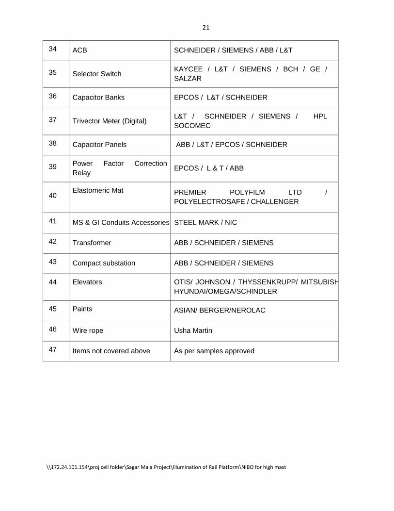
34 ACB SCHNEIDER / SIEMENS / ABB / L&T
35 Selector Switch KAYCEE / L&T / SIEMENS / BCH / GE /
SALZAR
36 Capacitor Banks EPCOS / L&T / SCHNEIDER
37 Trivector Meter (Digital) L&T / SCHNEIDER / SIEMENS / HPL
SOCOMEC
38 Capacitor Panels ABB / L&T / EPCOS / SCHNEIDER
39 Power Factor Correction
Relay EPCOS / L & T / ABB
40 Elastomeric Mat
PREMIER POLYFILM LTD /
POLYELECTROSAFE / CHALLENGER
41 MS & GI Conduits Accessories STEEL MARK / NIC
42 Transformer ABB / SCHNEIDER / SIEMENS
43 Compact substation ABB / SCHNEIDER / SIEMENS
44 Elevators OTIS/ JOHNSON / THYSSENKRUPP/ MITSUBISHI /
HYUNDAI/OMEGA/SCHINDLER
45 Paints ASIAN/ BERGER/NEROLAC
46 Wire rope Usha Martin
47 Items not covered above As per samples approved

22
\\172.24.101.154\proj cell folder\Sagar Mala Project\Illumination of Rail Platform\NIBO for high mast
BILL OF QUANTITIES
Name of Work: Supply, Installation ,Testing and Commissioning of 30 mtr High
Mast at Railway Platform / Yard at MPT
Sr.
No. Description of Work Unit Qty
Rate (Rs.) Amount
(Rs.) In Fig. In
Words
1 30 Mtr. High Mast
Design, Manufacturing, Supply ,
Installation, Testing and Commissioning
of 30 Mtrs. High mast complete with all
relevant accessories as per Technical
Specification.
i) Supply No. 3
ii) Refurbishing of highmast with all
accessories such as head frame, lantern
carriage, luminaire arm assembly,
suspension wires, compensating discs,
double winch drum, electrical hoist
cables, power tool, etc. as per Technical
Specification. No 3
iii) Installation, Testing and Commissioning No. 6
2 Load Point Panel
Design, Supply, Installation, Testing and
Commissioning of Load Point Panel for
Outdoor type, dust, vermin weather proof
fabricated from SS316 grade sheet of
2mm thick, suitable angled and flat etc.
and as per Technical Specification.
i) Supply No. 2
ii) Installation, Testing and Commissioning No. 2

23
\\172.24.101.154\proj cell folder\Sagar Mala Project\Illumination of Rail Platform\NIBO for high mast
3 Feedar Pillar
Design, Supply, Installation, Testing and
Commissioning of Feeder Piller for 30
Mtr. High Masts for Outdoor type, dust,
vermin weather proof fabricated from
SS316 grade sheet of 2mm thick, suitable
angled and flat etc. and as per Technical
Specification.
i) Supply No. 6
ii) Installation, Testing and Commissioning No. 6
4 Luminaries & Lamps
Supply, Installation, testing and
commissioning of following HPSV
luminaries with complete accessories
including lamps and as per Technical
Specification.
i) Supply of
a) 1 X 400W HPSV with SON-T lamps No. 36
b) 2 X 400W HPSV with SON-T lamps No. 48
c) 1 X 1000W HPSV with SON-T lamps No. 12
ii)
Installation, Testing and
Commissioning of
a) 1 X 400W HPSV with SON-T lamps No. 36
b) 2 X 400W HPSV with SON-T lamps No. 48
c) 1 X 1000W HPSV with SON-T lamps No. 12
5 LT XLPE Cable
Supply of following size of LT, 1.1KV,
XLPE Alumiunm armoured cable
conforming to IS 7098 (Part - II) and as
per Technical Specification.
i) Supply of
a) 3 1/2 C X 120 sq.mm. Mtr. 800
b) 3 1/2 C X 25 sq.mm. Mtr. 500
24
\\172.24.101.154\proj cell folder\Sagar Mala Project\Illumination of Rail Platform\NIBO for high mast
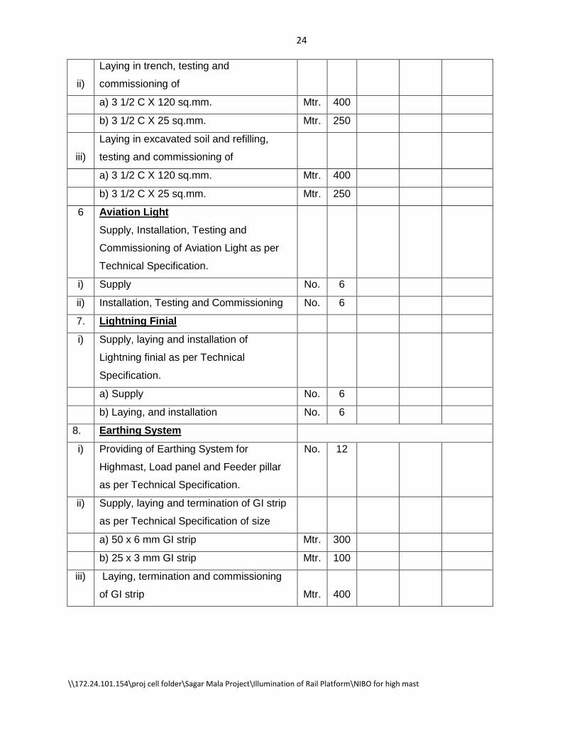
ii)
Laying in trench, testing and
commissioning of
a) 3 1/2 C X 120 sq.mm. Mtr. 400
b) 3 1/2 C X 25 sq.mm. Mtr. 250
iii)
Laying in excavated soil and refilling,
testing and commissioning of
a) 3 1/2 C X 120 sq.mm. Mtr. 400
b) 3 1/2 C X 25 sq.mm. Mtr. 250
6 Aviation Light
Supply, Installation, Testing and
Commissioning of Aviation Light as per
Technical Specification.
i) Supply No. 6
ii) Installation, Testing and Commissioning No. 6
7. Lightning Finial
i) Supply, laying and installation of
Lightning finial as per Technical
Specification.
a) Supply No. 6
b) Laying, and installation No. 6
8. Earthing System
i) Providing of Earthing System for
Highmast, Load panel and Feeder pillar
as per Technical Specification.
No. 12
ii) Supply, laying and termination of GI strip
as per Technical Specification of size
a) 50 x 6 mm GI strip Mtr. 300
b) 25 x 3 mm GI strip Mtr. 100
iii) Laying, termination and commissioning
of GI strip Mtr. 400

25
\\172.24.101.154\proj cell folder\Sagar Mala Project\Illumination of Rail Platform\NIBO for high mast
9 Protection Guard
Design, supply, Fabrication and erection
of protection guard having the height of
1.5 Mtr. Above the Ground Level
fabricated from main horizontal and
vertical members of MS angle of Size
75X75X10mm with cross
bracing including necessary foundation
work as per Technical Specification.
LS 6
10 Dismantling, shifting of exsiting 30 Mtr.
Highmasts with complete accessories
including light fixtures as per Technical
Specification.
No. 3
Total


![Eindhoven University of Technology MASTER A low cost ...1987, An electronic ballast fora white-son lamp: The lamp is a high-pressure sodium lamp [2] with 32V steady-state voltage.](https://static.fdocuments.in/doc/165x107/60d7675c3712be745b46ba70/eindhoven-university-of-technology-master-a-low-cost-1987-an-electronic-ballast.jpg)