MORENO MASTER DRAINAGE PLAN - rcflood.orgrcflood.org/Downloads/Master Drainage Plans/Updated/Zone...
35
RIVERSIDE COUNTY FLOOD CONTROL AND WATER CONSERVATION DISTRICT Riverside, California MORENO MASTER DRAINAGE PLAN ZONE FOUR Original Plan – September 1980 WARREN D. WILLIAMS Revision No. 2 – April 2015 General Manager-Chief Engineer
Transcript of MORENO MASTER DRAINAGE PLAN - rcflood.orgrcflood.org/Downloads/Master Drainage Plans/Updated/Zone...

RIVERSIDE COUNTY FLOOD CONTROL AND WATER CONSERVATION DISTRICT
Riverside, California
MORENO
MASTER DRAINAGE PLAN
ZONE FOUR Original Plan – September 1980 WARREN D. WILLIAMS Revision No. 2 – April 2015 General Manager-Chief Engineer

MORENO MASTER DRAINAGE PLAN
(Revision No. 2)
TABLE OF CONTENTS Page
SECTION I - PURPOSE ..................................................................................................................... 1
SECTION II - SCOPE ......................................................................................................................... 1
SECTION III - GENERAL DISCUSSION ......................................................................................... 2
SECTION IV – MASTER DRAINAGE PLAN OBJECTIVES .......................................................... 2
SECTION V - HYDROLOGY ............................................................................................................ 3
SECTION VI – EXISTING FACILITIES ........................................................................................... 4
SECTION VII – FACILITY SIZING CRITERIA ............................................................................... 5
SECTION VIII – PROPOSED IMPROVEMENTS ............................................................................ 6
SECTION IX - ALTERNATIVES ..................................................................................................... 13
SECTION X – ESTIMATED COST .................................................................................................. 14
SECTION XI - CONCLUSIONS ....................................................................................................... 17
SECTION XII - RECCOMENDATIONS .......................................................................................... 17
TABLES
TABLE 1 - NOAA Atlas 14 Point Rainfall Values ............................................................................. 3
TABLE 2 - Existing Facilities ............................................................................................................. 4
TABLE 3 - Cost Summary.................................................................................................................. 14
TABLE 4 - Alternatives: Basin Footprint Summary .......................................................................... 21
TABLE 5 - Decision Matrix ............................................................................................................... 24
APPENDIX
ALTERNATIVES ANALYSIS ............................................................................................... APPENDIX A
EXHIBIT 1 - Alternative 1 ...................................................................................................... APPENDIX B
EXHIBIT 2A - Alternative 2A ................................................................................................. APPENDIX B
EXHIBIT 2B - Alternative 2B ................................................................................................. APPENDIX B
EXHIBIT 3 - Alternative 3 ...................................................................................................... APPENDIX B
EXHIBIT 4 - Alternative 4 ...................................................................................................... APPENDIX B
MAP
Master Drainage Plan ............................................................................................... INSIDE BACK COVER
-1-
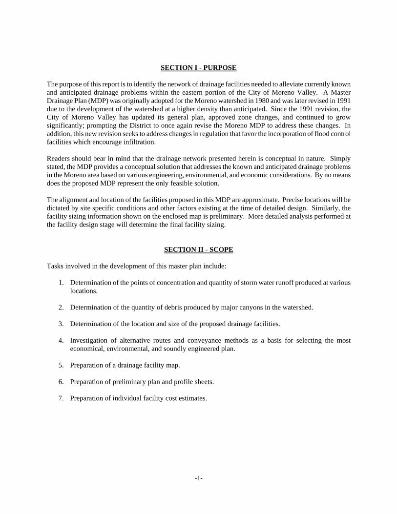
SECTION I - PURPOSE The purpose of this report is to identify the network of drainage facilities needed to alleviate currently known and anticipated drainage problems within the eastern portion of the City of Moreno Valley. A Master Drainage Plan (MDP) was originally adopted for the Moreno watershed in 1980 and was later revised in 1991 due to the development of the watershed at a higher density than anticipated. Since the 1991 revision, the City of Moreno Valley has updated its general plan, approved zone changes, and continued to grow significantly; prompting the District to once again revise the Moreno MDP to address these changes. In addition, this new revision seeks to address changes in regulation that favor the incorporation of flood control facilities which encourage infiltration. Readers should bear in mind that the drainage network presented herein is conceptual in nature. Simply stated, the MDP provides a conceptual solution that addresses the known and anticipated drainage problems in the Moreno area based on various engineering, environmental, and economic considerations. By no means does the proposed MDP represent the only feasible solution. The alignment and location of the facilities proposed in this MDP are approximate. Precise locations will be dictated by site specific conditions and other factors existing at the time of detailed design. Similarly, the facility sizing information shown on the enclosed map is preliminary. More detailed analysis performed at the facility design stage will determine the final facility sizing.
SECTION II - SCOPE Tasks involved in the development of this master plan include:
1. Determination of the points of concentration and quantity of storm water runoff produced at various locations.
2. Determination of the quantity of debris produced by major canyons in the watershed.
3. Determination of the location and size of the proposed drainage facilities.
4. Investigation of alternative routes and conveyance methods as a basis for selecting the most economical, environmental, and soundly engineered plan.
5. Preparation of a drainage facility map.
6. Preparation of preliminary plan and profile sheets.
7. Preparation of individual facility cost estimates.
-2-
SECTION III – GENERAL DISCUSSION
The Moreno MDP encompasses a portion of the City of Moreno Valley and surrounding Riverside County lands. The watershed is generally bounded by Lasselle Street on the west, Theodore Street on the east, the Badlands on the north, and the city boundary on the south. The proposed drainage plan involves the construction of detention basins, debris basins, open channels, and a network of underground storm drains. The drainage system will collect local urban runoff and transport the flows through this developing community to an outlet at the upper terminus of the Kitching Street Channel. The revision presented here is a re-evaluation and expansion of the 1991 Moreno MDP Revision (Adopted MDP). The proposed plan shall supersede all past plans and reports. The plan presented herein will provide flood protection from the 100-year flood to the community when implemented, serve as a guide for the long term construction scheduling of the primary drainage facilities, and serve the basis for revising the existing Moreno Area Drainage Plan (ADP). The plan will also act as a planning guide for the location and sizing of local drainage facilities to be constructed by developers and others within the area.
SECTION IV – MASTER DRAINAGE PLAN OBJECTIVES The following objectives were established for the Moreno Master Drainage Plan Revision:
1. Revise the Moreno MDP to provide a drainage plan which supports the existing and proposed land use as set forth in the “Riverside County General Plan” updated in 2008, “City of Moreno Valley General Plan” updated in July 2006, and any proposed amendments thereto.
2. The fully implemented plan should, in conjunction with ultimate street improvements for the area within the boundaries of the Moreno MDP, contain the 100-year frequency flows and alleviate the primary sources of flooding.
3. Identify preferred facility alignments, sizing, and right-of-way required for the future construction of
MDP facilities to protect existing and future development.
4. Identify the most economical combination of facilities considering right-of-way acquisition, construction, and maintenance costs.
5. Develop a plan which, when implemented, will result in the elimination of FEMA designated Special
Flood Hazard Areas within the boundaries of the Moreno MDP.
6. Revise the Moreno MDP to minimize major diversions and perpetuate the natural drainage pattern of the area to the maximum extent practicable.
7. Where feasible, incorporate facilities which encourage infiltration.
8. Minimize environmental impacts to the maximum extent practicable.

-3-
SECTION V – HYDROLOGY
Revision Studies: This section outlines methodology, assumptions, and rainfall values used for new studies within the drainage area boundary for this MDP revision. The areas restudied were those tributary to Line F north of Cactus Avenue, areas tributary to Quincy Channel (Line G), and areas north of California State Route 60 (SR 60) not tributary to Nason Basin. New studies for the western portion of the plan (west of the Line G system) were not performed during the revision since many of the facilities here have already been constructed and were designed based on the Adopted MDP flow rates and alignments (see Previous Studies section below for additional information). Two methods were used to develop the hydrology for this MDP revision: the Rational Method and the Synthetic Unit Hydrograph Method. The Rational Method was used to determine the peak discharges (cubic feet per second) generated from smaller watersheds less than 300 to 500 acres in size. For watersheds larger than 500 acres, the Synthetic Unit Hydrograph Method was used. To account for the attenuating effects of channel and basin storage, the Convex Routing Method and Modified Puls Methods were used, respectively. Methodology and supportive data for both the Rational and Synthetic Unit Hydrograph Methods may be found in the Riverside County Flood Control and Water Conservation District Hydrology Manual, dated April 1978 (District Hydrology Manual). Future land use assumptions were based on the following:
"The City of Moreno Valley General Plan," updated July 2006 “The Riverside County General Plan,” updated December 2008 Potential changes to areas currently zoned under the “Moreno Highlands Specific Plan,” adopted in
1992. NOAA Atlas 14 Version 4 rainfall values were used in the hydrology calculations performed for this MDP revision. The rainfall frequencies examined were the 2-year (50% annual chance) and the 100-year (1% annual chance) recurrence intervals with 1, 3, 6 and 24 hour durations. The calculated slope of the intensity-duration curve is 0.577. Table 1 highlights the NOAA Atlas 14 Version 4 area weighted point rainfall values used to develop the revision studies:
TABLE 1 – NOAA Atlas 14 Point Rainfall Values Storm Frequency and Duration Area Weighted Point Rainfall (Inches)
2 Year – 1 Hour 0.52
2 Year – 3 Hour 0.90
2 Year – 6 Hour 1.29
2 Year – 24 Hour 2.29
100 Year – 1 Hour 1.57
100 Year – 3 Hour 2.42
100 Year – 6 Hour 3.38
100 Year – 24 Hour 6.43

-4-
Previous Studies: Line K System – The flow rates for the Line K system have remained the same as in the Adopted Plan. No changes were proposed to the alignment and no major changes in land use have occurred. Hydrology backup calculations for this line are from studies performed for the Adopted MDP. Line K was sized in these studies using NOAA Atlas 2 rainfall values. Line H System – Hydrology for this system comes from the approved hydrology study for Tract 31128 and 31129 performed by PHB & Associates, Inc. This study reflects changes to the Adopted MDP alignment. This study uses NOAA Atlas 2 rainfall values.
SECTION VI – EXISTING FACILITIES In preparing this master drainage plan revision an inventory of known existing facilities was made and is summarized in Table 2. Those facilities serving as part of revised Moreno MDP drainage system are shown on the updated Moreno MDP map.
TABLE 2 – Existing Facilities
Facility Drawing Number Maintenance
Line A 4-473 RCFC
Line D 4-1007 RCFC
Line D-5 4-1007 RCFC
Line D-6 4-1007 RCFC
Line F 4-502,4-5271 4-1007, 4-912(Future RCFC) RCFC
Line F-2 4-491,4-847 RCFC
Line F-3 4-501, 4-506 RCFC
Line F-4 4-501 RCFC
Line F-5 4-570 RCFC
Line F-6 4-528 RCFC
Line F-7 4-501 RCFC
Line F-8 4-509 RCFC
Line F-9 - MV
Line F-9 4-1007 RCFC
Line F-11 4-847 RCFC
Line F-12 4-847 RCFC
Line F-14 4-719 RCFC
Line G 4-526, 4-886 RCFC
Line G-5 (Auto Mall Dr Lateral) 4-526 MV
Line G-7 4-879 RCFC
Line H-1 4-885 RCFC
Line H-2 4-875 RCFC
Line H-3 - MV

-5-
Facility Drawing Number Maintenance
Line H-6 4-875 RCFC
Line H-7 4-867 RCFC
Line H-8 4-875 RCFC
Line H-9 4-834 RCFC
Line I 4-583, 4-647, 4-738, 7-405, 4-904, 4-905 RCFC
Line J 4-858, (4-955 Future RCFC) RCFC
Line J-2 4-858 RCFC
Line J-3 4-858 RCFC
Line J-4 4-858 RCFC
Line J-5 4-858 MV
Line J-6 4-858 RCFC
Line J-9 4-1027 (Future RCFC)
Line J-10 4-646, 4-647 RCFC
Line K-1 - MV
Line K-3 - MV
Moreno Cold Creek SD - Line A 4-929 RCFC
SECTION VII – FACILITY SIZING CRITERIA Underground Storm Drains The underground facilities proposed in this MDP are located within existing or assumed future right-of-way, whenever possible, and consists of reinforced concrete pipe (RCP) ranging in size from 27 inches to 108 inches in diameter and reinforced concrete boxes (RCB) ranging in dimensions from 7’W x 7’D to 10’W x 8’D. Underground storm drain facilities were sized based on their full flow capacity. Open Channels The open channel facilities proposed are generally located along existing drainage ditches, washes, and where the proposed construction of the channel would have minimal impacts on adjacent properties. The open channels serve as flow conveyors and provide outlets for underground facilities proposed in the plan. Two types of open channels are proposed in this MDP, concrete lined channels and earthen bottomed channels with rock lined side slopes (unlined). The hydraulic sizing of open channels is based on normal depth calculations. The right-of-way requirements for both lined and unlined facilities include the full channel width, maintenance access roads, as well as a 5 foot buffer on either side for anticipated cut and fill. Channels with top widths of less than 20 feet require one 15 foot maintenance access road; where the top width exceeds 20 feet, two maintenance access roads are necessary. Detention Basins The detention basins proposed in this MDP are located upstream existing facilities with limited hydraulic capacity (e.g. freeway culverts, Line F). The purpose of the detention basin is to attenuate peak flow rates to match the capacity of downstream existing facilities through the use of temporary detention storage. It should be noted that the detention basins proposed in this plan are sized for the 1% annual chance ("100-year" storm) event. Flows exceeding the design capacity of the basin would pass over an emergency spillway in flow patterns approximating present conditions. Debris Basins

-6-
Debris basins are proposed in watersheds where significant amount of debris would be expected and are generally located upstream of the proposed facilities to capture the debris before it enters the downstream conveyance system. The proposed debris basins were sized using the Tatum Method by the U.S. Army Corps of Engineers Los Angeles District, dated 1963.
SECTION VIII – PROPOSED IMPROVEMENTS The improvements proposed in this MDP are shown on the enclosed map found at the back of this report. Supporting data for proposed facilities is available at the Riverside County Flood Control and Water Conservation District's Office. The design engineer should be aware that a detailed utility search was not completed. This means that, while the major known facilities were considered during the development of this MDP, a more thorough search may reveal additional or newly placed utilities that may necessitate minor alignment and size changes, or utility relocations during final design. Line A – Line A begins approximately 300 feet west of the intersection of Locust Avenue and Quincy Street as a 4.5 foot deep concrete lined trapezoidal channel with side slopes of 1.5:1 and a base width of 6 feet. The channel extends southerly and connects to an existing section of Line A which continues southerly and southeasterly to a confluence point with the proposed Line A-1 just south of Kalmia Street. At the confluence point Line A transitions into a 8’W x 7’D RCB and continues southerly. The RCB then transitions into a 9’W x 7’D and continues southerly to an outlet into the proposed Sinclair Basin just north of California State Route 60 (SR 60). Line A-1 – Line A-1 begins at a point approximately 1,315 feet north and 235 feet east of the intersection of Locust Avenue and Quincy Street as a 72-inch RCP. The 72-inch RCP extends westerly to Quincy Street and southerly in Quincy Street. At Kalmia Avenue, the 72-inch RCP transitions into a 78-inch RCP until the confluence with Line A. Line A-2 – Line A-2 begins approximately 650 feet east of the intersection of Locust Avenue and Quincy Street as a 42-inch RCP. The 42-inch RCP extends westerly until the confluence with the proposed Line A-1. Line A-3 – Line A-3 begins at the intersection of Edmonson Avenue and Kalmia Avenue as a 42-inch RCP. The 42-inch RCP extends easterly in Kalmia Avenue until the confluence with an existing portion of Line A. Line A-6 – Line A-6 begins at a point approximately 1,300 feet west and 1,300 feet north of the intersection of Quincy Street and Ironwood Avenue as a 36-inch RCP. The 36-inch RCP extends southerly and transitions into a 42-inch and then a 48-inch RCP. At Hemlock Avenue the 48-inch RCP continues easterly and transitions into a 78-inch RCP, then into a 84-inch RCP, and finally into a 7’W x 7’D RCB until the confluence with Line A. Line A-7 – The upstream origin of Line A-7 begins approximately 850 feet east of the intersection of Petit Street and Ironwood Avenue as a 42-inch RCP. The 42-inch RCP extends to the westerly until the confluence with line A-6. Line A-8 – Line A-8 begins approximately at the intersection of Hinson Street and Hemlock Avenue as a 42-inch RCP. The 42-inch RCP extends easterly and transitions into a 54-inch RCP until the confluence with Line A-6.

-7-
Line B – Line B begins approximately 1,200 feet southeast of the intersection of Redlands Boulevard and Highland Boulevard as a 66-inch RCP. The 66-inch RCP extends easterly for 720 feet and then transitions into an 8’W x 7’D RCB following Highland Boulevard southeasterly for 1850 feet. The facility then extends southerly to Ironwood Avenue. From here the facility transitions into an 8’W x 8’D RCB extending easterly for approximately 740 feet before heading southerly for 1,310 feet to the confluence with Line C. At the confluence, the facility transitions into a 10’W x 8’D RCB which continues southerly to an outlet into the proposed Sinclair Basin just North of SR 60. Line B-1 – Line B-1 begins approximately 730 feet west of the intersection of Theodore Street and Ironwood Avenue along Ironwood Avenue Street as a 78-inch RCP. The 78-inch RCP extends westerly along Ironwood Avenue until the confluence with Line B. Line B-2 – Line B-2 begins approximately 850 feet west of the intersection of Juniper Avenue and Highland Boulevard as a 54-inch RCP. The 54-inch RCP extends easterly in Juniper Avenue until the confluence with Line B. Line B-3 – Line B-3 begins approximately 2,110 feet east of the intersection of Redlands Boulevard and Ironwood Avenue as a 42-inch RCP. The 42-inch RCP extends easterly in Ironwood Avenue until the confluence with Line B. Line C – The upstream origin of Line C begins at the outlet of the proposed Ironwood Debris Basin as a 66-inch RCP. The 66-inch RCP extends southerly in Theodore Street for 930 feet before transitioning into a 78-inch RCP and heading easterly until the confluence with Line B. Line D-1 – Line D-1 begins approximately 820 feet west of the intersection of Locust Avenue and Redlands Boulevard as a 42-inch RCP. The 42-inch RCP extends easterly in Locust Avenue and transitions into a 48-inch RCP until the confluence with Redlands Boulevard. Line D-2 – Line D-2 begins approximately 1,750 feet west of the intersection of Kalmia Avenue and Redlands Boulevard as a 42-inch RCP. The 42-inch RCP extends easterly and transitions into a 48-inch RCP, to a 60-inch RCP, and finally to a 66-inch RCP until the confluence with Line D-5. Line D-3 – Line D-3 begins approximately 1,750 feet west of the intersection of Juniper Avenue and Redlands Boulevard as a 42-inch RCP. The 42-inch RCP extends easterly and transitions into a 48-inch RCP, to a 60-inch RCP, and finally to a 66-inch RCP until the confluence with Line D-5. Line D-4 – Line D-4 begins approximately 670 feet east of the intersection of Juniper Avenue and Redlands Boulevard as a 42-inch RCP. The 42-inch RCP extends westerly until the confluence with Line D-5. Line D-5 – Line D-5 begins at the intersection of Locust Avenue and Redlands Boulevard as a 48-inch RCP. The 48-inch RCP extends southerly in Redlands Boulevard, transitioning into a 66-inch RCP until Ironwood Avenue where the 66-inch RCP transitions into a 90-inch RCP and turns easterly for approximately 1,310 feet. At this point the 90-inch RCP turns southerly for 1,300 feet, easterly for 690 feet, and finally southerly for 530 feet to an outlet into the proposed Sinclair Basin just north of SR 60. Line D-7 – Line D-7 begins approximately 1,750 feet west of the intersection of Ironwood Avenue and Redlands Boulevard as a 36-inch RCP. The 36-inch RCP extends easterly and transitions into a 48-inch RCP, to a 60-inch RCP, and finally to a 66-inch RCP until the confluence with Line D-5. Line D-8 – The upstream origin of Line D-8 begins at a point approximately 1,300 feet south and 240 feet

-8-
east of the intersection of Ironwood Avenue and Redlands Boulevard as a 42-inch RCP. From there the 42-inch RCP extends easterly and transitions into a 54-inch RCP until the confluence with Line D-5. Line D-9 – Line D-9 begins at a point approximately 1,640 feet east of the intersection of Redlands Boulevard and Ironwood Avenue as a 36-inch RCP. The 36-inch RCP extends westerly until the confluence with Line D-5. Line E-1 – Line E-1 begins at a point approximately 2,600 feet south of State Route 60 and 250 feet east of Redlands Boulevard as a 36-inch RCP. The 36-inch pipe extends easterly and transitions into a 54-inch RCP and then to a 66-inch RCP until the confluence with Line F. Line E-2 – Line E-2 begins at a point approximately 2,600 feet south of State Route 60 and 1,750 feet west of the Theodore Street as a 36-inch RCP. The 36-inch RCP extends westerly and transitions into a 54-inch RCP, to a 60-inch RCP, and then finally to a 66-inch RCP until the confluence with Line F. Line E-3 – Line E-3 begins at a point approximately 250 feet east of the intersection of Redlands Boulevard and Dracaea Avenue as a 42-inch RCP. The 42-inch RCP extends easterly and transitions into a 54-inch RCP, to a 66-inch RCP, and finally into a 72-inch RCP until the confluence with Line F. Line E-4 – Line E-4 begins at a point approximately 2,000 feet west of the intersection of Theodore Street and Dracaea Avenue as a 48-inch RCP. The 48-inch RCP extends westerly and transitions into a 60-inch RCP and finally to a 66-inch RCP until the confluence with Line F. Line E-5 – Line E-5 begins at a point approximately 250 feet east of the intersection of Redlands Boulevard and Cottonwood Avenue as a 42-inch RCP. The 42-inch RCP extends easterly and transitions into a 48-inch RCP, to a 66-inch RCP, and finally to a 72-inch RCP until the confluence with Line F. Line E-6 – Line E-6 begins at a point approximately 1,975 feet west of the intersection of Theodore Street and Cottonwood Avenue as a 48-inch RCP. The 48-inch RCP extends westerly and transitions into a 60-inch RCP and finally into a 66-inch RCP until the confluence with Line F. Line E-7 – Line E-7 begins at a point approximately 275 feet east of the intersection of Redlands Boulevard and Bay Avenue as a 42-inch RCP. The 42-inch RCP extends easterly and transitions into a 60-inch RCP, to a 66-inch RCP, and finally to a 72-inch RCP until the confluence with Line F. Line E-8 – Line E-8 begins at a point approximately 1,975 feet west of the intersection of Theodore Street and Bay Avenue as a 48-inch RCP. The 48-inch RCP extends westerly and transitions into a 54-inch RCP and finally into a 66-inch RCP until the confluence with Line F. Line E-10 – Line E-10 begins at a point approximately 1,975 feet east of the intersection of Merwin Street and Alessandro Boulevard as a 36-inch RCP. The 36-inch RCP transitions into a 54-inch RCP and finally into a 60-inch RCP until the confluence with Line F. Line F – Line F begins approximately 1,350 feet south of SR 60 and 1,600 feet east of Redlands Boulevard as an earthen bottom trapezoidal channel with rock-lined side slopes. The earthen channel runs southerly to Alessandro Boulevard and southwesterly from below Alessandro Boulevard to Redlands Boulevard where it connects to an existing box culvert in Redlands Boulevard. Typical channel sections in this reach have a depth of 8 feet, base widths of 6 to 38 feet, and side slopes of 2:1. There is another proposed section of Line F which begins approximately 500 feet north of the intersection of Oliver Street and John F. Kennedy Drive running southwesterly for 850 feet before connecting to existing Line F.

-9-
Line F-2 – Line F-2 begins at the intersection of Ironwood Ave. and Redlands Boulevard as a 54-inch RCP and connects to Line F-15. The 54-inch RCP extends southerly to an existing 60-inch Caltrans culvert which extends the pipe to the south side of the State Route 60 Redlands Boulevard off ramp. Line F-2 resumes from the downstream terminus of the existing culvert as a 66-inch RCP which continues southerly transitioning to a 72-inch RCP, to a 78-inch RCP, to a 84-inch RCP, to a 90-inch RCP, to a 96-inch RCP, and finally into a 108-inch RCP until an outlet into the proposed Cactus Basin. Line F-5 – Line F-5 begins approximately 100 feet south of the intersection of Oliver Street and John F. Kennedy Drive at the downstream terminus of an existing portion of Line F-5 as a double 8’W x 4’D RCB. The RCB extends westerly for 700 feet to the confluence with existing Line F. Line F-13 – Line F-13 begins at a point approximately 1,330 feet north of the intersection of Moreno Beach Drive and Cactus Boulevard as a 33-inch RCP. The 33-inch RCP extends southerly and transitions into a 39-inch RCP until the confluence with existing Line F-4. Line F-15 – Line F-15 begins at a point approximately 1,310 feet south and 1,750 feet west of the intersection of Redlands Boulevard and Ironwood Avenue as a 36-inch RCP. The 36-inch RCP extends easterly and transitions into a 48-inch RCP and then to a 54-inch RCP until the confluence with Line F-2 at Redlands Boulevard. Line F-16 – Line F-16 begins at a point approximately 1,350 feet south of SR 60 and 2,250 feet west of the Redlands Boulevard as a 42-inich RCP. The 42-inch RCP extends easterly and transitions into a 48-inch RCP, to a 54-inch RCP and finally to a 72-inch RCP until the confluence with Line F-2. Line F-17 – Line F-17 begins at a point approximately 2,630 feet south of SR 60 and 2,250 feet west of the Redlands Boulevard as a 42-inch RCP. From there the 42-inch RCP extends easterly and transitions into a 48-inch RCP, to a 54-inch RCP, and finally to a 60-inch RCP until the confluence with Line F-2. Line F-18 – Line F-18 begins at a point approximately 1,000 feet east of the intersection of Redlands Boulevard and Alessandro Boulevard as a 48-inch RCP. The 48-inch RCP extends westerly and transitions into a 60-inch RCP until the confluence with Line F-2. Line F-19 – Line F-19 begins at a point approximately 500 feet east of the intersection of Redlands Boulevard and Brodiaea Avenue as a 60-inch RCP. The 60-inch RCP extends westerly until the confluence with Line F-2. Line G – Line G begins approximately 850 feet south and 450 feet east of the intersection of Eucalyptus Avenue and Auto Mall Drive as an earthen bottom trapezoidal channel with rock-lined side slopes. The earthen channel runs southeasterly until a confluence with proposed Line G-7, approximately 400 feet north of the intersection of Cottonwood Avenue and Quincy Street. Line G continues southerly, parallel to Quincy Street, until an outlet into existing Line F. Typical channel sections in this reach have depths of 6 to 8 feet, base widths of 6 to 16 feet, and side slopes of 2:1. Line G-1 – Line G-1 begins at a point approximately 1,200 feet north of SR 60 and 250 feet east of the Moreno Beach Drive as a 42-inch RCP. The 42-inch RCP extends easterly until the confluence with Line G-4. Line G-2 – Line G-2 begins at the intersection of Hemlock Avenue and Petit Street as a 42-inch RCP. The 42-inch RCP extends westerly and transitions into a 54-inch RCP until the confluence with Line G-4.

-10-
Line G-3 – Line G-3 begins at a point approximately 1,975 feet east of Moreno Beach Drive immediately north of SR 60 as a concrete lined rectangular channel. The channel extends westerly until the confluence with Line G-4. Typical sections for this channel have a depth of 6.5 feet and a base width of 10 feet. Line G-4 – Line G-4 begins at a point approximately 1,200 feet north of SR 60 and 500 feet east of Moreno Beach Drive as a 54-inch RCP. The 54-inch RCP extends southerly until it transitions and connects with the existing Caltrans culvert crossing under SR 60. Line G-7 –Line G-7 begins at a point approximately 2,600 feet west of Redlands Boulevard, just south of SR 60, as an earthen bottom trapezoidal channel with rock-lined side slopes. The channel extends southerly until the confluence with Line G approximately 400 feet north of the intersection of Quincy Street and Cottonwood Avenue. Typical sections for this channel have a depth of 5 feet, base widths of 5 feet, and side slopes of 2:1. Line G-8 – Line G-8 begins at a point approximately 500 feet east of the intersection of Quincy Street and Bay Avenue as a 48-inch RCP. The 48-inch RCP extends westerly until the confluence with Line G. Line G-9 – Line G-9 begins at a point approximately 1,300 feet east of the intersection of Quincy Street and Alessandro Avenue as a 48-inch RCP. The 48-inch RCP extends westerly and transitions to a 54-inch RCP and then to a 60-inch RCP until the confluence with Line G. Line G-10 – Line G-10 begins at a point approximately 750 feet east of the intersection of Quincy Street and Brodiaea Avenue as a 48-inch RCP. The 48-inch RCP extends easterly and transitions into a 54-inch RCP until the confluence with Line G. Line G-11 – Line G-11 begins at a point approximately 1,250 feet east of the intersection of Quincy Street and Cactus Avenue as a 36-inch RCP. From there the 36-inch RCP extends easterly and transitions into a 48-inch RCP and then to a 54-inch RCP until the confluence with Line G. Line H – Line H begins at the intersection of Mill Creek Road and Dracaea Avenue as a 42-inch RCP. The 42-inch RCP extends southerly to Cottonwood Avenue and then transitions to an 8.25’W x 5’D RCB which extends easterly in Cottonwood Avenue for 610 feet. Here the line runs southerly, transitions to a 75-inch RCP, to a 87-inch RCP, and continues southerly until Alessandro Boulevard. The 87-inch RCP then runs easterly in Alessandro Boulevard to Oliver Street, southerly in Oliver Street to Brodiaea Avenue, transitions to a 90-inch RCP, and continues southerly until the confluence with existing Line H at Cactus Avenue. Line H-1 – Line H-1 begins at a point approximately 1,020 feet east of the intersection of Moreno Beach Drive and Alessandro Boulevard at the downstream terminus of an existing portion of Line H-1 as a 48-inch RCP. The 48-inch RCP extends westerly and transitions into a 63-inch RCP and then to a 75-inch RCP until the confluence with Line H-2 and H-1a approximately 650 feet east of Pearl Lane. Line H-1a – Line H-1a begins at a point approximately 370 feet east of the intersection of Pearl Lane and Alessandro Boulevard as a 36-inch RCP. The 36-inch RCP extends easterly for 280 feet until the confluence with Line H-1 and H-2. Line H-2 – Line H-2 begins at the intersection of Bethany Road and Cottonwood Avenue as a 33-inch RCP. The 33-inch RCP extends southerly and transitions into a 39-inch RCP, to a 42-inch RCP, and finally to a 54-inch RCP until the confluence with Line H-1 at Alessandro Boulevard. Line H-2 then resumes from the confluence with Line H-1 and Line H-1a approximately 650 feet east of Pearl Lane on Alessandro Boulevard as an 84-inch RCP. The 84-inch RCP extends southerly until the confluence with an existing portion of Line H-2 at Brodiaea Avenue.

-11-
Line H-3 – Line H-3 begins at the intersection of Moreno Beach Drive and Cottonwood Avenue as a 42-inch RCP. The 42-inch RCP extends southerly and transitions into a 45-inch RCP until the confluence with Line H-1 at Alessandro Boulevard. Line H-4 – Line H-4 begins at a point approximately 1,550 feet east of the intersection of Nason Street and Bay Avenue as a 30-inch RCP. The 30-inch RCP extends westerly until the confluence with a Line H. Line H-5 – Line H-5 begins at a point approximately 1,350 feet west of the intersection of Olive Street and Brodiaea Avenue as a 30-inch RCP. The 30-inch RCP extends easterly and transitions into a 33-inch RCP until the confluence with Line H. Line H-5a – Line H-5a begins at a point approximately 290 feet east of the intersection of Olive Street and Brodiaea Avenue as a 36-inch RCP and extends westerly until the confluence with Line H. Line H-6 – Line H-6 begins at a point approximately 1,130 feet east of the intersection of Landon Road and Brodiaea Ave as a 36-inch RCP. From there the 36-inch extends westerly until the confluence with the existing portion of Line H-6 approximately 500 feet east of the intersection of Landon Road and Brodiaea Avenue. Line H-11 – Line H-11 begins at a point approximately 1,050 feet east of the intersection of Mill Creek Road and Dracaea Avenue at the terminus of Cold Creek Court Storm Drain Line A as a 60-inch RCP. The 60-inch RCP extends westerly for approximately 430 feet and then southerly until the confluence with line H at Cottonwood Avenue. Line J – Line J begins at the intersection of Morrison Street and Dracaea Avenue at the confluence with Line J-1 as a 48-inch RCP. The 48-inch RCP extends southerly until connecting to the existing portion of Line J at the intersection of Morrison Street and Rockport Drive. Line J then resumes at the intersection of Morrison Street and Alessandro Boulevard at the terminus of the existing underground Line J facility as a 78-inch RCP. The 78-inch RCP extends southerly and transitions into a 84-inch RCP until Cactus Avenue where it connects with an existing portion of Line J. Line J-1 – Line J-1 begins at a point approximately 1400 feet east of the intersection of Morrison Street and Dracaea Avenue as a 27-inch RCP. The 27-inch RCP extends westerly and transitions into a 39-inch RCP until the confluence with Line J at the intersection of Morrison Street and Dracaea Avenue. Line J-7 – Line J-7 begins at a point approximately 1350 feet south and 810 feet west of the intersection of Morrison Street and Alessandro Boulevard as a 24-inch RCP. The 24-inch RCP extends easterly until the confluence with Line J. Line J-8 – Line J-8 begins at a point approximately 1350 feet south and 1450 feet east of the intersection of Morrison Street and Alessandro Boulevard as a 39-inch RCP. The 39-inch RCP extends westerly and transitions into a 42-inch RCP until the confluence with Line J. Line K – Line K begins at the outlet of the proposed Reche Canyon Debris Basin, approximately 1500 feet east and 350 feet north of the intersection of Moreno Beach Drive and Locust Drive, as a concrete lined trapezoidal channel located on the southerly side of Reche Canyon Road. The channel extends southeasterly along Reche Canyon Road and easterly on Locust Avenue until the intersection with Moreno Beach Drive.

-12-
Typical channel sections for this reach have a depth of 7 feet, base widths of 10 feet, and side slopes of 1.5:1. From the intersection the channel transitions into a 14’W x 7’D RCB for 160 feet as it turns southerly along Moreno Beach Drive. The 14’W x 7’D RCB then transitions to a 9.5’W x 7’D RCB and continues southerly until a point approximately 300 feet north of Juniper Avenue. At this point Line K extends southeasterly, transitions to an earthen channel with rock-lined side slopes and continues past Ironwood Avenue until an outlet into the existing Nason Basin. Typical channel sections for this reach have a depth of 6 feet, bottom widths of 25 to 30 feet, and side slopes of 2:1. Line K-1 – Line K-1 begins at the intersection of Locust Avenue and Carrie Lane as a 42-inch RCP. The 42-inch RCP extends southerly to Kalmia Avenue, transitions to a 51-inch RCP as it extends westerly along Kalmia Avenue to Petit Street, and then southerly along Petit Street to the existing portion of Line K-1 approximately 665 feet north of the intersection of Petit Street and Juniper Avenue. Line K-1 then resumes at the downstream terminus of the existing Line K-1 facility at the intersection of Petit Street and Juniper Avenue as a 63-inch RCP. The 63-inch RCP extends southerly to Ironwood Avenue and then transitions to a 90-inch RCP as it extends westerly until the confluence with Line K. Line K-2 –Line K-2 begins at a point approximately 640 feet east of the intersection of Petit Street and Juniper Avenue as a 33-inch RCP. The 33-inch RCP extends westerly until the confluence with Line K-1. Line K-4 – Line K-4 begins at a point approximately 240 feet east of the intersection of Carrie Lane and Locust Avenue and extends westerly until the confluence with Line K-1. Reche Canyon Debris Basin – The Reche Canyon Debris Basin is located at a point approximately 1500 feet east and 350 feet north of the intersection of Locust Avenue and Moreno Beach Drive, just upstream of proposed Line K. The debris basin will require approximately 7.5 acres of right-of-way. Ironwood Debris Basin – The Ironwood Debris Basin is located just north of the intersection of Theodore Street Ironwood Avenue. The basin will require approximately 2.3 acres of right-of-way. Quincy Basin – The proposed Quincy Basin is located approximately 2600 feet west of Redlands Boulevard just north of SR 60. The basin has a right-of-way footprint of approximately 22.5 acres, a storage volume of 150 ac-ft, and an embankment height of approximately 12.5 feet. The basin outlet is proposed as one 60-inch RCP which will connect to an existing 60-inch CMP culvert crossing under SR 60. Cactus Basin – The proposed Cactus Basin is located between Redlands Boulevard and Wilmot Street just north of Cactus Avenue. The basin has a right-of-way footprint of approximately 21.7 acres, a storage volume of 100 ac-ft, and an embankment height of approximately 8 feet. The basin outlet utilizes the existing quadruple 8’W x 6’D RCB culverts under Cactus Avenue. Sinclair Basin – The proposed Sinclair Basin is located approximately 2600 feet east of Theodore Street just north of SR 60. The basin has a right-of-way footprint of approximately 25 acres, a storage volume of 170 acre-ft, and an embankment height of approximately 12.5 feet. The basin outlet is proposed as two 60-inch RCPs which connect to two existing 72-inch CMP culverts crossing under SR 60.

-13-
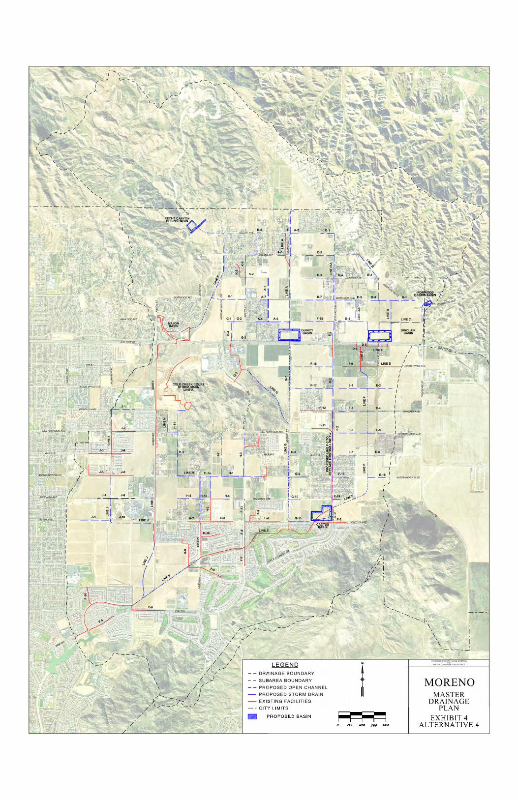
SECTION IX – ALTERNATIVES Given that this Master Drainage Plan (MDP) update is essentially a refinement of the adopted Moreno MDP, a relatively narrow range of alternatives was considered. Nonetheless, several alternatives were developed and evaluated against the project objectives established by the District and the City of Moreno Valley. The following section provides a brief summary of each alternative and indicates the preferred alternative. For the full alternative analysis and discussion, see appendix A. Alternatives Overview The following paragraphs describe the major components of each alternative developed during the MDP revision. Each description is supplemented with an exhibit in the appendix which displays the layout of facilities and basin locations. It should also be noted that, while the MDP update was being developed, the District and City mutually agreed that the existing Line F-2 storm drain facility, which is currently sized as a 10-year facility, would be reconstructed to provide 100-year flood capacity. Thus, the proposed reconstruction of Line F-2 was assumed to be a part of each alternative considered for the Moreno MDP Revision. Alternative 1: This alternative consists of the same types of facilities and alignments as in the Adopted MDP. Two detention basins are proposed along the Line F channel alignment: 1) Sinclair Basin just north of SR 60; and 2) Bay Avenue Basin located on the north side of Bay Avenue. In addition, Reche Canyon Debris Basin has been added to capture debris upstream of Line K. It should be noted that, similar to the Adopted MDP, this alternative proposes 1) concrete lining for all channel segments; and 2) makes use of the existing highway drainage culverts located under SR 60. See Exhibit 1 in the appendix for further detail. Alternative 2a and 2b: The principal difference between these two alternatives and Alternative 1 is the realignment of proposed facilities upstream of SR 60 in an effort to maintain the current natural drainage patterns within the upper watershed. This was accomplished by realigning the mainline facilities, specifically Line A, to convey flows from the foothills southerly to the existing culverts at SR 60 instead of diverting flows into the proposed Sinclair Basin. Both of these alternatives propose Lines F, G, and K as earthen channels with rock-lined side slopes (unlined channels) in place of the concrete lined channels proposed in Alternative 1. Reche Canyon Debris Basin has been included to capture debris upstream of Line K. Alternatives 2a and 2b differ from each other primarily in the size, number, and location of proposed detention basins. See Exhibit 2A and 2B for further detail. Alternative 3: This alternative retains the major realignment of Line A, as proposed in Alternatives 2a and 2b, but proposes three detention basins downstream of SR 60 in place of the various basins proposed in Alternatives 2a and 2b. This option would require the upsizing the existing highway drainage culverts under SR 60 to convey the 100-year flows to the proposed basin locations. The three detention basins proposed in Alternative 3 are: 1) Brodiaea Basin along Line G just north of Brodiaea Avenue; 2) Fir Basin just south of SR 60 along Line G-7; and 3) Cactus Basin at the downstream end of proposed Line F. This alternative also proposes Lines F, G, and K as earthen channels with rock-lined side slopes in place of the concrete lined channels proposed in Alternative 1. Reche Canyon Debris Basin has been included to capture debris upstream of Line K. See Exhibit 3 for further detail. Alternative 4 – Preferred Alternative: Similar to Alternatives 2a, 2b and 3, this alternative also calls for the realignment of proposed facilities upstream of SR 60 in an effort to maintain the current natural drainage patterns of the area. Alternative 4 proposes the implementation of three detention basins: 1) Quincy Basin located along Line A just north of the freeway; 2) Sinclair Basin located just north of SR 60 at the upstream end of Line F; and 3) Cactus Basin located at the confluence of Line F and Line F-2 just north of Cactus

-14-
Avenue. Similar to Alternative 2a, 2b, and 3, this alternative also proposes Lines F, G and K as earthen channels with rock-lined side slopes in place of the concrete lined channels proposed in Alternative 1. Reche Canyon Debris Basin has been included to capture the expected debris upstream of Line K, as well as Ironwood Debris Basin to capture expected debris upstream of Line C. See Exhibit 4 for further detail.
SECTION X – ESTIMATED COST A cost summary for the MDP facilities is shown in Table 3. Cost estimates were based on 2013 Planning Unit Cost Sheets and include construction, right-of-way, and 40% for engineering, administration, and environmental mitigation and contingencies. The costs estimates for the proposed facilities include the cost of manholes, catch basins and pipe installations. Manholes are located as necessary with a maximum spacing of 500 feet. Catch basins are not specifically located but the total number of lineal feet is included in the cost estimate. The cost for the open channel facilities includes the cost of access roads and right-of-way requirements. Channel access roads are assumed to be 15 feet wide and two (2) access roads were included where channel top widths exceed 20 feet. An additional 5 foot buffer has been included on either side of channel access roads for anticipated cut and fill. Detention basin costs include the cost of a 20 foot wide access road around the perimeter.
TABLE 3
MORENO MASTER DRAINAGE PLAN REVISION 2 COST SUMMARY
Facility Construction Cost Right-of-Way Cost Total Cost
Line A $4,941,000 $10,000 $4,951,000 Line A-1 $2,658,000 - $2,658,000 Line A-2 $302,000 - $302,000 Line A-3 $297,000 - $297,000 Line A-6 $2,366,000 - $2,366,000 Line A-7 $224,000 - $224,000 Line A-8 $447,000 - $447,000 Line B $7,967,000 - $7,967,000 Line B-1 $1,269,000 - $1,269,000 Line B-2 $482,000 - $482,000 Line B-3 $263,000 - $263,000 Line C $2,091,000 - $2,091,000 Line D-1 $404,000 - $404,000 Line D-2 $973,000 - $973,000 Line D-3 $973,000 - $973,000 Line D-4 $310,000 - $310,000 Line D-5 $6,014,000 - $6,014,000

-15-
Facility Construction Cost Right-of-Way Cost Total Cost Line D-7 $951,000 - $951,000 Line D-8 $538,000 - $538,000 Line D-9 $145,000 - $145,000 Line F $13,675,000 $1,055,000 $14,730,000 Line F-2 $8,804,000 - $8,804,000 Line F-5 $1,430,000 - $1,430,000 Line F-13 $613,000 - $613,000 Line F-15 $886,000 - $886,000 Line F-16 $1,401,000 - $1,401,000 Line F-17 $1,149,000 - $1,149,000 Line F-18 $588,000 - $588,000 Line F-19 $347,000 - $347,000 Line E-1 $885,000 - $885,000 Line E-2 $885,000 - $885,000 Line E-3 $1,092,000 - $1,092,000 Line E-4 $801,000 - $801,000 Line E-5 $1,052,000 - $1,052,000 Line E-6 $788,000 - $788,000 Line E-7 $1,109,000 - $1,109,000 Line E-8 $745,000 - $745,000 Line E-10 $624,000 - $624,000 Line G $10,121,000 $935,000 $11,056,000 Line G-1 $129,000 - $129,000 Line G-2 $431,000 - $431,000 Line G-3 $1,664,000 $50,000 $1,714,000 Line G-4 $617,000 - $617,000 Line G-7 $2,913,000 $305,000 $3,218,000 Line G-8 $264,000 $264,000 Line G-9 $735,000 - $735,000 Line G-10 $420,000 - $420,000 Line G-11 $647,000 - $647,000 Line H $7,367,000 - $7,367,000 Line H-1 $1,841,000 - $1,841,000 Line H-1a $115,000 - $115,000 Line H-2 $2,507,000 - $2,507,000 Line H-3 $1,251,000 - $1,251,000 Line H-4 $177,000 - $177,000 Line H-5 $525,000 - $525,000

-16-
Facility Construction Cost Right-of-Way Cost Total Cost Line H-5a $132,000 - $132,000 Line H-6 $278,000 - $278,000 Line H-11 $981,000 - $981,000 Line J $11,776,000 - $11,776,000 Line J-1 $591,000 - $591,000 Line J-7 $258,000 - $258,000 Line J-8 $682,000 - $682,000 Line K $9,816,000 $570,000 $10,386,000 Line K-1 $4,240,000 - $4,240,000 Line K-2 $283,000 - $283,000 Line K-4 $138,000 - $138,000 Cactus Basin $5,047,000 $3,300,000 $8,347,000 Sinclair Basin $6,014,000 $2,400,000 $8,414,000 Quincy Basin $5,174,000 $2,150,000 $7,324,000 Reche Canyon Debris Basin
$706,000 $713,000 $1,419,000
Ironwood Debris Basin
$197,000 $219,000 $416,000
Total $148,526,000 $11,707,000 $160,233,000 NOTE: Total Costs include 40% for Engineering, Administration, MSHCP Fee and Contingencies.
-17-
SECTION XI - CONCLUSIONS Based on the studies and investigations made for this report, it is concluded that:
1. The Moreno Valley area has experienced serious flooding problems in the past. The fully
implemented plan should, in conjunction with ultimate street improvements for the area within the boundaries of the Moreno MDP, contain the 100-year frequency flows and alleviate the primary sources of flooding.
2. The proposed plan addresses the denser development anticipated in the Moreno Valley area and
provides network of drainage facilities which, when implemented, will provide adequate flood protection to the community as development continues.
3. The proposed MDP lends itself to a staged construction as funds become available.
4. The total cost of the recommended improvements, including right-of-way, engineering, environmental mitigation, administration, and contingencies is estimated to be $160,233,000.
SECTION XII - RECOMMENDATIONS
It is recommended that:
1. The Moreno Master Drainage Plan revision, as set forth herein, be adopted by the City of Moreno Valley and the District’s Board of Supervisors.
2. The revisions to the Moreno Master Drainage Plan, as set forth herein, replace the Master Drainage Plan adopted in April 1991.
3. The revision to the Moreno Master Drainage Plan, as set forth herein, be used as a guide for all the
future developments in the study area and that such developments be required to conform to the Plan insofar as possible.
4. Right-of-way necessary for the implementation of the MDP be protected from encroachment.

-18-
APPENDIX A
-19-
ALTERNATIVES ANALYSIS
Alternatives Overview Given that this Master Drainage Plan (MDP) update is essentially a refinement of the adopted Moreno MDP, a relatively narrow range of alternatives was considered. Nonetheless, several alternatives were developed and evaluated against the project objectives established by the District and the City of Moreno Valley. This section provides a brief description of the major components of each alternative and indicates preferred alternative. Each description is supplemented with an exhibit in the appendix which displays the layout of facilities and basin locations. It should also be noted that, while the MDP update was being developed, the District and City mutually agreed that the existing Line F-2 storm drain facility, which is currently sized as a 10-year facility, would be reconstructed to provide 100-year flood capacity. Thus, the proposed reconstruction of Line F-2 was assumed to be a part of each alternative considered for the Moreno MDP Revision. Alternative 1: This alternative consists of the same types of facilities and alignments as in the currently adopted Moreno MDP (Adopted MDP). Two detention basins are proposed along the Line F channel alignment: 1) Sinclair Basin just north of California State Route 60 (SR 60); and 2) Bay Avenue Basin located on the north side of Bay Avenue. In addition, Reche Canyon Debris Basin has been added to capture debris upstream of Line K. It should be noted that, similar to the Adopted MDP, this alternative proposes 1) concrete lining for all channel segments; and 2) makes use of the existing highway drainage culverts located under SR 60. See Exhibit 1 in the appendix for further detail. Alternative 2a and 2b: The principal difference between these two alternatives and Alternative 1 is the realignment of proposed facilities upstream of SR 60 in an effort to maintain the current natural drainage patterns within the upper watershed. This was accomplished by realigning the mainline facilities, specifically Line A, to convey flows from the foothills southerly to the existing culverts at SR 60 instead of diverting flows into the proposed Sinclair Basin. Both of these alternatives propose Lines F, G, and K as earthen channels with rock-lined side slopes (unlined channels) in place of the concrete lined channels proposed in Alternative 1. Reche Canyon Debris Basin has been included to capture debris upstream of Line K. Alternatives 2a and 2b differ from each other primarily in the size, number, and location of proposed detention basins. See Exhibit 2A and 2B for further detail. Alternative 3: This alternative retains the major realignment of Line A, as proposed in Alternatives 2a and 2b, but proposes three detention basins downstream of SR 60 in place of the various basins proposed in Alternatives 2a and 2b. This option would require the upsizing the existing highway drainage culverts under SR 60 to convey the 100-year flows to the proposed basin locations. The three detention basins proposed in Alternative 3 are: 1) Brodiaea Basin along Line G just north of Brodiaea Avenue; 2) Fir Basin just south of SR 60 along Line G-7; and 3) Cactus Basin at the downstream end of proposed Line F. This alternative also proposes Lines F, G, and K as earthen channels with rock-lined side slopes in place of the concrete lined channels proposed in Alternative 1. Reche Canyon Debris Basin has been included to capture debris upstream of Line K. See Exhibit 3 for further detail. Alternative 4 – Preferred Alternative: Similar to Alternatives 2a, 2b and 3, this alternative also calls for the realignment of proposed facilities upstream of SR 60 in an effort to maintain the current natural drainage patterns of the area. Alternative 4 proposes the implementation of three detention basins: 1) Quincy Basin located along Line A just north of the freeway; 2) Sinclair Basin located just north of SR 60 at the upstream

-20-
end of Line F; and 3) Cactus Basin located at the confluence of Line F and Line F-2 just north of Cactus Avenue. Similar to Alternative 2a, 2b, and 3, this alternative also proposes Lines F, G and K as earthen channels with rock-lined side slopes in place of the concrete lined channels proposed in Alternative 1. Reche Canyon Debris Basin has been included to capture the expected debris upstream of Line K, as well as Ironwood Debris Basin to capture expected debris upstream of Line C. See Exhibit 4 for further detail. Comparing Alternatives: Total Project Footprint Given that this MDP update is essentially a refinement of an adopted MDP, a relatively narrow range of alternatives was considered. One way of analyzing the potential for impacts or expected plan benefits is by comparing the overall project footprint of each alternative. In order to do so the following observations and assumptions were made:
1) Each of the four conceptual alternatives has the same drainage boundary and provides a similar level of flood protection.
2) The overall footprint of proposed lateral facilities is similar between the four alternatives. 3) In comparison to concrete lined channels, unlined channels provide greater infiltration potential. 4) In comparison to concrete lined channels, unlined channels will have larger footprints. 5) The principal difference between the four alternatives is the size, number, and location of proposed
detention and debris basins. 6) The relative differences in project footprint for the detention and debris basins may be used to
develop comparative rankings of the alternatives against the project objectives.
A summary of the approximate total basin footprints is shown in Table 4.

-21-
TABLE 4: Alternatives: Basin Footprint Summary
Moreno MDP Revision Alternatives: Approximate Basin Footprint Summary
Basin Footprints (Detention and Debris)
in acres Alternative Proposed Basin
1
Sinclair Basin* 28.5
Bay Basin* 36.8
Reche Canyon Debris Basin* 10.0
Total 75.3
2a
Sinclair Basin* 14.0
Bay Basin* 17.4
Redlands Basin* 6.0
Quincy Basin* 13.2
Brodiaea Basin* 11.3
Reche Canyon Debris Basin* 10.0
Total 71.9
2b
Highland Basin* 14.4
Bay Basin* 30.5
Ironwood Basin* 13.6
Eucalyptus Basin* 6.4
Reche Canyon Debris Basin* 10.0
Total 74.9
3
Brodiaea Basin* 10.5
Fir Basin* 28.3
Cactus Basin* 29.5
Reche Canyon Debris Basin* 10.0
Total 78.3
4
Sinclair Basin 25.0
Cactus Basin 21.7
Quincy Basin 22.5
Reche Canyon Debris Basin* 10.0
Ironwood Debris Basin* 3.1
Total 82.3 *Note: These basin footprint acreages have been adjusted by a factor 1.33 to account for additional right-of-way requirements (e.g., access road right-of-way, embankment slopes, property boundaries, basin grading, existing topography, spillway requirements, etc.) that were included in the more detailed footprint estimations developed for the Alternative 4 detention basins. The factor was based on comparisons of basin modeling methodologies for Alternative 4 and engineering judgment.

-22-
Alternative Analysis A decision matrix was developed in order to evaluate the alternatives against the project objectives established by the District and the City of Moreno Valley. Criteria for the matrix were selected to represent aspects of the project objectives which could be qualitatively evaluated between the alternatives. The matrix is shown in Table 5. Criteria Descriptions:
1) Provide 100 Year Flood Protection: This criterion represents the ability of an alternative to provide 100 year flood protection in conjunction with ultimate street improvements.
2) Removal of FEMA mapped Special Flood Hazard Areas: This criterion represents the ability of
an alternative to remove FEMA mapped Special Flood Hazard Areas within the drainage boundary.
3) Potential for Infiltration: This criterion represents the extent to which an alternative is able to promote infiltration of runoff back into the ground through the presence of basins and earthen bottomed channels.
4) Perpetuating Natural Drainage Course: This criterion represents the extent to which an alternative
reduces the major diversion upstream of SR 60 proposed in the Adopted MDP.
5) Providing Noise Buffer for the Community: The basins located adjacent to SR 60 have the potential to serve as buffer zones for the noise generated by traffic on SR 60. This criterion represents the extent to which an alternative incorporates this benefit into its proposed basin locations.
6) Minimizing Potential Disturbances (Project Footprint): Alternatives with larger footprints were
viewed as having a higher potential of environmental impacts during construction (e.g. air quality, disturbing natural habitats, cultural resources, etc...). This criterion represents the relative potential for such disturbances based upon a comparison of anticipated project footprints for each alternative.
7) Sediment/Debris Reduction: This criterion represents how well each alternative achieves the
reduction of debris from watersheds with high debris producing potential. The prevention of debris and sediment at its source will remove the need to use bulking factors for design flow rates of downstream facilities and reduce the final size of the mainline facilities as well as improve water quality.
8) Ease of Maintenance: This criterion represents the relative amount of maintenance which can be
expected of each alternative in regards to logistics and routine/non-routine maintenance.

-23-
Scoring: Each alternative was scored against the criteria according to the following schematic:
Alternatives were compared and assigned a score of 2 if their ability to satisfy a criterion is reasonably comparable to any other alternative.
Alternatives which satisfy a criterion more than those alternatives assigned a score of 2 were be assigned a score of 3.
Alternatives which satisfy a criterion less than those alternatives assigned a score of 2 were be assigned a score of 1.
All criteria was given a weight of 1.
The total sum of the criteria scores for each alternative represents the overall ability of each alternative to satisfy the objectives of the MDP revision.
Criteria for “Providing 100-year Flood Protection” and “Removal of FEMA Mapped Special Flood Hazard Areas” were included solely as reminders of key project objectives and were not scored according to the schematic described above.

-24-
Score Range
N/A
N/A
More = 3
Comparable = 2
Less = 1
More = 3
Comparable = 2
Less = 1
More = 3
Comparable = 2
Less = 1
More = 3
Comparable = 2
Less = 1
More = 3
Comparable = 2
Less = 1
More = 3
Comparable = 2
Less = 1
MAX
18
Alte
rnative1
YES
YES
11
22
23
11
Alte
rnative 2a
YES
YES
23
23
21
13
Alte
rnative 2b
YES
YES
22
12
21
10
Alte
rnative 3
YES
YES
32
21
22
12
Alte
rnative 4*
YES
YES
32
31
32
14
*Alternative 4 was selected as the preferred alternative and has received
concurrance from the City of M
oreno
Valley.
Nam
e4) Perpe
tuating
the Natural
Drainage Co
urse
1) Provide
10
0 Ye
ar
Floo
d Protection
3) Poten
tial fo
r Infiltration
5) Providing
Noise Buffer for
the Co
mmun
ity
Totals
8) Ease of
Maintaine
nce
7) Sed
imen
t/Deb
ris
Redu
ction
6) Project Foo
tprint
(Poten
tial
Disturbances)
2) Rem
oval of
FEMA M
appe
d Special Flood
Hazzard Areas
TA
BL
E 5
: D
ecis
ion
Mat
rix

-25-
Criteria Scoring Discussion
1) Provide 100 Year Flood Protection: Each alternative was developed to provide the same level of flood protection in conjunction with
ultimate street improvements.
2) Removal of FEMA mapped Special Flood Hazard Areas: Each alternative was developed to reduce flooding and allow the removal FEMA mapped Special
Flood Hazard Areas within the drainage boundary.
3) Potential for Infiltration: It was assumed that larger basin footprints and earthen channels in lieu of concrete channels would
better facilitate the infiltration of runoff.
Alternatives were scored for this criterion based upon the estimated total basin footprint required for the full implementation of each alternative with the exception of Alternative 1 which automatically received a lower score (see next point for further details).
Alternative 1, 2a and 2b all have comparable basin footprints; however, Alternative 1 proposes concrete lined channels (as in the Adopted MDP) and Alternatives 2a and 2b propose earthen bottom channels. Alternative 1 therefore has a lower potential for infiltration and received a score of 1. Alternatives 2a and 2b both received a score of 2.
Alternatives 3 and 4 both received a score of 3 for having larger total basin footprints than Alternative 2a and 2b. Alternatives 3 and 4 also proposed earthen bottom channels.
4) Perpetuating Natural Drainage Course: Alternatives 2b, 3, and 4 all include the realignment of facilities to reduce the major Line A diversion
proposed in the Adopted MDP; however, all alternatives still include minor diversions primarily related to their proposed Line D alignments. Alternatives 2b, 3 and 4 received a score of 2.
Alternative 1 received a score of 1 because it would maintain the Line A diversion proposed in the Adopted MDP.
Alternative 2a received a score of 3 because it most effectively removes the Line A diversion proposed in the Adopted MDP and minimizes diversions within the drainage area better than all other alternatives.
5) Providing Noise Buffer for the Community: Alternatives 1, 2a, and 3 received a score of 2 because they all propose one basin to be located
immediately adjacent to SR 60 and would provide the community with some buffer from the noise generated by the freeway.
Alternative 2b received a score of 1 because it proposes no basins immediately next to SR 60 and would not provide any noise buffer.

-26-
Alternative 4 received a score of 3 because it proposes 2 basins to be located immediately next to SR 60 and would provide the most buffer area for the future residential communities.
6) Minimizing Potential Disturbances (Project Footprint): Each alternative was scored based upon the relative differences between their anticipated project
footprints.
The relative anticipated project footprints for each alternative were compared using approximate total basin footprint acreages (see previous Comparing Alternatives section).
The largest difference between the largest and the smallest total basin footprint is approximately 15% (71.9 Ac. vs. 82.3 Ac.).
Alternative 1, 2a and 2b all have comparable basin footprints; however, Alternative 1 proposes concrete lined channels (as in the Adopted MDP) and Alternatives 2a and 2b propose earthen bottom channels. Alternative 1 therefore has a smaller anticipated project footprint, less potential for environmental impacts during construction, and received a score of 3. Alternatives 2a and 2b both received a score of 2.
Alternatives 3 and 4 both received a score of 1 for having the largest anticipated project footprints.
7) Sediment/Debris Reduction: Alternatives 1, 2a, 2b, and 3 received a score of 2 because they propose Reche Canyon Debris Basin
to capture debris and sediment from the watershed with the most debris producing potential.
Alternative 4 received a score of 3 because it proposes Reche Canyon Debris Basin and Ironwood Debris basin to capture debris from the two watersheds with the most debris producing potential.
8) Ease of Maintenance: Detention basins were assumed to require routine maintenance for mowing/weed abatement and
erosion control.
Debris basins were assumed to require routine maintenance for sediment removal from the basins themselves while reducing the amount of sediment deposited in underground facilities.
Earthen channels were assumed require routine maintenance for mowing/weed abatement.
The complexity of scheduling for maintenance activities was expected to increase with the number of basins proposed in an alternative.
Alternative 1 received a score of 3 because it proposed the fewest basins which, when coupled with the proposed concrete lined channels, would require the least amount of routine maintenance of all four alternatives.
Alternatives 3 and 4 were viewed as comparable and received a score of 2 under this criterion. Alternative 3 proposes 3 detention basins and 1 debris basin while Alternative 4 proposes 3 detention basins and 2 debris basins. While an additional debris basin in Alternative 4 may require additional maintenance on the basin itself it reduces the potential for downstream facilities to clog and require maintenance.

-27-
Alternatives 2a and 2b received scores of 1 for proposing the largest number of basins. Alterative 2a proposes 5 detention basins and 1 debris basin and Alternative 2b proposes 4 detention basins and 1 debris basin.
Preferred Alternative Table 5 shows the completed matrix with the total scores for each alternative. Based upon the evaluation, and as highlighted by the matrix, Alternative 4 best fits the objectives set forth for the project and was selected as the Preferred Alternative. Although the anticipated project footprint for Alternative 4 is slightly larger than the other alternatives, Alternative 4 would provide more opportunities for infiltration of runoff; it would provide a noise buffer for the surrounding community; and would reduce the amount of sediment and debris in the drainage system by capturing it at its source. Alternative 4 was discussed with City of Moreno Valley staff and they provided their concurrence with its selection as the Preferred Alternative.

-28-
APPENDIX B