Mood Dual Control Shower Mixing Valves 90014CP & …€¦ · Mood Dual Control Shower Mixing Valves...
20
Mood Dual Control Shower Mixing Valves 90014CP & 90015CP 90024CP & 90025CP Installation and Maintenance Instructions In this procedure document we have endeavoured to make the information as accurate as possible. We cannot accept any responsibility should it be found that in any respect the information is inaccurate or incomplete or becomes so as a result of further developments or otherwise. Intatec Ltd Airfield Industrial Estate Hixon Staffordshire ST18 0PF Tel: 01889 272 180 Fax: 01889 272 181 email: [email protected] web: www.intatec.co.uk © Intatec Ltd. 2011
Transcript of Mood Dual Control Shower Mixing Valves 90014CP & …€¦ · Mood Dual Control Shower Mixing Valves...

Mood Dual Control Shower Mixing Valves
90014CP & 90015CP90024CP & 90025CP
Installation and Maintenance Instructions
In this procedure document we have endeavoured to make theinformation as accurate as possible.We cannot accept any responsibility should it be found that inany respect the information is inaccurate or incomplete orbecomes so as a result of further developments or otherwise.
Intatec LtdAirfield Industrial Estate
HixonStaffordshire
ST18 0PF
Tel: 01889 272 180Fax: 01889 272 181
email: [email protected]: www.intatec.co.uk
© Intatec Ltd. 2011
© Intatec Ltd 2011 1
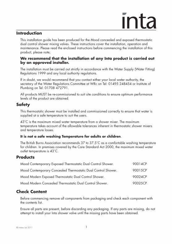
Introduction This installation guide has been produced for the Mood concealed and exposed thermostatic dual control shower mixing valves. These instructions cover the installation, operation and maintenance. Please read the enclosed instructions before commencing the installation of this product, please note;
We recommend that the installation of any Inta product is carried out by an approved installer.
The installation must be carried out strictly in accordance with the Water Supply (Water Fitting) Regulations 1999 and any local authority regulations.
If in doubt, we would recommend that you contact either your local water authority, the secretary of the Water Regulations Committee at WRc on Tel: 01495 248454 or Institute of Plumbing on Tel: 01708 472791.
All products MUST be re-commissioned to suit site conditions to ensure optimum performance levels of the product are obtained.
SafetyThis thermostatic shower must be installed and commissioned correctly to ensure that water is supplied at a safe temperature to suit the users.
43˚C is the maximum mixed water temperature from a shower mixer. The maximum temperature takes account of the allowable tolerances inherent in thermostatic shower mixers and temperature losses.
It is not a safe washing Temperature for adults or children.
The British Burns Association recommends 37 to 37.5˚C as a comfortable washing temperaturefor children. In premises covered by the Care Standard Act 2000, the maximum mixed water outlet temperature is 43˚C.
ProductsMood Contemporary Exposed Thermostatic Dual Control Shower. 90014CP
Mood Contemporary Concealed Thermostatic Dual Control Shower. 90015CP
Mood Modern Exposed Thermostatic Dual Control Shower. 90024CP
Mood Modern Concealed Thermostatic Dual Control Shower. 90025CP
Check Content Before commencing remove all components from packaging and check each component with the contents list.
Ensure all parts are present, before discarding any packaging. If any parts are missing, do not attempt to install your Inta shower valve until the missing parts have been obtained.
© Intatec Ltd 2011 2
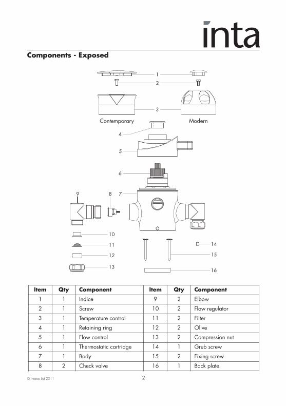
Components - Exposed
Item Qty Component Item Qty Component
1 1 Indice 9 2 Elbow
2 1 Screw 10 2 Flow regulator
3 1 Temperature control 11 2 Filter
4 1 Retaining ring 12 2 Olive
5 1 Flow control 13 2 Compression nut
6 1 Thermostatic cartridge 14 1 Grub screw
7 1 Body 15 2 Fixing screw
8 2 Check valve 16 1 Back plate
6
3
2
1
7
4
5
89
10
11
12
13
14
15
16
Contemporary Modern
© Intatec Ltd 2011 3
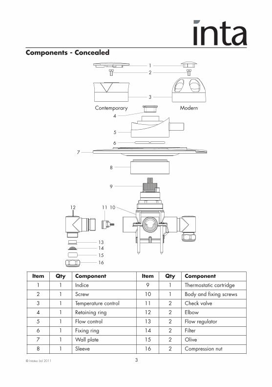
Components - Concealed
Item Qty Component Item Qty Component
1 1 Indice 9 1 Thermostatic cartridge
2 1 Screw 10 1 Body and fixing screws
3 1 Temperature control 11 2 Check valve
4 1 Retaining ring 12 2 Elbow
5 1 Flow control 13 2 Flow regulator
6 1 Fixing ring 14 2 Filter
7 1 Wall plate 15 2 Olive
8 1 Sleeve 16 2 Compression nut
Contemporary Modern
1011
7
8
9
12
13141516
3
21
6
4
5

© Intatec Ltd 2011 4
Technical Data This Inta Mood thermostatic shower valve is suitable for installations on all types of plumbing systems, including gravity supplies, fully pumped, modulating combination boiler, unvented water heater and unbalanced supplies i.e. Cold Mains & Tank Fed Hot. They are not suitable for non-modulating combination boilers.
Max Inlet Pressure (Static) 12 bar Max Inlet Temperature 85˚C Max Inlet Pressure (Dynamic) 5 bar Pre Set Factory Temp Setting 43˚C Min Operating Pressure (Dynamic) 0.2 bar Temperature Stability ±2˚C Max Unbalanced Pressure Ratio 15:1 Min Temp Differential to (with flow regulator) ensure fail-safe between hot Max Unbalanced Pressure Ratio 5:1 and cold supplies 10˚C (without flow regulator) Outlet Connections - Body G½
Unvented Mains Pressure System The drawing shows a typical installation of a shower mixing valve in conjunction with an unvented hot water system. This type of installation must be carried out in accordance with Part G of the Building Regulations.
Whilst pressures are theoretically equal (balanced) most unvented hot systems have a pressure reducing valve on the incoming cold water prior to the hot water storage vessel. This means that the hot and cold pressures can be significantly different.
Most unvented systems use an inlet manifold located directly after the pressure reducing valve.
It is recommended that the cold supply be taken from one of the outlets of the manifold directly to the shower as an independent supply.
For systems without a manifold unit after the pressure reducing valve and where the cold water supply pressure is significantly higher than the hot supply we recommend that a separate pressure reducing valve is fitted to the cold supply, as close as possible to the shower valve and with no draw off points between it and the shower valve.
Flow regulators are required for installations where a PRV is not fitted to ensure simultaneous demand is accounted for.
PRV
Manifold
Cold Supplydirect from Mains
PRV if manifoldnot used

© Intatec Ltd 2011 5
Pumped Systems Pumped systems use a booster pump to increase the pressure of the gravity fed water supplies.
These booster pumps are used where the head of water is insufficient to provide a satisfactory shower or where a high performance shower is required.
Please ensure that the performance of the pump is matched to suit the shower.
Follow the instructions for gravity fed installations taking into account the installation requirements of the pump.
Ensure that the hot and cold water storage capacity is sufficient to supply the shower and any other draw off points that may be used simultaneously.
Most pumps require a minimum head of water to allow the flow switches to operate automatically. Where this is not available a negative head kit may be required to operate the pump.
Please consult the pump manufacturer’s installation requirements
Modulating Combi Boiler / Instantaneous Gas Water Heater The drawing shows a typical installation of a shower valve in conjunction with a combination boiler.
Combi boilers will produce a constant flow of water at a temperature within its operating range. However we recommend that the system should supply hot water in excess of 60˚C.
The hot water flow rates are dependant upon the type of boiler / heater used and the temperature rise required to heat the cold water to the required temperature.
The cold water flow rates may be much greater as they are generally unrestricted from the mains cold water supply. To ensure relatively balanced flow rates, we recommend that a pressure reducing valve or 6 l/min flow regulator is fitted in the cold water supply pipe.
Cold Supplydirect from Mains
Pumps

© Intatec Ltd 2011 6
Gravity System The drawing shows a typical installation of a shower valve on a gravity supplied system.
Please note the minimum head pressure required to ensure correct operation of the valve. In accordance with good plumbing practice, we recommend that a totally independent hot and cold water supply be taken to the valve.
The cold water supply must be connected directly to the water cistern. The hot water supply should be connected to the hot water cylinder via an Essex flange or Sussex flange or to the vent or a draw off pipe as close as possible to the top of the cylinder.
For equal tank fed pressures there is no need to fit the flow regulators. This installation is the recommended minimum for gravity supplies.
For systems with less than 2 metre head pressure, we recommend that a suitable booster pump is fitted to increase the supply pressure.
Cold Mains & Gravity Hot Supplies
If the cold supply to the shower is direct from the cold water mains and the hot water supply is gravity fed from the cold water cistern via the hot water cistern you MUST fit a pressure reducing valve or a 6 l/min flow regulator.
Dimensions - Exposed Valve
35
50
137
136
150
193
4811
3
Contemporary
Modern
Option shownfor mains
pressure cold & low pressure
hot water
Min
. 2m
hea
d

© Intatec Ltd 2011 7
Dimensions - Concealed Valve
Site Preparation - GeneralIt is important to plan the installation thoroughly to suit site conditions before commencing.
• Before commencing the installation ensure site conditions are suitable.
• Depending upon the model, the shower valve is designed for exposed or concealed pipework, whether in a solid or studded wall.
• The thickness of wall tiles, plaster or plaster board should all be considered when positioning the shower valve and routing the hot and cold supply pipes.
• The concealed shower valve must protrude sufficiently from the finished tiled surface to allow the concealing plate and control handle to be fitted.
• Ensure the shower valve will be horizontal when installed.
• The supply pipes can come from below, above, the side or through the wall.
• The concealed shower valve must be installed securely into the wall. If not embedded into the wall with plaster the shower valve must be fixed secure to the studding using screws in the 2 mounting holes.
Ø220
150
136
35
58 to 73
153
Contemporary
Modern
© Intatec Ltd 2011 8
Site Preparation - General • Each shower valve is supplied with integral non return valves in the cold and hot inlet tail pieces to prevent cross contamination of the water supplies. Additional check valves may be necessary in certain circumstances to comply with the Water Regulations. With flexible hose kits, where the hand set is capable of falling within 25 mm of the top of the shower tray, additional backflow prevention devices may be required.
• Where possible, 22 mm hot and cold supplies should be used as close to the valve as possible and pipe runs should be kept to a minimum to maintain flow rates on low pressure installations.
NOTE: The inlets connections to the elbows to the shower valve are 15mm compression.
• Two 6 litre per minute flow regulators are supplied with the shower valve for when inlet pressures exceed 1.0 bar.
• The whole system should be thoroughly flushed, prior to connecting of the hot and cold water supplies to the shower valve, to remove any debris that may be in the supply pipework.
• Ensure there are no joint leaks before finishing the wall.
• Isolation valves must be fitted in an accessible position to both the hot and cold supplies should the valve need to be isolated in the future for servicing.
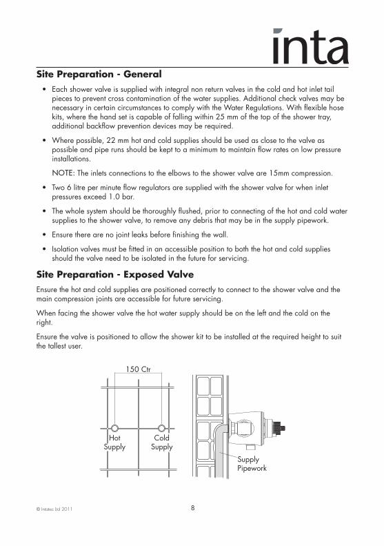
Site Preparation - Exposed ValveEnsure the hot and cold supplies are positioned correctly to connect to the shower valve and themain compression joints are accessible for future servicing.
When facing the shower valve the hot water supply should be on the left and the cold on theright.
Ensure the valve is positioned to allow the shower kit to be installed at the required height to suitthe tallest user.
150 Ctr
HotSupply
ColdSupply
SupplyPipework

© Intatec Ltd 2011 9
Connection - Exposed ValveApply a bead of mastic to the back of the mounting back plate and fit to the wall in the requiredposition using the appropriate wall plugs to suit the wall type.
The Mood shower valve has a bottom ½” male shower connector, suitable for use with a flexiblehose kit.
Fit the valve body to the back plate and secure having first fitted any required flow regulators.
Connect the hot and cold supplies to the valve using the 15mm compression joints and check thejoints for leakage.
Apply a bead of mastic to seal the joints around the hot and cold supply pipes and the jointbetween the wall and the mounting plate/valve.
Fit the temperature and flow controllers to the valve body.
Check the function of the valve, the maximum temperature should not exceed 43˚C. If themaximum mixed water temperature exceeds this the valve must be re-calibrated to suit siteconditions.
Site Preparation - Concealed ValvePrepare the cavity to receive the valve, ensure the hot and cold supplies are positioned correctlyand isolation valves are fitted in an accessible position.
When facing the shower valve the hot water supply should be on the left and the cold on theright.
Fit the back plate to the wall.
In a stud wall it may be necessary to fit a batten to support the valve.
Ensure the valve is positioned to allow the shower kit to be installed at the required height to suitthe tallest user.
150 Ctr
HotSupply
ColdSupply
ShowerConnector
Modern Shown
© Intatec Ltd 2011
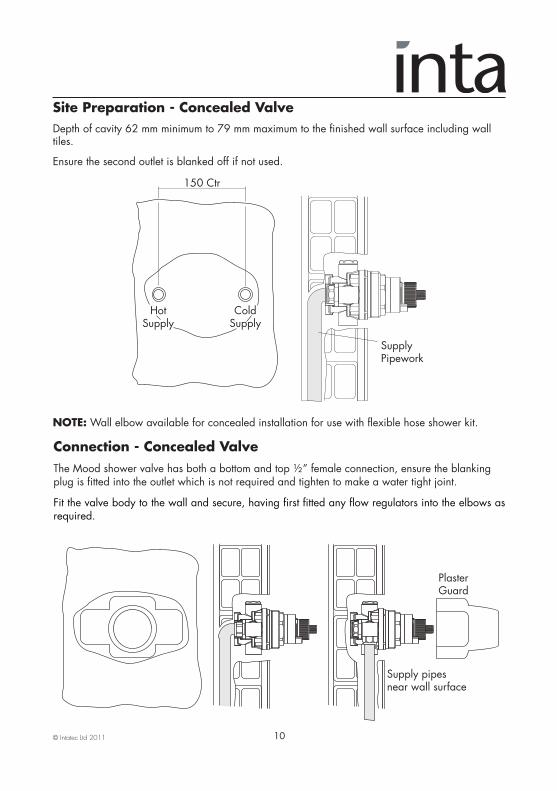
Site Preparation - Concealed ValveDepth of cavity 62 mm minimum to 79 mm maximum to the finished wall surface including walltiles.
Ensure the second outlet is blanked off if not used.
NOTE:Wall elbow available for concealed installation for use with flexible hose shower kit.
10
Connection - Concealed ValveThe Mood shower valve has both a bottom and top ½” female connection, ensure the blankingplug is fitted into the outlet which is not required and tighten to make a water tight joint.
Fit the valve body to the wall and secure, having first fitted any flow regulators into the elbows asrequired.
150 Ctr
HotSupply
ColdSupply
SupplyPipework
PlasterGuard
Supply pipesnear wall surface
© Intatec Ltd 2011 11
Connection - Concealed ValveConnect the hot and cold supplies to the valve using the compression joints provided. The elbowsare designed to allow access to the filters and check valves without the need to disconnect the valvefrom the pipework.
A plaster guard is included to protect the valve whilst the wall surface is finished, including the tiling.
Simply fit the guard over the valve and remove when the wall surface is finished.
Turn on the water supplies and check for leaks.
Check the function of the valve, the maximum temperature should not exceed 43˚C. If themaximum mixed water temperature exceeds this the valve must be re-calibrated to suit siteconditions.
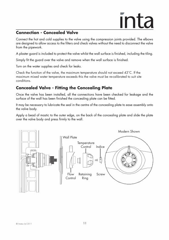
Concealed Valve - Fitting the Concealing PlateOnce the valve has been installed, all the connections have been checked for leakage and thesurface of the wall has been finished the concealing plate can be fitted.
It may be necessary to lubricate the seal in the centre of the concealing plate to ease assembly ontothe valve body.
Apply a bead of mastic to the outer edge, on the back of the concealing plate and slide the plateover the valve body and press firmly to the wall.
Screw
TemperatureControl
Wall Plate
Indice
RetainingRing
FlowControl
Modern Shown
© Intatec Ltd 2011 12
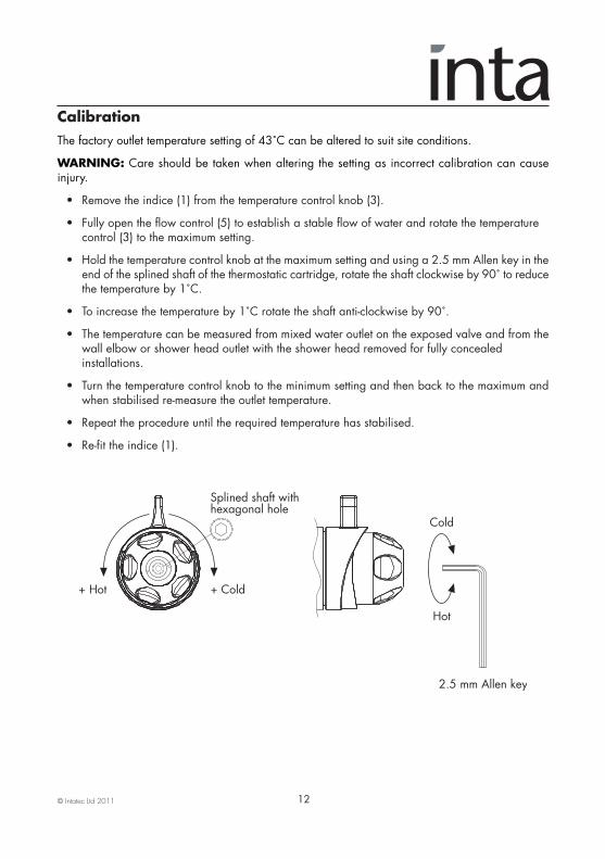
CalibrationThe factory outlet temperature setting of 43˚C can be altered to suit site conditions.
WARNING: Care should be taken when altering the setting as incorrect calibration can causeinjury.
• Remove the indice (1) from the temperature control knob (3).
• Fully open the flow control (5) to establish a stable flow of water and rotate the temperature control (3) to the maximum setting.
• Hold the temperature control knob at the maximum setting and using a 2.5 mm Allen key in theend of the splined shaft of the thermostatic cartridge, rotate the shaft clockwise by 90˚ to reducethe temperature by 1˚C.
• To increase the temperature by 1˚C rotate the shaft anti-clockwise by 90˚.
• The temperature can be measured from mixed water outlet on the exposed valve and from thewall elbow or shower head outlet with the shower head removed for fully concealed installations.
• Turn the temperature control knob to the minimum setting and then back to the maximum andwhen stabilised re-measure the outlet temperature.
• Repeat the procedure until the required temperature has stabilised.
• Re-fit the indice (1).
+ Hot + Cold
Hot
Cold
2.5 mm Allen key
Splined shaft withhexagonal hole
© Intatec Ltd 2011 13
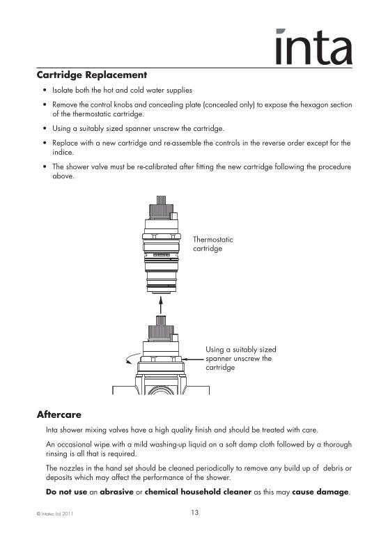
Cartridge Replacement • Isolate both the hot and cold water supplies
• Remove the control knobs and concealing plate (concealed only) to expose the hexagon sectionof the thermostatic cartridge.
• Using a suitably sized spanner unscrew the cartridge.
• Replace with a new cartridge and re-assemble the controls in the reverse order except for the indice.
• The shower valve must be re-calibrated after fitting the new cartridge following the procedure above.
Aftercare Inta shower mixing valves have a high quality finish and should be treated with care.
An occasional wipe with a mild washing-up liquid on a soft damp cloth followed by a thorough rinsing is all that is required.
The nozzles in the hand set should be cleaned periodically to remove any build up of debris or deposits which may affect the performance of the shower.
Do not use an abrasive or chemical household cleaner as this may cause damage.
Using a suitably sizedspanner unscrew the cartridge
Thermostaticcartridge
© Intatec Ltd 2011 14
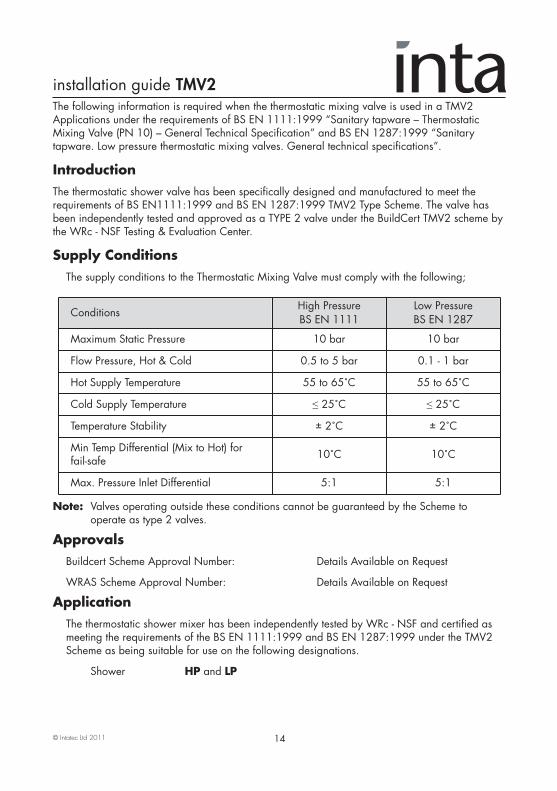
Note: Valves operating outside these conditions cannot be guaranteed by the Scheme to operate as type 2 valves.
Approvals Buildcert Scheme Approval Number: Details Available on Request
WRAS Scheme Approval Number: Details Available on Request
ApplicationThe thermostatic shower mixer has been independently tested by WRc - NSF and certified as meeting the requirements of the BS EN 1111:1999 and BS EN 1287:1999 under the TMV2 Scheme as being suitable for use on the following designations.
Shower HP and LP
The following information is required when the thermostatic mixing valve is used in a TMV2Applications under the requirements of BS EN 1111:1999 “Sanitary tapware – ThermostaticMixing Valve (PN 10) – General Technical Specification” and BS EN 1287:1999 “Sanitarytapware. Low pressure thermostatic mixing valves. General technical specifications”.
IntroductionThe thermostatic shower valve has been specifically designed and manufactured to meet therequirements of BS EN1111:1999 and BS EN 1287:1999 TMV2 Type Scheme. The valve hasbeen independently tested and approved as a TYPE 2 valve under the BuildCert TMV2 scheme bythe WRc - NSF Testing & Evaluation Center.
Supply Conditions The supply conditions to the Thermostatic Mixing Valve must comply with the following;
ConditionsHigh Pressure BS EN 1111
Low PressureBS EN 1287
Maximum Static Pressure 10 bar 10 bar
Flow Pressure, Hot & Cold 0.5 to 5 bar 0.1 - 1 bar
Hot Supply Temperature 55 to 65˚C 55 to 65˚C
Cold Supply Temperature ≤ 25˚C ≤ 25˚C
Temperature Stability ± 2˚C ± 2˚C
Min Temp Differential (Mix to Hot) for fail-safe 10˚C 10˚C
Max. Pressure Inlet Differential 5:1 5:1
installation guide TMV2
© Intatec Ltd 2011 15
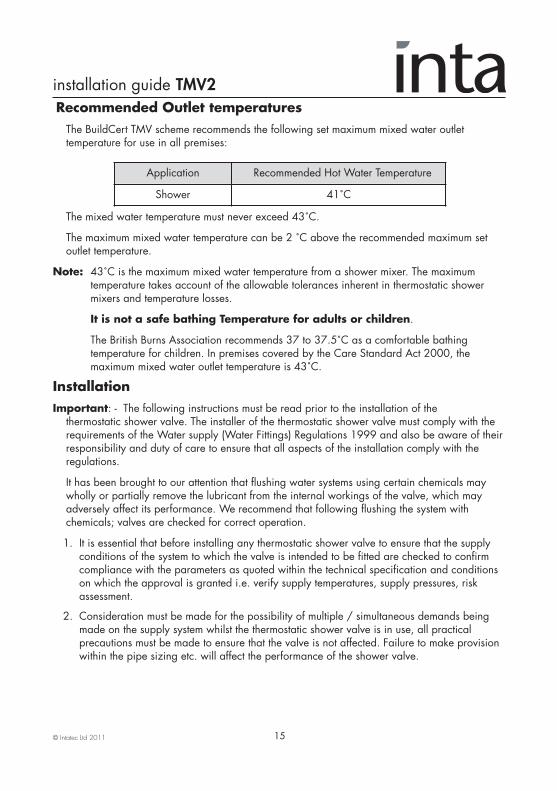
Recommended Outlet temperaturesThe BuildCert TMV scheme recommends the following set maximum mixed water outlet temperature for use in all premises:
The mixed water temperature must never exceed 43˚C.
The maximum mixed water temperature can be 2 ˚C above the recommended maximum set outlet temperature.
Note: 43˚C is the maximum mixed water temperature from a shower mixer. The maximum temperature takes account of the allowable tolerances inherent in thermostatic shower mixers and temperature losses.
It is not a safe bathing Temperature for adults or children.
The British Burns Association recommends 37 to 37.5˚C as a comfortable bathing temperature for children. In premises covered by the Care Standard Act 2000, the maximum mixed water outlet temperature is 43˚C.
InstallationImportant: - The following instructions must be read prior to the installation of the thermostatic shower valve. The installer of the thermostatic shower valve must comply with the requirements of the Water supply (Water Fittings) Regulations 1999 and also be aware of their responsibility and duty of care to ensure that all aspects of the installation comply with the regulations.
It has been brought to our attention that flushing water systems using certain chemicals may wholly or partially remove the lubricant from the internal workings of the valve, which may adversely affect its performance. We recommend that following flushing the system with chemicals; valves are checked for correct operation.
1. It is essential that before installing any thermostatic shower valve to ensure that the supply conditions of the system to which the valve is intended to be fitted are checked to confirm compliance with the parameters as quoted within the technical specification and conditions on which the approval is granted i.e. verify supply temperatures, supply pressures, risk assessment.
2. Consideration must be made for the possibility of multiple / simultaneous demands being made on the supply system whilst the thermostatic shower valve is in use, all practical precautions must be made to ensure that the valve is not affected. Failure to make provision within the pipe sizing etc. will affect the performance of the shower valve.
Application Recommended Hot Water Temperature
Shower 41˚C
installation guide TMV2

© Intatec Ltd 2011 16
Installation 3. The supply to which the thermostatic shower valve is to be installed must be thoroughly flushed and cleaned to remove any debris, which may have accumulated during the installation. Failure to remove any debris will affect the performance and the manufacturer’s warranty of the product. In areas that are subject to aggressive water, provision must be made to treat the supplies prior to the supplies entering the shower valve.
4. The thermostatic shower valve has been designed for horizontal installation and surface mounting.
5. The thermostatic shower valve will be installed in such a position that maintenance of it’s components, associated valves and the commissioning and testing of the shower valve can be undertaken.
6. The hot and cold water supplies must be connected to the valve strictly in accordance with the indications on the body of the valve i.e. hot water supply to the hot port of the valve.
7. In a situation where one or both of the water supplies are excessive, it is recommended to fit a Pressure Reducing Valve to reduce the pressure(s) to within the limits as quoted previously.
8. Any thermostatic shower valve must be fitted with a back flow prevention device, such as check valves to prevent the cross contamination of supplies. The thermostatic shower valve is supplied complete with integral insert check valves and strainers.
9. Isolation valves in an accessible position are required as close as is practicable to the water supply inlets of the thermostatic shower valve.
10. The fitting of strainers is recommended as close as is practicable to the water supply inlets of the thermostatic shower valve.
11. It is essential that the fail safe thermostatic shower valve should not be installed in situations where there is a possibility of the valve being deprived of water or where demands for water are greater than the actual stored supplies.
12. To ensure that the performance levels of the thermostatic shower valve are maintained (in the event of cold water failure), the temperature of the hot water supply at the point of entry to the thermostatic shower valve must be a minimum of 10˚C above the commissioned mixed water discharge temperature.
13. The fail-safe thermostatic shower valve must not be subject to any extreme temperature variations either during the installation or under normal operating conditions.
installation guide TMV2

© Intatec Ltd 2011 17
CommissioningImportant: - The following instructions must be read and understood prior to commissioning the thermostatic shower valve. If under any circumstances there are aspects to the installation / system which do not comply with the specification laid down, the valve MUST NOT be put into operation until the system / installation complies with the specification. However if all these conditions are met, proceed to set the temperature as follows;
1. Ensure that the system is thoroughly cleaned and free from any debris prior to commissioning the thermostatic shower valve.
2. Commissioning the temperatures must be carried out using a suitably calibrated thermometer, preferably a digital thermometer. The sensing part of the thermometer probe must be fully submerged in the water when testing.
3. The valve must be commissioned taking into consideration any fluctuations, which may occur within the system due to simultaneous demands. It is advisable that any outlets which are connected to the same supply as the shower valve are open during setting of the mixed water temperature. It is advisable to ensure that the water temperatures are established before any attempt to commission.
4. Once the supply temperatures are stable and the normal operating conditions are established, the shower valve can be commissioned. The following sequence should be followed when commissioning the valve;
4.1 The first step in commissioning a thermostatic shower valve is to check the following:
• The designation of the thermostatic shower valve matches the application
• The supply pressures are within the valve’s operating range.
• The supply temperatures are within the valve’s operating range.
• Isolating valves (and ‘Y’ strainers preferred) are provided.
4.2 If all these conditions are met, proceed to set the temperature following the procedure described earlier in the Calibration section.
4.3 Measure and record the temperature of the hot and cold water supplies at the connection to the valve.
4.4 Measure and record the temperature of the water discharging from the valve.
4.5 Isolate the cold water supply to the valve and monitor the mixed water temperature.
4.6 Measure and record the maximum mixed water temperature and the final temperature. The final temperature found during the test should not exceed the values quoted.
4.7 Record all the equipment used during the commissioning.
4.8 The mixed water temperature at the terminal fitting must never exceed 2˚C above the set temperature.
installation guide TMV2

© Intatec Ltd 2011 18
Commissioning 5. If the mixed water temperature exceeds the recommended temperature of 41˚C by 2˚C or does not reach 41˚C the shower valve can be adjusted as follows:
5.1 With normal supply conditions established and the hot and cold water supplies running, open the shower valve to its maximum temperature and leave running.
5.2 Remove the indice, retaining screw and handle.
5.3 The temperature stop rings are used to control the temperature, ring A the hot and B the cold water, see diagram on page 12.
5.4 Remove both rings from the cartridge and set the mixed water to the required temperature, maximum 41˚C.
5.5 Temporarily refit the handle and using a digital thermometer it is possible to increase or reduce the mixed water outlet temperature until 41˚C is re-established, by slowly rotating the handle.
5.6 The stop rings are used to set the temperature limits of the shower when in use. When the required temperature is achieved replace the two stop rings on the splined spindle.
6. The above information must be recorded and updated on every occasion when any work is carried out on the valve.
In Service Testing It is a requirement that all TMV2 approved valves shall be verified against the original set temperature results once a year. When commissioning / testing is due the following performance checks shall be carried out.
1. Measure the mixed water temperature at the outlet.
2. Carry out the cold water supply isolation test by isolating the cold water supply, wait for five seconds if water is still flowing check that the temperature is below 43˚C.
3. If there is no significant change to the set outlet temperature (±2˚C or less from the original settings) and the fail-safe shut off is functioning, then the valve is working correctly and no further service work is required.
Notes:
• If there is a residual flow during the commissioning or the annual verification (cold water supply isolation test), then this is acceptable providing the temperature of the water seeping from the valve is no more than 2˚C above the designated maximum mixed water outlet temperature setting of the valve. • Temperature readings should be taken at the normal flow rate after allowing for the system to stabilise. • The sensing part of the thermometer probe must be fully submerged in the water to be tested. • Any thermostatic shower that has been adjusted or serviced must be re-commissioned and re-tested in accordance with the manufacturers’ instructions
installation guide TMV2

© Intatec Ltd 2011
Intatec LtdAirfield Industrial Estate
HixonStaffordshire
ST18 0PF
Tel: 01889 272 180Fax: 01889 272 181
email: [email protected]: www.intatec.co.ukE & O.E
15-04-11
Notes
Please leave this Manual for the User