
MONTREAL PROTOCOL ON SUBSTANCES THAT DEPLETE … · MONTREAL PROTOCOL ON SUBSTANCES THAT DEPLETE...
178
MONTREAL PROTOCOL ON SUBSTANCES THAT DEPLETE THE OZONE LAYER UNEP Technology and Economic Assessment Panel TEAP 2010 PROGRESS REPORT VOLUME 1 “ASSESSMENT OF HCFCS AND ENVIRONMENTALLY SOUND ALTERNATIVES” “SCOPING STUDY ON ALTERNATIVES TO HCFC REFRIGERANTS UNDER HIGH AMBIENT TEMPERATURE CONDITIONS” May 2010
Transcript of MONTREAL PROTOCOL ON SUBSTANCES THAT DEPLETE … · MONTREAL PROTOCOL ON SUBSTANCES THAT DEPLETE...

MONTREAL PROTOCOL
ON SUBSTANCES THAT DEPLETE
THE OZONE LAYER
UNEP
Technology and Economic Assessment Panel
TEAP 2010 PROGRESS REPORT
VOLUME 1
“ASSESSMENT OF HCFCS AND
ENVIRONMENTALLY SOUND ALTERNATIVES”
“SCOPING STUDY ON ALTERNATIVES TO HCFC REFRIGERANTS UNDER HIGH AMBIENT TEMPERATURE CONDITIONS”
May 2010


TEAP 2010 PROGRESS REPORT
VOLUME 1
“ASSESSMENT OF HCFCS AND
ENVIRONMENTALLY SOUND ALTERNATIVES”
“SCOPING STUDY ON ALTERNATIVES TO HCFC REFRIGERANTS
UNDER HIGH AMBIENT TEMPERATURE CONDITIONS”
May 2010

May 2010 TEAP Progress Report Volume 1 iv
Montreal Protocol On Substances that Deplete the Ozone Layer
Report of the UNEP Technology and Economic Assessment Panel
May 2010
VOLUME 1 “ASSESSMENT OF HCFCS AND ENVIRONMENTALLY SOUND ALTERNATIVES” “SCOPING STUDY ON ALTERNATIVES TO HCFC REFRIGERANTS UNDER HIGH AMBIENT TEMPERATURE CONDITIONS”
The text of this report is composed in Times New Roman.
Co-ordination: TEAP, its XIX/8 and XXI/9 Task Force
Composition: Lambert Kuijpers (UNEP TEAP) Layout: Ozone Secretariat (UNEP) Lambert Kuijpers (UNEP TEAP)
Reproduction: UNON Nairobi
Date: May 2010
Under certain conditions, printed copies of this report are available from: UNITED NATIONS ENVIRONMENT PROGRAMME Ozone Secretariat, P.O. Box 30552, Nairobi, Kenya This document is available in portable document format from
http://www.ozone.unep.org/
No copyright involved. This publication may be freely copied, abstracted and cited, with acknowledgement of the source of the material.
Printed in Nairobi, Kenya, 2010.
ISBN: 9966-7319-3-8

TEAP 2010 PROGRESS REPORT
VOLUME 1
“ASSESSMENT OF HCFCS AND ENVIRONMENTALLY SOUND ALTERNATIVES”
“SCOPING STUDY ON ALTERNATIVES
TO HCFC REFRIGERANTS UNDER HIGH AMBIENT TEMPERATURE CONDITIONS”
May 2010

May 2010 TEAP Progress Report Volume 1 vi
DISCLAIMER The United Nations Environment Programme (UNEP), the Technology and Economic Assessment Panel (TEAP) co-chairs and members, the Technical Options Committees chairs, co-chairs and members, the TEAP Task Forces co-chairs and members, and the companies and organisations that employ them do not endorse the performance, worker safety, or environmental acceptability of any of the technical and economic options discussed. UNEP, the TEAP co-chairs and members, the Technical Options Committees chairs, co-chairs and members, and the Technology and Economic Assessment Panel Task Forces co-chairs and members, in furnishing or distributing the information that follows, do not make any warranty or representation, either express or implied, with respect to the accuracy, completeness, or utility; nor do they assume any liability of any kind whatsoever resulting from the use or reliance upon any information, material, or procedure contained herein. ACKNOWLEDGEMENTS The UNEP Technology and Economic Assessment Panel and the XXI/9 Task Force co-chairs and members wish to express thanks to all who contributed from governments, both Article 5 and non-Article 5, to the Ozone Secretariat, as well as to a large number of individuals involved in Protocol issues, without whose involvement this report would not have been possible. The opinions expressed are those of the Panel and its Task Force and do not necessarily reflect the reviews of any sponsoring or supporting organisation.

May 2010 TEAP Progress Report Volume 1 vii
Foreword
The TEAP 2010 Progress Report
The May 2010 TEAP Progress Report consists of two volumes: Volume 1 The Decision XXI/9 Task Force Report, and the “final” Decision XIX/8 Task Force Report Volume 2 TOC Progress Reports and Other Task Force Reports Volume 1 Volume 1 contains: (1) the report of the Decision XXI/9 Task Force on the assessment of HCFCs and environmentally sound alternatives and (2) the final report of the Decision XIX/8 Task Force dealing with the “scoping study on HCFC alternatives under high ambient temperature conditions”.
Volume 2 Volume 2 contains the essential use report, TOC progress reports, the QPS Task Force report (as requested in decision XXI/10), the MBTOC progress and preliminary CUN evaluation report, as well as TEAP organisation issues and TEAP-TOC membership lists This report is the Volume 1 report.
The UNEP Technology and Economic Assessment Panel: Stephen O. Andersen, co-chair USA Marta Pizano COL Lambert Kuijpers, co-chair NL Ian Porter AUS José Pons-Pons, co-chair VEN Miguel Quintero COL Paul Ashford UK Ian Rae AUS Mohamed Besri MOR Helen Tope AUS David Catchpole UK Dan Verdonik USA Biao Jiang PRC Ashley Woodcock UK Michelle Marcotte CDN Masaaki Yamabe J Thomas Morehouse USA Shiqiu Zhang PRC Roberto Peixoto BRA


TEAP 2010 PROGRESS REPORT
DECISION XXI/9
“ASSESSMENT OF HCFCS AND
ENVIRONMENTALLY SOUND ALTERNATIVES”
May 2010


May 2010 TEAP XXI/9 Task Force Report xi
Table of Contents EXECUTIVE SUMMARY..................................................................................................... 1
POTENTIAL LOW-GWP OPTIONS ............................................................................................. 8
1 INTRODUCTION ....................................................................................................... 15
1.1 DECISION XXI/9 .................................................................................................... 15 1.2 THE PROCESS......................................................................................................... 16
2 DEFINING “LOW-GWP” AND “HIGH-GWP” SUBSTANCES .......................... 19
2.1 INTRODUCTION ...................................................................................................... 19 2.2 RADIATIVE FORCING AND GWP ............................................................................ 20 2.3 ISSUES INVOLVED IN THE GWP METRICS............................................................... 21 2.4 IMPLICATIONS IN DEFINING “LOW-GWP” AND RELEVANCE FOR DECISION XXI/9 22 2.5 TOXICITY AND FLAMMABILITY ASPECTS IN CONSIDERING “LOW-GWP”
SUBSTANCES .......................................................................................................... 25
3 METHODS AND METRICS FOR PRIORITISING INVESTMENT TO MINIMISE CLIMATE IMPACTS FROM TECHNOLOGY SELECTED TO PHASE OUT ODSS..................................................................................................... 27
3.1 INTRODUCTION ...................................................................................................... 27 3.2 METHODOLOGY FOR ESTIMATING REFRIGERANT, FOAM BLOWING, AND HALON
BANKS AND EMISSIONS ......................................................................................... 29 3.3 SINGLE AND MULTIPLE FACTOR ENVIRONMENTAL PERFORMANCE METRICS ....... 30
3.3.1 Ozone-Specific – Single Factor ....................................................................... 30 3.3.2 Climate-Specific – Single Factor..................................................................... 31
3.3.2.1 Global-Warming-Potential (GWP) ......................................................................... 31 3.3.2.2 Product Energy Efficiency ...................................................................................... 31 3.3.2.3 Electricity Carbon Footprint ................................................................................... 31 3.3.2.4 Chemical Nomenclature.......................................................................................... 31
3.3.3 Climate-Specific – Multi-Factor...................................................................... 32 3.3.3.1 Carbon Footprint Offset (CFO)............................................................................... 32 3.3.3.2 Total Equivalent Warming Impact (TEWI) ............................................................ 32 3.3.3.3 Life-Cycle Climate Performance (LCCP)............................................................... 33 3.3.3.4 Functional Unit Approach (FUA) ........................................................................... 33 3.3.3.5 Multilateral Fund Climate Impact Indicator (MCII) .............................................. 33
3.3.4 Environmental – Multi-Factor......................................................................... 34 3.4 CONCLUSIONS........................................................................................................ 35
4 DOMESTIC REFRIGERATION .............................................................................. 37
4.1 BACKGROUND........................................................................................................ 37 4.2 REFRIGERANT OPTIONS ......................................................................................... 37 4.2.1 NEW EQUIPMENT OPTIONS .................................................................................... 37
4.2.2 Not-In-Kind Alternative Technologies............................................................. 38 4.2.3 Service of Existing Equipment......................................................................... 38 4.2.4 Product Energy Efficiency Improvement Technologies................................... 38 4.2.5 Refrigerant Annual Demand............................................................................ 38
5 LOW-GWP ALTERNATIVES FOR COMMERCIAL REFRIGERATION........ 41
5.1 BACKGROUND........................................................................................................ 41 5.2 LOW-GWP ALTERNATIVES FOR STAND-ALONE EQUIPMENT................................. 43 5.3 LOW-GWP ALTERNATIVES FOR CONDENSING UNIT SYSTEMS .............................. 45 5.4 LOW-GWP ALTERNATIVES FOR SUPERMARKET SYSTEMS .................................... 47 5.5 CONCLUSIONS........................................................................................................ 50
6 INDUSTRIAL REFRIGERATION ........................................................................... 51
May 2010 TEAP XXI/9 Task Force Report xii
6.1 USE OF HFCS......................................................................................................... 51 6.2 USE OF HCFCS ...................................................................................................... 51 6.3 CURRENT OR FUTURE USE OF LOW-GWP SUBSTANCES ........................................ 51
6.3.1 Ammonia.......................................................................................................... 51 6.3.3 Carbon dioxide ................................................................................................ 51 6.3.4 Hydrocarbons.................................................................................................. 51
6.4 MARKETS............................................................................................................... 52
7 TRANSPORT REFRIGERATION ........................................................................... 55
7.1 INTRODUCTION ...................................................................................................... 55 7.2 USE OF HCFCS ...................................................................................................... 55 7.3 CURRENT AND FUTURE USE OF LOW-GWP SUBSTANCES ...................................... 56 7.4 MARKETS............................................................................................................... 58
8 UNITARY AIR CONDITIONING ............................................................................ 61
8.1 DESCRIPTION OF PRODUCT CATEGORY.................................................................. 61 8.2 CURRENT SITUATION ............................................................................................. 61
8.2.1 Primary HCFC-22 Replacements.................................................................... 61 8.2.2 Developed Country Status ............................................................................... 62 8.2.3 Developing Country Status.............................................................................. 62
8.3 POTENTIAL LOW-GWP OPTIONS ........................................................................... 62 8.3.1 HFC-32............................................................................................................ 62 8.3.2 HFC-1234yf and Blends with Other HFCs...................................................... 63 8.3.3 Hydrocarbon Refrigerants............................................................................... 63 8.3.4 R-744 (Carbon Dioxide).................................................................................. 63 8.3.5 Product Energy Efficiency Improvement Technologies................................... 64
9 CHILLER AIR CONDITIONING ............................................................................ 67
9.1 INTRODUCTION ...................................................................................................... 67 9.2 USE OF HCFCS ...................................................................................................... 67 9.3 CURRENT OR FUTURE USE OF LOW-GWP SUBSTANCES ........................................ 68
9.3.1 R-717 (ammonia)............................................................................................. 68 9.3.2 Hydrocarbons.................................................................................................. 69 9.3.3 R-744 (carbon dioxide).................................................................................... 69 9.3.4 R-718 (water vapour) ...................................................................................... 70 9.3.5 HFC-1234yf..................................................................................................... 70
9.4 MARKETS............................................................................................................... 70 9.6 APPENDIX: SOME STANDARDS FOR ENSURING SAFE APPLICATION OF
REFRIGERANTS ...................................................................................................... 71
10 VEHICLE AIR CONDITIONING ............................................................................ 73
10.1 INTRODUCTION ...................................................................................................... 73 10.2 OPTIONS FOR FUTURE MOBILE AIR CONDITIONING SYSTEMS ............................... 73
10.2.1 Bus and Rail Air Conditioning ........................................................................ 73 10.2.2 Passenger Car and Light Truck Air Conditioning........................................... 73
10.2.2.1 Improved HFC-134a Systems ................................................................................. 74 10.2.2.2 Carbon Dioxide (R-744) Systems ........................................................................... 74 10.2.2.3 HFC-152a Systems ................................................................................................. 74 10.2.2.4 Blend Alternatives .................................................................................................. 75 10.2.2.5 HFC-1234yf Systems.............................................................................................. 76
11 FOAMS......................................................................................................................... 85
11.1 ALTERNATIVE FOAM TECHNOLOGIES .................................................................... 85 11.2 FOAMS AND OTHER PRODUCTS FOR INSULATION APPLICATIONS ........................... 85 11.3 POLYURETHANE (PU) FOAMS................................................................................ 86 11.4 ESTABLISHED HCFC ALTERNATIVES .................................................................... 87

May 2010 TEAP XXI/9 Task Force Report xiii
11.5 EMERGING HCFC ALTERNATIVES......................................................................... 88 11.6 POLYSTYRENE (XPS) BOARD FOAMS .................................................................... 89
12 FIRE PROTECTION.................................................................................................. 91
12.1 INTRODUCTION ...................................................................................................... 91 12.2 REPLACEMENTS AND ALTERNATIVES .................................................................... 91
13 SOLVENTS.................................................................................................................. 95
13. 1 DESCRIPTION OF PRODUCT CATEGORY.................................................................. 95 13.2 HCFC SOLVENTS................................................................................................... 96 13.3 HFC SOLVENTS ..................................................................................................... 96 13.4 POTENTIAL HCFC AND HFC REPLACEMENTS ....................................................... 97 13.5 CONSUMPTION / EMISSIONS ................................................................................... 99
14 INHALED THERAPY FOR ASTHMA AND COPD ............................................ 101
15 CONCLUSIONS........................................................................................................ 105
16 ACRONYMS.............................................................................................................. 111
ANNEX 1 REPRODUCTION OF THE IPCC WGI GWP TABLE (2.14) ................... 113


May 2010 TEAP XXI/9 Task Force Report 1
Executive Summary Decision XXI/9, paragraph 2, requests the Technology and Economic Assessment Panel to include the following in its 2010 Progress Report: (a) To list all sub-sectors using HCFCs, with concrete examples of
technologies where low-GWP alternatives are used, indicating what substances are used, conditions of application, their costs, relative energy efficiency of the applications and, to the extent possible, available markets and percentage share in those markets, and to collect concrete information from various sources including information voluntarily provided by Parties and industries. To further ask TEAP to compare these alternatives with other existing technologies, in particular, high-GWP technologies that are in use in the same sectors;
(b) To identify and characterize the implemented measures for ensuring safe
application of low-GWP alternative technologies and products as well as barriers to their phase-in, in the different sub-sectors, collecting concrete information from various sources including information voluntarily provided by Parties and industries;
(c) To provide a categorization and reorganization of the information
previously provided in accordance with decision XX/8 as appropriate, updated to the extent practical, to inform the Parties of the uses for which low- or no-GWP and/or other suitable technologies are or will soon be commercialized, including to the extent possible the predicted amount of high-GWP alternatives to ozone-depleting substances uses that can potentially be replaced.
In fact, the decision requests to update the XX/8 report as submitted to the Parties in 2009, via a categorisation and reorganisation of the information provided, with emphasis on where “low-GWP” technologies are or will be used, and the potential replacement of high GWP alternatives. The three requests in paragraphs (a), (b) and (c) have been considered in one report describing all relevant subsectors where it concerns “low-GWP” and “high-GWP” as alternative technologies for HCFCs and the current and future use of “low-GWP” technologies, including the replacement of “high-GWP” technologies. TEAP established a Task Force to update the data contained in the Panel’s 2009 XX/8 report and to report on the issues mentioned in the three paragraphs above. This XXI/9 Task Force has been co-chaired by four TEAP members. The report contains 15 chapters, with 11 chapters describing technology sectors or subsectors. Twelve Chapter Lead Authors were involved, including several Task Force co-chairs, as well as 27 Reviewing Authors.
May 2010 TEAP XXI/9 Task Force Report 2
Semi-final drafts of the single chapters were put together as the XXI/9 report. Draft reports were circulated for comments to the entire Chapter Lead Author and Reviewing Author group until the beginning of April 2010. The report was subsequently submitted to the entire TEAP membership and was reviewed by the TEAP at its meeting 19-23 April 2010 in Madrid, Spain. Comments from TEAP members were considered for insertion and the report was circulated to the Task Force members for a last round of comments and suggestions. The final XXI/9 report was then submitted to UNEP by the beginning of May 2010. Low-GWP and high-GWP (chapter 2) The report contains considerations on the definition of “low-GWP” and “high-GWP” in chapter 2, since a clear definition has so far not been given by the Parties or by TEAP in its reports requested by the Montreal Protocol Parties. In the consideration of the emission of global warming chemicals, including the (indirect) emission of carbon dioxide in the generation of electricity for the operation of certain equipment, it is necessary to apply certain methodologies. An overview of these is given in chapter 3. Chapters 4 through 14 describe specific sectors and subsectors with emphasis on the requests made in Decision XXI/9. The Kyoto Protocol uses values for the GWP specified in the Second Assessment Report of the Intergovernmental Panel on Climate Change (IPCC, 1996) despite the fact that later IPCC assessments have revised (and expanded) the tables, which list detailed, updated values for GWPs. The latest comprehensive table with GWP values for a large variety of natural and synthetic substances can be found in the IPCC Fourth Assessment Report, Working Group I. This table is reproduced in this report. The global warming potential is based on the radiative forcing integrated over a specific time period due to a pulse emission of a unit mass of gas. It can be quoted as an absolute global warming potential (AGWP), e.g., in units of Wm-2 kg-1 year-1 (in other words, as a multiple of the increase in heat per square meter that the release of 1 kg would cause over one year). Or, it can be quoted as a dimensionless value by dividing the AGWP by the AGWP of a reference gas, typically CO2, yielding the normally used Global Warming Potential (GWP). A second choice is the time horizon over which the integration is performed; this is a choice to be made (by the user). The Kyoto Protocol has adopted GWP values for a time horizon of 100 years. The choice of the time horizon in the Protocol is not based on any published, conclusive discussion and IPCC science assessments have generally presented GWPs for three time horizons, i.e., 20, 100 and 500 years. The terms “high-GWP” or “low-GWP” are comparative in nature. In the context of the Montreal Protocol and the sectors the Montreal Protocol relates to, partly halogenated substances are currently the most broadly used after the

May 2010 TEAP XXI/9 Task Force Report 3
phase-out of CFCs, halons and CTC. The most commonly used of these substances, representing --as of the writing of this report-- more than 95% of the global use of these substances in metric tonnes, have GWPs (100 year time horizon) between 700 and 4000, with a median value of slightly more than 2000. The terms “high-GWP” and “low-GWP” in the context of different alternative substances for these sectors should therefore relate in some way to this bandwidth (/average). The report considers advantages and disadvantages related to four possible classes of substances for a low or lower GWP. These four classes tend to be a factor of around 10 or more below the currently most prevalent alternatives. An order of magnitude (which is a factor of 10) has often been a common denominator to separate “high” and “low”, see also logarithmic scales etc. However, the Task Force agreed on using √10 (=3.16), or roughly a factor 3 as a more smooth and smaller denominator. The Task Force proposal is to classify GWPs of greenhouse gases as follows: GWP < ~30 “very low-GWP” (“ultra-low”1) GWP < ~100 “very low-GWP” GWP < ~300 “low-GWP” GWP < ~1000 “moderate-GWP” GWP < ~3,000 “high-GWP” GWP < ~10,000 “very high GWP” GWP > ~10,000 “ultra-high GWP” It should be pointed out here that this classification is by nature relative, since it refers to current use patterns; one also knows that technology continuously changes, which will have consequences for the perception of different GWP values. The classification will require adjustment and revision in future, based upon the agreed principles. Toxicity and flammability are characteristics of substances which are assessed against benchmarks that evolve over time as new technology can mitigate flammability and toxicity risk and the risk of climate change has to be balanced against product risk at a certain time. If toxic substances cannot be applied under certain circumstances or in certain types of products, it may lead to the application of substances with GWPs higher than a certain minimum value. For example, if moderate to low flammability is essential in typical commercial installations, HFCs or HFC mixtures with GWPs higher than 500-600 may then be required. This would then currently be the lowest technically feasible GWP option, however, this may be revised downwards with future technical development.
1 Although one could use the term “ultra-low”, it is proposed to also use the term “very low” for substances with GWPs lower than 30. This is done because this range also includes carbon dioxide (although having a GWP of 1) being the largest contributor to human induced global warming

May 2010 TEAP XXI/9 Task Force Report 4
Methods and metrics (Chapter 3) The ultimate choice of technology to phase-out HCFCs will be based on ozone depletion and also climate impact, health, safety, affordability and availability, as Decision XIX/6 requires. Methods and metrics can identify and quantify the benefits of technology superior in protecting ozone and climate. The results depend on the accuracy and completeness of the input data, the appropriateness of assumptions and the sophistication of the model. Choosing the lowest GWP substance in the technology replacing HCFCs may not always be the optimum approach because the GHG emissions from product manufacturing and product energy use often dominate the life-cycle carbon footprint. When available, LCCP calculations are the most comprehensive method to determine the direct and indirect greenhouse gas emissions at the product level. LCCP models need more development to be transparent, adaptable to local climate and electricity carbon intensity situations. When LCCP models are not available, appropriate, or the necessary data to apply them is not yet available, other methods and metrics will be useful. Chapter 3 presents single and multiple factor environmental performance metrics including: Ozone-Depletion Potential (ODP), Global-Warming-Potential (GWP), Product Energy Efficiency, Electricity Carbon Footprint, Chemical Nomenclature, Carbon Footprint Offset (CFO), Total Equivalent Warming Impact (TEWI), Life-Cycle Climate Performance (LCCP), Functional Unit Approach (FUA), Multilateral Fund Climate Impact Indicator (MCII), and Life-Cycle Assessment (LCA). The Multilateral Fund Climate Impact Indicator (MCII) evolved from the Functional Unit Approach and is essentially a simplified version of the LCCP. Chapter 4 In domestic refrigeration, about 63 percent of newly produced refrigerators employ HFC-134a refrigerant. About 36 percent employ hydrocarbon refrigerants mainly Isobutane (HC-600a). Blends of HC-600a and HC-290 are used in some cases to avoid the need to re-engineer compressors. Both HFC-134a and HC-600a deliver comparable energy efficiency with design variation providing more difference than the different refrigerants. Within 10 years, it is predicted that at least 75 percent of global new refrigerator production will use hydrocarbon refrigerants. The required changes in standards to achieve this are underway. Alternative refrigeration technologies continue to be pursued for specific narrow applications such as portability or lack of access to an electricity supply. In the absence of unique drivers such as these, no identified technology can compete for cost or efficiency with conventional vapour-compression technology for mass-produced equipment. Energy labelling and

May 2010 TEAP XXI/9 Task Force Report 5
energy regulations are widely used to promote improved product energy efficiency. Options to significantly improve product energy efficiency have demonstrated mass production feasibility. Chapter 5 Commercial refrigeration is characterised by a wide variety of equipment. Technical solutions for replacement of HCFC-22 by low GWP refrigerants vary depending on the three families of refrigeration systems: 1) stand-alone equipment, 2) condensing units and 3) centralised systems. Stand-alone equipment, systems where all refrigeration components are integrated, including freezers, vending machines, and beverage coolers are extensively used in many non-Article 5 and Article 5 countries. The current dominant refrigerant is HFC-134a (GWP = 1440). Low-GWP alternatives have been used for several years in commercial freezers and vending machines. Hydrocarbons (propane and isobutane) exhibit identical energy performances compared to HFC-134a; their uses are limited owing to their flammability and their installation in commercial outlets. The charge limit of 150 g is often used as the reference. CO2 is also applied in some of these systems and presents lower energy performances compared to HFCs particularly in hot climates. The refrigerants “banked” in stand-alone equipment represent ~7 % of the total commercial refrigeration bank. Condensing units exhibit refrigerating capacities ranging typically from 1 kW to 20 kW. They are composed of one (or two) compressor(s), one condenser, and one receiver assembled into a so-called “condensing unit”, which is located external to sales area. In most of the A5 countries, the use of condensing units is very extensive. The dominant refrigerants apart from HCFC-22 are currently HFC-134a and R-404A. The refrigerants “banked” in these units represent ~47 % of the total commercial refrigeration bank. Condensing units constitute the most difficult group of equipment for an uptake of low-GWP alternatives because the market is driven by cost and the design is simple with HCFC-22. Low-GWP alternatives such as hydrocarbons, CO2 and also ammonia have been tested and installed in a number of small supermarkets as well as other commercial outlets. In Northern Europe, a market characterised by a low condensing temperature, CO2 is increasing in market share. Centralized systems consist of racks of compressors connected by long lines with the display-cases in the sales area. This concept --defined as direct expansion-- requires large quantities of refrigerant varying from some hundreds of kilograms to more than 1.5 tonnes. The refrigerants “banked” in centralized systems represent ~46 % of the total commercial refrigeration bank. Except for most of Europe and Japan, the dominant refrigerant is still HCFC-22.

May 2010 TEAP XXI/9 Task Force Report 6
In order to limit the refrigerant charge, and the resulting refrigerant emissions, indirect systems using a secondary heat transfer fluid such as MPG (Mono-Propylene-Glycol) can be used to transfer the heat from the display cases to the machinery room. Indirect systems can limit the refrigerant charge by a factor 2 to 4. Refrigerating capacities are generated by independent racks of compressors at two main levels of evaporating temperatures -40 / -35°C for frozen food (and ice-creams) and -15 / -10°C for fresh food (dairy, meat, etc.). Even if the choice has not been the current one until now, refrigerants adapted to each of the two levels of temperature seems the more appropriate solution for the future, especially when favoring low-GWP options. This is because CO2 is well adapted to the low evaporating temperature provided that its condensation is done between -5 and +10 °C. The competition between the alternatives for HCFC-22 replacement is focused on the medium temperature level of -15 to -10 °C). Ammonia, hydrocarbons (and also CO2 in cold climates) as well as unsaturated HFCs as HFC-1234yf blended with HFCs such as HFC-32 are being considered. Chapter 6 Transport refrigeration serves primarily the cold food chain. The main HCFC working fluid is HCFC-22 and its blends. However, the absolute majority of new transport refrigeration equipment utilizes HFC working fluids. Development of low-GWP systems is under way but it meets technical challenges because of the sector specific requirements such as equipment robustness, low weight, corrosion resistance and safety. The most promising candidates include hydrocarbons and carbon dioxide. Cryogenic (open-loop) systems and eutectic plates are being utilized in some vehicles, but they cannot be considered for all applications, such as marine containers. A relatively short equipment lifetime of about 10-15 years makes it possible (except for marine vessels; 20-25 years) that any equipment marketed today may not be in operation by 2025. Chapter 7 Ammonia has been used as the refrigerant in Industrial Refrigeration Systems for many years. However, there are significant regional variations. Where ammonia is not acceptable for toxicity reasons, carbon dioxide has been used, either in cascade with a smaller ammonia plant or with a fluorocarbon. It has been used also in high pressure (“transcritical”) systems. In some cases, for example freezers or information technology (IT) equipment cooling, carbon dioxide offers additional advantages in efficiency. There is also a significant bank of HCFC refrigerant in industrial systems, particularly HCFC-22. Individual system charge can be high – in some cases several tonnes of refrigerant. These systems tend to have a longer life than commercial equipment, often lasting over 20 years, but leakage rates can be

May 2010 TEAP XXI/9 Task Force Report 7
high, particularly in older plants. A “drop-in” blend for replacing HCFC-22 in flooded industrial systems has not been developed; the common replacement blends used in commercial refrigeration such as R-407A or R-422D have a significant “temperature glide” and are therefore difficult or impossible to use in large industrial systems. The cost of these blends is also a significant barrier to their use. HFCs have not been widely used in large industrial systems. Where they have been adopted it is generally in low charge systems, which reduce the environmental and financial consequences of refrigerant loss. It is very unlikely that unsaturated HFC refrigerants, whether single compounds or blends, will be adopted for use in industrial systems. This is because the risk of refrigerant decomposition due to the presence of contaminants is too great. Users of HCFCs in smaller industrial systems are now faced with the difficult choice of whether to switch to high GWP HFCs and run the risk of a further round of phaseouts in a few years’ time, or to change to ammonia and/or carbon dioxide and deal with the change in operating practices that those refrigerants would require. There is significant need, particularly in Article 5 countries, for assistance for operators seeking to implement ammonia and/or carbon dioxide in their industrial refrigeration systems. Such assistance includes operator training, grants to support increased capital cost associated with these installations and the development of lower charge, fully automatic systems which are more like the older HCFC systems than a traditional pumped ammonia plant. Chapter 8 On a global basis, air-cooled air conditioners and heat pumps ranging in size from 2.0 kW to 420 kW comprise a vast majority of the air conditioning market below approximately 1,300 kW. Nearly all air-cooled air conditioners and heat pumps manufactured prior to 2000 used HCFC-22 as their working fluid. This corresponds to an HCFC bank of 1.2 million tonnes. In developed countries, HFC refrigerants have been the dominant replacements for HCFC-22 in all categories of unitary air conditioners. The most widely used replacement is R-410A. Hydrocarbons have been used in some low charge applications. The transition away from HCFC-22 is well underway or nearly complete in most developed countries. Most developing countries are continuing to utilise HCFC-22 as the predominate refrigerant in unitary air conditioning applications. The most likely short-term replacements for use in developing countries are the HFC blends R-410A and R-407C for most applications and hydrocarbon refrigerants in smaller capacity packaged applications.

May 2010 TEAP XXI/9 Task Force Report 8
Potential Low-GWP Options in AC HFC-32 is becoming a lower GWP alternative to R-410A, which is a 50-50 blend of HFC-32 and HFC-125 to reduce flammability. With additional capabilities and experience in using flammable refrigerants, HFC-32, which can be more efficient than R-410A in many cases, is likely to be used as an alternative to HCFC-22 and the higher GWP R-410A in many applications. HFC-32 systems are expected to be lower costs than the current R-410A systems. Hydrocarbon refrigerants are expected to see increased usage in low charge packaged applications (less than 1 kg of refrigerant). A high proportion of air conditioning products are of the “split” type. In contrast to packaged or stand-alone equipment, such as portable or window air conditioners, the installing contractor plays an important role in the safety of the final installation of split systems. The dependence on an independent third party to insure the safe installation of split system air conditioners will likely restrict the use of hydrocarbon refrigerants primarily to low charge packaged applications. Low-GWP, unsaturated HFCs and blends containing unsaturated HFCs are expected to emerge as additional replacement options for R-410A and R-407C. Flammability and performance issues remain to be addressed. HFC-1234yf is one such low-GWP unsaturated HFC. This refrigerant has been developed to replace HFC-134a in automotive applications. However, for other applications, blends of HFC-1234yf with other HFC refrigerants can be applied low-GWP alternatives to R-410A and R-407C. Systems using these blends are expected to be at a much higher cost than existing R-410A and R-407C systems. R-744, which is the refrigerant designation for CO2, will see some usage in low ambient applications. The high cost of addressing the system efficiency issues will need to be addressed before broad application of R-744 in air-to-air air conditioning and heat pump applications can occur. R-744 air conditioners are more likely to be applied in cool to moderately warm climates where the costs of addressing the efficiency will be more cost effective. Chapter 9 Centrifugal chillers in developed countries and in Article 5 countries alike employ the same refrigerants, i.e., HFC-134a or HCFC-123. There are no low-GWP replacements that have been commercialised yet to replace either refrigerant for centrifugal chillers. R-717 (ammonia) chillers are manufactured in small quantities compared to HFC chillers of similar capacity. Applications in comfort cooling have been less common than in process cooling and the primary market for R-717 chillers has been Europe. Chillers employing ammonia as a refrigerant have been produced for many years. If the use of this refrigerant is to expand in the

May 2010 TEAP XXI/9 Task Force Report 9
capacity range served by positive displacement compressors, several aspects including costs and safety concerns must be addressed. R-717 is not a suitable refrigerant for centrifugal compressor chillers because of its low molecular weight. Chillers employing hydrocarbons as a refrigerant have been available for over 10 years. HC-290 (propane) is used in chillers in industrial applications. HC-290 and another hydrocarbon, HC-1270, are used in a limited number of small (<300 kW) air-cooled chiller installations in Europe. The safety issues are of concern particularly for indoor chiller installations (e.g., water cooled chillers in machinery rooms). In regions where companies, governments, and the public support hydrocarbon solutions, these safety concerns have been largely overcome by engineering, technician training, and changes in regulations. However, in countries such as the U.S.A., regulations, building codes, and legal environments continue to pose difficulties for hydrocarbon use in commercial chillers. Several companies have started the production of R-744 (CO2) chillers. As indicated above, R-744 has poor energy efficiency. Even with a number of cycle enhancements, the energy efficiency is inferior to that of systems employing HFCs, R-717, or hydrocarbons. Chillers employing carbon dioxide do not currently meet chiller energy efficiency standards. In cooler climates such as in northern Europe. R-744 chillers are accepted as alternatives to HFC chillers and offer the advantage of being able to use waste heat to raise water to higher temperatures with higher efficiency than other refrigerants. Chilled water can be used to sub-cool the refrigerant before expansion. For this application, R-744 heat recovery chillers provide good efficiency. Water, R-718, may be used as a refrigerant to chill water or produce an ice slurry by direct evaporation of the water from a pool. R-718 systems carry a significant cost premium above conventional systems. The higher costs are inherent and are associated with the large physical size of water vapour chillers and the complexity of the compressor technology. Exploration of the use of HFC-1234yf in chillers is expected. HFC-1234yf and a proprietary blend composed of HFC-1234zf or ze with two other HFCs are among those most prominently discussed. These refrigerants have properties similar to HFC-134a with much lower GWP. Initial studies based on thermodynamic properties suggest that the performance of HFC-1234yf refrigerant is not as good as for HFC-134a. Design changes and costs to meet minimum efficiency standards are not known. Chapter 10 At present, there exist three low-GWP options as alternatives to the existing air conditioning technology for cars and light trucks: R-744, HFC-152a and HFC-1234yf. For buses and trains, the only seriously considered alternative at

May 2010 TEAP XXI/9 Task Force Report 10
the moment is R-744. All three refrigerant options, R-744, HFC-152a and HFC-1234yf have GWPs below the European MAC Directive threshold of 150. All three can also achieve fuel efficiency comparable to existing HFC-134a systems. Hence, adoption of any of the refrigerant choices would be of similar environmental benefit. The decision of which refrigerant to choose will have to be made based on other considerations such as regulatory approval, cost, system reliability, safety, heat pump capability, suitability for hybrid electric vehicles, and servicing. Chapter 11 Polymeric foams are used in a wide variety of applications where they compete with other product types in insulation and other applications. Mineral fibre (including both glass fibre and rock fibre products) continues to be the largest single insulation type for thermal insulation applications in most geographic regions. Price is the primary driver for selection. As insulation standards become more stringent, low thermal conductivity foams are continuing to gain market share against higher thermal conductivity fibre insulation. Foams typically hold a market share of 30-40% in most regions despite their higher unit cost. For a number of applications they remain the only practical option. Rigid insulating foams and flexible integral skin foams, which are not used as insulating foams, are the main polyurethane (PU) sectors currently using HCFCs and HFCs. Since the early 1990s, hydrocarbons have been the preferred route to replace CFCs, HCFCs and HFCs for all polyurethane foam applications with the exception of spray foams, where safety is a critical issue. Refinement of HC technology has largely closed the gap in thermal performance as compared with HFC-based options and overcome this objection to the hydrocarbon route. Current HC technology is not yet economical in small and medium enterprises due to the high equipment conversion cost to ensure its safe use. Pre-blended or directly injected hydrocarbons may play a role for these enterprises but a rigorous safety evaluation will be required in each case. In the early 2000s, special HFCs were developed to replace HCFC-141b in polyurethane rigid insulating foams (HFC-245fa and HFC-365mfc/ HFC-227ea). The major drawbacks of these HFCs relate to their high GWP and their price per kg of substance, which can result in significant increases in operating costs. The use of methyl formate (marketed under the trade name Ecomate) has increased in recent years in both developed and developing countries. This is especially true for commercial and industrial refrigeration as well as the non-insulating integral skin foam. Methylal is another commercially available alternative that requires full performance validation, including foam physical

May 2010 TEAP XXI/9 Task Force Report 11
properties and fire performance testing. Unsaturated HFCs are emerging as alternative blowing agents with some potential for HCFC replacement in developing countries and for saturated HFC replacement in developed countries. Their evaluation of toxicity and environmental impact as well as foam performance still needs to be completed. Commercial supply is expected to take a minimum of two years, except for HFC-1234ze, which is already used for one-component foams in the EU. The demand for energy saving measures and materials is driving the growth of insulating XPS foams. Significant capacity is already in place for these foams in Russia, and in China, Turkey, and other Article 5 countries. In Article 5 countries, HCFC-142b and/or HCFC 22 have been the preferred choices. Growth in their use has been driven by the large number of XPS plants in operation in, for example, China, Middle East and Eastern Europe. Non-Article 5 countries have almost totally eliminated HCFCs in rigid insulating foams, particularly in Europe. The alternatives of choice in North America to phase-out HCFCs are combinations of HFCs, CO2, hydrocarbons and water. The wide range of products required results in a broader range of formulations than have been adopted already in Europe and Japan, where CO2 and hydrocarbons are the primary blowing agents. An emerging blowing agent is the unsaturated HFC-1234ze; this will be the subject of a Pilot Project in Turkey. Chapter 12 Only a small number of users adopted HCFCs as a replacement for halon 1301 in fixed systems in the HCFC mixture known as HCFC Blend A, which consists of HCFC-22, HCFC-124 and HCFC-123. Many jurisdictions limited HCFC Blend A to unoccupied spaces. In addition to not-in-kind alternatives with no global warming impact, such as dry chemicals, water or foams, the low-GWP clean agents that might be able to replace HCFC Blend A depending upon the specific fire protection requirements are carbon dioxide (lethal at concentrations that extinguish fires), inert gases (both stored in high pressure vessels and generated in situ via pyrotechnics similar to automobile air bag technology), and the fluoroketone (FK) 5-1-12. The only significant use of HCFCs to replace halon 1211 in portable extinguishers is through the HCFC mixture known HCFC Blend B, which consists of HCFC-123, PFC-14 and argon. Beyond the not-in-kind alternatives with no global warming impact, such as dry chemicals, water or foams, there are no low-GWP alternatives currently available to replace HCFC Blend B, which mostly consists of HCFC-123, which is itself a low-GWP agent. Testing of the FK is currently underway in this application. A new agent, 2-bromo 1-1-1-trifluoropropene (2-BTP) is

May 2010 TEAP XXI/9 Task Force Report 12
also being looked at for potential use in this application but it is at least several years from commercialisation. When not-in-kind alternatives, carbon dioxide, inert gases or the FK do not meet the fire protection requirements, there are no low or no-GWP agents to replace HCFCs (or the halons the HCFCs initially displaced). Chapter 13 The HCFC solvents used are HCFC-141b and HCFC-225ca/cb. HCFC-141b use in most non-Article 5 countries was phased out by 2003-2004, but in Article 5 countries the use of HCFC-141b may still be increasing. HCFC-225ca/cb is used only for oxygen system cleaning for military and space rocket applications and for niche applications in precision cleaning and as a carrier for another substance. The market remains only in Japan and USA. There are two HFC solvents commercially available: HFC-43-10mee and HFC-c447ef. HFC-43-10mee, a main HFC solvent, forms azeotropes with alcohols, chlorocarbons and hydrocarbons to give blends enhanced cleaning properties. The blends are used in applications such as precision cleaning and defluxing of flip chips and printed wiring boards (PWB). HFC-c447ef is used only for niche applications in electronics cleaning. Although these HFCs are available in all regions, their uses have been primarily in non-Article 5 countries. This is due to their relatively high cost and important demand in high tech industries. On the increasing concern about their high GWPs, uses are focused in critical applications where no other suitable substitutes exist. Therefore, growth is expected to be minimal. Potential HCFC and HFC alternatives are not-in-kind solvents, such as aqueous and semi-aqueous systems, hydrocarbons, alcohols, chlorocarbons and n-propyl bromide (n-PB). However, no single option seems well suited to replace HCFCs and HFCs completely. Hydrocarbons (and alcohols, ketones, etc.) are effective solvents but are extremely flammable. Chlorinated solvents will also be available as replacements for HCFCs and HFCs in a variety of cleaning applications due to their high solvency. However, large-scale conversions to chlorinated solvents would seem unlikely because of toxicity concerns. Similarly, n-PB is an effective and useful solvent but widespread growth in its use would seem unlikely because of its toxicity concerns. HFE-449sl and HFE-569sf2 are used as replacements for CFCs and are potential replacement for high GWP HFC solvents. HFEs are usually used as azeotropic blends with other solvents such as alcohols and in co-solvent cleaning processes giving them broader cleaning efficacy. The relatively high cost of these materials limits their use compared to lower cost solvents such as chlorinated solvents and hydrocarbons.

May 2010 TEAP XXI/9 Task Force Report 13
Chapter 14 Metered dose inhalers (MDIs), dry powder inhalers (DPIs) and novel delivery systems play an important role in the treatment of asthma and chronic obstructive pulmonary disease (COPD). No single delivery system is considered universally acceptable for all patients. Similarly, not all active ingredients are available equally as either an MDI or DPI. For example, there is currently no single-moiety salbutamol DPI available in the United States. Healthcare professionals continue to consider that a range of therapeutic options is important. Any consideration of policy measures to control HFCs should assess carefully the patient health implications with the goals of ensuring patient health and maintaining a range of therapeutic options. Based on the current consumption and projected growth rates of MDI use, the total annual consumption of HFCs for MDIs is estimated to be between 7,000-10,500 tonnes by 2015. On this basis, the maximum environmental benefit of the hypothetical case of switching all HFC MDIs to DPIs would be a reduction in emissions in the order of 13 million tonnes of CO2-eq per year.


May 2010 TEAP XXI/9 Task Force Report 15
1 Introduction
1.1 Decision XXI/9 Decision XXI/9 mentions in paragraph 22 a request for the Technology and Economic Assessment Panel in its 2010 Progress Report, as follows: (a) To list all sub-sectors using HCFCs, with concrete examples of
technologies where low-GWP alternatives are used, indicating what substances are used, conditions of application, their costs, relative energy efficiency of the applications and, to the extent possible, available markets and percentage share in those markets and collecting concrete information from various sources including information voluntarily provided by Parties and industries. To further ask TEAP to compare these alternatives with other existing technologies, in particular, high-GWP technologies that are in use in the same sectors;
(b) To identify and characterize the implemented measures for ensuring safe application of low-GWP alternative technologies and products as well as barriers to their phase-in, in the different sub-sectors, collecting concrete information from various sources including information voluntarily provided by Parties and industries;
(c) To provide a categorization and reorganization of the information previously provided in accordance with decision XX/8 as appropriate, updated to the extent practical, to inform the Parties of the uses for which low- or no-GWP and/or other suitable technologies are or will soon be commercialized, including to the extent possible the predicted amount of high-GWP alternatives to ozone-depleting substances uses that can potentially be replaced.
In fact, the decision requests to update the XX/8 report as submitted to the Parties in 2009, via a categorization and reorganization of the information provided, with emphasis on where “low-GWP”3 technologies are or will be used, and the potential replacement of high GWP alternatives. Where paragraph (c) mentions “low-GWP” technologies, it also considers “other suitable technologies” without defining the word “suitable”. One can reasonably assume that other “suitable” technologies would be technologies that would not emit high-GWP chemicals. Within the context of the whole
2 This is preceded by paragraph 1 which mentions “To request the Technology and Economic Assessment Panel (TEAP), in its May 2010 Progress report, and subsequently in its 2010 full assessment, to provide the latest technical and economic assessment of available and emerging alternatives and substitutes to HCFCs”. The Task Force’s opinion is that the requests in paragraph 2 supersede the request for the Progress Report assessment in paragraph 1.
3 In principle one cannot refer to low-GWP and high-GWP technologies, but to technologies using chemicals with certain GWPs. In the text either chemicals have been mentioned or reference is made to “low-GWP” in quotes

May 2010 TEAP XXI/9 Task Force Report 16
decision, the uses to be considered --as mentioned in paragraph (c)-- could be uses that apply either HCFCs or HFCs. Where it concerns the replacement of HCFCs, paragraph (a) requests to describe examples where low-GWP alternatives are already used and to compare these technologies with other existing technologies, in particular technologies using high GWP chemicals. Again, in the context of the decision, high-GWP chemical based technologies to be considered here are presumably HFC technologies, and cannot be existing HCFC technologies, although the paragraph does not mention that the “high-GWP” technologies (where most HCFCs are also high-GWP chemicals) are exclusively HFC technologies, since the last sentence in paragraph (a) lacks the word “alternatives”. In principle, the three paragraphs (a), (b) and (c) can be considered in one report describing all relevant subsectors where it concerns “low-GWP” and “high-GWP” technologies for HCFCs and the current and future use of “low-GWP” technologies, including the replacement of “high-GWP” technologies.
1.2 The Process TEAP established a Task Force to update the data contained in the Panel’s 2009 XX/8 report and to report on the issues mentioned in the three paragraphs above. This XXI/9 Task Force has been co-chaired by TEAP members Miguel Quintero, Dan Verdonik, Shiqiu Zhang and Lambert Kuijpers (see Table 1-1). The co-chairs decided that the requests by Parties should be responded to in the following way:
(1) an update of the XX/8 report, focusing on current and near future low-GWP chemical based technologies, which would also contain considerations as requested in paragraph (b).
(2) a table --inserted, attached or annexed to each of the chapters-- describing HCFC using subsectors and the use of low-GWP alternatives in these subsectors, including, if possible, a comparison of these low-GWP with high-GWP chemicals using technologies.
In a first instance, this report contains considerations on the definition of “low-GWP” and “high-GWP” in chapter 2, since a clear definition has so far not been given by the Parties or by TEAP in its reports requested by the Montreal Protocol Parties. In the consideration of the emission of global warming chemicals, including the (indirect) emission of carbon dioxide in the generation of electricity for the operation of certain equipment, it is important to use certain methodologies. An overview is given in the “Methods and Metrics” chapter 3.

May 2010 TEAP XXI/9 Task Force Report 17
Chapters 5 through 11 describe the relevant refrigeration and air conditioning subsectors, chapters 12 through 15 the foams, fire protection, solvents and inhaled therapy sectors; in all chapters the emphasis is on low-GWP alternatives. Chapter 15 gives a number of concluding remarks, which follow from the different chapters. Table 1-1: Co-chairs, Chapter Lead Authors and Reviewing Authors involved in
the XXI/9 Task Force Report Co-chairs Reviewing Authors Miguel Quintero Paul Ashford Dan Verdonik Dave Catchpole Shiqiu Zhang Gunagmin Chen Lambert Kuijpers Daniel Colbourne
Michael Kauffeld Chapter Lead Authors Sukumar Devotta
Stephen Andersen Dennis Dorman Radim Cermak Ullrich Hesse Denis Clodic William Hill Ken Hickman Martien Janssen Fred Keller Mike Jeffs Jürgen Köhler Michael Kauffeld Ed McInerney Per Lundqvist Andy Pearson Petter Neksa Helen Tope Alexander Pachai Masaaki Yamabe Roberto Peixoto Christoph Petitjean Ian Rae Enshan Sheng Stephan Sicars Jürgen Süss Diana Urge Paulo Vodianitskaia Ashley Woodcock Allen Zhang
In the case of this XXI/9 report (or the updated XX/8 report), one Chapter Lead Author has been in charge of each chapter; a certain number of Reviewing Authorshas also been assigned to each chapter (see Table 1-1). In most cases, drafts have been circulated to all Task Force members. The Task Force was assembled in the course of January 2010. First drafts of chapters (reviewed by the sub-sector Reviewing Authors) were requested by end February 2010.

May 2010 TEAP XXI/9 Task Force Report 18
Semi-final drafts of the single chapters were put together as the XXI/9 report. Draft reports were circulated for comments to the entire Chapter Lead Author and Reviewing Authors group until the beginning of April 2010. During the period 7-10 April, a consolidated draft of the report was composed and once more circulated to the Task Force co-chairs for comments. The report was subsequently submitted to the entire TEAP membership and was reviewed by the TEAP at its meeting 19-23 April 2010 in Madrid, Spain. Comments from TEAP members were considered for insertion and the report was circulated to the Task Force members for a last round of comments and suggestions. The final XXI/9 report (with responses to the requests as in paragraph 2 of decision XXI/9) was submitted to UNEP by 3 May 2010.

May 2010 TEAP XXI/9 Task Force Report 19
2 Defining “low-GWP” and “high-GWP” Substances 2.1 Introduction
Parties to the Kyoto Protocol under the United Nations Framework Convention on Climate Change are required to meet their commitments in terms of CO2-equivalent emissions of a group of greenhouse gases – carbon dioxide, nitrous oxide, methane, the hydrofluorocarbons, the perfluorocarbons and sulphur hexafluoride. The emissions of these gases are placed on a CO2-equivalent scale using the Global Warming Potential (GWP). While the use of GWPs has been debated in the scientific literature, no alternative has so far become widely accepted in literature on science or environmental policy. A brief summary of the merits of the GWP versus other metrics is given in a recent IPCC report (IPCC, 2009)4. An overview of most aspects involved in the GWP metrics has been given by Fuglestvedt5. The Kyoto Protocol uses values for the GWP specified in the Second Assessment Report of the Intergovernmental Panel on Climate Change (IPCC, 1996) despite the fact that later IPCC assessments have revised (and expanded) the tables, which list detailed, updated values for GWPs. The latest comprehensive table with GWP values for a large variety of natural and synthetic substances can be found in the IPCC Fourth Assessment Report, Working Group I (IPCC, 2007, AR4 Errata)6. This table is reproduced in this report. The IPCC refrained in the 2007 report (IPCC, 2007, AR4 Errata) from presenting the newest calculated GWPs for short-lived species (lifetimes of less than 0.5-1 year), but chose instead to review and present values available in the literature. The main reasons for not reporting GWPs for short-lived species are the complexities arising from the chemical/physical indirect effects and the spatial and temporal variations. The response depends significantly on the latitude where the emissions take place and the global-mean response is heavily influenced by the compensation between the individual positive (specifically ozone) and negative responses to the emissions. Although short-lived species clearly have much smaller impact than long-lived, high-GWP species, the calculated GWP of short-lived species may not be considered an adequate measure of potential climate impact4.
4 IPCC, 2009. Summary Report of the IPCC Expert Meeting on the Science of Alternative Metrics. Oslo, Norway, 18-20 March 2009. Available at www.ipcc.ch/meetings/session30/doc13.pdf 5 Fuglestvedt et al., 2009. Transport impacts on atmosphere and climate: Metrics. Atmospheric Environment, 2009, doi:10.1016/j.atmosenv.2009.04.044 6 IPCC, 2007. Climate Change 2007: The Physical Science Basis. Contribution of Working Group I to the Fourth Assessment Report of the IPCC. The Intergovernmental Panel on Climate Change. Cambridge University Press, Cambridge, UK, Errata Section, Table listing GWP values

May 2010 TEAP XXI/9 Task Force Report 20
The purpose of this chapter is to investigate the relevance of the magnitude of GWPs and the implications of defining “low-GWP” and “high-GWP” substances for the purposes of the Montreal Protocol. Decision XXI/9, taken by the Parties to the Montreal Protocol in 2009, specifically mentions “low-GWP” and “high-GWP” alternatives to HCFCs but did not provide a definition or a reference for a definition.
2.2 Radiative Forcing and GWP Radiative forcing of a gas is the product of the specific forcing (forcing per unit change in abundance) and the abundance of the gas. The radiative forcing drives an earth temperature change. Radiative forcing is a standard way of comparing the effects of the various emissions on climate. It is commonly presented as the present-day radiative forcing relative to pre-industrial times (e.g. (IPCC 19957, IPCC 20018, IPCC 20079)), but it can be used to compare the effect of changes between any two points in time. The strengths and weaknesses of the concept of radiative forcing have been discussed in detail in IPCC assessment reports referenced above. . For long-lived gases, the radiative forcing may be due to emissions occurring over the preceding decades or centuries. For short-lived species, it may be due to emissions occurring only over the previous weeks or months that have contributed to the forcing. The global warming potential is based on the radiative forcing integrated over a specific time period due to a pulse emission of a unit mass of gas. It can be quoted as an absolute global warming potential (AGWP), e.g., in units of Wm-2 kg-1 year-1 (in other words, as a multiple of the increase in heat per square meter that the release of 1 kg would cause over one year). Or, it can be quoted as a dimensionless value by dividing the AGWP by the AGWP of a reference gas, typically CO2, yielding the normally used Global Warming Potential (GWP). A second choice is the time horizon over which the integration is performed; ion principle this can be chosen, however, normally 100 years is used, which is arbitrary but useful for comparative purposes. The Kyoto Protocol has adopted the GWP values for this time horizon of 100 years. The choice of the time horizon in the Kyoto Protocol is not based on any published, conclusive discussion and IPCC science assessments have generally presented GWPs for three time horizons, i.e., 20, 100 and 500 years. Due to the long lifetime of CO2 as compared to the often shorter-lived halogenated hydrocarbons and the aggregated effect, the GWP of such a 7 IPCC, 1996. Climate Change 1995: The Science of Climate Change. The Intergovernmental Panel on Climate Change. Cambridge University Press, Cambridge, UK 8 IPCC, 2001. Climate Change 2001: The Scientific Basis. The Intergovernmental Panel on Climate Change. Cambridge University Press, Cambridge, UK 9 IPCC, 2007. Climate Change 2007: The Physical Science Basis. Contribution of Working Group I to the Fourth Assessment Report of the IPCC. The Intergovernmental Panel on Climate Change. Cambridge University Press, Cambridge, UK
May 2010 TEAP XXI/9 Task Force Report 21
halocarbon tends to be lower for long- and higher for short-time horizons. The use of different time horizons would reflect different value judgements related to the importance of impacts that may occur in the far future5. The actual time horizon choice is ultimately a policy decision. The atmospheric lifetime of the substance is an important parameter in the GWP (and AGWP) calculation. Atmospheric lifetimes are not half-lives but instead are based on an exponential decay using the numerical e (2.718). This means that a pulse of a gas with an atmospheric lifetime of 20 years has lost 63% of its radiative forcing after 20 years (i.e., number of years equal to one lifetime), roughly 95% after 60 years (i.e., 3 times the lifetime in years) and 99% after 100 years (five times the lifetime in years). Expressed conversely, a pulse of a gas is still contributing approximately 1% of its initial radiative forcing after five times the lifetime in years have passed. As examples, for the chemical with a hypothetical 20 year atmospheric lifetime as mentioned above, 99% of the forcing would have occurred in 100 years, but for PFC-14 (CF4) with an atmospheric lifetime of 50,000 years the forcing would continue for more than 250,000 years.
2.3 Issues Involved in the GWP metrics There are a number of issues involved in the use of GWPs. Firstly, GWP is a metric (i.e., a metric allows emissions to be put on a common scale) and the impact of gas emissions can only be estimated if the quantities emitted are taken into account and then compared with emissions of the same quantity of a reference gas. The real impact on climate or on atmospheric temperature increases is then still difficult to estimate 5. a. The GWP normally is a measure of the radiative forcing of a rapid release
of a standardised gas quantity, a “gas pulse”, compared to the radiative forcing of a pulse of CO2 into the atmosphere. Consequently, the GWP will have a higher value if a substance is having absorption characteristics in different parts of the atmospheric spectrum than the abundant gases. For example, a gas blocking the same wavelength as CO2 would tend to have a low-GWP, since its effect is small against the existing effect of CO2, while a gas blocking a wavelength not covered by any of the abundant gases could have a high effect and therefore a high GWP. GWPs are dependent on the background atmospheric state, which is often not made clear or explicit in evaluations. The background atmospheric state relates to abundances of various global warming gases including CO2, which currently is the most abundant greenhouse gas. This implies that the GWP for a certain greenhouse gas will vary with changing atmospheric conditions, i.e., will (slightly) vary over time.
b. GWPs are normally considered as net values, although in some cases one considers so called direct and indirect GWPs. These indirect GWP values include interactions in the troposphere such as the formation of ozone at

May 2010 TEAP XXI/9 Task Force Report 22
ground levels or the formation of decay products, which also have GWPs. They will also include the destruction of ozone in the stratosphere and the resulting cooling effect (since ozone is a global warming gas). The latter normally plays a role when ozone depleting substances are considered and contributes significantly to the indirect GWP value (e.g., the direct GWP for CFC-11 is 4700, whereas the indirect value is calculated as -3420 (±2710) for ozone depletion observed around 1990. This indirect GWP as a measure exists in practice, but the underlying concept to establish a limited arbitrary group of effects to be taken into account is not very practical. Its complexity reduces the transparency and compatibility of the information, reason why this indirect GWP is not often used in practice.
c. If the lifetime of a greenhouse gas is more than one-half to one year, then reasonable mixing in the atmosphere can be assumed and generally, radiative forcing and GWP values are applicable; there is no dependence on local decay. However, for the short-lived compounds, the GWP definition as given above is rather arbitrary and local effects will dominate over an average global warming effect. In the case of local decomposition, GWP values have therefore only a very limited significance and different considerations have to be made, e.g., local climate impact would need to be examined directly, along with the other indirect effects. This example applies to hydrocarbons emitted at ground level and the formation of tropospheric ozone.
GWPs can be defined for a specific substance, and can also be defined for mixtures of substances, while taking into account the separate decay properties. Even when the GWP of one of the substances is relatively high, mixing with a large amount of a substance with a lower GWP could change the value considerably, differently for different lifetimes and time horizons applied. The often used practice to simply calculate the GWP of a mixture or blend as the weighted average of the GWPs of its components (in particular for longer lived and short-lived substances, which have more local than global impacts) might produce incorrect results. However, the weighted average calculation will likely provide an approximate indication. Additionally, in Life Cycle Climate Analysis (LCA), Life Cycle Climate Performance (LCCP) and similar type analyses, the emissions of substances calculated (via the GWP approach) in CO2 equivalents (direct emissions) are added to the emissions of CO2 from electricity generation in energy related uses (indirect emissions) and the emissions from chemical and material manufacture and disposal at end of useful product life (embodied emissions). More on these and other methodologies can be found in Chapter 3.
2.4 Implications in Defining “low-GWP” and Relevance for Decision XXI/9 The terms “high-GWP” or “low-GWP” are comparative in nature. In the context of the Montreal Protocol and the sectors that the Montreal Protocol
May 2010 TEAP XXI/9 Task Force Report 23
relates to, partly halogenated substances are currently the most broadly used after the phase-out of CFCs, halons and CTC. The most commonly used of these substances, representing currently more than 95% of the global use of these substances in metric tonnes, have GWPs (100 year time horizon) between 700 and 4000, with a median value of slightly more than 2000. The terms “high-GWP” and “low-GWP” in the context of different alternative substances for these sectors should therefore relate in some way to this bandwidth (and average). It is possible to create four classes of substances having a low or lower GWP: 1. Substances such as CO2 (with a long lifetime) or ammonia (with a very
short life time), both used as alternatives to HCFCs that have a low-GWP (GWP CO2=1, GWP NH3<1) and do not lead to by-product formation or decay products with serious environmental impacts;
2. Substances that are short-lived and have GWP values (100-yr time
horizon) in the range of 1-30 (or 40), where the precise value depends on how by-product formation or decay products are taken into consideration. In this case, the GWP values are taking into account local impacts more than global equilibrium effects. Hydrocarbons and short-lived unsaturated, synthetic fluorochemicals would be in this group. As mentioned above, formation of tropospheric ozone will result in an indirect GWP larger than the direct GWP of the substance.
3. Substances with radiative forcing characteristics that are not much
different from most other substances with a GWP in the order of 500 or above, however, with shorter lifetimes in the order of only a few years (substances such as HFC-152a, HCFC-123, HCFC-225ca or methyl chloroform) that owing to this short lifetime, have a resulting GWP in the range of 80-150 (100 year time horizon)10.
4. Various (HCFC and HFC) substances and mixtures exist with GWPs in
the order of 700-4000 (in this range would fall, amongst others, HFC-32, HFC-245fa, HFC-134a, HCFC-22, R-407C, R-410A and R-404A). With Decision XXI/9 specifically referring to HCFCs and alternatives, one could consider the formulation of alternatives for HCFCs (in the form of mixtures or blends) in such a way that the resulting GWP would be in the order of 10% of the original substance, in the range of 100-400 (for a 100 year time horizon).
10 In the case of the EU regulation on Mobile Air Conditioning Systems, this regulation allows gases with a GWP lower than 150 for application as of 2011/2017 in new cars. Implicitly it defines these chemicals having an acceptable global warming impact and one could therefore draw the conclusion that chemicals with a GWP lower than 150 are seen as having “low” impact (which might have been equivalent to a “low” GWP)

May 2010 TEAP XXI/9 Task Force Report 24
Where it concerns the definition of “high-GWP,” publications as well as technical-political discussions create the impression that any substance that has a GWP in the range of about 700-4000 is currently considered as having a “high” GWP in the context of the Montreal Protocol. However, in various publications for other environmental agreements the use of the classification “high-GWP” is only applied to substances with GWPs exceeding 10,000 for a 100 year time horizon, such as HFC-23 (trifluoromethane, CHF3) or SF6 . For comparisons via LCA or LCCP analyses (for more details see Chapter 3), an important aspect needs to be mentioned. In the case of a comparison of the chemicals given in the four classes above for certain energy related applications, differences in GWPs are, relatively speaking, small. For these substances with GWPs in the range of 1 to 400, in fact, energy consumption related CO2 emissions would normally dominate; it may well be that the differences in energy efficiency could determine which of these “low-GWP” alternatives would have the lowest overall impact on global warming (given certain conditions). Another way of looking at it is the following. The GWPs in the above given classes 1) to 4) tend to be a factor of around 10 or more below the most prevalent alternatives currently available. An order of magnitude (which is a factor of 10) has often been a common delineator to separate “high” and “low”, see also logarithmic scales etc. The Task Force has discussed this extensively, and agreed on using √10 (=3.16), or roughly a factor 3 as a more smooth and smaller step. As mentioned above, Decision XXI/9 asks TEAP to consider “low-GWP” alternatives to HCFCs and compare these with “high-GWP” alternatives.11 One option would be to adopt the definition implied in the EC MAC Directive that substances with a GWP<150 for a 100 year time horizon are “low-GWP” substances. However, since it is not clear from the Directive whether all substances with a GWP>150 are necessarily “high-GWP” substances, and since a demarcation at just one point seems too limiting for widespread application, a different approach is therefore proposed.
11 Often “low-GWP equipment” is mentioned as well as “no-GWP substances”. Equipment, however, cannot be characterised by a GWP and there exist no substances with no (even only locally applicable) GWP.
May 2010 TEAP XXI/9 Task Force Report 25
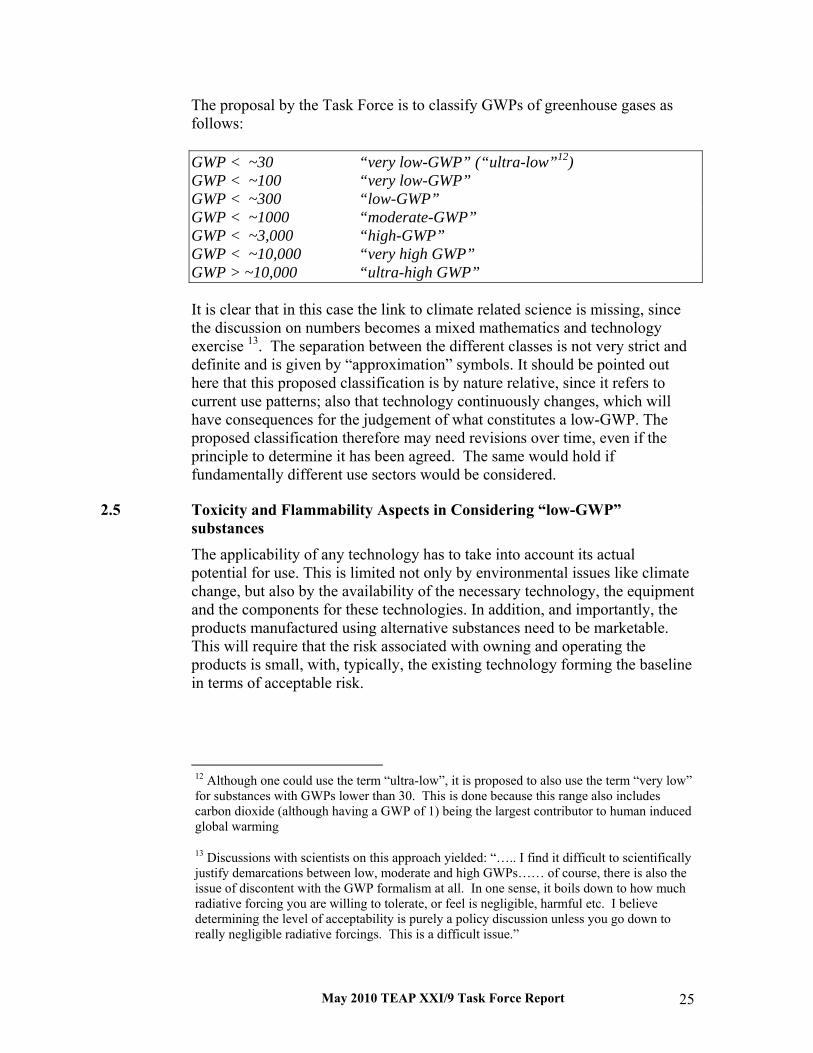
The proposal by the Task Force is to classify GWPs of greenhouse gases as follows: GWP < ~30 “very low-GWP” (“ultra-low”12) GWP < ~100 “very low-GWP” GWP < ~300 “low-GWP” GWP < ~1000 “moderate-GWP” GWP < ~3,000 “high-GWP” GWP < ~10,000 “very high GWP” GWP > ~10,000 “ultra-high GWP” It is clear that in this case the link to climate related science is missing, since the discussion on numbers becomes a mixed mathematics and technology exercise 13. The separation between the different classes is not very strict and definite and is given by “approximation” symbols. It should be pointed out here that this proposed classification is by nature relative, since it refers to current use patterns; also that technology continuously changes, which will have consequences for the judgement of what constitutes a low-GWP. The proposed classification therefore may need revisions over time, even if the principle to determine it has been agreed. The same would hold if fundamentally different use sectors would be considered.
2.5 Toxicity and Flammability Aspects in Considering “low-GWP” substances The applicability of any technology has to take into account its actual potential for use. This is limited not only by environmental issues like climate change, but also by the availability of the necessary technology, the equipment and the components for these technologies. In addition, and importantly, the products manufactured using alternative substances need to be marketable. This will require that the risk associated with owning and operating the products is small, with, typically, the existing technology forming the baseline in terms of acceptable risk.
12 Although one could use the term “ultra-low”, it is proposed to also use the term “very low” for substances with GWPs lower than 30. This is done because this range also includes carbon dioxide (although having a GWP of 1) being the largest contributor to human induced global warming
13 Discussions with scientists on this approach yielded: “….. I find it difficult to scientifically justify demarcations between low, moderate and high GWPs…… of course, there is also the issue of discontent with the GWP formalism at all. In one sense, it boils down to how much radiative forcing you are willing to tolerate, or feel is negligible, harmful etc. I believe determining the level of acceptability is purely a policy discussion unless you go down to really negligible radiative forcings. This is a difficult issue.”

May 2010 TEAP XXI/9 Task Force Report 26
Against this background, two important additional characteristics are to be taken into account when considering in particular “low-GWP” substances, i.e., toxicity and flammability. Toxicity and flammability are characteristics of substances which are assessed and classified against benchmarks that evolve over time as new technology mitigates flammability and toxicity risk and as the risk of climate change is balanced against product risk. Depending on the classification, the use of substances both in production as well as, in certain cases, in the final product might be severely restricted, requiring changes to production process and product, which can be costly and/or reduce the energy efficiency of a product. These changes and restrictions can not only make a product unattractive as compared to its peers using other technologies, they might also increase its energy consumption considerably and therefore reduce or reverse the environmental impact of choosing a low-GWP technology. If toxic substances cannot be applied under certain circumstances or in certain types of products, it may limit the selection of available substances and may lead to the application of substances with GWPs higher than a certain minimum value. Flammability is a more complicated issue. If moderately to low flammability would be required (and e.g., the application of CO2 is no option) it could well be that substances have to be applied such as HFCs or HFC mixtures with GWPs higher than 500-600 in typical commercial applications. This would then currently be the lowest technically feasible GWP option but would not necessarily be classified as “low-GWP”. In specialty applications such as military, civil aviation, etc., it may well be that GWPs of 1000 to 3800 (or even higher) would need to be used, which may represent the lowest possible GWP for that specialty use, but would not be considered “low-GWP.” Moderately flammable substances (not taking into account ammonia or unsaturated HFCs) would have GWPs in the order of 100-300.

May 2010 TEAP XXI/9 Task Force Report 27
3 Methods and Metrics for Prioritising Investment to Minimise Climate Impacts from Technology Selected to Phase Out ODSs
3.1 Introduction In 2007, Parties to the Montreal Protocol accelerated the HCFC phase-out to: further protect the stratospheric ozone layer while also protecting the climate, and to minimise adverse environmental impact of substitutes and alternatives to HCFCs. Adverse environmental impacts result from chemical emissions from products made with or containing greenhouse gases and from greenhouse gas emissions from energy used to power the manufacturing and product operation. Actions to minimize adverse environmental impact are consistent with the Vienna Convention14 and Decisions and Declarations under the Montreal Protocol.15 Methods and metrics can identify and quantify the benefits of technology superior in protecting ozone and climate. That information alone is not enough to transform markets. The results depend on the accuracy and completeness of the input data, the appropriateness of assumptions and the sophistication of the model. Results that are highly sensitive to inputs should not be extrapolated beyond the boundaries of those assumptions. Rather than considering ‘lifecycle costs versus lifecycle savings’, often investors only concentrate on ‘first costs versus lifecycle savings’. This can be for any of a number of reasons: a. Because they do not plan to own the product/equipment/facility long
enough to recover the energy savings,
b. Because they will lease the product/equipment/facility for a period too short to be the beneficiary of the energy savings from investment they undertake,
c. Because they cannot finance the added cost, and 14 Article 2(2)(b) of the Vienna Convention requires “…appropriate policies to control, limit reduce or prevent human activities under their jurisdiction or control should it be found that these activities have or are likely to have adverse effects…” Article 1, ¶ 2 of the Vienna Convention defines adverse effects as “…changes in the physical environment or biota, including changes in climate, which have significant deleterious effects on human health or on the composition, resilience and productivity of natural and managed ecosystems, or on materials useful to mankind.
15 Decision V/8 requires Parties to consider ODS substitutes in light of their environmental impacts, Decision VI/13 directs TEAP to consider how available alternatives to HCFCs compare with respect to factors such as energy efficiency and total global warming impact, the 1998 “Declaration on Hydrochlorofluorocarbons (HCFCs), Hydrofluorocarbons (HFCs) and Perfluorocarbons (PFCs)” urged all Parties to take into account global-warming potential so that the use of alternatives with a high contribution to global warming should be discouraged, (not an issue since they have not been accepted)
May 2010 TEAP XXI/9 Task Force Report 28
d. Because they only have a business model which is focused on short-term profits.
Consumers may not appreciate which products, equipment or facilities are made with or contain greenhouse gases and may not realise when alternatives are available with lower carbon footprints. This is particularly the case when only lifecycle16 assessments can make appropriate comparisons. In most countries the price of products/equipment and the energy they consume does not account for the adverse impact of carbon emissions. There has been little incentive to commercialise low-GWP alternatives and substitutes. The Parties to the Montreal Protocol and the Executive Committee of the Multilateral Fund for the Implementation of the Montreal Protocol (MLF) have the obligation to finance the agreed incremental costs of the phase-out of HCFCs by Article 5 Parties at the pace necessary for their compliance. There may still be an opportunity to simultaneously finance the additional costs of avoiding emissions of high-GWP HFCs. MLF projects potentially could include both redesign of equipment presently made-with or containing HCFCs as well as the upgrading of manufacturing facilities in Article 5 countries so that low-GWP alternatives to HCFCs can be used. With moderate additional effort, such conversion projects can possibly achieve the dual objective to simultaneously reduce the emissions of high GWP gases and improve the energy efficiency. Additional funding mechanisms could provide means necessary beyond the MLF support to achieve significant synergies from a co-ordinated approach. In applications like solvent use and fire protection, the climate impact of substitutes and alternatives to HCFCs is typically only a consequence of the direct emissions of greenhouse gas (GHG) chemicals because the associated energy use is very small. However, in the case of refrigerants and thermal insulating foam, the climate impact arises from both the direct emissions of GHG refrigerants and foam blowing agents and from the indirect emissions of fuel used to power air conditioning and refrigeration or to heat/cool insulated spaces. The climate impact of all insulation types includes the embedded (or embodied) greenhouse gas emissions arising from manufacture (including energy use), the direct emissions of greenhouse gases contained in the insulation and the indirect emissions of fuel used to heat/cool spaces insulated by these materials. Highly emissive uses of high-GWP refrigerants can account for a third or more of total HFC GHG emissions while highly contained low-GWP refrigerants account for an insignificant portion of HFC GHG energy emissions. For example, operation of vehicle AC in the United States consumes 6% of motor fuel, and associated GHG refrigerant emissions
16 See later for more detail about lifecycle assessment

May 2010 TEAP XXI/9 Task Force Report 29
have the carbon equivalence of 2% of U.S motor fuel use more, making a total contribution from US vehicle AC equivalent to 8% of GHG emissions from all US motor fuel use whereas in climates such as India, with long hot and humid seasons and traffic congestion, the motor fuel consumption from operating mobile air conditioners (MACs) can be up to 20%17. Direct emissions in very hot climates like in India are also greater by as much as 3% due to higher average refrigerant pressures in systems operating at higher average ambient conditions. These higher ambient temperatures may also result higher lifetime refrigerant emissions due to material degradation in the hoses and seals.
3.2 Methodology for Estimating Refrigerant, Foam Blowing, and Halon Banks and Emissions The 2005 IPCC Special Report on HFCs and PFCs (SROC)18 determined that impacts on climate of all chlorinated, brominated, and fluorinated substances have to be taken into account. Due to the significant time lag between manufacturing and emissions of products containing ozone depleting and greenhouse gas substances, modelling is necessary to estimate and understand the evolution of atmospheric concentrations of these substances19. The IPCC 2006 Guidelines for National Greenhouse Gas Inventories20 proposed several methods. The “Tier2a” is a bottom-up method based on in-depth review of sales of all types of equipment and products containing ODS and GHG refrigerants, foam blowing, and fire fighting substances and using frequently updated emission factors. Every four years, the Montreal Protocol Assessment Panels integrate the latest information on ODS banks and emissions using information from peer-reviewed publications and the, regular inventory updates by TEAP and its TOCs of all refrigerants, blowing agents, and halons in use. Those results are essential to evaluate progress made by the portion of replacement of ODSs by HFCs and progress that can be made by replacing ODS (or high GWP substances)by low-GWP substances. 17 L. Chaney (National Renewable Energy Laboratory, USA), K. Thundiyil, S. O. Andersen (U.S. Environmental Protection Agency, USA) and S. Chidambaram and Y. P. Abbi (The Energy Resources Institute, India), "Fuel Savings and Emission Reductions from Next-Generation Mobile Air Conditioning Technology in India", National Renewable Energy Laboratory, Golden Colorado, January 2008.
18 Andersen, S. O., Ashford P., Atkins, P., Campbell N., Clodic D., Devotta S., Godwin, D., Harnisch J., Ko, M., Kocchi, S., Kuijpers, L., Madronich S., Metz, B., Meyer, L., Moreira, J., R., Owens, J., Peixoto R., Pons, J., Pyle J., Rand S., Shende, R., Shepherd, T., Sicars, S., Solomon, S., Velders G., Verdonik, D., Wickham, R., Woodcock A., Wright, P., Yamabe, M., IPCC-TEAP Special Report: Safeguarding the Ozone Layer and the Global Climate System (SROC), 2005.
19 TEAP, Report of the Task Force on Emissions Discrepancies, October 2006.
20 Edited by S. Eggleston, L. Buendia, K. Miwa, T. Ngara, and K. Tanabe, Institute for Global Environmental Strategies; Hayama Kanagawa, Japan, 2006.
May 2010 TEAP XXI/9 Task Force Report 30
3.3 Single and Multiple Factor Environmental Performance Metrics
A wide range of metrics has been developed to measure relevant environmental performance of alternative competing technologies. Some metrics, like ODP and GWP, express the potential ozone-depleting or climate impact of a chemical with respect to a normalised baseline and thus measure a single environmental factor. For example, ODP is expressed relative to the normalised baseline of CFC-11 (set at one), while GWP is expressed relative to the normalised baseline of CO2 (set at one for all time horizons, see Chapter 2 for further detail). The most sophisticated and complete analysis considers all environmental impacts, including but not limited to GHGs emissions over the life-cycle of the product, energy “embodied” in the materials to build the factories and fabricate the components, transportation of raw materials and finished goods, as well as chemical emissions at the time of product recycle or disposal and the energy required for that recycle or disposal12.
3.3.1 Ozone-Specific – Single Factor
Ozone-Depletion Potential (ODP) measures the destructive potential of a particular chemical on stratospheric ozone relative to the depletion caused by an equal amount of the reference chemical CFC-1121. ODPs are normally calculated assuming steady state conditions with constant emissions and are not dependent on time (time dependent ODPs can also be calculated)22. Technologies depending on substances controlled by the Montreal Protocol and un-controlled substances with ODP>0 should be avoided. Production and consumption of ODSs controlled by the Montreal Protocol, with the current exception of HCFCs, methyl bromide, and methyl chloroform which are not yet phased out, is not permitted after phase-out unless authorised as a continuing Essential Use or Critical Use by the Parties to the Montreal Protocol.
21 Wuebbles, D. J., Chlorocarbon emission scenarios: Potential impact on stratospheric ozone, J. Geophys., Res., 88, 1433-1443, 1983. WMO, Scientific Assessment of Stratospheric Ozone: 1989, World Meteorological Organization Global Ozone Research and Monitoring Project – Report No. 20, Geneva 1990. WMO, Scientific Assessment of Stratospheric Ozone: 1991, World Meteorological Organization Global Ozone Research and Monitoring Project – Report No. 25, Geneva 1992
Solomon, S., Mills, M. J., Heidt, L. E., Pollock W. H., Tuck, A. F., On the evaluation of ozone depletion potentials, J. Geophys. Res., 97, 825-842, 1992. Solomon, S., Albritton, D. L., A new analysis of time-dependent ozone depletion potentials, Nature, 357, 33, 1992.
22 See Solomon and Albritton, 1992 cited in footnote 19.
May 2010 TEAP XXI/9 Task Force Report 31
3.3.2 Climate-Specific – Single Factor
3.3.2.1 Global-Warming-Potential (GWP)
Global warming potential (GWP) measures the climate impact of a greenhouse gas emission for a specified time interval relative to the impact of the CO2 reference chemical emission over that same time interval. The prominent example of single-factor GWP climate regulation is the EC MAC Directive that phases out between 2011 and 2017 the sale in the European Union of new automobiles with air conditioning systems using refrigerants with GWP > 150. For more detail, see Chapter 2. 3.3.2.2 Product Energy Efficiency
Product Energy Efficiency measures the electricity or energy use for a particular time interval or other unit of measure such as the energy service rendered. For cars, it is typically expressed as the quantity of fuel consumed per distance travelled (litres of fuel per 100 kilometres driven) or as distance travelled per quantity of fuel (kilometres per litre). For refrigerators, it is typically expressed as kilowatt-hours per year per unit of volume (e.g. 100 l) and/or in categories of relative energy efficiency. For heating equipment, it is typically expressed as a percentage of the heat value of the fuel available for heating. For air conditioning, it is typically expressed as a seasonally adjusted value for one or more reference climates23. 3.3.2.3 Electricity Carbon Footprint
The Electricity Carbon Footprint measures carbon intensity of the average, time of day, or incremental generation of electric power from the mix of generating sources of the system supplying the power. Power generated from hydroelectric, nuclear, solar, biomass and wind has the lowest carbon footprint (generally accounting only for the energy embodied in the equipment to generate and deliver electricity) while coal has the highest carbon emissions per unit of electricity production. 3.3.2.4 Chemical Nomenclature
Chemical Nomenclature is an unreliable measure of environmental performance, including ozone depletion and climate forcing, because it fails to account for chemical containment, GWP or ODP, offsetting energy efficiency and other environmental, health, safety and economic factors. However, some companies and regulatory authorities restrict chemical use based on nomenclature alone. For example, Denmark prohibits the sale of refrigeration
23 Graedel, T. E., Allenby, B. R., Linhart, P. B., Implementing Industrial Ecology, IEEE Technology and Society Magazine, 18-26, Spring, 1993.
May 2010 TEAP XXI/9 Task Force Report 32
and air conditioning products containing more than 10 kilograms of HFC (a domestic refrigerator typically has between 50 and 150 g of HFC-134a).
3.3.3 Climate-Specific – Multi-Factor
3.3.3.1 Carbon Footprint Offset (CFO)
The Carbon Footprint Offset (CFO) measures the carbon credit necessary for investment to do no harm to climate. For example, companies and individuals can choose to offset climate impact of HFCs that replace HCFCs by purchasing credits equal to the direct forcing from chemical emissions and indirect forcing from energy use over the life of the products. 3.3.3.2 Total Equivalent Warming Impact (TEWI)
Total Equivalent Warming Impact (TEWI) measures and combines the climate impact of the direct refrigerant emissions and indirect greenhouse emissions from fuel use. The TEWI metric does not measure the greenhouse gas emissions from manufacturing materials, transportation of raw materials and final product, atmospheric degradation products from refrigerant leaks, and disposal or recycling of the product.24 The TEWI methodology was developed to address all major refrigerant, foam insulation and solvent applications. Experts from the industry, government and academia contributed and refined baseline technologies for each sector and alternative technology options to be compared.25 Some analysts in the automotive sector use this metric to assess the impact of mobile air conditioning on the environment.
24 Total Equivalent Warming Impact (TEWI) was developed by Steven K. Fischer, James R. Sand, Van D. Baxter and their colleagues at U.S. Department of Energy’s Oak Ridge National Laboratory as a contribution to the 1990s work of the Alternative Environmental Acceptability Study (AFEAS) which was a cooperative research activity sponsored by global fluorocarbon manufacturing companies investigating alternatives to ODSs.
25 Fischer S. K., Hughes, P. J., Fairchild, P. D., Kusik, C. L., Dieckmann, J. T., McMahon E. M., Hobday, N., Energy and Global Warming Impacts of CFC Alternative Technologies, sponsored by the Alternative Fluorocarbons Environmental Acceptability Study (AFEAS) and the Department of Energy (DOE), December 1991. Fischer, S.K., Tomlinson, J.J. and Hughes, P.J., “Energy and Global Warming Impacts of Not-In-Kind and Next Generation CFC and HCFC Alternatives” U.S. Dept. of Energy and AFEAS, 1994. Sand, J.R., Fisher, S.K. and Baxter, V., “Energy and Global Warming Impacts of HFC Refrigerants and Emerging Technologies”, Oak Ridge National Laboratory Report (sponsored by the U.S.
Department of energy and the Alternative Fluorocarbon Environmental Acceptability Study), 1997. Papasavva S., Moomaw, W., R., Life Cycle Global Warming Impact of CFCs and CFC-substitutes for Refrigeration, J. Ind. Ecology, V. 1, No 4, 71-91, 1998. Goetzler, W., Dieckmann, J., “Assessment of the Commercial Implications of ASHRAE A3 Flammable Refrigerants in Air-conditioning and Refrigeration Systems”, Arthur D. Little, Inc., ARTI Report: ARTI-21CR-610-50025-01, 2001. AFEAS, found in http://www.afeas.org/tewi.html.

May 2010 TEAP XXI/9 Task Force Report 33
3.3.3.3 Life-Cycle Climate Performance (LCCP)
Life-Cycle Climate Performance (LCCP) is a measure of the total cradle-to-grave climate impact, expressed in terms of energy consumed and GHG emissions, over the life-cycle of the product, including manufacturing, transportation, use and end-of-life recycling or disposal26. The most comprehensive application of LCCP methodology currently is for the evaluation of motor vehicle air conditioning systems to replace HFC-134a refrigerants scheduled for phase-out under the EC MAC Directive and could serve as a template for all other subsectors. This model is described at the end of the chapter. 3.3.3.4 Functional Unit Approach (FUA)
The Functional Unit Approach (FUA) was introduced as a quantitative methodology that, in its first embodiment, compared the climate impacts of one or more thermal insulating foam options, including consideration of direct emissions of foam greenhouse gases, emissions of greenhouse gases from energy use during manufacturing, and greenhouse gas emissions from heating and cooling the thermally insulated space over the life of the building in a way that is intended to make technology comparison possible at the enterprise level.27. The FUA was the first method to make the connection between individual product life cycles and the point of technology investment. This approach formed the basis for the further development of the Muliltilateral Fund Climate Impact Indicator (MCII) by the Multilateral Fund Secretariat to address refrigeration and foam applications. 3.3.3.5 Multilateral Fund Climate Impact Indicator (MCII)
The Multilateral Fund Climate Impact Indicator (MCII) evolved from the Functional Unit Approach and is essentially a simplified version of the LCCP28. Its objective is to allow an early assessment of the climate impact of the planned conversion of a manufacturer of, for example, foam or refrigeration and air conditioning products away from HCFC technology. It
26 Life-Cycle Climate Performance (LCCP) was conceived by Stephen O. Andersen (Co-Chair of the TEAP) and the 1999 TEAP Task Force Report “The Implications to the Montreal Protocol of the inclusion of HFCs and PFCs in the Kyoto Protocol”
27 The Functional Unit Approach (FUA) was developed by Paul Ashford (Co-Chair of the TEAP Foams Technical Options Committee) and colleagues at Caleb Management Services under contract to the MLF. Prioritization of HCFC Phase-out Technologies to Minimize other Impacts on the Environment, United Nations Program, UNEP/OzL.Pro/ExCom/57/59, 3 March 2009.
28 Prioritization of HCFC Phase-out Technologies to Minimize other Impacts on the Environment, (Decision 57/33 and Paragraph 147 of the report of the 58th Meeting of the Executive Committee, UNEP/OzL.Pro/ExCom/59/51, 19 October, 2009.

May 2010 TEAP XXI/9 Task Force Report 34
can be used to guide the manufacturer and the country in the technology selection with an approximate up-front assessment of the impact the project will have on the GHG emissions inventory of a country and where significant climate benefits are indicated, whether to approach sources such as the CDM for funding parts of the conversion. The MCII uses country-specific data on climate as well as specific CO2 emissions in energy production (defined as carbon intensity of the electric production). Based on a set of input data, a qualitative ranking of alternatives to HCFC technology is provided based on a quantitative calculation of the climate forcing characteristics of the HCFC and the alternative technology. This approach has advantages in its applicability to situations where only limited data will be available at the time of the technology selection. The MCII estimates the chemical and fuel use GHG emissions from the manufacture and operation of products that are alternatives and substitutes to HCFC technologies29. The result is a ranking with specific percentage disadvantage in energy efficiency compared with the best solution for a certain annual climate profile30. The methodology takes into consideration four distinct parameters but does not account for service emissions over the life-cycle of the product:
1. The number of units produced annually;
2. The amount of ODS used for each unit of production;
3. Basic characteristics such as refrigeration capacity or foam thickness; and
4. The portion of total production exported.
3.3.4 Environmental – Multi-Factor
The Life-Cycle Assessment (LCA) describes any method that attempts to measure all environmental impacts over the complete product cycle. The literature began with “cradle-to-grave,” then expanded to incorporate recycling “cradle-to-cradle,” then expanded further to consider “zero waste,” “one hundred percent recycle,” and for climate “carbon neutral” or “carbon negative” footprint. LCA can be considered as the only truly multi-faceted environmental assessment technique when it incorporates natural resource scarcity, air and water pollution, stratospheric ozone depletion, climate
29 UNEP/OzL.Pro/ExCom/59/51 (November 2009).
30 UNEP/OzL.Pro/ExCom/60/49

May 2010 TEAP XXI/9 Task Force Report 35
change, persistent and bio-accumulating toxins, and genetic effects, among others.31
3.4 Conclusions The ultimate choice of technology to phase-out HCFCs will be based on ozone depletion and also climate impact, health, safety, affordability and availability, as Decision XIX/6 requires. Choosing the lowest GWP substance in the technology replacing HCFCs may not always be the optimum approach because the GHG emissions from product manufacturing and product energy use often dominate the life-cycle carbon footprint. Furthermore, analytical results are only as good as the accuracy and completeness of the input data, the appropriateness of assumptions and the sophistication of the model. When available, LCCP calculations are the most comprehensive method to determine the direct and indirect greenhouse gas emissions at the product level. However, LCCP models need more development to be transparent, adaptable to local climate and electricity carbon intensity situations. In particular, the models must be adaptable to differences in parameters between developed and developing countries. When LCCP models are not available, appropriate, or the necessary data to apply them are not yet available, other methods and metrics will be useful.
31 GaBi, 2008. Available at http://www.gabi-software.com/. Boustead, 2007. Available at http://www.boustead-consulting.co.uk/. UNEP, The Life Cycle Initiative, International Life Cycle Partnership for a sustainable world, Available at http://lcinitiative.unep.fr/ http://lcinitiative.unep.fr/. ISO 14040 (2006): Environmental management - Life cycle assessment -Principles and framework, International Organisation for Standardisation (ISO), Genève. ISO 14044 (2006): Environmental management - Life cycle assessment -Requirements and guidelines, International Organisation for Standardisation (ISO), Genève.

May 2010 TEAP XXI/9 Task Force Report 36
Annex to chapter 3
The GREEN-MAC-LCCP©32 The Global Refrigerants Energy & Environmental-Mobile Air Conditioning-Life Cycle Climate Performance (GREEN-MAC-LCCP©) model is hosted by the U.S. Environmental Protection Agency website: www.epa.gov/cppd/mac. The GREEN-MAC-LCCP© methodology accounts for: 1) all direct GHG refrigerant emissions from refrigerant manufacturing and transportation, vehicle assembly, operation, service, and end-of-life (EOL) MAC system disposal and recycling; 2) all indirect GHG emissions from fuel use during manufacturing, use and EOL; and all embodied (cradle-to-grave) energy and GHG emissions of all materials and components associated with the production, use and disposal of alternative refrigerants and MAC systems. This model calculates the climate impact per vehicle or per kilometre driven as well as the total CO2 equivalent impact considering the vehicle fleet size by region and by year. Typical analysis uses standard input data and assumptions for the energy embodied in production of refrigerants and air conditioning system components, and for climate and driving habits of specific locations. The GREEN-MAC-LCCP© is now an SAE International Test Standard and will be the global metric for vehicle climate performance for MAC regulations and possibly for quantifying GHG emissions in carbon trading. GREEN-MAC-LCCP demonstrates clearly that detailed and global models can be developed for certain applications if the relevant stakeholders cooperate. This can create significant positive benefits and high degree of certainty when selecting alternative technologies to HCFC or even to other high GWP gases for the manufacturing of specific products. However, currently available LCCP tools are less appropriate as predictive tools for stationary air conditioning, refrigeration, and thermal insulating foam applications where there are significant variations in product design, application or geographic areas of use. In these instances, other methods and metrics may be required to make assessment of climate impacts, particularly at enterprise and programme level.
32 Papasavva, S., Hill, W. R., Brown, R. O., 2008. GREEN-MAC-LCCP©: A Tool for Assessing Life Cycle Greenhouse Emissions of Alternative Refrigerants. SAE Transactions, 2008-01-0829, April 2008. Hill, W. R., Papasavva, S. Life Cycle Analysis Framework; A Comparison of HFC-134a, HFC-134a Enhanced, HFC-152a, R744, R744 Enhanced, and R290 Automotive Refrigerant Systems. SAE paper 2005-01-1511, SAE Technical Series Paper, 2005. Papasavva, S., Luecken, D. J., Waterland, R. L., Taddonio, K. N., Andersen, S. O. Estimated 2017 Refrigerant Emissions of 2,3,3,3-tetrafluoropropene (HFC-1234yf) in the United States resulting from Automobile Air Conditioning. Environ. Sci. Technol., 2009, 43, 24, 9252-9259. Papasavva, S., Andersen, S. O. GREEN-MAC-LCCP© The Life-Cycle-Climate Performance Metric for Mobile Air Conditioning Environmental Superiority that Levels the Playing Field and Facilitates Technology Choice. Submitted for publication in Environmental Progress & Sustainable Energy Journal, October 2009.

May 2010 TEAP XXI/9 Task Force Report 37
4 Domestic Refrigeration
4.1 Background Approximately 100 million domestic refrigerators and freezers are produced annually. Storage volumes range from 20 to 850 litres per unit. A typical product contains a factory-assembled, hermetically sealed vapour-compression refrigeration system employing a 50 to 250 Watt induction motor and containing 50 to 250 grams of refrigerant. The age distribution of installed products is extremely broad with an estimated median age of 15-19 years at retirement. The long product life and high volume annual production combine for an estimated global installed inventory of 1500 to 1800 million units.
4.2 Refrigerant Options Conversion of all new production domestic refrigerators and freezers from the use of ozone-depleting refrigerants is complete. Non-Article 5 Parties completed conversions by 1996, Article 5 Parties by 2008. The conversion of existing units to alternative refrigerants has not been widely pursued. .
4.2.1 New Equipment Options
About 63 percent of current new production refrigerators employ HFC-134a refrigerant. About 36 percent employ hydrocarbon refrigerants. The remaining 1 percent employs either HFC-152a or HCFC-22. Isobutane (HC-600a) is the hydrocarbon refrigerant commonly used. There are substantial regional differences; the majority of European refrigerators is being produced with HC-600a where other regions have no or very little use of HC-600a. Blends of HC-600a and HC-290 are used in some cases to avoid investment to retool compressors. Both HFC-134a and HC-600a deliver comparable energy efficiency with design variation providing more difference than the refrigerant selection. Two industry dynamics of interest are second-generation migration from HFC-134a to HC-600a and preliminary suggestions of the use of low-GWP unsaturated fluorocarbons to replace HFC-134a. Migration of new production refrigerators from HFC-134a to HC-600a is motivated by global warming considerations. This conversion is complete in Japan and has been initiated in other countries such as the U.S. and Brazil. It is predicted that at least 75 percent of global new refrigerator production will use hydrocarbon refrigerants in 10 years. Product codes and standards changes required to achieve this estimate are in progress. The cited timing assumes no government intervention to accelerate the trend. Chemical manufacturers developed low-GWP unsaturated HFC compounds for automotive air conditioning use. Theoretically, HFC-1234yf has the potential for comparable energy efficiency to currently used refrigerants. Long-term reliability expectations for domestic refrigeration are still more

May 2010 TEAP XXI/9 Task Force Report 38
demanding than for vehicle AC. Significant assessments are required to establish this as a viable domestic refrigeration alternative.
4.2.2 Not-In-Kind Alternative Technologies
Alternative refrigeration technologies continue to be pursued for applications with unique drivers such as portability or lack of access to electrical energy distribution networks. In the absence of unique drivers such as these, no identified technology is cost or efficiency competitive with conventional vapour-compression technology for mass-produced equipment. Each would require significant capital investment to facilitate for mass production capability. Alternative technologies of interest for niche application opportunities include: Stirling cycle, including trans-critical CO2; absorption; thermoelectric; and magnetic.
4.2.3 Service of Existing Equipment
Field service procedures typically use originally specified refrigerants. Field conversion to non-ODS refrigerants has received little interest or success. Non-Article 5 countries completed new production conversions more than 15 years ago. The final production products are now approaching the end of their life cycle and service demand for legacy refrigerant is vanishing. In Article 5 countries the service demand for legacy refrigerants is expected to remain strong for at least a decade because of the delayed conversion from CFC-12.
4.2.4 Product Energy Efficiency Improvement Technologies
Relative energy efficiency provides a direct linkage to the global warming potential of refrigeration technology options during use. Energy labelling and energy regulations are widely used to promote improved product energy efficiency. Options to significantly improve product energy efficiency have demonstrated mass production feasibility. Extension of these to all products would yield significant benefit, but requires capital funds. Additional options for significant efficiency improvement presently have limited application. These premium-cost options are restricted to high-end models or require supplemental incentives to proliferate their use at this stage of maturity.
4.2.5 Refrigerant Annual Demand
Domestic refrigeration annual refrigerant demand is not reported but can be estimated with reasonable assumptions. The 2008 estimated global demand was 15 ktonnes: 63 percent HFC-134a, 36 percent HC-600a and HC-290, and 1 percent all other types. By 2020 it is estimated HC-600a will be more than 75 percent of the total demand with the balance being HFC-134a. Reasonable predictions for field service refrigerant demand are not available. Crude estimates suggest a 3 to 5 ktonnes annual global demand. Approximately one-half for legacy refrigerant and the remaining one-half for currently used refrigerants. A stable demand trend is expected due to the inherent high inertia of the installed base. Demand is expected to continue for originally

May 2010 TEAP XXI/9 Task Force Report 39
specified refrigerants: primarily CFC-12 for legacy product and either HFC-134a or HC-600a and HC-290 for new production. CFC-12 demand will vanish as legacy products are retired. Mandatory service regulations could promote the use of refrigerant blends for service and reduce emissions of ODS refrigerants by eliminating CFC-12 demand. Table 4-1: HCFCs and low-GWP alternatives used in domestic refrigeration
Domestic refrigeration HCFCs used HCFC-22 Percentage HCFCs used globally <<1% % high-GWP alternatives used in sector globally (e.g., HFCs)
63%
Low-GWP alternatives in use HC-600a Product cost: low-GWP vs. HCFC Comparable to HFC Energy efficiency: low-GWP vs. high GWP Comparable to HFC Market penetration of low-GWP in developed countries
36% global and growing
Market penetration of low-GWP in developing countries
36% global and growing
Energy efficiency of low-GWP vs. high GWP normally used
Comparable
What low-GWP may be commercialized? N/A Time scale for commercialization N/A


May 2010 TEAP XXI/9 Task Force Report 41
5 Low-GWP Alternatives for Commercial Refrigeration 5.1 Background
Commercial refrigeration is characterised by a wide variety of equipment and refrigerating capacities, which vary from some hundred Watts to 1.5 MW. Low-GWP alternatives for replacement of HCFC-22 and also R-502 (azeotropic blend of CFC-115 and HCFC-22) have been studied and tested since 1992 in Europe and 2000 in Japan. CO2 secondary system has retained significant attention in the US since 2005. HCFC-22 represents the largest refrigerant bank in commercial refrigeration and is used at all levels of temperatures. Technical solutions for replacement of HCFC-22 by low-GWP refrigerants vary depending on the three main groups of refrigeration systems: stand-alone equipment, condensing units and centralised systems. Even for those, solutions may be different depending on size of the supermarket. Stand-alone equipment are systems where all refrigeration components are integrated and, for the smallest types, the refrigeration circuit is entirely brazed or welded. Stand-alone equipment, including freezers, vending machines, and beverage coolers, are extensively used in many Article 5 countries. The current dominant refrigerant is HFC-134a (GWP = 1440). Low-GWP alternatives have been used for several years in commercial freezers and vending machines. The most studied, tested and commercialised alternatives for this type of equipment are hydrocarbons (mainly propane) and CO2. Condensing units exhibit refrigerating capacities ranging typically from 1 kW to 20 kW. They are composed of one (or two) compressor(s), one condenser, and one receiver assembled into a so-called “condensing unit”, which is located external to sales area. Condensing units are typically installed in specialty shops such as bakeries, butcher shops, and convenience stores. In most A5 countries, the use of systems employing condensing units is very extensive. Low-GWP alternatives are also hydrocarbons and CO2, but ammonia is also a candidate. The dominant refrigerants to replace HCFC-22 are currently HFC-134a and R-404A. Centralized systems are the preferred option in supermarkets, they operate with racks of compressors installed in a machinery room (see figure 5-1) and the refrigerant goes in the liquid phase from the machinery room to the display-cases and cold rooms, and returns in the vapour phase to be compressed by the compressors.

May 2010 TEAP XXI/9 Task Force Report 42
Table 5-1: HCFC in use in the commercial sector and low-GWP alternatives
Commercial refrigeration
Condensing units
Centralised systems
Stand alone
% HCFCs available in subsector bank in the total
52% 48%
HCFCs used HCFC-22 HCFC-22 No HCFC Percentage HCFCs used globally
60% 60%
% high-GWP alternatives used in sector globally (e.g., HFCs)
15% 15%
Low-GWP alternatives in use
CO2 HC-290 Amm/CO2 HC
Product cost: low-GWP vs. HCFC
+15% +5% 0-15% 0-15%
Energy efficiency: low-GWP vs. high GWP
0/-15% 0/+5% Up to 5% Up to 5%
Market penetration of low-GWP in developed countries
1-2% 3-5% 2-5% <1%
Market penetration of low-GWP in developing countries
? ?
Energy efficiency of low-GWP vs. high GWP normally used
0/-15% 0/+5% comp. to 404A
Up to 5% improvement comp. to 404A
What low-GWP may be commercialized?
R-717 ? ? ?
Time scale for commercialization
N/A N/A N/A N/A
A centralized system is the preferred option in supermarkets, they operate with racks of compressors installed in a machinery room (see Figure 5-1) and the refrigerant goes in liquid phase from the machinery room to the display-cases and cold rooms and return in vapour phase to be compressed by the compressors.
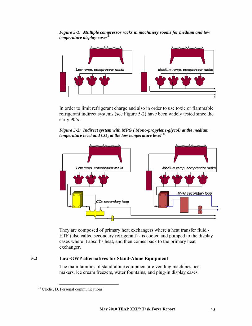
May 2010 TEAP XXI/9 Task Force Report 43
Figure 5-1: Multiple compressor racks in machinery rooms for medium and low temperature display-cases33
In order to limit refrigerant charge and also in order to use toxic or flammable refrigerant indirect systems (see Figure 5-2) have been widely tested since the early 90’s . Figure 5-2: Indirect system with MPG ( Mono-propylene-glycol) at the medium temperature level and CO2 at the low temperature level 32
They are composed of primary heat exchangers where a heat transfer fluid - HTF (also called secondary refrigerant) - is cooled and pumped to the display cases where it absorbs heat, and then comes back to the primary heat exchanger.
5.2 Low-GWP alternatives for Stand-Alone Equipment
The main families of stand-alone equipment are vending machines, ice makers, ice cream freezers, water fountains, and plug-in display cases.
33 Clodic, D. Personal communications
May 2010 TEAP XXI/9 Task Force Report 44
For food and beverages kept at temperatures ranging from +1 °C up to 10 °C, HFC-134a can be replaced by HC-600a and HC-290, and has been replaced in some families of equipment where generally the refrigerant charge is less than 150 g for most manufacturers. However, some European brands have commercialized equipment with hydrocarbon charges up to 1 kg. For other companies CO2 is the preferred refrigerant choice. For all replacement of HFC or HCFC by hydrocarbons, if the replacement is done on an equivalent basis of heat exchange surface and compressor efficiency, the overall energy efficiency of a hydrocarbon system is identical to the base line. Energy improvements can be made regardless of the refrigerant, and so comparisons have to be made on an equal design basis. When replacing HCFC-22 or HFCs by CO2, the normal discussion point is: what is the performance of the CO2 system compared to the baseline when the outdoor temperature is higher than 25°C or 30°C. It has been verified that for an equivalent design (identical heat exchange surface areas and identical compressor efficiencies), CO2 in a transcritical cycle is less efficient than the usual condensing refrigerants. However, it should be noted that a number of technical improvements have taken place due to competition between CO2 and the reference refrigerants.
Ice Cream freezers For ice cream freezers in Europe, the switch from HFC refrigerant to propane (HC-290) is steady. A limited number of safety precautions have been implemented in hydrocarbon freezers and the equipment prices have not significantly changed. The market share of those hydrocarbon commercial freezers is significant in Europe and increases every year. Ice Machines A large number of ice machines are installed in restaurants, bars, and hotels. The global market is dominated by the US, and so the main refrigerant in use is HFC-134a. Ice machines operating with CO2 or propane have been developed with a limited market share. Note that for CO2, the efficiency is arguable in hot climates. Vending Machines The cooling capacity of vending machines is about 600 W for rapid cooling of cans. A CO2 system has been developed and to facilitate maintenance it is installed inside a plug-in/pull-out cassette. Its energy efficiency, as measured, is as good as the reference HFC systems up to 32°C ambient temperature. Glass-Door Coolers The most common is the one-door 400-litre type. Since 2000, several thousand units have been installed in Europe using mostly HC-600a and, for

May 2010 TEAP XXI/9 Task Force Report 45
some brand names, HC-290. However, some global companies have chosen CO2 systems for their bottle coolers. Plug-in Display Cabinets The use of plug-in display cabinets is increasing in small and medium size supermarkets. So far, R-404A or HCFC-22 are standard choices in the developing countries, and the refrigerant charge per unit varies from 220 g to 300 g. Especially in Germany and the Northern European countries, plug-in display cabinets operating on HC-290 are gaining market share. Several German supermarket chains now only purchase HC based plug-in cabinets 34. In summary, HFC-134a fulfils the technical constraints in terms of reliability and energy performance for stand-alone equipment. When the high GWP of HFC-134a is considered prohibitive in relation to HFC emissions, hydrocarbon refrigerants or CO2 are the current alternative solutions. In the near future, unsaturated HFCs such as HFC-1234yf could be considered as a tailored solution. The retrofit from HFC-134a to this new refrigerant is expected to be rather simple owing to similar thermodynamic properties, even if long-term reliability has to be assessed.
5.3 Low-GWP Alternatives for Condensing Unit Systems Condensing units are found in many convenience and food specialty stores for cooling a small cold room and one or more display cases. The technology can be considered as a mass production one with standard hermetic compressors and is a widespread option in Article 5 countries. Even in supermarkets, especially in some Article 5 countries, several racks of condensing units are installed side-by-side in small machinery rooms. Condensing units are less energy efficient by far than a well-designed small-centralised system, but condensing units are chosen for initial cost reasons, easiness of installation, and are found ready to install. The cooling capacities vary from 5 to 20 kW mostly at medium temperature and the refrigerant charges vary from 1 to 5 kg for HCFCs or HFCs. HCFC-22 is still the most used refrigerant in the US and in all Article 5 countries. New equipment can use HFC-134a, HCFC-22, R-404A, R-407C, R-507, other HFC and HCFC blends, HC refrigerants, and CO2. Condensing units constitute the most difficult family for an uptake of low- GWP alternatives because the market is driven by cost and the design is
34 Rhiemeier, J.-M.; Harnisch, J.; Kauffeld, M.; Leisewitz, A.: Comparative Assessment of
the Climate Relevance of Supermarket Refrigeration Systems and Equipment. Environmental Research of the Federal Ministry Of The Environment, Nature Conservation And Nuclear Safety Research Report 206 44 300, UBA-FB 001180/e, March 2009

May 2010 TEAP XXI/9 Task Force Report 46
simple with HCFC-22. Condensing units are wide spread and can be installed in any climate. Up to now, no compressor manufacturer or OEM has taken the decision to develop large condensing units working with CO2 owing to cost reasons and cooling capacity guarantee, without even considering energy efficiency. For hydrocarbons, the issue remains safe installation and maintenance. Contrary to stand-alone equipment, the design is not an overall installation design, and in fact a condensing unit is an off-the-shelve spare part integrated by a contractor on any type of small installation anywhere in the world. So the safe design is split between the condensing unit design and the complete installation design. Only in countries where regulations discourage the use of HFCs can condensing units using HCs be easily found. R-404A is the leading choice for cost reasons - the condensing units using this refrigerant are cheaper compared to HFC-134a units of the same cooling capacity because of smaller compressors. Nevertheless in hot climates and for medium temperature applications, HFC-134a is used owing to its better energy performance at high ambient temperatures compared to R-404A. It has to be noted that new designs emerged using ammonia. The Sanden Company, which is a significant stakeholder in Japanese commercial markets, proposes a design shown in Figure 5-3 for small capacities corresponding to condensing units. Figure 5-3: Two stage small cascade system with ammonia and CO2
The design seems complicated but utilises the good efficiency of ammonia at medium evaporating temperature and guarantees the efficiency of CO2 at the low temperature. Moreover, the ammonia charge is limited. The near future will show whether the design will be adopted by commercial chains. It should be noted that, as with stand-alone equipment, this report does not provide any details on the use of unsaturated HFCs, such as HFC-1234yf or HFC-1234ze,

May 2010 TEAP XXI/9 Task Force Report 47
because no lessons learnt from the field or laboratory tests have been disclosed up to now.
5.4 Low-GWP Alternatives for Supermarket Systems For large supermarkets, the dominant design is the so-called centralised system where all the compressor racks are installed in a single machinery room. The size of centralised systems can vary from refrigerating capacities of about 20 kW to more than 1 MW depending on the size of the supermarket. The refrigerating capacities are generated by independent racks of compressors at two main levels of evaporating temperatures, -40 / -35°C for frozen food (and ice-creams), and -15 / -10°C for fresh food (dairy, meat). Even though this has not been the choice until now, refrigerants adapted to each of the 2 levels of temperature seems to be the more appropriate solution for the future, especially when favoring low-GWP options, because CO2 is well adapted to the low evaporating temperature if condensation takes place between -5 and +10 °C. CO2 can be the preferred choice at the low-temperature level in a cascade design, but the choice for the medium-temperature level is still under evaluation in developed countries and depends on global warming, costs, and ease of use. In summary, in the medium and long term, CO2 evaporating at the low temperature level of about -35 °C for freezers and condensing between -10 and -5°C seems the most efficient option for low-GWP alternatives. A number of possible designs are associated with this basic choice. For the medium temperature level, the low-GWP options are much less evident. Several options are under evaluation even though hundreds of installations are currently running with hydrocarbons, ammonia or even CO2 at the medium temperature level. Some of the main options are described here. Indirect Systems Indirect systems represent a small market share of new installations. This option was developed in Europe in 1995 and has expanded slowly since. The driver to change from the usual direct expansion systems is the significant reduction in refrigerant charges (75 to 85 %) and a much better refrigerant containment. Energy efficiency has been widely studied and well-designed indirect systems compete with well-designed direct systems. This is especially the case with CO2 at low temperatures. The pumping energy for CO2 is relatively low because CO2 used as a heat transfer fluid is evaporated in the display cases and so the mass flow rate is small and therefore so is the pumping energy consumption. Ammonia, HCs (HC-290 or HC-1270), and CO2 are used as low-GWP refrigerants in refrigerating systems that are completely installed in machinery rooms. Owing to its high latent heat of vaporisation and low liquid density,

May 2010 TEAP XXI/9 Task Force Report 48
the ammonia (R-717) charge can be 10% of the usual HFC refrigerant charge. Such systems can be installed in special machinery rooms with safety features that allow high ventilation rates in case of significant leaks. The same applies to HC refrigerants with charges typically 10% of the direct system HFC reference charge. For safety reasons, the refrigerant circuits are separated into several independent ones, limiting the refrigerant charge of each system (IPCC-TEAP Report 2005). A drawback of indirect systems is related to the necessary insulation of all piping in order to avoid icing and humidity condensation. Valves and pumps can present difficulties for efficient insulation and may become ice blocks with water dripping continuously around the ice blocks. Moreover, for liquid HTF used at the medium-temperature level, quantities are enormous representing several metric tonnes, and possible leaks of HTF are difficult to diagnose especially in the display cases. All those lessons learnt from the existing indirect systems are being tackled by improved designs. Cascading Systems Here, CO2 is not an HTF but a refrigerant used in a cascade system. One design consists of a low-temperature compressor rack with CO2 compressors working at an evaporating temperature around -35°C and a condensing temperature of -12°C, thus keeping the tubing and the components under the 2.5 or 3 MPa pressure thresholds, which are the thresholds of current technologies. Figure 5-4: Hybrid system comprising a CO2 cascade at the low temperature level and a secondary system at the medium temperature level 30
As a consequence, costs are kept identical between a CO2 system and an HFC one. For larger stores (above 2500 m2 sales area) the use of CO2 in a cascade system is even more cost effective owing to smaller pipe dimensions. The condensation of the CO2 low-temperature stage is made by exchanging heat

May 2010 TEAP XXI/9 Task Force Report 49
with the heat transfer fluid used at the medium-temperature stage. The primary refrigerant at the medium temperature can be HFC-134a, R-404A, ammonia, or HCs. For the last two refrigerants, as said before, the special machinery room is outside the building in the open air with safety devices to take care of possible release of refrigerant. Two-stage Centralized CO2 Systems The most up-to-date design of a CO2 refrigeration system employs CO2 both for the LT and MT temperature range. One common design is the one described in Figure 5-4, another has the compressors for the LT-stage cascaded with those for the MT-stage (Figure 5-5). Figure 5-5: All-CO2 centralized refrigeration system 28
This design is becoming popular in Central and Northern Europe cold climates. During times with high outdoor temperatures, i.e. in summer, the CO2 is no longer condensed in the outdoor air cooled condenser due to CO2’s low critical temperature of 32 °C. The energy efficiency is lower than that of a comparable R-404A system during this trans-critical operation. For all the developments described above a number of references have been consulted 35 36 37 38 39 40 41 42.
35 Assawamartbunlue, K., Brandemuehl, M. J., Refrigerant Leakage Detection and Diagnosis for a Distributed Refrigeration System, HVAC Research, Vol. 12, No. 3, July 2006. 36 Bivens, D. and Gage, C., 2004: Commercial refrigeration systems emissions. In the proceedings of the 15th Annual Earth Technology Forum, April 204, Washington, USA.
37 DOE - Energy Conservation Program: Energy Conservation Standards for Refrigerated Bottled or Canned Beverage Vending Machines; Proposed Rule, 10 CFR Part 431, Federal Register / Vol. 74, No. 102 / Friday, May 29, 2009.
38 Girotto, S., Minetto, S. and Nekså, P., (2004): Commercial Refrigeration with CO2 as Refrigerant, Experimental Results, Int. J of Refrigeration, Vol 27 (7), November 2004
May 2010 TEAP XXI/9 Task Force Report 50
5.5 Conclusions For each of the three main sorts of systems described, options with low-GWP refrigerants exist and have already been thoroughly tested for many of them. Nevertheless, so far they are certainly not the dominant options for new equipment except in some Northern European countries - particularly Denmark. For small charged stand-alone equipment, hydrocarbons are a proven technology, but analyses have to be performed on a case by case basis to verify that the safety conditions are always adapted to the usage in the commercial and technical context of each country. For condensing units, the low-GWP alternatives have not gained any significant market share, which is explained by the market constraints of this equipment: a simple, widespread and cheap system to be installed all over the world by contractors having a variety of technical skills. This last constraint implies no possible guarantee for safety (in case of HCs, nor for cooling performances (CO2 in hot climates)). So developments are needed for this family of equipment. For supermarket systems, a variety of designs have been tested with low-GWP alternatives over the past 15 years. Lessons have been learnt from those experiences. Indirect systems are of interest and they can compete in terms of cost and efficiency with direct systems provided the design is good. Indirect systems reduce the charge by 50 to even 90%¨depending on the refrigerant choices. For the low temperature level, CO2 is the recognised best candidate for the future. For medium temperature systems the choice of refrigerant is subject to a number of new developments. The competition between the alternatives includes unsaturated HFCs such as HFC-1234yf, certainly blended with HFCs such as HFC-32, and also ammonia, hydrocarbons and CO2 in cold climates.
39 Haaf, S., Heinbokel, B. and Gernemann, A. 2005: Erste CO2-Kälteanlage für Normal- und Tiefkühlung in einem Schwezer Hypermarket, Die Kälte & Klimatechnik, 2/2005
40 Kauffeld, M., Trends and Perspectives in Supermarket Refrigeration, EU conference to focus on R744 refrigeration, Germany, 2007
41 Kazachki, G. S., Hinde, D. K., Secondary coolant systems for supermarkets, ASHRAE Journal, September 2006.
42 Sawalha, S., Suleymani, A., Rogstam, J., Project 2: CO2 in Supermarket Refrigeration, Project report, Phase 1, 2006.

May 2010 TEAP XXI/9 Task Force Report 51
6 Industrial Refrigeration The large equipment sector, also called “industrial equipment”, covers refrigeration, heat pump and process air conditioning plants in the size range of 100kW and upwards, with operating temperatures ranging from -50oC to +20oC. This does not, however, include large chillers for comfort cooling, which typically use centrifugal compressors operating on a fluorocarbon refrigerant, or centralised supermarket refrigeration systems, which use HCFCs or HFCs.
6.1 Use of HFCs HFCs have not been widely adopted in industrial systems, although they have been used in specific applications from time to time.
6.2 Use of HCFCs In Article 5 countries, where the HCFC phase-out is on a slower time-scale than in the Non-Article 5 ones, the use of HCFC-22 in industrial systems is still very widespread.
6.3 Current or Future Use of Low-GWP substances 6.3.1 Ammonia
Large refrigeration systems predominantly use ammonia as the refrigerant unless there are compelling local reasons to avoid it. The reasons for ammonia’s popularity are the relatively low capital cost for the equipment combined with its excellent operating performance.
6.3.3 Carbon dioxide
There is an emerging trend towards the use of carbon dioxide in industrial systems when direct ammonia systems are not feasible, either in cascade with low charge ammonia or HFC systems, or in two stage systems with heat rejection at supercritical pressures.
6.3.4 Hydrocarbons
In large petrochemical facilities, where the whole facility is engineered to avoid ignition sources, hydrocarbons are sometimes used. In these systems the refrigeration cycle is the same as applied in standard equipment, and its efficiency is generally good. Equipment can be engineered for evaporation temperatures from -50oC to 20oC by selection of the hydrocarbon; wide-glide mixtures of ethane and propane, with up to 20K temperature glide during the evaporation and condensation, have been used to further improve efficiency in auto-cascade systems. Care must be taken to avoid oil foaming in screw and reciprocating compressors, because of the extreme miscibility of the refrigerant in the oil.

May 2010 TEAP XXI/9 Task Force Report 52
6.4 Markets In some countries, for example the United States of America, the industrial sector was slow to shift to CFCs in the post-war era, and so retained a large stock of ammonia equipment. In Europe there was a greater shift away from ammonia from 1970 onward, particularly to the CFC based blend R-502, which was well suited to small, simple packaged systems. The phase-out of CFCs prompted a shift to HCFC-22 in some systems, but for low temperature applications this refrigerant was generally less reliable. In other cases a swift return to ammonia could be observed, but that applied to modern systems, characterised in comparison to traditional ammonia plants as requiring less refrigerant charge, and with a more automated operation. National markets within Europe responded differently to the CFC phase-out. Scandinavian countries, the United Kingdom and the Republic of Ireland returned to ammonia relatively easily. France, Italy and Spain used more HFC equipment in the industrial sector, mainly due to higher levels of bureaucracy associated with ammonia use. In Central Europe, including Germany, Austria and Switzerland there was a marked return to ammonia, but not as quickly or completely as in Northern Europe. However, increased restrictions on HCFC use have encouraged that trend to continue, so that by the turn of the century the use of ammonia was as common in Central Europe as it is further north. In Eastern Europe and in the Russian Federation, older ammonia systems are still commonly in use, however, these are often in poor condition. Some modern facilities have been constructed in India and China using ammonia as refrigerant with the equipment supplied by European or American multinationals. The designs of these facilities conform to European or North American standards but there is a strong need for ongoing training in operation and maintenance of these facilities. Carbon dioxide is most suitable in colder climates where it is easier to make systems as efficient as current installations using different refrigerants. Some further equipment development is required if these systems are to be accepted in warmer climates such as the ones found in southern Europe, southern United States, Latin America and most of Asia. In 2008, a distribution warehouse was commissioned in Denmark, which provided 1500 kW of cooling capacity in chill and freezer storage rooms, and delivered about 1200 kW to a local district heating system from a trans-critical carbon dioxide refrigeration system. Carbon dioxide is very cost effective when applied in this way, together with integrated heating and cooling requirements. If this type of system becomes more common, it would be possible for Article 5 countries that have to move away from HCFCs to avoid conversion to large HFC or ammonia systems, and instead develop carbon dioxide solutions to suit their own specific requirements. Since, in the industrial sector, most users moved from CFCs to either ammonia or HCFCs, but not to HFCs, there is actually no bank of HFC equipment. Users in developed countries now faced with moving from HCFC

May 2010 TEAP XXI/9 Task Force Report 53
equipment due to the phase out are more likely to adopt ammonia, carbon dioxide, or a combination of the two, than they are to move to HFCs. In Article 5 countries it is more likely that HCFC equipment will be retained for as long as possible, and then switched to the ammonia or carbon dioxide alternatives. To achieve this transition there is a need for education and training in the health and safety issues related to working with ammonia and carbon dioxide. The major hurdle is the conversion of existing, valuable training material available in Europe and the United States into the local languages required around the world. Table 6-1: HCFCs and low-GWP alternatives
Industrial systems Industrial refrigeration
Industrial heat pumps
Industrial AC
HCFCs used HCFC-22/ R-403B
HCFC-22/ R-403B
HCFC-22/ R-403B
% HCFCs available in subsector banks/ new build
40/10 10/0 30/0 0/0 50/0 0/0
% high-GWP alternatives used in sector globally (e.g., HFCs) in banks/new build
HFC-134a/ Blends (404A) 5/5 15/20
HFC-134a/ Blends (404A) 60/40 0/0
HFC-134a/ Blends (404A) 10/40 15/20
Low-GWP alternatives in use
Ammonia, carbon dioxide, HCs
Ammonia, carbon dioxide, HCs
Ammonia, Carbon dioxide, HCs
Product cost: low-GWP vs. HCFC
+20/+40/+50 0/NA/NA +50/+100/+50
Energy efficiency: low-GWP vs. high GWP
+20/0/+10 +10/NA/NA +20/0/+10
Market penetration of low-GWP in developed countries
80/10/2% 5%/NA/NA 30/0/10%
Market penetration of low-GWP in developing countries
40/0/0% 0%/NA/NA 10/0/5%
Energy efficiency of low-GWP vs. high GWP normally used
(vs. R-404A) +30/0/+20%
(vs. HFC-134a) +20%/NA/NA
(vs. HFC-134a) +10%/NA/NA
What low-GWP may be commercialized?
Air cycle, Water vapour compression
N/A N/A
Time scale for commercialization
Unknown N/A N/A


May 2010 TEAP XXI/9 Task Force Report 55
7 Transport Refrigeration
7.1 Introduction
Transport refrigeration is a niche market with special requirements in terms of equipment robustness, weight, corrosion resistance, etc. Rigorous testing and performance verification must be carried out in order to permit the systems for field use. In order to ensure food quality and safety, it is imperative that adequate maintenance (spare parts, service personnel) is present along the transport routes. Refrigerant HCFC-22 has been well established in the market for many years. In developed countries, however, HFC refrigerants have been phased in for more than 15 years. Although many components had to be redesigned, the smooth transition was possible because the refrigeration equipment as such did not require major changes. In contrast, natural low-GWP substances require substantial shifts. In some cases, technical constraints have not yet been overcome to produce a low-GWP system that would match the HFC performance.
7.2 Use of HCFCs The main HCFC working fluids utilized in the transport refrigeration sector is HCFC-22.
HCFC-22 and CFC-12 were widely used in the early history of transport refrigeration. R-502 (which contains CFC-115) was introduced in 1962 to overcome high discharge temperatures and oil return problems of HCFC-22 at low temperature operation 43. When CFC-115 had been phased out under the Montreal Protocol, R-502 systems were retrofitted mostly with R-408A or R-402A (which both contain HCFC-22). R-408A was preferred because system components did not require changing. Also mineral oils, when applicable, could have remained in the system. R-402A was used to retrofit R-502 in mid-to-late 90’ in the USA 44, and may still be used in some countries. The use of CFC-12 is limited only to a few cases. In China, for example, CFC-12 utilized in refrigerated railcars is being replaced by HCFC-22 gradually since 2008.
43 Park K. and D. Jung, Thermodynamic performance of R502 alternative refrigerant mixture for low temperature and transport applications, Energy Conversion and Management 48 (2007) pp. 3084-3089
44 Private communication Jeff Berge, Manager R&D, Thermo King Corp., November 2009

May 2010 TEAP XXI/9 Task Force Report 56
Being aware of the phase out deadlines, and having a concern over the use of a refrigerant containing any chlorine, many equipment manufacturers converted from CFCs such as R-502 to HFCs in the 1990’s. There are vast differences in HCFC use among the different transport refrigeration sub-sectors. HCFCs have not been used in intermodal marine containers for about 15 years, favoring HFC-134a and R-404A. Refrigerated railcars have utilized all refrigerants stated previously; however, they are being gradually and definitely replaced by intermodal marine containers even in the Article 5 countries. Today road transport utilizes HCFCs only in Article 5 countries. Although small in terms of banks, HCFC-22 is widespread aboard ships. This sub-sector consists of branches as different as fishing and cruise-shipping, where different technologies can be applied for various purposes. No HCFC-22 has been used in airborne containers, which is a new product segment with a paramount safety concern of air traffic. The equipment lifetime is usually between 10 and 15 years for intermodal marine containers, railcars and road vehicles, and 20 to 25 years for equipment aboard vessels. Transport refrigeration serves primarily the cold food chain, which has to guarantee food quality and safety. To a smaller extent it also includes the transport of pharmaceutical products, and comfort air-conditioning aboard ships.
7.3 Current and Future use of Low-GWP Substances The most important low-GWP alternatives considered in the transport refrigeration sector are: Hydrocarbon refrigerants Safety concerns with regard to flammability are the only real factors against the application of hydrocarbon refrigerants 45. Efforts have been made to reduce the refrigerant charge through indirect systems and compact heat exchangers, outdoor placing of the units, leakage sensors and alarms and forced ventilation 46. If indirect systems are used in order to overcome the flammability issue, they are often penalized with a lower overall efficiency (higher fuel consumption), a greater complexity (reliability and maintenance
45 Corberan, J. M., Segurado, J., Colbourne, D. and J. Gonzalvez, Review of standards for the use of hydrocarbon refrigerants in A/C, heat pump and refrigeration equipment, International Journal of Refrigeration, 31(4), June 2008, 748-756
46 Palm B., Hydrocarbons as refrigerants in small heat pump and refrigeration systems – A review, International Journal of Refrigeration, 31(4), June 2008, 552-563

May 2010 TEAP XXI/9 Task Force Report 57
cost), higher weight (fuel consumption) and larger size (cargo space) as compared to direct systems with HFCs. Carbon dioxide (R-744) R-744 meets several challenges in road and container transport. Complex and sophisticated refrigeration cycles are necessary to match the system efficiency of equivalent HFC units under high ambient temperature operation. The cycle operation is often trans-critical, which results in compressor discharge pressures up to 5 times higher than the industry is used to. Therefore, entirely new parts, design approaches, test procedures, service training, etc. are needed to design, build and operate a trans-critical R-744 system. Use of R-744 in a heat pump cycle can be an advantage because heating can be done more efficiently. Ammonia (R-717) Toxicity and flammability make R-717 the least viable option among alternate refrigerants for intermodal container and road transport. R717 is sometimes used in indirect systems of reefer ships. Discontinuous systems Cryogenic (open-loop) systems have been applied in small and large trucks. The cargo is cooled down by injection of stored liquid CO2 or N2 to the cargo space, or an evaporator. The downside is complex safety mechanisms and recharging with liquid coolant at stops. On the contrary, the cryogenic systems offer low noise, reduced maintenance, and outstanding refrigeration performance (fast pull-down), which make them suitable for vehicles serving local distribution chains. The total energy use can be high for cryogenics systems if the energy to liquefy CO2 and N2 is considered. Eutectic plates can be utilized for short distance distribution. They are based on a frozen salt solution, which, while it melts, removes heat from the environment and provides refrigeration. Despite technical constraints, they are especially suitable for distribution of deep frozen products. Although they must be regenerated periodically (by freezing in an external mechanical refrigeration system), they offer low noise and require almost no maintenance. HFC refrigerants with low-GWP Chemical companies have pursued development of HFC refrigerants with low-GWP, but to this date no manufacturer of transport refrigeration equipment has disclosed their application, most likely because refrigerant samples have for a long time been supplied to the automotive sector. Therefore, HFC refrigerants with low-GWP have not been considered a real alternative for transport refrigeration equipment.

May 2010 TEAP XXI/9 Task Force Report 58
7.4 Markets Today, the absolute majority of new transport refrigeration equipment utilizes HFC refrigerants. The preferred refrigerants are R-404A, R-507A, R-410A, R407C, and HFC-134a, although there could be more than 10 refrigerant blends considered a substitute for HCFC-22 in new equipment 47. GWP of these refrigerants ranges between 1340 and 4000. The banks of HCFC-22 may be about the same as the banks of HFC refrigerants in the transport refrigeration sector. HCFC-22 has been completely phased out in intermodal marine containers globally, and in road transport equipment in developed countries. HCFC-22 is still being used aboard ships, and as part of retrofit refrigerants such as R-408A in road transport in developing countries. The use of low-GWP refrigerants aboard ships is said to be growing. In other means of transport, the use of low-GWP alternatives remains low, perhaps below 1 % on a global scale, mainly for technical issues and constraints, which remain to be resolved. A relatively short equipment lifetime of about 10-15 years makes it possible (except for vessels with lifetime of about 20-25 years) that any equipment marketed today may not be in operation by 2025.
47 Calm J. M. and P. A. Domanski, R-22 Replacement Status, ASHRAE Journal, 46(8), August 2004, 29-39
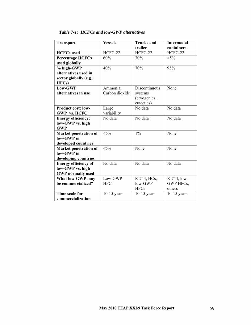
May 2010 TEAP XXI/9 Task Force Report 59
Table 7-1: HCFCs and low-GWP alternatives
Transport Vessels Trucks and trailer
Intermodal containers
HCFCs used HCFC-22 HCFC-22 HCFC-22 Percentage HCFCs used globally
60% 30% <5%
% high-GWP alternatives used in sector globally (e.g., HFCs)
40% 70% 95%
Low-GWP alternatives in use
Ammonia, Carbon dioxide
Discontinuous systems (cryogenics, eutectics)
None
Product cost: low-GWP vs. HCFC
Large variability
No data No data
Energy efficiency: low-GWP vs. high GWP
No data No data No data
Market penetration of low-GWP in developed countries
<5% 1% None
Market penetration of low-GWP in developing countries
<5% None None
Energy efficiency of low-GWP vs. high GWP normally used
No data No data No data
What low-GWP may be commercialized?
Low-GWP HFCs
R-744, HCs, low-GWP HFCs
R-744, low-GWP HFCs, others
Time scale for commercialization
10-15 years 10-15 years 10-15 years


May 2010 TEAP XXI/9 Task Force Report 61
8 Unitary Air Conditioning
8.1 Description of Product Category On a global basis, air-cooled air conditioners and heat pumps ranging in size from 2.0 kW to 420 kW comprise a vast majority of the air conditioning market below 400 tons. Nearly all air-cooled air conditioners and heat pumps manufactured prior to 2000 used HCFC-22 as their working fluid. Air-cooled air conditioners and heat pumps generally fall into four distinct categories, based primarily on capacity or application: small self-contained air conditioners (window-mounted and through-the-wall air conditioners); non-ducted or duct-free split residential and commercial air conditioners; ducted, split residential air conditioners; and ducted commercial split and packaged air conditioners (see 2006 RTOC Assessment report, UNEP Nairobi). Nearly all air-cooled air conditioners and heat pumps manufactured prior to 2000 used HCFC-22 as their working fluid. This corresponds to an HCFC bank of 1.2 million tonnes.
8.2 Current Situation 8.2.1 Primary HCFC-22 Replacements
In the developed countries, HFC refrigerants have been the dominant replacements for HCFC-22 in all categories of unitary air conditioners. The most widely used replacement is R-410A, a blend of two HFC refrigerants. The next most widely used replacement is R-407C, which is another HFC blend containing three HFC refrigerants. Systems using R-407C required less redesign than those using R-410A because R-407C exhibits performance and operational properties very similar to HCFC-22. However, over time the industry has converted more products to R-410A because of its size, cost and serviceability advantages. Both of these HFC blends have a GWP similar to HCFC-22. Hydrocarbons have been used in some low charge applications; including lower capacity portable room units and small split system air conditioners. Hydrocarbon refrigerants have GWPs nearly equal to zero. The international standard IEC 60335-2-40 describes the limits for use of flammable refrigerants for air conditioners and heat pumps. Building codes, product design and safety standards also control the usage of flammable refrigerants in most locations. Hydrocarbons are not likely to be broadly applied in equipment where the refrigerant charge exceeds 1 kg, because of the high cost required to address system safety. However, it should be noted that because of the relatively low liquid density of HCs, compared to most fluorinated refrigerants, approximately two to three times the cooling capacity is achievable with the same charge size.
May 2010 TEAP XXI/9 Task Force Report 62
8.2.2 Developed Country Status
The transition away from HCFC-22 is well underway or nearly complete in most developed countries. The phase-out of HCFC-22 in newly manufactured air conditioners in the EU occurred in 2004. The phase-out for newly manufactured products in North America and Japan was completed in 2009. While the EU, Japan and North America are the dominant producers and users of unitary air conditioning products among developed countries, other developed countries have either already phased out HCFC-22 or are currently phasing out following the timetable set by the Montreal Protocol.
8.2.3 Developing Country Status
Most developing countries are continuing to utilise HCFC-22 as the predominate refrigerant in unitary air conditioning applications. The two largest developing country markets are China and India. China is the largest producer of air conditioners worldwide. Air conditioner production in China supports a rapidly increasing local market and a growing export market. China currently has the capability of producing HCFC-22, R407C and R-410A air conditioners. The HCFC-22 air conditioners serve both the domestic and the remaining HCFC-22 export markets, while the R407C and R-410A products are being produced primarily for export to developed countries. With the recently approved adjustment to the Montreal Protocol, developing countries are expected to start to increase actions regarding the HCFC refrigerant replacement, including the elaboration of HCFC Phase-out Management Plans (HPMP) supported by the Multilateral Fund of the Montreal Protocol. The most likely near term replacements for use in developing countries are the HFC blends R-410A and R-407C for most applications and hydrocarbon refrigerants in smaller capacity applications.
8.3 Potential Low-GWP Options While R-410A and R-407C both have zero ozone depletion potential, both of these refrigerants have high global warming potentials. The air conditioning industry is currently exploring refrigerant alternatives, which have lower global warming potentials and/or better Life Cycle Climate Performance. However, the current candidates create new technical challenges of flammability, toxicity, peak load efficiency and economic feasibility. Some of the candidate low-GWP refrigerants are described in the following section. Additional candidates are expected to emerge as research into new low-GWP refrigerants continues.
8.3.1 HFC-32
HFC-32 is one of the primary constituents of both R-410A and R-407C. It is a pure HFC, which exhibits a higher capacity and efficiency than R-410A.

May 2010 TEAP XXI/9 Task Force Report 63
HFC-32 also has a moderate GWP approximately 32% of that of R-410A, which makes it a significantly lower GWP alternative to R-410A. HFC-32 has been given an “ASHRAE A2 flammability” rating with a relatively low flame speed. There would be limited technical challenges in replacing R-410A with HFC-32. Products using HFC-32 have not yet been commercialised but development is taking place, particularly in China.
8.3.2 HFC-1234yf and Blends with Other HFCs
HFC-1234yf has a very low-GWP and thermodynamic performance characteristics similar to HFC-134a. To date, the primary target application for this refrigerant has been the mobile air conditioning sector. HFC-1234yf is a lower pressure refrigerant than R-410A and HCFC-22. Therefore, air conditioning systems, which almost universally utilise HCFC-22 or R-410A today, would require significant redesign to utilise this refrigerant. The design changes (similar to the ones needed for application of HFC-134a) would include larger displacement compressors, larger heat exchangers, and modified refrigerant circuiting to match the performance (capacity and efficiency) of current HCFC and HFC systems. These changes are likely to significantly increase the system cost versus an existing HCFC-22 or R-410A system. Therefore, blends of HFC-1234yf with other HFC refrigerants are being investigated in order to develop low-GWP refrigerant options that more closely match the performance characteristics of R-407C or R-410A. HFC-1234yf is flammable, thus the flammability and resulting decomposition products would need to be mitigated in the design of the product. Environmental consequences of decomposition products to the global environment also need to be assessed.
8.3.3 Hydrocarbon Refrigerants
HC-290 (propane) is the hydrocarbon refrigerant most likely to be applied in air conditioning applications. It has performance characteristics very close to those of HCFC-22. The most significant issue involved in the application of propane is addressing its Class 3 (higher) flammability rating. However, HC-290 may be a very suitable refrigerant for systems that can be designed with a low charge. HC-290 has been applied in portable units containing less than 500 g of refrigerant and in mini-split system units with less than 1 kg of refrigerant. The safe application of hydrocarbon refrigerants in unitary systems containing more than 1 kg refrigerant is not likely to be cost effective. It should be noted that a system containing 1 kg of R290 is likely to provide a cooling capacity similar to a similarly designed R22 or R410A system containing 2-3 kg.
8.3.4 R-744 (Carbon Dioxide)
R-744, CO2, is the ideal refrigerant from the perspective of ODP and GWP. However, the low critical temperature of CO2 may result in efficiency losses when it is applied at the high indoor or outdoor air temperatures that may

May 2010 TEAP XXI/9 Task Force Report 64
occur for unitary air conditioning applications in certain climates. Two-stage compression, vapour injection, intra-cycle heat exchangers and the addition of ejectors or expanders are approaches that are under development to improve the efficiency of CO2 air conditioners. However these additions will add cost to the air conditioner and still may not fully address the performance shortfall. R-744 operated air conditioners are more likely to be applied in cool to moderately warm climates where the costs of addressing the efficiency will be more cost effective.
8.3.5 Product Energy Efficiency Improvement Technologies
As described in Section 3 of this report, there is a direct linkage between energy efficiency and the global warming impact of refrigeration technology options during use. Energy labelling and energy regulations are widely used to promote improved product energy efficiency. Experience in Europe, Japan, the United States and other countries have shown that product labelling and minimum efficiency regulations have been shown to transition markets to more efficient products; thus having a positive impact on the indirect emission of global warming gases.

May 2010 TEAP XXI/9 Task Force Report 65
Table 8-1: HCFCs and low-GWP alternatives
Unitary AC Small self contained AC
Non-ducted split AC
Ducted split residential AC
Ducted split commercial AC
% HCFCs available in subsector bank in the total
8% 41% 30% 21%
HCFCs used HCFC-22 HCFC-22 HCFC-22 HCFC-22 Percentage HCFCs used globally (bank/new equipm.)
90/66% 82/73% 81/44% 87/52%
% high-GWP alternatives used in sector globally (e.g., HFCs)
34% 27% 56% 48%
Low-GWP alternatives in use
HC-290 HC-290 none none
Product cost: low-GWP vs. HCFC
0-5% 5-10% N/A N/A
Energy efficiency: low-GWP vs. high GWP
0-5% improvement
0-5% improvement
N/A N/A
Market penetration of low-GWP in developed countries
<1% <0.3% N/A N/A
Market penetration of low-GWP in developing countries
? ? ? ?
Energy efficiency of low-GWP vs. high GWP normally used
comparable comparable N/A N/A
What low-GWP may be commercialized?
HFC-32, CO2, HFC-1234yf and HFC-1234yf blends
HFC-32, CO2, HFC-1234yf and HFC-1234yf blends
HFC-32, CO2, HFC-1234yf and HFC-1234yf blends
HFC-32, CO2, HFC-1234yf and HFC-1234yf blends
Time scale for commercialization
5-7 years 5-7 years 5-7 years 5-7 years


May 2010 TEAP XXI/9 Task Force Report 67
9 Chiller Air Conditioning
9.1 Introduction Comfort air conditioning in commercial buildings and building complexes is commonly provided by water chillers coupled with chilled water distribution and air handling and distribution systems. Chillers also are used for air conditioning and process cooling in industrial facilities. Vapour compression chillers are identified by the type of compressor they employ. They are classified as positive displacement compressors or centrifugal compressors. The positive displacement category includes reciprocating piston, screw, and scroll compressors. Chillers can be further divided according to their condenser heat exchanger type; water-cooled, air-cooled, and evaporatively-cooled. Water-cooled chillers generally employ cooling towers for heat rejection from the system. Air-cooled chillers are equipped with refrigerant-to-air condenser coils and fans to reject heat to the atmosphere. The selection of water-cooled, air-cooled, or evaporatively-cooled chillers for a particular application varies with regional climate conditions, water availability, owner preferences, and operational and investment cost evaluations.
9.2 Use of HCFCs In the developed countries, chillers with positive displacement compressors employed HCFC-22 until the Montreal Protocol phase-out date, 2010, approached for this refrigerant’s use in new equipment. (Europe phased out HCFC-22 in 2004.) . A portion of the market, particularly for chillers below 350 kW capacity, initially converted to R-407C refrigerant, which has physical and thermodynamic properties similar to those of HCFC-22. However, R-407C is a non-azeotropic mixture with an appreciable temperature glide (4-5 K), which negatively affects heat transfer. Chillers with R-407C require larger, more expensive heat exchangers to achieve competitive performance. The temperature glide makes R-407C unsuitable for use in larger chillers, which employ flooded evaporators. Reciprocating compressors, used for many years in HCFC-22 chillers, are being displaced in new products by screw and scroll compressors. For screw compressor chillers, the transition away from HCFC-22 (and R-407C) to HFC-134a was under way by 2005 or earlier in developed countries. Scroll compressor chillers began to employ HFC-134a or R-410A to deal with the phase-out of HCFC-22. The transition is just getting under way in Article 5 countries which have later phase-out dates for HCFC-22. HCFC-22 refrigerant is much less expensive than the common alternatives. Therefore, development spending for new chillers and compressors to use the alternative refrigerants is being postponed in these countries.

May 2010 TEAP XXI/9 Task Force Report 68
A number of “service fluids”, typically HFC blends, have been developed to replace HCFC-22 in existing equipment, notably smaller chillers. R-407C is one service fluid that can be used as an alternative in systems, which do not employ flooded evaporators. The conversion from HCFC-22 to R-407C requires a change in lubricants and other important steps that have been established. The manufacturer of the chiller should be consulted to assure that all factors, including material compatibility, have been taken into account. When R-407C or one of the service fluids is used in an existing system, there may be changes in cooling capacity and power consumption that are unacceptable to the end use customer.. Manufacturers’ warranties may not be supported after a conversion away from HCFC-22. Chillers with centrifugal compressors generally did not use HCFC-22. When CFC refrigerants were phased out, this class of chillers began to employ HFC-134a or HCFC-123 as refrigerants. Centrifugal chillers in developed countries and in Article 5 countries alike employ the same refrigerants, i.e., HFC-134a or HCFC-123. HCFC-123 is included under the Montreal Protocol HCFC phase-out schedule. There are no low-GWP replacements that have been commercialised yet to replace either refrigerant for centrifugal chillers. HFC-245fa was developed as a foaming agent and is available for use in centrifugal chillers. Its use has been limited. Centrifugal chillers must be designed specifically for HFC-245fa; it is not a drop-in replacement for either HCFC-123 or HFC-134a and it is not a low-GWP refrigerant.
9.3 Current or Future Use of Low-GWP Substances 9.3.1 R-717 (ammonia)
Chillers with R-717 as the refrigerant are available with screw compressors in the capacity range 100-7,000 kW. Chillers with reciprocating compressors are available in the capacity range 10-1,600 kW. R-717 chillers are manufactured in small quantities compared to HFC chillers of similar capacity. Applications in comfort cooling have been less common than in process cooling and the primary market for R-717 chillers has been Europe. Chillers employing ammonia as a refrigerant have been produced for many years. If the use of this refrigerant is to expand in the capacity range served by positive displacement compressors, several aspects must be addressed: Chiller costs are higher than for HFC chillers, partly because R-717
chillers are manufactured in smaller quantities and partly because they cannot use high performance copper heat exchanger tubing for heat transfer.
Safety concerns with R-717 in comfort cooling applications can increase installation costs. Present building codes in some countries heavily restrict applications. Building codes and regulations may need to be revised in those countries.

May 2010 TEAP XXI/9 Task Force Report 69
R-717 is not a suitable refrigerant for centrifugal compressor chillers because of its low molecular weight. This characteristic requires a large number of compressor stages to produce the pressure rise (“head”) required for the R-717 vapour compression cycle.
9.3.2 Hydrocarbons
Chillers employing hydrocarbons as a refrigerant have been available for over 10 years. HC-290 (propane is used in chillers in industrial applications. HC-290 and another hydrocarbon, HC-1270, are used in a limited number of small (<300 kW) air-cooled chiller installations in Europe. Some Article 5 countries such as Indonesia, Malaysia, and the Philippines are applying hydrocarbon chillers to large space cooling needs. Hydrocarbon refrigerants are available with properties similar to those of HFC-134a and HCFC-22, which allows them to be used in equipment of current design after appropriate adjustments for different material compatibility, lubricant, and safety aspects. However, safety codes restrict hydrocarbon use for large refrigerant charges in chillers due to problems associated with flammability. The safety issues are of concern particularly for indoor chiller installations (e.g., water cooled chillers in machinery rooms). In regions where companies, governments, and the public support hydrocarbon solutions, these safety concerns have been largely overcome by engineering, technician training, and changes in regulations. However, in countries such as the U.S.A., regulations, building codes, and legal environments continue to pose difficulties for hydrocarbon use in commercial chillers.
9.3.3 R-744 (carbon dioxide)
Several companies have started the production of R-744 chillers. R-744 has poor energy efficiency. Even with a number of cycle enhancements (e.g., recovery of expansion energy, economiser features) the energy efficiency is inferior to that of systems employing HFCs, R-717, or hydrocarbons. Chillers employing carbon dioxide are not known to meet present chiller energy efficiency standards. The indirect global warming effect from the higher energy consumption of R-744 chillers makes them a poor choice from a Life Cycle Climate Performance (LCCP) perspective. In cooler climates such as in northern Europe, R-744 chillers are accepted as alternatives to HFC chillers. Where heat recovery to generate hot water at temperatures of 60o C or higher can be employed in a total energy strategy for a building, R-744 chillers offer the advantage of being able to use waste heat to raise water to higher temperatures with higher efficiency than other refrigerants. Chilled water can be used to sub-cool the refrigerant before expansion. For this application, R-744 heat recovery chillers provide good efficiency.

May 2010 TEAP XXI/9 Task Force Report 70
9.3.4 R-718 (water vapour)
The low pressures, high compression ratios, and high volumetric flow rates required in water vapour compression systems require compressor designs that are uncommon in the chiller field though several companies and research projects have attempted their commercialization. Applications for water as a refrigerant can chill water or produce an ice slurry by direct evaporation from a pool of water. R-718 systems carry a significant cost premium above conventional systems. The higher costs are inherent and are associated with the large physical size of water vapour chillers and the complexity of the compressor technology. Several systems have been demonstrated in Europe, Israel and South Africa
9.3.5 HFC-1234yf
Chemical manufacturers are offering unsaturated hydrofluorochemicals to replace HFC-134a in mobile air conditioning. If adopted in the mobile sector, exploration of use in chillers is expected. If not, then commercialization for the HVAC industry for use in chillers may not occur. HFC-1234yf and a proprietary blend composed of HFC-1234zf (E) with two other HFCs are among those most prominently discussed. These refrigerants have properties similar to HFC-134a with much lower GWP. They have potential application in the range of screw and, at least for HFC-1234yf, centrifugal chillers manufactured today. Initial studies based on thermodynamic properties suggest that the performance of HFC-1234yf refrigerant is not as good as for HFC-134a. Design changes and costs to meet minimum efficiency standards are not known. Safety concerns need to be evaluated. HFC-1234yf has an A2 rating according to ISO 817 and ASHRAE Standard 34. This rating would restrict its use under present safety codes and standards in countries such as the U.S. However, a new safety classification is being suggested to recognize that this refrigerant is difficult to ignite and does not readily sustain a flame (so called ‘slightly flammable’ refrigerant). At this time it is not possible to know whether HFC-1234yf will find significant usage as a refrigerant in chillers.
9.4 Markets R-717 (ammonia): The current market for R-717 chillers is of the order of a few hundred units annually compared to tens of thousands of chillers employing HCFC-22 and HFCs. The market for R-717 chillers is likely to grow in the future in regions where concerns about use of high-GWP refrigerants are strong. However, safety concerns in comfort cooling applications will increase installation costs and decrease flexibility of installation arrangements. R-717 is better suited to water-cooled chillers because of higher costs and reduced performance of air-cooled R-717 condenser coils. It is unlikely that R-717 chillers will displace more than a few

May 2010 TEAP XXI/9 Task Force Report 71
percent of HFC chillers so long as current HFC refrigerants can be used or new low-GWP HFC refrigerants are found suitable for chiller applications. Hydrocarbons: The current market for chillers employing hydrocarbon refrigerants is larger than for R-717 chillers but still very small compared to the market for HCFC-22 and HFC chillers. Hydrocarbon chillers for comfort cooling are limited in practical terms to units <300 kW capacity by safety restrictions on the quantity of refrigerant contained in the chiller system. The use of hydrocarbon refrigerants in small chillers is likely to grow in the future where codes and regulations allow. R-744 (carbon dioxide): This low-GWP refrigerant is unsatisfactory for use in chillers for comfort cooling because of poor energy efficiency. Where heat recovery to generate hot water at temperatures of 60o C or higher is part of the total energy strategy for an application, R-744 may find increasing use. It is not clear whether R-744 systems will attain capacities above 100 kW in the future. The high operating pressures make development of special compressors and other components necessary. The market size for larger R-744 systems with heat recovery may not support the development cost of the components. R-718 (water vapour): For reasons described in Section 10.2, R-718 chillers are not likely to attain a significant market share. They may be used in special applications only. HFC-1234yf and other unsaturated fluorocarbons: As stated above, at this time it is not possible to know whether HFC-1234yf and other unsaturated fluorocarbons will find significant usage as a refrigerant in chillers.
9.6 Appendix: Some Standards for Ensuring Safe Application of Refrigerants
ANSI/ASHRAE Standard 15-2007, “Safety Standard for Refrigeration Systems”, American Society of Heating, Refrigeration, and Air-Conditioning Engineers (ASHRAE) Atlanta, GA, USA, 2007 ASHRAE Standard 34-2007, “Designation and Safety Classification of Refrigerants (ANSI Approved) American Society of Heating, Refrigeration, and Air-Conditioning Engineers (ASHRAE) Atlanta, GA, USA, 2007 EN378: 2008, Institute of Refrigeration Safety Code of Practice for A2/A3 Refrigerants, 2008

May 2010 TEAP XXI/9 Task Force Report 72
9.7 Table 9-1: Table of HCFCs and Low-GWP Alternatives for Chillers
Estimates in this table are for new equipment built after 1/1/2010
Chiller Type Small recip. and scroll 10-1,600 kW
Larger recip. and screw 100-7,000 kW
Centrifugal 210-10,500 kW
HCFCs used HCFC-22 HCFC-22 HCFC-123 % HCFCs used in sector globally
Near 100% in Article 5 countries, 0% in non-Art. 5 countries
Near 100% in Article 5 countries, 0% in non-Art. 5 countries
About 30%
% high-GWP alternatives used in sector globally (e.g., HFCs)
Near 100% in non-Article 5 countries
>95% in non-Article 5 countries
About 70%
Low-GWP alternatives in use
Hydrocarbons in systems <300 kW
R-717 (ammonia) None
Product cost: low-GWP vs. HCFC
No reliable numbers Not available*
Energy efficiency: low-GWP vs. high GWP
Similar to 5% higher Similar
Market penetration of low-GWP in developed countries
< 2% <2%
Market penetration of low-GWP in developing countries
<2% <1%
Energy efficiency of low-GWP vs. high GWP normally used
HC vs. HFC-410a Similar to 5% higher
R-717 vs. HFC-134a Can be similar
What low-GWP may be commercialized?
HFC-1234yf HFC-1234yf HFC-1234yf
Time scale for commercialization
5 years 5 years 5 years
* The low-GWP equipment is produced in small quantities compared to HCFC equipment. Costs are >20% higher not including costs to meet safety codes which vary from country to country

May 2010 TEAP XXI/9 Task Force Report 73
10 Vehicle Air Conditioning 10.1 Introduction
Vehicles (cars, trucks, and buses) built before the mid-1990’s used CFC-12 as the refrigerant. Since then, in response to the Montreal Protocol, new vehicles with air conditioning (abbreviation A/C, in this report the abbreviation MAC for Mobile Air Conditioning is used) have been equipped with systems using HFC-134a, a zero ODP refrigerant. As of the year 2000, all new vehicles are sold with air conditioning systems using HFC-134a and the transition from CFC-12 is complete.
10.2 Options for Future Mobile Air Conditioning Systems For sake of clarity, in this paper mobile air conditioning systems are those used in passenger cars, light duty trucks, buses and rail vehicles. This paper is an update of the publication dated May 2009.
10.2.1 Bus and Rail Air Conditioning
At present, no regulation is foreseeable in the EU on fluorinated greenhouse gases used as refrigerants for MAC systems in buses and rail cars (note: a review of the MAC directive in 2011 will consider whether other classes of vehicles need to be considered). However, because the car industry will phase out HFC-134a under the EU F-gas directive between 2011 and 2017, it is likely that this will influence the HFC-134a phase out also in buses and railcars. Worldwide approximate 50% of all buses and trains are still equipped with HCFC-22 systems. The rest is equipped mostly with HFC-134a or R-407C systems. Owing to the high quantities of refrigerant charges (10 kg and more) flammability concerns make the use of flammable refrigerants (like propane, HFC-152a and HFC-1234yf) as low-GWP alternatives unlikely. One German company has announced that they have already R-744 systems for buses and trains ready to sell. R-744 systems have similar energy efficiency as the existing systems. Generally speaking, the time scale for an anticipated commercialization for R-744 systems for buses is longer than 2 or 3 years with an estimated cost increase of 20 to 50 %. Trains use only hermetic or half hermetic systems where all components are already commercially available. Hence, for trains the time scale for an anticipated commercialization is in the order of 1 or 2 years with an estimated cost increase of 20 to 50 %48 as well.
10.2.2 Passenger Car and Light Truck Air Conditioning
This section covers the various refrigerants considered for use in passenger cars and light trucks that use refrigerant systems similar to passenger cars.
48 Numbers for cost and anticipated commercialization time are authors' best estimates because no formal and sound references are available.

May 2010 TEAP XXI/9 Task Force Report 74
10.2.2.1 Improved HFC-134a Systems
As the list of regulations grows limiting the use of HFC-134a, this may not be an option for mobile air conditioning systems in the near future. This is definitely the case for the EU. Other countries will probably follow or provide incentives to reduce the usage of HFC-134a in these vehicles.. However, HFC-134a-systems with improved leakage rates and energy efficiency might still be an intermediate option for some countries.
10.2.2.2 Carbon Dioxide (R-744) Systems
The refrigerating equipment safety standard (ASHRAE 34) classifies R-744 as an A1 refrigerant, a low toxicity and non-flammable refrigerant. The SAE CRP1234 performed a risk assessment of R-744 systems as compared to HFC-1234yf and determined that the risks are low and similar, but HFC-1234yf has demonstrated even slightly less risk than R-744. SAE standards have been developed to cover service best practices and refrigerant purity of R-744. At present, the US EPA is studying the potential use of R-744 as a refrigerant under the US Clean Air Act’s Significant New Alternatives Policy (SNAP) Program. A ruling is expected soon.
R-744 has been shown to be comparable to HFC-134a with respect to cooling performance and fuel use in MAC systems and qualifies for use in the EU under the current impending regulation.
Currently, still technical (reliability, leakage, NVH especially system noise) and commercial (additional costs) hurdles exist that will require resolution prior to the commercial implementation of R-744 as refrigerant for car air conditioning.
Following investigation of numerous alternatives to the currently used HFC-134a, vehicle manufacturers in the German Association of the Automotive Industry (VDA) have announced intentions to use the natural refrigerant R-744 in vehicle air-conditioning systems in the future. However, at present, neither German OEMs nor their suppliers are working on this solution. So, it will not be possible to meet the 2011 European requirement if this refrigerant has to be used. Generally speaking, the time scale for an anticipated commercialization for R-744 systems is longer than 5 years with an estimated cost increase of 50 to 75%49.
10.2.2.3 HFC-152a Systems
HFC-152a is classified as an A2 refrigerant, lower toxicity and lower flammability (ASHRAE 34). Because of its flammability, it would require additional safety systems.
49 Numbers for cost and anticipated commercialization time are authors' best estimates because no formal and sound references are available.

May 2010 TEAP XXI/9 Task Force Report 75
The US EPA has studied the potential use of HFC-152a as a refrigerant under the US Clean Air Act’s Significant New Alternatives Policy (SNAP) Program and has SNAP-listed HFC-152a as refrigerant under the following conditions: Engineering strategies and/or devices shall be incorporated into the system such that foreseeable leaks into the passenger compartment do not result in HFC-152a concentrations of 3.7% v/v or above in any part of the free space inside the passenger compartment for more than 15 seconds when the car ignition is on.
HFC-152a has been shown to be comparable to HFC-134a with respect to cooling performance and fuel use in MAC systems and qualifies for use in the EU under the aforementioned regulation.
At present, no car manufacturer has selected HFC-152a as the refrigerant for A/C serial production due to technical and commercial issues related to the secondary loop system. Most development activity has been focused on using this refrigerant in a secondary loop system as a means of assuring safe use. This system utilises glycol and water as the direct coolant in the passenger compartment with this coolant being cooled under-hood by the refrigerant. Prototype vehicles have been demonstrated by several of the OEMs. Generally speaking, the time scale for an anticipated commercialization for HFC-152a systems is longer than 3 years with an estimated cost increase of 20 to 30%50.
10.2.2.4 Blend Alternatives
In early 2006, several chemical companies announced new non-flammable refrigerant blends to replace HFC-134a in Europe. One was an azeotropic blend of CF3I and HFC-1234yf (2,3,3,3-tetrafluoroprop-1-ene). Two other formulations were zeotropic blends of HFC-1234yf, HFC-1225ze, HFC-1225ye, HFC-32, and minor concentrations of HFC-134a. However, the refrigerant blends were withdrawn by chemical companies in the fourth quarter 2007 after discovery of chronic toxicological effects.
Additional low-GWP blend alternatives are still under development for mobile air conditioning and for other stationary applications.
One chemical company has announced their next generation refrigerant. It is a zeotropic blend, containing the unsaturated HFC-1243zf, HFC-32, and HFC134a for which the final blend formulation has not been publicly disclosed, but for which the production routes of the individual components should be similar to that of HFC-134a. The GWP is a little less than 150 and the flammability of this blend is very similar to that of HFC-1234yf (LFL = 5 - 6 Vol.% and UFL = 13-16 Vol.%). Owing to an approximate 8 percent lower mass flow rate the energy efficiency seems to be better than that of HFC-134a. In addition to that, the toxicity is also expected to be low. The
50 Numbers for cost and anticipated commercialization time are authors' best estimates because no formal and sound references are available.

May 2010 TEAP XXI/9 Task Force Report 76
earliest time to start high volume mass production has been reported to be 2013.
10.2.2.5 HFC-1234yf Systems
In the fourth quarter of 2007, the flammable substance HFC-1234yf, which was one component of the above-mentioned blends was proposed as a global mobile A/C refrigerant. At the January 2010 ASHRAE meeting, this refrigerant was also given an A2 rating. ASHRAE has also proposed to add the classification of A2L [similar to ISO817] and owing to its low flame velocity, this refrigerant will be reclassified A2L by ASHRAE if this is approved.
With a GWP of 4, the low toxicity substance HFC-1234yf qualifies for use in the EU under the aforementioned EC F-Gas Directive. HFC-1234yf has a lower flammability (also described as “being mildly flammable”) as measured by standard methodology and a classification as an A2L refrigerant according to ISO 817 is likely. HFC-1234yf is a new chemical currently undergoing EPA Pre-manufacture Notice (PMN) and EPA SNAP review. It has been registered for low volume applications by REACH review in the EU. The high volume REACH application was submitted in February 2009. As with HFC-152a, use of any flammable substitute is subject to US state safety conditions on flammable refrigerants. The US EPA reported that barriers had been removed in all states. The German Federal Institute for Materials Research and Testing (BAM) has found that the flammability region of HFC-1234yf increases significantly in the presence of small concentrations of hydrocarbons (less than 1%, which can occur in the engine compartment due to gasoline or cracked oil). However, vehicle manufacturers have explained that these tests were not done in a way that is typical of the under-hood environment as they were done in a sealed chamber. [This statement can be found in the comments to the EPA SNAP proposal]. The BAM report concludes that in the case of HFC-1234yf leakages the probability to produce explosive atmospheres in the presence of hydrocarbons is larger than that of HFC-134a leakages, but this explosive atmosphere is less than that which exists with pure hydrocarbons.
HFC-1234yf has been shown to be comparable to HFC-134a with respect to cooling performance and fuel use in MAC systems and qualifies for use in the EU under the aforementioned regulation.
HFC-1234yf requires a different chemical process route in comparison to that of HFC-134a and a simple conversion of existing assets is not possible. Two North American chemical companies have announced that they will supply market demand after regulatory approval, but have not announced a timetable for the installation of a new HFC-1234yf production plant. These companies now share a patent on the use of this refrigerant in MAC systems and other manufacturers will have to purchase a license to manufacture.

May 2010 TEAP XXI/9 Task Force Report 77
Many global car OEMs have expressed their interest in HFC-1234yf. In October 2008, after thorough examinations by German automotive companies, the VDA announced that most of them had completed their assessments and found that the alternative refrigerant HFC-1234yf is not an option. In March of 2009, all German OEMs joined the effort to evaluate HFC-1234yf with other global manufacturers. In November 2009, all major global car OEMs (including the German OEMs) have concluded in the SAE CRP1234 Report that HFC-1234yf can be used as global replacement refrigerant in future mobile air conditioning systems and can be safely accommodated through established industry standards and practices for vehicle design, engineering, manufacturing, and service. However, no car OEM has yet announced a commitment to use HFC-1234yf as refrigerant for production in a new MAC system. Generally speaking, the time scale for an anticipated commercialisation for HFC-1234yf systems is longer than 2 or 3 years with an estimated cost increase of 20 to 30%51.
Table 10-1: HCFCs and low-GWP alternatives (in busses and trains) Buses Trains HCFCs used HCFC-22 HCFC-22 Percentage HCFCs used globally
50% 50%
% high-GWP alternatives used in sector globally (e.g., HFCs)
50% 50%
Low-GWP alternatives in use
none None
Product cost: low-GWP vs. HCFC
CO2: 1.2-1.5 CO2: 1.2-1.5
Energy efficiency: low-GWP vs. high GWP
Alternatives are comparable to HFCs
Alternatives are comparable to HFCs
Market penetration of low-GWP in developed countries
Market penetration of low-GWP in developing countries
Energy efficiency of low-GWP vs. high GWP normally used
Alternatives are comparable to HFCs
Alternatives are comparable to HFCs
What low-GWP may be commercialized?
CO2 CO2
Time scale for commercialization
> 2-3 years > 1-2 years
Numbers estimated for costs and anticipated commercialisation time are author’s best estimates because no formal and sound references are available
51 Numbers for cost and anticipated commercialisation time are authors' best estimates because no formal and sound references are available.
May 2010 TEAP XXI/9 Task Force Report 78
The following literature sources have been specifically consulted in this chapter on vehicle air conditioning: 1234yf OEM group: Update 1234 as a replacement for R134a. MAC Summit, Scottsdale 2008. Andersen, Stephen O., Kristen N. Taddonio, US EPA Climate Protection Partnerships Division, New Realities In MAC Refrigerant Choice, Stephen, MACs Convention, 06 February 2009, http://www.epa.gov/cppd/mac/2010-mac-annualmtg-0120.htm. Arkema Press Release, Arkema launches an industrial production project in Europe of a low-GWP* fluorinated gas for automotive air-conditioning, July, 2008. ARMINES Reference 70890, Arnaud Tremoulet, Youssef Riachi, David Sousa, Lionel Palandre, Denis Clodic, Evaluation of the Potential Impact of Emissions of HFC-134a from Nonprofessional Servicing of Motor Vehicle Air Conditioning Systems, CARB Agreement No. 06-341, July, 2008. ASHRAE Position Document on Natural Refrigerants. American Society of Heating, Refrigerating and Air-Conditioning Engineers, Atlanta, 28 January, 2009 (http://www.ashrae.org/aboutus/page/335). Baker, James, Mahmoud Ghodbane, John Rugh, William Hill, Alternative Refrigerant Demonstration Vehicles, SAE ARSS 2007 BAM Test Report II-2318/2009, Determination of the explosion region of ethane-HFO1234yf-air mixtures, BAM Federal Institute for Materials Research and Testing, 12200 Berlin, November 17, 2009 [available on EPA SNAP website.] Baker, James A., Revising J-2727, 2006 ARSS. Bang, Scott, Comparative Life Cycle Assessment on Alternative Refrigerants, SAE ARSS 2008 Bang, Scott, Evaluation Result of HFO-1234yf as an Alternative Refrigerant for Automotive Air Conditioning, VDA Winter Meeting, 2008 Clodic, D., G. El Khoury, Energy consumption and environmental footprint of MAC system of full hybrid vehicles, VDA Winter Meeting, 2009 Bauer, I., Transport Refrigeration – Current Technologies, Market andTrends. Master Thesis Karlsruhe University of Applied Sciences, May 2006

May 2010 TEAP XXI/9 Task Force Report 79
Comments to the HFC-1234yf SNAP proposal: Risk Assessment for Alternative Refrigerants HFO-1234yf and R-744 (CO2) Phase III report, Dec. 18, 2009 [http://www.regulations.gov/search/Regs/home.html#documentDetail?R=0900006480a6df2d], Dr. Thomas Lewandowski, Gradient Corporation [Additional Comments on the EPA SNAP proposal can be found at the following link at www.regulations.gov: http://www.regulations.gov/search/Regs/home.html#searchResults?No=70&Ne=11+8+8053+8098+8074+8066+8084+1&Ntt=EPA-HQ-OAR-2008-0664&Ntk=All&Ntx=mode+matchall&N=0 ] Cox, N. , V. Mazur, D. Colbourne, New High Pressure Low- GWP Azeotroic And Near-Azeotropic Refrigerant Blends, 12th International Refrigeration and Air Conditioning Conference, Purdue University, July, 2008. Directive 2006/40/EC of the European Parliament and of the Council of 17 May 2006 relating to emissions from air-conditioning systems in motor vehicles and amending Council Directive 70/156/EEC. Official Journal of the European Union L161/12 (2006). DuPont and Honeywell: Guidelines for Use and Handling of HFC-1234yf. 2008. Elbel, Stefan, Pega Hrnjak, Experimental Validation of a CO2 Prototype Ejector with Integrated High-Side Pressure Control, VDA Winter Meeting, 2007 Eustice, Harry, Assessment of Alternate Refrigerants for EU Regulations, SAE ARSS 2008 Graaf, Marc, The Influence of the Accumulator and Internal Heat Exchanger Design as separate and combined Components on the System Behavior of a R744 A/C System, VDA Winter Meeting, 2005 Graz, Martin, Investigation on Additional Fuel Consumption for a R134a and R744 AC – System in a VW Touran, VDA Winter Meeting, 2009 Hammer, Hans, Results of Audi A5 Evaluation with Alternate Refrigerants, SAE ARSS 2008 Heckt, Roman, Cost efficient R744 AC System for Compact Vehicles, VDA Winter Meeting, 2005 Hekkenberg, M., Anton J.M. Schoot Uiterkamp, University of Groningen, Center for Energy and Environmental Studies IVEM, Nijenborgh 4, 9747 AG Groningen, The Netherlands, Exploring policy strategies for mitigating HFC

May 2010 TEAP XXI/9 Task Force Report 80
emissions from refrigeration and air conditioning, international journal of greenhouse gas control 1 (2007) 2 9 8 – 3 0 8 Hrnjak, Pega, Technological and theoretical opportunities for further improvement of efficiency and performance of the refrigerant candidates achievements and potentials of efficiency increase, VDA Winter Meeting, 2007 Ikegami, Tohru, Masahiro Iguchi, Kenta Aoki, Kenji Iijima, New Refrigerants Evaluation Results, SAE ARSS 2008 IPCC/TEAP Special Report on Safeguarding the Ozone Layer and the Global Climate System: Issues Related to Hydrofluorcarbons and Perfluorcarbons. 2005 Prepared by Working Group I and III of the Intergovernmental Panel on Climate Change, and the Technology and Economic Assessment Panel. Cambridge University Press, Cambridge, United Kingdom and New York, NY, USA, 488 pp. Jung, Dongsoo, , Yoonsik Ham, Performance of R429A and R430A to replace HFC134a in mobile air-conditioners, Phoenix 2007,ARSS. Koehler, J., Strupp, N. C., Kling, M. E., and Lemke, N. C.: Refrigerant comparison for different climatic regions. The International Symposium on New Refrigerants and Environmental Technology, Kobe, 20-21 November 2008. König, Holger, Rüdiger Roth, Part 1: Developmentof a supercriticalCO2-test rigPart 2: CO2-State Of The Art in Industrial Refrigeration, VDA Winter Meeting, 2005 Low, R. E.: Update on INEOS Fluor Refrigerant Development Program. VDA Winter Meeting, Saalfelden, 11-12 February 2009. Low, R.E.: Minderung des Einflusses von Klimaanlagen auf die Umwelt – Perspektiven von INEOS Fluor, DKV Annual German Refrigeration and Air Conditioning Conference, Berlin, November 18-20, 2009 Malvicino, C., The 4 Fiat Pandas Experiment and other considerations on refrigerants, SAE ARSS 2008 Malvicino, Carloandrea, B-Cool, Low Cost and High Efficiency CO2 Mobile Air Conditioning system for lower segment cars, VDA Winter Meeting, 2005 Man-Hoe Kim, J.-S. Shin, W.-G. Park, S. Y. Lee, The Test Results of Refrigerant R152a in an Automotive Air-Conditioning System, Phoenix ARSS 2008.

May 2010 TEAP XXI/9 Task Force Report 81
Meininghaus, Roman, Dietmar Fischer, MAC Energy Efficiency, 1. A Broader Perspective, 2. Aspects of Virtual Testing, VDA Winter Meeting, 2009 Meyer, John, R1234yf System Enhancements and Comparison to R134a, SAE ARSS 2008 Montforte, R., B. Rose, J-M. L’Huillier, Fiat, Renault and PSA outlook on the selection of a Global Alternative Refrigerant, SAE ARSS 2007 Montforte, R., B. Rose, J-M. L’Huillier, Updated situation about alternative refrigerant evaluation, SAE ARSS 2008 Montforte R., MAC System Fuel Consumption in various climate conditions, SAE ARSS 2007 Monforte, Roberto, , Carloandrea Malvicino, , Tim Craig, , Secondary Loop System for small cars, 2nd European Workshop on MACS & Auxiliaries, Mirafiori Motor Village, Torino - 29/11/07. Monforte, Roberto, Alternative Refrigerants, Assessment of the Environmental Impact of MACS and Investigation of its reduction drivers, VDA Winter Meeting, 2008 Morgenstern, Stefan, R744 MAC Status and System Standardization, VDA Winter Meeting, 2008 Papasavva, Stella, William R. Hill, Assessing the Life Cycle Greenhouse Gas Emissions of HFC-134a, HFC-1234yf and R-744 using GREEN-MAC-LCCP©, VDA Winter Meeting, 2009 Papasavva ,Stella, William R. Hill, GREEN-MAC-LCCP© Global Refrigerants Energy & ENvironmental – Mobile Air Conditioning - Life Cycle Climate Performance, SAE ARSS 2007 Porrett, Ken, Eric Scarlett, 1234yf System Evaluation, SAE ARSS 2008 Riegel, Harald, Efficiency of Mobile Air Conditioning, SAE ARSS 2008 Riegel, Harald, Efficiency of Refrigerant Circuits – Comparison of Alternative Refrigerants, SAE ARSS 2007 Riegel, Harald, Status of R744 Development, VDA Winter Meeting, 2007

May 2010 TEAP XXI/9 Task Force Report 82
Rinne, Frank, HFO-1234yf Technology Update-Part I, VDA Winter Meeting, 2009 SAE, http://www.sae.org/mags/sve/6323, 14 May 2009 (information regarding composition AC-4 blend, containing HFC-1243zf) SAE, http://www.sae.org/standardsdev/tsb/cooperative/crp1234-3.pdf, 10 November 2009 (information regarding CRP1234 Report) Schwarz, W. and Rhiemeier, J. M.: The analysis of the emissions of fluorinated greenhouse gases from refrigeration and air conditioning equipment used in the transport sector other than road transport and options for reducing these emissions, Maritime, Rail, and Aircraft Sector. Final Report prepared for the European Commission (DG Environment), (07010401/2006/445124/MAR/C4) 2 November 2007. Schwarz, W.: Establishment of Leakage Rates of Mobile Air Conditioners in Heavy Duty Vehicle, Part 2 Buses and Coaches. Final Report prepared for the European Commission (DG Environment), (ENV.C.1/SER/2005/0091r) 31 January 2007. Sciance, Fred : Improved Mobile Air Conditioning Cooperative Research Program, Presented at the SAE 2006 Automotive Alternate Refrigerants Systems Symposium, Scottsdale, AZ, June 2006. SAE International, Warrendale, PA 15096-0001. Spatz, Mark, Barbara Minor, HFO-1234yf Low-GWP Refrigerant: A Global Sustainable Solution for Mobile Air Conditioning, SAE ARSS 2008 Spatz, Mark, HFO-1234yf Technology Update-Part 2, VDA Winter Meeting, 2009 Spatz, Mark, Barbara Minor, HFO-1234yf A Low-GWP Refrigerant For MAC, Honeywell / DuPont Joint Collaboration, VDA Winter Meeting, 2008 Thundiyil, K.: Refrigerant choice under SNAP. VDA Winter Meeting, Saalfelden, 11-12 February 2009. TohruIkegami, Masahiro Iguchi, Kenta Aoki, Kenji Iijima, New RefrigerantsEvaluation Results, VDA Winter Meeting, 2008 U.S. Environmental Protection Agency (2004). Risk Analysis for Alternative Refrigerant in Motor Vehicle Air Conditioning. U.S. EPA: Washington D.C.

May 2010 TEAP XXI/9 Task Force Report 83
U.S. Environmental Protection Agency (2009). Report of the EPA Working Group on R744 (Working Document). Kristen Taddonio, Lead Author. U.S. EPA: Washington D.C. UNEP (United Nations Environment Program): UNEP Refrigeration, Air Conditioning an Heat Pumps Technical Options Committee (RTOC), 2006 Report of the Refrigeration, Air Conditioning and Heat Pumps Technical Committee, 2006 RTOC Assessment Report, United Nations Environment Program, Nairobi, January 2007, 235 pp. VDA announcement, Frankfurt am Main, 20 October 2008, http://www.vda.de/en/meldungen/news/20081020.html. VDA announcement, Frankfurt am Main, 6 September 2007, http://www.vda.de/en/meldungen/archiv/2007/09/06/1690/. Wertenbach, Juergen, Overview of Alternate Refrigerants, SAE ARSS 2007 Wieschollek, Florian, Dr. Roman Heckt, Improved Efficiency for Small Cars with R-744, VDA Winter Meeting, 2007 Wiesmueller, Joachim J., Status of R744 Deployment and Way Forward, VDA Winter Meeting, 2006 Wolf, Frank, R744 the Global Solution Advantages & Possibilities, VDA Winter Meeting, 2007 www.pca.state.mn.us/climatechange/mobileair.html#leakdata.

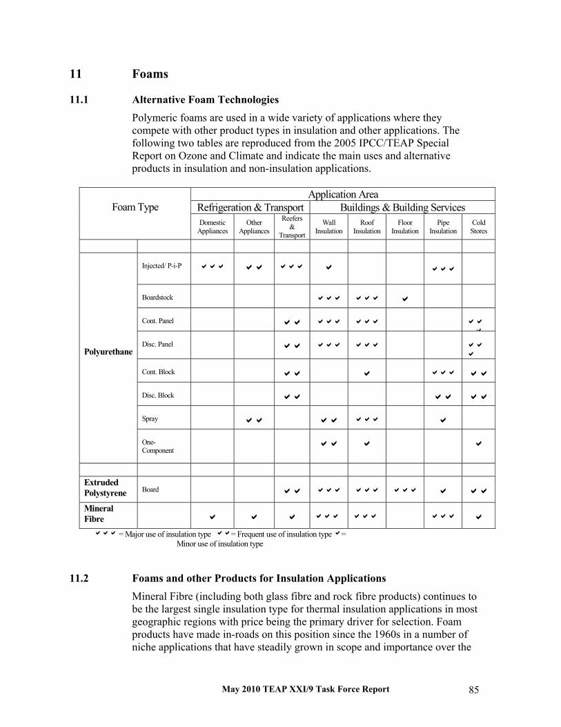
May 2010 TEAP XXI/9 Task Force Report 85
11 Foams
11.1 Alternative Foam Technologies Polymeric foams are used in a wide variety of applications where they compete with other product types in insulation and other applications. The following two tables are reproduced from the 2005 IPCC/TEAP Special Report on Ozone and Climate and indicate the main uses and alternative products in insulation and non-insulation applications.
11.2 Foams and other Products for Insulation Applications
Mineral Fibre (including both glass fibre and rock fibre products) continues to be the largest single insulation type for thermal insulation applications in most geographic regions with price being the primary driver for selection. Foam products have made in-roads on this position since the 1960s in a number of niche applications that have steadily grown in scope and importance over the
Application AreaRefrigeration & Transport Buildings & Building ServicesFoam TypeDomestic
AppliancesOther
Appliances
Reefers&
Transport
WallInsulation
RoofInsulation
FloorInsulation
PipeInsulation
ColdStores
Injected/ P-i-P aaa aa aaa a aaa
Boardstock aaa aaa a
Cont. Panel aa aaa aaa aaa
Disc. Panel aa aaa aaa aaa
Cont. Block aa a aaa aa
Disc. Block aa aa aa
Spray aa aa aaa a
Polyurethane
One-Component aa a a
ExtrudedPolystyrene Board aa aaa aaa aaa a aa
MineralFibre a a a aaa aaa aaa a
aaa = Major use of insulation type aa= Frequent use of insulation typea=Minor use of insulation type

May 2010 TEAP XXI/9 Task Force Report 86
intervening period. As insulation standards become more stringent, for example in Northern Europe, low thermal conductivity foams gain market share versus higher thermal conductivity fibre insulation as the thickness required for the latter would be too high to be accommodated in walls and roofs. The insulation long term performance remains a key component of the Life Cycle Climate Performance (LCCP) of buildings which is becoming an increasingly important parameter as global climate policy focuses more on the contribution of energy efficiency in general and building energy efficiency in particular. Foams typically hold a market share of 30-40% in most regions despite their higher unit cost and, for a number of applications, they remain the only practical option. Therefore, the search for alternative blowing agents to support the sector has continued through CFC phase-out and now HCFC phase-out. The following sections document the alternatives in each case.
11.3 Polyurethane (PU) Foams The main PU sectors using HFCs and HCFCs are insulating foams, integral skin foams and microcellular foams (shoe soles). In the last two sectors the usage is much less than in the insulating market because of the smaller overall market and the higher foam density. Historically, the use of HFCs and HCFCs was not necessary for the replacement of CFCs in the main flexible foam sectors such as slabstock, used for upholstered furniture and mattresses, and moulded foam used for car seats, although there are minor exceptions in specialty products. The table on the following page describes the blowing agents currently used. In insulating foams, additionally to the physical expansion of the reactive mixture, the blowing agent plays a critical role in the insulating performance. It should remain in the closed cells of the foam and have a low gaseous thermal conductivity. It must also be safe to use (human toxicity and flammability) and economic in terms of the required processing equipment. These considerations explain why HCFC-141b was one of the preferred options to replace CFC-11 in the developing countries and why HFC-245fa and HFC-365mfc (normally blended with HFC-227ea to reduce flammability, 7 or 13 % by weight) are widely used in the developed countries. In integral skin foams and shoe soles, the blowing agent should contribute to the skin formation governed by gas condensation under the high injection pressures and relatively low mould temperatures. The poor skin formation provided by water blown systems has made HCFC-141b the preferred option in developing countries and has promoted the use of HFCs, mainly HFC-134a, in developed countries.

May 2010 TEAP XXI/9 Task Force Report 87
11.4 Established HCFC Alternatives
Hydrocarbons Since the early 1990s hydrocarbons have been the preferred route to replace HCFCs and HFCs. The technology has evolved from the initial 100 % n-pentane or cyclo-pentane to blends with other hydrocarbons, particularly isopentane and isobutane. These blends provide a greater gas pressure in the foam cell and allow the reduction of foam density. Today hydrocarbons have become the most widely applied technology in the world for PU foams. A notable exception is spray foam, where hydrocarbons are not an option for safety reasons. Although suitable for large manufacturing facilities, this technology is not economic to apply in small and medium enterprises because of the high equipment conversion cost to ensure a safe use with HCs. A rough estimate of the capital cost for one dispenser unit, which involves storage tank, pre-blending station, sensors and venting, is in the range of US $400,000 to 700,000. Despite the higher gaseous thermal conductivities of the hydrocarbons, the insulation performance, as expressed by foam thermal conductivity, is very close to those for HFC-based foams thanks to an extensive reformulation work. Recent developments show a significant progress to overcome the initial issue related to fire resistance in the manufacture of polyisocyanurate foam based panels. These foams can now pass the most stringent fire insurance company large scale tests such as Factory Mutual 4880 and LPC 1181, removing previous restriction whereby HFC-based foam systems were needed to meet these requirements.
Hydrofluorocarbons (HFCs) In the earliest 2000s special HFCs were developed to replace HCFC-141b in polyurethane rigid insulating foams. The aim was to develop a non-flammable “liquid” blowing agent. HFC-245fa and the HFC-365mfc/HFC-227 blend were the blowing agents of choice. They developed foams with thermal conductivity and other physical properties very similar to those based on HCFC-141b. The major drawbacks of the HFCs are their high GWP and price per kg of substance. In the case of HFC-245fa, the significant higher price combined with the lower blowing efficiency resulting of the greater molecular weight can lead to incremental operating costs higher than 30 % compared to HCFC-141b.

May 2010 TEAP XXI/9 Task Force Report 88
Carbon Dioxide Carbon dioxide derived from the water/isocyanate chemical reaction has often been considered as another route to replace HCFCs and HFCs but the resulting foams have much inferior insulating properties. An additional restriction is the relatively high permeability of CO2 through the polyurethane cell walls. To avoid shrinkage, densities need to be relatively high which has a serious detrimental effect on the operating costs over and above the poor insulation value. For microcellular elastomers (shoe soles), there exists a significant use of CO2 (water) combined with the introduction of polyesters polyols to compensate for the poor skin formation and improve the abrasion resistance of the surface along with the use of HFCs and HCs. Spray foam with supercritical CO2 foam technology has been produced in Japan since 2003. The technology, based on the direct CO2 injection to the polyol side, is yet to make any significant market penetration beyond Japan.
11.5 Emerging HCFC Alternatives
Methyl Formate: This substance is being promoted as blowing agent under the trade name of Ecomate by Foam Supplies, which has patented the application in several countries. It has been used in rather limited amounts in Brazil, North America, Australia and other regions for commercial refrigeration (bottle coolers), discontinuous panels and integral skin foam (steering wheels). Claims of reductions in operating costs have not been validated and, in practice, cost increases of 10-15% have been seen. Despite its approval at some end users, quantitative data of resulting foam properties compared to other blowing agents is missing. This blowing agent is being evaluated in pilot projects supported by the Multilateral Fund. Results are expected in the first quarter of 2010. Methylal: Lambiotte and others are promoting this blowing agent for PU applications, especially in combination with pentanes and HFCs. It is claimed that blended with pentanes it improves the miscibility in polyols, the foam uniformity, the foam flow, the adhesion on metallic surfaces and the flammability, and also reduces the cell size. It is also being further evaluated in pilot projects supported by the Multilateral Fund. Unsaturated HFCs: In recent years a new family of blowing agents for PU foams has been proposed by major manufacturers of fluorochemicals. These unsaturated HFCs display low/no flammability, zero ODP and very low-GWPs.

May 2010 TEAP XXI/9 Task Force Report 89
Along with HFC-1234ze, a gaseous blowing agent claimed to be a near drop-in replacement for HFC-134a in One Component Foams (OCFs), developments of three liquid low-GWP HFCs have been announced aiming to match/improve the thermal performance of the high GWP HFCs currently used: HBA-2 by Honeywell, FEA-1100 by DuPont and AFA-LI by Arkema. HFC-1234ze is used in the European Union for large OCF cans (>1,000ml), where a non-flammable preparation is required, and for some silicone sealants which can be used without a "gun". The cost prediction is similar to HFC-245fa/ HFC-365mfc and commercialisation could be achieved by 2012/13. Laboratory data presented at the last CPI conference (Washington, October 2009) indicates that liquid unsaturated HFCs may be employed as a “drop-in” replacement for HFC-245fa and HFC-365mfc providing an equivalent or superior insulation performance
11.6 Polystyrene (XPS) Board Foams The demand for energy saving measures and materials is driving the growth of insulating foams. Significant capacity is already in place for these foams in China, Turkey, Russia and elsewhere in Article 5 countries. Brazil and India are becoming the new consuming marketing where XPS capacity is starting to build up recently. In those countries, HCFC-22 and/or HCFC-142b were and are still the preferred choice.
HCFC Alternatives The alternatives of choice in North America to phase-out HCFCs rely on combinations of HFCs, CO2, hydrocarbons and water. The significant differences in the products required to serve the market (thinner and wider products with different thermal resistance standards and different fire-test-response characteristics) result in different formulations than have been adopted already in Europe and Japan for similar XPS board products where CO2 and hydrocarbons are primary blowing agents. These new formulations are almost certain to rely on HFC-134a as a large component of the final blowing agent. There is a clear recognition that low-GWP alternatives are an essential long-term solution in view of the emissions related to XPS production. Since CO2 solutions have their own limitations, particularly with respect to the thermal resistance and range of product thicknesses that can be produced, Hydrocarbons, HFCs and water are chosen to be co-blowing agent and a lot of research work continues on the solutions to maintain the insulation R-value with blowing agent change-over.

May 2010 TEAP XXI/9 Task Force Report 90
Hydrocarbons are being considered both on their own and as co-blowing agents with HFCs and CO2. These formulations are often proprietary, as companies seek specific blends to meet the demanding processing parameters of specific equipment orientations. A further emerging blowing agent is the unsaturated HFC-1234ze. This is currently the subject of a potential Pilot Project in Turkey and is also being actively considered by those non-Article 5 manufacturers that are currently reliant on saturated HFCs (HFC-134a and/or HFC-152a) as their primary blowing agent. Cost of this alternative may still be an issue, but technically it has considerable promise.
May 2010 TEAP XXI/9 Task Force Report 91
12 Fire Protection
12.1 Introduction Halons’ (halogentated hyrdrocarbons) unique combination of properties led to their selection for many specialty hazard fire protection situations: computer, communications and electronic equipment facilities; museums; engine spaces on ships and aircraft; ground protection of aircraft; flammable gas and liquid storage and processing facilities, general office fire protection and industrial applications. In replacing halons, about 50% of the applications were able to use not-in-kind or non-gaseous alternatives such as water, dry chemicals and foams. These not-in-kind alternatives offer the advantages of no direct greenhouse gas emissions but have various performance disadvantages that limit their use to specific applications. The remaining 50% of former halon applications use in-kind or gaseous agents that offer the advantage of also being clean agents (i.e., the agent itself does not cause additional damage). The clean agent alternatives currently available are carbon dioxide, inert gases, HFCs, HCFCs and a fluoroketone (FK).
12.2 Replacements and Alternatives In fixed systems that used mainly halon 1301, the enclosed space is filled with a pre-determined concentration of agent to suppress the fire or inert the atmosphere from being able to support a fire. The clean agents currently available are carbon dioxide (lethal at concentrations that extinguish fires), inert gases (both stored in high pressure vessels and generated in situ via pyrotechnics similar to automobile air bag technology), HFCs, HCFCs and an FK. Carbon dioxide and the inert gas systems account for approximately half of the new clean agent fixed systems with HFCs, HCFCs and FK accounting for the other half. PFCs initially were used but their current use is limited to recharge of previously installed systems. Only a small number of users adopted HCFCs in one HCFC mixture known as HCFC Blend A, which consists of HCFC-22, HCFC-124 and HCFC-123. Many jurisdictions limited HCFC Blend A to unoccupied spaces. For portable extinguishers that used primarily halon 1211, the same basic choices are available: not-in-kind alternatives such as dry chemicals, water and foams, and the in-kind gaseous alternatives of carbon dioxide, HFCs, HCFCs and a FK. The clear majority of halon 1211 alternatives have been not-in-kind primarily due to their lower costs. Only carbon dioxide and the HCFC mixture known as HCFC Blend B, which consists of HCFC-123, PFC-14 and argon; and HFC-236fa have achieved any significant levels of acceptance by users. When replacing HCFCs, the exact same options are available as for the original halon that they replaced: either the not-in-kind alternatives or the clean agents carbon dioxide, inert gases, HFCs, and the FK. With the

May 2010 TEAP XXI/9 Task Force Report 92
exception of civil aviation applications, where the added weight of halon alternatives produces indirect emissions through additional fuel use over the aircraft’s life, the indirect greenhouse gas emissions from energy use of fire protection systems are negligible compared with the direct effects. Thus, TEWI and LCCP have little applicability when comparing newly produced agents against each other. However, Life Cycle Analyses (LCAs) may be important when considering the total impacts between using already produced agents versus having to destroy existing agents and manufacture new agents to meet the fire protection needs. For example, destroying halons or HCFCs and manufacturing “high” GWP HFCs for fire protection. In considering alternatives to HCFCs, the direct GWP is the primary factor. Hence, carbon dioxide, inert gases, and the FK are the no- or low-GWP alternatives. However, as was the case for the initial replacement of halons, not all agents work in all applications. As the Halons Technical Options Committee has reported recently, there are some applications for which only the original halon, an HCFC, or a high GWP HFC (i.e., HFCs -125, -227ea, -236fa and -23) is the only alternative. For example, the very low temperature requirements of the Alaskan oil and gas production facilities rule out all but halon 1301 or HFC-23. In crew bays of armoured vehicles, only halon 1301 or HFC-227ea may be used due to toxicity levels of the pure agent and even then the HFC may only be used with a small amount of dry powder to reduce the acid gases produced. On military and civilian flight lines, the large portable extinguishers or internal tanks on crash fire rescue vehicles use HCFC Blend B or halon 1211 when a clean agent is needed (although testing is underway for the FK, no systems have been commercialized). When carbon dioxide, inert gases or the FK do not meet requirements, there are no low or no-GWP agents to replace HCFCs (or the halons the HCFCs initially displaced). In the unique application of crash fire and rescue, the HCFC mixture, mainly (>96%) HCFC-123, is itself a low-GWP agent and unless the FK or the experimental agent 2-bromo,1,1,1-trifluoropropene (2-BTP) were to become successful in this application, the phase-out of HCFCs would mean having to resort to a high GWP agent in this application in the near term (or accept the short comings of the not-in-kind alternatives, which many do not want to do.) Halon 1211 is itself a high GWP agent with a direct 100 yr GWP of 1936. The other likely choice for this application would be HFC-236fa with a direct 100 yr GWP of 10,081. The situation for the replacement of halon 1211 portable extinguishers on board civil aircraft is similar. The approved alternatives are HFC-227ea, HFC-236fa and HCFC Blend B. The aviation community has resisted using HCFC Blend B mainly because it would be phased-out under current controls in the Montreal Protocol and because of use restrictions in some developed countries. Also it contains a small percentage of a PFC, although the manufacturer has indicated that could be replaced if warranted. The aviation industry has also resisted the two HFC alternatives in

May 2010 TEAP XXI/9 Task Force Report 93
this application because they have high GWPs. The aviation industry is currently looking into the feasibility of 2-BTP as a potential solution in the hope that more comprehensive testing and modelling will confirm the low-GWP, acceptable ODP, and suitable toxicity of earlier tests.


May 2010 TEAP XXI/9 Task Force Report 95
13 Solvents
13. 1 Description of Product Category On an ozone-depletion weighted basis, solvents constituted approximately 15 % of the market for chemicals targeted to be phased-out under the Montreal Protocol in early 1990s. As is seen in the IPCC/TEAP SROC, over 90% of the ODS solvent use had been reduced through conservation and substitution with not-in-kind technologies by 1999. The remaining less than 10% of the solvent use are shared by several organic solvent alternatives, especially by the in-kind alternatives to CFC-113 which include HCFCs, HFCs and HFEs (hydrofluoroethers) with minimal use of PFCs such as perfluorohexane in non-Article 5 countries. The characteristics of those not-in-kind and in-kind solvents are summarized in Table 14-1.
Table 14-1: Characteristics of Solvents Solvents Equipments Features of Cleaning Process Cost(8) Aqueous(1) Ultrasonic
Heating device Pure water supply Wastewater treatment
Many rinsing sumps Large floor space needed Long cycle time Incompatible with plastics
A-B
Semi-Aqueous(2) Explosion proof Same as “Aqueous”
Same as “Aqueous” Flammable, if any Cleaner recyclable
A-D
Hydrocarbon(3) Explosion proof Ultrasonic Heating device Distillation system Ventilation equipment
Not many sumps Long cycle time Flammable Cleaner recyclable Incompatible with plastics
A-C
Alcoholic(4) Explosion proof Ventilation equipment Indirect heating device
Flammable Medium cycle time
A
Chlorinated(5) Same as “Hydrocarbon” except Explosion proof
Not many sumps Short cycle time Cleaner recyclable
A
Brominated(6) Same as “Chlorinated” Same as “Chlorinated” C Fluorinated(7) Ultrasonic
Heating device Distillation system Ventilation equipment
Same as “Chlorinated Carbon” Incompatibility with plastics: HCFC: yes HFC and HFE: no
D-E
(1) Basic, Neutral and Acidic Systems (2) Aqueous mixture with glycol ether, n-methyl pyrrolidone, terpene or hydrocarbons (3) n-paraffin, iso-paraffin, naphtene etc. (4) iso-propyl alcohol (5) methylene chloride, trichloroethylene, tetrachloroethylene (6) n-propyl bromide (7) HCFC, HFC and HFE (8) Cost ($/kg): A=~5, B=5~10, C=11~20, D=21~50, E=51~80

May 2010 TEAP XXI/9 Task Force Report 96
13.2 HCFC Solvents The only HCFC solvents used are HCFC-141b and HCFC-225ca/cb with ODP of 0.11 and 0.025/0.033 and GWP-100yrs of 713 and 120/586, respectively (SROC Chapter 2, Table 2.1). HCFC-141b consumption as solvents reached 16,000 metric tonnes in 1995 based on AFEAS data, but thereafter the amount was decreased year by year. HCFC-141b use as solvents in non-Article 5 countries was widely banned by 2010, but in Article 5 countries, use of HCFC-141b may still be increasing, as economic growth rates are high even if process containment and recycling are being developed. This is often the most cost-effective substitute to TCA or CFC-113. The estimated annual consumption in Article 5 countries is about 5,000 metric tonnes in recent years. HCFC-225ca/cb resembles CFC-113 in its chemical and physical properties and has been used as drop-in replacement in many cases. With these characteristics, HCFC-225ca/cb is advantageously used in oxygen system cleaning for military and space rocket applications and is also directed to niche applications in precision cleaning and as a career solvent. It is higher in cost compared to CFC-113 and the market seems to remain only in Japan and USA with consumption of several thousand metric tonnes.
13.3 HFC Solvents There are two HFC solvents commercially available. They are HFC-43-10mee (2,3-dihydro-decafluoropentane, C5H2F10) and HFC-c447ef (heptafluoro-cyclopentane; c-C5H3F7). Two other HFCs (HFC-245fa and HFC-365mfc) are expected to replace CFC-113 in the solvent markets. HFC-43-10mee is a non-flammable solvent with low toxicity. Its atmospheric life-time is 15.9 years and GWP-100yrs of 1,640. HFC-43-10mee readily forms azeotropes with alcohols, chlorocarbons and hydrocarbons to give blends enhanced cleaning properties. The blends are used in applications such as precision cleaning, defluxing flip chips and printed wiring boards (PWB). Also HFC-43-10mee is advantageously used as a solvent to coat fluorinated lubricant on hard disc devices. HFC-c447ef is non-flammable with a boiling point of 82 0C (Zeon Corporation, 2004). Its atmospheric lifetime is 3.4 years with GWP-100yrs of 250 that is lower than that of most HFCs and HFEs. Two other HFC candidates, HFC-245fa and HFC-365mfc, which were primarily developed as foam blowing agents, have been promoted in some solvent applications, but very little information on these applications has been reported. Although HFCs are available in all regions, their uses have been primarily in non-Article 5 countries, due to relatively high cost and important demands in

May 2010 TEAP XXI/9 Task Force Report 97
high tech industries. On increasing concern about their high GWP, uses are focused in critical applications with no other substitutes. Therefore, growth is expected to be minimal.
13.4 Potential HCFC and HFC Replacements
Not-in-kind alternatives to HCFC and HFC solvents
None of these HCFC and HFC solvents came anywhere near to reaching the pre-phase out volume of CFC-113, approximately 150,000 metric tonnes. In mid-1990s, for example, solvent use of HCFC-141b was around 27,000 metric tonnes worldwide. Since then, Asian demand has grown but U.S. and E.U. demand have dropped to nearly zero. Japanese demand is currently 1,400-1,800 metric tonnes (2007) and declining. HCFC 225 solvent demand is probably less than 3,000 metric tonnes. HFC and HFE solvent volumes have remained low, probably less than 4,500 metric tonnes each (maybe much less). Even if HCFC and HFC solvents are to be eliminated, many of the options that were available at the CFC phase-out stage will still be available and will find various levels of acceptance. However, no single option seems well suited to replace HCFCs and HFCs completely. As can be seen in Table 14-1, hydrocarbons (and alcohols, ketones, etc.) are effective solvents but are extremely flammable. Engineering controls, some of which are costly, can reduce the risk but flammability concerns may constrain growth. Additionally, most of the commonly used hydrocarbons are VOCs, which may further constrain growth in some countries. Chlorinated solvents will also be available as replacements for HCFCs and HFCs in a variety of cleaning applications due to their high solvency. However, large-scale conversions to chlorinated solvents would seem unlikely because of toxicity concerns. For example, trichloroethylene (TCE) usage in the U.S. and Europe has dropped significantly since TCE was listed as a probable carcinogen. In the U.S., the OSHA PEL is still at 100 ppm (8-hour TWA) but the ACGIH TLV has been reduced to 10 ppm. Similarly, n-PB is an effective and useful solvent but widespread growth in its use would seem unlikely because of its toxicity concerns. Acceptable exposure limits of 10 ppm, or even 1 ppm, have been proposed for n-PB. Some conversion to aqueous cleaning is likely but there are limits to its use because some products/processes simply can’t tolerate water. There is also the additional requirement that an aqueous cleaning step be followed by a drying step which can be energy-intensive. There may still be opportunities to engineer cleaning out of some manufacturing processes.

May 2010 TEAP XXI/9 Task Force Report 98
In-kind alternatives to HCFC and HFC solvents
HFE-449sl (C4F9OCH3) and HFE-569sf2 (C4F9OC2H5) are segregated hydrofluoroethers with the ether oxygen separating a fully fluorinated and a fully hydrogenated alkyl group. The GWP (100 years) of HFE-449sl and HFE-569sf2 is 297 and 59 (IPCC AR4 Errata, 2008), respectively. Both of these compounds are used as replacements for CFCs and are potential replacement for high GWP HFC solvents. The pure HFEs are limited in use in cleaning applications due to their mild solvency. Therefore HFEs are usually used as azeotropic blends with other solvents such as alcohols and trans-1,2-dichloroethylene and in co-solvent cleaning processes giving them broader cleaning efficacy. The relatively high cost of these materials limits their use compared to lower cost solvents such as chlorinated solvents and hydrocarbons. There remains the possibility to develop new HFEs with suitable solvency and with lower global warming potential than existing HFCs. One example in this category will be HFE-347pcf2 (CHF2CF2OCH2CF3) with a GWP of 580. This compound is a non-segregated hydrofluoroether with oxygen separating two partially fluorinated alkyl groups. The material is a new compound and has only recently become commercially available. Very little information is available regarding its performance in cleaning applications. Table 14-2 summarizes the present situation in the solvent sector, which has been requested by decision XXI/9 para 2(a).

May 2010 TEAP XXI/9 Task Force Report 99
Table 14-2: Summary of the Status in the Solvent Sector
Sector using HCFCs Solvents % use in total 1 Which HCFCs used HCFC-141b
HCFC-225ca/cb
2 Percentages HCFCs (in the total) used in the sector globally
Less than 10%
3 Percentage high-GWP alternatives (in the total) – such as HFCs – used in the sector globally
Less than 5%
4 Which low-GWP alternative is already used
Aqueous, Semi-aqueous, Hydrocarbon, Alcohols, Chlorinated and brominated carbon
5 Relative cost comparison of the product with the low-GWP alternative compared to the HCFC based product
Low-GWP alternatives < HCFC-141b < HCFC-225ca/cb
6 Energy efficiency comparison of the product with the low-GWP alternative compared to the HCFC based product(1)
Aqueous ~ HCFC-225ca/cb <HCFC-141b
7 Market penetration of the low-GWP alternative in developing countries
Over 90%
8 Market penetration of the low-GWP alternative in developing countries
Over 80%
9 Comparison of the low-GWP alternative with the high-GWP option normally used (indicate which high-GWP option) for energy efficiency (1)
Aqueous < HFC-43-10mee
10 Which low-GWP alternatives have not been commercialized yet, but may be commercialized in future
No emerging candidates
11 Indication of the time scale for this anticipated commercialisation
---
(1) TEWI (Total Equivalent Warming Impact) data from AFEAS Report 1994
13.5 Consumption / Emissions Most solvent uses are emissive in nature with a short inventory period of a few months to 2 years (IPCC Good Practice guidance, 2001). Although used solvents can and are distilled and recycled on site, all quantities sold are eventually emitted. The IPCC Good Practice Guidance recommends a default emission factor of 50% of the initial solvent charge per year (IPCC Good Practice, 2002). A report by the US-EPA uses an assumption that 90% of the solvent consumed annually is emitted to the atmosphere. Thus, distinction between consumption and emission is typically not significant for these solvent applications.


May 2010 TEAP XXI/9 Task Force Report 101
14 Inhaled Therapy for Asthma and COPD Inhaled therapy is essential for the treatment of patients with asthma and chronic obstructive pulmonary disease (COPD). Asthma and COPD are increasing in prevalence worldwide; the acceptance and use of inhalers are also increasing. These two factors combined mean that the numbers of inhalers used worldwide are increasing. There are two main types of inhalers for the delivery of respiratory drugs: these are the metered dose inhaler (MDI) and the dry powder inhaler (DPI). The choice of the most suitable inhaler is a complex decision taken between the doctor and patient. CFC-propelled MDIs were historically the inhaled delivery device of choice as they were inexpensive, reliable and extremely effective. CFCs are being phased out under the Montreal Protocol, with the phase-out in MDI manufacture almost completed in developed countries and likely to be completed in developing countries no later than 2015. Since 1994, the propellant in MDIs has been gradually replaced with HFCs, and there are now sufficient HFC MDI alternatives available to cover all key classes of drugs used in the treatment of asthma and COPD. The components and formulations were substantially modified to use HFC propellant, and the new MDI products subjected to extensive regulatory assessments of safety, efficacy and quality, much the same as for the development of a wholly new drug product. Development costs for the transition in MDIs from CFCs to HFCs have been estimated to exceed US$1 billion, with investment still continuing. It is estimated that approximately 250 million HFC based MDIs are currently manufactured annually worldwide, using approximately 4,000 tonnes of HFCs and accounting for a very small proportion of HFC usage. A barrier for developing countries has been that replacement HFC MDIs manufactured by multinational companies in developed countries can be more expensive than CFC MDIs manufactured in developing countries, meaning that poor patients cannot afford them. The Multilateral Fund for the Implementation of the Montreal Protocol (MLF) has funded projects in developing countries mainly focussed on technology transfer and institutional strengthening to convert CFC MDI manufacture to HFC MDIs, which may in some cases take a few more years to complete. MLF funding approved by the Executive Committee of the Montreal Protocol for MDI projects is USD 52.2 million. Dry powder inhalers, which do not require a propellant, provide a not-in-kind alternative to MDIs. DPIs fall into two categories: single-dose and multi-dose. Single-dose DPIs, which have been in use for more than 60 years, utilise a single capsule inserted into the device. They are inexpensive but may

May 2010 TEAP XXI/9 Task Force Report 102
be more susceptible to humidity than some more recent multi-dose DPIs. Multi-dose DPIs, which have been in use for more than 20 years, typically contain enough doses for at least one month’s treatment. Multi-dose DPIs made by multinationals in developed countries generally have a similar price to the equivalent dose of drug in an MDI made by multinationals in developed countries, except for salbutamol, which is more expensive in multi-dose DPIs. However DPIs remain more expensive than MDIs manufactured in developing countries. Single-dose DPIs have the advantage in developing countries that they permit low-income patients to avoid the expense of buying one month’s therapy at a time. There are two types of multi-dose DPI, one with individual doses pre-metered during manufacture, and the second that loads a measured amount for inhalation from a reservoir in the device. Older reservoir multi-dose DPIs can suffer from water ingress in high humidity environments that leads to clumping of the powder formulation. Some HFC MDIs are also affected by high humidity. Both can be partially addressed by supplying the device in a foil pouch opened on first use. Newer multi-dose DPIs function equally well in areas of high humidity, such as experienced in many developing countries. DPIs can be easier for the patient to use because the drug delivery is effected by the patient’s inhalation, and they do not require as much patient co-ordination as MDIs. Studies52 have shown that for many patients single- and multi-dose DPIs are easier to use correctly than MDIs. In some studies as many as 50 per cent of patients cannot use an MDI efficiently, although issues of coordination may be overcome through use of a spacer or breath-actuated inhaler. Indeed, the MDI used with a spacer may be the only device suited for treating the very young or the elderly and for treating acute asthma attacks; it has been estimated that up to 30 percent of elderly COPD patients could not achieve satisfactory inspiratory flows through common DPIs53.
52 Atkins, P.J., Dry powder inhalers: an overview, Respir. Care. 2005; 50; 1304-12; Timsina MP, Martin SP et al., Drug delivery to the respiratory tract using dry powder inhalers, Int. J. of Pharmaceutics. 1994, Vol 101, pp 1-13; Singh M and Kumar L., Randomized Comparison of a Dry Powder Inhaler and Metered Dose Inhaler with Spacer in Management of Children with Asthma, Indian Paediatrics. 2001; 38: 24-28; Zeng X Macritchie H B Marriott C Martin G P., Humidity-induced changes of the aerodynamic properties of dry powder aerosol formulations containing different carriers, International Journal of Pharmaceutics. 2007; 333: 45-55.
53 W. Janssens, P. VandenBrande, E. Hardeman, E. De Langhe, T. Philps, T. Troosters and M. Decramer, Inspiratory flow rates at different levels of resistance in elderly COPD patients, Eur. Respir. J. 2008; 31: 78–83.

May 2010 TEAP XXI/9 Task Force Report 103
The International Pharmaceutical Aerosol Consortium (IPAC)54 analysed market data of global inhaler usage from 2002-2007 and 2008-2009, which has been interpreted by TEAP55. Worldwide usage of CFC MDIs is declining, and is less than either DPI or HFC MDI usage, based on dose equivalence. Meanwhile there has been an increased overall use of inhalers mainly due to the increased use of DPIs. The data show a slight decrease in the total consumption of all MDIs during this period, but a smaller decrease than the increased consumption of DPIs. DPIs account for around one-third of all inhaled medication, based on dose equivalence, and CFC MDIs for around 19 percent. In some parts of Europe, multi-dose DPIs account for more than 90 percent of inhaled therapy, and in India, single-dose DPIs account for more than 50 percent of inhaled therapy. One multinational company, GSK, is now launching new respiratory drugs as DPIs, although they continue to market 75 percent of their products in Article 5 Parties in HFC MDI format. Similar challenges and costs can be expected for the development of new DPI products as for HFC MDIs. Recently, a novel but expensive propellant-free aqueous MDI has also been launched and marketed for a limited range of drugs. However, the development and regulatory timescales for new inhaled delivery systems are lengthy and new technical breakthroughs are not common. The total annual consumption of HFCs for MDIs was previously estimated to be about 15,000 metric tonnes (13,500 tonnes HFC-134a, 1,500 tonnes HFC-227ea) by 201556. TEAP and IPAC reviewed this projection in 2010 and consider it to be an over-estimation. Based on current consumption and projected growth rates57 of MDI use, total annual consumption of HFCs for MDIs is estimated to be between 7,000-10,500 tonnes by 2015. On this basis, the maximum environmental benefit of the hypothetical case of switching all HFC MDIs to DPIs would be a reduction in emissions in the order of 13 million tonnes of CO2 equivalents per year. However, it should be noted that the energy used in creation and destruction or re-cycling of devices is not included in these estimates.
54 The International Pharmaceutical Aerosol Consortium is a group of companies (Abbott, Astrazeneca, Boehringer Ingelheim, Chiesi Farmaceutici, Glaxosmithkline, Teva. and Sepracor.) that manufacture medicines for the treatment of respiratory illnesses, such as asthma and COPD.
55 TEAP Progress Report, May 2009, pp. 38-39, and TEAP Progress Report, May 2010.
56 IPCC/TEAP Special Report on Safeguarding the Ozone Layer and the Global Climate System, p 351.
57 Most of the growth in MDI use is expected to occur in developing countries. Annual growth rates in MDI use are estimated to be between about 3-10 percent.

May 2010 TEAP XXI/9 Task Force Report 104
MDIs, DPIs and novel delivery systems play an important role in the treatment of asthma and COPD, and no single delivery system is considered universally acceptable for all patients. Similarly, not all active ingredients are available equally as either an MDI or DPI, for example, there is currently no single-moiety salbutamol DPI available in the United States. Healthcare professionals continue to consider that a range of therapeutic options is important. Any consideration of policy measures to control HFCs should carefully assess patient health implications with the goals of ensuring patient health and maintaining a range of therapeutic options.

May 2010 TEAP XXI/9 Task Force Report 105
15 Conclusions The Task Force has launched a first proposal to classify GWPs of greenhouse gases as follows: GWP < ~30 “very low-GWP” (“ultra-low”58) GWP < ~100 “very low-GWP” GWP < ~300 “low-GWP” GWP < ~1000 “moderate-GWP” GWP < ~3,000 “high-GWP” GWP < ~10,000 “very high GWP” GWP > ~10,000 “ultra-high GWP” It is clear that in this case the link to climate related science is missing, since the discussion on numbers becomes a mixed mathematics and technology exercise. The separation between the different classes is not a very strict and definite one, and is given by “around” symbols in the table. It should be pointed out here that this classification is by nature relative, since it refers to current use patterns; one also knows that technology continuously changes, which will have consequences for the perception of different GWP values. The classification therefore needs at least revisions over time, even if the principle how to determine it, has been agreed to. The same would hold if fundamentally different use sectors would be considered. The ultimate choice of technology to phase-out HCFCs will not be based on climate impact alone, but will also consider ozone depletion, health, safety, affordability and availability, as Decision XIX/6 requires. Choosing the lowest GWP substance in technology replacing HCFCs may not always be the optimum approach even though the GHG emissions from product manufacturing and product use often dominate the life-cycle carbon footprint. Furthermore, analytical results are only as good as the accuracy and completeness of the input data, the appropriateness of assumptions and the sophistication of the model. When available, LCCP calculations are the most comprehensive measure of direct and indirect greenhouse gas emissions at the product level. However, LCCP models need more development to be transparent, adaptable to local climate and electricity carbon intensity situations, and to be easily validated by independent authorities familiar with both modelling and local circumstances. In particular, the models must be adaptable to differences in parameters between developed and developing countries. When LCCP models are not available or appropriate or the
58 Although one could use the term “ultra-low”, it is proposed to also use the term “very low” for substances with GWPs lower than 30. This is done because this range also includes carbon dioxide (although having a GWP of 1) being the largest contributor to human induced global warming

May 2010 TEAP XXI/9 Task Force Report 106
necessary data to apply them are not yet available, other methods and metrics will be useful. Many chapters report on developments from HCFCs to low-GWP alternatives. Overall, the global market penetration of low-GWP substances is small in many refrigeration and AC subsectors (limited to several percent in the commercial and transport refrigeration subsectors, unitary air conditioning and chiller subsectors, no commercialisation yet in mobile AC). It is much higher in those subsectors that already deal with low-GWP substances for a long time (such as ammonia in the industrial subsector). It is also much higher in the domestic refrigeration subsector where the hydrocarbon isobutane has been introduced in Europe in the 1992-1993 period, and now has more than one third of the market globally. In commercial refrigeration, for each of the three main sorts of systems described, options with low-GWP refrigerants exist and have already been thoroughly tested for many of them. To date, they have certainly not become the dominant options for new equipment except in some Northern European countries. • For small charged stand-alone equipment, hydrocarbons are a proven
technology, but analyses have to be performed on a case by case basis to verify that the safety conditions are always adapted to the usage in the commercial and technical context of each country.
• For condensing units, low-GWP alternatives have not gained any significant market share, which is explained by the market constraints of this equipment: a simple, widespread and cheap system to be installed all over the world by contractors having a variety of technical skills. This last constraint implies no possible guarantee for safety (in case of HCs, nor for cooling performances (CO2 in hot climates)). So further developments will be needed here.
• For supermarket systems, a variety of designs have been tested using low-GWP alternatives over the past 15 years. Indirect systems are of interest and can compete in terms of cost and efficiency with direct systems provided the design is good. Indirect systems reduce the charge by 50 to even 90%¨depending on refrigerant choices. For the low temperature level, CO2 is the recognised best candidate for the future. For medium temperature systems the choice of refrigerant is subject to a number of new developments. The competition between the alternatives includes unsaturated HFCs such as HFC-1234yf blended with HFCs such as HFC-32, ammonia and hydrocarbons, as well as CO2 in cold climates.
Currently, in unitary air conditioning, the HFC refrigerant blends R-410A and R-407C are the most applied replacements for HCFC-22. Hydrocarbon refrigerants are expected to see increased usage in low charge applications (less than 1 kg of refrigerant). HFC-32 is a lower GWP alternative to R-410A. In addition, very low-GWP HFC and HFC blends are expected to

May 2010 TEAP XXI/9 Task Force Report 107
emerge as additional replacement options for R-410A and R-407C, but flammability and environmental issues must be addressed. CO2 sees some usage in low ambient applications, however the high cost of addressing the system efficiency issues will need to be addressed before broad application of CO2 in air-to-air air conditioning and heat pump applications can occur. At this moment in time, the industry is in the very early stages of the process of developing and applying low-GWP alternatives in unitary AC applications. Next to CO2, there are several alternatives, which are showing promise including hydrocarbons, HFC-32 and low-GWP HFCs. However, the development of products with these options is expected to require significant additional research and development. In chillers, the use of the low-GWP refrigerants R-717, hydrocarbons, R-744, and R-718 all are limited in potential for expansion by 2020/2025 for reasons explained above. HFCs currently used in chillers have high GWPs (though lower than the refrigerants they displaced). However, HFC chillers have low refrigerant emission rates if properly serviced, so their contribution to direct global warming is very small compared to the global warming contribution from the generation of power to operate them over their lifetime. Current HFC chillers have high energy efficiency levels which are not commonly exceeded by chillers using today’s low-GWP refrigerants. If HFC-1234yf and/or other low-GWP unsaturated fluorocarbons become available and are found to be suitable for energy-efficient, safe, cost-effective use in particular chiller applications, it is likely that these refrigerants will displace the currently-used HFCs in these applications. If they do not prove to be suitable, HFCs may need to be used in chiller applications where their energy efficiency (indicated by LCCP), safety, and costs are more acceptable than for the other refrigerants discussed above. For MAC systems, the use of hydrocarbons or blends of hydrocarbons as a refrigerant, as well as other refrigeration technologies have been investigated; however, they have not received support from car manufacturers as a possible alternative technology due to safety (hydrocarbons) and other concerns related to price-performance.
At present, there exist three low-GWP options as alternatives to the existing air conditioning technology for cars and light trucks: R-744, HFC-152a and HFC-1234yf. For buses and trains the only seriously considered alternative at the moment is R-744. All three refrigerant options, R-744, HFC-152a and HFC-1234yf, have GWPs below the 150 threshold and can achieve fuel efficiency comparable to existing HFC-134a systems. Hence, adoption of any of the refrigerant choices would be of similar environmental benefit. The decision of which refrigerant to choose will have to be made based on other considerations, such as regulatory approval, cost, system reliability, safety, heat pump capability, suitability for hybrid electric vehicles, and servicing.

May 2010 TEAP XXI/9 Task Force Report 108
In fire protection, only a small number of users adopted HCFCs as a replacement for halon 1301 in fixed systems in the HCFC mixture known as HCFC Blend A, which consists of HCFC-22, HCFC-124 and HCFC-123. Many jurisdictions limited HCFC Blend A to unoccupied spaces. In addition to not-in-kind alternatives with no global warming impact, such as dry chemicals, water or foams, the low-GWP clean agents that might be able to replace HCFC Blend A depending upon the specific fire protection requirements are carbon dioxide (lethal at concentrations that extinguish fires), inert gases (both stored in high pressure vessels and generated in situ via pyrotechnics similar to automobile air bag technology), and the fluoroketone (FK) 5-1-12. The only significant use of HCFCs to replace halon 1211 in portable extinguishers is through the HCFC mixture known HCFC Blend B, which consists of HCFC-123, PFC-14 and argon. Beyond the not-in-kind alternatives with no global warming impact, such as dry chemicals, water or foams, there are no low-GWP alternatives currently available to replace HCFC Blend B, which mostly consisting of HCFC-123 is itself a low-GWP agent. Testing of the FK is currently underway in this application. A new agent, 2-bromo,1-1-1-trifluoropropene (2-BTP) is also being looked at for potential use in this application but it is at least several years from commericialisation. When not-in-kind alternatives, carbon dioxide, inert gases or the FK do not meet the fire protection requirements, there are no low or no-GWP agents to replace HCFCs (or the halons the HCFCs initially displaced). The HCFC solvents used are HCFC-141b and HCFC-225ca/cb. HCFC-141b use in most non-Article 5 countries was phased out by 2003-2004, but in Article 5 countries the use of HCFC-141b may still be increasing. HCFC-225ca/cb is used only for oxygen system cleaning for military and space rocket applications and for niche applications in precision cleaning and as a carrier for another substance. The market remains only in Japan and USA. There are two HFC solvents commercially available: HFC-43-10mee and HFC-c447ef. HFC-43-10mee, a main HFC solvent, forms azeotropes with alcohols, chlorocarbons and hydrocarbons to give blends enhanced cleaning properties. The blends are used in applications such as precision cleaning and defluxing of flip chips and printed wiring boards (PWB). HFC-c447ef is used only for niche applications in electronics cleaning. Although these HFCs are available in all regions, their uses have been primarily in non-Article 5 countries. This is due to their relatively high cost and important demand in high tech industries. On the increasing concern about their high GWPs, uses

May 2010 TEAP XXI/9 Task Force Report 109
are focused in critical applications where no other suitable substitutes exist. Therefore, growth is expected to be minimal. Potential HCFC and HFC alternatives are not-in-kind solvents, such as aqueous and semi-aqueous systems, hydrocarbons, alcohols, chlorocarbons and n-propyl bromide (n-PB). However, no single option seems well suited to replace HCFCs and HFCs completely. Hydrocarbons (and alcohols, ketones, etc.) are effective solvents but are extremely flammable. Chlorinated solvents will also be available as replacements for HCFCs and HFCs in a variety of cleaning applications due to their high solvency. However, large-scale conversions to chlorinated solvents would seem unlikely because of toxicity concerns. Similarly, n-PB is an effective and useful solvent but widespread growth in its use would seem unlikely because of its toxicity concerns. HFE-449sl and HFE-569sf2 are used as replacements for CFCs and are potential replacement for high GWP HFC solvents. HFEs are usually used as azeotropic blends with other solvents such as alcohols and in co-solvent cleaning processes giving them broader cleaning efficacy. The relatively high cost of these materials limits their use compared to lower cost solvents such as chlorinated solvents and hydrocarbons. Metered dose inhalers (MDIs), dry powder inhalers (DPIs) and novel delivery systems play an important role in the treatment of asthma and chronic obstructive pulmonary disease (COPD). No single delivery system is considered universally acceptable for all patients. Similarly, not all active ingredients are available equally as either an MDI or DPI. For example, there is currently no single-moiety salbutamol DPI available in the United States. Healthcare professionals continue to consider that a range of therapeutic options is important. Any consideration of policy measures to control HFCs should assess carefully the patient health implications with the goals of ensuring patient health and maintaining a range of therapeutic options. Based on the current consumption and projected growth rates of MDI use, the total annual consumption of HFCs for MDIs is estimated to be between 7,000-10,500 tonnes by 2015. On this basis, the maximum environmental benefit of the hypothetical case of switching all HFC MDIs to DPIs would be a reduction in emissions in the order of 13 million tonnes of CO2-eq per year.

May 2010 TEAP XXI/9 Task Force Report 111
16 Acronyms
ACGIH American Conference of Government and Industrial Hygienists
AGWP Absolute Global Warming Potential ANSI American National Standards Institute ASHRAE American Society of Heating, Refrigeration & Air
Conditioning Engineers BAM Bundesanstalt für Materialforschung u. -prüfung
(German Federal Institute for Materials Research and Testing)
CO2 Carbon Dioxide CDM Clean Development Mechanism CFC Chlorofluorocarbon CFO Carbon Footprint Offset COPD Chronic Obstructive Pulmonary Disease CRP Cooperative Research Project (SAE International) CTC Carbon Tetra Chloride DPI Dry Powder Inhaler EC European Community EU European Union EOL End of Life EPA Environmental Protection Agency FK Fluoroketone FUA Functional Unit Approach GHG Greenhouse Gas GWP Global Warming Potential HC Hydrocarbon HCFC Hydrochlorofluorocarbon HFC Hydrofluorocarbon HFC Hydrofluorochemical HFE Hydrofluoroethers HPMP HCFC Phaseout Management Plan IPCC Intergovernmental Panel on Climate Change ISO International Standards Organization kW kilowatt LCA Life Cycle Analysis LCCA Life Cycle Climate Analysis LCCP Life Cycle Climate Performance LFL Lower Flammability Limit MAC Mobile Air Conditioner MB Methyl Bromide MCII Multilateral Fund Climate Impact Indicator MDI Metered Dose Inhaler MLF Multilateral Fund for the Implementation of the Montreal
Protocol

May 2010 TEAP XXI/9 Task Force Report 112
MPG Mono-Propylene-Glycol NVH Noise Vibration Harshness OCF One Component Foam ODP Ozone Depletion Potential ODS Ozone Depleting Substance OEM Original Equipment Manufacturer OSHA Occupational Safety & Health Administration (USA) PEL Permissible Exposure Limit PFC Perfluorocarbon PU Polyurethane RTOC Refrigeration Technical Options Committee SNAP Significant New Alternatives Policy (US EPA) SROC Special Report on Ozone & Climate (IPCC/TEAP) TCA 1,1,1 Tri-Chloro Ethane (methyl chloroform) TCE Trichloroethylene TEAP Technology and Economic Assessment Panel TEWI Total Equivalent Warming Impact TLV Threshold Limit Value TWA Time Weighted Average UFL Upper Flammability Limit UNEP United Nations Environment Programme US United States VDA Verband der Automobilindustrie
(German Association of Automotive Industry) XPS Extruded Polystyrene

May 2010 TEAP XXI/9 Task Force Report 113
Annex 1 Reproduction of the IPCC WGI GWP Table (2.14) This section contains a copy of the Table 2.14 as contained in the Errata section (published August 2008) of the IPCC AR4 Working Group I report. The first page contains many substances controlled by the Montreal Protocol. Here where one can find virtually all of the currently used substances (with the phased out CFCs, remaining uses are for certain HCFC and HFC chemicals, the latter ones not controlled by the Montreal Protocol). The second page contains all known perfluorinated compounds, with the different lifetimes and GWPs for different time horizons. A large number of ethers are given on the second and third page; most of these substances do not (yet) have practical uses. The third page contains a number of hydrocarbons (where in fact no short lived hydrocarbons are considered) and other compounds, varying from di-methyl-ether to tri-fluoro-iodomethane. Of the substances given in the list, 20 are controlled under the Montreal Protocol (CFCs, HCFCs, halons, CTC, MB and MCF). The list does not mention all the CFCs and HCFCs listed in the Montreal Protocol. Of the substances given in the list, 13 HFC substances are controlled under the Kyoto Protocol (those given with a SAP 100 year time horizon GWP). The Kyoto Protocol also controls sulphur hexafluoride (SF6) and the following PFCs: PFC-14, -116, -218 and -318.

May 2010 TEAP XXI/9 Task Force Report 114
Table 2.14 (Errata). Lifetimes, radiative efficiencies and direct (except for CH4) GWPs relative to CO2. For ozone-depleting substances and their replacements,
data are taken from IPCC/TEAP (2005) unless otherwise stated. See IPCC AR4 (Forster et al., 2007; Section 2.10.2 and Table 2.14) for details. A number of specie
were inadvertently omitted that should have been included in the list, and the complete table appears below. Information on the GWPs of these species were
included in IPCC TAR (Ramaswamy et al., 2001;Tables 6.7 and 6.8). These species are now included in this Errata to Table 2.14 of IPCC AR4 (Forster et al., 2007)
following established procedures and precedents. CO2 AGWP values from IPCC AR4 (Forster et al., 2007; Section 2.10.2), and estimates of the lifetimes and
radiative efficiency of these species (based on TAR and updates from WMO (2002, Chapter 1)), are employed to obtain their GWPs. Estimates of GWPs from SAR‡
are also listed for reference. Minor typographical errors (unit, parenthesis, superscripts, and footnotes) have also been corrected in this Errata.
Radiative GWPs for given Time Horizon Designation or Lifetime Efficiency SAR Common Name Chemical formula (years) (Wm‐2ppb‐1) (100 yr) 20 yr 100 yr 500 yr
Carbon dioxide CO2 See belowa b1.4x10–5 1 1 1 1Methanec CH4 12c 3.7x10⁻⁴ 21 72 25 7.6
Nitrous oxide N2O 114 3.03x10⁻³ 310 289 298 153
Substances controlled by the Montreal Protocol
CFC-11 CCl3F 45 0.25 3,800 6,730 4,750 1,620
CFC-12 CCl2F2 100 0.32 8,100 11,000 10,900 5,200
CFC-13 CClF3 640 0.25 10,800 14,400 16,400
CFC-113 CCl2FCClF2 85 0.3 4,800 6,540 6,130 2,700
CFC-114 CClF2CClF2 300 0.31 8,040 10,000 8,730
CFC-115 CClF2CF3 1,700 0.18 5,310 7,370 9,990
Halon-1301 CBrF3 65 0.32 5,400 8,480 7,140 2,760
Halon-1211 CBrClF2 16 0.3 4,750 1,890 575
Halon-2402 CBrF2CBrF2 20 0.33 3,680 1,640 503
Carbon tetrachloride CCl4 26 0.13 1,400 2,700 1,400 435
Methyl bromide CH3Br 0.7 0.01 17 5 1
Methyl chloroform CH3CCl3 5 0.06 100* 506 146 45
HCFC-21 CHCl2F 1.7 0.14 530 151 46
HCFC-22 CHClF2 12 0.2 1,500 5,160 1,810 549
HCFC-123 CHCl2CF3 1.3 0.14 90 273 77 24
HCFC-124 CHClFCF3 5.8 0.22 470 2,070 609 185
HCFC-141b CH3CCl2F 9.3 0.14 600 2,250 725 220
HCFC-142b CH3CClF2 17.9 0.2 1,800 5,490 2,310 705
HCFC-225ca CHCl2CF2CF3 1.9 0.2 429 122 37
HCFC-225cb CHClFCF2CClF2 5.8 0.32 2,030 595 181
Hydrofluorocarbons
HFC-23 CHF3 270 0.19 11,700 12,000 14,800 12,200
HFC-32 CH2F2 4.9 0.11 650 2,330 675 205
HFC-41 CH3F 2.4 0.02 150 323 92 28
HFC-125 CHF2CF3 29 0.23 2,800 6,350 3,500 1,100
HFC-134 CHF2CHF2 9.6 0.18 1000 3,400 1,100 335
HFC-134a CH2FCF3 14 0.16 1,300 3,830 1,430 435
HFC-143 CH2FCHF2 3.5 0.13 300 1,240 353 107
HFC-143a CH3CF3 52 0.13 3,800 5,890 4,470 1,590
HFC-152 CH2FCH2F 0.6 0.09 187 53 16
HFC-152a CH3CHF2 1.4 0.09 140 437 124 38
HFC-161 CH3CH2F 0.3 0.03 43 12 3.7
HFC-227ea CF3CHFCF3 34.2 0.26 2,900 5,310 3,220 1,040
HFC-236cb CH2FCF2CF3 13.6 0.23 3,630 1,340 407
HFC-236ea CHF2CHFCF3 10.7 0.3 4,090 1,370 418
HFC-236fa CF3CH2CF3 240 0.28 6,300 8,100 9,810 7,660
HFC-245ca CH2FCF2CHF2 6.2 0.23 560 2,340 693 211
HFC-245fa CHF2CH2CF3 7.6 0.28 3,380 1,030 314
HFC-365mfc CH3CF2CH2CF3 8.6 0.21 2,520 794 241
HFC-43-10mee CF3CHFCHFCF2CF3 15.9 0.4 1,300 4,140 1,640 500

May 2010 TEAP XXI/9 Task Force Report 115
Table 2.14 (continued)
Industrial Radiative GWPs for given Time Horizon Designation or Lifetime Efficiency SAR Common Name Chemical formula (years) (Wm‐2ppb‐1) (100 yr) 20 yr 100 yr 500 yr
Perfluorinated compounds
Sulphur hexafluoride SF6 3,200 0.52 23,900 16,300 22,800 32,600
Nitrogen trifluoride NF3 740 d0.21 12,300 17,200 20,700
PFC-14 CF4 50,000 e0.10 6,500 5,210 7,390 11,200
PFC-116 C2F6 10,000 0.26 9,200 8,630 12,200 18,200
PFC-218 C3F8 2,600 0.26 7,000 6,310 8,830 12,500
PFC-318 c-C4F8 3,200 0.32 8,700 7,310 10,300 14,700
PFC-3-1-10 C4F10 2,600 0.33 7,000 6,330 8,860 12,500
PFC-4-1-12 C5F12 4,100 0.41 7,500 6,510 9,160 13,300
PFC-5-1-14 C6F14 3,200 0.49 7,400 6,600 9,300 13,300
PFC-9-1-18 C10F18 >1,000f 0.56 >5,500 >7,500 >9,500
trifluoromethyl SF5CF3 800 0.57 13,200 17,700 21,200
sulphur pentafluoride
Perfluorocyclopropane c-C3F6 >1000 0.42 >12,700 >17,340 >21,800
Fluorinated ethers
HFE-125 CHF2OCF3 136 0.44 13,800 14,900 8,490
HFE-134 CHF2OCHF2 26 0.45 12,200 6,320 1,960
HFE-143a CH3OCF3 4.3 0.27 2,630 756 230
HCFE-235da2 CHF2OCHClCF3 2.6 0.38 1,230 350 106
HFE-245cb2 CH3OCF2CF3 5.1 0.32 2,440 708 215
HFE-245fa2 CHF2OCH2CF3 4.9 0.31 2,280 659 200
HFE-254cb2 CH3OCF2CHF2 2.6 0.28 1,260 359 109
HFE-347mcc3 CH3OCF2CF2CF3 5.2 0.34 1,980 575 175
HFE-347pcf2 CHF2CF2OCH2CF3 7.1 0.25 1,900 580 175
HFE-356pcc3 CH3OCF2CF2CHF2 0.33 0.93 386 110 33
HFE-449sl C4F9OCH3 3.8 0.31 1,040 297 90
(HFE-7100)
HFE-569sf2 C4F9OC2H5 0.77 0.3 207 59 18
(HFE-7200)
HFE-43-10pccc124 CHF2OCF2OC2F4OCHF2 6.3 1.37 6,320 1,870 569
(H-Galden 1040x)
HFE-236ca12 CHF2OCF2OCHF2 12.1 0.66 8,000 2,800 860
(HG-10)
HFE-338pcc13 CHF2OCF2CF2OCHF2 6.2 0.87 5,100 1,500 460
(HG-01)(CF3)2CFOCH3 3.4 0.31 1204 343 104CF3CF2CH2OH 0.4 0.24 147 42 13(CF3)2CHOH 1.8 0.28 687 195 59
HFE-227ea CF3CHFOCF3 11 0.4 4,540 1,540 468
HFE-236ea2 CHF2OCHFCF3 5.8 0.44 3,370 989 301
HFE-236fa CF3CH2OCF3 3.7 0.34 1,710 487 148
HFE-245fa1 CHF2CH2OCF3 2.2 0.3 1,010 286 87
HFE 263fb2 CF3CH2OCH3 0.2 0.1 38 11 3
HFE-329mcc2 CHF2CF2OCF2CF3 6.8 0.49 3,060 919 279
HFE-338mcf2 CF3CH2OCF2CF3 4.3 0.43 1,920 552 168
HFE-347mcf2 CHF2CH2OCF2CF3 2.8 0.41 1,310 374 114
HFE-356mec3 CH3OCF2CHFCF3 0.94 0.3 355 101 31
HFE-356pcf2 CHF2CH2OCF2CHF2 2 0.37 931 265 80
HFE-356pcf3 CHF2OCH2CF2CHF2 3.6 0.39 1,760 502 153
HFE 365mcf3 CF3CF2CH2OCH3 0.27 0.11 41 11 4


TEAP 2010 PROGRESS REPORT
DECISION XIX/8
“SCOPING STUDY ON HCFC ALTERNATIVES UNDER HIGH AMBIENT TEMPERATURE CONDITIONS”
May 2010


May 2010 TEAP XIX/8 Task Force Report iii
TABLE OF CONTENTS
1 INTRODUCTION AND SUMMARY ......................................................................... 1 1.1 INTRODUCTION ........................................................................................................ 1 1.2 HCFC-22................................................................................................................. 2 1.3 SUMMARY................................................................................................................ 2
1.3.1 Refrigerants for Air Conditioning in High-Ambient Temperature Climates ..... 2 1.3.2 Refrigerants for High-ambient Temperature Refrigeration .............................. 3 3.3.3 Refrigerants for Deep Mines ............................................................................. 3 3.3.4 Properties of Refrigerants Dealt with in this Report ......................................... 4
2 REFRIGERANTS FOR HIGH AMBIENT TEMPERATURE AIR CONDITIONING.......................................................................................................... 7
2.1 REFRIGERANT OPTIONS ........................................................................................... 8 2.2 CYCLE ANALYSIS (COMPUTATION MODEL)............................................................. 9 2.3 HIGH AMBIENT PERFORMANCE BASED ON CYCLE ANALYSIS ................................ 10 2.4 HIGH AMBIENT PERFORMANCE BASED ON PUBLISHED PERFORMANCE DATA....... 11 2.5 OVERVIEW............................................................................................................. 12
2.5.1 R-410A............................................................................................................. 12 2.5.2 HC-290 ............................................................................................................ 12 2.5.3 R-407C............................................................................................................. 13 2.5.4 HFC-32............................................................................................................ 13 2.5.5 HFC-134a and HC-600a................................................................................. 13 2.5.6 CO2 .................................................................................................................. 13 2.5.6 HFC Replacements.......................................................................................... 14
2.6 CONCLUDING REMARKS ........................................................................................ 14 2.7 REFERENCES .......................................................................................................... 15
3 REFRIGERANTS FOR HIGH AMBIENT TEMPERATURE COMMERCIAL REFRIGERATION..................................................................................................... 17
3.1 SMALL COMMERCIAL REFRIGERATION.................................................................. 17 3.1.1 HFC-134a and hydrocarbons.......................................................................... 18 3.1.2 CO2 .................................................................................................................. 18 3.1.3 HFC-1234yf..................................................................................................... 18
3.2 LARGE CENTRALISED SYSTEMS (SUPERMARKET REFRIGERATION) ....................... 19 3.2.1 Current Refrigerants in Use ............................................................................ 21 3.2.2 Hydrocarbons, Ammonia, HFCs, and Indirect Systems for Supermarkets...... 22
3.3 CONCLUDING REMARKS ........................................................................................ 23 3.4 REFERENCES .......................................................................................................... 24
4. REFRIGERANTS FOR DEEP MINES .................................................................... 25 4.1 FOCUS.................................................................................................................... 25 4.2 BACKGROUND........................................................................................................ 26
4.2.1 Cooling Requirements ..................................................................................... 26 4.2.2 Refrigeration System Configurations .............................................................. 27
4.3 REQUIREMENTS ..................................................................................................... 29 4.4 REFRIGERANT OPTIONS ......................................................................................... 30
4.4.1 HCFCR-22....................................................................................................... 31 4.4.2 RHCFC-123..................................................................................................... 32 4.4.3 RHFC-134a ..................................................................................................... 32 4.4.4 Hydrocarbons.................................................................................................. 33 4.4.5 R-717 (ammonia)............................................................................................. 34 4.4.6 R-718 (water) .................................................................................................. 34 4.4.7 R-729 (air)....................................................................................................... 35 4.4.8 R-744 (carbon dioxide).................................................................................... 35

May 2010 TEAP XIX/8 Task Force Report iv
4.4.9 Developmental and future candidates ............................................................. 35 4.5 EFFICIENCY SENSITIVITY ....................................................................................... 36
4.5.1 Surface Chillers ............................................................................................... 36 4.5.2 Surface Chillers for Low-Temperature Chilled Water and Ice Making .......... 37 4.5.3 Underground Chillers ..................................................................................... 38
4.6 NOT-IN-KIND OPTIONS .......................................................................................... 39 4.7 CHANGING CRITERIA ............................................................................................. 40 4.8 CONCLUDING REMARKS ........................................................................................ 41 4.9 REFERENCES .......................................................................................................... 41

May 2010 TEAP XIX/8 Task Force Report 1
1 Introduction and Summary 1.1 Introduction
At MOP-19 in Montreal, the Parties took Decision XIX/8 related to HCFC alternatives and extreme climatic conditions, which reads as follows:
1. To request the Technology and Economic Assessment Panel to conduct a scoping study addressing the prospects for the promotion and acceptance of alternatives to HCFCs in the refrigeration and air-conditioning sectors in Article 5 Parties, with specific reference to specific climatic conditions and unique operating conditions, such as those as in mines that are not open pit mines, in some Article 5 Parties;
2. To request the Technology and Economic Assessment Panel to provide a summary of the outcome of the study referred to in the preceding paragraph in its 2008 progress report with a view to identifying areas requiring more detailed study of the alternatives available and their applicability.
In preparing the response to this Decision, the 2008 RTOC Co-Chairs, under the auspices of the TEAP, assembled a Subcommittee with seven RTOC members from India, The Netherlands and the USA in the beginning of 2008. As needed, the Subcommittee decided to draw on other individuals with specific expertise from Article 5 and non-Article 5 countries, specifically those engaged in air conditioning design in warm climates and deep mine air conditioning. A summary of the scoping study as requested in XIX/8 could not be presented in the 2008 TEAP Progress Report, since the start of the work was delayed owing to a number of logistic and technical difficulties. In order to prepare the study for the 2009 TEAP Progress Report, the subcommittee was slightly expanded. It consisted of the RTOC members Radhey Agarwal, Jim Calm, Jim Crawford, Denis Clodic, Sukumar Devotta and Fred Keller, with a number of other RTOC members as reviewers.
The CLAs were Jim Crawford and Fred Keller (unitary air conditioning), Denis Clodic (commercial refrigeration) and Jim Calm (air conditioning for mines). Drafts were circulated for review, and they were also reviewed by the RTOC at its meeting in Montreal, 26-27 March 2009. Logistics problems in visiting the mines in South Africa made it necessary to put in a placeholder text without all necessary details. A final draft was then submitted to the TEAP for final review and inclusion in the 2009 TEAP progress report.
During the first months of 2010 the report has been revised by CLA Denis Clodic (for commercial refrigeration) and by CLA Fred Keller (unitary air conditioning). A long study tour took place in South Africa so that it was possible to finalise the study on deep mine air conditioning as well (CLA Jim Calm was responsible for this part of the report). The final-final version was submitted to the TEAP for review during its 19-23 April Madrid meeting, and it was completed on the basis of comments received there.

May 2010 TEAP XIX/8 Task Force Report 2
1.2 HCFC-22 HCFC-22 is the most widely used refrigerant in refrigeration and air-conditioning equipment. It has been phased out globally since 2007 under an accelerated phase-out schedule in Article 5 Parties, pursuant to Decision XIX/6. Owing to this accelerated schedule for Article 5 Parties, the performance of alternatives and replacements to HCFC-22 under extreme weather conditions --as occur in many Article 5 countries and some non-Article 5 countries-- has become an important issue for commercial refrigeration and unitary air conditioning equipment.
The critical temperature of a refrigerant is an important parameter in the effectiveness and efficiency of equipment unless explicitly designed for transcritical operation as is typical for systems designed to use R-744 (carbon dioxide) as the refrigerant. . In the conventional vapour-compression cycle based equipment the condensing temperature is kept well below the critical temperature, because thermodynamic properties and principles result in declining capacity and efficiency as heat-rejection (refrigerant condensing) temperatures increase and approach the critical temperature. One of the important parameters in the study is therefore related to the critical temperature of HCFC-22 refrigerant alternatives, next to a large number of other criteria.
The study focuses on three different issues, which are elaborated upon below.
1.3 Summary 1.3.1 Refrigerants for Air Conditioning in High-Ambient Temperature Climates
The driving concern here is the impact of refrigerant replacements for air conditioners operating at high ambient conditions, such as those operating in equatorial regions, the Middle East, and northern Africa. Most small, packaged equipment in common usage world-wide for comfort air conditioning employs HCFC-22 as a refrigerant. The primary global replacement, especially for the dominant air-cooled designs, is R-410A, a blend of hydrofluorocarbon (HFC) refrigerants. One component of this blend, HFC-125, has a comparatively low critical point temperature (66oC), resulting in rapidly declining capacity and efficiency as condensing temperatures approach the critical temperature of the blend. Another blend of HFC refrigerants, R-407C (developed primarily as a service fluid rather than for use in new equipment), is also used in air conditioning equipment; however, one component of this blend is again HFC-125, with thermodynamic consequences as described above. The RTOC 2006 Assessment Report mentions that, for unitary air conditioning, HFC-134a, HC-290 (propane) and carbon dioxide (R-744) may be the only pure fluid replacement options for HCFC-22.
This study examines the suitability of a variety of refrigerants. This would include HFC based blends as well as HFC-32. Similarly HC-290 is also one

May 2010 TEAP XIX/8 Task Force Report 3
of the candidates for unitary systems with small charge. The report also investigates the suitability of a large number of other candidate HCFC-22 alternatives for very hot climates such as encountered in the identified regions. It pays attention to:
Global Warming Potential,
capacity at elevated ambient temperatures,
input power and related impacts on electricity supplies,
efficiency and its implications, and
availability of the alternatives and suitable equipment.
1.3.2 Refrigerants for High-ambient Temperature Refrigeration
The focal concern is the impact of refrigerant replacements for commercial use for food preparation, storage, and marketing operating at high ambient conditions, such as those operating in equatorial regions, the Middle East, and northern Africa. The fundamental concerns are similar to those for unitary air conditioners. The primary global replacement for commercial refrigeration is R-404A, a blend of HFC refrigerants. Two of the three components of this blend are HFC-125 and HFC-143a, both having relatively low critical temperatures causing a rapidly declining capacity and efficiency as condensing temperatures approach the critical temperature of the blend as mentioned before.
The application conditions for the refrigeration sector differ in several significant ways, among them the temperature at which heat is removed, generally categorised as low temperature (for frozen foods), medium temperature (for fish, meats, and prepared foods), and high temperature (for dairy products and typical beverages). These temperatures are colder than for comfort air-conditioning. The equipment used is factory designed and assembled, but systems require a much higher degree of application engineering and often are based on more diverse component selections with more significant piping considerations and burdens. This study examines the suitability of R-404A, as well as the suitability of a number of other, possible candidate HCFC-22 alternatives for very hot climates such as encountered in the identified regions. While the application conditions and system options differ, the key examination issues (five preceding bulleted items) are the same for refrigeration as for high-ambient temperature air conditioning (see section 1.3.1).
3.3.3 Refrigerants for Deep Mines
The questions for deep mines are rather different than for high-ambient temperature operation. The ambient heat rejection (refrigerant condensing) temperatures generally are less extreme. In addition, heat rejection typically
May 2010 TEAP XIX/8 Task Force Report 4
employs water cooling towers rather than air-cooled condensers, so the governing performance parameter is wet-bulb rather than dry-bulb temperature. Moreover, high-ambient temperature locations actually have an advantage in this regard, since they typically are dryer and have greater wet-bulb depression. Conversely, they often are in regions with more-limited water supplies, evaporated to reject heat (by exploiting the latent heat of vaporisation of water). In contrast, the heat absorption temperatures often are lower for chillers for deep mines, to minimise pumping burdens. Extra cold water and ice slurries or hard ice are used. Mine depths currently reach as low as 4 km (2.5 miles) and are foreseen to approach 5 km (3.1 miles) in coming years. The virgin rock temperatures will approach 55°C to 70°C (130-160°F) depending on geologic conditions, demanding continuous cooling on year-around basis to enable miners to survive. The required equipment sizes are quite large, resulting in significant energy requirements and heightened concern with energy-related greenhouse gas emissions. Most new mine chillers in recent years have used HFC-134a or ammonia (R-717); neither is considered an ozone-depleting substance. However, some older and some small mines use HCFC-22 and some newer installations use HCFC-123 to attain high efficiencies. Some recent systems use water (R-718) as a refrigerant in a vacuum, vapour-compression flash cycle to produce ice slurries directly
As detailed herein, deep mine systems are not as vulnerable to high-ambient climatic conditions as other applications addressed in this report. CFC use is very limited and replacement is progressing. HCFC and especially R-HCFC-22 dependence is comparatively low and again being addressed.
3.3.4 Properties of Refrigerants Dealt with in this Report
The properties of the refrigerants dealt with in this report are given below in Table 1-1. They will be referred to in the different chapters.
It concerns
- CFC-12 and R-502 (both refrigerants have been phased out where it concerns consumption and production by 1/1/2010 in the developing countries), where properties are given for comparison.
- HCFC-22 (the accelerated phase-out is taking place in the developing countries)
- HFC-134a, HFC-32, R-404A, R-407C, R-410A and R-422B (HFCs, HFC blends)
- HFC-1234yf (unsaturated HFC with low GWP)
- HC-290, HC-600a and HC-1270 (hydrocarbons)
- R-717 (ammonia)
- R-744 (carbon dioxide)
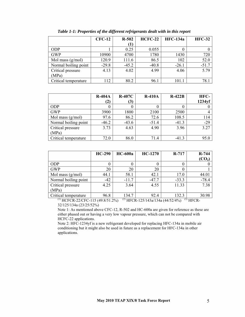
May 2010 TEAP XIX/8 Task Force Report 5
Table 1-1: Properties of the different refrigerants dealt with in this report
CFC-12 R-502(1)
HCFC-22 HFC-134a HFC-32
ODP 1 0.25 0.055 0 0GWP 10900 4700 1780 1430 720Mol mass (g/mol) 120.9 111.6 86.5 102 52.0Normal boiling point -29.8 -45.2 -40.8 -26.1 -51.7Critical pressure (MPa)
4.13 4.02 4.99 4.06 5.79
Critical temperature 112 80.2 96.1 101.1 78.1
R-404A (2)
R-407C (3)
R-410A R-422B HFC-1234yf
ODP 0 0 0 0 0GWP 3900 1800 2100 2500 4Mol mass (g/mol) 97.6 86.2 72.6 108.5 114Normal boiling point -46.2 -43.6 -51.4 -41.3 -29Critical pressure (MPa)
3.73 4.63 4.90 3.96 3.27
Critical temperature 72.0 86.0 71.4 -41.3 95.0
HC-290 HC-600a HC-1270 R-717 R-744 (CO2)
ODP 0 0 0 0 0GWP 20 20 20 0 1Mol mass (g/mol) 44.1 58.1 42.1 17.0 44.01Normal boiling point -42 -11.7 -47.7 -33.3 -78.4Critical pressure (MPa)
4.25 3.64 4.55 11.33 7.38
Critical temperature 96.8 134.7 92.4 132.3 30.98(1) HCFCR-22/CFC-115 (49.8/51.2%) (2) HFCR-125/143a/134a (44/52/4%) (3) HFCR-32/125/134a (23/25/52%) Note 1: As mentioned above CFC-12, R-502 and HC-600a are given for reference as these are either phased out or having a very low vapour pressure, which can not be compared with HCFC-22 applications. Note 2: HFC-1234yf is a new refrigerant developed for replacing HFC-134a in mobile air conditioning but it might also be used in future as a replacement for HFC-134a in other applications.


May 2010 TEAP XIX/8 Task Force Report 7
2 Refrigerants for High Ambient Temperature Air Conditioning Air conditioning around the world is generally done using either unitary (air-to-air) equipment or liquid chillers. Air-to-air systems are the primary focus of this analysis and consist of many sub-categories. On a global basis, air-cooled air conditioners and heat pumps range in sizes from 2.0 kW to 420 kW. For higher capacities, water-cooled chillers tend to be the dominant technology. Nearly all air-cooled air conditioners and heat pumps manufactured prior to 2000 used HCFC-22 as the working fluid. The vast majority of the installed base of unitary equipment in usage world-wide employs HCFC-22, although some older equipment and niche applications utilise other refrigerants /Cal04, UNEP06/.
Air-cooled air conditioners and heat pumps generally fall into four distinct categories, based primarily on capacity or application: small self-contained air conditioners (window-mounted and through-the-wall air conditioners); non-ducted or duct-free split residential and commercial air conditioners; ducted, split residential air conditioners; and ducted commercial split and packaged air conditioners.
The objective of this study is to assess the impact of high ambient conditions (above 40°C) on the performance of the current HCFC-22 replacements for air conditioners. The governing thermodynamic properties and principles result in a declining capacity and efficiency for all refrigerants as the heat-rejection (refrigerant condensing) temperature increases, including HCFC-22. However, some of the HCFC-22 replacements exhibit greater degradation in capacity and efficiency than HCFC-22 under high ambient conditions. Currently, the most widely applied replacements for HCFC-22 in unitary air conditioning applications are HFC blends, primarily R-410A and R-407C. Hydrocarbons are also being used in some low refrigerant-charge applications.
R-410A and R-407C both have lower critical temperatures59 than HCFCR-22. This occurs because HFC-125 (a component of both R-407C and R-410A) has a comparatively low critical point temperature of 66.0°C (150°F). The critical point temperature is important because refrigerants having a low critical point temperature will exhibit a steeper decline in capacity with increased ambient (outdoor) temperatures than refrigerants having higher critical point temperatures. This steeper decline in capacity is of particular
59 Critical temperature is the temperature above which a refrigerant cannot be condensed regardless of pressure. Being above critical temperature prohibits condensation on the heat rejection side of the conventional vapour-compression cycle.

May 2010 TEAP XIX/8 Task Force Report 8
importance in geographic regions, which have cooling design temperatures approaching the critical point temperature of the refrigerant.
Table 2-1 shows typical air conditioning 99% design condition data from the ASHRAE Handbook of Fundamentals for several cities /ASH05/. These data show that there are many regions globally where outdoor design conditions are high enough to result in condenser temperatures near or above the critical temperature of HFC-125. It should be pointed out that Table 2-1 presents design conditions and not the annual distribution of hours at specific ambients. Obviously, in some geographic locations the annual distribution of hours at specific temperatures will favour the higher ambient conditions. The ASHRAE Handbook of Fundamentals provides ‘bin” data (temperature versus 2.5 °C temperature bins) for many global localities.
For example, it can be observed that a high temperature of 50.4 °C is expected once every 50 years at Kuwait International Airport.
Table 2-1: Air Conditioning Design Temperatures, °C
Location 10 Years 20 Years 50 Years Phoenix, Arizona 47.5 48.2 49.2 Sacramento, California 43.5 44.5 45.7 Imperial, California 49.9 51.0 52.5 Salt Lake City, Utah 40.0 40.7 41.7 Las Vegas, Nevada 46.0 46.6 47.5 Bahrain Intl Airport 45.6 46.4 47.5 Kuwait Intl Airport 51.0 51.6 52.3 Jeddah, Saudi Arabia 47.7 48.9 50.4 Riyadh [ASUD AFB], Saudi Arabia 46.6 47.1 47.6 Source: ASH05Methodology This analysis has used two methodologies to assess the high ambient performance of HCFC-22 replacements:
1. the use of a simulation model for the thermodynamic analysis of the vapour compression cycle, called cycle analysis, to assess the high ambient performance of the most commonly considered HCFC-22 replacements, and
2. the use of published performance data of commercially available air-conditioners that use HFC blends.
2.1 Refrigerant Options To limit the scope of the study, the refrigerants compared herein are those already commercialised as well as those prominently addressed in prior published studies /Cal04, Dom02, Mot00, Pay02/, namely: HCFC-22, HFC-32, HFC-134a, HC-290 (propane), R-407C, R-410A, HC-600a (isobutane), and CO2.

May 2010 TEAP XIX/8 Task Force Report 9
The analysis of CO2 was based on a simple transcritical cycle analysis, which results in lower efficiencies than would be expected with a fully optimised CO2 system since a fully optimised CO2 system would likely utilise additional components (a suction line heat exchanger, expander or ejector) to partially offset the efficiency losses associated with the transcritical operation.
Some parameters of selected refrigerants were given in Table 1-1.
2.2 Cycle Analysis (Computation Model) The various refrigerants under consideration were evaluated in a modified ideal cycle analysis using the NIST program Cycle_D /Dom03/. The Cycle_D input conditions selected for the analysis were consistent with those used in prior studies /Cal04/. The conditions and assumptions used are given below.
CYCLE_D requires the system capacity as one of its inputs. Thus, the capacity does not decrease as the condensing temperature. Instead, the Cycle_D model calculates the compressor volumetric displacement (or flow) required to deliver the specified cooling capacity. However, the calculated volumetric capacity provides a good estimate of the expected cooling capacity decrease with increasing ambient temperatures. For each refrigerant, the outdoor ambient was allowed to increase to the point where CYCLE_D provided a warning that the conditions were within 15 K of the critical temperature, because the model accuracy above this temperature is in doubt.
Table 2-2: Cycle Analysis Input Parameters
Cycle Analysis Input Parameters Average Evaporating Temperatures Input Temperature 10 C (50 F) Superheat 5 C (9 F) Average Condensing Temperatures Input Temperature 40 – 80 C (104 – 176 F) Subcooling 5 C (9 F) Compressor Efficiencies Isentropic 73% Volumetric 100% Motor 92% Piping Losses Suction None Discharge None Suction or Discharge Line Heat Exchanger None Fan and Control Power Indoor Fan None Outdoor Fan None Controls None

May 2010 TEAP XIX/8 Task Force Report 10
2.3 High Ambient Performance based on Cycle Analysis For air cooled air conditioners, the capacity and efficiency decrease rather significantly as the outdoor temperature increases. The principal focus in the model run outputs was on system efficiency and capacity. The Coefficient of Performance (COP)60 results are presented in Table 2-3. The capacity relative to the HCFC-22 baseline system is shown in Table 2-4. A condensing temperature of 65 °C corresponds to an ambient temperature of approximately 55 °C.
Table 2-3: COP as a function of the condensing temperature (°C)
Refrigerant Condensing temperature (°C) Refrigerant 35 40 50 60 65 HCFC-22 6.28 5.08 3.57 2.64 2.29 HCFC-22 HFC-32 6.03 4.85 3.35 2.43 2.09 HFC-32 HFC-134a 6.41 5.18 3.62 2.66 2.30 HFC-134a HC-290 6.31 5.09 3.54 2.58 2.23 HC-290 R-407C 6.23 5.01 3.47 2.51 2.15 R-407C R-410A 6.01 4.800 3.27 2.32 1.95 R-410A HC-600a 6.54 5.30 3.74 2.78 2.42 HC-600a
Table 2-3 illustrates the decrease in efficiency as the ambient temperature increases. The efficiency of an HCFC-22 system decreases by more than 60% from the moderate condition of 35°C ambient to a temperature of about 65°C ambient. This is a direct result of the fact that the "thermal head" against which the air conditioner is working nearly doubles between the moderate and extreme conditions.
Table 2-4: Capacity Relative to HCFC-22 (% of HCFC-22)
Refrigerant Condensing temperature
(°C) Refrigerant 40 50 60 65 HCFC-22 100 100 100 100 HCFC-22 HFC-32 100 100 99 98 HFC-32 HFC-134a 100 99 97 96 HFC-134a HC-290 100 98 96 95 HC-290 R-407C 100 97 94 92 R-407C R-410A 100 97 93 90 R-410A HC-600a 100 100 99 97 HC-600a
Note: Units designed to have same capacity at 40 °C 60 Coefficient of Performance (COP)׃ ratio of the cooling (or heating) capacity to the compressor power input.
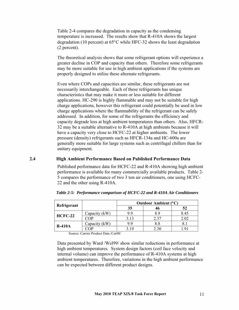
May 2010 TEAP XIX/8 Task Force Report 11
Table 2-4 compares the degradation in capacity as the condensing temperature is increased. The results show that R-410A shows the largest degradation (10 percent) at 65°C while HFC-32 shows the least degradation (2 percent).
The theoretical analysis shows that some refrigerant options will experience a greater decline in COP and capacity than others. Therefore some refrigerants may be more suitable for use in high ambient applications if the systems are properly designed to utilise these alternate refrigerants.
Even where COPs and capacities are similar, these refrigerants are not necessarily interchangeable. Each of these refrigerants has unique characteristics that may make it more or less suitable for different applications. HC-290 is highly flammable and may not be suitable for high charge applications, however this refrigerant could potentially be used in low charge applications where the flammability of the refrigerant can be safely addressed. In addition, for some of the refrigerants the efficiency and capacity degrade less at high ambient temperatures than others. Also, HFCR-32 may be a suitable alternative to R-410A at high ambients because it will have a capacity very close to HCFC-22 at higher ambients. The lower pressure (density) refrigerants such as HFCR-134a and HC-600a are generally more suitable for large systems such as centrifugal chillers than for unitary equipment.
2.4 High Ambient Performance Based on Published Performance Data Published performance data for HCFC-22 and R-410A showing high ambient performance is available for many commercially available products. Table 2-5 compares the performance of two 3 ton air conditioners, one using HCFC-22 and the other using R-410A.
Table 2-5: Performance comparison of HCFC-22 and R-410A Air Conditioners
Outdoor Ambient (°C) Refrigerant 35 46 52
Capacity (kW) 9.9 8.9 8.45 HCFC-22 COP 3.13 2.37 2.02 Capacity (kW) 9.9 8.8 8.1 R-410A COP 3.19 2.30 1.91
Source: Carrier Product Data /Car08/ Data presented by Ward /Wel99/ show similar reductions in performance at high ambient temperatures. System design factors (coil face velocity and internal volume) can improve the performance of R-410A systems at high ambient temperatures. Therefore, variations in the high ambient performance can be expected between different product designs.

May 2010 TEAP XIX/8 Task Force Report 12
2.5 Overview The current refrigerants of choice for unitary air conditioning are HCFC-22, R-407C and R-410A. R-410A is the most widely used replacement for HCFC-22 in developed countries, but R-407C is also used as a replacement in some applications. The following are the most likely replacements for HCFC-22 for use in high ambient temperature climates.
2.5.1 R-410A
R-410A systems have been demonstrated to operate acceptably at ambient temperatures up to 52°C. The performance (capacity and efficiency) of R-410A air-conditioners falls off more rapidly than HCFC-22 systems at high ambient temperatures (above 40°C) as shown in Tables 2-3, 2-4, 2-5 and Figures 2-1 and 2-2. The optimum selection of compressor, airflow, condenser design, and expansion device can reduce the performance losses at high ambient temperatures /Bat04/. Even with optimised designs, when applying R-410A systems that will operate a significant number of hours at high ambient temperatures, the system designer should take into consideration the reduced high ambient capacity when sizing the equipment. For cases where the base capacity of the unit would need to be increased to meet the building load at extreme ambient temperatures the following rule of thumb should be sufficient in estimating the cost impact. For an R-410A, the cost of increasing the capacity by 10 percent will increase the cost of the unit approximately 3 percent.
2.5.2 HC-290
HC-290 has performance characteristics similar to HCFC-22. The characteristics are close enough that the current products that employ HCFC-22 could be re-engineered to employ HC-290. HC-290 has successfully been commercialised as an HCFC-22 replacement in low charge, room and portable air-conditioner applications of less than 4 kW /Dev05/. HC-290 shows a 5 percent reduction in capacity at 65°C, see Table 2-4.
IEC standard 60335-2-40, /IEC05/, has established the criteria for determining the maximum charge limit for highly flammable refrigerant applications. The reason for limiting the refrigerant charge is concern about the safety of larger charges of hydrocarbons. In direct expansion (DX) systems, a single refrigerant line or heat exchanger failure could discharge the refrigerant into the conditioned space; potentially allowing the refrigerant concentration in the space to exceed the lower flammability limit, LFL of the refrigerant. Safely and cost effectively applying hydrocarbons to larger unitary systems will be a significant technical challenge.
May 2010 TEAP XIX/8 Task Force Report 13
2.5.3 R-407C
R-407C systems will typically perform in nearly the same way as HCFC-22 systems at typical ambient temperatures. At ambient temperatures above 40°C, R-407C systems show less degradation of capacity and efficiency than R-410A systems. However, an R-407C system will still exhibit a capacity approximately 8% less than an HCFC-22 system at a condensing temperature of 65°C (Table 2-4). Since R-407C refrigerant requires only modest modifications to existing HCFC-22 systems, it has also been used as a transitional refrigerant in equipment originally designed for HCFC-22.
There are currently R-407C air conditioning products widely available in Europe, Japan and other parts of Asia.
2.5.4 HFC-32
HFC-32 is being considered as an alternative to R-410A. HFC-32 will have higher efficiency and capacity at high ambient temperatures. HFC-32 will have a capacity approximately 2 percent less than an HCFC-22 system at 65 °C condensing temperature. While HFC-32 systems are currently under development, none are currently available in the market.
2.5.5 HFC-134a and HC-600a
HFC-134a and HC-600a would seem attractive from the point of view that they have similar performance to HCFC-22 at high ambient temperatures. However, both of these refrigerants are low-pressure refrigerants. Therefore, extensive redesign of the base system components would be required in order to achieve the same capacity and efficiency of the HCFC-22 system. Design changes would include larger displacement compressors, increased heat exchanger areas and increases in the piping sizes used in heat exchangers and inter-connecting tubing. All of these changes would lead to substantial increases in the product cost. In addition, additional design changes would be required with HC-600a to address the high flammability of this refrigerant. Therefore, HFC-134a and HC-600a are not considered the most viable options to replace HCFC-22 in unitary air-conditioning applications.
2.5.6 CO2
Carbon dioxide (R-744) offers a number of desirable properties as a refrigerant: readily available, low-toxicity, low GWP and low cost. These desirable characteristics are offset by the fact that CO2 has a very low critical temperature (31°C) and will operate above critical point conditions in most air-conditioning applications. Operation at these conditions results in a significant degradation in both capacity and COP at high ambient temperatures.

May 2010 TEAP XIX/8 Task Force Report 14
These losses can be partially offset by the addition of internal cycle heat exchangers and expanders or ejectors. However, CO2 systems are not expected to provide a good alternative to HCFC-22 or HFC refrigerants when being applied in high temperature regions (> 40°C).
2.5.6 HFC Replacements
Alternatives to HFC refrigerants for air-conditioning applications are in the early stages of development. A number of new refrigerants are being investigated to replace R-407C and R-410A, including HFC-1234yf and blends of other HFC refrigerants with HFC-1234yf.
While refrigerant manufacturers are believed to be working to qualify other chemicals or blends that might be new, their development has not progressed to the point where they are available to unitary equipment manufacturers for evaluation and equipment development.
Therefore, it is premature to recommend alternatives to R-410A or R-407C at this early stage of the development other than HC-290, which may be applicable in very low charge (< 250 g) applications when appropriate safety and application requirements are considered.
2.6 Concluding Remarks These studies have highlighted the primary refrigerant options that could be utilised to design both low-ODP and low-GWP replacements for HCFC-22 in air-conditioning applications for use in high ambient environments. In the near term, regions with hot climates should be able to rely on the refrigerants and technologies that are currently commercially available to replace HCFC-22 (R-407C, R-410A and HC-290).
However, when replacing HCFC-22 products with those using R-410A or R-407C the application engineer will need to take into consideration the reduced capacity at the design ambient temperature when sizing the equipment for the design cooling load. The application engineer should consult the application data published by the manufacturer when making sizing decisions. In most cases R-410A or R-407C will only need to be sized 5-10% larger than HCFC-22 equipment to compensate for the lower capacity at ambient temperatures up to 50 °C. The increased cost of oversizing the equipment will be about 3% for a 10% increase in capacity.
When replacing HCFC-22 in low charge applications (small window and portable room air conditioners), the system designer may want to consider the use of HC-290. When replacing HCFC-22 with HC-290 it may be needed to limit the usage of HC-290 to low charge applications (<250 g) and make the appropriate design changes to comply with all applicable codes and standards. It is stressed that HC-290 should not be used as a retrofit solution, since

May 2010 TEAP XIX/8 Task Force Report 15
appropriate safety considerations need to be addressed in the fundamental design of the product.
HFC-32 is likely to become a longer-term replacement for R-410A. It has a GWP approximately 32% of that of R-410A and exhibits much better high ambient performance than R-410A. In addition, the design changes required to convert from R-410A to HFC-32 should be minor.
HFC-134a and HC-600a would seem attractive from the point of view that they have similar performance to HCFC-22 at high ambient temperatures. However, both of these refrigerants are low-pressure refrigerants. The use of these low pressure refrigerants would require extensive redesign of the base system components in order to achieve the same capacity and efficiency of the HCFC-22 system. Therefore, HFCR-134a and HC-600a are not considered cost effective options to replace HCFC-22 in unitary air-conditioning applications.
A number of low GWP alternatives to HFC refrigerants are currently under development. However, because these refrigerants are in the early stages of development it is premature to list them as options to the current HCFC alternatives.
In the longer term, as non-ODP and low-GWP technologies are developed to replace current HCFC-22, R-407C and R-410A products, equipment designed to operate with acceptable efficiency and capacities at the extreme environment conditions should become widely available in both developed and developing countries.
2.7 References /ASH05/ ASHRAE Handbook of Fundamentals, 2005 Edition, Chapter 28, CD
with Data tables, 2005 /Bat04/ D. J. Bateman, Performance of DuPont™ Suva® 410A, Compared to
R-22, at High Ambient Temperatures, bulletin K-05738, DuPont Chemicals, Wilmington, DE, USA, 2004.10
/Cal04/ J. M. Calm and P. A. Domanski, “R-22 Replacement Status,” ASHRAE Journal, 46(8):29-39, August 2004; erratum, 46(10):8, October 2004
/Dom02/ P. A. Domanski and W. V. Payne, Properties and Cycle Performance of Refrigerant Blends Operating Near and Above the Refrigerant Critical Point – Task 2: Air Conditioner System Study, report ARTI-21CR/605-50010-01-Pt. 2, October 2002
/Dom03/ P. A. Domanski, D. A. Didion, and J. S. W. Chi, CYCLE_D: NIST Vapor-Compression Design Program (version 3.0), Standard reference database 49, National Institute of Standards and Technology (NIST), Gaithersburg, MD, USA, 2003
/Dev05/ Devotta, S., Padalkar, A.S. and Sane, N. K., Performance assessment of HC-290 as a drop-in substitute to HCFC-22 in a window air

May 2010 TEAP XIX/8 Task Force Report 16
conditioner”, International Journal of Refrigeration, 28, 594-604, 2005.
/IEC05/ IEC, Household and similar electrical appliances - Safety - Part 2-40: Particular requirements for electrical heat pumps, air-conditioners and dehumidifiers, Edition 4.2, IEC Central Office, Geneva, Switzerland, 2005.
/Mot00/ S. F. Y. Motta and P. A. Domanski, “Performance of R-22 and Its alternatives Working at High Outdoor Temperatures, Proceedings of the Eighth International Refrigeration Conference, (2000.07.25-28), Purdue University, West Lafayette, Indiana, USA, 47-54. 2000.07
/Pay02/ V. W. Payne and P. A. Domanski, Comparison of an R-22 and an R-410A Air Conditioner Operating at High Ambient Temperatures, paper R2-1, Proceedings of the Ninth International Refrigeration and Air Conditioning Conference (2002.07.16-19), Purdue University, West Lafayette, IN, USA, 2002
/UNEP06/ Report of the Refrigeration, Air-Conditioning and Heat Pumps Technical Options Committee (RTOC) – 2006 Assessment, IBSN 978-92-807-2822-4, United Nations Environment Programme (UNEP) Ozone Secretariat, Nairobi, Kenya, January 2007
/Wel99/ W. D. Wells, D. B. Bivens, M. Yokozeki, and C. K. Rice, R-410A performance near critical point, presentation, ASHRAE Annual Meting (Seattle, WA, USA), 1999.06.21

May 2010 TEAP XIX/8 Task Force Report 17
3 Refrigerants for High Ambient Temperature Commercial Refrigeration Commercial refrigeration covers a wide variety of equipment, and can be classified in three categories: stand-alone equipment, condensing units, and centralized systems. According to the type of system, the refrigerant charge varies from hundreds of grams to a thousand kilograms. Moreover, depending on the system type, the refrigerant choice is different. Usual choices have been׃ HFC-134a with a relatively low volumetric capacity is used in small equipment (most stand-alone equipment and some condensing units) and preferably at the medium level of the evaporating temperature. Refrigerants such as HCFC-22 or R-404A, with a larger volumetric capacity, are used in large centralized systems for all levels of evaporating temperatures.
For centralized systems, the cascading system is currently taking a market-share in supermarkets in Europe, with CO2 at the low-temperature level and a variety of refrigerants at the high-temperature level, including ammonia, propane, propylene, as well as R-404A.
In order to define a range of ambient temperatures, moderate climate exhibits a yearly average temperature between 12 and 15°C with 2 to 3 months where the average temperatures are around 20 to 25°C and some hours of the day up to 35°C. Hot climates exhibit average yearly temperatures around 20°C with several months with average temperature in the range of 30°C and many hours of the day with temperature higher than 40°C.
3.1 Small Commercial Refrigeration Stand alone equipment encompasses a wide variety of equipment types: vending machines, ice machines, ice cream freezers, water fountains, glass door bottle coolers, and plug-in display cabinets. For levels of temperatures varying from -15°C to 0°C and cooling capacities varying from tens of Watts to 200 W, lower volumetric capacity refrigerants such as HFC-134a or HC-600a are the preferred choice. Until now all those systems have been designed based on a single-stage system and the refrigerants have been chosen based on this constraint.
For evaporating temperature varying from -35°C to -20°C, one can find R-404A or HC-290. Exceptions exist, some companies are choosing CO2 (R-744), even if this refrigerant is not energy efficient in hot climates.
Table 1-1 above summarised the main thermodynamics and environmental properties (including GWP and ODP values, reference: 2006 RTOC report) of refrigerants that have been used or could be used in small commercial refrigeration equipment.

May 2010 TEAP XIX/8 Task Force Report 18
3.1.1 HFC-134a and hydrocarbons
Stand-alone equipment and some condensing units (those with smaller refrigeration capacity) have been developed successively with CFC-12 and since 1992 with HFC-134a. The use of isobutane (HC-600a) in domestic refrigeration began in Europe in 1994. The significant introduction of this refrigerant in refrigerators has also led to its use in small commercial equipment such as water fountains, and in equipment having a refrigerant charge lower than 150 g. For ice-cream freezers, propane (HC-290) has been introduced since 2000 by large food companies that own that equipment installed in all types of food outlets. Owing to their relatively high critical temperatures, HFC-134a, HC-600a and HC-290 are well suited to hot climate applications. The limitation for the use of hydrocarbons is the refrigerant charge, for safety purpose.
3.1.2 CO2
For larger refrigerant charges (in the range of several hundreds grams), owing to flammability risks, some global companies have decided to develop the use of CO2 (R-744) for vending machines. Owing to the low critical temperature of this refrigerant (31°C), those systems experiment very high pressure (above 10 MPa) and there is no more condensation at the high-pressure side, so the usual phase-change cycle (condensation at the high pressure and evaporation at the low pressure) becomes a transcritical cycle (cooling of a dense gas phase at the high pressure and evaporation at the low pressure). The efficiency of such a transcritical cycle is relatively low and additional components such as liquid/vapour heat exchangers are necessary to reach acceptable energy efficiency at high temperature. In summary, CO2 is not a suitable fluid for hot climates, due to relatively poor energy efficiency in those conditions. Nevertheless, for some families, stand-alone equipment has been developed with CO2; until now the market share is limited.
3.1.3 HFC-1234yf
Based on the European directive 40/2006, HFC-134a will be banned in new mobile air-conditioning systems in Europe progressively from 2011 to 2017. This regulation has led the main chemical companies to develop new refrigerants with very low GWP. The first one that has been thoroughly studied is 1,1,1,2 tetra-fluoro-propylene, named HFC-1234yf (also given the acronym HFO by chemical manufacturers, which stands for Hydro-Fluoro-Olefine). The thermodynamic properties of this refrigerant are very close to those of HFC-134a (see Table 1-1). This refrigerant is very mildly flammable and its toxicity is low. HFC-1234yf is expected to be mass-produced by 2011 and 2012. With small adaptation of capillary tubes, it can be used in small commercial refrigeration similar to HFC-134a. It has to be noted that, because this refrigerant consists of a larger molecule than HFC-134a, its discharge temperature is significantly lower and therefore it would be even more suitable for hot climates.
May 2010 TEAP XIX/8 Task Force Report 19
3.2 Large Centralised Systems (Supermarket Refrigeration) It has to be mentioned that, in the seventies, Europe progressively enforced a lower temperature for conservation of frozen food: from -15°C to -18°C at the core of products. The consequence of a lower product temperature is a lower evaporating temperature moving from typically -35°C to -38°C or even lower. Even in a moderate climate, this change of evaporating temperature has led to a too high discharge temperature at the high-pressure side of compressors using HCFC-22. R-502, having 51.2% of CFC-115 blended with HCFC-22, exhibits a lower discharge temperature because CFC-115 has a lower heating capacity. Owing to this fact, there has been a progressive shift from HCFC-22 to R-502 in centralized supermarket systems. R-404A and R-507 have been formulated in order to replace R-502 and also comprise high molecular weight molecules leading to lower discharge temperatures compared to HCFC-22. In summary, HCFC-22 is not even the best designed molecule for high ambient temperatures if the evaporating temperature is lower than -35°C.
Hot climates imply high condensing temperatures and, for usual refrigerants, high condensing pressures. Such high pressures and temperatures have several consequences:
The energy penalty for a single-stage system is about 1.5% per K of higher condensing temperature, meaning that COPs of medium and low-temperature commercial systems are lower by 15 to 25% in hot climates compared to moderate ones
For low-temperature applications (frozen food), the discharge temperatures of the compressor with HCFC-22 are so high that liquid injection is necessary either at the suction port or at an intermediate stage if the compressor design allows such an injection.
High temperatures at the compressor discharge line imply energy losses and possible decomposition of the lubricant when temperatures become higher than 140°C. As indicated above, HCFC-22 is not the best refrigerant to be used in a direct expansion system for low-temperature applications (evaporating temperature below –35°C) with a condensing temperature above 50°C.
Several technical options have been developed over time in order to improve energy efficiency of low-temperature applications and also to limit the discharge temperature at the compressor discharge port. Those options have been developed over many years in the industrial food sector. Some of those options are used in supermarkets especially in Northern Europe for the more advanced ones.
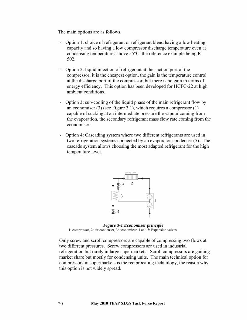
May 2010 TEAP XIX/8 Task Force Report 20
The main options are as follows.
- Option 1: choice of refrigerant or refrigerant blend having a low heating capacity and so having a low compressor discharge temperature even at condensing temperatures above 55°C, the reference example being R-502.
- Option 2: liquid injection of refrigerant at the suction port of the compressor; it is the cheapest option, the gain is the temperature control at the discharge port of the compressor, but there is no gain in terms of energy efficiency. This option has been developed for HCFC-22 at high ambient conditions.
- Option 3: sub-cooling of the liquid phase of the main refrigerant flow by an economiser (3) (see Figure 3.1), which requires a compressor (1) capable of sucking at an intermediate pressure the vapour coming from the evaporation, the secondary refrigerant mass flow rate coming from the economiser.
- Option 4: Cascading system where two different refrigerants are used in two refrigeration systems connected by an evaporator-condenser (5). The cascade system allows choosing the most adapted refrigerant for the high temperature level.
Figure 3-1 Economiser principle
1: compressor, 2: air condenser, 3: economizer, 4 and 5: Expansion valves
Only screw and scroll compressors are capable of compressing two flows at two different pressures. Screw compressors are used in industrial refrigeration but rarely in large supermarkets. Scroll compressors are gaining market share but mostly for condensing units. The main technical option for compressors in supermarkets is the reciprocating technology, the reason why this option is not widely spread.

May 2010 TEAP XIX/8 Task Force Report 21
Figure 3-2 Cascade system
1: high temperature compressor, 6: low temperature compressor, 2: air condenser, 3 and 7: refrigerant receivers,
4 and 8: Expansion valves, 9: low temperature evaporator, 5: evaporator-condenser The cascading system design is gaining market-share in supermarkets in Europe, with CO2 at the low-temperature level and a variety of refrigerants at the high-temperature level, among which are: ammonia, propane, propylene, and also R-404A. This design is more costly than the simple one-stage system but, in terms of energy efficiency, it is far better with energy gains in the range to 15 to 30% compared to the single-stage system operating between -35°C evaporating temperature and 50°C.
3.2.1 Current Refrigerants in Use
HCFC-22 is the refrigerant still in use in many developed countries, especially in the U.S. until 2010 and in all developing countries under a wide range of ambient temperature conditions, but with very different evaporating temperatures. In many cases, the evaporating temperature will be fixed at a level where the discharge temperature of compressors is still acceptable (lower than 140°C). Owing to its more stringent regulation (2037/2000), Europe banned HCFC-22 in new commercial refrigeration equipment as of 2000. Nevertheless, the installed base using HCFC-22 is still important and intermediate HFC blends such as R-422D or R-427A have been developed in order to make retrofit from HCFC-22 to those blends easy. These blends, having HFC-125 as a component, exhibit lower discharge temperatures compared to HCFC-22. Nevertheless all HFC-125 based blends have high GWPs. R-404A, which has replaced R-502 and sometimes also HCFC-22 in commercial centralized systems, presents lower energy efficiency in hot condensing conditions owing to its relatively lower critical temperature (Tc = 72°C) compared to R-502 (Tc = 80°C).
It has to be underlined that a “free” sub-cooling of the refrigerant is available when supermarkets are air-conditioned: the refrigerant leaves the high-pressure receiver at, for example, 50°C or above, the long liquid lines (about 100 m or more) are installed in the sales area, where the temperature is about 25°C, and so the refrigerant enters the expansion valve at about 30°C. This

May 2010 TEAP XIX/8 Task Force Report 22
temperature decrease leads to better energy efficiency for the refrigeration system, but it has been paid for by the energy consumption of the air conditioning system.
In the absence of the “free” cooling, an interesting design has been developed in order to improve the cooling capacity and the energy efficiency in very hot outdoor conditions. It is the “option 3” presented above, which consists of installing a small refrigerating system working typically with HFC-134a, whose purpose is only to cool the liquid phase of R-404A or even HCFC-22 after condensation, in order to generate a large sub-cooling, typically down to 10°C. The drawback is that the liquid line has to be insulated over its entire length.
3.2.2 Hydrocarbons, Ammonia, HFCs, and Indirect Systems for Supermarkets
In Northern Europe, some equipment manufacturers have developed refrigeration systems using hydrocarbons, either HC-290 (propane) or HC-1270 (propylene). For centralised systems installed in supermarkets with cooling capacities varying from 20 kW to 1.2 MW, two different types of equipment have to be distinguished:
- condensing units such as installed in small supermarkets or convenience stores with refrigerant charge of HC-290 up to 5 kg in direct expansion systems. The number of those systems can be estimated at several hundred, mainly in Germany, the United Kingdom, and Denmark
- centralised indirect systems with HC-1270 or HC-290 or R-404A as primary refrigerants.
- in Germany, many so called “discounter” supermarkets use HC-290 for display cases with short lines, so-called distributed systems, with HC-290 charges varying from 500 g to 2.5 kg.
For centralised systems, owing to the large refrigerant charge and the number of fittings when some hundreds of evaporators are installed in the sales area, it is impossible to use direct expansion systems with flammable refrigerants. Indirect systems have been used in commercial refrigeration for more than ten years (see Figure 3-3).
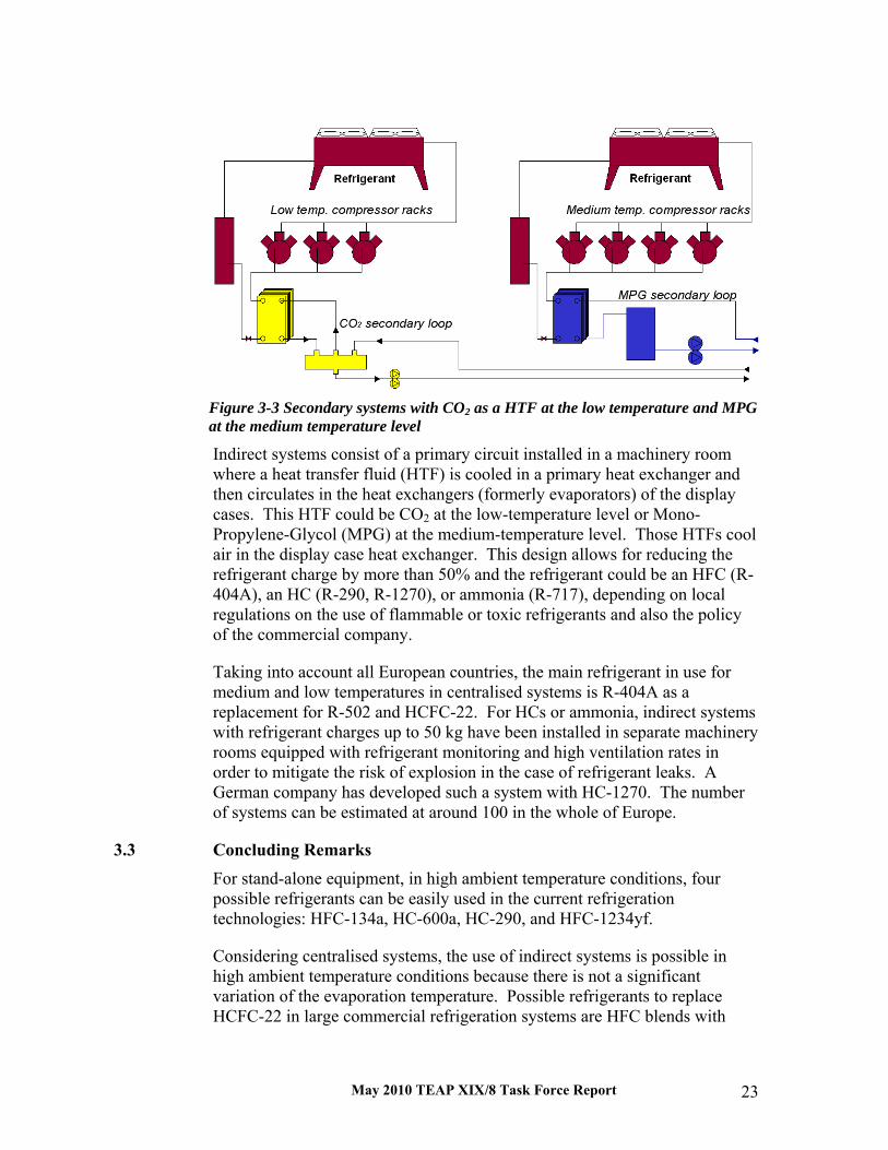
May 2010 TEAP XIX/8 Task Force Report 23
Figure 3-3 Secondary systems with CO2 as a HTF at the low temperature and MPG at the medium temperature level
Indirect systems consist of a primary circuit installed in a machinery room where a heat transfer fluid (HTF) is cooled in a primary heat exchanger and then circulates in the heat exchangers (formerly evaporators) of the display cases. This HTF could be CO2 at the low-temperature level or Mono-Propylene-Glycol (MPG) at the medium-temperature level. Those HTFs cool air in the display case heat exchanger. This design allows for reducing the refrigerant charge by more than 50% and the refrigerant could be an HFC (R-404A), an HC (R-290, R-1270), or ammonia (R-717), depending on local regulations on the use of flammable or toxic refrigerants and also the policy of the commercial company.
Taking into account all European countries, the main refrigerant in use for medium and low temperatures in centralised systems is R-404A as a replacement for R-502 and HCFC-22. For HCs or ammonia, indirect systems with refrigerant charges up to 50 kg have been installed in separate machinery rooms equipped with refrigerant monitoring and high ventilation rates in order to mitigate the risk of explosion in the case of refrigerant leaks. A German company has developed such a system with HC-1270. The number of systems can be estimated at around 100 in the whole of Europe.
3.3 Concluding Remarks
For stand-alone equipment, in high ambient temperature conditions, four possible refrigerants can be easily used in the current refrigeration technologies: HFC-134a, HC-600a, HC-290, and HFC-1234yf.
Considering centralised systems, the use of indirect systems is possible in high ambient temperature conditions because there is not a significant variation of the evaporation temperature. Possible refrigerants to replace HCFC-22 in large commercial refrigeration systems are HFC blends with

May 2010 TEAP XIX/8 Task Force Report 24
high GWP, such as R-404A or even R-422D or R-427A, but for those two blends the refrigerating capacity could be lower of about 5% and the efficiency also lower of 5 to 10%. R-407C is used in centralised systems in Japan and exhibits the lowest GWP (~1800) of all those HFC blends. HCs such as HC-290 and HC-1270 can be used in hot climates and they exhibit relatively low discharge temperatures compared to HCFC-22. Nevertheless, refrigerant quantities have to be limited and direct expansion systems should have a circuit that is almost completely welded in order to limit refrigerant leaks. Thorough safety precautions have to be taken, one of the most relevant ones being charge reduction by using the indirect system concept. Owing to the development of HFC-1234yf, new blends with very low GWP can be expected in the next three years. In order to mitigate environmental impact, safety, and energy efficiency, those new blends will possibly be used in indirect systems or cascading systems, with CO2 at the low temperature level used as a refrigerant or as a heat transfer fluid.
3.4 References /Bax03a/ Baxter, V.D. (editor), 2003a, Advanced supermarket
refrigeration/Heat recovery systems. Vol. 1, Executive summary. IEA Heat Pump Center, 73 pp (ISBN: 90-73741-48-3).
/Bax03b/ Baxter, V.D. (editor), 2003b, Advanced supermarket refrigeration/Heat recovery systems. Vol. 2, Country Reports. IEA Heat Pump Center, 73 pp (CD-ROM ISBN: 90-73741-49-1).
/Coc04/ Coca Cola, 2004, The Coca Cola company - Alternative refrigeration background. Refrigerants Naturally Conference, Brussels, 2004.
/EU00/ Regulation (EC) no. 2037/2000 the European Parliament and of the Council of 29 June 2000 on substances that deplete the ozone layer.
/Gir04/ Girotto, S., Minetto, S. and Nekså, P., (2004): Commercial Refrigeration with CO2 as Refrigerant, Experimental Results, Int. J of Refrigeration, Vol 27 (7), November 2004
/IPCC05/ IPCC, 2005, Safeguarding the ozone layer and the global climate system. Issues related to Hydrofluorocarbons and Perfluorocarbons. Cambridge University Press. 2005. ISBN: 13-978-0-521-68206-0.
/Rhie08/ Rhiemeier J-M., Harnisch J., Ters Ch., Kauffeld M., Comparative assessment of the climate relevance of supermarket refrigeration systems and equipment. Research report 206 44 300 – UBA-FB 001180-e March 2009
/RAC01/ Why a secondary system should be considered first. Refrigeration and Air Conditioning, December 2001, pp. 26-27.
/UNEP06/ UNEP, 2006 Refrigeration, AC and Heat Pumps Assessment Report, ISBN 978-92-807-2822-4 UNEP Nairobi, January 2007.

May 2010 TEAP XIX/8 Task Force Report 25
4. Refrigerants for Deep Mines The focal considerations for deep mines differ in several respects from those for applications addressed in preceding sections of this report:
• The thermal loads are much less dependent on ambient air temperatures.
• The cooling requirements are nearly continuous, with less influence from seasonal and diurnal factors.
• There is heightened concern with efficiency and energy-related greenhouse gas emissions due to the extent of annual operating hours.
• The very large system capacities and efficiency targets favour water-cooled rather than air-cooled condensers and use of turbo (centrifugal) or, but only for R-717 (ammonia), screw compressors.
• Typical evaporating temperatures generally are lower than for comfort air conditioning.
• Use of chilled water circuits simplifies underground cooling distribution (heat collection) as working locations move with extraction.
• Operation in confined spaces, limited egress, and potential presence of flammable mine gases effectively preclude consideration of flammable refrigerants for underground chillers.
• Access limitations and complexity of equipment movement dictate high durability for underground chillers.
• Reliability, effectively requiring use of multiple chillers with at least partial redundancy, is important for surface and underground chillers as they are critical to both life support and mining operations. As a result, the refrigerant options, alternatives, and equipment candidates are quite different. Additionally, HCFC-22 replacement – the primary focus of this report – is a minor issue since HCFC-22 is not a major contender in current systems. These points are addressed in more detail below.
4.1 Focus Surface support buildings and underground break or control areas (for example winder operating rooms) use small quantities of air-cooled window or other unitary – both single-package and split-system – air conditioners. The preceding chapter 2 “on Refrigerants for High-Ambient Temperature Air Conditioning” addresses pertinent concerns, but the aggregate capacities of ancillary air conditioners are insignificant compared to those of the actual

May 2010 TEAP XIX/8 Task Force Report 26
mine refrigeration systems. Also, the vast majority of deep mines are not in locations that experience extreme summer conditions. Unitary air conditioners installed underground reject heat into cooled ventilation air, not an extreme condition other than very high dust levels requiring frequent condenser cleaning and/or leading to shortened life spans.
Refrigerant use for vehicle cab cooling is not addressed for similar reasons.
The underground bulk air coolers (BACs) and cooling cars (movable coolers, chilled water cars, CCWs) are not compressorised, but instead utilise chilled water as portable air handlers (in air conditioning terminology).
This chapter focuses only on the mine refrigeration systems, and not the ancillary air conditioners, though a few observations and remarks are included on the latter group for perspective.
4.2 Background World-wide refrigeration capacity for deep mines reached approximately 100 MW (28,000 RT) by 1965 /Bra01a/ with subsequent exponential growth, a doubling every six or seven years /Bra01a, How97/. South Africa is today the largest user by far of mine refrigeration, with more than 300 installed refrigeration machines /Bra01a/.
4.2.1 Cooling Requirements
The cooling requirements for deep mines are nearly continuous and the required equipment sizes are quite large, resulting in significant energy consumption and heightened concern with energy-related greenhouse gas emissions. Thermal loads are largely independent of climatic factors since the primary cooling load components are geothermal heat from the earth and temperature increases resulting from depth-induced compression /Eco07/, rather than solar-driven heat gains. Additional heat gains result from ventilation air warmth, machinery, and miscellaneous sources such as lighting, personnel, and service water /Bra00, Bra01a, Pic97/.
Depth is not the sole determinant of rock temperature, since the thermal gradient associated with depth is not uniform globally. Deep mines exist that are not considered hot mines, but the combination of steep gradient and significant deep mining results in South Africa being both the largest user of deep-mine refrigeration systems and, by virtue of the experience gained in addressing needs, a global centre of talent and expertise for mine cooling.
As mine depths increase to 4-5 km (2.5-3.1 miles), virgin rock temperatures approach 60-70°C (140-158°F) /del88, JMV06, MVS06, Ram01, Ros08/. A second load component results from auto-compression /Eco07/, primarily by adiabatic compression from increasing pressure due to depth (similar to water pressure increases with depth in oceans). The auto-compression temperature

May 2010 TEAP XIX/8 Task Force Report 27
increase is approximately 16 K (29°F) at 4 km (2.5 miles) /Ram01/. A third heat source adds to the cooling loads, namely machine heat primarily from excavation and extraction. Such machine loads typically also increase with mine depths both to capitalise on the depth investment and to spread horizontally underground leaving more rock for structural support of the enormous rock stresses.
These three effects imply high and nearly continuous requirements for heat removal. The deepest and geologically hottest mines require refrigeration all year.
Mine chillers cannot be deemed comfort systems, since they are critical to life support and mining operations. Their nature dictates both high reliability and system safety.
4.2.2 Refrigeration System Configurations
The large capacities of deep mine systems generally result in selection of water- rather than air-cooled condensers. They primarily use cooling towers and much less commonly evaporative condensers. The governing metric for heat rejection, therefore, is wet-bulb rather than dry-bulb temperature. Locations with high-ambient temperatures actually have an advantage in this regard, since they typically are dryer and have greater wet-bulb depression. Some geologically hot deep mine locations, such as for the Enterprise Mine in Australia, experience summer ambient temperatures reaching 26°C (79°F) wet bulb (WB) and 40°C (104°F) coincident dry bulb (DB), with corresponding mid-winter temperatures 10°C (50°F) WB and 15°C (59°F) DB /Bra00, Bra01a/. They are well within common refrigerant condensing (heat rejection) conditions for application of chillers for other applications and not near the condensing temperatures for the refrigerants most commonly used.
Nearly all deep mines use surface (located above ground) chillers /del88/ to cool both air blown down shafts and water, or another heat transfer fluid (HTF), used underground for indirect rather than direct-expansion (DX) cooling. HTFs also are identified as secondary loop coolants or incorrectly as a “secondary refrigerants” /UNEP06/. Safety concerns and typically higher viscosities, impacting pumping burdens, generally preclude use of glycol-inhibited water or similar brines in mines.
As mining depths increase, phase-change ice slurries become more attractive than single-phase HTFs. These ice slurries capitalise on the latent heat of vaporisation and thus reduce the mass transport burden compared to single-phase, sensible (thermally) cooling approaches. As mines go even deeper, systems using hard-ice supply with pumped melt return are now being considered.
The more common alternative to ice or ice slurries, and practically unavoidable with further depth, is installation of underground chillers. Such

May 2010 TEAP XIX/8 Task Force Report 28
underground chillers often are installed more than 1800 m (5900 ft) below ground.
Underground chillers reject heat via underground cooling “towers” (spray chambers in mine tunnels) to ventilation exhaust air or a mixture of that with surface-cooled air, though the latter is partially warmed with auto-compression. High moisture levels from seepage and underground water as well as other latent loads, such as limited use of hydrostatic machinery or water sprays for spot cooling or dust control, result in elevated wet-bulb temperatures for underground cooling towers. Such conditions can be taken as “high ambient extremes,” but are an economic choice in design optimisation – with the mix of exhaust and shaft-supplied air – rather than a result of local climate.
Even with such designs, three factors spur depression of leaving chilled water temperatures compared to conventional building, campus, and district chilled-water systems. First, lowered temperatures (increasing the thermal lift between reduced evaporating and constrained condensing temperatures) reduce the mass transport requirement for chilled-water supply and return and therefore the pumping requirements for chilled water return. Second, the depressed leaving water temperature offsets or partially offsets heat gains from compression heating resulting from the depths involved. The effect is similar to that for auto-compression heating of air, discussed above. Water chilled to 2°C (36°F) at the surface warms to 4.5°C (40°F) at 1000 m (3300 ft) depth /Xst05/. Third, the lowered temperatures enable more effective dehumidification.
Consideration of ice slurries and even hard ice is gaining acceptance to capitalise on the latent heat of vaporisation to minimise mass transport requirements over single-phase options. Ice use also facilitates thermal storage to reduce diurnal peak power demands. Doing so implies chiller evaporating temperatures below 0°C (32°F), or a higher thermodynamic lift than for conventional comfort-conditions, but again not high-ambient operation.
Aggregate surface cooling capacities of 10-50 MW (3,000-14,000 RT) per shaft are common in deep mines such as those in South Africa; a mine typically has multiple shafts, often more than ten per mine. Those exceeding 2000 m (6600 ft) depth frequently have additional underground plants with aggregate capacities of 10-35 MW (3,000-10,000 RT). It is common to split the capacities between at least two, and more commonly between four or more, chillers. Doing so allows series connection and continued operation during maintenance and repairs. The sizes involved still far exceed competitive ranges for rotary rolling piston, reciprocating piston, and scroll compressors relevant in other chapters of this report. Most systems, and especially those serving very deep mines and those in geologically hot locations, utilise chillers with turbo- (radial-centrifugal) compressors. As an

May 2010 TEAP XIX/8 Task Force Report 29
exception, screw compressors are the norm for R-717 (ammonia) use, and especially so for ice or ice-slurry supply.
Further background on mine refrigeration systems is available in the references with generalised introductions in /Bai01/, /Blu98/, /Bra01a/, /Bra01b/, /Mar07/, /McP93/, and /Ram07/.
Nearly all moveable coolers (chilled water cars, CWCs, or “cooling cars”) in deep mines use piped chilled water rather than independent refrigeration systems. These devices are essentially portable air-handlers rather than compressorised products. At least one manufacturer has introduced underground spot coolers (movable, water-cooled, air conditioners locally identified as “air-cooling units,” ACUs) for use where cooling cars are inadequate /MT07/. The ACUs employ HFC-R134a (an HFC) and R-407C (a blend of HFCs) for different capacities.
4.3 Requirements Design conditions for individual systems vary with mine conditions, system configuration, and climatic conditions. Table 4-1 summarises three sets of representative conditions developed for this study predicated on examination of published guidance, specific data from mines visited, inputs on design and/or operating conditions obtained from mining companies, and similar inputs from a number of leading engineers, manufacturers, researchers, and other authorities addressing deep mine systems. The objective was not to match a specific mine system, but instead to afford representative conditions to compare the performance of relevant refrigerants for typical systems. The most commonly utilised heat exchanger (HX) types are indicated, recognising their influence on approach temperatures. Table 4-1: Representative mine chiller operating temperatures
Evaporator condenser
System leaving water
average refrigerant
Leaving water
average refrigerant
surface chiller (shell-and-tube HX) 5°C (41°F) 2°C (36°F) 28°C (82°F) 32°C (90°F)
surface chiller second stage (plate-and-frame or plate-and-shell HX)
1.5°C (35°F) -1°C (30°F) 28°C (82°F) 32°C (90°F)
Underground chiller (shell-and-tube HX) 5°C (41°F) 2°C (36°F) 45°C (113°F) 48°C (118°F)

May 2010 TEAP XIX/8 Task Force Report 30
4.4 Refrigerant Options
Table 4-2 summarises the environmental properties of refrigerant candidates for deep mine systems, notably excluding – with two exceptions – the new generation of unsaturated HFCs, similar chemicals, and blends of them or incorporating them. The exceptions, HFCR-1234yf and HFCR-1234ze(Z), are included based on public disclosure of their consideration and limited property data. As for the RTOC assessment /UNEP06/, no data are reported herein for proprietary candidates (single-compound or blend) for which composition or pertinent data have not been disclosed publicly.
Table 4-2: Environmental properties of refrigerant candidates for deep mine systems
(based on /Cal07/, /UNEP06/, /WMO06/, and /Wue09/)
Refrigerant Composition
atmosphericlifetime, τatm
(yr)
ODP GWP
(100 yr)
HCFCR-22 Chlorodifluoromethane 12.0 0.050 1810 HCFCR-123 (1)
2,2-dichloro-1,1,1-trifluoroethane 1.3 0.0098 77
HFCR-134a 1,1,1,2-tetrafluoroethane 14.0 ~ 0.0 1430
HCR-290 Propane 0.041 0.0 ~ 20
HCR-601 Pentane 0.01 0.0 ~ 20
HCR-601a Isopentane 0.01 0.0 ~ 20
R-717 Ammonia 0.01 0.0 < 1
R-718 Water 0.0 ~ 0
R-729 Air 0.0 0
R-744 carbon dioxide > 50 0.0 ≡ 1
HFCR-1234yf 2,3,3,3-tetrafluoropropene 0.033 0.0 4.4
HFCR-1234ze(E)
trans-1,3,3,3-tetrafluoropropene 0.04 0.0 6
HCR-1270 Propylene 0.001 0.0 ~ 20 1 The latest scientific ozone depletion potential (ODP) value for HCFCR-123 is 0.0098 based on 3D modeling /Wue09/, but the ODP for regulatory purposes as adopted in the Montreal Protocol and 2006 assessment is more than twice as high at 0.02 based on an earlier semi-empirical estimate.

May 2010 TEAP XIX/8 Task Force Report 31
The following discussion of individual refrigerant candidates for deep mines covers:
1. Current use in deep mines
2. Phase-out and service fluids
3. Other limitations
4. Opportunities
There is no clear distinction between Article 5 and other countries except for phase-out schedules, and some of the cutting-edge practices occur in Article 5 countries such as South Africa for two reasons. First, the companies operating deep mines typically have significant multinational involvement, management, and investment. Second, the engineering sophistication required and safety considerations entailed force utilisation of best practices at least for critical systems. Only two HCFCs (hydrochlorofluorocarbons) (HCFCs) – -HCFCR-22 and HCFCR-123- – are known to be used for deep mine refrigeration.
4.4.1 HCFCR-22
HCFCR-22 is no longer widely used in deep mine refrigeration systems other than for ancillary use to air condition support buildings, break areas, or control rooms.
As an HCFC, RHCFC-22 is subject to the consumption phase-out under the Montreal Protocol, which is determined in allowable is given in ODP tonnes for of all HCFCs consumed in a country.
Some countries, notably those in Europe and, in case of for RHCFC-22, also Canada and the USA, have accelerated schedules that already preclude RHCFC-22 use in new equipment. Whereas most unitary and some applied equipment has converted over to R-410A, manufacturers have discontinued RHCFC-22 in new chillers using turbo- (centrifugal) compressors, a class of products for which most of the HCFCR-22 service fluids addressed in /UNEP06/ are unsuitable. Continued service of HCFCR-22 systems in deep mines is allowed with RHCFC-22 from inventory and recovered from other systems.
While not regulated by the Kyoto Protocol predicated on the control by the Montreal Protocol /KP97/, there is concern with HCFCR-22 emissions as a greenhouse gas stemming from its high global warming potential (GWP) of 1810.
Although not used in chillers for deep mines, R-407C (a blend of HFCs developed as a service fluid for RHCFC-22) has replaced HCFCR-22 in some

May 2010 TEAP XIX/8 Task Force Report 32
underground spot coolers (movable water-cooled air conditioners). R-410A (also an HFC blend) is likely to replace RHCFC-22 in air-cooled air-conditioners for control and similar rooms both at the surface and underground.
4.4.2 RHCFC-123
RHCFC-123 (also an HCFC) is in use for deep mine systems in both surface and underground chillers using turbo- (centrifugal) compressors. It offers the highest efficiency of current and identified future options /Cal06, Cal08/, of particular importance considering the essentially-continuous operation and resulting contributions of energy-related greenhouse gas emissions. RHCFC-123 also is used in surface and underground chillers as a retrofit service fluid for older RCFC-11 chillers.
However, RHCFC-123 is part of subject to the same consumption reduction phase-out schedule under the Montreal Protocol mentioned above. However, since the reduction schedule is in ODP tonnes, HCFC with its low ODP is much less affected. Environmental assessments indicate indiscernible impact on the ozone layer attributable to its extremely low ODP and the minimal emission rates inherent to its low pressure /Cal99, Cal06, Cal08, Mol04, Wue09/.
RHCFC-123 has one of the lowest GWPs among the saturated fluorochemicals, namely 77, and a very short atmospheric lifetime, 1.3 yr. It is not regulated by the Kyoto Protocol / KP97/.
There are multiple candidates in various stages of evaluation and testing to replace RHCFC-123, but such examination is proprietary and neither the leading options nor resulting performance impacts have been published.
4.4.3 RHFC-134a
RHFC-134a is the most common refrigerant in deep mine systems for both surface and underground chillers in recent installations. HFCR-134a also is used as a retrofit service fluid for older CFCR-12 (and possibly, though none were specifically identified, R-500) chillers in surface and underground chillers. Additionally, HFCR-134a is used for mobile air-conditioning (MAC) systems in mining vehicles, but primarily for shallow rather than deep mines.
As a hydrofluorocarbon (HFC), HFCR-134a is not addressed by the Montreal Protocol and has a near-zero ODP. Its emissions are controlled via the basket defined in the by the Kyoto Protocol /KP97/ and its use and emissions in chillers and other stationary applications are controlled and/or taxed in some national regulations, notably in Europe. Near-term RHFC-134a phase-down for mobile air conditioning (MAC), starting by 2011 in new car models in Europe, is likely to yield one or more alternatives, among which RHFC-1234yf and R-744 (carbon dioxide) are the most widely discussed /Cal08/.

May 2010 TEAP XIX/8 Task Force Report 33
RHFC-1234yf, a proprietary blend composed of RHFC-1243zf(E) with two other HFCs, and R-744 (carbon dioxide) are the most prominently discussed candidates for stationary applications, but of them only RHFC-1234yf is probably a practical candidate for centrifugal chillers.
Both RHFC-1234yf and RHFC-1243zf(E) are unsaturated HFCs (also identified as hydrofluoro-olefins); they and several other candidate refrigerants may be suitable as service fluids, with retrofit modifications, or replacements for RHFC-134a. Initial indications suggest both lower efficiency and capacity as well as, for underground chillers, very strong concern with flammability, albeit low. For comparison, R-717 (ammonia) is generally considered an unacceptable refrigerant for underground use based on flammability, though widely used in surface chillers (further discussed below). Likewise, an explosion involving an underground RHFC-134a chiller at the AngloGold Ashanti Limited (then AngloGold Limited) TauTona Mine in South Africa spurred both an extensive investigation of RHFC-134a flammability (though at extreme conditions since it is not flammable at ordinary conditions) and remediation measures to preclude repeat incidents /Hen99, Kra02/.
As with RHCFC-22 and RHCFC-123, recovered refrigerants from retired systems are likely to provide ample quantities to service existing equipment for projected economic lifetimes.
4.4.4 Hydrocarbons
Hydrocarbons offer both low cost and comparatively low environmental impact. They are commercially available in purities suitable for refrigerants needs, have a long history in small systems such as ultra-low temperature pharmaceutical coolers and very small chillers, and are widely used in small equipment such as domestic refrigerators and wine coolers. Nevertheless, large equipment using hydrocarbon refrigerants are uncommon to avoid fire and explosion risks with large charge amounts.
The largest known hydrocarbon refrigeration systems (other than in refinery systems using feedstock as refrigerant) have maximum capacities of approximately 400 kW (100 RT) divided into multiple circuits. These chillers have charges typically not exceeding 10 kg (22 lb) per circuit, and are targeted for application in countries prohibiting HFC use in chillers based on global warming concerns. Such capacities are far too small for mine refrigeration, though HCR-290 (propane) and HCR-1270 (propylene) frequently are cited as potential replacements for HCFCR-22 while HCR-600a (isobutane) and blends of it are cited as candidates to replace HFCR-134a. Several studies have examined HCR-601 (pentane), HCR-601a (isopentane), and blends of them to replace HCFCR-123 in large turbo (centrifugal) chillers, predicated on their potential to achieve high efficiencies approaching that of HCFCR-123 /Mac99, Mac02, Cal04, Tad06/. Still, no manufacturer is known to offer
May 2010 TEAP XIX/8 Task Force Report 34
large-capacity chillers with hydrocarbon refrigerants predicated on safety concerns.
4.4.5 R-717 (ammonia)
Ammonia use is quite common in surface chillers serving deep mines, particularly to produce very cold chilled water, and gaining further interest to produce ice slurries and/or hard ice for mine cooling. It normally is not used in underground systems predicated on its flammability, even though low, and dermal (notably skin, eyes, and mucous membranes) skin corrosivity.
Ammonia has long been the refrigerant of choice in the food and beverage industries and some additional industrial refrigeration applications. Chillers using ammonia typically employ reciprocating piston and screw compressors, but commercialisation in turbo-compressor scale has not been practical thus far due to the need for multiple (generally at least four) stages with radial (centrifugal) compressors or for axial compressors, uncommon in refrigeration.
Ammonia offers an ODP of zero and extremely low GWP. It also offers comparatively high efficiency particularly in low-temperature applications, as well as low cost. For now, it is free of concern from environmental phase-out and is considered an acceptable alternative,
4.4.6 R-718 (water)
Several comparatively recent installations have used R-718 (water) as the refrigerant in systems designed to produce ice slurries and hard ice to reduce pumping burdens /Hag91, Jah96, Pau96, Oph07, Oph08, She01/.
The AngloGold Ashanti Mponeng Gold Mine in South Africa is believed to have the largest installation in the world of vacuum ice makers (VIMs) with an aggregate refrigerating capacity of approximately 27 MW (7700 RT). The water is pre-cooled conventionally and then fed to nine VIMs that use the water both as the refrigerant and to freeze – by a flash process after compression under vacuum – into ice /Oph08, IDE09, Rob09/. The system uses three generations of equipment installed in three increments (the most recent in 2008-2009), suggesting favourable experience as an implied pre-requisite for acquiring the later additions. Whereas the first six units are two-stage machines, the three newest are single-stage designs.
Water is deemed an environmentally-attractive refrigerant candidate subject to attainment of competitive efficiencies to avoid concern with energy-related greenhouse gas emissions. As a non-flammable vapour with negligible toxicity, the only remaining constraints are equipment cost, performance, durability, and size.

May 2010 TEAP XIX/8 Task Force Report 35
The mining industry is evaluating the vacuum ice making approach with high interest along with alternative use of hard ice having a higher ice (frozen component) to water ratio than conventional underground chillers.
Other than in absorption chillers using lithium bromide (and formerly also lithium chloride) as sorbents, and arguably vacuum snow makers, the Mponeng mine installation is believed to be the largest commercial use of water as a refrigerant world-wide.
Although not yet demonstrated in mining applications, it may be possible to use water in chillers /Pau06, Kha05/, but further development and demonstration is needed.
4.4.7 R-729 (air)
Although proposed in open Brayton cycles and in hybrid air-cycles cycles employing other surface refrigeration to cool the air for direct supply of cooled ventilation air, no systems using air as refrigerant (as compared to naturally cold air in economiser cycles addressed above) in deep mines are known to exist. Although cost and energy effectiveness may increase with mine depth, air-cycle systems are deemed uncompetitive /del88/.
4.4.8 R-744 (carbon dioxide)
While frequently mentioned as a candidate, there is no known current attempt to develop equipment using carbon dioxide as refrigerant for the capacity ranges involved. Use would require highly-optimised transcritical cycles to approach competitive efficiencies.
4.4.9 Developmental and future candidates
The above discussion deliberately does not address proposed future refrigerants /Bro10, Cal08, Kon10, and 2010 assessment update in preparation to UNEP06/ except as potential service fluid options because:
The majority are being pursued on a proprietary basis, without current public disclosure.
Equipment is not available yet to use them.
Reliable property data are not available, at least publicly, for the majority.
Future availability remains speculative at best and unlikely for the majority.

May 2010 TEAP XIX/8 Task Force Report 36
4.5 Efficiency Sensitivity The following tables and discussion address the comparative performance of chiller refrigerants for the three representative conditions for deep mines. The performance data presented were calculated using CYCLE_D /Bro09/, except for HFCR-1234yf from /EOS10 using Lem07/, at the operating temperatures summarised in Table 1-1 for ideal cycles. The resulting coefficient of performance (COP), specific power (power per unit of cooling capacity – a dimensional form of the reciprocal of efficiency – commonly used in some countries to express chiller performance), and normalised efficiency values indicate comparative performance based on thermodynamic properties. The data reflect limits to attainable efficiency using idealised, simple cycles without adjustment for such factors as compressor or motor efficiencies, pumping power, cooling tower fan energy, or control strategies. Adjustments for non-ideal motors and compressors as well as burdens such as gear-drives, where used, reduce the attainable efficiencies, usually by similar factors for competitive refrigerants. Cycle refinements, such as multistage compression with economisers and inter-stage cooling, partially offset such reductions. The relative efficiencies indicate comparative performance of alternative refrigerants in similarly optimised systems and, thereby, implications to reduce energy-related greenhouse gas emissions. These indicators are more meaningful for high-performance chillers, since there is overlap in product efficiency for low-performance (not fully optimised) designs.
The refrigerants addressed, for each condition, are those deemed suitable from the preceding section for which equipment comparable to that in current use are marketed or could be adapted with current technologies. The proposed unsaturated fluorochemicals currently in development, with exception of HFCR-1234yf (an unsaturated HFC or hydrofluoro-olefin) to replace HFCR-134a, are excluded for four reasons. First, they are not ready for commercial application particularly in stationary systems and those for deep mines, though that is likely to change or change quickly in coming years. Second, many of the specific candidates for chiller use are still proprietary and not yet disclosed publicly. Third, reliable property data are not yet readily available. And fourth, application limitations or acceptability are not yet clear.
4.5.1 Surface Chillers
Table 4-3 summarises the comparative performance of two HCFCs (HCFCR-22 and HCFCR-123), two HFCs (HFCR-134a and RHFC-1234yf, although the latter being is an unsaturated HFC), four hydrocarbons (RHC-290, RHC-601, RHC-601a, and RHC-1270, the last an unsaturated HC), and an inorganic compound (R-717, ammonia). Of them, HFCR-134a and ammonia are the most widely used options today for surface chillers serving deep mines.
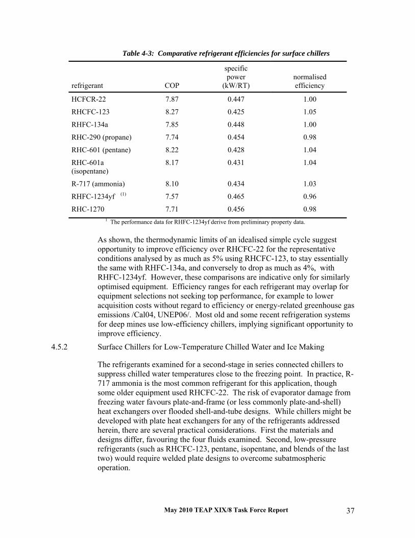
May 2010 TEAP XIX/8 Task Force Report 37
Table 4-3: Comparative refrigerant efficiencies for surface chillers
refrigerant COP
specific power
(kW/RT) normalised efficiency
HCFCR-22 7.87 0.447 1.00
RHCFC-123 8.27 0.425 1.05
RHFC-134a 7.85 0.448 1.00
RHC-290 (propane) 7.74 0.454 0.98
RHC-601 (pentane) 8.22 0.428 1.04
RHC-601a (isopentane)
8.17 0.431 1.04
R-717 (ammonia) 8.10 0.434 1.03
RHFC-1234yf (1) 7.57 0.465 0.96
RHC-1270 7.71 0.456 0.98 1 The performance data for RHFC-1234yf derive from preliminary property data.
As shown, the thermodynamic limits of an idealised simple cycle suggest opportunity to improve efficiency over RHCFC-22 for the representative conditions analysed by as much as 5% using RHCFC-123, to stay essentially the same with RHFC-134a, and conversely to drop as much as 4%, with RHFC-1234yf. However, these comparisons are indicative only for similarly optimised equipment. Efficiency ranges for each refrigerant may overlap for equipment selections not seeking top performance, for example to lower acquisition costs without regard to efficiency or energy-related greenhouse gas emissions /Cal04, UNEP06/. Most old and some recent refrigeration systems for deep mines use low-efficiency chillers, implying significant opportunity to improve efficiency.
4.5.2 Surface Chillers for Low-Temperature Chilled Water and Ice Making
The refrigerants examined for a second-stage in series connected chillers to suppress chilled water temperatures close to the freezing point. In practice, R-717 ammonia is the most common refrigerant for this application, though some older equipment used RHCFC-22. The risk of evaporator damage from freezing water favours plate-and-frame (or less commonly plate-and-shell) heat exchangers over flooded shell-and-tube designs. While chillers might be developed with plate heat exchangers for any of the refrigerants addressed herein, there are several practical considerations. First the materials and designs differ, favouring the four fluids examined. Second, low-pressure refrigerants (such as RHCFC-123, pentane, isopentane, and blends of the last two) would require welded plate designs to overcome subatmospheric operation.

May 2010 TEAP XIX/8 Task Force Report 38
Table 4-4: Comparative refrigerant efficiencies for surface chiller second stage
refrigerant COP
specific power (kW/RT)
normalised efficiency
RHCFC-22
7.00 0.502 1.00
RHC-290 (propane) 6.87 0.512 0.98
R-717 (ammonia) 7.20 0.488 1.03
RHC-1270 (propylene) 6.85 0.513 0.98
Of the candidate refrigerants examined, Table 4-4 indicates a performance advantage for ammonia subject to the same caveats on practical efficiency ranges discussed above. It also offers lower flammability than the two hydrocarbons (propane and propylene). With minimal residual use of RHCFC-22 in this application, its phase-out poses no significant concern. And some of the azeotropic and near-azeotropic blends marketed as RHCFC-22 service fluids would be more suitable, if needed, than in flooded shell-and-tube evaporators.
4.5.3 Underground Chillers
Two significant differences define the third analysis group, namely significantly more extreme heat rejection (condensing) conditions and presumed exclusion of flammable refrigerants. Unlike surface condensing using cooling towers or evaporative condensers, effectively limited by climatic wet bulb temperatures, fresh air is much more limited below 1800 m (5900 ft). The primary supply is a mixture of cooled surface air subsequently warmed by auto-compression and exhaust air warmed and laden with moisture from mine cooling. Of the three conditions examined herein, the underground conditions come closest to the study focus on high-ambient temperatures. Even then, the dry- and wet-bulb temperatures remain similar to widely occurring climatic occurrence and both the average and bubble-point temperatures of condensing refrigerant still lower than in common peak conditions with air-cooled condensing.
Table 4-5 summarises the comparative performance of RHCFC-22 and RHCFC-123 (two HCFCs) with that of RHFC-134a (an HFC). Flammable refrigerants are not examined here based on mine safety practices, precluding use of ammonia, though common for surface chillers, and the more flammable and explosive hydrocarbons. In this context, RHCFC-123 offers a significant advantage predicated on its commercial use as a fire suppressant in contrast to incidents of RHCFC-22 and RHFC-134a explosion and the latter specifically in a mining accident /Hen99, Kra02/, even though non-flammable under normal rating conditions.

May 2010 TEAP XIX/8 Task Force Report 39
Table 4-5: Comparative refrigerant efficiencies for underground chillers
Refrigerant COP
specificpower
(kW/RT)normalisedefficiency
RHCFC-22
4.64 0.758 1.00
RHCFC-123 5.02 0.701 1.08
RHFC-134a 4.57 0.770 0.98
As shown, RHCFC-22 phase-out forces consideration of alternatives including RHCFC-123 and RHFC-134a as well as successor fluids being developed to replace them. Among current options, RHCFC-123 offers higher performance, potentially up to 8%, while RHFC-134a yields lower efficiency. However, RHCFC-22 is no longer commonly used in underground chillers, so the impact is minimal. Also, the older RHCFC-22 chillers still in use are significantly less efficient than newer chillers using other refrigerants, including both HCFC-R123 and RHFC-134a.
Phase-out of RHCFC-123 effectively limits current options to RHFC-134a, though it too is likely to be phased out as addressed above. While RHCFC-123 offers up to 10% higher thermodynamic efficiency than RHFC-134a as indicated in Table 4-5 for underground conditions, there again is overlap in performance for low-efficiency models, especially for older chillers and those retrofit from other refrigerants.
4.6 Not-in-Kind Options Studies of a Brayton air cycle suggest that it could offer both efficiency and cost benefits at depths below 3.5 km (2.2 miles) /del88/, now relevant in light of recent mining below such depths /JMV07/. One of the main unknowns is the effect of ice formation in the expansion turbine, but this concern could be overcome either by drying the compressed air or using modified expansion turbines. Either method is considered costly and could make an air cycle system cost effective only at mining depths greater than 4 km (2.5 miles) if then /del88/.
Air-cycle refrigeration systems using wave-rotor compressors, with reported lower weight and bulk, have been used in two prototype systems installed in gold mines in India and South Africa, /Kha07/, though actual performance data could not be obtained.
Vacuum ice makers, addressed above, offer an opportunity to replace – or at least lessen in light of required pre-cooling of the water used – dependence on refrigerants of concern. Further information on such systems is available from /Jah96/, /Oph07/, /Oph08/, and /IDE09/.

May 2010 TEAP XIX/8 Task Force Report 40
While warranting assessment, use of carbon-dioxide (R-744, CO2) as a heat-transfer fluid (HTF) in a secondary loop is likely to raise significant concerns with the pressures involved, especially so with the hydrostatic heads and adiabatic compression (auto-compressive effect). There likely will be concerns with oxygen displacement and resulting asphyxiation potential should a leak develop underground. No studies were found that examined, and no systems were identified that attempted, this option.
4.7 Changing Criteria Relocation of old equipment from mined-out shafts (in some cases depths) to new mines, shafts, or depths for re-use forces more frequent examination of retirement than is the case for building systems that often continue in operation until no longer repairable. Mining companies already have retrofit or phased out most old equipment using CFCs. The majority of recent deep mine installations have used RHFC-134a (an HFC) and/or R-717 (ammonia) in surface chillers and RHFC-134a in underground chillers.
Several factors that will influence future system selections are changing. First, electricity prices are increasing, significantly so in many deep mine locations. Second and particularly in some developing countries, inadequate power supplies are forcing demand limits or even curtailments to make electricity more available for other markets, such as urban and manufacturing uses. Both factors are forcing attention to improved efficiency and replacement of older, less efficient equipment.
Third, mines are going deeper to reach previously untapped or previously less economic minerals. Cooling loads therefore are increasing from increased geothermal, auto-compression, and machine loads. They force both system innovation, including lowered supply and raised return temperatures for chilled water, and use of both ice slurry and hard ice systems. Increased depth also heightens flammability concerns, with more limited egress, and to reliability, with increasing dependence as critical for both life safety and productivity.
Additionally, mining firms are under intense pressure to be perceived as socially responsible to avoid mandates and to attract investment, hence they are seeking to be and to be seen as environmentally responsible and innovative. Collaborative efforts to assess system options and safety measures are common.
The consequence for mine refrigeration systems is keen awareness of environmental restrictions on refrigerants and willingness to examine more efficient, long-term alternatives.

May 2010 TEAP XIX/8 Task Force Report 41
4.8 Concluding Remarks As detailed herein, deep mine systems are not as vulnerable to high-ambient climatic conditions as other applications addressed in this report. CFC use is very limited and replacement is progressing. HCFC and especially RHCFC-22 dependence is comparatively low and again being addressed. Unlike instances where economic limits may hinder transition to new, more acceptable technologies and retard development for countries in extreme climates, nearly all deep mines are capitalised and run by multi-national firms that address equipment costs as critical investments in an already capital- and skill-intensive industry. Rather than developing countries being at a technological disadvantage in mining, some Article 5 countries – and South Africa in particular – are world leaders in the technologies involved and able to export the requisite technologies.
4.9 References
/Bai01/ M. Bailey-McEwan, “The Role of Water Chilling Machines in Optimising Performance of Existing Mine Cooling Systems,” chapter 108, Proceedings of the 7th International Mine Ventilation Congress, Kraków, Poland, 2001.06
/Blu98/ S. J. Bluhm, M. Biffi, and R. B. Wilson, “Optimised cooling systems for mining at extreme depths,” Proceedings CIM/CMMI/MIGA Conference, Canadian Institute of Mining and Metallurgy, Montréal, QU, Canada, 1998 ◊
/Bra00/ D. J. Brake and R. Fulker, “The Ventilation and Refrigeration Design for Australia’s Deepest and Hottest Underground Operation – the Enterprise Mine,” MassMin 2000 Proceedings, Australasian Institute of Mining and Metallurgy (AuslMM), 611-621, 2000
/Bra01a/ D. J. Brake, “The Application of Refrigeration in Mechanised Mines,” AusIMM Proceedings, Australasian Institute of Mining and Metallurgy (AuslMM), 306(1):1-10, 2001
/Bra01b/ D. J. Brake, “Key Engineering Considerations in the Specification and Selection of Mine Refrigeration Plants,” AusIMM Proceedings, Australasian Institute of Mining and Metallurgy (AuslMM), 306(2):1-16, 2001
/Bro09/ J. S. Brown, P. A. Domanski, and E. W. Lemmon, CYCLE_D: NIST Vapor-Compression Design Program (version 4.0), Standard Reference Database 49, National Institute of Standards and Technology (NIST), Gaithersburg, MD, USA, 2009
/Bro10/ J. S. Brown, C. Zilio, and A. Cavallini, “Thermodynamic properties of eight fluorinated olefins,” International Journal of Refrigeration, 33(2):235-241, 2010.03
/Cal99/ J. M. Calm, D. J. Wuebbles, and A. K. Jain, “Impacts on Global Ozone and Climate from Use and Emission of 2,2-Dichloro-1,1,1-trifluoroethane (HCFC-123),” Journal of Climatic Change, 42(2):439-474, 1999.06

May 2010 TEAP XIX/8 Task Force Report 42
/Cal04/ J. M. Calm, “Comparative Efficiencies and Implications for Greenhouse Gas Emissions of Chiller Refrigerants,” Fourth International Symposium on Non-CO2 Greenhouse Gases (NCGG-4, Utrecht, The Netherlands, 2005.07.04-06), Vereniging van Milieukundigen (VVM) [Netherlands Association for Environmental Professionals], Den Bosch; The Netherlands; Millpress Science Publishers, Rotterdam, The Netherlands; 671-680, 2005.07
/Cal06/ J. M. Calm, “Environmental and Performance Studies of R-123 as a Chiller Refrigerant – Resulting Recommendations for Environmental Protection,” paper R147, Proceedings of the 11th International Refrigeration and Air-Conditioning Conference, Purdue University, West Lafayette, IN, USA, 2006.07
/Cal07/ J. M. Calm and G. C. Hourahan, “Refrigerant Data Update,” Heating/Piping/Air Conditioning Engineering, 79(1):50-64, January 2007
/Cal08/ J. M. Calm, “The Next Generation of Refrigerants – Historical Review, Considerations, and Outlook,” International Journal of Refrigeration, 31(7):1123-1133, 2008.11
/del88/ D. del Castillo, “Air Cycle Refrigeration System for Cooling Deep Mines,” International Journal of Refrigeration, 11(2):87-91, 1988.03
/Eco07/ “Deep Mine Achieves High Efficiency, Ecolibrium, 6(5):18-20, 2007.06 /EOS10/ R-1234yf (preliminary Helmholtz equation of state derived from limited data),
unpublished and undocumented, 2010.01.08 /Hag91/ M. Hager and T. Kamper, “The Hydraulic Transport of Ice for Mine-Cooling,”
Powder Handling and Processing, 3(4):317-325, 1991 ◊ /Hen99/ M. P. Hendriks, TauTona Mine Turbo Engineering Machine 1A Incident: Results of
the Investigation of the Explosion in Chiller 1A Compressor, AngloGold Limited (now AngloGold Ashanti Limited), Marshalltown, GT, South Africa, 1999.11.01
/How97/ M. J. Howes and C. A. Nixon, “Development of Procedures for Safe Working in Hot Conditions,” Proceedings of the 6th International Mine Ventilation Congress, (Pittsburgh, PA, USA), Society for Mining, Metallurgy, and Exploration (SME), Littleton, CO, USA, pp. 191-198, 1997.05
/IPCC07/ Intergovernmental Panel on Climate Change (IPCC), Climate Change 2007: The Physical Science Basis – Contribution of Working Group I to the Fourth Assessment Report, World Meteorological Organization (WMO) and United Nations Environment Programme (UNEP), IPCC Secretariat, Geneva, Switzerland, 2007
/Jah96/ E. Jahn, D. Lausen, and J. Paul, “Cooling of Mines with Vacuum Ice,” Proceedings of the FRIGAIR ’96 Conference, Johannesburg, South Africa, 1996.03
/JMV07/ “Giving Confidence to Go Down to 5 km Underground,” Journal of the Mine Ventilation Society of South Africa, p. 120, 2006.10-12
/Kha05/ A. A. Kharazi, P. Akbari, and N. Müller, “R718 Refrigeration Cycle Using Three Port Condensing Wave Rotor, Journal of Engineering for Gas Turbines and Power, 127:539-544, 2005.07
/Kon10/ K. Kontomaris and T. J. Leck TJ, Low GWP Refrigerants Centrifugal Chillers, unpublished presentation (ASHRAE Annual Meeting, Louisville, KY, USA, DuPont, Fluoroproducts, Wilmington, DE, USA, 2009.06.24
/KP97/ Kyoto Protocol to the United Nations Framework Convention on Climate Change, United Nations (UN), New York, NY, USA, 1997
May 2010 TEAP XIX/8 Task Force Report 43
/Kra02/ A. P. Kramers, M. Butterworth, M. Biffi, F. J. Van Zyl, J. P. Meyer, N. Denys, R. Ramsden, “An Investigation into the Conditions under which HFC134a May Become Flammable," Final Report on Project GAP 806 (EC 02-0062), Safety in Mines Research Advisory Committee (SIMRAC), Braamfontein, South Africa, 2002.01
/Lem07/ E. W. Lemmon, M. L. Huber, and M. O. McLinden, NIST Reference Fluid Thermodynamic and Transport Properties – REFPROP (version 8.0), Standard Reference Database 23, NIST, Gaithersburg, MD, USA, 2007.04 with 2010.04.02 patch
/Mac99/ I. L. Maclaine-cross, “Replacement Refrigerants for Water Chillers,” Proceedings Seminar on ODS Phaseout: Solutions for the Refrigeration (Kuta, Bali, Indonesia, 1999.05.05-07), Bandung Institute of Technology (ITB), Indonesia, 50-55, 1999.05
/Mac02/ I. L. Maclaine-cross, “Replacement Refrigerants for Centrifugal Chillers,” AIRAH Natural Refrigerants Conference (Melbourne, VIC, Australia), Australian Institute of Refrigeration, Air Conditioning and Heating (AIRAH), Melbourne, VIC, Australia, 2002
/Mar07/ J. R. Marks, “Mine Air Conditioning and Ventilation,” ASHRAE Handbook: HVAC Applications, American Society of Heating, Refrigerating, and Air-Conditioning Engineers (ASHRAE), Atlanta, GA, USA, chapter 27, 1987
/McP93/ M. J. McPherson, “Refrigeration Plant and Mine Air Conditioning Systems,” chapter 18, Subsurface Ventilation and Environmental Engineering, ISBN 0412353008, Chapman & Hall, London, UK, 1993.04
/Mol04/ M. J. Molina et al., “Science Symposium Summary, Challenges and Perspectives - Ozone Layer Protection,” Prague, Czech Republic, 2004.11.19
/MP87/ Montreal Protocol on Substances That Deplete the Ozone Layer, United Nations (UN), New York, NY, USA, 1987 with subsequent amendments through 2007
/MT07/ Modular Underground Air Cooling Unit (ACU), bulletin 300709, M-Tech Industrial (Pty) Ltd, Potchefsroom, RSA, 2007 (developed in conjunction with North-West University (formerly Potchefsroom University)
/MVS06/ “Giving Confidence to Go Down to 5 km,” Journal of the Mine Ventilation Society of South Africa, 2006(10-12):120, 2006
/Oph07/ A. Ophir, Energy Efficient Vacuum Ice-Maker Using Water as Refrigerant for Thermal Energy Storage and Heat Pumps, IDE Technologies, Kadima, Israel, 2007
/Oph08/ A. Ophir, “Mechanical Heat Pumps Using Water as Refrigerant for Ice Production and Air Conditioning,” presentation, IDEA 99th Annual Convention (Orlando, Florida, USA), International District Energy Association, Westborough, MA, USA, 2008
/Pau96/ J. Paul, “Non-Conventional Cooling Systems for Mines," Proceedings of the FRIGAIR ’96 Conference, Johannesburg, South Africa, 1996.03 ◊
/Pic97/ A. J. Pickering and M. A. Tuck, “Heat: Sources, Evaluation, Determination Of Heat Stress And Heat Stress Treatment,” Heat and Noise in Underground Mining Symposium, Nottingham, UK, 1997.04
/Ram01/ R. Ramsden, T. J. Sheer, and M. D. Butterworth, “Design and Simulation of Ultra-Deep Mine Cooling Systems,” chapter 106, Proceedings of the 7th International Mine Ventilation Congress, Kraków, Poland, June 2001

May 2010 TEAP XIX/8 Task Force Report 44
/Ram07/ R. Ramsden, A. R. Branch, and R. Wilson, “Factors influencing the choice of cooling and refrigeration systems for mines,” Journal of the Mine Ventilation Society of South Africa, 60(3):92-98, 2007.07-09
/Rob09/ A. Robbins, unpublished data, AngloGold Ashanti, Mponeng Mine, Vaal Reef, South Africa, 2009.09.02
/Ros08/ L. Rostoll, “Deep-Level Mining – As Mines Go Deeper, Spotlight’s Falling Once More on Ice Technology,” Mining Weekly, 2008.03.08
/Sea03/ T. P. Seager and T. L. Theis, “A Thermodynamic Basis for Evaluating Environmental Policy Trade-Offs,” Clean Technologies and Environmental Policy, 4:217–226, 2003
/She01/ T. J. Sheer, M. D. Butterworth, and R. Ramsden, “Ice as a Coolant for Deep Mines,” chapter 52, Proceedings of the 7th International Mine Ventilation Congress, Research and Development Center for Electrical Engineering and Automation in Mining, Kraków, Poland, June 2001
/Tad06/ A. Tadros, J. W. Clark, I. L. Maclaine-cross, and E. Leonardi, “Replacing Fluorocarbons with Hydrocarbon Mixtures in Centrifugal Water Chillers,” Natural Working Fluids (proceedings of the 7th IIR - Gustav Lorentzen Conference, Trondheim, Norway, 2006.05.28-31), International Institute of Refrigeration (IIR), Paris, France, 395-398, 2006
/UNEP06/ Report of the Refrigeration, Air-Conditioning and Heat Pumps Technical Options Committee (RTOC) – 2006 Assessment, IBSN 978-92-807-2822-4, United Nations Environment Programme (UNEP) Ozone Secretariat, Nairobi, Kenya, January 2007
/WMO06/ Scientific Assessment of Ozone Depletion: 2006, World Meteorological Organization (WMO), Global Ozone Research and Monitoring Project, Geneva, Switzerland; United Nations Environment Program (UNEP), Nairobi, Kenya; National Oceanic and Atmospheric Administration (NOAA), Washington, DC, USA; National Aeronautics and Space Administration (NASA), Washington, DC, USA; and the European Commission, Research Directorate General, Brussels, Belgium; March 2007
/Wue09/ D. J. Wuebbles and K. O. Patten, “Three-Dimensional Modeling of HCFC-123 in the Atmosphere – Assessing Its Potential Environmental Impacts and Rationale for Continued Use,” Environmental Science & Technology, 2009, 43(9):3208-3213, 2009
/IDE09/ IDE's Vacuum Ice Maker (VIM) for Mine Cooling, IDE Technologies Limited, Kadima, Israel, 2009.04.27
/Xst05/ “Mount Isa Mines Now Generating Emission Free Electricity,” Mine to Market, Xstrata plc, Mount Isa, Queensland, Australia, 52:9, 2005.07
/Xst09/ Mount Isa Mines, Xstrata plc, London, UK, 2009