Montageanleitung Installation Instruction Instructions de Montage · Installation Instruction 90 mm...
36
Montageanleitung 90 mm BI LED Modul Installation Instruction 90 mm BI LED Module Instructions de Montage 90 mm BI LED Module Monteringsanvisning 90 mm BI LED Modul Montagehandleiding 90 mm BI LED Module Instrucciones de Montaje 90 mm BI Módulo LED Instruzioni di Montaggio 90 mm BI LED Module Asennusohje 90 mm BI LED Module
Transcript of Montageanleitung Installation Instruction Instructions de Montage · Installation Instruction 90 mm...

Montageanleitung90 mm BI LED Modul
Installation Instruction90 mm BI LED Module
Instructions de Montage90 mm BI LED Module
Monteringsanvisning90 mm BI LED Modul
Montagehandleiding90 mm BI LED Module
Instrucciones de Montaje90 mm BI Módulo LED
Instruzioni di Montaggio90 mm BI LED Module
Asennusohje90 mm BI LED Module

2
Technische Änderungen vorbehalten DE
Con riserva di modifiche tecniche IT
Vi reserverar oss för tekniska ändringar SV
Subject to alteration without notice EN
Oikeus teknisiin muutoksiin pidätetään FI
Technische wijzigingen voorbehouden NL
Sous réserve de modifications techniques FR
Reservadas modificaciones técnicas ES

3
LegendaPiirroksen selitys
ZeichenerklärungExplanation of symbolsExplication des symboles
SymbolförklaringLegendaAclaración de símbolos
DE
EN
FR
SV
NL
ES
IT
FI
Richtig
Correct
Correct
Goed
Correcto
Giusto
Oikein
Rätt
DE
EN
FR
SV
NL
ES
IT
FI
Falsch
Incorrect
Incorrect
Fout
Erróneo
Sbagliato
Väärin
Fel
DE
EN
FR
SV
NL
ES
IT
FI
Positionspfeil
Location/Position Arrow
Flèche de Position
Lokatie/Positie pijl
Flecha de posición
Freccia di posizione
Paikannusnuoli
Positionpil
DE
EN
FR
SV
NL
ES
IT
FI
Bewegungspfeil
Movement Arrow
Flèche indiquant sens du vouvement
Richtingspijl
Flecha de moviemiento
Freccia di movimentov
Liikesuuntanuoli
Rörelsepil
DE
EN
FR
SV
NL
ES
IT
FI
Achtung
Warning
Attention
Let op
Atención
Attenzione
Huomio
Varning

4
LieferumfangKit IncludesFourniture
LeveransomfattningInhoud SetVolumen del Suministro
Dotazione di FornituraOsaluettelo
3x
3x
1AL 010 820- 02X
1LL 010 820- 03X

5
TillbehörToebehorenAccessorios
ZubehörAccessoriesAccessories
AccessoriLisätarvikkeet
6NM 007 282- 221 (12V)
6NM 008 299-501 (24V)
8HG 138 619- 007
8JA 746 184- 032
8KW 744 837- 002
9GD 746 185- 002
8HG 138 620- 007
9AH 169 580- 011 9AH 185 978- 011

6
Torx 20
SW 10
3,5 mm5 mm6,5 mm
14 mm16 mm17 mm24 mm
Benötigte MontagewerkzeugeInstallation tools requiredOutillage de montage requis
Nödvändiga monteringsverktygBenodigde montagewerktuigenHerramientas de montaje necesarias
Attrezzi necessari per il montaggioTarvittavat asennustyökalut

7
10 mm *
20 mm *50.4
mm
176.
6 m
m18
2.3
mm
Ø 110 mmØ 90 mm 10 mm *
* 32, 33
20 mm *
20 mm
390
mm
Ø 90 mm143.2 mm
> 69°C
MontageMountingMontage Général
MonteringMontageMontaje
MontaggioAsennus

8
CHECK SIZE
Print 100%Check with Rulers
before use.
85 ± 0.2 mm
Ø 6.5 mm (6x)
51 m
m
85 ±
0.2
mm
33 m
m
8 m
m
104 mm
50 mm
1:1
Ø 16 mm + 0.1 mm (4x)
9AH 169 580- 011

9
85 ± 0.2 mm
85 ±
0.2
mm
Ø 14 mm + 0.1 mm (4x)
CHECK SIZE
Print 100%Check with Rulers
before use.
1:1

10
42.5
mm
6.5
mm
1:1
85 ±
0.2
mm
Ø 6.5 mm
38 mm
Print 100%Check with Rulers
before use.
85 ± 0.2 mm
132 mm
CHECK SIZE
Ø 24 mm + 0.1 mm (4x)
9AH 185 978- 011

11
85 ±
0.2
mm
CHECK SIZE
Print 100%Check with Rulers
before use.
Ø 17 mm + 0.1 mm (4x)
85 ± 0.2 mm
1:1

12
Ø 3.5 mm
5 mm
13 m
m
CHECK SIZE
Print 100%Check with Rulers
before use.
Ø 2
4 m
m
1:1

13
14 - 18
19 - 23

14
CHECK SIZE
Print 100%Check with Rulers
before use.
85 ± 0.2 mm
Ø 6,5 mm
51 m
m
85 ±
0.2
mm
Ø 16 mm
104 mm
50 mm CHECK SIZEPrint 100%
Check with Rulers
before use.
85 ± 0.2 mm
Ø 6,5 mm
51 m
m85
± 0
.2 m
m
Ø 14 mm
104 mm
50 mm
Ø 16 mm
Ø 6,5mm
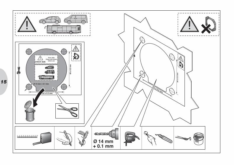
15
85 ±
0.2
mm
Ø 14 mm + 0.1 mm
CHECK SIZE
Print 100%Check with Rulers
before use.
85 ± 0.2 mm
85 ± 0.2 mm
85 ±
0.2
mm
Ø 14 mm+ 0.1 mm

16
SW 10
Ø 16 mm

17
CLICK
CLICK
1
2
1
1
1
1
Torx 20
max
. 19,
6 m
m
24
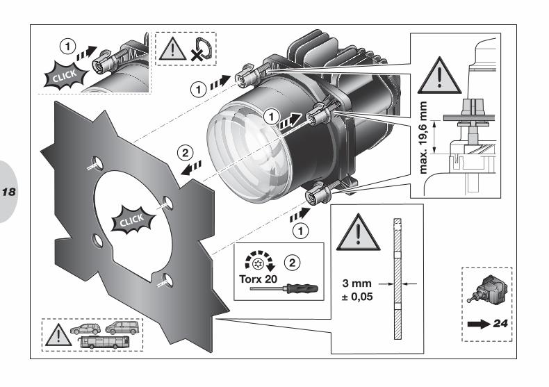
18
3 mm± 0,05
CLICK
CLICK
1
2
2
1
1
1
Torx 20
max
. 19,
6 m
m
24

1942
.5 m
m
6.5
mm
85 ±
0.2
mm
Ø 6.5 mm
38 mm
Print 100%Check with Rulers
before use.
85 ± 0.2 mm
132 mm
CHECK SIZE
Ø 24 mm + 0.1 mm (4x)
42.5
mm
6.5
mm
85 ±
0.2
mm
Ø 6.5 mm38 mm
Print 100%
Check with Rulers
before use.
85 ± 0.2 mm132 mm
CHECK SIZEØ 24 mm + 0.1 mm (4x)
Ø 24 mm
Ø 6,5mm

20
85 ±
0.2
mm
CHECK SIZE
Print 100%Check with Rulers
before use.
Ø 17 mm + 0.1 mm
85 ± 0.2 mm
85 ±
0.2
mm
85 ± 0.2 mm
Ø 17 mm

21
SW 10
Ø 24 mm

22
CLICK
CLICK
1
2
2Torx 20
max
. 19,
6 m
m
3
33
1
1
1
24

23
3 mm± 0,05
CLICK
CLICK
1
2
2
3
33
Torx 20
max
. 19,
6 m
m
1
1
1
24

24Ø 3,5 mm
5 mm
13 m
m
CHECK SIZE
Print 100%Check with Rulers
before use.
Ø 2
4 m
m
85 ± 0.2 mm
Ø 3,5 mm
5 mm
13 m
m
CHECK SIZEPrint 100%
Check with Rulers
before use.
Ø 2
4 m
m
Ø 3,5 mmØ 5 mmØ 24 mm

25
1
2
3
1
2
3
8HG 138 620- 007 8HG 138 619- 007

26
44 mm
44 mm
CLICK

27
45º 45º
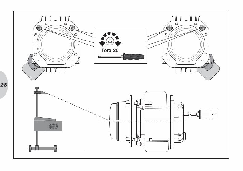
28
Torx 20

29 32
1
1 =
2 =
3 =
Elektrischer AnschlussElectrical connectionBranchement électrique
Elektrisk anslutningElektrische aansluitingConexión eléctrica
Collegamento elettricoOsaluettelo
30
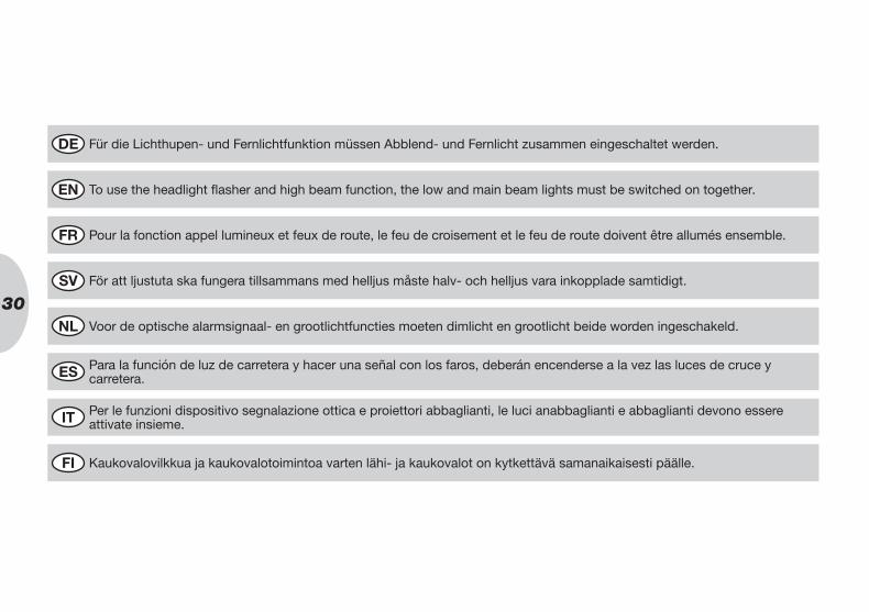
Für die Lichthupen- und Fernlichtfunktion müssen Abblend- und Fernlicht zusammen eingeschaltet werden.DE
Per le funzioni dispositivo segnalazione ottica e proiettori abbaglianti, le luci anabbaglianti e abbaglianti devono essere attivate insieme.
IT
För att ljustuta ska fungera tillsammans med helljus måste halv- och helljus vara inkopplade samtidigt.SV
To use the headlight flasher and high beam function, the low and main beam lights must be switched on together.EN
Kaukovalovilkkua ja kaukovalotoimintoa varten lähi- ja kaukovalot on kytkettävä samanaikaisesti päälle.FI
Voor de optische alarmsignaal- en grootlichtfuncties moeten dimlicht en grootlicht beide worden ingeschakeld.NL
Pour la fonction appel lumineux et feux de route, le feu de croisement et le feu de route doivent être allumés ensemble.FR
Para la función de luz de carretera y hacer una señal con los faros, deberán encenderse a la vez las luces de cruce y carretera.
ES

31
Informationstext 32DE
Informazioni 33IT
Informationstext 32SV
Information Text 32EN
Ohjetekstit 33FI
Informatie tekst 32NL
Texte d’information 32FR
Texto informativo 32ES

32
DEUTSCHDE
ENGLISHEN
Low Beam: max. 35 WHigh Beam: max. 35 WFuse Low Beam: 5 AFuse High Beam: 5 AOperating Voltage: 9-32 VMax. Operating temperature range: + 50 ºC
The legally required failure indicator stipu-lated in the ECE R48 regulation for the LED headlights is to be mounted in the vehicle. Take the necessary precautions in order that these regulations are met.
* The gauge must be kept circulating around the module.
Halvljus: max. 35 WHelljusstrålkastare: max. 35 WSäkring Halvljus: 5 ASäkring Helljusstrålkastare: 5 ADriftspänning: 9-32 VMax. Driftstemperaturområde: + 50 ºC
Den felkontroll som lagen kräver för området ECE R48 för LED-strålkastare ska säkerställas i fordonet genom lämpliga åtgärder.
* Värdet måste hållas konstant för hela modulen.
Luz de cruce: max. 35 WLuz antiniebla trasera: max. 35 WFusible Luz de cruce: 5 AFusible Luz antiniebla trasera: 5 ATensión de régimen: 9-32 VGama de temperaturas de trabajo máx.: + 50 ºC
El control de fallos que exige la ley dentro del ámbito de aplicación de la normativa ECE R48 para los faros de LED queda ga-rantizado en el vehículo con las medidas adecuadas.
* Las dimensiones deben ajustarse al perímetro del módulo.
Abblendlicht: max. 35 WFernlicht: max. 35 WSicherung Abblendlicht: 5ASicherung Fernlicht: 5ABetriebsspannung: 9-32 VMax. Betriebstemperatur: + 50 ºC
Die im Geltungsbereich der ECE R48 ge setzlich geforderte Ausfallkontrolle für den LED Scheinwerfer ist im Fahrzeug durch geeignete Maßnahmen sicher-zustellen.
* Das Maß muss umlaufend um das Modul eingehalten werden.
Feux de croisement: max. 35 WFeu de route: max. 35 WFusible Feux de croisement: 5 AFusible Feu de route: 5 ATension de service: 9-32 VMax. Plage de températures: + 50 ºC
La norme ECE R48 impose le montage d’un témoin de panne dans le véhicule lors de l’installation de projecteurs à DEL. Prendre les dispositions nécessaires pour satisfaire à la norme.
* La dimension doit correspondre à la périphérie du module.
Dimlicht: max. 35 WGrootlicht: max. 35 WZekering Dimlicht: 5 AZekering Grootlicht: 5 ABedrijfsspanning: 9-32 VMax. Temperatuurbereik: + 50 ºC
De in het toepassingsbereik van de ECE R48 wettelijk vereiste uitvalcontrole voor de LED koplamp dient in het voertuig door de juiste maatregelen te worden gewaar-borgd.
* De maat moet rondom de module worden aangehouden.
FRANÇAISFR
SVENSKASV
NEDERLANDSNL
ESPAÑOLES

33
Lähivalot: enint. 35 WAsennusohjeita: enint. 35 WSulake Lähivalot: 5 ASulake Asennusohjeita: 5 AKäyttöjännite: 9-32 VToimintalämpötila: + 50 ºC
ECE R48 -standardin voimassaoloalueella lakisääteinen LED-valonheittimien toimin-tahäiriön valvonta on varmistettava ajone-uvoissa sopivien toimenpiteiden avulla.
* Arvoa on noudatettava moduulin ympärillä.
Proiettore anabbagliante: max. 35 WLuce abbagliante: max. 35 WFusibile Proiettore anabbagliante: 5 AFusibile Luce abbagliante: 5 ATensione di funzionamento: 9-32 VCampo della temperatura di funzionamento max.: + 50 ºC
Il controllo dei guasti prescritto per legge nell’ambito di applicazione della norma ECE R48 per il fanale a LED deve essere garantito sul veicolo mediante adeguati provvedimenti.
* La misura deve essere rispettata sull’intero perimetro del modulo.
ITALIANOIT
SUOMIFI

34
Beleuchtungsanlage auf einwandfreie Funktion hin prüfenDE
Controllare la perfetta funzionalità dell’impianto di illuminazioneIT
Kontrollera att ljussystemet fungerar felfrittSV
Check that the lighting system is working perfectlyEN
Tarkasta valaistusjärjestelmän toimintaFI
Controleer of de verlichting goed functioneertNL
Contrôler le bon fonctionnement de l’installation d’éclairageFR
Comprobar que el sistema de iluminación funciona impecablementeES

35
Bei Fragen oder Einbauproblemen, rufen Sie bitte den HELLA Kundendienst, Großhändler an oder wenden Sie sich an Ihre Werkstatt.
DE
Per qualsiasi domanda o problemi di montaggio si prega di contattare il servizio assistenza o il proprio grossista HELLA op-pure di rivolgersi alla propria officina.
IT
Vid frågor eller monteringsproblem, kontakta Hellas kundtjänst, återförsäljaren eller din verkstad.SV
If you have questions or installation problems, please call the HELLA Service, wholesaler, or turn to your garage.EN
Jos sinulla on kysymyksiä tai asennusongelmia, soita HELLA-asiakaspalvelulle tai tukkuliikkeelle tai käänny korjaamon puoleen.
FI
In geval van vragen of montageproblemen verzoeken wij u contact met de HELLA-klantenservice, de groothandel of uw dealer op te nemen.
NL
Pour toutes questions ou problèmes de montage, merci de contacter le service après-vente HELLA, votre distributeur ou votre garage.
FR
En caso de dudas o problemas de montaje, por favor, llame al Servicio postventa de Hella o al mayorista, o bien diríjase a su taller.
ES

© Hella KGaA Hueck & Co., D-59552 Lippstadt · 460 942-02 · 02/12 · Printed in Germany