Montage- und Bedienungsanleitung Installation and … functions of the VDO Ocean Line anemometer...
23
VDO Kienzle Vertrieb und Service GmbH Montage- und Bedienungsanleitung Installation and Operating Instructions Wind
Transcript of Montage- und Bedienungsanleitung Installation and … functions of the VDO Ocean Line anemometer...

VDO Kienzle Vertrieb und Service GmbH
Montage- und BedienungsanleitungInstallation and Operating Instructions
Wind
olwind~1.qxd 09.11.99 08:34 Seite 1

Installation and Operating InstructionsPage 22 - 40
21
olwind_e.qxd 21.06.99 13:35 Seite 21

22
olwind_e.qxd 21.06.99 13:35 Seite 22
Table of contents
Preface . . . . . . . . . . . . . . . . . . . . . . . . . . . . . . . . . . . . . . . . . . 24Safety instructions . . . . . . . . . . . . . . . . . . . . . . . . . . . . . . . . 25
for installation . . . . . . . . . . . . . . . . . . . . . . . . . . . . . . . . . 25for maintenance . . . . . . . . . . . . . . . . . . . . . . . . . . . . . . . 26
The VDO Ocean Line Wind . . . . . . . . . . . . . . . . . . . . . . . . . . 27Components of the system . . . . . . . . . . . . . . . . . . . . . . . . . . . 28Accessories . . . . . . . . . . . . . . . . . . . . . . . . . . . . . . . . . . . . . . . 28Spare parts . . . . . . . . . . . . . . . . . . . . . . . . . . . . . . . . . . . . . . . 28
Display functions of the VDO Ocean Line Windanemometer system . . . . . . . . . . . . . . . . . . . . . . . . . . . . . . . 29
Maintenance of the VDO Ocean Line Wind . . . . . . . . . . . . . 30
Troubleshooting . . . . . . . . . . . . . . . . . . . . . . . . . . . . . . . . . . 30
Installing the VDO Ocean Line Wind . . . . . . . . . . . . . . . . . . 31Installing the indicating instrument . . . . . . . . . . . . . . . . . . . . . 31Installing the wind sensor . . . . . . . . . . . . . . . . . . . . . . . . . . . . 33
Electrical installation. . . . . . . . . . . . . . . . . . . . . . . . . . . . . . . 36Setting the instrument for wind speed indication. . . . . . . . . . . 36System power supply . . . . . . . . . . . . . . . . . . . . . . . . . . . . . . . 37Connecting an analog wind speed indicating instrument . . . . 38Connecting a secondary indicating instrument . . . . . . . . . . . . 40Key for circuit diagram. . . . . . . . . . . . . . . . . . . . . . . . . . . . . . . 41Cable lengths. . . . . . . . . . . . . . . . . . . . . . . . . . . . . . . . . . . . . . 41
Technical data . . . . . . . . . . . . . . . . . . . . . . . . . . . . . . . . . . . . 41
23
CONTENTS
olwind_e.qxd 21.06.99 13:35 Seite 23

24
PREFACE
Preface
Thank you for selecting an instrument from the VDO Marine programrange; a high-quality, state-of-the-art product providing invaluableassistance and safety at sea. Our advanced production methods andthe conformance of our products to the relevant quality assurancestandards ensure that our products are dispatched in excellentcondition.
Please take the time to study this manual carefully. It will tell you all youneed to know about the functions of your VDO anemometer system andensure that it is straightforward and safe to use.
If you have any further queries or problems, please do not hesitate tocontact your VDO Kienzle agent who will be pleased to help you.
Yours sincerelyVDO Kienzle Vertrieb und Service GmbH
© Copyright by VDO Kienzle Vertrieb und Service GmbH 1999All rights reserved
Manual should always be kept on board!
olwind_e.qxd 21.06.99 13:35 Seite 24

Safety instructions
Please respect all instructions in this manual.
Please pay particular attention to text marked withthis symbol, which indicates an important aspect ofsystem operation and safety.
Using the compass system does not relieve you of the responsibility foryour ship, and requires good seamanship.Always rely on your nautical experience for the interpretation of theindicated values.
Safety Instructions for installation:The anemometer system should be installed by your shipyard or by aspecialist.Adequate working clothes should be worn if you install it yourself. Avoidloose clothing and use a hair net if your hair is long. Clothing and hairmay be caught in moving parts.Remove all metallic or electrically conducting jewelry, such as chains,bracelets, rings, etc. when working on the on-board electrical system.Disconnect the minus polarity of the battery before starting your work toprevent the risk of a short-circuit. Short-circuits can cause harness fires,battery explosions and damages of other electronic memory systems.Please note that all volatile electronic memories will lose their contents,and will have to be re-programmed if you disconnect the battery.VDO instruments are not equipped with volatile memories.
Risk of explosion! Run the engine blower for a certain time beforestarting work in a gasoline engine compartment.
Check for sufficient clearance behind the mounting hole when selectingthe location for the indicating instrument. Pre-drill the hole and finish withhole or keyhole saw (respect the safety instructions of the toolmanufacturer).
25
SAFETY INSTRUCTIONS
olwind_e.qxd 21.06.99 13:35 Seite 25

If you must work without disconnecting the power supply, insulated toolsshould be used.
The electrical outputs of the anemometer system indicating instrumentand the cables connected to them must be protected against directcontact or damage. This means that the cables must have a sufficientinsulation resistance or voltage rating, and that touching the contactpoints is prevented.
Adequate measures are taken to ensure that electrically conductingparts of the connected consumers are protected against direct contact.The use of non-insulated wires and contacts is strictly forbidden.
Safety Instructions for maintenanceAnemometer system components can only be repaired by specialistsauthorized by VDO Kienzle. The VDO LOGIC anemometer systemfulfills the applicable safety regulations.
Note: Capacitors in the unit can retain their charge, even if the unit isseparated from its power supply.
Check that replacement fuses are of the indicated type and currentrating. The use of temporarily repaired fuses or jumpering the fuseholder is strictly forbidden.
26
SAFETY INSTRUCTIONS
olwind_e.qxd 21.06.99 13:35 Seite 26
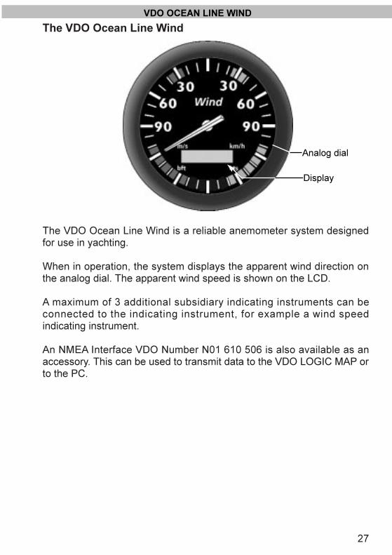
The VDO Ocean Line Wind
The VDO Ocean Line Wind is a reliable anemometer system designedfor use in yachting.
When in operation, the system displays the apparent wind direction onthe analog dial. The apparent wind speed is shown on the LCD.
A maximum of 3 additional subsidiary indicating instruments can beconnected to the indicating instrument, for example a wind speedindicating instrument.
An NMEA Interface VDO Number N01 610 506 is also available as anaccessory. This can be used to transmit data to the VDO LOGIC MAP orto the PC.
27
VDO OCEAN LINE WIND
Display
Analog dial
olwind_e.qxd 21.06.99 13:35 Seite 27
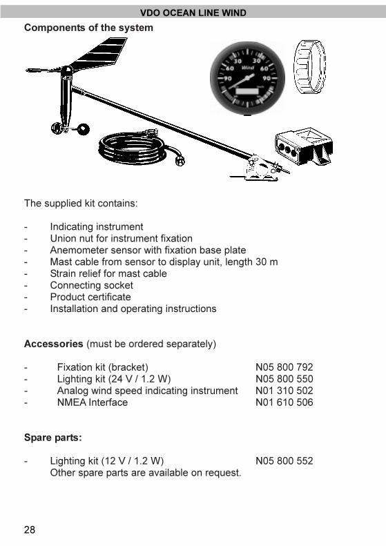
Components of the system
The supplied kit contains:
- Indicating instrument- Union nut for instrument fixation- Anemometer sensor with fixation base plate- Mast cable from sensor to display unit, length 30 m- Strain relief for mast cable- Connecting socket- Product certificate- Installation and operating instructions
Accessories (must be ordered separately)
- Fixation kit (bracket) N05 800 792- Lighting kit (24 V / 1.2 W) N05 800 550- Analog wind speed indicating instrument N01 310 502- NMEA Interface N01 610 506
Spare parts:
- Lighting kit (12 V / 1.2 W) N05 800 552Other spare parts are available on request.
28
VDO OCEAN LINE WIND
olwind_e.qxd 21.06.99 13:35 Seite 28

Display functions of the VDO Ocean Line anemometersystem
1. Apparent wind directionThe needle on the indicating instrument indicates the apparentwind direction. The colored area on the dial marks the optimumwind angle at which the best possible speed can be expected,either against or with the wind.
2. Apparent wind speedThe wind speed is shown on the LCD in the unit specified duringsetup (m/s, km/h, bft or kts). The selected unit will be marked onthe display with a small angle (in the above illustration, forexample, the wind speed wil l be displayed in knots). Onconnection to the boat�s supply system, the unit in which the windspeed should be displayed in the LCD should be set (see theInstallation section).
29
DISPLAY FUNCTIONS
Apparentwind speed
Angle giving unit for windspeed
Apparent wind direction
olwind_e.qxd 21.06.99 13:35 Seite 29

Maintenance of the VDO Ocean Line Wind
The indicating instrument is maintenance-free. Clean the indicatinginstrument with a damp, non-fuzzing or anti-static cloth. Do not usecleaning detergents.
The wind sensor does not need any maintenance. Do not oil the sensorbearings, as the oil may gum and attract dirt particles.
The electrical contacts of the socket at the mast footing should becleaned once per season. Oxidized contacts can lead to systemfailures.
Troubleshooting
Fault Cause/ Remedy:
- VDO Ocean Line Wind - Check electrical connections arewithout function accordance with the wiring in
diagram- Check the on-board voltage,
supply voltage is 10.8 to 32 V DC- Check contacts and connections
for corrosion or dirt deposits- Check mast cable integrity
- Incorrect direction display - Sensor offset: Sensor must bemounted exactly in the pointingahead direction. For a direction of90°, 180° or 270° the vane must bemounted as described on page 13.
- Check contacts and connectionsfor corrosion or dirt deposits
- Incorrect wind speed - Different instrument for windspeed: install an instrument asdescribed on page 16.
30
MAINTENANCE/TROUBLESHOOTING
olwind_e.qxd 21.06.99 13:35 Seite 30

31
INSTALLATION
Installing the VDO Ocean Line Wind
Please read the safety instructions on pages 25 and 26before starting the installation.
Installing the indicating instrument
- Make a hole, diameter 86 mm, at an adequate location.- Clean the surroundings and remove the chips before inserting the
indicating instrument.- Pass the cable connections to the indicating instrument through
the mounting hole and the union nut.- Place the supplied black rubber washer on the instrument back- Connect the cables per wiring schematic to the indicating
instrument and insert the instrument into the mounting hole (see �Electrical installation�).
- Fix the instrument with the union nut.Mounting alternative A for wall thicknessesd = 0.5 mm to 6.5 mmMounting alternative B for wall thicknessesd = 6.5 mm to 16.5 mm
- Check that the union nut is only tightened hand-tight.
Mount the indicating instrument with threaded studs andbracket (see page 32, top) if strong vibration must beexpected at the location of the installation (for instance high-speed boats).
orA B
d
olwind_e.qxd 21.06.99 13:35 Seite 31
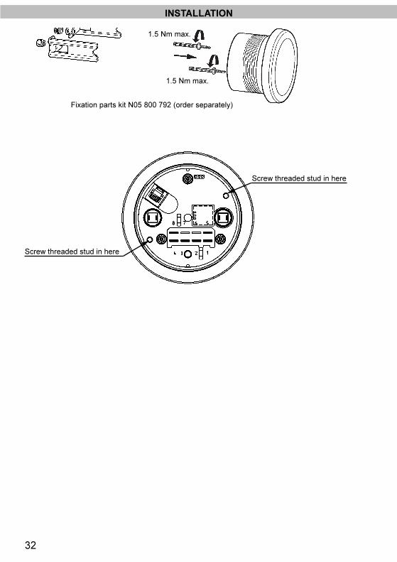
1.5 Nm max.
1.5 Nm max.
32
Screw threaded stud in here
Screw threaded stud in here
Fixation parts kit N05 800 792 (order separately)
INSTALLATION
olwind_e.qxd 21.06.99 13:35 Seite 32
33
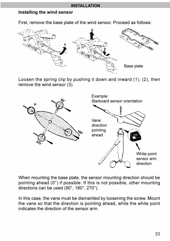
Installing the wind sensor
First, remove the base plate of the wind sensor. Proceed as follows:
Loosen the spring clip by pushing it down and inward (1), (2), thenremove the wind sensor (3).
When mounting the base plate, the sensor mounting direction should bepointing ahead (0°) if possible. If this is not possible, other mountingdirections can be used (90°, 180°, 270°).
In this case, the vane must be dismantled by loosening the screw. Mountthe vane so that the direction is pointing ahead, while the white pointindicates the direction of the sensor arm.
INSTALLATION
Base plate
Vanedirection pointingahead
White pointsensor armdirection
Example: Starboard sensor orientation
olwind_e.qxd 21.06.99 13:35 Seite 33

34
Depending on the structure of the mast, fix the base plate on the masttop, using suitable screws. Rotate the base plate over the oblong holesso that its central axis is parallel to the longitudinal ship axis, or to port orstarboard. Inclinations of the mast top can be compensated with thesensor footplate.Lateral mast mounting of the sensor is also possible.
Install the sensor on the base plate. Sensor inclinations can becompensated by changing pin and nut (A). In the case of lateral mastmounting loosen the nuts (A) and (B) and turn the sensor so that it isvertical to the midship axis.
INSTALLATION
olwind_e.qxd 21.06.99 13:35 Seite 34
35
INSTALLATION
Installing the mast cable
Do not sharply bend the mast cable. Avoid chafing.Shorten the mast cable to a length of the mast length plus 2 m. Place thestrain relief at the point where the cable enters the mast from the top.Use existing empty tubes to protect the mast cable (e.g. from chafing ofthe rakes), and install it with the mast down if possible.Install the other end of the mast cable from the indicating instrument tothe connecting socket at the foot of the mast.
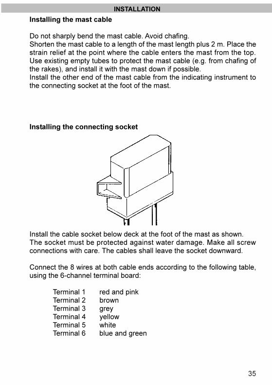
Installing the connecting socket
Install the cable socket below deck at the foot of the mast as shown.The socket must be protected against water damage. Make all screwconnections with care. The cables shall leave the socket downward.
Connect the 8 wires at both cable ends according to the following table,using the 6-channel terminal board:
Terminal 1 red and pinkTerminal 2 brownTerminal 3 greyTerminal 4 yellowTerminal 5 whiteTerminal 6 blue and green
olwind_e.qxd 21.06.99 13:35 Seite 35
36
INSTALLATION
Electrical installation
Setting the instrument for wind speed indication
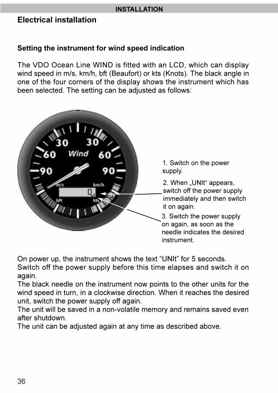
The VDO Ocean Line WIND is fitted with an LCD, which can displaywind speed in m/s, km/h, bft (Beaufort) or kts (Knots). The black angle inone of the four corners of the display shows the instrument which hasbeen selected. The setting can be adjusted as follows:
On power up, the instrument shows the text �UNIt� for 5 seconds. Switch off the power supply before this time elapses and switch it onagain. The black needle on the instrument now points to the other units for thewind speed in turn, in a clockwise direction. When it reaches the desiredunit, switch the power supply off again.The unit will be saved in a non-volatile memory and remains saved evenafter shutdown.The unit can be adjusted again at any time as described above.
2. When �UNIt� appears,switch off the power supplyimmediately and then switchit on again.
1. Switch on the power supply.
3. Switch the power supplyon again, as soon as theneedle indicates the desiredinstrument.
olwind_e.qxd 21.06.99 13:35 Seite 36
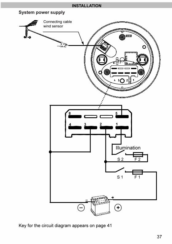
System power supply
37
INSTALLATION
� +
F 1
F 2
S 1
S 2
123
58
Illumination
4
Key for the circuit diagram appears on page 41
Connecting cablewind sensor
olwind_e.qxd 21.06.99 13:35 Seite 37

Connecting an analog wind speed indicating instrument
An analog wind velocity indicating instrument can be connected to theOcean Line Wind installation as an accessory. It shows the apparentwind speed.
Mount the wind speed indicating instrument as the main indicatinginstrument (see page 11). The maximum length of the cable between themain indicating instrument and the wind speed indicating instrument is10 m.
The power for the wind speed indicating instrument is to be supplied inthe same way as for the main indicating instrument (see page 17). Theindicating instrument power supply must be switched on at the sametime.
38
INSTALLATION
olwind_e.qxd 21.06.99 13:35 Seite 38
39
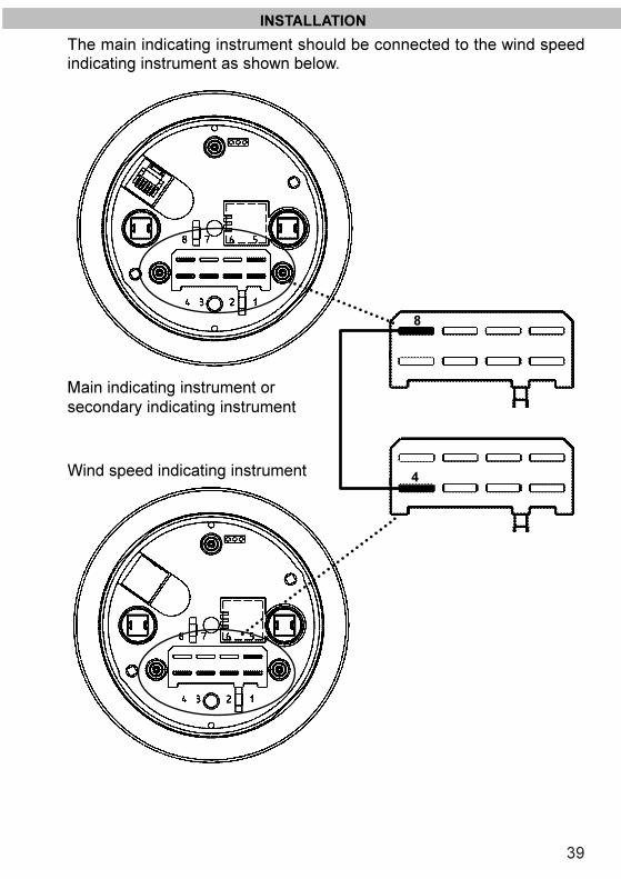
INSTALLATION
The main indicating instrument should be connected to the wind speedindicating instrument as shown below.
Main indicating instrument orsecondary indicating instrument
Wind speed indicating instrument 4
8
olwind_e.qxd 21.06.99 13:35 Seite 39
40
INSTALLATION
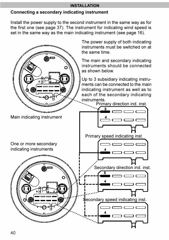
Connecting a secondary indicating instrument
Install the power supply to the second instrument in the same way as forthe first one (see page 37). The instrument for indicating wind speed isset in the same way as the main indicating instrument (see page 16).
The power supply of both indicatinginstruments must be switched on atthe same time.
The main and secondary indicatinginstruments should be connectedas shown below.
Up to 3 subsidiary indicating instru-ments can be connected to the mainindicating instrument as well as toeach of the secondary indicatinginstruments.
Main indicating instrument
One or more secondaryindicating instruments 4
4
8
4
8
4
Primary speed indicating inst.
Secondary speed indicating inst.
Primary direction ind. inst.
Secondary direction ind. inst.
olwind_e.qxd 21.06.99 13:35 Seite 40

41
Key for circuit diagram
S1 On/Off switch for navigation instrumentsS2 On/Off switch for instrument lightingF1 Fuse for navigation instruments (5 A)F2 Fuse for instrument lighting (5 A)
Recommended cable section: 1.5 mm2
Cable lengths
Wind sensor - indicating instrument 20 m max.Indicating instrument - second instrument 10 m max.Second instrument - third instrument 10 m max.
Technical data
Measuring principle: Vane with inductive transmission, Cup anemo-meter with Hall chip
Accuracy direction ± 3°speed ± 2 km/h (0�60 km/h)
Resolution: Direction 1°, Speed 1 km/hSupply voltage 10.8 to 30 V DCCurrent consumption: about 140 mA at 12 V DC without lighting
about 300 mA with lightingOperating temperature �10 to +60°CType of protection IP 65 at front per IEC 529EMC protection CE: EN 50081-1, EN 50082-1Dimensions: Indicating instrument:
Front ring diam..: 105 mmInstallation diam..: 86 mmInstallation depth (with union nut): 56 mmInstallation depth (with bracket): 90 mmCompass sensor: See figure page 37
Technical modifications reserved.
INSTALLATION / DATA
olwind_e.qxd 21.06.99 13:35 Seite 41
08 6
01 2
0906
/99
-
Wind
VDO Kienzle Vertrieb und Service GmbHKruppstrasse 105D-60388 Frankfurt am MainTel.: +49 (0)69 40805-0Fax: +49 (0)69 40805-177e-mail: [email protected]: www.vdokienzle.com/marine
olwind~1.qxd 09.11.99 08:34 Seite 2