Monochrome Line Scan Camera SK5150VJR-L - … · syntax defined by the GenApi module of the...
20
Kieler Str. 212, 22525 Hamburg, Germany • Tel: +49 40 85 39 97-0 • Fax: +49 40 85 39 97-79 • [email protected] • www.SuKHamburg.de SK5150VJR-L Line Scan Camera SK5150VJR-L Manual (v. 3.2012) Monochrome Line Scan Camera SK5150VJR-L 5152 pixels, 7 µm x 7 µm, 40 / 20 MHz pixel frequency 1) Longer exposure times are possible in trigger mode "exposure active". Contents Line scan cameras from Schäfter+Kirchhoff are supplied factory-preset for the particular application. If you are not familiar with line scan cameras, or their operation using the supplied software, then consult the glossary in Section 12. Line Scan Camera Fundamentals, p 18. 1. Gigabit Ethernet Interface 2 2. Connections and I/O Signals 3 3. Hardware and Software Requirements 4 4. Hardware and Software Installation: GigE Setup 5 5. Scanning with SkGEVTool and GEV Device Control 6 5.1 Camera Control 7 5.2 Gain and Offset Controls 7 5.3 Shading Correction 8 5.4 Generating an Image – Scanning a Surface 8 6. Serial Commands 9 7. GEV Device Feature List 10 8. Settings of Control Register 12 9. Advanced Synchronization Control 13 10. Sensor Performance Specifications 14 11. Dimensions 17 12. Line Scan Camera Fundamentals 18 12.1 Features and Characteristics 18 12.2 Alignments and Adjustments 19 13. Warranty 20 14. Accessories 20 Section Page Section Page CCD line scan camera SK5150VJR-L with Clamp set SK5101 Mounting bracket SK5105-L Focus adapter FA22R-45 Enlarging lens APO-Rodagon N 4.0/80 1 2 3 4 5 3 2 4 1 5 Camera SK5150VJR-L Sensor Single Line Sensor Type ILX 531A Pixel number 5152 Pixel size 7 µm x 7 µm Pixel spacing 7 µm Sensor width 7 µm Active length 36.0 mm Anti-Blooming no Integration Control no Shading Correction yes Window Function (ROI) yes Pixel frequency 40 MHz Line frequency max 7.52 kHz Line frequency min 0.05 kHz Integration time max 15.3 ms 1) Integration time min 0.133 ms Dynamic range 1:500 (rms) Spectral range 400 – 900 nm Video signal monochrome 8/10/12-bit digital Interface GigE Vision TM Voltage +5 V, +15 V Power consumption 3.5 W Casing (W x H x D) 65 mm x 65 mm x 73 mm Objective mount M45 x 0.75 Weight 0.2 kg Working temperature +5°C to +45°C
Transcript of Monochrome Line Scan Camera SK5150VJR-L - … · syntax defined by the GenApi module of the...
Kieler Str. 212, 22525 Hamburg, Germany • Tel: +49 40 85 39 97-0 • Fax: +49 40 85 39 97-79 • [email protected] • www.SuKHamburg.de
SK
5150
VJR
-LLine Scan Camera SK5150VJR-L Manual (v. 3.2012)
Monochrome Line Scan CameraSK5150VJR-L 5152 pixels, 7 µm x 7 µm, 40 / 20 MHz pixel frequency
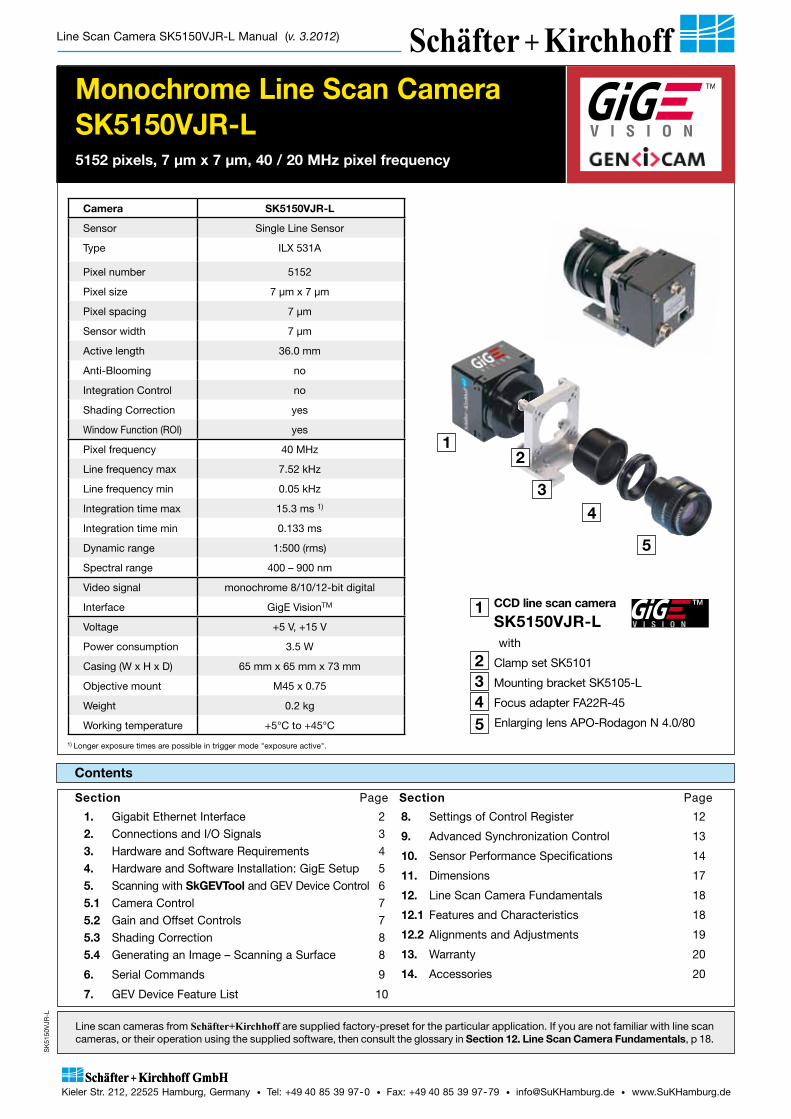
1) Longer exposure times are possible in trigger mode "exposure active".
Contents
Line scan cameras from Schäfter+Kirchhoff are supplied factory-preset for the particular application. If you are not familiar with line scan cameras, or their operation using the supplied software, then consult the glossary in Section 12. Line Scan Camera Fundamentals, p 18.
1. Gigabit Ethernet Interface 22. Connections and I/O Signals 33. Hardware and Software Requirements 44. Hardware and Software Installation: GigE Setup 55. Scanning with SkGEVTool and GEV Device Control 65.1 Camera Control 75.2 Gain and Offset Controls 75.3 Shading Correction 85.4 Generating an Image – Scanning a Surface 8
6. Serial Commands 9
7. GEV Device Feature List 10
8. Settings of Control Register 12
9. Advanced Synchronization Control 13
10. Sensor Performance Specifications 14
11. Dimensions 17
12. Line Scan Camera Fundamentals 18
12.1 Features and Characteristics 18
12.2 Alignments and Adjustments 19
13. Warranty 20
14. Accessories 20
Section Page Section Page
CCD line scan camera
SK5150VJR-L
with
Clamp set SK5101
Mounting bracket SK5105-L
Focus adapter FA22R-45
Enlarging lens APO-Rodagon N 4.0/80
1
2345
3
2
4
1
5
Camera SK5150VJR-L
Sensor Single Line Sensor
Type ILX 531A
Pixel number 5152
Pixel size 7 µm x 7 µm
Pixel spacing 7 µm
Sensor width 7 µm
Active length 36.0 mm
Anti-Blooming no
Integration Control no
Shading Correction yes
Window Function (ROI) yes
Pixel frequency 40 MHz
Line frequency max 7.52 kHz
Line frequency min 0.05 kHz
Integration time max 15.3 ms 1)
Integration time min 0.133 ms
Dynamic range 1:500 (rms)
Spectral range 400 – 900 nm
Video signal monochrome 8/10/12-bit digital
Interface GigE VisionTM
Voltage +5 V, +15 V
Power consumption 3.5 W
Casing (W x H x D) 65 mm x 65 mm x 73 mm
Objective mount M45 x 0.75
Weight 0.2 kg
Working temperature +5°C to +45°C
Page 2
Line Scan Camera SK5150VJR-L Manual (v. 3.2012)
1. Gigabit Ethernet Interface
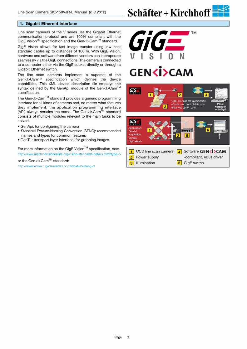
Line scan cameras of the V series use the Gigabit Ethernet communication protocol and are 100% compliant with the GigE VisionTM specification and the Gen<I>CamTM standard.
GigE Vision allows for fast image transfer using low cost standard cables up to distances of 100 m. With GigE Vision, hardware and software from different vendors can interoperate seamlessly via the GigE connections. The camera is connected to a computer either via the GigE socket directly or through a Gigabit Ethernet switch.
The line scan cameras implement a superset of the Gen<I>Cam™ specification which defines the device capabilities. This XML device description file employs the syntax defined by the GenApi module of the Gen<I>CamTM specification.
The Gen<I>CamTM standard provides a generic programming interface for all kinds of cameras and, no matter what features they implement, the application programming interface (API) always remains the same. The Gen<I>CamTM standard consists of multiple modules relevant to the main tasks to be solved:
• GenApi: for configuring the camera• Standard Feature Naming Convention (SFNC): recommended
names and types for common features• GenTL: transport layer interface, for grabbing images
For more information on the GigE VisionTM specification, see: http://www.machinevisiononline.org/vision-standards-details.cfm?type=5
or the Gen<I>CamTM standard:http://www.emva.org/cms/index.php?idcat=27&lang=1
Application:Parallel acquisition using a GigE switch
PCorNotebookwith GigE
GigE inter face for transmission of video and control data over distances up to 100 m
4
4
2
21
1
3
5
CCD line scan camera
2 Power supply
3 Illumination
Software Gen<i>Cam
-compliant, eBus driver
GigE switch
1 4
5
Page 3
Line Scan Camera SK5150VJR-L Manual (v. 3.2012)
2. Connections and I/O Signals
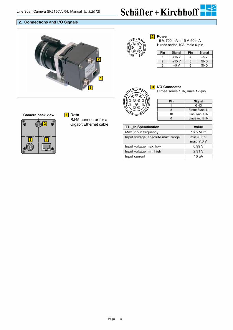
Camera back view Data RJ45 con nector for a Gigabit Ethernet cable
21
3
45
6
7
89
10
11122
1
34
5
6
Power+5 V, 700 mA +15 V, 50 mAHirose series 10A, male 6-pin
21
3
45
6
7
89
10
11122
1
34
5
6
1
2
3
1
1
2
3 I/O ConnectorHirose series 10A, male 12-pin
3
2
Pin Signal1 GND8 FrameSync IN10 LineSync A IN6 LineSync B IN
Pin Signal Pin Signal1 +15 V 4 +5 V2 +15 V 5 GND3 +5 V 6 GND
TTL_In Specification ValueMax. input frequency 16.5 MHzInput voltage, absolute max. range min -0.5 V
max 7.0 VInput voltage max. low 0.99 VInput voltage min. high 2.31 VInput current 10 µA
Page 4
Line Scan Camera SK5150VJR-L Manual (v. 3.2012)
3. Hardware and Software Requirements
Hardware
To optimize the Network Adapter, open the Device Manager and go to Advanced Properties of the Adapter
Recommended optimization values:• Receive Descriptors/Empfangsdescriptors = 2048• Interrupt Moderation Rate/Interrupt-Drosselungsrate=extreme• Jumbo Frames = 9014 Byte
eBUS Driver Installation Tool – allows choice of the best driver according to needs.
With the installed eBus driver, the additional optimization of the network adapter is not necessary
Trouble-shooting:If the camera cannot connect properly with the NIC or has acquisition timeout errors, there may be a conflict between the eBus Optimal driver and a third party filter driver. In this case, install the eBus Universal Driver or install the driver supplied by the manufacturer and use the filter driver of the third party software.
PC:• Intel Pentium 4 or AMD equivalent• RAM min. 1 GB, depending on size of acquired images• High-performance video card using either an AGP bus or
PCIe bus• Operating System: Windows XP, Windows Vista, Windows 7
(32-bit and 64-bit) are supported
Network Adapters:• Any Gigabit Ethernet network adapter as a card or on the
motherboard is suitable. For the best performance, a NIC with Intel PRO/1000 chip is recommended.
• PCIe adapters outperform PCI adapters.• Network adapters that support Jumbo Frames outperform
adapters with fixed packet-size frames.
Optimizing the Network Adapter (not eBus Optimal driver)Most Gigabit network interface controllers allow the user to modify their parameters, such as Adapter Buffers and Jumbo Frames. These should be optimized during installation in the Advanced Properties of the Network Adapter.
The line scan cameras of the V series work with any software that is Gen<I>CamTM compliant and that supports GigE Vision cameras. Most software products provide their own network filter driver for a better performance and, where available, this filter driver should be installed.
If no special software is available then the recommended software is the eBUS PureGEV Package from Pleora: http://www.pleora.com
The software package contains a SDK and two kinds of eBus drivers (instead of a filter driver).
1. The eBUS Universal Driver – ideal for most real-time vision applications. It runs on almost any vendor NIC, handles all IP transport protocols – including ordinary network traffic and GigE Vision transport protocols – and has less CPU usage than a filter driver.
2. The eBUS Optimal Driver – ideal for applications with a very heavy processing overhead. It runs on the Intel PRO/1000 family of NICs, handles all IP transport protocols – including ordinary network traffic and GigE Vision transport protocols – and exhibits the lowest CPU load in the industry.
Software
Page 5
Line Scan Camera SK5150VJR-L Manual (v. 3.2012)
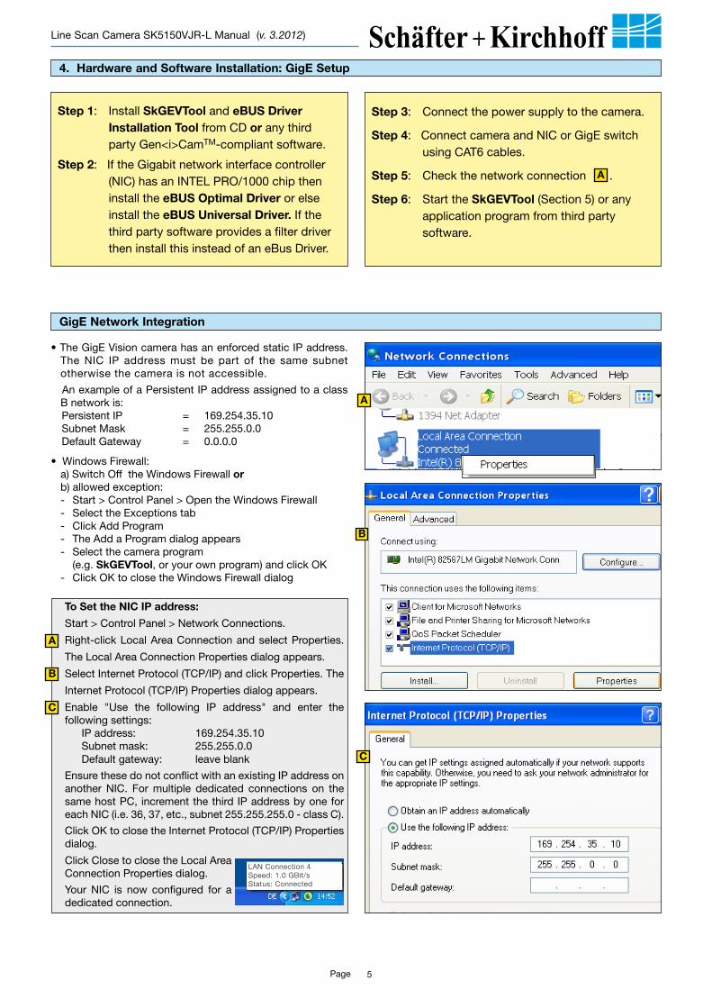
To Set the NIC IP address:
Start > Control Panel > Network Connections.
Right-click Local Area Connection and select Properties.
The Local Area Connection Properties dialog appears.
Select Internet Protocol (TCP/IP) and click Properties. The
Internet Protocol (TCP/IP) Properties dialog appears.
Enable "Use the following IP address" and enter the following settings: IP address: 169.254.35.10 Subnet mask: 255.255.0.0 Default gateway: leave blank
Ensure these do not conflict with an existing IP address on another NIC. For multiple dedicated connections on the same host PC, increment the third IP address by one for each NIC (i.e. 36, 37, etc., subnet 255.255.255.0 - class C).
Click OK to close the Internet Protocol (TCP/IP) Properties dialog.
Click Close to close the Local Area Connection Properties dialog.
Your NIC is now configured for a dedicated connection.
• The GigE Vision camera has an enforced static IP address. The NIC IP address must be part of the same subnet otherwise the camera is not accessible.
An example of a Persistent IP address assigned to a class B network is:
Persistent IP = 169.254.35.10 Subnet Mask = 255.255.0.0 Default Gateway = 0.0.0.0
• Windows Firewall:a) Switch Off the Windows Firewall orb) allowed exception:- Start > Control Panel > Open the Windows Firewall- Select the Exceptions tab- Click Add Program- The Add a Program dialog appears- Select the camera program (e.g. SkGEVTool, or your own program) and click OK- Click OK to close the Windows Firewall dialog
A
B
C
Step 3: Connect the power supply to the camera.
Step 4: Connect camera and NIC or GigE switch using CAT6 cables.
Step 5: Check the network connection .
Step 6: Start the SkGEVTool (Section 5) or any application program from third party software.
4. Hardware and Software Installation: GigE Setup
GigE Network Integration
Step 1: Install SkGEVTool and eBUS Driver Installation Tool from CD or any third party Gen<i>CamTM-compliant software.
Step 2: If the Gigabit network interface controller (NIC) has an INTEL PRO/1000 chip then install the eBUS Optimal Driver or else install the eBUS Universal Driver. If the third party software provides a filter driver then install this instead of an eBus Driver.
A
A
B
C
LAN Connection 4Speed: 1.0 GBit/sStatus: Connected
Page 6
Line Scan Camera SK5150VJR-L Manual (v. 3.2012)
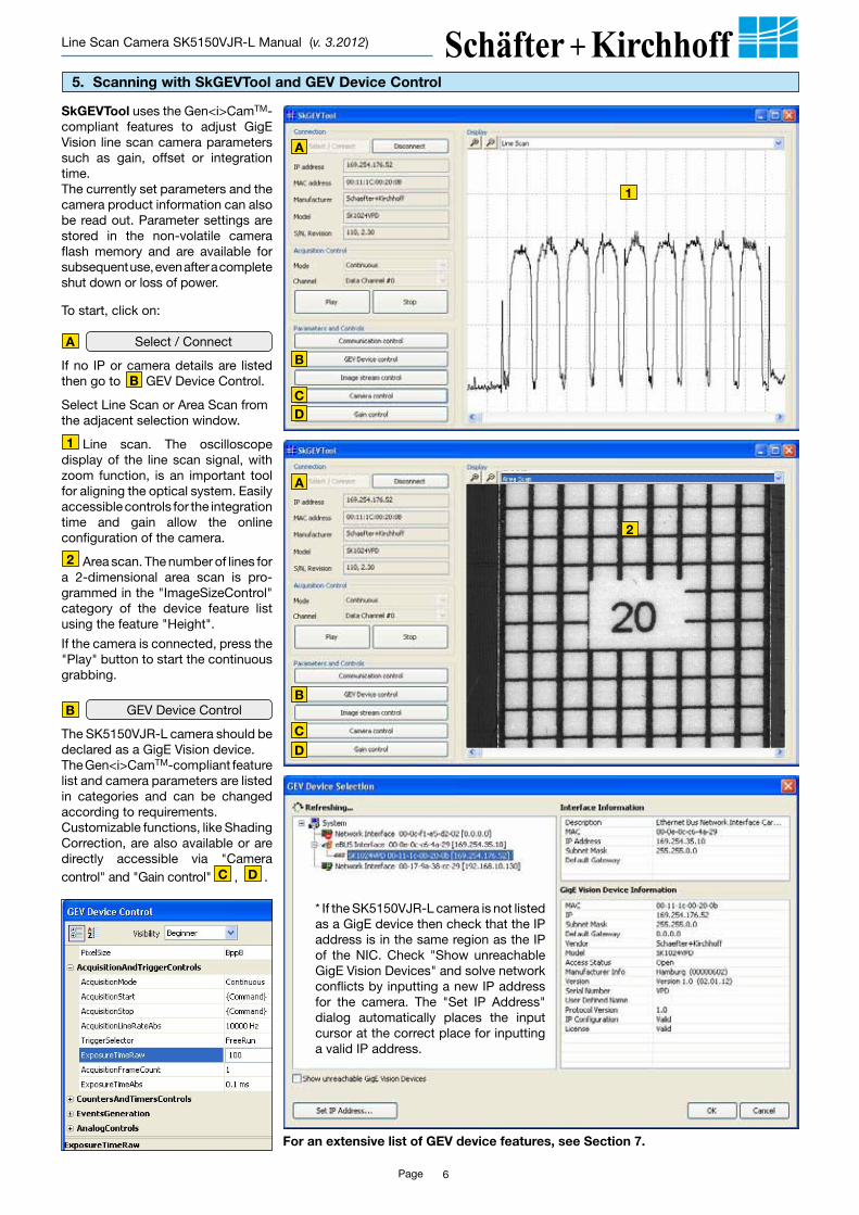
SkGEVTool uses the Gen<i>CamTM-compliant features to adjust GigE Vision line scan camera parameters such as gain, offset or integration time. The currently set parameters and the camera product information can also be read out. Parameter settings are stored in the non-volatile camera flash memory and are available for subsequent use, even after a complete shut down or loss of power.
To start, click on:
Select / Connect
If no IP or camera details are listed then go to GEV Device Control.
Select Line Scan or Area Scan from the adjacent selection window.
Line scan. The oscillos cope display of the line scan signal, with zoom function, is an important tool for aligning the optical system. Easily accessible controls for the integration time and gain allow the online configuration of the camera.
Area scan. The number of lines for a 2-dimensional area scan is pro-grammed in the "ImageSizeControl" category of the device feature list using the feature "Height".
If the camera is connected, press the "Play" button to start the continuous grabbing.
GEV Device Control
The SK5150VJR-L camera should be declared as a GigE Vision device. The Gen<i>CamTM-compliant feature list and camera parameters are listed in categories and can be changed according to requirements. Customizable functions, like Shading Correction, are also available or are directly accessible via "Camera control" and "Gain control" C , D .
5. Scanning with SkGEVTool and GEV Device Control
1
1
A
B
BCD
A
* If the SK5150VJR-L camera is not listed as a GigE device then check that the IP address is in the same region as the IP of the NIC. Check "Show unreachable GigE Vision Devices" and solve network conflicts by inputting a new IP address for the camera. The "Set IP Address" dialog automatically places the input cursor at the correct place for inputting a valid IP address.
B
2
2
B
C
D
A
For an extensive list of GEV device features, see Section 7.
Page 7
Line Scan Camera SK5150VJR-L Manual (v. 3.2012)
FrameStart
ExtSync
Video
VideoValid
Datatransmission
Timing: Frame Sync + trigger mode "LineStart"
Line Trigger Modes
Free Run: Each line is acquired and the next scan is started automatically on completion of the previous line scan.Line Start: The triggered line is read out at the next line clock. The start and time of exposure are controlled internally by the camera and are not affected by the trigger. The exposure time is programmable and the trigger clock does not affect the exposure time.
Exposure Start: A new exposure is started exactly at the time of triggering. The programmed exposure time is unaffected by the trigger clock.Exposure Active: The exposure time is controlled by the external trigger signal.Sync divider: Divides the external trigger frequency by a programmed integer. Only every n-th line is recorded.
Frame Trigger Mode The Frame Trigger synchronizes the acquisition of 2D area scans. The individual line scans in this area scan can be synchronized either in free run mode or triggered externally.The camera suppresses the data transfer until a falling edge of a TTL signal occurs at ’FrameStart’ input (useful for control by the breaching of a light barrier, for example).
Synchronization
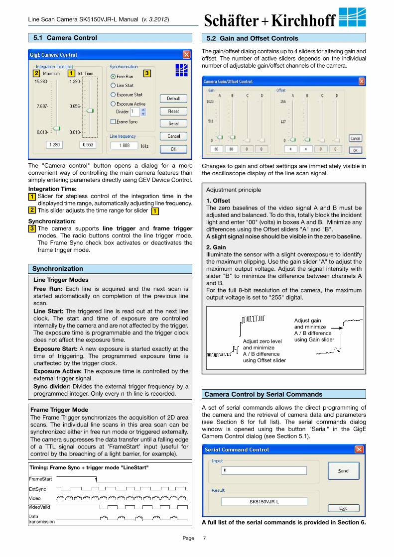
5.1 Camera Control
The "Camera control" button opens a dialog for a more convenient way of controlling the main camera features than simply entering parameters directly using GEV Device Control.
Integration Time: Slider for stepless control of the integration time in the displayed time range, automatically adjusting line frequency. This slider adjusts the time range for slider
Synchronization: The camera supports line trigger and frame trigger modes. The radio buttons control the line trigger mode. The Frame Sync check box activates or deactivates the frame trigger mode.
12
1
2 1
3
3
5.2 Gain and Offset Controls
The gain/offset dialog contains up to 4 sliders for altering gain and offset. The number of active sliders depends on the individual number of adjustable gain/offset channels of the camera.
Changes to gain and offset settings are immediately visible in the oscilloscope display of the line scan signal.
Adjustment principle
1. OffsetThe zero baselines of the video signal A and B must be adjusted and balanced. To do this, totally block the incident light and enter "00" (volts) in boxes A and B. Minimize any differences using the Offset sliders "A" and "B". Aslightsignalnoiseshouldbevisibleinthezerobaseline.
2. GainIlluminate the sensor with a slight overexposure to identify the maximum clipping. Use the gain slider "A" to adjust the maximum output voltage. Adjust the signal intensity with slider "B" to minimize the difference between channels A and B.For the full 8-bit resolution of the camera, the maximum output voltage is set to "255" digital.
Adjust gainand minimizeA / B difference using Gain sliderAdjust zero level
and minimizeA / B differenceusing Offset slider
Camera Control by Serial Commands
A set of serial commands allows the direct programming of the camera and the retrieval of camera data and parameters (see Section 6 for full list). The serial commands dialog window is opened using the button "Serial" in the GigE Camera Control dialog (see Section 5.1).
A full list of the serial commands is provided in Section 6.
SK5150VJR-L
Page 8
Line Scan Camera SK5150VJR-L Manual (v. 3.2012)
5.4 Generating an Image – Scanning a Surface
A two-dimensional image is generated by moving the object or the camera. The direction of the translation movement must be orthogonal to the sensor axis of the CCD line scan camera. To obtain a proportional image with the correct aspect ratio, a line synchronous transport with the laterally correct pixel assignment is required.
The optimal object scan rate is calculated from:
WP • fLVO = ß
where VO = object scan velocityWP = pixel widthfL = line frequencyß = magnificationS = sensor lengthFOV = Field Of View
magnification = sensor length / Field Of View.
Pixel 1CCD Sensor
Objectstructure
VO
FOV
vS
WP
Example:
Object scan velocity for a given FOV and line frequency:
Camera: SK5150VJR-L
Pixelsize =7µmLinefrequency =7kHzS =36.0mmFOV =290mm
VO =0.007mm*7000/(36.0/290)s
VO =394.7mm/s
If the velocity of the object carrier is not adjustable then the line frequency of the camera must be adjusted to provide an image with the correct aspect ratio, where:
VO • ßfL = WP
5.3 Shading Correction
Shading Correction (or flat-field compensation) is used to compensate for non-uniform illumination of the line sensor as well as for lens vignetting.Before Shading Correction can be used, a reference signal from a homogeneous white calibration target is acquired. This reference signal is used by the Shading Correction algorithm to calculate an individual amplification factor for each pixel, scaling each value to the signal maximum (e.g. 4095 for a bit depth of 12) and producing a corrected flat maximum signal.This acquired Shading Correction reference signal is stored in the Shading Correction Memory (SCM) within the camera. Whenever Shading Correction is active then each acquired line scan will be corrected by the SCM contents. The SCM can be stored permanently within the camera by writing it into the non-volatile flash memory before powering the camera off.
Shading correction with SkGEVTool
The signal from a monochrome CCD line scan camera using a homogeneous white calibration target with signal reduction caused by either lens vignetting or inhomogeneous object illumination.
CCD line scan camera signal after shading correction.
In GEV Device Control, the following custom features can be used for Shading Correction: SkShadCorrReference: for acquisition of reference signalSkSaveScmToFlash: for writing the SCM values into flashSkSetShadingCorrection:ON = Shading Correction is active OFF= deactivated
A
B
A
B
On startup, the camera resorts to the shading correction status last used. If previously activated then shading correction will be used for adjusting the signal. If previously deactivated then a raw line signal is produced without any shading correction.
v
V
V
V
V
v
v
Page 9
Line Scan Camera SK5150VJR-L Manual (v. 3.2012)
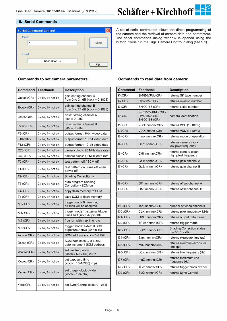
6. Serial Commands
Command Feedback Description
K<CR> SK5150VJR-L<CR> returns SK type number
R<CR> Rev2.35<CR> returns revision number
S<CR> SNr00163<CR> returns serial number
I<CR>SK5150VJR-L<CR>Rev2.35<CR>SNr00163<CR>
camera identification
I1<CR> VCC: nnnnn<CR> returns VCC (1=10mV)
I2<CR> VDD: nnnnn<CR> returns VDD (1=10mV)
I3<CR> moo: nnnnn<CR> returns mode of operation
I4<CR> CLo: nnnnn<CR>returns camera clock:low pixel frequency
I5<CR> CHi: nnnnn<CR>returns camera clock: high pixel frequency
I6<CR> Ga1: nnnnn<CR> returns gain channel A
I7<CR> Ga2: nnnnn<CR> returns gain channel B
I8<CR> Of1: nnnnn <CR> returns offset channel A
I9<CR> Of2: nnnnn <CR> returns offset channel B
I19<CR> Tab: nnnnn<CR> number of video channels
I20<CR> CLK: nnnnn<CR> returns pixel frequency (MHz)
I21<CR> ODF: nnnnn<CR> returns output data format
I22<CR> TRM: nnnnn<CR> returns trigger mode
I23<CR> SCO: nnnnn<CR>Shading Correction status0 = off, 1 = on
I24<CR> Exp: nnnnn<CR> returns exposure time (µs)
I25<CR> miX: nnnnn<CR>returns minimum exposure time (µs)
I26<CR> LCK: nnnnn<CR> returns line frequency (Hz)
I27<CR> maZ: nnnnn<CR>returns maximum line frequency (Hz)
I28<CR> TSc: nnnnn<CR> returns trigger clock divider
I29<CR> SyC: nnnnn<CR> returns Sync Control
Commands to read data from camera: Commands to set camera parameters:
Command Feedback Description
Gxxxx<CR> 0= ok, 1= not ok gain setting channel A from 0 to 24 dB (xxxx = 0-1023)
Bxxxx<CR> 0= ok, 1= not okgain setting channel B from 0 to 24 dB (xxxx = 0-1023)
Oxxx<CR> 0= ok, 1= not okoffset setting channel A (xxx = 0-255)
Pxxx<CR> 0= ok, 1= not okoffset setting channel B (xxx = 0-255)
F8<CR> 0= ok, 1= not ok output format: 8-bit video data
F10<CR> 0= ok, 1= not ok output format: 10-bit video data
F12<CR> 0= ok, 1= not ok output format: 12-bit video data
C20<CR> 0= ok, 1= not ok camera clock: 20 MHz data rate
C40<CR> 0= ok, 1= not ok camera clock: 40 MHz data rate
T0<CR> 0= ok, 1= not ok test pattern off / SCM off
T1<CR> 0= ok, 1= not oktest pattern on (turns off when power off)
T2<CR> 0= ok, 1= not ok Shading Correction on
T3<CR> 0= ok, 1= not okauto program Shading Correction / SCM on
T4<CR> 0= ok, 1= not ok copy flash memory to SCM
T5<CR> 0= ok, 1= not ok save SCM to flash memory
M0<CR> 0= ok, 1= not oktrigger mode 0: free run,all lines will be acquired
M1<CR> 0= ok, 1= not oktrigger mode 1: external trigger Line Start (input J2 pin 10)
M2<CR> 0= ok, 1= not ok free run with max line rate
M5<CR> 0= ok, 1= not oktrigger mode: external SOSExposure Active (J2 pin 10)
Axxxx<CR> 0= ok, 1= not ok SCM address (xxxx = 0-8159)
Dxxxx<CR> 0= ok, 1= not okSCM data (xxxx = 0-4095), auto increment SCM address
Wxxxxx<CR> 0= ok, 1= not okset line frequency(xxxxx= 50-7142) in Hz
Xxxxxx<CR> 0= ok, 1= not okset exposure time(xxxxx= 10-16383) in µs
Vxxxxx<CR> 0= ok, 1= not okset trigger clock divider(xxxxx= 1-32767)
Yxxx<CR> 0= ok, 1= not ok set Sync Control (xxx= 0 - 255)
A set of serial commands allows the direct programming of the camera and the retrieval of camera data and parameters. The serial commands dialog window is opened using the button "Serial" in the GigE Camera Control dialog (see 5.1).
SK5150VJR-L
Page 10
Line Scan Camera SK5150VJR-L Manual (v. 3.2012)
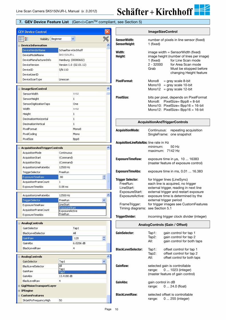
7. GEV Device Feature List (Gen<i>CamTM compliant, see Section 5)
ImageSizeControl
SensorWidth: number of pixels in line sensor (fixed)SensorHeight: 1 (fixed)
Width: image width = SensorWidth (fixed)Height: image height (number of lines per image) 1 (fixed) for Line Scan mode 2 - 32000 for Area Scan mode Grab Must be stopped before
changing Height feature
PixelFormat: Mono8 = gray scale 8-bit Mono10 = gray scale 10-bit Mono12 = gray scale 12-bit
PixelSize: bits per pixel, depends on PixelFormat Mono8: PixelSize= Bpp8 = 8-bit Mono10: PixelSize= Bpp16 = 16-bit Mono12: PixelSize= Bpp16 = 16-bit
AcquisitionAndTriggerControls
AcquisitionMode: Continuous: repeating acquisition SingleFrame: one snapshot
AcquisitionLineRateAbs: line rate in Hz minimum: 50 Hz maximum: 7142 Hz
ExposureTimeRaw: exposure time in µs, 10 ... 16383 (master feature of exposure control)
ExposureTimeAbs: exposure time in ms, 0.01 ... 16.383
TriggerSelector: for trigger lines (LineSync) FreeRun: each line is acquired, no trigger LineStart: external trigger, reading in next line ExposureStart: external trigger and restart exposure ExposureActive: exposure time is determined by the
external trigger period FrameTrigger: for trigger images see CustomFeatures Timing diagrams: see Section 5.1
TriggerDivider: incoming trigger clock divider (integer)
AnalogControls (Gain / Offset)
GainSelector: Tap1: gain control for tap 1 Tap2: gain control for tap 2 All: gain control for both taps
BlackLevelSelector: Tap1: offset control for tap 1 Tap2: offset control for tap 2 All: offset control for both taps
GainRaw: selected gain is controllable range: 0 ... 1023 (integer) (master feature of gain control)
GainAbs: gain control in dB range: 0 ... 24.0 (float)
BlackLevelRaw: selected offset is controllable range: 0 ... 255 (integer)
SK5150VJR-L
5152
5152
Page 11
Line Scan Camera SK5150VJR-L Manual (v. 3.2012)
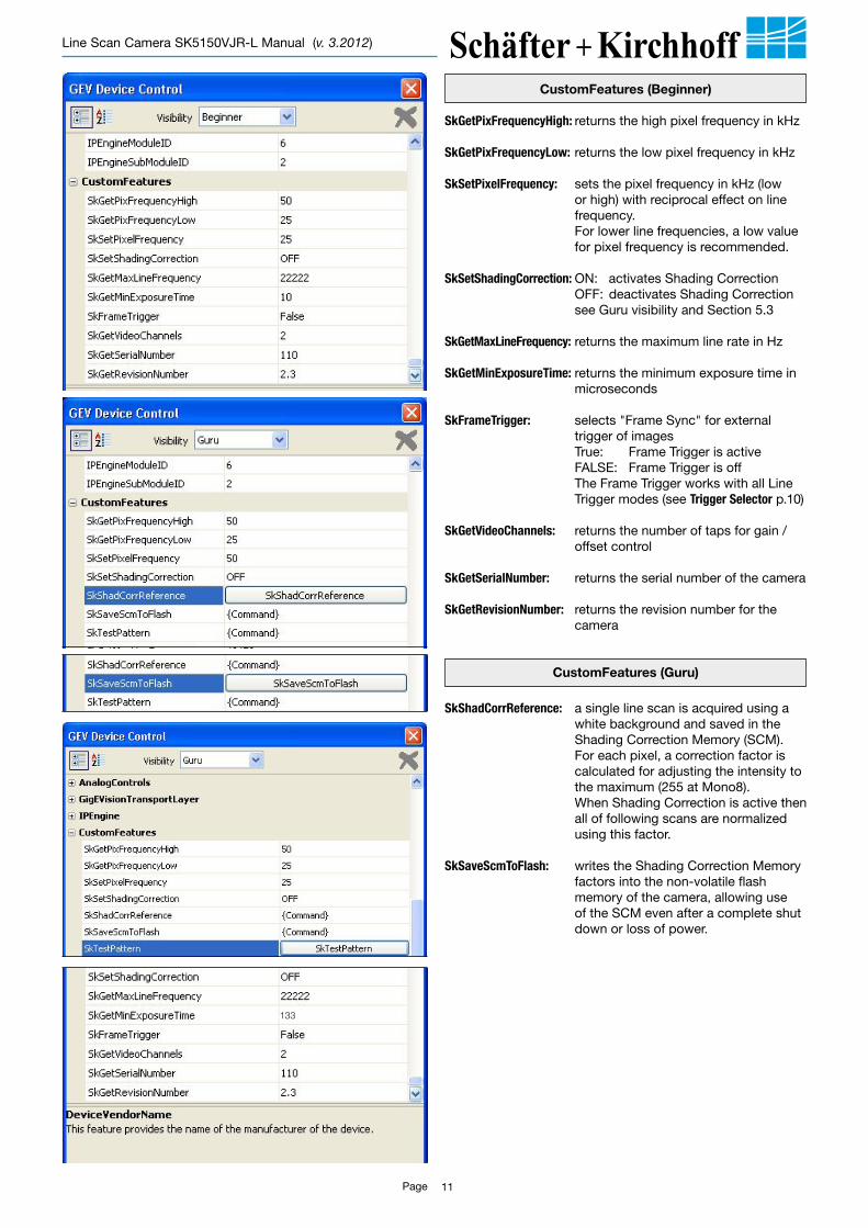
CustomFeatures (Beginner)
SkGetPixFrequencyHigh:returns the high pixel frequency in kHz
SkGetPixFrequencyLow:returns the low pixel frequency in kHz
SkSetPixelFrequency: sets the pixel frequency in kHz (low or high) with reciprocal effect on line frequency.
For lower line frequencies, a low value for pixel frequency is recommended.
SkSetShadingCorrection: ON: activates Shading Correction OFF: deactivates Shading Correction see Guru visibility and Section 5.3
SkGetMaxLineFrequency:returns the maximum line rate in Hz
SkGetMinExposureTime:returns the minimum exposure time in microseconds
SkFrameTrigger: selects "Frame Sync" for external trigger of images
True: Frame Trigger is active FALSE: Frame Trigger is off The Frame Trigger works with all Line
Trigger modes (see TriggerSelector p.10)
SkGetVideoChannels: returns the number of taps for gain /offset control
SkGetSerialNumber: returns the serial number of the camera
SkGetRevisionNumber: returns the revision number for the camera
CustomFeatures (Guru)
SkShadCorrReference: a single line scan is acquired using a white background and saved in the Shading Correction Memory (SCM).
For each pixel, a correction factor is calculated for adjusting the intensity to the maximum (255 at Mono8). When Shading Correction is active then all of following scans are normalized using this factor.
SkSaveScmToFlash: writes the Shading Correction Memory factors into the non-volatile flash memory of the camera, allowing use of the SCM even after a complete shut down or loss of power.
133
Page 12
Line Scan Camera SK5150VJR-L Manual (v. 3.2012)
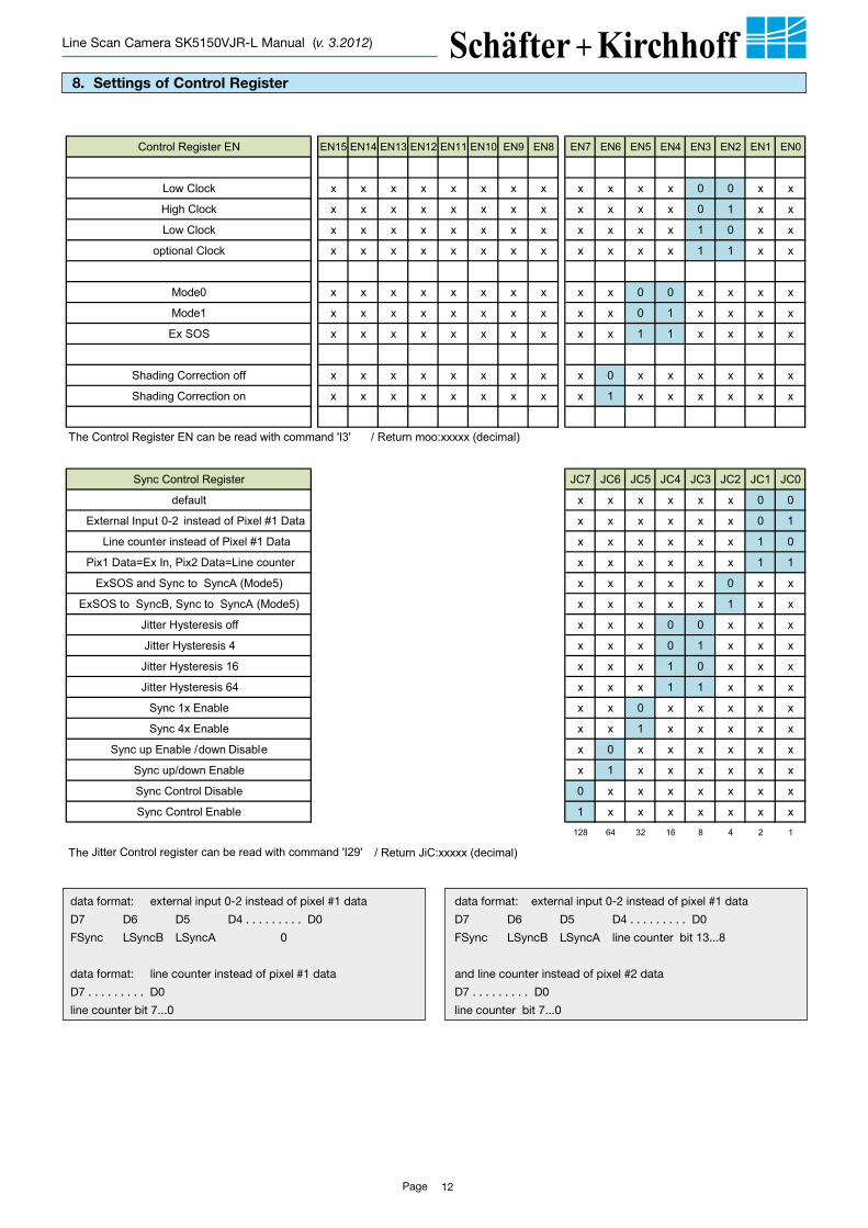
8. Settings of Control Register
data format: external input 0-2 instead of pixel #1 data
D7 D6 D5 D4 . . . . . . . . . D0
FSync LSyncB LSyncA 0
data format: line counter instead of pixel #1 data
D7 . . . . . . . . . D0
line counter bit 7...0
Control Register EN EN15 EN14 EN13 EN12 EN11 EN10 EN9 EN8 EN7 EN6 EN5 EN4 EN3 EN2 EN1 EN0
Low Clock x x x x x x x x x x x x 0 0 x x
High Clock x x x x x x x x x x x x 0 1 x x
Low Clock x x x x x x x x x x x x 1 0 x x
optional Clock x x x x x x x x x x x x 1 1 x x
Mode0 x x x x x x x x x x 0 0 x x x x
Mode1 x x x x x x x x x x 0 1 x x x x
Ex SOS x x x x x x x x x x 1 1 x x x x
Shading Correction off x x x x x x x x x 0 x x x x x x
Shading Correction on x x x x x x x x x 1 x x x x x x
Sync Control Register JC7 JC6 JC5 JC4 JC3 JC2 JC1 JC0
default x x x x x x 0 0
External Input 0-2 instead of Pixel #1 Data x x x x x x 0 1
Line counter instead of Pixel #1 Data x x x x x x 1 0
Pix1 Data=Ex In, Pix2 Data=Line counter x x x x x x 1 1
ExSOS and Sync to SyncA (Mode5) x x x x x 0 x x
ExSOS to SyncB, Sync to SyncA (Mode5) x x x x x 1 x x
Jitter Hysteresis off x x x 0 0 x x x
Jitter Hysteresis 4 x x x 0 1 x x x
Jitter Hysteresis 16 x x x 1 0 x x x
Jitter Hysteresis 64 x x x 1 1 x x x
Sync 1x Enable x x 0 x x x x x
Sync 4x Enable x x 1 x x x x x
Sync up Enable / down Disable x 0 x x x x x x
Sync up/down Enable x 1 x x x x x x
Sync Control Disable 0 x x x x x x x
Sync Control Enable 1 x x x x x x x
128 64 32 16 8 4 2 1
The Control Register EN can be read with command 'I3' / Return moo:xxxxx (decimal)
The Jitter Control register can be read with command 'I29' / Return JiC:xxxxx (decimal)
data format: external input 0-2 instead of pixel #1 data
D7 D6 D5 D4 . . . . . . . . . D0
FSync LSyncB LSyncA line counter bit 13...8
and line counter instead of pixel #2 data
D7 . . . . . . . . . D0
line counter bit 7...0
Page 13
Line Scan Camera SK5150VJR-L Manual (v. 3.2012)
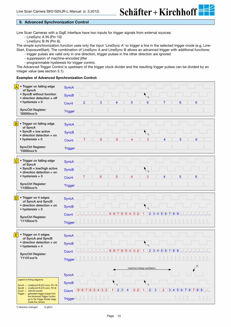
• Triggeronfallingedge ofSyncA• SyncBwithoutfunction• directiondetection=off• hysteresis=0
SyncCtrlRegister:'00000xxx'b
9. Advanced Synchronization Control
Line Scan Cameras with a GigE interface have two inputs for trigger signals from external sources:- LineSync A IN (Pin 10)- LineSync B IN (Pin 6).
The simple synchronization function uses only the input 'LineSync A' to trigger a line in the selected trigger mode (e.g, Line-Start, ExposureStart). The combination of LineSync A and LineSync B allows an advanced trigger with additional functions:
- trigger pulses are valid only in one direction, trigger pulses in the other direction are ignored- suppression of machine-encoded jitter- programmable hysteresis for trigger control.
The Advanced Trigger Control is upstream of the trigger clock divider and the resulting trigger pulses can be divided by an integer value (see section 5.1).
Examples of Advanced Synchronization Control:
A
• Triggeronfallingedge ofSyncA• SyncB=lowactive• directiondetection=on• hysteresis=0
SyncCtrlRegister:'10000xxx'b
B
• Triggeronfallingedge ofSyncA• SyncB=low/highactive• directiondetection=on• hysteresis=0
SyncCtrlRegister:'11000xxx'b
C
• Triggeron4edges ofSyncAandSyncB• directiondetection=on• hysteresis=0
SyncCtrlRegister:'11100xxx'b
D
• Triggeron4edges ofSyncAandSyncB• directiondetection=on• hysteresis=4
SyncCtrlRegister:'11101xxx'b
E
1)
2)
1)
1)
1)
1)
1)1)
machine holdup oscillation
1) direction changed 2) glitch
Legend of timing diagrams:
SyncA = LineSyncA IN (I/O conn. Pin 10)SyncB = LineSyncA IN (I/O conn. Pin 6)Count = internal counterTrigger = generated trigger pulses from the Advanced Trigger Control go to the Trigger Divider stage inside the camera.
Page 14
Line Scan Camera SK5150VJR-L Manual (v. 3.2012)
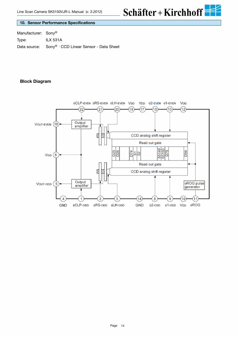
10. Sensor Performance Specifications
Manufacturer: Sony®
Type: ILX 531A
Data source: Sony® - CCD Linear Sensor - Data Sheet
Block Diagram
Page 15
Line Scan Camera SK5150VJR-L Manual (v. 3.2012)
Page 16
Line Scan Camera SK5150VJR-L Manual (v. 3.2012)
Page 17
Line Scan Camera SK5150VJR-L Manual (v. 3.2012)
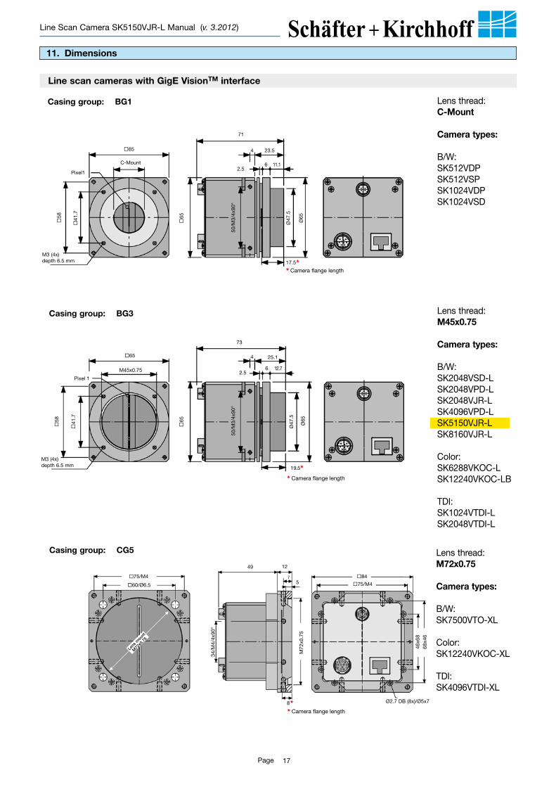
11. Dimensions
Casing group: BG1
* Camera flange length
* Camera flange length
Line scan cameras with GigE VisionTM interface
5
Ø2.7 DB (8x)/Ø5x7
7
Lens
moun
t
M72
x0.7
5
Pixel1
M3 (4x)depth 6.5 mm
65
65
2.56
4 23.5
17.5*
58
41
.7
Ø65
Ø47
.5
11.1C-Mount
50/M
3/4x
90°
49
75/M4
60/Ø6.5
84
75/M4
34/M
4/4x
90°
68x4
646
x68
M72
x0.7
5
12
8*
71
Lens thread: C-Mount
Camera types:
B/W:SK512VDPSK512VSPSK1024VDPSK1024VSD
Casing group: BG3
65
73
2.56
4 25.1
19.5*
Ø65
Ø47
.5
50/M
3/4x
90°
12.7
Pixel 1
M3 (4x)depth 6.5 mm
65
M45x0.75
58
41
.7
* Camera flange length
Casing group: CG5 Lens thread: M72x0.75
Camera types:
B/W:SK7500VTO-XL
Color:SK12240VKOC-XL
TDI:SK4096VTDI-XL
* Camera flange length
Lens thread: M45x0.75
Camera types:
B/W:SK2048VSD-LSK2048VPD-LSK2048VJR-LSK4096VPD-LSK5150VJR-LSK8160VJR-L
Color:SK6288VKOC-LSK12240VKOC-LB
TDI:SK1024VTDI-LSK2048VTDI-L
Page 18
Line Scan Camera SK5150VJR-L Manual (v. 3.2012)
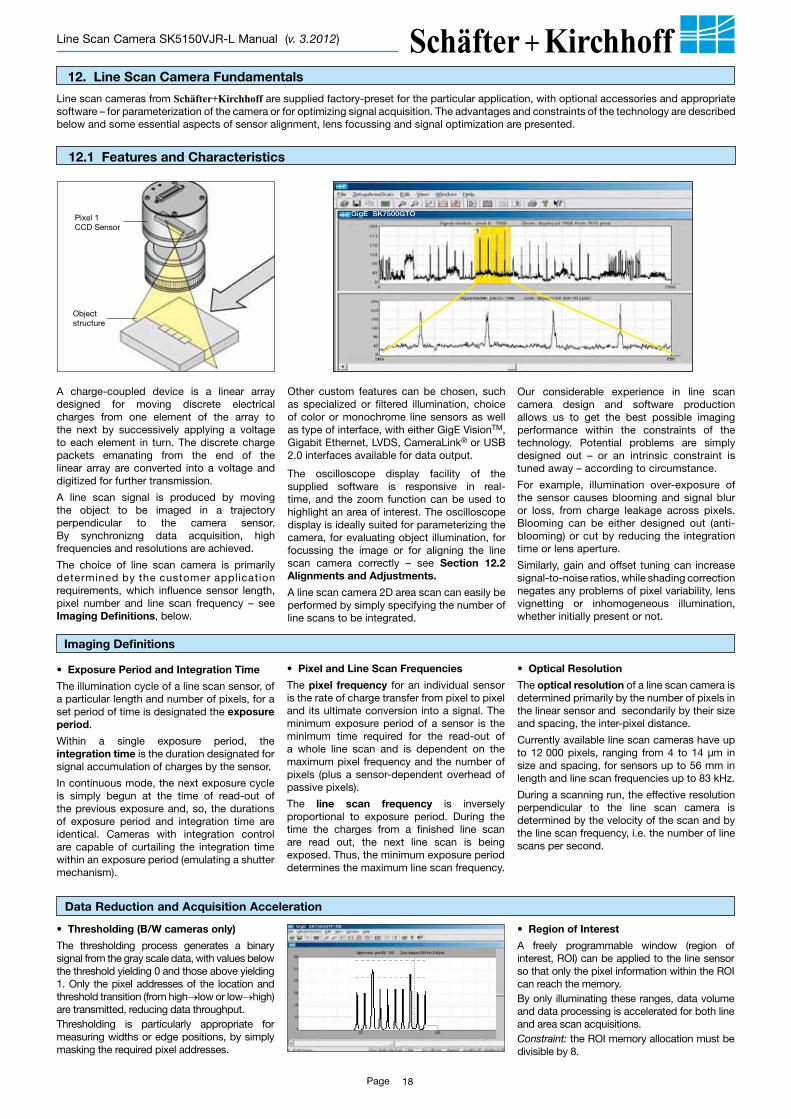
A charge-coupled device is a linear array designed for moving discrete electrical charges from one element of the array to the next by successively applying a voltage to each element in turn. The discrete charge packets emanating from the end of the linear array are converted into a voltage and digitized for further transmission.
A line scan signal is produced by moving the object to be imaged in a trajectory perpendicular to the camera sensor. By synchronizng data acquisition, high frequencies and resolutions are achieved.
The choice of line scan camera is primarily determined by the customer application requirements, which influence sensor length, pixel number and line scan frequency – see Imaging Definitions, below.
Our considerable experience in line scan camera design and software production allows us to get the best possible imaging performance within the constraints of the technology. Potential problems are simply designed out – or an intrinsic constraint is tuned away – according to circumstance.
For example, illumination over-exposure of the sensor causes blooming and signal blur or loss, from charge leakage across pixels. Blooming can be either designed out (anti-blooming) or cut by reducing the integration time or lens aperture.
Similarly, gain and offset tuning can increase signal-to-noise ratios, while shading correction negates any problems of pixel variability, lens vignetting or inhomogeneous illumination, whether initially present or not.
Other custom features can be chosen, such as specialized or filtered illumination, choice of color or monochrome line sensors as well as type of interface, with either GigE VisionTM, Gigabit Ethernet, LVDS, CameraLink® or USB 2.0 interfaces available for data output.
The oscilloscope display facility of the supplied software is responsive in real-time, and the zoom function can be used to highlight an area of interest. The oscilloscope display is ideally suited for parameterizing the camera, for evaluating object illumination, for focussing the image or for aligning the line scan camera correctly – see Section 12.2 Alignments and Adjustments.
A line scan camera 2D area scan can easily be performed by simply specifying the number of line scans to be integrated.
• Exposure Period and Integration Time
The illumination cycle of a line scan sensor, of a particular length and number of pixels, for a set period of time is designated the exposure period.
Within a single exposure period, the integration time is the duration designated for signal accumulation of charges by the sensor.
In continuous mode, the next exposure cycle is simply begun at the time of read-out of the previous exposure and, so, the durations of exposure period and integration time are identical. Cameras with integration control are capable of curtailing the integration time within an exposure period (emulating a shutter mechanism).
• Pixel and Line Scan Frequencies
The pixel frequency for an individual sensor is the rate of charge transfer from pixel to pixel and its ultimate conversion into a signal. The minimum exposure period of a sensor is the minimum time required for the read-out of a whole line scan and is dependent on the maximum pixel frequency and the number of pixels (plus a sensor-dependent overhead of passive pixels).
The line scan frequency is inversely proportional to exposure period. During the time the charges from a finished line scan are read out, the next line scan is being exposed. Thus, the minimum exposure period determines the maximum line scan frequency.
• Optical Resolution
The optical resolution of a line scan camera is determined primarily by the number of pixels in the linear sensor and secondarily by their size and spacing, the inter-pixel distance.
Currently available line scan cameras have up to 12 000 pixels, ranging from 4 to 14 µm in size and spacing, for sensors up to 56 mm in length and line scan frequencies up to 83 kHz.
During a scanning run, the effective resolution perpendicular to the line scan camera is determined by the velocity of the scan and by the line scan frequency, i.e. the number of line scans per second.
Imaging Definitions
12. Line Scan Camera Fundamentals
12.1 Features and Characteristics
Pixel 1CCD Sensor
Objectstructure
GigESK7500GTO
Line scan cameras from Schäfter+Kirchhoff are supplied factory-preset for the particular application, with optional accessories and appropriate software – for parameterization of the camera or for optimizing signal acquisition. The advantages and constraints of the technology are described below and some essential aspects of sensor alignment, lens focussing and signal optimization are presented.
• Region of Interest
A freely programmable window (region of interest, ROI) can be applied to the line sensor so that only the pixel information within the ROI can reach the memory. By only illuminating these ranges, data volume and data processing is accelerated for both line and area scan acquisitions. Constraint: the ROI memory allocation must be divisible by 8.
Data Reduction and Acquisition Acceleration
• Thresholding (B/W cameras only)
The thresholding process generates a binary signal from the gray scale data, with values below the threshold yielding 0 and those above yielding 1. Only the pixel addresses of the location and threshold transition (from high→low or low→high) are transmitted, reducing data throughput.Thresholding is particularly appropriate for measuring widths or edge positions, by simply masking the required pixel addresses.
GigESK7500GTF-XB
Page 19
Line Scan Camera SK5150VJR-L Manual (v. 3.2012)
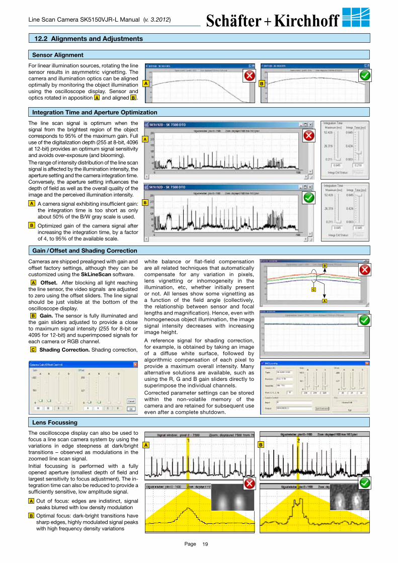
Integration Time and Aperture Optimization
The line scan signal is optimum when the signal from the brightest region of the object corresponds to 95% of the maximum gain. Full use of the digitalization depth (255 at 8-bit, 4096 at 12-bit) provides an optimum signal sensitivity and avoids over-exposure (and blooming). The range of intensity distribution of the line scan signal is affected by the illumination intensity, the aperture setting and the camera integration time. Conversely, the aperture setting influences the depth of field as well as the overall quality of the image and the perceived illumination intensity.
A A camera signal exhibiting insufficient gain: the integration time is too short as only about 50% of the B/W gray scale is used.
B Optimized gain of the camera signal after increasing the integration time, by a factor of 4, to 95% of the available scale.
B
A
Gain / Offset and Shading Correction
white balance or flat-field compensation are all related techniques that automatically compensate for any variation in pixels, lens vignetting or inhomogeneity in the illumination, etc, whether initially present or not. All lenses show some vignetting as a function of the field angle (collectively, the relationship between sensor and focal lengths and magnification). Hence, even with homogeneous object illumination, the image signal intensity decreases with increasing image height.
A reference signal for shading correction, for example, is obtained by taking an image of a diffuse white surface, followed by algorithmic compensation of each pixel to provide a maximum overall intensity. Many alternative solutions are available, such as using the R, G and B gain sliders directly to superimpose the individual channels. Corrected parameter settings can be stored within the non-volatile memory of the camera and are retained for subsequent use even after a complete shutdown.
A
B
C
Cameras are shipped prealigned with gain and offset factory settings, although they can be customized using the SkLineScan software.
A Offset. After blocking all light reaching the line sensor, the video signals are adjusted to zero using the offset sliders. The line signal should be just visible at the bottom of the oscilloscope display. B Gain. The sensor is fully illuminated and the gain sliders adjusted to provide a close to maximum signal intensity (255 for 8-bit or 4095 for 12-bit) and superimposed signals for each camera or RGB channel.
C Shading Correction. Shading correction,
Lens Focussing
The oscilloscope display can also be used to focus a line scan camera system by using the variations in edge steepness at dark/bright transitions – observed as modulations in the zoomed line scan signal. Initial focussing is performed with a fully opened aperture (smallest depth of field and largest sensitivity to focus adjustment). The in-tegration time can also be reduced to provide a sufficiently sensitive, low amplitude signal.
A Out of focus: edges are indistinct, signal peaks blurred with low density modulation
B Optimal focus: dark-bright transitions have sharp edges, highly modulated signal peaks with high frequency density variations
BA
12.2 Alignments and Adjustments
Sensor Alignment
For linear illumination sources, rotating the line sensor results in asymmetric vignetting. The camera and illumination optics can be aligned optimally by monitoring the object illumination using the oscilloscope display. Sensor and optics rotated in apposition A and aligned B .
A B
Kieler Str. 212, 22525 Hamburg, Germany • Tel: +49 40 85 39 97-0 • Fax: +49 40 85 39 97-79 • [email protected] • www.SuKHamburg.de
SK
5150
VJR
-LLine Scan Camera SK5150VJR-L Manual (v. 3.2012)
Lenses:• high resolution enlarging and macro lenses • high speed photo lenses• lenses with additional locking bridge for locking of
focus and aperture setting
Adapter:Lens adapter AOC-...• for fitting photo lenses onto the CCD line scan
cameraFocus adapter FA22-...• for fitting enlarging or macro lenses
Mounting bracket SK5105-L Order CodeWarp-resistant construction for the mounting of the CCD line scan camera
Clamp set SK5101 Order Code to lock the CCD line scan camera in desired position
CAT6 network cable Shielded CAT6 patch cable, halogen-free, both ends with RJ45 connectors for Gigabit Ethernet
CAT6.3 Order Code 3 = 3 m cable length 5 = 5 m (standard) x = length of choice (up to 100 m)
Cable for external synchro nization BNC coaxial cable with Hirose connector HR10A, female 12-pin
SK9024.3 Order Code 3 = 3 m cable length 5 = 5 m (standard) x = length of choice
Power supply cable SK9015... Shielded cable with male 6-pin Lumberg SV60 and female 6-pin Hirose HR10A connectors
SK9015.1.5-MF Order Code MF = connector (male/female) 0.2 = 0.2 m cable length 1.5 = 1.5 m (standard)
Power Supply: PS051515 Order CodeInput: 100–240 V AC, 50/60 Hz, 0.8 A 3-pin input connection (IEC 320)Output: 5 V DC/2.5 A 15 V DC/0.5 A, -15 V DC/0.3 A output connector: Lumberg KV60, female 6-pin, length 1 m
Software: SK91GigE-WIN * Order CodeSkLineScan operating program for camera control.SDK with examples, DLLs and C++ class library.
* Windows 7 (32/64 bit) / Vista (32/64) / XP
SkGEVTool
13. Warranty
EC Declaration of Conformity
This product satisfies the requirements of the EC directive 89/336/EEG as well as DIN EN 61326.
This manual has been prepared and reviewed as carefully as possible but no warranty is given or implied for any errors of fact or in interpretation that may arise. If an error is suspected then the reader is kindly requested to inform us for appropriate action.
The circuits, descriptions and tables may be subject to and are not meant to infringe upon the rights of a third party and are provided for informational purposes only.
The technical descriptions are general in nature and apply only to an assembly group. A particular feature set, as well as its suitability for a particular purpose, is not guaranteed.
The warranty period for the CCD line scan camera when used for the purpose for which it was intended is 24 months.
The warranty is immediately void on inappropriate modification, use or damage.
14. Accessories


![OUTPERFORM [V] INITIATION](https://static.fdocuments.in/doc/165x107/6189e5c61eda5f71d25deb98/outperform-v-initiation.jpg)