Monobloc and Sectional Directional Control Valves · Monobloc and Sectional Directional Control...
19
1/220 200 − P − 991210 − E − 03 / 10.04 Monobloc and Sectional Directional Control Valves 200-P-991210-EN-03/09.2015
-
Upload
truongdiep -
Category
Documents
-
view
250 -
download
0
Transcript of Monobloc and Sectional Directional Control Valves · Monobloc and Sectional Directional Control...
1/220200 − P − 991210 − E − 03 / 10.04
Monobloc and Sectional Directional Control Valves
200-P-991210-EN-03/09.2015
HDM18
48/220200 − P − 991210 − E − 03 / 10.04
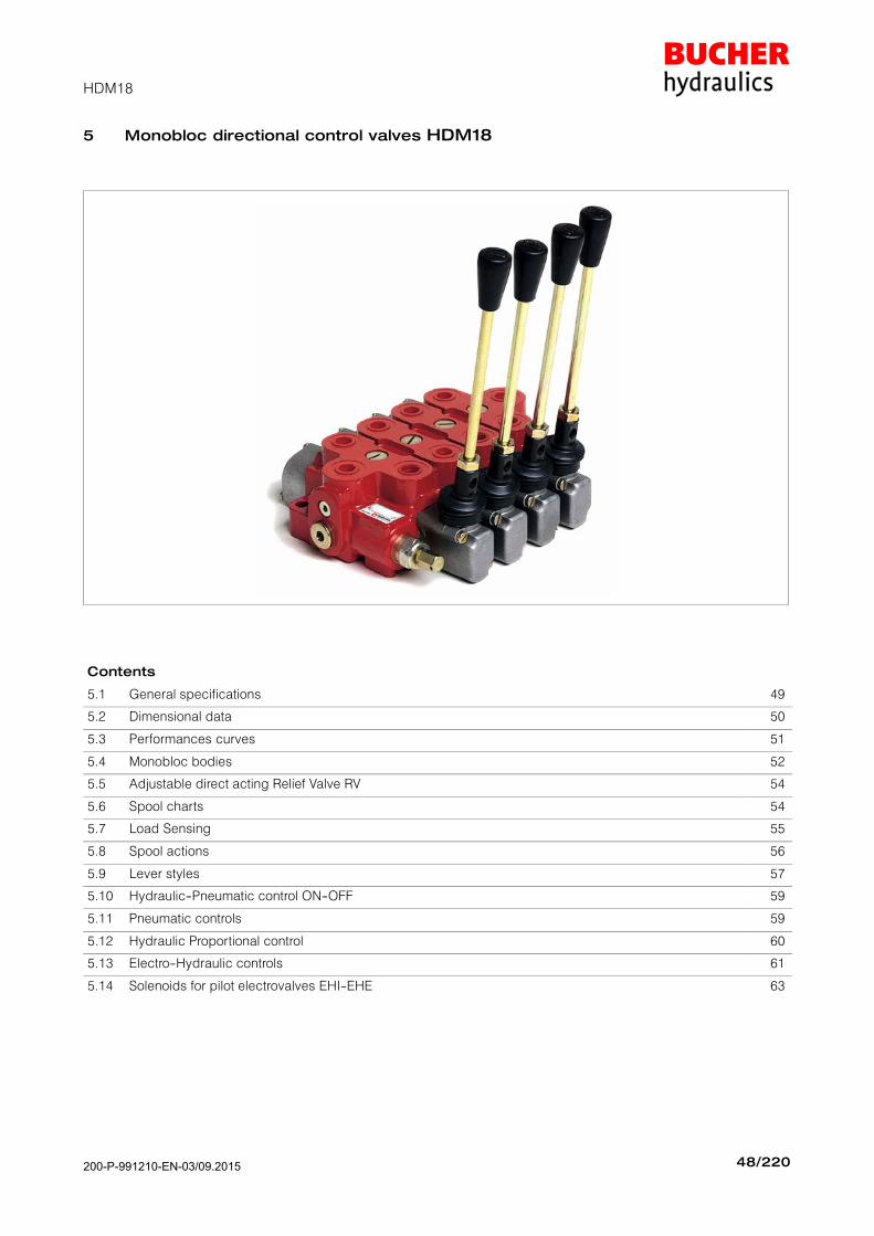
5 Monobloc directional control valves HDM18
Contents
5.1 General specifications 49
5.2 Dimensional data 50
5.3 Performances curves 51
5.4 Monobloc bodies 52
5.5 Adjustable direct acting Relief Valve RV 54
5.6 Spool charts 54
5.7 Load Sensing 55
5.8 Spool actions 56
5.9 Lever styles 57
5.10 Hydraulic−Pneumatic control ON−OFF 59
5.11 Pneumatic controls 59
5.12 Hydraulic Proportional control 60
5.13 Electro−Hydraulic controls 61
5.14 Solenoids for pilot electrovalves EHI−EHE 63
200-P-991210-EN-03/09.2015

HDM18
49/220200 − P − 991210 − E − 03 / 10.04
5.1 General specifications
Technical specification
Max flow ratel/min.
U.S.G.P.M.7018
Max continuous operatingpressure supply port P
barPSI
3505000
Max intermittent peak pres-sure Work port A/B
barPSI
4005800
Max back pressuretank port T
barPSI
30430
Oil temperature° C° F
−10 to 8014 to 180
Oil viscosity mm2/s 16 to 75
Oil filtration 30
Spool leakage at 100 bar (1450 PSI), Temp. 50° C (120° F), viscosity 27 mm2/s:
Maximumcm3/min.
Cu. In./min.14
0.854
Averagecm3/min.
Cu. In./min.7
0.427
Lower values on demand (to be agreed with our Sales Dept.)
Number of spools 1 to 4
Adjustable direct operated relief valve(tamper−proof seal available on request)
RV
Load hold check valve in each section LC
5.1.1 Weight
Version kg lb
HDM18/1 4.3 9.60
HDM18/2 6.0 13.2
HDM18/3 9.0 19.8
HDM18/4 12.0 26.4
5.1.2 Material specification:
Body: High strength cast−iron.Spool: Hardened steel and chrome platedSeals: Buna N".
5.1.3 Standard features:
1) Parallel circuit2) Balanced interchangeable spools (provides
minimum leakage, smooth operation)3) Wide selection inlets, work ports, and outlets
threaded ports.4) Negative overlapping of the spool.
5.1.4 Optional features available:
1) Open or closed centre positions, 3 or 4 way operations, 3 or 4 position (float position), full
open centre (motor spool) and other spooloptions.
2) Carry over.3) Series circuit4) Load Sensing circuit closed centre for variable
displacement pump5) Complete lever assembly6) Wide range of positioners
5.1.5 Symbols:
P: inlet portT: outlet portA/B: work portsH.P.C.O.: carry−overRV: relief valveP1T1: side inlet and outlet ports3.1.0.2: spool positionP: pressure lineT : exhaust lineE: centre line (by pass).
200-P-991210-EN-03/09.2015

HDM18
50/220200 − P − 991210 − E − 03 / 10.04
5.2 Dimensional data
Ex.: 115 = mm
4.53" = inches
HDM18/1
HDM18/2/3/4
Pos.2: STROKE − 5 mm. − .19"
Pos.1: STROKE − 5 mm. − .19"
Pos.3: STROKE − 9 mm. − .35"PRESS
PRESS
B
A
0
Float
RV
P1
A
B
TP
B
AA
B
TP
Pos.2: STROKE − 5 mm. − .19"0Pos.1: STROKE − 5 mm. − .19"
B
A
RV
P1
T1 H.P.C.O.
SAE14
(1"−3/16−12 UNF)
(see 5.9)
Dimensional data shown in mm and inches
75
2.9
5"
Identification
plate
PRESS
PRESS
N. of sections HDM18/2 HDM18/3 HDM18/4
n A115 155 195
en
sio
n A4.53" 6.11" 7.69"
Dim
en
B155 195 235
D B6.11" 7.69" 9.25"
200-P-991210-EN-03/09.2015

HDM18
51/220200 − P − 991210 − E − 03 / 10.04
5.3 Performance curves
Oil: Shell Tellus T37Temperature: 50° C (120° F)Viscosity: 27 mm2/s
Flow rate
l/min
bar
Pre
ssu
re d
rop
U.S.G.P.M.
PSI
P ⇒ T
std. Spools
Metering
Flow rate
l/min
bar
Pre
ssu
re d
rop
U.S.G.P.M.
PSI
Flow rate
l/min
bar
Pre
ssu
re d
rop
U.S.G.P.M.
PSI
A/B ⇒ T
P ⇒ A/B
Stroke
A/B → T 150 bar
inches
mm
l/min
A/B → T 50 barP → A/B 50 bar
P → A/B 150 bar
Flo
w r
ate
U.S
.G.P
.M.
200-P-991210-EN-03/09.2015
HDM18
52/220200 − P − 991210 − E − 03 / 10.04
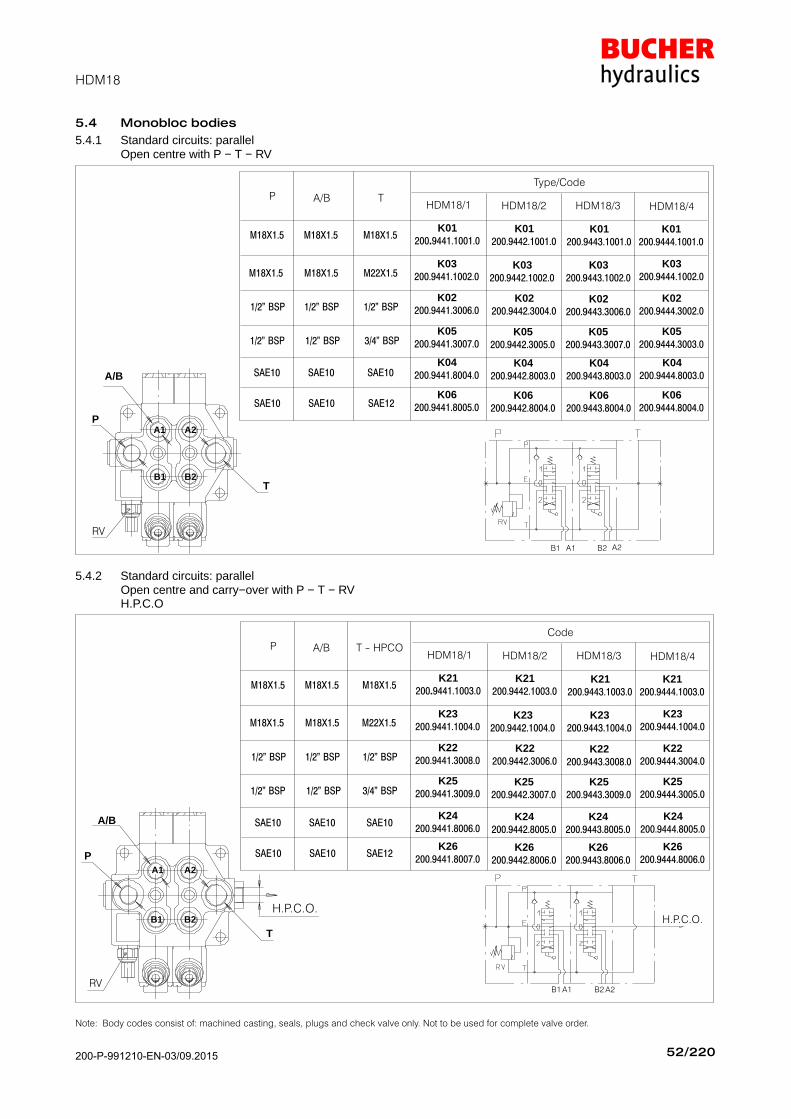
5.4 Monobloc bodies
5.4.1 Standard circuits: parallelOpen centre with P − T − RV
Type/Code
SAE10
M18X1.5
1/2" BSP
SAE10
HDM18/1 HDM18/2 HDM18/3 HDM18/4
1/2" BSPK05
200.9442.3005.0
K01200.9441.1001.0
K05200.9441.3007.0
K02200.9441.3006.0
K03200.9441.1002.0
K01200.9442.1001.0
K02200.9442.3004.0
K03200.9442.1002.0
K01200.9443.1001.0
K05200.9443.3007.0
K02200.9443.3006.0
K03200.9443.1002.0
K01200.9444.1001.0
K05200.9444.3003.0
K02200.9444.3002.0
K03200.9444.1002.0M18X1.5
SAE10
M18X1.5
1/2" BSP
SAE10
1/2" BSP
M18X1.5
SAE10
M18X1.5
1/2" BSP
SAE12
3/4" BSP
M22X1.5
K04200.9442.8003.0
K04200.9441.8004.0
K04200.9443.8003.0
K04200.9444.8003.0
K06200.9442.8004.0
K06200.9441.8005.0
K06200.9443.8004.0
K06200.9444.8004.0
A/B TP
P
T
RV
A/B
A1 A2
B2B1
A1B1 B2 A2
5.4.2 Standard circuits: parallelOpen centre and carry−over with P − T − RVH.P.C.O
P
T
RV
H.P.C.O.
A/B
H.P.C.O.
Code
SAE10
M18X1.5
1/2" BSP
SAE10
HDM18/1 HDM18/2 HDM18/3 HDM18/4
1/2" BSPK25
200.9442.3007.0
K21200.9441.1003.0
K25200.9441.3009.0
K22200.9441.3008.0
K23200.9441.1004.0
K21200.9442.1003.0
K22200.9442.3006.0
K23200.9442.1004.0
K21200.9443.1003.0
K25200.9443.3009.0
K22200.9443.3008.0
K23200.9443.1004.0
K21200.9444.1003.0
K25200.9444.3005.0
K22200.9444.3004.0
K23200.9444.1004.0M18X1.5
SAE10
M18X1.5
1/2" BSP
SAE10
1/2" BSP
M18X1.5
SAE10
M18X1.5
1/2" BSP
SAE12
3/4" BSP
M22X1.5
K24200.9442.8005.0
K24200.9441.8006.0
K24200.9443.8005.0
K24200.9444.8005.0
K26200.9442.8006.0
K26200.9441.8007.0
K26200.9443.8006.0
K26200.9444.8006.0
A/B T − HPCOP
A1B1 A2B2
A1 A2
B2B1
Note: Body codes consist of: machined casting, seals, plugs and check valve only. Not to be used for complete valve order.
200-P-991210-EN-03/09.2015
HDM18
53/220200 − P − 991210 − E − 03 / 10.04
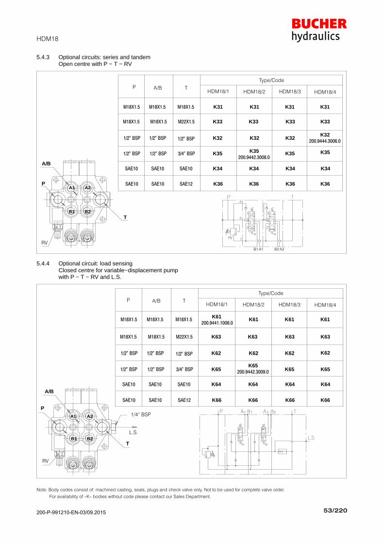
5.4.3 Optional circuits: series and tandemOpen centre with P − T − RV
P
T
RV
A/B
Type/Code
SAE10
M18X1.5
1/2" BSP
SAE10
HDM18/1 HDM18/2 HDM18/3 HDM18/4
1/2" BSPK35
200.9442.3008.0
K31
K35
K32
K33
K31
K32
K33
K31
K35
K32
K33
K31
K35
K32200.9444.3006.0
K33M18X1.5
SAE10
M18X1.5
1/2" BSP
SAE10
1/2" BSP
M18X1.5
SAE10
M18X1.5
1/2" BSP
SAE12
3/4" BSP
M22X1.5
K34K34 K34 K34
K36K36 K36 K36
A/B TP
A1 A2
B2B1
A1B1 A2B2
5.4.4 Optional circuit: load sensingClosed centre for variable−displacement pumpwith P − T − RV and L.S.
P
T
RV
L.S.
1/4" BSP
A/B
Type/Code
SAE10
M18X1.5
1/2" BSP
SAE10
HDM18/1 HDM18/2 HDM18/3 HDM18/4
1/2" BSPK65
200.9442.3009.0
K61 200.9441.1006.0
K65
K62
K63
K61
K62
K63
K61
K65
K62
K63
K61
K65
K62
K63M18X1.5
SAE10
M18X1.5
1/2" BSP
SAE10
1/2" BSP
M18X1.5
SAE10
M18X1.5
1/2" BSP
SAE12
3/4" BSP
M22X1.5
K64K64 K64 K64
K66K66 K66 K66
A/B TP
A1 A2
B2B1
Note: Body codes consist of: machined casting, seals, plugs and check valve only. Not to be used for complete valve order.
For availability of −K− bodies without code please contact our Sales Department.
200-P-991210-EN-03/09.2015

HDM18
54/220200 -- P -- 991210 -- E -- 03 / 10.04
5.5 Adjustable direct acting Relief Valve RV
06
15
26
60(860)
150(2100)
260(3700)
Yellow(YE)
Green(GR)
Blue(BL)
30 -- 95(400 -- 1300)
96 -- 210(1300 -- 3000)
211 -- 300(3000 -- 4200)
TypeStd. settingbar (PSI)
Spring colourPressure set range
(PSI)
Relief valve set at 30 l/min (8 U.S.G.P.M.)
Fluctuating pressure
Operating Time
Pea
k
P
T
Flow ratel/min
bar
Pre
ssur
ese
tting
U.S.G.P.M.
PSI
RV
32320
(4600)Red(RD)
301 -- 400(4200 -- 5700)
T
P
Set
ting
*
* The maximum operating pressure for each valve series is indicated in the
“Technical specification” at the first page of each valve section.
5.6 Spool charts
Spool scheme Spool features Type
4 way -- 3 positionA/B closed
E open by pass
AAS*
4 way -- 3 positionA/B--E closed B
4 way -- 3 positionA/B to tank in neutral
E open by pass
CCS*
4 way -- 3 positionA closed
B to tank in neutralD
3 way -- 3 positionB closed
E open by pass
GGS*
4 way -- 3 positionB closed
A to tank in neutralL
4 way -- 3 position withdifferential spool in 2nd
positionR**
3 way -- 3 positionA closed
E open by pass
SSS*
4 way -- 3 positionseries connection
XXS*
4 way -- 3 positionA/B to tank in neutral
series connectionXC
4 way -- 4 position4th float position
ZZS*
4 way -- 3 positionA/B closed
Load Sensing
**LSA
4 way -- 3 positionA/B to tank in neutral
Load Sensing
**LSC
3way -- 3 positionB closed
Load Sensing
**LSG
3 way -- 3 positionA closed
Load Sensing
**LSS
** : special body required
* : High metering spool (max. flow suggested 40 l/min)
Note: For availability of L/S versions please contact our Sales Department
200-P-991210-EN-03/09.2015
HDM18
55/220200 − P − 991210 − E − 03 / 10.04
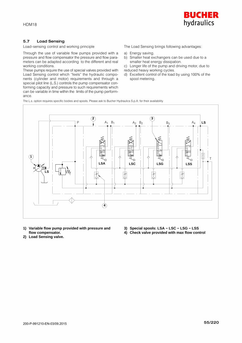
5.7 Load Sensing
Load−sensing control and working principle
Through the use of variable flow pumps provided with apressure and flow compensator the pressure and flow para-meters can be adapted according to the different and realworking conditions.These pumps require the use of special valves provided withLoad Sensing control which feels" the hydraulic compo-nents (cylinder and motor) requirements and through aspecial pilot line (L.S.) controls the pump compensator con-forming capacity and pressure to such requirements whichcan be variable in time within the limits of the pump perform-ance.
The Load Sensing brings following advantages:
a) Energy saving.b) Smaller heat exchangers can be used due to a
smaller heat energy dissipation.c) Longer life of the pump and driving motor, due toreduced heavy working cycles.d) Excellent control of the load by using 100% of the
spool metering.
The L.s. option requires specific bodies and spools. Please ask to Bucher Hydraulics S.p.A. for their availability
LSCLSA LSG LSS
P A1 B1 A2 B2 B3 A4
T
LS
LS
1
2 3
4
1) Variable flow pump provided with pressure and flow compensator.
2) Load Sensing valve.
3) Special spools: LSA − LSC − LSG − LSS4) Check valve provided with max flow control
200-P-991210-EN-03/09.2015

HDM18
56/220200 − P − 991210 − E − 03 / 10.04
5.8 Spool positioners
Spool position StrokeType Code
3 1 0 2 mmType Code
5 08 200.9686.1008.0
5 10 200.9686.3004.0
5 17 200.9686.2014.0
5 20 200.9686.3009.0
5 25 200.9686.2015.0
10 27 200.9686.1044.0
5 29 200.9686.3025.0
5 30 200.9686.1048.0
5 32 200.9686.1061.0
5 34 200.9686.1065.0
10 36 200.9686.2017.0
10 37 200.9686.1066.0
5 38 200.9686.1069.0
5 79 200.9686.1091.0
5 84 200.9686.1098.0
5 133 200.9686.1031.0
4− 5− 5 136 200.9686.4012.0
Initial hand lever position Hand lever in detent position Spring return position of hand lever
Spool position corresponds tohand lever position
F (N)= Force in Newton (N) needed to operate the spool
F (N) Spool position control
260 08
130 79
190133
(standard)
Note: consult factory for different configurations.
5.8.1 Spool positioners dimensions
Spool positioners08 − 38 − 79 − 133
Spool positioners10 − 17 − 20 − 25 − 27
29 − 36 − 37
Spool positioner(Z spool type)
136
Spool positioner84
5.8.2 Microswitch control
Microswitch is operated when the spool is in pos.1
Microswitch is operated when the spool is in pos.2
Microswitch is operated when the spool is in pos.1and 2 The microswitch is supplied only on
customer’s request.
Type30
Type32
Type34
200-P-991210-EN-03/09.2015
HDM18
57/220200 − P − 991210 − E − 03 / 10.04
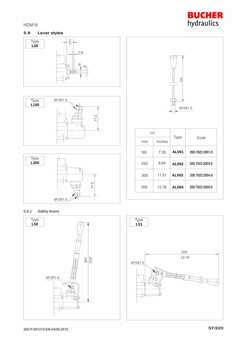
5.9 Lever styles
TypeL55
27
9
816
TypeL100
M10X1.5
71
.5
TypeL300
M10X1.5
71
.5
AL001
AL004
AL003
AL002
185 7.28
9.84
11.81
13.78350
300
250
200.7022.2001.0
200.7022.2003.0
200.7022.2004.0
200.7022.2005.0
mm inches
LoType Code
Lo
M10X1.5
5.9.1 Safety levers
TypeL50
M10X1.5
30
7
12
.9"
335
13.19"
M10X1.5
TypeL51
200-P-991210-EN-03/09.2015

HDM18
58/220200 − P − 991210 − E − 03 / 10.04
5.9.2 Remote cable control
LeverSupport
Code200.7609.0013.0
M10X1.5
Optional
200.6772.0048.0
Cables are assembled on the
valve only on request and
with an extra charge.
Cable
200.5441.04002
200.5441.04005
200.5441.04006
200.5441.04007
200.5441.04008200.5441.04009
Cablelength Code
1000 mm1500 mm2000 mm2500 mm3000 mm4000 mm
M10X1.5
L0 AL001
AL004
AL003
AL002
185 7.28
9.84
11.81
13.78350
300
250
200.7022.2001.0
200.7022.2003.0
200.7022.2004.0
200.7022.2005.0
mm inches
LoType Code
Spool Kit
Code 200.9609.0001.0
Optional
200.6772.0048.0
TypeL142
Code200.7071.2012.0
Only for rod remote control
M10X1.5
5.9.3 Cross joystick for dual axis spool control
M12X1.75
TypeAL010
Code200.7022.3004.0
Lo
=2
50
TypeL133
Code200.9759.3009.0
Fulcrum
.
Fulcrum
Type
L134Code
200.9759.3009.0
Fulcrum
Stick Lever
M12X1.75(AL010)
Spool
A
A
B
B
P
T
Spool
Stick Lever
M12X1.75
Fulcrum
(AL010)
L133−L134 are supplied
complete with rubber boot
protection
X
X
X
View from X
View from X
200-P-991210-EN-03/09.2015
HDM18
59/220200 − P − 991210 − E − 03 / 10.04
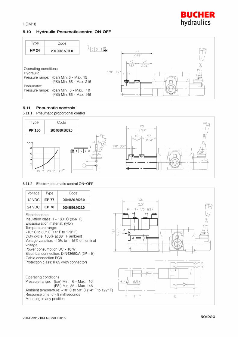
5.10 Hydraulic−Pneumatic control ON−OFF
Type Code
HP 24 200.9686.5011.0
Operating conditionsHydraulic:Pressure range: (bar) Min. 6 − Max. 15
(PSI) Min. 85 − Max. 215Pneumatic:Pressure range: (bar) Min. 6 − Max. 10
(PSI) Min. 85 − Max. 145
5.11 Pneumatic controls
5.11.1 Pneumatic proportional control
Type Code
PP 150 200.9686.5009.0
5.11.2 Electro−pneumatic control ON−OFF
Electrical dataInsulation class H − 180° C (356° F)Encapsulation material: nylonTemperature range:−10° C to 80° C (14° F to 170° F)Duty cycle: 100% at 68° F ambientVoltage variation: −10% to + 15% of nominalvoltage
Power consumption DC − 10 WElectrical connection: DIN43650/A (2P + E)Cable connection PG9Protection class: IP65 (with connector)
Operating conditionsPressure range: (bar) Min. 6 − Max. 10
(PSI) Min. 85 − Max. 145Ambient temperature: −10° C to 50° C (14° F to 122° F)Response time: 6 − 8 millisecondsMounting in any position
EP 77
Type
12 VDC 200.9686.6023.0
EP 78
Voltage Code
200.9686.6026.024 VDC
200-P-991210-EN-03/09.2015
HDM18
60/220200 − P − 991210 − E − 03 / 10.04
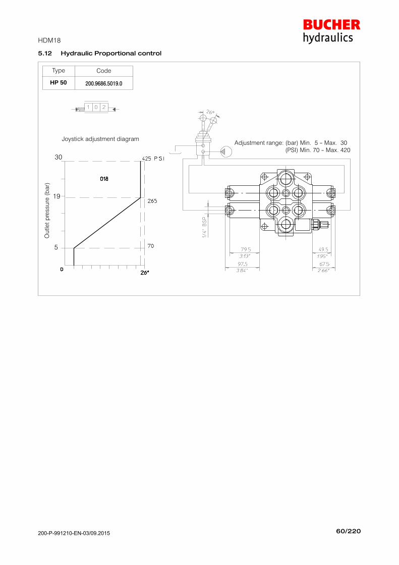
5.12 Hydraulic Proportional control
Joystick adjustment diagram
Type Code
HP 50 200.9686.5019.0
Ou
tle
t p
ressu
re (
ba
r)
30
19
5
Adjustment range: (bar) Min. 5 − Max. 30 (PSI) Min. 70 − Max. 420
200-P-991210-EN-03/09.2015

HDM18
61/220200 − P − 991210 − E − 03 / 10.04
5.13 Electro−Hydraulic controls
5.13.1 Electro−hydraulic control internal pilot version ON−OFF with pressure reducing valve
Pressure reducing valve
VCP Return back pressure valve
(T2 = 1/2" BSP) code 200.7874.0157.0(to order separately)
p min= 10 bar
(145 PSI)
p max= 15 bar
(215 PSI)
VCP
For solenoid see chapter 5.14
Type Code
EHI 263* 200.9686.6038.0
Mechanical and hydraulic features
Max pressure on Pp port 300 bar (4200 PSI). . . . . . . . . . . . Reduced pressure afterpressure reducing valve 10 bar (145 PSI). . . . . . . . . . . . . . . Fixed delivery on Pppilot line 1 l/min (0.26 U.S.G.P.M). . . . . . . . . . . . . . . . . . . . . .
* EHI 263: special body required.
Leakage of pressure reducingvalve (in neutral pos.) 100 ml/min ( 6.1 in3/min ). . . . . . . . . Min. suggested filtration 25 micron. . . . . . . . . . . . . . . . . . . . Operating oil temperature min.−30°C− max. 90°C. . . . . . . .
min.−22°F − max 194°F. . . . . . . . . . . . . . . . . . . . . . . . . . . . . .
200-P-991210-EN-03/09.2015

HDM18
62/220200 − P − 991210 − E − 03 / 10.04
5.13.2 Electro−hydraulic controls external pilot version ON−OFF
EHE 300
Type
Inlet section 200.9686.6042.0
EHE 304
Description Code
200.9686.6034.0Intermediate section
EHE 305End section 200.9686.6036.0
For solenoid see
chapter 5.14
5.13.3 Electro−hydraulic control external pilot versionON−OFF with pressure reducing valve on inletmanifold
EHE 302
Type
Inlet section 200.9686.6031.0
Description Code
For solenoid see
chapter 5.14
Mechanical and hydraulic features
Pilot pressure min. 10 bar (140 PSI). . . . . . . . . . . . . . . . . . . . Pilot pressure max. 30 bar (420 PSI). . . . . . . . . . . . . . . . . . . Pilot pressure with pressurereducing valve 12 bar (175 PSI). . . . . . . . . . . . . . . . . . . . . . . Pilot flow to each workingsection 1 l/min (0.26 U.S.G.P.M.). . . . . . . . . . . . . . . . . . . . . . .
Operating oil temperature min.−30°C− max. 90°C. . . . . . . . min.−22°F − max 194°F. . . . . . . . . . . . . . . . . . . . . . . . . . . . . .
Leakage of pressure reducingvalve (in neutral pos.) 100 ml/min (6.1 in3/min). . . . . . . . . . Min. suggested filtration 25 micron. . . . . . . . . . . . . . . . . . . .
200-P-991210-EN-03/09.2015
HDM18
63/220200 − P − 991210 − E − 03 / 10.04
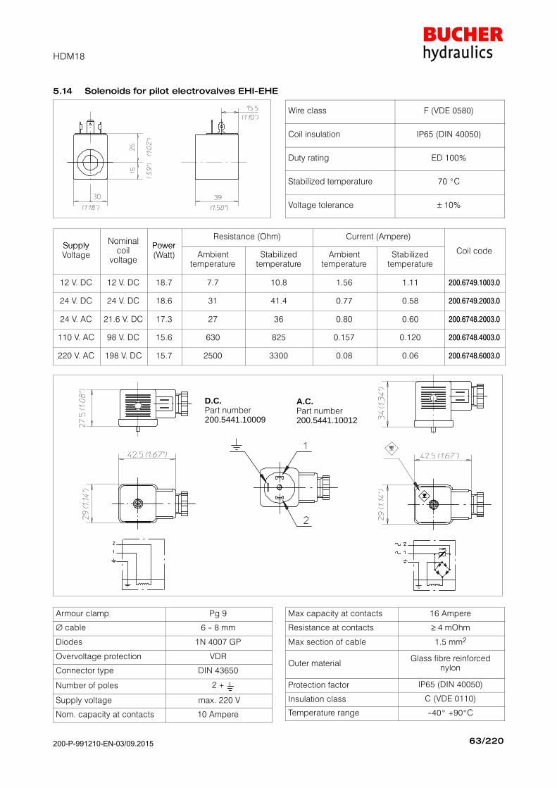
5.14 Solenoids for pilot electrovalves EHI−EHE
Wire class F (VDE 0580)
Coil insulation IP65 (DIN 40050)
Duty rating ED 100%
Stabilized temperature 70 C
Voltage tolerance ± 10%
SupplyNominal
PowerResistance (Ohm) Current (Ampere)
SupplyVoltage
Nominalcoil
voltage
Power(Watt) Ambient
temperatureStabilized
temperatureAmbient
temperatureStabilized
temperature
Coil code
12 V. DC 12 V. DC 18.7 7.7 10.8 1.56 1.11 200.6749.1003.0
24 V. DC 24 V. DC 18.6 31 41.4 0.77 0.58 200.6749.2003.0
24 V. AC 21.6 V. DC 17.3 27 36 0.80 0.60 200.6748.2003.0
110 V. AC 98 V. DC 15.6 630 825 0.157 0.120 200.6748.4003.0
220 V. AC 198 V. DC 15.7 2500 3300 0.08 0.06 200.6748.6003.0
D.C.Part number200.5441.10009
A.C.Part number200.5441.10012
Armour clamp Pg 9
∅ cable 6 − 8 mm
Diodes 1N 4007 GP
Overvoltage protection VDR
Connector type DIN 43650
Number of poles 2 +
Supply voltage max. 220 V
Nom. capacity at contacts 10 Ampere
Max capacity at contacts 16 Ampere
Resistance at contacts ≥ 4 mOhm
Max section of cable 1.5 mm2
Outer materialGlass fibre reinforced
nylon
Protection factor IP65 (DIN 40050)
Insulation class C (VDE 0110)
Temperature range −40 +90C
200-P-991210-EN-03/09.2015

HDM18
64/220200 − P − 991210 − E − 03 / 10.04
5.15 Electromagnetic controls ON−OFF
+
EPP 344*
Type
12 VDC 200.9686.1179.0
EPP 343*
Voltage Code
200.9686.1180.024 VDC
* special body requaired
155
6.10"
89
.5
3.5
2"
2.1
3"
54
59
2.32"
2 1 1 3
2
3
1
.
1 / 31 / 2
1 32
A=1−3
PUSH
B=1−2
PULL
AB+ +
−
To be used with special spools only: the spool definition isdifferent from the standard one because of the double P". For example A spool become AP3.Ex.: (A spool + 24 VDC positioner)= AP3343
Mechanical and hydraulic features
Max operating pressure 150 bar (2800 PSI). . . . . . . . . . . . Max flow 40 l/min (15 U.S.G.P.M.). . . . . . . . . . . . . . . . . . . . . Max back pressure 5 bar (70 PSI). . . . . . . . . . . . . . . . . . . . . Operating oil temperature 80 C (180 F). . . . . . . . . . . . . . .
Electromagnetic specification
Input tension 12 V DC [24 V DC] ± 10%. . . . . . . . . . . . . . . . Power consumption 60 W. . . . . . . . . . . . . . . . . . . . . . . . . . . . ED: 100 %. . . . . . . . . . . . . . . . . . . . . . . . . . . . . . . . . . . . . . . . .
Ohms resistance (cold T): 2.4 Ω [9.6 Ω]. . . . . . . . . . . . . . . Ohms resistance (stabilized T): 3.1 Ω [12.5 Ω]. . . . . . . . . Intensity of current (cold T) 5 A (2.5 A). . . . . . . . . . . . . . . . Intensity of current (stabilized T) 3.8 A (1.9 A). . . . . . . . . Ambient operating temperature range: −25C/+60C. . . . Average stabilized coil temperature operated continuously +105C. . . . . . . . . . . . . . . . . . . . . . . . . . . . . . . . The above mentioned average temperature is obtainedwith a nominal voltage of 12 V (24 V), with an ambient tem-perature of 25 C and with an electromagnet assembledon an hydraulic valve with oil circulation.Insulation class:according to VDE 0580 standard H. . . . . . . . . . . . . . . . . . . Electrical connection:with Hirschmann connector per DIN 43650 IP 65. . . . . . . .
200-P-991210-EN-03/09.2015
200 − P − 991210 − E − 03 / 10.04
BUCHER HYDRAULICS www.bucherhydraulics.com
We reserve the right of modification without prior notice.
Germany
Phone +49 7742 85 20
Fax +49 7742 71 16
Switzerland
Phone +41 33 67 26 11 1
Fax +41 33 67 26 10 3
France
Phone +33 389 64 22 44
Fax +33 389 65 28 78
Italy
Phone +39 0522 92 84 11
Fax +39 0522 51 32 11
Austria
Phone +43 6216 44 97
Fax +43 6216 44 97 4
Netherlands
Phone +31 79 34 26 24 4
Fax +31 79 34 26 28 8
UK
Phone +44 24 76 35 35 61
Fax +44 24 76 35 35 72
China
Phone +86 10 64 44 32 38
Fax +86 10 64 44 32 35
USA
Phone +1 262 605 82 80
Fax +1 262 605 82 78
Product Center (Elevator)
Phone +41 41 757 03 33
Fax +41 41 755 16 49
02
/20
01
Id
.Nr.
20
0.5
99
.99
12
08
200-P-991210-EN-03/09.2015